EP3348874A1 - Automatic transmission device and control method for automatic transmission device - Google Patents
Automatic transmission device and control method for automatic transmission device Download PDFInfo
- Publication number
- EP3348874A1 EP3348874A1 EP16844202.8A EP16844202A EP3348874A1 EP 3348874 A1 EP3348874 A1 EP 3348874A1 EP 16844202 A EP16844202 A EP 16844202A EP 3348874 A1 EP3348874 A1 EP 3348874A1
- Authority
- EP
- European Patent Office
- Prior art keywords
- oil temperature
- controller
- torque
- driving force
- automatic transmission
- Prior art date
- Legal status (The legal status is an assumption and is not a legal conclusion. Google has not performed a legal analysis and makes no representation as to the accuracy of the status listed.)
- Withdrawn
Links
Images

Classifications
-
- B—PERFORMING OPERATIONS; TRANSPORTING
- B60—VEHICLES IN GENERAL
- B60W—CONJOINT CONTROL OF VEHICLE SUB-UNITS OF DIFFERENT TYPE OR DIFFERENT FUNCTION; CONTROL SYSTEMS SPECIALLY ADAPTED FOR HYBRID VEHICLES; ROAD VEHICLE DRIVE CONTROL SYSTEMS FOR PURPOSES NOT RELATED TO THE CONTROL OF A PARTICULAR SUB-UNIT
- B60W50/00—Details of control systems for road vehicle drive control not related to the control of a particular sub-unit, e.g. process diagnostic or vehicle driver interfaces
- B60W50/02—Ensuring safety in case of control system failures, e.g. by diagnosing, circumventing or fixing failures
- B60W50/038—Limiting the input power, torque or speed
-
- B—PERFORMING OPERATIONS; TRANSPORTING
- B60—VEHICLES IN GENERAL
- B60W—CONJOINT CONTROL OF VEHICLE SUB-UNITS OF DIFFERENT TYPE OR DIFFERENT FUNCTION; CONTROL SYSTEMS SPECIALLY ADAPTED FOR HYBRID VEHICLES; ROAD VEHICLE DRIVE CONTROL SYSTEMS FOR PURPOSES NOT RELATED TO THE CONTROL OF A PARTICULAR SUB-UNIT
- B60W10/00—Conjoint control of vehicle sub-units of different type or different function
- B60W10/04—Conjoint control of vehicle sub-units of different type or different function including control of propulsion units
-
- B—PERFORMING OPERATIONS; TRANSPORTING
- B60—VEHICLES IN GENERAL
- B60W—CONJOINT CONTROL OF VEHICLE SUB-UNITS OF DIFFERENT TYPE OR DIFFERENT FUNCTION; CONTROL SYSTEMS SPECIALLY ADAPTED FOR HYBRID VEHICLES; ROAD VEHICLE DRIVE CONTROL SYSTEMS FOR PURPOSES NOT RELATED TO THE CONTROL OF A PARTICULAR SUB-UNIT
- B60W10/00—Conjoint control of vehicle sub-units of different type or different function
- B60W10/04—Conjoint control of vehicle sub-units of different type or different function including control of propulsion units
- B60W10/06—Conjoint control of vehicle sub-units of different type or different function including control of propulsion units including control of combustion engines
-
- B—PERFORMING OPERATIONS; TRANSPORTING
- B60—VEHICLES IN GENERAL
- B60W—CONJOINT CONTROL OF VEHICLE SUB-UNITS OF DIFFERENT TYPE OR DIFFERENT FUNCTION; CONTROL SYSTEMS SPECIALLY ADAPTED FOR HYBRID VEHICLES; ROAD VEHICLE DRIVE CONTROL SYSTEMS FOR PURPOSES NOT RELATED TO THE CONTROL OF A PARTICULAR SUB-UNIT
- B60W10/00—Conjoint control of vehicle sub-units of different type or different function
- B60W10/10—Conjoint control of vehicle sub-units of different type or different function including control of change-speed gearings
- B60W10/101—Infinitely variable gearings
-
- B—PERFORMING OPERATIONS; TRANSPORTING
- B60—VEHICLES IN GENERAL
- B60W—CONJOINT CONTROL OF VEHICLE SUB-UNITS OF DIFFERENT TYPE OR DIFFERENT FUNCTION; CONTROL SYSTEMS SPECIALLY ADAPTED FOR HYBRID VEHICLES; ROAD VEHICLE DRIVE CONTROL SYSTEMS FOR PURPOSES NOT RELATED TO THE CONTROL OF A PARTICULAR SUB-UNIT
- B60W10/00—Conjoint control of vehicle sub-units of different type or different function
- B60W10/10—Conjoint control of vehicle sub-units of different type or different function including control of change-speed gearings
- B60W10/101—Infinitely variable gearings
- B60W10/105—Infinitely variable gearings of electric type
-
- B—PERFORMING OPERATIONS; TRANSPORTING
- B60—VEHICLES IN GENERAL
- B60W—CONJOINT CONTROL OF VEHICLE SUB-UNITS OF DIFFERENT TYPE OR DIFFERENT FUNCTION; CONTROL SYSTEMS SPECIALLY ADAPTED FOR HYBRID VEHICLES; ROAD VEHICLE DRIVE CONTROL SYSTEMS FOR PURPOSES NOT RELATED TO THE CONTROL OF A PARTICULAR SUB-UNIT
- B60W10/00—Conjoint control of vehicle sub-units of different type or different function
- B60W10/10—Conjoint control of vehicle sub-units of different type or different function including control of change-speed gearings
- B60W10/101—Infinitely variable gearings
- B60W10/107—Infinitely variable gearings with endless flexible members
-
- B—PERFORMING OPERATIONS; TRANSPORTING
- B60—VEHICLES IN GENERAL
- B60W—CONJOINT CONTROL OF VEHICLE SUB-UNITS OF DIFFERENT TYPE OR DIFFERENT FUNCTION; CONTROL SYSTEMS SPECIALLY ADAPTED FOR HYBRID VEHICLES; ROAD VEHICLE DRIVE CONTROL SYSTEMS FOR PURPOSES NOT RELATED TO THE CONTROL OF A PARTICULAR SUB-UNIT
- B60W30/00—Purposes of road vehicle drive control systems not related to the control of a particular sub-unit, e.g. of systems using conjoint control of vehicle sub-units
- B60W30/18—Propelling the vehicle
- B60W30/19—Improvement of gear change, e.g. by synchronisation or smoothing gear shift
-
- B—PERFORMING OPERATIONS; TRANSPORTING
- B60—VEHICLES IN GENERAL
- B60W—CONJOINT CONTROL OF VEHICLE SUB-UNITS OF DIFFERENT TYPE OR DIFFERENT FUNCTION; CONTROL SYSTEMS SPECIALLY ADAPTED FOR HYBRID VEHICLES; ROAD VEHICLE DRIVE CONTROL SYSTEMS FOR PURPOSES NOT RELATED TO THE CONTROL OF A PARTICULAR SUB-UNIT
- B60W40/00—Estimation or calculation of non-directly measurable driving parameters for road vehicle drive control systems not related to the control of a particular sub unit, e.g. by using mathematical models
- B60W40/02—Estimation or calculation of non-directly measurable driving parameters for road vehicle drive control systems not related to the control of a particular sub unit, e.g. by using mathematical models related to ambient conditions
- B60W40/06—Road conditions
- B60W40/076—Slope angle of the road
-
- F—MECHANICAL ENGINEERING; LIGHTING; HEATING; WEAPONS; BLASTING
- F16—ENGINEERING ELEMENTS AND UNITS; GENERAL MEASURES FOR PRODUCING AND MAINTAINING EFFECTIVE FUNCTIONING OF MACHINES OR INSTALLATIONS; THERMAL INSULATION IN GENERAL
- F16H—GEARING
- F16H59/00—Control inputs to control units of change-speed- or reversing-gearings for conveying rotary motion
- F16H59/68—Inputs being a function of gearing status
- F16H59/72—Inputs being a function of gearing status dependent on oil characteristics, e.g. temperature, viscosity
-
- F—MECHANICAL ENGINEERING; LIGHTING; HEATING; WEAPONS; BLASTING
- F16—ENGINEERING ELEMENTS AND UNITS; GENERAL MEASURES FOR PRODUCING AND MAINTAINING EFFECTIVE FUNCTIONING OF MACHINES OR INSTALLATIONS; THERMAL INSULATION IN GENERAL
- F16H—GEARING
- F16H61/00—Control functions within control units of change-speed- or reversing-gearings for conveying rotary motion ; Control of exclusively fluid gearing, friction gearing, gearings with endless flexible members or other particular types of gearing
- F16H61/12—Detecting malfunction or potential malfunction, e.g. fail safe ; Circumventing or fixing failures
-
- F—MECHANICAL ENGINEERING; LIGHTING; HEATING; WEAPONS; BLASTING
- F16—ENGINEERING ELEMENTS AND UNITS; GENERAL MEASURES FOR PRODUCING AND MAINTAINING EFFECTIVE FUNCTIONING OF MACHINES OR INSTALLATIONS; THERMAL INSULATION IN GENERAL
- F16H—GEARING
- F16H61/00—Control functions within control units of change-speed- or reversing-gearings for conveying rotary motion ; Control of exclusively fluid gearing, friction gearing, gearings with endless flexible members or other particular types of gearing
- F16H61/66—Control functions within control units of change-speed- or reversing-gearings for conveying rotary motion ; Control of exclusively fluid gearing, friction gearing, gearings with endless flexible members or other particular types of gearing specially adapted for continuously variable gearings
-
- F—MECHANICAL ENGINEERING; LIGHTING; HEATING; WEAPONS; BLASTING
- F16—ENGINEERING ELEMENTS AND UNITS; GENERAL MEASURES FOR PRODUCING AND MAINTAINING EFFECTIVE FUNCTIONING OF MACHINES OR INSTALLATIONS; THERMAL INSULATION IN GENERAL
- F16H—GEARING
- F16H61/00—Control functions within control units of change-speed- or reversing-gearings for conveying rotary motion ; Control of exclusively fluid gearing, friction gearing, gearings with endless flexible members or other particular types of gearing
- F16H61/66—Control functions within control units of change-speed- or reversing-gearings for conveying rotary motion ; Control of exclusively fluid gearing, friction gearing, gearings with endless flexible members or other particular types of gearing specially adapted for continuously variable gearings
- F16H61/662—Control functions within control units of change-speed- or reversing-gearings for conveying rotary motion ; Control of exclusively fluid gearing, friction gearing, gearings with endless flexible members or other particular types of gearing specially adapted for continuously variable gearings with endless flexible members
-
- F—MECHANICAL ENGINEERING; LIGHTING; HEATING; WEAPONS; BLASTING
- F16—ENGINEERING ELEMENTS AND UNITS; GENERAL MEASURES FOR PRODUCING AND MAINTAINING EFFECTIVE FUNCTIONING OF MACHINES OR INSTALLATIONS; THERMAL INSULATION IN GENERAL
- F16H—GEARING
- F16H63/00—Control outputs from the control unit to change-speed- or reversing-gearings for conveying rotary motion or to other devices than the final output mechanism
- F16H63/40—Control outputs from the control unit to change-speed- or reversing-gearings for conveying rotary motion or to other devices than the final output mechanism comprising signals other than signals for actuating the final output mechanisms
- F16H63/50—Signals to an engine or motor
-
- B—PERFORMING OPERATIONS; TRANSPORTING
- B60—VEHICLES IN GENERAL
- B60W—CONJOINT CONTROL OF VEHICLE SUB-UNITS OF DIFFERENT TYPE OR DIFFERENT FUNCTION; CONTROL SYSTEMS SPECIALLY ADAPTED FOR HYBRID VEHICLES; ROAD VEHICLE DRIVE CONTROL SYSTEMS FOR PURPOSES NOT RELATED TO THE CONTROL OF A PARTICULAR SUB-UNIT
- B60W2510/00—Input parameters relating to a particular sub-units
- B60W2510/10—Change speed gearings
- B60W2510/107—Temperature
-
- B—PERFORMING OPERATIONS; TRANSPORTING
- B60—VEHICLES IN GENERAL
- B60W—CONJOINT CONTROL OF VEHICLE SUB-UNITS OF DIFFERENT TYPE OR DIFFERENT FUNCTION; CONTROL SYSTEMS SPECIALLY ADAPTED FOR HYBRID VEHICLES; ROAD VEHICLE DRIVE CONTROL SYSTEMS FOR PURPOSES NOT RELATED TO THE CONTROL OF A PARTICULAR SUB-UNIT
- B60W2540/00—Input parameters relating to occupants
- B60W2540/10—Accelerator pedal position
-
- B—PERFORMING OPERATIONS; TRANSPORTING
- B60—VEHICLES IN GENERAL
- B60W—CONJOINT CONTROL OF VEHICLE SUB-UNITS OF DIFFERENT TYPE OR DIFFERENT FUNCTION; CONTROL SYSTEMS SPECIALLY ADAPTED FOR HYBRID VEHICLES; ROAD VEHICLE DRIVE CONTROL SYSTEMS FOR PURPOSES NOT RELATED TO THE CONTROL OF A PARTICULAR SUB-UNIT
- B60W2552/00—Input parameters relating to infrastructure
- B60W2552/15—Road slope, i.e. the inclination of a road segment in the longitudinal direction
-
- B—PERFORMING OPERATIONS; TRANSPORTING
- B60—VEHICLES IN GENERAL
- B60W—CONJOINT CONTROL OF VEHICLE SUB-UNITS OF DIFFERENT TYPE OR DIFFERENT FUNCTION; CONTROL SYSTEMS SPECIALLY ADAPTED FOR HYBRID VEHICLES; ROAD VEHICLE DRIVE CONTROL SYSTEMS FOR PURPOSES NOT RELATED TO THE CONTROL OF A PARTICULAR SUB-UNIT
- B60W2710/00—Output or target parameters relating to a particular sub-units
- B60W2710/10—Change speed gearings
- B60W2710/1005—Transmission ratio engaged
-
- B—PERFORMING OPERATIONS; TRANSPORTING
- B60—VEHICLES IN GENERAL
- B60W—CONJOINT CONTROL OF VEHICLE SUB-UNITS OF DIFFERENT TYPE OR DIFFERENT FUNCTION; CONTROL SYSTEMS SPECIALLY ADAPTED FOR HYBRID VEHICLES; ROAD VEHICLE DRIVE CONTROL SYSTEMS FOR PURPOSES NOT RELATED TO THE CONTROL OF A PARTICULAR SUB-UNIT
- B60W2710/00—Output or target parameters relating to a particular sub-units
- B60W2710/10—Change speed gearings
- B60W2710/1077—Change speed gearings fluid pressure, e.g. oil pressure
- B60W2710/1083—Change speed gearings fluid pressure, e.g. oil pressure pressure of control fluid
-
- F—MECHANICAL ENGINEERING; LIGHTING; HEATING; WEAPONS; BLASTING
- F16—ENGINEERING ELEMENTS AND UNITS; GENERAL MEASURES FOR PRODUCING AND MAINTAINING EFFECTIVE FUNCTIONING OF MACHINES OR INSTALLATIONS; THERMAL INSULATION IN GENERAL
- F16H—GEARING
- F16H59/00—Control inputs to control units of change-speed- or reversing-gearings for conveying rotary motion
- F16H59/14—Inputs being a function of torque or torque demand
- F16H2059/147—Transmission input torque, e.g. measured or estimated engine torque
-
- F—MECHANICAL ENGINEERING; LIGHTING; HEATING; WEAPONS; BLASTING
- F16—ENGINEERING ELEMENTS AND UNITS; GENERAL MEASURES FOR PRODUCING AND MAINTAINING EFFECTIVE FUNCTIONING OF MACHINES OR INSTALLATIONS; THERMAL INSULATION IN GENERAL
- F16H—GEARING
- F16H59/00—Control inputs to control units of change-speed- or reversing-gearings for conveying rotary motion
- F16H59/60—Inputs being a function of ambient conditions
- F16H59/66—Road conditions, e.g. slope, slippery
- F16H2059/663—Road slope
-
- F—MECHANICAL ENGINEERING; LIGHTING; HEATING; WEAPONS; BLASTING
- F16—ENGINEERING ELEMENTS AND UNITS; GENERAL MEASURES FOR PRODUCING AND MAINTAINING EFFECTIVE FUNCTIONING OF MACHINES OR INSTALLATIONS; THERMAL INSULATION IN GENERAL
- F16H—GEARING
- F16H61/00—Control functions within control units of change-speed- or reversing-gearings for conveying rotary motion ; Control of exclusively fluid gearing, friction gearing, gearings with endless flexible members or other particular types of gearing
- F16H61/12—Detecting malfunction or potential malfunction, e.g. fail safe ; Circumventing or fixing failures
- F16H2061/124—Limiting the input power, torque or speed
-
- F—MECHANICAL ENGINEERING; LIGHTING; HEATING; WEAPONS; BLASTING
- F16—ENGINEERING ELEMENTS AND UNITS; GENERAL MEASURES FOR PRODUCING AND MAINTAINING EFFECTIVE FUNCTIONING OF MACHINES OR INSTALLATIONS; THERMAL INSULATION IN GENERAL
- F16H—GEARING
- F16H61/00—Control functions within control units of change-speed- or reversing-gearings for conveying rotary motion ; Control of exclusively fluid gearing, friction gearing, gearings with endless flexible members or other particular types of gearing
- F16H61/12—Detecting malfunction or potential malfunction, e.g. fail safe ; Circumventing or fixing failures
- F16H2061/1256—Detecting malfunction or potential malfunction, e.g. fail safe ; Circumventing or fixing failures characterised by the parts or units where malfunctioning was assumed or detected
- F16H2061/1284—Detecting malfunction or potential malfunction, e.g. fail safe ; Circumventing or fixing failures characterised by the parts or units where malfunctioning was assumed or detected the failing part is a sensor
-
- F—MECHANICAL ENGINEERING; LIGHTING; HEATING; WEAPONS; BLASTING
- F16—ENGINEERING ELEMENTS AND UNITS; GENERAL MEASURES FOR PRODUCING AND MAINTAINING EFFECTIVE FUNCTIONING OF MACHINES OR INSTALLATIONS; THERMAL INSULATION IN GENERAL
- F16H—GEARING
- F16H59/00—Control inputs to control units of change-speed- or reversing-gearings for conveying rotary motion
- F16H59/14—Inputs being a function of torque or torque demand
- F16H59/18—Inputs being a function of torque or torque demand dependent on the position of the accelerator pedal
Definitions
- the present invention relates to an automatic transmission in which shift is controlled by hydraulic pressure.
- an oil temperature sensor to detect the oil temperature of the hydraulic oil is provided, and the shift is controlled according to the oil temperature.
- JP2010-203529A reduces a shift control while an oil temperature sensor is abnormal. There may be a case where the technique performs a control to reduce a torque of a driving force source, not only the shift control, while the oil temperature sensor is abnormal.
- the present invention has been made in consideration of such problem and the object is to ensure reducing a change in behavior of a vehicle even when an oil temperature sensor temporarily becomes abnormal.
- an automatic transmission to which a rotation of a driving force source is input, the automatic transmission where a speed ratio is controlled on a basis of hydraulic pressure of hydraulic oil
- the automatic transmission includes an oil temperature detecting unit configured to detect an oil temperature of the hydraulic oil, and a controller configured to perform the control of the speed ratio on a basis of the oil temperature obtained from the oil temperature detecting unit, wherein the controller is configured such that if the controller has failed to obtain the oil temperature from the oil temperature detecting unit, the controller outputs a command to restrict an output from the driving force source, and such that if the controller has obtained the oil temperature from the oil temperature detecting unit again, the controller gradually cancels the command to restrict the output from the driving force source.
- a control method of automatic transmission to which a rotation of a driving force source is input, the automatic transmission where a speed ratio is controlled on a basis of hydraulic pressure of hydraulic oil the control method includes obtaining an oil temperature of the hydraulic oil, performing the control of the speed ratio on a basis of the obtained oil temperature, outputting a command to restrict an output from the driving force source if the obtaining the oil temperature has failed, and gradually canceling the command to restrict the output from the driving force source if the oil temperature has been obtained again.
- the output from the driving force source is restricted. Afterwards, if the oil temperature has been obtained from the oil temperature detecting unit again, the command to restrict the output from the driving force source is gradually canceled. Accordingly, sudden acceleration of the vehicle due to the sudden cancel of the restriction on the output from the driving force source can be prevented.
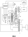
- FIG. 1 is a schematic configuration diagram of a vehicle on which a belt continuously variable transmission according to the embodiment of the present invention is mounted.
- This vehicle includes an engine 1 as a driving force source. Output rotation of the engine 1 is transmitted to a driving wheel 7 via a torque converter 2, a first gear train 3, a transmission 4, a second gear train 5, and a differential gear 6.
- a parking mechanism 8 that mechanically unrotatably locks an output shaft of the transmission 4 in parking is disposed on the second gear train 5.
- the engine 1 is an internal combustion engine such as a gasoline engine and a diesel engine.
- An engine controller 13 controls a rotation speed and a torque of the engine.
- the torque converter 2 includes a lock-up clutch 2a. If the lock-up clutch 2a is engaged, slip at the torque converter 2 disappears, ensuring improving transmission efficiency of the torque converter 2.
- the vehicle includes an oil pump 10 that is driven by using a part of power of the engine 1, a hydraulic control circuit 11 that regulates hydraulic pressure from the oil pump 10 to supply the hydraulic pressure to each part of the transmission 4, and a transmission controller 12 that controls the hydraulic control circuit 11.
- the transmission 4 is a continuously variable transmission including a variator 20 and a sub-transmission mechanism 30 disposed in series with respect to the variator 20.
- “[D]isposed in series” means that the variator 20 and the sub-transmission mechanism 30 are disposed in series in a power transmission path from the engine 1 up to the driving wheel 7.
- the sub-transmission mechanism 30 may be disposed at an input side of the variator 20.
- the variator 20 is a continuously variable transmission mechanism including a primary pulley 21, a secondary pulley 22, and a belt 23 stretched around the pulleys 21 and 22.
- the pulleys 21 and 22 include fixed conical plates 21f and 22f, movable conical plates 21m and 22m disposed in a state where sheave surfaces are opposed to the fixed conical plates 21f and 22f to form grooves with the fixed conical plates 21f and 22f, and hydraulic cylinders 21p and 22p disposed at back surfaces of the movable conical plates 21m and 22m to axially displace the movable conical plates 21m and 22m, respectively.
- Adjusting hydraulic pressure (a primary pressure Ppri and a secondary pressure Psec) supplied to the pulleys 21 and 22 changes force that the pulleys 21 and 22 sandwich the belt 23 to change a torque capacity (a transmissive maximum torque) of the variator 20, and changes a groove width to change contact radiuses of the belt 23 and the respective pulleys 21 and 22, thus a speed ratio of the variator 20 steplessly changes.
- the sub-transmission mechanism 30 is a transmission mechanism having two stages for forward and one stage for backward.
- the sub-transmission mechanism 30 includes a Ravigneaux type planetary gear mechanism 31 where carriers of two planetary gears are coupled, and a plurality of friction elements 32 to 34 (a Low brake 32, a High clutch 33, and a Rev brake 34). Adjusting hydraulic pressure supplied to the friction elements 32 to 34 to change engagement states of the friction elements 32 to 34 changes a gear position of the sub-transmission mechanism 30.
- the transmission controller 12 includes a CPU, a storage device including a RAM and a ROM, input/output interfaces, and a bus that mutually couples them.
- the input signals include the following signals:
- the storage device of the transmission controller 12 stores a shift control program of the transmission 4 and a shift map used in this shift control program.
- the transmission controller 12 reads the shift control program stored in the storage device to cause the CPU to execute this shift control program, thus performing a predetermined arithmetic process to a signal input via the input interface.
- the transmission controller 12 sets an instruction pressure of the hydraulic pressure supplied to each part of the transmission 4 and outputs the set instruction pressure to the hydraulic control circuit 11 via the input/output interfaces.
- the transmission controller 12 outputs an engine control signal (for example, a torque down request) to the engine controller 13 as necessary.
- the hydraulic control circuit 11 includes a plurality of flow paths and a plurality of hydraulic control valves.
- the hydraulic control circuit 11 controls the plurality of hydraulic control valves on the basis of the instruction pressure from the transmission controller 12 to switch a supply passage of the hydraulic pressure and generates the hydraulic pressure according to the instruction pressure to supply the hydraulic pressure to each part of the transmission 4. This performs a shift of the variator 20, the change of the gear position of the sub-transmission mechanism 30, capacity control of the respective friction elements 32 to 34, and an engagement or a disengagement of the lock-up clutch 2a.
- the transmission controller 12 controls the transmission 4 on the basis of the oil temperature obtained from the oil temperature sensor 50. Since, with the hydraulic oil of the transmission 4 at a low temperature, the viscosity increases while the fluidity decreases, responsiveness to a control target is deteriorated with the low oil temperature of the hydraulic oil. Therefore, the transmission controller 12 performs a control according to the oil temperature of the hydraulic oil detected by the oil temperature sensor 50.
- the transmission controller 12 controls the behavior of the transmission 4, such as reduction of the shift speed and restriction of a shift range of the variator 20.
- the transmission controller 12 executes an instruction (a torque down request) to restrict an output torque to the engine 1 as the driving force source in addition to the control of the transmission 4 at the low oil temperature.
- the transmission controller 12 requests a torque-down to the engine 1.
- the transmission controller 12 performs the following control.
- the transmission controller 12 estimates the oil temperature by another method.
- the oil temperature of the hydraulic oil is also estimated to be low.
- the predetermined period is defined until completion of warming-up of the engine 1 (for example, several to several ten minutes).
- the engine water temperature is obtained from the engine controller 13. As described above, considering a margin for the deterioration of efficiency of the transmission 4 at the low oil temperature, the oil temperature is estimated as the lowest value among the assumed temperatures.
- the oil temperature of the hydraulic oil is estimated to be sufficiently high.
- the transmission controller 12 performs the control according to the oil temperature detected by the oil temperature sensor 50, if the oil temperature sensor 50 cannot detect the oil temperature, the transmission controller 12 performs the control according to the estimated value of oil temperature.
- the case where after the signal from the oil temperature sensor 50 cannot be temporarily transmitted due to such as a poor contact, the conduction is restored and the signal from the oil temperature sensor 50 can be transmitted again is assumed.
- the transmission controller 12 changes the control to the control according to the obtained oil temperature.
- FIG. 2 is a timing chart for the control of the transmission 4 performed by the transmission controller 12 according to this embodiment according to the oil temperature.
- FIG. 2 illustrates, from the upper stage, the oil temperature, an oil temperature sensor abnormal flag, a torque, and a vehicle speed as respective timing charts with a time as the horizontal axis.
- the value of the oil temperature transmitted from the oil temperature sensor 50 is indicated by the dotted line and the oil temperature (any of the oil temperature from the oil temperature sensor 50 and the estimated value of the oil temperature) used by the transmission controller 12 for control is indicated by the solid line.
- the oil temperature sensor abnormal flag is set when the transmission controller 12 determines that the oil temperature sensor 50 is abnormal and is reset when the oil temperature sensor 50 is not determined as abnormal.
- a request torque on the basis of an operation of an accelerator pedal by a driver is indicated by the dotted line
- the command value of the torque down request of the transmission controller 12 is indicated by the one dot chain line
- the output torque actually output from the engine 1 is indicated by the solid line.
- the transmission controller 12 determines the speed ratio of the transmission 4 according to, for example, the input rotation speed, the vehicle speed, and the torque request to perform the shift control. At this time, the control according to the oil temperature obtained from the oil temperature sensor 50 is performed.
- the transmission controller 12 detects the oil temperature as the lowest state on the basis of the input signal. The transmission controller 12 instructs the torque down request to the engine 1 according to the detected low oil temperature.
- the driver depresses the accelerator pedal to request the request torque (the dotted line) to the engine 1.
- the transmission controller 12 instructs the torque down request (the one dot chain line)
- the engine controller 13 compares the request torque indicated by the dotted line with the command value of the torque down request indicated by the one dot chain line and selects any ones of the smaller one as the output torque. Consequently, the engine 1 outputs the output torque indicated by the solid line.
- the transmission controller 12 determines that the oil temperature sensor 50 is abnormal and cannot correctly detect the oil temperature.
- the predetermined period is defined, for example, several seconds.
- the transmission controller 12 determines that the oil temperature sensor 50 is abnormal at a timing t02 and sets the oil temperature sensor abnormal flag. With the oil temperature sensor abnormal flag set, the transmission controller 12 estimates the oil temperature on the basis of the engine water temperature or a similar value, instead of the signal output from the oil temperature sensor 50, and uses the estimated oil temperature for control.
- the transmission controller 12 continuously instructs the torque down request to the engine 1.
- the engine 1 outputs the output torque indicated by the solid line on the basis of the command value of the torque down request.
- the request torque temporarily falls below the command value of the torque down request between a timing t03 and a timing t04.
- the request torque smaller than the command value of the torque down request is output (indicated by the solid line).
- the transmission controller 12 determines that the oil temperature sensor 50 is normal if the signal level output from the oil temperature sensor 50 changes for equal to or more than the predetermined period.
- the predetermined period is defined, for example, several seconds as described above.
- the transmission controller 12 When the predetermined period passes at a timing t06 and the oil temperature sensor 50 is determined as normal, the transmission controller 12 resets the oil temperature sensor abnormal flag. In this case, the transmission controller 12 performs the control according to the oil temperature output from the oil temperature sensor 50.
- the transmission controller 12 switches the control from the control according to the estimated oil temperature to the control according to the detected oil temperature by the oil temperature sensor 50. At this time, the following problem occurs when the estimated value of the oil temperature differs from the detected oil temperature.
- the transmission controller 12 instructs the torque down request to the engine 1.
- the transmission controller 12 obtains the oil temperature from the oil temperature sensor 50 again, the obtained oil temperature differs from the estimated value, and the oil temperature becomes out of the range in which the torque down request is performed, the torque down request to the engine 1 is canceled.
- This embodiment performs the following control to reduce such sudden acceleration.
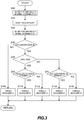
- FIG. 3 is a flowchart for the control executed by the transmission controller 12 according to this embodiment.
- the transmission controller 12 executes the flowchart illustrated in FIG. 3 at predetermined cycles (for example, 10 ms).
- the transmission controller 12 determines that the oil temperature sensor 50 is abnormal and sets the oil temperature sensor abnormal flag.
- the transmission controller 12 instructs the torque down request of the engine 1 to the engine controller 13 at Step S20.
- Step S30 when the transmission controller 12 determines that the oil temperature sensor 50 transmits the normal signal by the signal output from the oil temperature sensor 50, the transmission controller 12 determines that the oil temperature sensor 50 is normal and resets the oil temperature sensor abnormal flag.
- the transmission controller 12 determines whether the accelerator pedal has been depressed by the driver at the timing of Step S30 or not (whether the accelerator state is ON or not).
- Step S100 When it is determined that the accelerator state is not ON, the step transitions to Step S100 and the transmission controller 12 executes a torque recovery process A.
- the torque recovery process will be described later.
- Step S50 the transmission controller 12 determines whether a gradient of a current road surface is an uphill road or not. Whether the road surface is the uphill road or not may be determined by providing a gradient sensor in the vehicle or may be obtained through a calculation from the output torque from the engine 1, the vehicle speed, and the speed ratio. Whether the road surface is the uphill road or not is determined by, for example, the gradient of the road surface is equal to or more than several percent or not.
- Step S60 the transmission controller 12 determines whether the current accelerator pedal opening APO is larger than a predetermined opening X or not.
- the predetermined opening X is defined as the accelerator pedal opening APO intending to further accelerate the vehicle overcoming a resistance of the gradient on the uphill road.
- Step S110 When the accelerator pedal opening APO is larger than the predetermined opening X, the step transitions to Step S110, and the transmission controller 12 executes a torque recovery process B.
- Step S120 When the accelerator pedal opening APO is equal to or less than the predetermined opening X, the step transitions to Step S120, and the transmission controller 12 executes a torque recovery process C.
- Step S50 When the road surface is determined as not the uphill road at Step S50, the step transitions to Step S70, and the transmission controller 12 determines whether the current accelerator pedal opening APO is larger than a predetermined opening Y or not.
- Step S130 When the accelerator pedal opening APO is larger than the predetermined opening Y, the step transitions to Step S130, and the transmission controller 12 executes a torque recovery process D.
- the step transitions to Step S120, and the transmission controller 12 executes a torque recovery process E.
- the predetermined opening Y is an opening smaller than the predetermined opening X. Even when the driver requests the identical acceleration, the acceleration on the uphill road requires the larger accelerator pedal opening APO. Therefore, the predetermined opening X is set as a value including the resistance on the uphill road relative to the predetermined opening Y.
- the torque recovery process A is a process when the accelerator is not ON when the oil temperature sensor 50 becomes normal, that is, the process when the driver does not request the torque.
- the torque recovery process A recovers the command value of the torque down request to a level at which the torque down request is not performed at the gentlest gradient (a time change rate of torque [Nm/sec]) compared with the other torque recovery processes described later.
- the torque recovery process B is a process in the state of the accelerator being ON when the oil temperature sensor 50 becomes normal, the road surface is the uphill road, and the accelerator pedal opening APO is larger than the predetermined opening X.
- the torque recovery process B recovers the command value of the torque down request by the steepest gradient compared with the other processes.
- the torque recovery process C is a process in the state of the accelerator being ON when the oil temperature sensor 50 becomes normal and the accelerator pedal opening APO is equal to or less than the predetermined opening X while the road surface is the uphill road.
- the torque recovery process C recovers the command value of the torque down request at a comparatively steep gradient
- the torque recovery process C recovers the command value at a gradient gentler than the torque recovery process B to reduce the sudden acceleration during the torque recovery.
- the cancel of the torque down request may be configured to be quicker as the degree of the uphill road becomes large according to the degree of the uphill road (according to the magnitude of the gradient of the road surface).
- the torque recovery process D is a process in the state of the accelerator being ON when the oil temperature sensor 50 becomes normal, the road surface is not the uphill road, and the accelerator pedal opening APO is larger than the predetermined opening Y.
- the torque recovery process D recovers the command value of the torque down request at a comparatively steep gradient. While the gradient at this time is steeper than the torque recovery process C, the torque recovery process D recovers the command value at the gradient gentler than the torque recovery process B to reduce the sudden acceleration during the torque recovery.
- the torque recovery process E is a process in the state of the accelerator being ON when the oil temperature sensor 50 becomes normal, the road surface is not the uphill road, and the accelerator pedal opening APO is equal to or less than the predetermined opening Y.
- the torque recovery process E recovers the command value of the torque down request at a gradient gentler than the torque recovery process D to reduce the sudden acceleration during the torque recovery after the oil temperature sensor 50 recovers normally.
- the torque recovery processes which recover the torque down request when the oil temperature sensor 50 determined as a fault becomes normal, controls the gradient (the time change rate of the torque) of recovering the control value of the torque down request on the basis of the accelerator pedal opening APO and the gradient of the road surface.
- Such control ensures restricting the acceleration of the vehicle caused by the sudden cancel of the torque down request and also ensures maintaining the vehicle with the small restriction of acceleration when the torque is required. Especially, this ensures preventing the vehicle from stopping and retreating due to the torque down request on the uphill road and also ensures improving restartability.
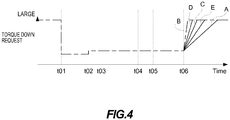
- FIG. 4 is an explanatory drawing illustrating the torque recovery process executed by the transmission controller 12 according to this embodiment.
- FIG. 4 is a timing chart illustrating the time change of the command value of the torque down request according to this embodiment and corresponding to FIG. 2 .
- the transmission controller 12 cancels the torque down request.
- the torque down request is suddenly canceled, the output torque of the engine 1 suddenly rises up and the vehicle is suddenly accelerated in some cases.
- the gradient of the command value when the torque down request is canceled is controlled on the basis of the accelerator pedal opening APO by the driver and the gradient of the road surface.
- the torque recovery process B recovers the command value of the torque down request at the steepest gradient, the gradient becomes gentle in the order of the torque recovery process D, the torque recovery process C, and the torque recovery process E, and the torque recovery process A recovers the command value of the torque down request at the gentlest gradient.
- the transmission controller 12 changes the command value of the torque down request so as to be gradually canceled at the predetermined gradient (the time change rate of the torque) in the torque recovery processes, this should not be constructed in a limiting sense.
- the command value of the torque down request may be changed in a stepped manner of several stages, or the command value of the torque down request may be changed so as to form a curved line.
- the time change rate in the process of change the command value of the torque down request may be determined on the basis of the accelerator pedal opening APO and the uphill road.
- the rotation of the engine 1 as the driving force source is input to the transmission 4.
- the speed ratio is controlled on the basis of the hydraulic pressure of the hydraulic oil.
- the transmission 4 includes the oil temperature sensor 50 as an oil temperature detecting unit configured to detect the oil temperature of the hydraulic oil and the transmission controller 12 configured to perform the control of the speed ratio on the basis of the oil temperature obtained from the oil temperature sensor 50.
- the transmission controller 12 is configured such that if the transmission controller 12 fails to obtain the oil temperature from the oil temperature sensor 50, the transmission controller 12 outputs the command (the torque down request) to restrict the output from the engine 1.
- the transmission controller 12 is configured such that if the transmission controller 12 has obtained the oil temperature from the oil temperature sensor 50 again, the transmission controller 12 gradually cancels the command (the torque down request) to restrict the output from the engine 1.
- the embodiment of the present invention restricts the output from the engine 1 by the torque down request when the oil temperature sensor 50 has failed to obtain the oil temperature, and when the oil temperature sensor 50 has obtained the oil temperature again afterwards, the embodiment gradually cancels the torque down request. Therefore, this embodiment ensures restricting the acceleration of the vehicle caused by the sudden cancel of the restriction on the output from the engine 1 when the oil temperature has been obtained again from the oil temperature sensor 50.
- the embodiment of the present invention is configured such that when the transmission controller 12 has obtained the oil temperature again from the oil temperature sensor 50, the cancel of the torque down request is quickened as the request torque to the engine 1 becomes large.
- the embodiment of the present invention is configured to quicken the cancel of the torque down request as the accelerator pedal opening APO becomes large.
- the embodiment of the present invention is configured such that the cancel of the torque down request is quickened as the gradient of the uphill road becomes steep when the transmission controller 12 has obtained the oil temperature again from the oil temperature sensor 50.
- Such configuration reduces the stop and the retreat of the vehicle by the torque down request on the uphill road by quickening the cancel of the torque down request and allows the vehicle to promptly restart and accelerate after the torque down request is canceled.
- the embodiment of the present invention is configured such that when the signal indicative of the change in oil temperature from the oil temperature sensor 50 continues for equal to or more than the predetermined period, the transmission controller 12 determines that the oil temperature has been obtained again.
- Such configuration allows the determination of the normal recovery of the oil temperature sensor 50 by the signal indicative of the normal oil temperature from the oil temperature sensor 50 continuing for equal to or more than the predetermined period and allows the cancel of the torque down request at the timing at which the oil temperature sensor 50 recovers normally. This effect corresponds to claim 5.
- the variator 20 may be a continuously variable transmission mechanism where the chain is wound around over the pulleys 21, 22 instead of the V belt 23.
- the variator 20 may be a toroidal type continuously variable transmission mechanism where a tiltable power roller is disposed between an input disk and an output disk.
- the embodiment describes the example that the engine 1 as the internal combustion engine is provided as the driving force source, the configuration is not limited to this.
- the embodiment is similarly applicable to an electric vehicle using an electric motor as the driving force source and a hybrid vehicle using both an engine and an electric motor as the driving force sources.
Landscapes
- Engineering & Computer Science (AREA)
- Mechanical Engineering (AREA)
- General Engineering & Computer Science (AREA)
- Combustion & Propulsion (AREA)
- Chemical & Material Sciences (AREA)
- Transportation (AREA)
- Automation & Control Theory (AREA)
- Oil, Petroleum & Natural Gas (AREA)
- Human Computer Interaction (AREA)
- Physics & Mathematics (AREA)
- Mathematical Physics (AREA)
- Control Of Transmission Device (AREA)
- Control Of Vehicle Engines Or Engines For Specific Uses (AREA)
Abstract
Description
- The present invention relates to an automatic transmission in which shift is controlled by hydraulic pressure.
- With an automatic transmission in which shift is controlled by hydraulic pressure of hydraulic oil, since the hydraulic oil changes the viscosity and the fluidity depending on a temperature, an oil temperature sensor to detect the oil temperature of the hydraulic oil is provided, and the shift is controlled according to the oil temperature.
- Here, since an abnormal oil temperature sensor cannot correctly detect the oil temperature and therefore a speed ratio cannot be accurately controlled, there has been known a shift control device (see
JP2010-203529A - The technique described in
JP2010-203529A - In such control, for example, when the oil temperature sensor recovers from a temporal abnormality, such as a temporal poor contact of a connector, to a normal state again, since the reduced control during abnormality returns to the normal control, a behavior of a vehicle changes, possibly giving uncomfortable feeling to a driver. Especially, while the driver requests acceleration, a sudden acceleration possibly occurs when the control returns to normal.
- The present invention has been made in consideration of such problem and the object is to ensure reducing a change in behavior of a vehicle even when an oil temperature sensor temporarily becomes abnormal.
- According to one aspect of this invention, an automatic transmission to which a rotation of a driving force source is input, the automatic transmission where a speed ratio is controlled on a basis of hydraulic pressure of hydraulic oil, the automatic transmission includes an oil temperature detecting unit configured to detect an oil temperature of the hydraulic oil, and a controller configured to perform the control of the speed ratio on a basis of the oil temperature obtained from the oil temperature detecting unit, wherein the controller is configured such that if the controller has failed to obtain the oil temperature from the oil temperature detecting unit, the controller outputs a command to restrict an output from the driving force source, and such that if the controller has obtained the oil temperature from the oil temperature detecting unit again, the controller gradually cancels the command to restrict the output from the driving force source.
- According to another aspect of this invention, a control method of automatic transmission to which a rotation of a driving force source is input, the automatic transmission where a speed ratio is controlled on a basis of hydraulic pressure of hydraulic oil, the control method includes obtaining an oil temperature of the hydraulic oil, performing the control of the speed ratio on a basis of the obtained oil temperature, outputting a command to restrict an output from the driving force source if the obtaining the oil temperature has failed, and gradually canceling the command to restrict the output from the driving force source if the oil temperature has been obtained again.
- According to these aspects, if the oil temperature cannot be obtained from the oil temperature detecting unit, the output from the driving force source is restricted. Afterwards, if the oil temperature has been obtained from the oil temperature detecting unit again, the command to restrict the output from the driving force source is gradually canceled. Accordingly, sudden acceleration of the vehicle due to the sudden cancel of the restriction on the output from the driving force source can be prevented.
-
-
FIG. 1 is an explanatory drawing illustrating a configuration of a vehicle that includes an automatic transmission according to an embodiment of the present invention. -
FIG. 2 is a timing chart for control of a transmission executed according to an oil temperature according to the embodiment of the present invention. -
FIG. 3 is a flowchart for a control by a transmission controller according to the embodiment of the present invention. -
FIG. 4 is a timing chart illustrating a time change of a command value of a torque down request according to the embodiment of the present invention. - The following describes an embodiment of the present invention with reference to the accompanying drawings.
-
FIG. 1 is a schematic configuration diagram of a vehicle on which a belt continuously variable transmission according to the embodiment of the present invention is mounted. This vehicle includes anengine 1 as a driving force source. Output rotation of theengine 1 is transmitted to adriving wheel 7 via atorque converter 2, afirst gear train 3, atransmission 4, asecond gear train 5, and adifferential gear 6. Aparking mechanism 8 that mechanically unrotatably locks an output shaft of thetransmission 4 in parking is disposed on thesecond gear train 5. - The
engine 1 is an internal combustion engine such as a gasoline engine and a diesel engine. Anengine controller 13 controls a rotation speed and a torque of the engine. - The
torque converter 2 includes a lock-up clutch 2a. If the lock-up clutch 2a is engaged, slip at thetorque converter 2 disappears, ensuring improving transmission efficiency of thetorque converter 2. - The vehicle includes an
oil pump 10 that is driven by using a part of power of theengine 1, a hydraulic control circuit 11 that regulates hydraulic pressure from theoil pump 10 to supply the hydraulic pressure to each part of thetransmission 4, and atransmission controller 12 that controls the hydraulic control circuit 11. - The
transmission 4 is a continuously variable transmission including avariator 20 and asub-transmission mechanism 30 disposed in series with respect to thevariator 20. "[D]isposed in series" means that thevariator 20 and thesub-transmission mechanism 30 are disposed in series in a power transmission path from theengine 1 up to thedriving wheel 7. In this example, while thesub-transmission mechanism 30 is disposed at an output side of thevariator 20, thesub-transmission mechanism 30 may be disposed at an input side of thevariator 20. - The
variator 20 is a continuously variable transmission mechanism including aprimary pulley 21, asecondary pulley 22, and abelt 23 stretched around thepulleys pulleys conical plates 21f and 22f, movableconical plates conical plates 21f and 22f to form grooves with the fixedconical plates 21f and 22f, and hydraulic cylinders 21p and 22p disposed at back surfaces of the movableconical plates conical plates - Adjusting hydraulic pressure (a primary pressure Ppri and a secondary pressure Psec) supplied to the
pulleys pulleys belt 23 to change a torque capacity (a transmissive maximum torque) of thevariator 20, and changes a groove width to change contact radiuses of thebelt 23 and therespective pulleys variator 20 steplessly changes. - The
sub-transmission mechanism 30 is a transmission mechanism having two stages for forward and one stage for backward. Thesub-transmission mechanism 30 includes a Ravigneaux typeplanetary gear mechanism 31 where carriers of two planetary gears are coupled, and a plurality offriction elements 32 to 34 (aLow brake 32, a High clutch 33, and a Rev brake 34). Adjusting hydraulic pressure supplied to thefriction elements 32 to 34 to change engagement states of thefriction elements 32 to 34 changes a gear position of thesub-transmission mechanism 30. - The
transmission controller 12 includes a CPU, a storage device including a RAM and a ROM, input/output interfaces, and a bus that mutually couples them. - Various signals are input to the
transmission controller 12 via the input/output interfaces. The input signals include the following signals: - A signal from an accelerator
pedal opening sensor 41 that detects an accelerator pedal opening APO indicative of a manipulated variable of an accelerator pedal - A signal from a primary
rotational speed sensor 42 that detects a primary rotation speed Npri as a rotation speed of theprimary pulley 21 - A signal from an output
rotational speed sensor 43 that detects an output rotation speed (∞ vehicle speed) of thetransmission 4 - A signal from a
line pressure sensor 44 that detects a line pressure PL - A signal from a
primary pressure sensor 45 that detects the primary pressure Ppri - A signal from a
secondary pressure sensor 46 that detects the secondary pressure Psec - A signal from an
inhibitor switch 47 that detects a position of a select lever - A signal from a secondary rotational speed sensor 48 that detects a secondary rotation speed Nsec as a rotation speed of the
secondary pulley 22 - A signal from an
oil temperature sensor 50 that detects the oil temperature of thetransmission 4 - A signal indicative of operating states (the rotation speed and the torque) of
engine 1 from theengine controller 13 - The storage device of the
transmission controller 12 stores a shift control program of thetransmission 4 and a shift map used in this shift control program. Thetransmission controller 12 reads the shift control program stored in the storage device to cause the CPU to execute this shift control program, thus performing a predetermined arithmetic process to a signal input via the input interface. Thetransmission controller 12 sets an instruction pressure of the hydraulic pressure supplied to each part of thetransmission 4 and outputs the set instruction pressure to the hydraulic control circuit 11 via the input/output interfaces. Thetransmission controller 12 outputs an engine control signal (for example, a torque down request) to theengine controller 13 as necessary. - The hydraulic control circuit 11 includes a plurality of flow paths and a plurality of hydraulic control valves. The hydraulic control circuit 11 controls the plurality of hydraulic control valves on the basis of the instruction pressure from the
transmission controller 12 to switch a supply passage of the hydraulic pressure and generates the hydraulic pressure according to the instruction pressure to supply the hydraulic pressure to each part of thetransmission 4. This performs a shift of thevariator 20, the change of the gear position of thesub-transmission mechanism 30, capacity control of therespective friction elements 32 to 34, and an engagement or a disengagement of the lock-up clutch 2a. - The following describes the control of the
transmission controller 12 according to the oil temperature in the thus configuredtransmission 4. - The
transmission controller 12 controls thetransmission 4 on the basis of the oil temperature obtained from theoil temperature sensor 50. Since, with the hydraulic oil of thetransmission 4 at a low temperature, the viscosity increases while the fluidity decreases, responsiveness to a control target is deteriorated with the low oil temperature of the hydraulic oil. Therefore, thetransmission controller 12 performs a control according to the oil temperature of the hydraulic oil detected by theoil temperature sensor 50. - Especially, the viscosity of the hydraulic oil increases at the low oil temperature (for example, below zero); therefore, there is a possibility that the responsiveness of the friction engaging elements is deteriorated and torque transmission efficiency of the
transmission 4 is deteriorated. In such case, thetransmission controller 12 controls the behavior of thetransmission 4, such as reduction of the shift speed and restriction of a shift range of thevariator 20. Thetransmission controller 12 executes an instruction (a torque down request) to restrict an output torque to theengine 1 as the driving force source in addition to the control of thetransmission 4 at the low oil temperature. - When the oil temperature is higher than a cooling water temperature of the
engine 1 as well, in the case of a large load, such as a large torque being input to thetransmission 4, there is a possibility that the hydraulic oil and the friction engaging elements are deteriorated. In such case as well, thetransmission controller 12 requests a torque-down to theengine 1. - If the oil temperature cannot be obtained from the
oil temperature sensor 50 in the control according to the oil temperature, thetransmission controller 12 performs the following control. - If the
transmission controller 12 cannot obtain the oil temperature from theoil temperature sensor 50 due to, for example, a fault in theoil temperature sensor 50 and poor contact of a harness and a connector coupled to theoil temperature sensor 50, thetransmission controller 12 estimates the oil temperature by another method. - When the
engine 1 has just been started (within a predetermined period from the start of the engine 1) and the engine water temperature is low (for example, below zero), the oil temperature of the hydraulic oil is also estimated to be low. The predetermined period is defined until completion of warming-up of the engine 1 (for example, several to several ten minutes). The engine water temperature is obtained from theengine controller 13. As described above, considering a margin for the deterioration of efficiency of thetransmission 4 at the low oil temperature, the oil temperature is estimated as the lowest value among the assumed temperatures. - Meanwhile, when the warming-up of the
engine 1 is completed and the engine water temperature becomes the predetermined water temperature (for example, 90°C), the oil temperature of the hydraulic oil is estimated to be sufficiently high. - Thus, while the
transmission controller 12 performs the control according to the oil temperature detected by theoil temperature sensor 50, if theoil temperature sensor 50 cannot detect the oil temperature, thetransmission controller 12 performs the control according to the estimated value of oil temperature. - Here, the case where the
oil temperature sensor 50 cannot detect the oil temperature but can detect the oil temperature again while thetransmission controller 12 performs the control according to the estimated value of oil temperature is examined. - As one example, the case where after the signal from the
oil temperature sensor 50 cannot be temporarily transmitted due to such as a poor contact, the conduction is restored and the signal from theoil temperature sensor 50 can be transmitted again is assumed. - In such case, if the
transmission controller 12 has obtained the oil temperature from theoil temperature sensor 50 after the control according to the estimated value of oil temperature, thetransmission controller 12 changes the control to the control according to the obtained oil temperature. -
FIG. 2 is a timing chart for the control of thetransmission 4 performed by thetransmission controller 12 according to this embodiment according to the oil temperature. -
FIG. 2 illustrates, from the upper stage, the oil temperature, an oil temperature sensor abnormal flag, a torque, and a vehicle speed as respective timing charts with a time as the horizontal axis. - Regarding the oil temperature, the value of the oil temperature transmitted from the
oil temperature sensor 50 is indicated by the dotted line and the oil temperature (any of the oil temperature from theoil temperature sensor 50 and the estimated value of the oil temperature) used by thetransmission controller 12 for control is indicated by the solid line. - The oil temperature sensor abnormal flag is set when the
transmission controller 12 determines that theoil temperature sensor 50 is abnormal and is reset when theoil temperature sensor 50 is not determined as abnormal. - Regarding the torque, a request torque on the basis of an operation of an accelerator pedal by a driver is indicated by the dotted line, the command value of the torque down request of the
transmission controller 12 is indicated by the one dot chain line, and the output torque actually output from theengine 1 is indicated by the solid line. - The
transmission controller 12 determines the speed ratio of thetransmission 4 according to, for example, the input rotation speed, the vehicle speed, and the torque request to perform the shift control. At this time, the control according to the oil temperature obtained from theoil temperature sensor 50 is performed. - At a timing t01, when a signal level indicative of the oil temperature output from the
oil temperature sensor 50 becomes the minimum due to a cause such as a fault of theoil temperature sensor 50, thetransmission controller 12 detects the oil temperature as the lowest state on the basis of the input signal. Thetransmission controller 12 instructs the torque down request to theengine 1 according to the detected low oil temperature. - The driver depresses the accelerator pedal to request the request torque (the dotted line) to the
engine 1. Here, when thetransmission controller 12 instructs the torque down request (the one dot chain line), theengine controller 13 compares the request torque indicated by the dotted line with the command value of the torque down request indicated by the one dot chain line and selects any ones of the smaller one as the output torque. Consequently, theengine 1 outputs the output torque indicated by the solid line. - When the signal level output from the
oil temperature sensor 50 does not change for equal to or more than a predetermined period, thetransmission controller 12 determines that theoil temperature sensor 50 is abnormal and cannot correctly detect the oil temperature. The predetermined period is defined, for example, several seconds. - The
transmission controller 12 determines that theoil temperature sensor 50 is abnormal at a timing t02 and sets the oil temperature sensor abnormal flag. With the oil temperature sensor abnormal flag set, thetransmission controller 12 estimates the oil temperature on the basis of the engine water temperature or a similar value, instead of the signal output from theoil temperature sensor 50, and uses the estimated oil temperature for control. - In the example illustrated in
FIG. 2 , since the estimated value of the oil temperature (indicated by the solid line) becomes a low value at and after a timing t02, thetransmission controller 12 continuously instructs the torque down request to theengine 1. Theengine 1 outputs the output torque indicated by the solid line on the basis of the command value of the torque down request. - Furthermore, in the example illustrated in
FIG. 2 , by the driver returning the accelerator pedal, the request torque temporarily falls below the command value of the torque down request between a timing t03 and a timing t04. In this case, the request torque smaller than the command value of the torque down request is output (indicated by the solid line). - Afterwards, at a timing t05, assume that the
oil temperature sensor 50 recovers from the abnormality and theoil temperature sensor 50 outputs the correct signal. - In this case, the
transmission controller 12 determines that theoil temperature sensor 50 is normal if the signal level output from theoil temperature sensor 50 changes for equal to or more than the predetermined period. The predetermined period is defined, for example, several seconds as described above. - When the predetermined period passes at a timing t06 and the
oil temperature sensor 50 is determined as normal, thetransmission controller 12 resets the oil temperature sensor abnormal flag. In this case, thetransmission controller 12 performs the control according to the oil temperature output from theoil temperature sensor 50. - When the
oil temperature sensor 50 becomes normal from abnormal, thetransmission controller 12 switches the control from the control according to the estimated oil temperature to the control according to the detected oil temperature by theoil temperature sensor 50. At this time, the following problem occurs when the estimated value of the oil temperature differs from the detected oil temperature. - When the estimated value of the oil temperature is lower or higher, the
transmission controller 12 instructs the torque down request to theengine 1. In the case where thetransmission controller 12 obtains the oil temperature from theoil temperature sensor 50 again, the obtained oil temperature differs from the estimated value, and the oil temperature becomes out of the range in which the torque down request is performed, the torque down request to theengine 1 is canceled. - At this time, when the driver keeps depressing the accelerator pedal intending for acceleration, the cancel of the torque down request increases the driving force by the
engine 1, possibly causing sudden acceleration. The increase in vehicle speed from the timing t06 inFIG. 2 suggests this. - This embodiment performs the following control to reduce such sudden acceleration.
-
FIG. 3 is a flowchart for the control executed by thetransmission controller 12 according to this embodiment. - The
transmission controller 12 executes the flowchart illustrated inFIG. 3 at predetermined cycles (for example, 10 ms). - When the signal level output from the
oil temperature sensor 50 does not change for equal to or more than the predetermined period at Step S10, thetransmission controller 12 determines that theoil temperature sensor 50 is abnormal and sets the oil temperature sensor abnormal flag. - When the oil temperature sensor abnormal flag is set, the
transmission controller 12 instructs the torque down request of theengine 1 to theengine controller 13 at Step S20. - Afterwards, at Step S30, when the
transmission controller 12 determines that theoil temperature sensor 50 transmits the normal signal by the signal output from theoil temperature sensor 50, thetransmission controller 12 determines that theoil temperature sensor 50 is normal and resets the oil temperature sensor abnormal flag. - Next, the
transmission controller 12 determines whether the accelerator pedal has been depressed by the driver at the timing of Step S30 or not (whether the accelerator state is ON or not). - When it is determined that the accelerator state is not ON, the step transitions to Step S100 and the
transmission controller 12 executes a torque recovery process A. The torque recovery process will be described later. - When the accelerator state is determined as ON, the step transitions to Step S50, and the
transmission controller 12 determines whether a gradient of a current road surface is an uphill road or not. Whether the road surface is the uphill road or not may be determined by providing a gradient sensor in the vehicle or may be obtained through a calculation from the output torque from theengine 1, the vehicle speed, and the speed ratio. Whether the road surface is the uphill road or not is determined by, for example, the gradient of the road surface is equal to or more than several percent or not. - When the road surface is determined as the uphill road, the step transitions to Step S60, and the
transmission controller 12 determines whether the current accelerator pedal opening APO is larger than a predetermined opening X or not. The predetermined opening X is defined as the accelerator pedal opening APO intending to further accelerate the vehicle overcoming a resistance of the gradient on the uphill road. - When the accelerator pedal opening APO is larger than the predetermined opening X, the step transitions to Step S110, and the
transmission controller 12 executes a torque recovery process B. When the accelerator pedal opening APO is equal to or less than the predetermined opening X, the step transitions to Step S120, and thetransmission controller 12 executes a torque recovery process C. - When the road surface is determined as not the uphill road at Step S50, the step transitions to Step S70, and the
transmission controller 12 determines whether the current accelerator pedal opening APO is larger than a predetermined opening Y or not. - When the accelerator pedal opening APO is larger than the predetermined opening Y, the step transitions to Step S130, and the
transmission controller 12 executes a torque recovery process D. When the accelerator pedal opening APO is equal to or less than the predetermined opening Y, the step transitions to Step S120, and thetransmission controller 12 executes a torque recovery process E. - It should be noted that, the predetermined opening Y is an opening smaller than the predetermined opening X. Even when the driver requests the identical acceleration, the acceleration on the uphill road requires the larger accelerator pedal opening APO. Therefore, the predetermined opening X is set as a value including the resistance on the uphill road relative to the predetermined opening Y.
- After any of processes of these torque recovery processes A to E, this flowchart is terminated and the process returns to another process.
- The following describes the torque recovery processes A to E.
- The torque recovery process A is a process when the accelerator is not ON when the
oil temperature sensor 50 becomes normal, that is, the process when the driver does not request the torque. - In this case, it is unnecessary to immediately cancel the torque down request. Therefore, to cancel the torque down request, the torque recovery process A recovers the command value of the torque down request to a level at which the torque down request is not performed at the gentlest gradient (a time change rate of torque [Nm/sec]) compared with the other torque recovery processes described later.
- The torque recovery process B is a process in the state of the accelerator being ON when the
oil temperature sensor 50 becomes normal, the road surface is the uphill road, and the accelerator pedal opening APO is larger than the predetermined opening X. - In this case, since the torque request from the driver is large and the torque to maintain the vehicle speed is required due to the resistance on the uphill road, it is necessary to promptly cancel the torque down request and output the request torque from the
engine 1 after theoil temperature sensor 50 recovers normally. Therefore, the torque recovery process B recovers the command value of the torque down request by the steepest gradient compared with the other processes. - The torque recovery process C is a process in the state of the accelerator being ON when the
oil temperature sensor 50 becomes normal and the accelerator pedal opening APO is equal to or less than the predetermined opening X while the road surface is the uphill road. - In this case, although the torque request from the driver is not large, since the resistance on the uphill road requires the torque to maintain the vehicle speed, the torque down request needs to be promptly canceled after the
oil temperature sensor 50 recovers normally. Therefore, while the torque recovery process C recovers the command value of the torque down request at a comparatively steep gradient, the torque recovery process C recovers the command value at a gradient gentler than the torque recovery process B to reduce the sudden acceleration during the torque recovery. It should be noted that, not only the determination on whether the road surface is the uphill road or not, the cancel of the torque down request may be configured to be quicker as the degree of the uphill road becomes large according to the degree of the uphill road (according to the magnitude of the gradient of the road surface). - The torque recovery process D is a process in the state of the accelerator being ON when the
oil temperature sensor 50 becomes normal, the road surface is not the uphill road, and the accelerator pedal opening APO is larger than the predetermined opening Y. - In this case, although the road surface is a flat road, since the request torque from the driver is large, the torque down request needs to be promptly canceled after the
oil temperature sensor 50 recovers normally. Therefore, the torque recovery process D recovers the command value of the torque down request at a comparatively steep gradient. While the gradient at this time is steeper than the torque recovery process C, the torque recovery process D recovers the command value at the gradient gentler than the torque recovery process B to reduce the sudden acceleration during the torque recovery. - The torque recovery process E is a process in the state of the accelerator being ON when the
oil temperature sensor 50 becomes normal, the road surface is not the uphill road, and the accelerator pedal opening APO is equal to or less than the predetermined opening Y. - In this case, since the road surface is the flat road and the request torque from the driver is not large, the torque recovery process E recovers the command value of the torque down request at a gradient gentler than the torque recovery process D to reduce the sudden acceleration during the torque recovery after the
oil temperature sensor 50 recovers normally. - Thus, in this embodiment, the torque recovery processes, which recover the torque down request when the
oil temperature sensor 50 determined as a fault becomes normal, controls the gradient (the time change rate of the torque) of recovering the control value of the torque down request on the basis of the accelerator pedal opening APO and the gradient of the road surface. - Such control ensures restricting the acceleration of the vehicle caused by the sudden cancel of the torque down request and also ensures maintaining the vehicle with the small restriction of acceleration when the torque is required. Especially, this ensures preventing the vehicle from stopping and retreating due to the torque down request on the uphill road and also ensures improving restartability.
-
FIG. 4 is an explanatory drawing illustrating the torque recovery process executed by thetransmission controller 12 according to this embodiment. -
FIG. 4 is a timing chart illustrating the time change of the command value of the torque down request according to this embodiment and corresponding toFIG. 2 . - When the
oil temperature sensor 50 becomes the normal state from the abnormal state, thetransmission controller 12 cancels the torque down request. At this time, as described inFIG. 2 , when the torque down request is suddenly canceled, the output torque of theengine 1 suddenly rises up and the vehicle is suddenly accelerated in some cases. - Meanwhile, in the case of the road surface being the uphill road, when the output torque of the
engine 1 is restricted, the vehicle stops and the restarts after the stop becomes difficult, possibly causing a retreat of the vehicle. In such case, the output torque of theengine 1 needs to be increased immediately. - Therefore, as described in
FIG. 3 , the gradient of the command value when the torque down request is canceled is controlled on the basis of the accelerator pedal opening APO by the driver and the gradient of the road surface. - The torque recovery process B recovers the command value of the torque down request at the steepest gradient, the gradient becomes gentle in the order of the torque recovery process D, the torque recovery process C, and the torque recovery process E, and the torque recovery process A recovers the command value of the torque down request at the gentlest gradient.
- It should be noted that, while in this embodiment, the
transmission controller 12 changes the command value of the torque down request so as to be gradually canceled at the predetermined gradient (the time change rate of the torque) in the torque recovery processes, this should not be constructed in a limiting sense. The command value of the torque down request may be changed in a stepped manner of several stages, or the command value of the torque down request may be changed so as to form a curved line. The time change rate in the process of change the command value of the torque down request may be determined on the basis of the accelerator pedal opening APO and the uphill road. - As described above, with the embodiment of the present invention, the rotation of the
engine 1 as the driving force source is input to thetransmission 4. In thetransmission 4, the speed ratio is controlled on the basis of the hydraulic pressure of the hydraulic oil. Thetransmission 4 includes theoil temperature sensor 50 as an oil temperature detecting unit configured to detect the oil temperature of the hydraulic oil and thetransmission controller 12 configured to perform the control of the speed ratio on the basis of the oil temperature obtained from theoil temperature sensor 50. Thetransmission controller 12 is configured such that if thetransmission controller 12 fails to obtain the oil temperature from theoil temperature sensor 50, thetransmission controller 12 outputs the command (the torque down request) to restrict the output from theengine 1. Thetransmission controller 12 is configured such that if thetransmission controller 12 has obtained the oil temperature from theoil temperature sensor 50 again, thetransmission controller 12 gradually cancels the command (the torque down request) to restrict the output from theengine 1. - With such configuration, the embodiment of the present invention restricts the output from the
engine 1 by the torque down request when theoil temperature sensor 50 has failed to obtain the oil temperature, and when theoil temperature sensor 50 has obtained the oil temperature again afterwards, the embodiment gradually cancels the torque down request. Therefore, this embodiment ensures restricting the acceleration of the vehicle caused by the sudden cancel of the restriction on the output from theengine 1 when the oil temperature has been obtained again from theoil temperature sensor 50. - Additionally, the embodiment of the present invention is configured such that when the
transmission controller 12 has obtained the oil temperature again from theoil temperature sensor 50, the cancel of the torque down request is quickened as the request torque to theengine 1 becomes large. - With such configuration, in the case where the torque request of the
engine 1 is large such as the driver's request of the acceleration and the road surface being the uphill road, performing the cancel of torque down request quick ensures promptly restarting and accelerating the vehicle after the torque down request is canceled. - Additionally, when the
transmission controller 12 has obtained the oil temperature again from theoil temperature sensor 50, the embodiment of the present invention is configured to quicken the cancel of the torque down request as the accelerator pedal opening APO becomes large. - With such configuration, as the accelerator pedal opening APO by the driver becomes large and as the request of the acceleration becomes large, the cancel of the torque down request is quickened. This ensures promptly restarting and accelerating the vehicle after the cancel of the torque down request.
- The embodiment of the present invention is configured such that the cancel of the torque down request is quickened as the gradient of the uphill road becomes steep when the
transmission controller 12 has obtained the oil temperature again from theoil temperature sensor 50. - Such configuration reduces the stop and the retreat of the vehicle by the torque down request on the uphill road by quickening the cancel of the torque down request and allows the vehicle to promptly restart and accelerate after the torque down request is canceled.
- The embodiment of the present invention is configured such that when the signal indicative of the change in oil temperature from the
oil temperature sensor 50 continues for equal to or more than the predetermined period, thetransmission controller 12 determines that the oil temperature has been obtained again. - Such configuration allows the determination of the normal recovery of the
oil temperature sensor 50 by the signal indicative of the normal oil temperature from theoil temperature sensor 50 continuing for equal to or more than the predetermined period and allows the cancel of the torque down request at the timing at which theoil temperature sensor 50 recovers normally. This effect corresponds to claim 5. - The embodiment of the present invention described above is merely illustration of one application example of the present invention and not of the nature to limit the technical scope of the present invention to the specific constructions of the embodiment.
- While the embodiment includes the belt continuously variable transmission mechanism as the
variator 20, thevariator 20 may be a continuously variable transmission mechanism where the chain is wound around over thepulleys V belt 23. Alternatively, thevariator 20 may be a toroidal type continuously variable transmission mechanism where a tiltable power roller is disposed between an input disk and an output disk. - While the embodiment describes the example that the
engine 1 as the internal combustion engine is provided as the driving force source, the configuration is not limited to this. The embodiment is similarly applicable to an electric vehicle using an electric motor as the driving force source and a hybrid vehicle using both an engine and an electric motor as the driving force sources. - With respect to the above description, the contents of application No.
2015-179855
Claims (6)
- An automatic transmission to which a rotation of a driving force source is input, the automatic transmission where a speed ratio is controlled on a basis of hydraulic pressure of hydraulic oil, the automatic transmission comprising:an oil temperature detecting unit configured to detect an oil temperature of the hydraulic oil; anda controller configured to perform the control of the speed ratio on a basis of the oil temperature obtained from the oil temperature detecting unit, whereinthe controller is configured:such that if the controller has failed to obtain the oil temperature from the oil temperature detecting unit, the controller outputs a command to restrict an output from the driving force source; andsuch that if the controller has obtained the oil temperature from the oil temperature detecting unit again, the controller gradually cancels the command to restrict the output from the driving force source.
- The automatic transmission according to claim 1, wherein
the controller is configured such that if the controller has obtained the oil temperature from the oil temperature detecting unit again, the controller quickens the cancel of the command to restrict the output from the driving force source as a request torque to the driving force source becomes large. - The automatic transmission according to claim 2, wherein
the controller is configured such that if the controller has obtained the oil temperature from the oil temperature detecting unit again, the controller quickens the cancel of the command to restrict the output from the driving force source as an accelerator pedal opening becomes large. - The automatic transmission according to claim 2 or 3, wherein
the controller is configured such that if the controller has obtained the oil temperature from the oil temperature detecting unit again, the controller quickens the cancel of the command to restrict the output from the driving force source as a gradient of an uphill road becomes steep. - The automatic transmission according to any one of claims 1 to 4, wherein
the controller is configured such that if a signal indicative of a change in the oil temperature from the oil temperature detecting unit continues for equal to or more than a predetermined period, the controller determines that the oil temperature has been obtained again. - A control method of automatic transmission to which a rotation of a driving force source is input, the automatic transmission where a speed ratio is controlled on a basis of hydraulic pressure of hydraulic oil, the control method comprising:obtaining an oil temperature of the hydraulic oil;performing the control of the speed ratio on a basis of the obtained oil temperature;outputting a command to restrict an output from the driving force source if the obtaining the oil temperature has failed; andgradually canceling the command to restrict the output from the driving
force source if the oil temperature has been obtained again.
Applications Claiming Priority (2)
| Application Number | Priority Date | Filing Date | Title |
|---|---|---|---|
| JP2015179855 | 2015-09-11 | ||
| PCT/JP2016/074998 WO2017043339A1 (en) | 2015-09-11 | 2016-08-26 | Automatic transmission device and control method for automatic transmission device |
Publications (2)
| Publication Number | Publication Date |
|---|---|
| EP3348874A1 true EP3348874A1 (en) | 2018-07-18 |
| EP3348874A4 EP3348874A4 (en) | 2018-09-12 |
Family
ID=58239515
Family Applications (1)
| Application Number | Title | Priority Date | Filing Date |
|---|---|---|---|
| EP16844202.8A Withdrawn EP3348874A4 (en) | 2015-09-11 | 2016-08-26 | Automatic transmission device and control method for automatic transmission device |
Country Status (6)
| Country | Link |
|---|---|
| US (1) | US10549761B2 (en) |
| EP (1) | EP3348874A4 (en) |
| JP (1) | JP6559242B2 (en) |
| KR (1) | KR102033140B1 (en) |
| CN (1) | CN108027052B (en) |
| WO (1) | WO2017043339A1 (en) |
Families Citing this family (7)
| Publication number | Priority date | Publication date | Assignee | Title |
|---|---|---|---|---|
| US10690245B2 (en) * | 2017-11-09 | 2020-06-23 | GM Global Technology Operations LLC | Method and system for controlling a continuously variable transmission for a vehicle propulsion system |
| KR20200015158A (en) * | 2018-08-03 | 2020-02-12 | 현대자동차주식회사 | Belt pulley control method for continuously variable transmission |
| KR102551679B1 (en) * | 2018-11-23 | 2023-07-07 | 현대자동차주식회사 | Clutch control method for hybrid vehicle with dct |
| CN113631842B (en) * | 2019-03-15 | 2022-12-02 | 加特可株式会社 | Temperature sensor diagnostic device and diagnostic method for automatic transmission |
| CN111845699B (en) * | 2019-04-08 | 2022-08-19 | 长城汽车股份有限公司 | Vehicle control method and device |
| CN110985625B (en) * | 2019-12-30 | 2021-02-26 | 杭州肇鹏科技有限公司 | Stepless speed change device with built-in speed regulation component |
| CN114576353B (en) * | 2022-03-04 | 2024-05-17 | 潍柴动力股份有限公司 | Collaborative gear shifting method, system, vehicle and medium |
Family Cites Families (21)
| Publication number | Priority date | Publication date | Assignee | Title |
|---|---|---|---|---|
| JPH03244868A (en) * | 1990-02-20 | 1991-10-31 | Mitsubishi Electric Corp | Oil temperature sensor failure judgement for automatic transmission |
| JPH05209681A (en) * | 1992-01-31 | 1993-08-20 | Mazda Motor Corp | Oil pressure control device for automatic transmission |
| JPH07257236A (en) * | 1994-03-18 | 1995-10-09 | Toyota Motor Corp | Shift control device for automatic transmission |
| JPH07259984A (en) * | 1994-03-23 | 1995-10-13 | Toyota Motor Corp | Shift control device for automatic transmission |
| JPH1178617A (en) * | 1997-09-05 | 1999-03-23 | Nissan Motor Co Ltd | Integrated control system for engine and automatic transmission |
| JP3840079B2 (en) * | 2001-09-27 | 2006-11-01 | ジヤトコ株式会社 | Anti-slip device for toroidal type continuously variable transmission |
| JP3904065B2 (en) * | 2002-03-07 | 2007-04-11 | 株式会社デンソー | Shift control method and shift control device for automatic transmission |
| JP3910122B2 (en) * | 2002-08-30 | 2007-04-25 | ジヤトコ株式会社 | Engine output torque control device for vehicle transmission system |
| JP4378922B2 (en) | 2002-09-26 | 2009-12-09 | 株式会社ジェイテクト | Input signal monitoring device for four-wheel drive vehicle and drive force distribution control device for four-wheel drive vehicle |
| JP2004124841A (en) * | 2002-10-03 | 2004-04-22 | Jatco Ltd | Vehicle failure diagnosis device |
| JP2004316843A (en) * | 2003-04-18 | 2004-11-11 | Jatco Ltd | Control device for belt-type continuously variable transmission |
| DE102004002761B4 (en) * | 2004-01-20 | 2017-01-05 | Daimler Ag | Method for operating a drive train of a motor vehicle |
| JP4429263B2 (en) * | 2004-12-10 | 2010-03-10 | トヨタ自動車株式会社 | Power output device, automobile equipped with the same, control device for power output device, and control method for power output device |
| JP2009058023A (en) * | 2007-08-30 | 2009-03-19 | Aisin Aw Co Ltd | Oil temperature excessive rise prevention device for torque converter of vehicle automatic transmission with torque converter |
| JP2010101264A (en) * | 2008-10-24 | 2010-05-06 | Toyota Motor Corp | Automatic transmission control unit and method for limiting output |
| JP5195475B2 (en) * | 2009-02-04 | 2013-05-08 | トヨタ自動車株式会社 | Oil temperature sensor abnormality determination device and abnormality determination method |
| JP5187218B2 (en) * | 2009-02-12 | 2013-04-24 | 日産自動車株式会社 | Control device for four-wheel drive vehicle |
| JP5152040B2 (en) * | 2009-03-03 | 2013-02-27 | トヨタ自動車株式会社 | Shift control device |
| WO2012090428A1 (en) * | 2010-12-27 | 2012-07-05 | マツダ株式会社 | Control device for automatic transmission |
| JP5726710B2 (en) * | 2011-11-07 | 2015-06-03 | ジヤトコ株式会社 | Abnormality diagnosis method for oil temperature sensor for automatic transmission |
| JP5612015B2 (en) * | 2012-03-30 | 2014-10-22 | 本田技研工業株式会社 | Protection control device for automatic transmission |
-
2016
- 2016-08-26 US US15/758,243 patent/US10549761B2/en active Active
- 2016-08-26 EP EP16844202.8A patent/EP3348874A4/en not_active Withdrawn
- 2016-08-26 CN CN201680052019.8A patent/CN108027052B/en active Active
- 2016-08-26 KR KR1020187006292A patent/KR102033140B1/en not_active Expired - Fee Related
- 2016-08-26 JP JP2017539112A patent/JP6559242B2/en active Active
- 2016-08-26 WO PCT/JP2016/074998 patent/WO2017043339A1/en not_active Ceased
Also Published As
| Publication number | Publication date |
|---|---|
| EP3348874A4 (en) | 2018-09-12 |
| US20180244284A1 (en) | 2018-08-30 |
| KR20180037032A (en) | 2018-04-10 |
| JPWO2017043339A1 (en) | 2018-06-28 |
| CN108027052A (en) | 2018-05-11 |
| CN108027052B (en) | 2020-04-28 |
| WO2017043339A1 (en) | 2017-03-16 |
| JP6559242B2 (en) | 2019-08-14 |
| KR102033140B1 (en) | 2019-11-08 |
| US10549761B2 (en) | 2020-02-04 |
Similar Documents
| Publication | Publication Date | Title |
|---|---|---|
| US10549761B2 (en) | Automatic transmission and control method of the same | |
| JP5728422B2 (en) | Shift control device for belt type continuously variable transmission | |
| JP6513264B2 (en) | Control device for continuously variable transmission for vehicle | |
| CN102361787B (en) | Driving force control device | |
| KR101810341B1 (en) | Control device for stepped transmission mechanism | |
| US9026328B2 (en) | Automatic transmission and starting time control method | |
| US9434390B2 (en) | Vehicle control device and vehicle control method | |
| JP6584892B2 (en) | Vehicle sailing stop control method and control apparatus | |
| US10421449B2 (en) | Control device for vehicle and control method for vehicle | |
| JP5084870B2 (en) | Vehicle torque-down control device | |
| EP3348875A1 (en) | Continuously variable transmission and malfunction determination method therefor | |
| US10724627B2 (en) | Control device for vehicle and control method for vehicle | |
| US10086817B2 (en) | Control device and control method for vehicle | |
| US11524670B2 (en) | Control device for vehicle and control method for vehicle | |
| JP6725254B2 (en) | Vehicle control device | |
| JP2014137099A (en) | Transmission control device | |
| KR20180100683A (en) | Vehicle control device and vehicle control method | |
| US10690238B2 (en) | Device for controlling vehicular variator | |
| JP7743814B2 (en) | Vehicle control device | |
| JP6694286B2 (en) | Vehicle control device and vehicle control method | |
| EP3273106A1 (en) | Transmission control device and transmission control method | |
| JP2014062582A (en) | Control method for power train system, and power train system |
Legal Events
| Date | Code | Title | Description |
|---|---|---|---|
| PUAI | Public reference made under article 153(3) epc to a published international application that has entered the european phase |
Free format text: ORIGINAL CODE: 0009012 |
|
| 17P | Request for examination filed |
Effective date: 20180308 |
|
| AK | Designated contracting states |
Kind code of ref document: A1 Designated state(s): AL AT BE BG CH CY CZ DE DK EE ES FI FR GB GR HR HU IE IS IT LI LT LU LV MC MK MT NL NO PL PT RO RS SE SI SK SM TR |
|
| AX | Request for extension of the european patent |
Extension state: BA ME |
|
| A4 | Supplementary search report drawn up and despatched |
Effective date: 20180809 |
|
| RIC1 | Information provided on ipc code assigned before grant |
Ipc: B60W 10/107 20120101ALI20180804BHEP Ipc: F16H 59/72 20060101ALI20180804BHEP Ipc: F16H 61/662 20060101ALI20180804BHEP Ipc: B60W 10/04 20060101ALI20180804BHEP Ipc: B60W 10/101 20120101ALI20180804BHEP Ipc: F16H 61/12 20100101AFI20180804BHEP Ipc: F16H 63/50 20060101ALI20180804BHEP Ipc: B60W 10/105 20120101ALI20180804BHEP Ipc: B60W 10/06 20060101ALI20180804BHEP Ipc: F16H 61/66 20060101ALI20180804BHEP |
|
| STAA | Information on the status of an ep patent application or granted ep patent |
Free format text: STATUS: THE APPLICATION HAS BEEN WITHDRAWN |
|
| 18W | Application withdrawn |
Effective date: 20181109 |