EP3348843A1 - Blower device and cleaner - Google Patents
Blower device and cleaner Download PDFInfo
- Publication number
- EP3348843A1 EP3348843A1 EP16844181.4A EP16844181A EP3348843A1 EP 3348843 A1 EP3348843 A1 EP 3348843A1 EP 16844181 A EP16844181 A EP 16844181A EP 3348843 A1 EP3348843 A1 EP 3348843A1
- Authority
- EP
- European Patent Office
- Prior art keywords
- face
- ring
- impeller
- shaped cover
- radial direction
- Prior art date
- Legal status (The legal status is an assumption and is not a legal conclusion. Google has not performed a legal analysis and makes no representation as to the accuracy of the status listed.)
- Withdrawn
Links
Images


Classifications
-
- A—HUMAN NECESSITIES
- A47—FURNITURE; DOMESTIC ARTICLES OR APPLIANCES; COFFEE MILLS; SPICE MILLS; SUCTION CLEANERS IN GENERAL
- A47L—DOMESTIC WASHING OR CLEANING; SUCTION CLEANERS IN GENERAL
- A47L9/00—Details or accessories of suction cleaners, e.g. mechanical means for controlling the suction or for effecting pulsating action; Storing devices specially adapted to suction cleaners or parts thereof; Carrying-vehicles specially adapted for suction cleaners
-
- F—MECHANICAL ENGINEERING; LIGHTING; HEATING; WEAPONS; BLASTING
- F04—POSITIVE - DISPLACEMENT MACHINES FOR LIQUIDS; PUMPS FOR LIQUIDS OR ELASTIC FLUIDS
- F04D—NON-POSITIVE-DISPLACEMENT PUMPS
- F04D25/00—Pumping installations or systems
- F04D25/02—Units comprising pumps and their driving means
- F04D25/06—Units comprising pumps and their driving means the pump being electrically driven
- F04D25/0606—Units comprising pumps and their driving means the pump being electrically driven the electric motor being specially adapted for integration in the pump
-
- F—MECHANICAL ENGINEERING; LIGHTING; HEATING; WEAPONS; BLASTING
- F04—POSITIVE - DISPLACEMENT MACHINES FOR LIQUIDS; PUMPS FOR LIQUIDS OR ELASTIC FLUIDS
- F04D—NON-POSITIVE-DISPLACEMENT PUMPS
- F04D25/00—Pumping installations or systems
- F04D25/02—Units comprising pumps and their driving means
- F04D25/08—Units comprising pumps and their driving means the working fluid being air, e.g. for ventilation
- F04D25/082—Units comprising pumps and their driving means the working fluid being air, e.g. for ventilation the unit having provision for cooling the motor
-
- F—MECHANICAL ENGINEERING; LIGHTING; HEATING; WEAPONS; BLASTING
- F04—POSITIVE - DISPLACEMENT MACHINES FOR LIQUIDS; PUMPS FOR LIQUIDS OR ELASTIC FLUIDS
- F04D—NON-POSITIVE-DISPLACEMENT PUMPS
- F04D29/00—Details, component parts, or accessories
- F04D29/26—Rotors specially for elastic fluids
- F04D29/28—Rotors specially for elastic fluids for centrifugal or helico-centrifugal pumps for radial-flow or helico-centrifugal pumps
- F04D29/281—Rotors specially for elastic fluids for centrifugal or helico-centrifugal pumps for radial-flow or helico-centrifugal pumps for fans or blowers
-
- F—MECHANICAL ENGINEERING; LIGHTING; HEATING; WEAPONS; BLASTING
- F04—POSITIVE - DISPLACEMENT MACHINES FOR LIQUIDS; PUMPS FOR LIQUIDS OR ELASTIC FLUIDS
- F04D—NON-POSITIVE-DISPLACEMENT PUMPS
- F04D29/00—Details, component parts, or accessories
- F04D29/40—Casings; Connections of working fluid
- F04D29/42—Casings; Connections of working fluid for radial or helico-centrifugal pumps
- F04D29/4206—Casings; Connections of working fluid for radial or helico-centrifugal pumps especially adapted for elastic fluid pumps
-
- F—MECHANICAL ENGINEERING; LIGHTING; HEATING; WEAPONS; BLASTING
- F04—POSITIVE - DISPLACEMENT MACHINES FOR LIQUIDS; PUMPS FOR LIQUIDS OR ELASTIC FLUIDS
- F04D—NON-POSITIVE-DISPLACEMENT PUMPS
- F04D29/00—Details, component parts, or accessories
- F04D29/40—Casings; Connections of working fluid
- F04D29/42—Casings; Connections of working fluid for radial or helico-centrifugal pumps
- F04D29/44—Fluid-guiding means, e.g. diffusers
- F04D29/441—Fluid-guiding means, e.g. diffusers especially adapted for elastic fluid pumps
-
- F—MECHANICAL ENGINEERING; LIGHTING; HEATING; WEAPONS; BLASTING
- F04—POSITIVE - DISPLACEMENT MACHINES FOR LIQUIDS; PUMPS FOR LIQUIDS OR ELASTIC FLUIDS
- F04D—NON-POSITIVE-DISPLACEMENT PUMPS
- F04D29/00—Details, component parts, or accessories
- F04D29/58—Cooling; Heating; Diminishing heat transfer
- F04D29/5806—Cooling the drive system
Definitions
- the present invention relates to an air blowing device.
- the air blowing device is installed in a vacuum cleaner, for example.
- Static pressure is required of an air blowing device installed in a vacuum cleaner.
- An example of such an air blowing device is that disclosed in Japanese Unexamined Patent Application Publication No. 2011-80427 .
- the air blowing device disclosed in Japanese Unexamined Patent Application Publication No. 2011-80427 has multiple bent portions at the outer peripheral side and base portion side of multiple air guides. It is described therein that this enables an electric blower with high blowing efficiency to be provided.
- Air discharged from an impeller is discharged from the outer side of the impeller via multiple bent portions provided to a flow path connected within a bracket in the air blowing device described in Japanese Unexamined Patent Application Publication No. 2011-80427 .
- Multiple bent portions cannot be formed in an air blowing device with a short flow path, so air flowing through the flow path cannot be efficiently guided. Accordingly, air turbulence occurs within the flow path, and the blowing efficiency of the air blowing device deteriorates.
- An air blowing device includes a motor having a shaft that is disposed following a central axis extending in a vertical direction, a ring-shaped cover that is disposed further to an upper side in an axial direction than the motor, an impeller fixed to the shaft, and an impeller housing that encompasses above the impeller and the outer side thereof in the radial direction.
- the impeller includes a base portion that spreads in a direction orthogonal to the shaft, and a plurality of moving blades that are connected to the base portion and arrayed in a peripheral direction.
- the impeller housing includes an exhaust air guide portion that extends toward an outer side in the radial direction and toward a lower side, at a side further outward from an outer edge of the impeller in the radial direction.
- the ring-shaped cover includes a ring-shaped cover upper face portion that spreads in a direction orthogonal to the shaft, and faces the base portion in the axial direction, a ring-shaped cover outer edge portion that is positioned further on the outer side from the outer edge of the impeller in the radial direction.
- An outer face of the ring-shaped cover outer edge portion and an inner face of the exhaust air guide portion are disposed across a gap, and the gap configures a flow path through which a fluid flowing in from the impeller is guided.
- the gap has a first width where a distance between the outer face of the ring-shaped cover outer edge portion and the inner face of the exhaust air guide portion is shortest, in a region further to the outer side from the radial-direction inner edge of the ring-shaped cover outer edge portion and further to the inner side from the radial-direction outer edge of the ring-shaped cover outer edge portion.
- the first width is smaller than a flow-in opening width where the fluid flows into the gap and a flow-out opening width where the fluid flows out from the gap, which are the gap.
- efficiency of the air blowing device can be improved.
- a vacuum cleaner having such an air blowing device can be provided.
- an XYZ coordinate system will be illustrated as a three-dimensional orthogonal coordinate system as appropriate.
- a Z-axis direction is a direction parallel to an axial direction along a central axis J illustrated in Fig. 1 .
- An X-axis direction is a direction orthogonal to the Z-axis direction and is a right-left direction in Fig. 1 .
- a Y-axis direction is a direction that is orthogonal to both of the X-axis direction and the Z-axis direction.
- a direction (the Z-axis direction) in which the central axis J extends will be referred to as a vertical direction.
- the positive side in the Z-axis direction (+Z side) will be referred to as the "upper side (upper side in the axial direction)" and the negative side in the Z-axis direction (-Z side) will be referred to as the "lower side (lower side in the axial direction)".
- the vertical direction, the upper side, and the lower side are terms that are used simply for the purpose of description and do not limit the actual positional relationship or direction.
- a direction (the Z-axis direction) parallel to the central axis J will be simply referred to as an "axial direction”
- a radial direction of which the central axis J is the center will be simply referred to as a “radial direction”
- a circumferential direction around the central axis J will be simply referred to as a “circumferential direction”.
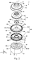
- Fig. 1 is a cross-sectional view of an air blowing device according to the present embodiment.
- Fig. 2 is a disassembled perspective view of the air blowing device according to the present embodiment.
- An air blowing device 1 has a motor 10, an impeller 70, a stator vane member 60, and an impeller housing 80, as illustrated in Fig. 1 and Fig. 2 .
- the stator vane member 60 is attached to the upper side (+Z side) of the motor 10.
- the impeller housing 80 is attached to the upper side of the stator vane member 60.
- the impeller 70 is accommodated between the stator vane member 60 and the impeller housing 80.
- the impeller 70 is attached to the motor 10 rotatably on the central axis J.
- Fig. 3 is a perspective view of the motor according to the embodiment, as viewed from the lower side.
- the motor 10 has a housing 20, a lower lid 22, a rotor 30 that has a shaft 31, a stator 40, a circuit board 50, a lower-side bearing 52a, and an upper-side bearing 52b, as illustrated in Fig. 1 .
- the housing 20 is a covered cylindrical container that accommodates the rotor 30 and stator 40.
- the housing 20 has a cylindrical peripheral wall 21, an upper lid portion 23 situated at the upper end of the peripheral wall 21, and an upper-side bearing holding portion 27 situated at the middle of the upper lid portion 23.
- the stator 40 is fixed on the inner side face of the housing 20.
- the upper-side bearing holding portion 27 is cylindrical in form and protrudes upwards from the middle of the upper lid portion 23.
- the upper-side bearing holding portion 27 holds the upper-side bearing 52b therein.
- Housing-upper-portion through holes 25 and 26 that pass through the housing 20 in the radial direction are provided at the upper portion side of the peripheral wall of the housing 20, as illustrated in Fig. 1 and Fig. 3 .
- Three housing-upper-portion through holes 25 and three housing-upper-portion through holes 26 are provided in the peripheral wall of the housing 20 in an alternating manner around the axis (see Fig. 6 ). According to this configuration, part of air discharged from later-described vents 95 flows into the housing 20, whereby a stator core 41 and coil 42 can be cooled.
- a stepped portion 28 encompassing the upper lid portion 23 around the axis is provided between the peripheral wall 21 and upper lid portion 23 of the housing 20.
- the lower lid 22 is attached to a lower-side (-Z side) opening of the housing 20.
- a cylindrical lower-side bearing holding portion 22c that protrudes toward the lower side from the lower face of the lower lid 22 is provided at the middle of the lower lid 22.
- the lower-side bearing holding portion 22c holds the lower-side bearing 52a.
- Arc-shaped through holes 22a having a width in the radial direction, are provided to the lower lid 22 at three locations around the axis, as illustrated in Fig. 3 .
- Notched portions 22b where the outer peripheral portion of the lower lid 22 has been linearly notched are provided at three positions on the outer peripheral edge of the lower lid 22. Gaps between the opening end 20a at the lower side of the housing 20 and the notched portions 22b are lower-side openings 24 of the motor 10.
- the rotor 30 has the shaft 31, a rotor magnet 33, a lower-side magnet fixing member 32, and an upper-side magnet fixing member 34, as illustrated in Fig. 1 .
- the rotor magnet 33 has a cylindrical shape, and encompasses the shaft 31 around the axis ( ⁇ z direction) at the outer side in the radial direction.
- the lower-side magnet fixing member 32 and upper-side magnet fixing member 34 are cylindrical shapes, having a diameter equivalent to that of the rotor magnet 33.
- the lower-side magnet fixing member 32 and upper-side magnet fixing member 34 are attached to the shaft 31, sandwiching the rotor magnet 33 from both sides in the axial direction.
- the upper-side magnet fixing member 34 has a small radius portion 34a at the upper side portion in the central axis direction, of which diameter is smaller than the lower side (rotor magnet 33 side).
- the shaft 31 is rotatably supported around the axis ( ⁇ z direction) by the lower-side bearing 52a and upper-side bearing 52b.
- the impeller 70 is attached to the end of the shaft 31 at the upper side (+Z side).
- the impeller 70 integrally rotates with the shaft 31 on the axis.
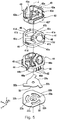
- Fig. 4 is a perspective view of the stator 40 according to the present embodiment.
- Fig. 5 is a disassembled perspective view illustrating the stator 40, circuit board 50, and lower lid 22.
- Fig. 6 is a plane cross-sectional view of the motor 10.
- the stator 40 is positioned on the outer side from the rotor 30 in the radial direction.
- the stator 40 encompasses the rotor 30 around the axis ( ⁇ z direction).
- the stator 40 has a stator core 41, multiple (three) upper-side insulators 43, multiple (three) lower-side insulators 44, and coils 42, as illustrated in Fig. 4 and Fig. 5 .
- the stator core 41 includes a core back portion 41a and multiple (three) teeth portions 41b, as illustrated in Fig. 5 .
- the core back portion 41a is ring-shaped around the center axis.
- the core back portion 41a has a configuration where linear portions 41c at three positions around the axis, and three arc portions 41d, are alternatingly positioned.
- the teeth portions 41b each extend inward in the radial direction from the inner peripheral face of the linear portions 41c.
- the teeth portions 41b are disposed equidistantly in the circumferential direction.
- An inclined member 46 that guides exhaust air into the stator 40 is disposed above each arc portion 41d of the core back portion 41a.
- the inclined members 46 have a shape where the thickness progressively becomes smaller from the outer side in the radial direction toward the inner side.
- the upper-side insulators 43 are insulating members covering part of the upper face and side faces of the stator core 41.
- the upper-side insulators 43 are provided corresponding to each of the three teeth portions 41b.
- the upper-side insulators 43 each have an upper-side outer peripheral wall portion 43a that is positioned at the upper side of the core back portion 41a, an upper-side inner peripheral wall portion 43e that is positioned at the upper side of the tip of the teeth portion 41b, and an upper-side insulating portion 43d that links the upper-side outer peripheral wall portion 43a and upper-side inner peripheral wall portion 43e in the radial direction, and is positioned at the upper side of a portion of the teeth portion 41b where the coil is wound.
- the lower-side insulators 44 are insulating members covering part of the lower face and side faces of the stator core 41.
- the lower-side insulators 44 are provided corresponding to each of the three teeth portions 41b.
- the lower-side insulators 44 each have a lower-side outer peripheral wall portion 44a that is positioned at the lower side of the core back portion 41a, a lower-side inner peripheral wall portion 44c that is positioned at the lower side of the tip of the teeth portion 41b, and a lower-side insulating portion 44b that links the lower-side outer peripheral wall portion 44a and lower-side inner peripheral wall portion 44c in the radial direction, and is positioned at the lower side of a portion of the teeth portion 41b where the coil is wound.
- the upper-side insulators 43 and lower-side insulators 44 are disposed sandwiching the teeth portions 41b of the stator core 41 in the vertical direction.
- the coils 42 are wound on the teeth portions 41b covered by the upper-side insulating portions 43d of the upper-side insulators 43 and the lower-side insulating portions 44b of the lower-side insulators 44.
- the three upper-side outer peripheral wall portions 43a positioned above the core back portion 41a of the stator core 41 encompass the coils 42, at the upper side of the stator core 41.
- the upper-side outer peripheral wall portions 43a each have a first side end face 43b and a second side end face 43c at both ends in the peripheral direction.
- the first side end faces 43b are inclined faces inclined in the radial direction and facing outwards in the radial direction.
- the second side end faces 43c are inclined faces inclined in the radial direction and facing inwards in the radial direction.
- portions situated above the linear portions 41c are upper-side flat faces 43f extending in the axial direction matching the outer peripheral face of the linear portions.
- Arc-shaped faces disposed following the inner peripheral face of the housing 20 are disposed on both sides of the upper-side flat faces 43f in the peripheral direction.
- the upper-side outer peripheral wall portions 43a that are adjacent in the circumferential direction are separated from each other by predetermined gaps, as illustrated in Fig. 6 .
- the first side end face 43b of one upper-side outer peripheral wall portion 43a and the second side end face 43c of the other upper-side outer peripheral wall portion 43a face each other in the circumferential direction.
- the degree of inclination of the first side end face 43b in the radial direction and the degree of inclination of the second side end face 43c in the radial direction differ.
- the width of opening portions 90 at the outer side in the radial direction from gaps CL formed between adjacent upper-side outer peripheral wall portions 43a in the peripheral direction is narrower than the width in the peripheral direction of opening portions 91 at the inner side in the radial direction.
- the inclined members 46 disposed above the core back portion 41a.
- the inclined members 46 are sandwiched between the first side end faces 43b and second side end faces 43c.
- the gaps CL are situated on the inner side of the housing-upper-portion through holes 26 of the housing 20.
- the housing-upper-portion through holes 26 and the gaps CL make up airflow paths guiding exhaust air flowing in from the outer side of the housing 20 to the inner side of the stator 40.
- the direction of inclination of the gaps CL in the radial direction as viewed from above matches the direction of flow of exhaust air discharged from the stator vane member 60 in the peripheral direction. That is to say, this matches the direction of rotation of the impeller 70.
- the opening portions 90 at the inlet side of the gaps CL are formed relatively large, so a greater amount of exhaust air can be suctioned in from the housing-upper-portion through holes 26, while the widths of the opening portions 91 are relatively narrow, so air discharged from the gaps CL can be caused to flow to the intended positions (coils 42) more accurately, as illustrated in Fig. 6 . Accordingly, the stator core 41 and coils 42 can be cooled more efficiently by the air flowing in from the housing-upper-portion through holes 26.
- the three lower-side outer peripheral wall portions 44a positioned at the lower side from the core back portion 41a encompass the coils 42 at the lower side of the stator core 41. Although there are gaps between lower-side outer peripheral wall portions 44a that are adjacent in the circumferential direction, the lower-side outer peripheral wall portions 44a may be in contact with each other in the circumferential direction.
- the portions positioned at the lower side from the linear portions 41c of the core back portion 41a are lower-side flat faces 44d extending in the axial direction matching the outer peripheral face of the linear portions 41c. At both sides in the peripheral direction of the lower-side flat faces 44d, arc-shaped faces are provided having been disposed following the inner peripheral face of the housing 20.
- plate portions 45 that extend in the axial direction are provided to the lower-side flat faces 44d.
- the plate portions 45 are erected approximately perpendicular to the lower-side flat faces 44d, as illustrated in Fig. 6 .
- the tips of the plate portions 45 at the outer side in the radial direction reach the inner peripheral face of the housing 20.
- the plate portions 45 section the region between the lower-side outer peripheral wall portion 44a and the housing 20 into multiple regions in the circumferential direction.
- the circuit board 50 is disposed between the stator 40 and the lower lid 22, as illustrated in Fig. 1 and Fig. 6 .
- the circuit board 50 has a circular ring-shaped main unit portion 50a, and three protruding portions 50b that protrude toward the outer side from the outer edge of the main unit portion 50a, in a direction inclined as to the radial direction.
- the main unit portion 50a has a hole through which the shaft 31 is passed.
- the circuit board 50 is fixed to the lower-side insulators 44.
- the circuit board 50 has at least three rotary sensors 51 mounted thereupon, as illustrated in Fig. 6 .
- the rotary sensors 51 are Hall effect sensors, for example.
- the circuit board 50 may be electrically connected to the coils 42.
- a driving circuit that outputs driving signals to the coils 42 may be mounted on the circuit board 50.
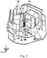
- Fig. 7 is an explanatory diagram illustrating a mounting state of a rotary sensor 51.
- the rotary sensors 51 are disposed interposed between tip portions of lower-side inner peripheral wall portions 44c that are adjacent in the circumferential direction, as illustrated in Fig. 6 and Fig. 7 .
- the three rotary sensors 51 are equidistantly disposed every 120° in the circumferential direction.
- the faces of the rotary sensors 51 on the inner side in the radial direction face the rotor magnet 33.
- the rotor magnet 33 is disposed at the center portion of the rotor 30 in the axial direction in the case of the present embodiment. Accordingly, the rotary sensors 51 are connected to the circuit board 50 by leads 51a of a length corresponding to the length from the circuit board 50 to the rotor magnet 33 in the axial direction.
- the length of the motor 10 in the axial direction can be reduced by three rotary sensors 51 being disposed interposed between the tip portions of lower-side inner peripheral wall portions 44c that are adjacent in the circumferential direction, as compared to a structure where sensor magnets are disposed below the lower-side magnet fixing member 32 and the rotary sensors 51 are disposed further below the sensor magnets, for example.
- a mechanism that supports the rotary sensors 51 may be provided to the tip portion of the lower-side inner peripheral wall portions 44c.
- recesses may be provided into which the rotary sensors 51 are inserted, thereby suppressing movement of the rotary sensors 51 in the radial direction.
- the rotary sensors 51 may be fixed to the lower-side inner peripheral wall portions 44c by snap-fitting or the like.
- the lower lid 22 is attached to the opening end 20a of the housing 20 accommodating the stator 40 and circuit board 50. At least part of the three through holes 22a of the lower lid 22 are situated further on the outer side in the radial direction than the outer peripheral edge of the main unit portion 50a of the circuit board 50.
- the notched portions 22b at the outer periphery of the lower lid 22 are disposed approximately matching the linear portions 41c of the stator core 41, the upper-side flat faces 43f of the upper-side insulators 43, and the lower-side flat faces 44d of the lower-side insulators 44, as viewed in the axial direction.
- the lower-side openings 24 at the lower face of the motor 10 serve as vents of the air flow paths FP between the stator 40 and housing 20.
- stator vane member 60 the stator vane member 60, impeller 70, and impeller housing 80 will be described.
- Fig. 7 is a perspective view of the stator vane member 60 as viewed from below.
- Fig. 8 is a cross-sectional view where a part of the impeller 70, stator vane member 60, and impeller housing 80 are illustrated enlarged.
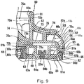
- Fig. 9 is a partial side view of the stator vane member 60.
- the stator vane member 60 has a first stator vane member 61a, and a ring-shaped cover portion 61b, as illustrated in Fig. 1 and Fig. 2 .
- the first stator vane member 61a and ring-shaped cover portion 61b are attached to the upper face of the motor 10, having been layered in the axial direction.
- the first stator vane member 61a has a lower-portion stator vane supporting ring 62, an attachment ring 63, three linking portions 64, and multiple lower-portion stator vanes 67b.
- the lower-portion stator vane supporting ring 62 and attachment ring 63 are disposed coaxially, and are linked by the three linking portions 64 extending in the radial direction.
- the three linking portions 64 are disposed at equidistant intervals of 120° each in the peripheral direction.
- the linking portions 64 have through holes 64a that pass through in the axial direction.
- Three through holes 64a are disposed at equidistant intervals of 120° each in the peripheral direction.
- the attachment ring 63 has a recessed groove 63a on the upper face thereof, that is concentric with the attachment ring 63.
- the multiple lower-portion stator vanes 67b protrude toward the outer side in the radial direction from the outer peripheral face of the lower-portion stator vane supporting ring 62.
- the multiple lower-portion stator vanes 67b are disposed equidistantly in the peripheral direction.
- the outer peripheral face of the lower-portion stator vane supporting ring 62 is a tapered form that tapers toward the upper side.
- the lower-portion stator vanes 67b have shapes that increase in width in the radial direction the further toward the upper side.
- the ring-shaped cover portion 61b has a disc-ring shaped ring-shaped cover flat face portion 66a, a cylindrical upper-portion stator vane supporting ring 66b extending to the lower side from the outer peripheral edge of the ring-shaped-cover flat face portion 66a, multiple upper-portion stator vanes 67a, an outer perimeter ring 65 connected to the outer side of the upper-portion stator vanes 67a ion the radial direction, and a ring-shaped protruding portion 66c that protrudes upward from the outer peripheral edge of the ring-shaped cover flat face portion 66a.
- the multiple upper-portion stator vanes 67a link the outer peripheral face of the upper-portion stator vane supporting ring 66b and the inner peripheral face of the outer perimeter ring 65.
- the upper-portion stator vane supporting ring 66b has a stepped portion 66d that extends the full circumference of the outer peripheral side of the lower end portion thereof.
- the ring-shaped cover flat face portion 66a has an attachment ring 68 that extends downwards from the lower face at the middle portion, and three columnar protruding portions 69 that protrude downwards from the lower face of the ring-shaped-cover flat face portion 66a, as illustrated in Fig. 8 .
- the attachment ring 68 has a cylindrical cylinder portion 68a, and a ring-shaped protruding portion 68b that protrudes downwards from the outer peripheral portion in the radial direction of the lower end face of the cylinder portion 68a.
- the three columnar protruding portions 69 have the same diameters and heights, and are equidistantly disposed every 120° in the circumferential direction.
- the columnar protruding portions 69 are hollow in the present embodiment, and each have a through hole 69b at the middle of an end face 69a at the lower side that passes through in the axial direction.
- the upper-side bearing holding portion 27 of the motor 10 is inserted into the attachment ring 63 of the first stator vane member 61a, as illustrated in Fig. 1 and Fig. 9 .
- the lower end face of the lower-portion stator vane supporting ring 62 of the first stator vane member 61a comes into contact with a stepped face 28a facing upwards on the stepped portion 28 of the motor 10.
- the ring-shaped cover portion 61b is attached to the first stator vane member 61a.
- the upper-side bearing holding portion 27 is inserted into the attachment ring 68 of the ring-shaped cover portion 61b, as illustrated in Fig. 9 .
- the protruding portion 68b at the lower side tip of the attachment ring 68 is fit into the recessed groove 63a of the first stator vane member 61a.
- the stepped portion 66d of the upper-portion stator vane supporting ring 66b of the ring-shaped cover portion 61b is fit to an upper side opening end of the lower-portion stator vane supporting ring 62.
- the outer peripheral face of the upper-portion stator vane supporting ring 66b and the outer peripheral face of the lower-portion stator vane supporting ring 62 are smoothly connected in the vertical direction.
- the columnar protruding portions 69 of the ring-shaped cover portion 61b are inserted into the through holes 64a of the first stator vane member 61a.
- the end faces 69a of the columnar protruding portions 69 come into contact with the upper face of the upper lid portion 23 of the motor 10.
- the ring-shaped cover portion 61b and the motor 10 are fastened to each other, by bolts BT inserted through the through holes 69b of the columnar protruding portions 69 and screw holes 23a of the upper lid portion 23.
- the first stator vane member 61a is positioned in the peripheral direction by the columnar protruding portions 69 of the ring-shaped cover portion 61b, and is fixed to the motor 10 by being pressed by the attachment ring 68 and upper-portion stator vane supporting ring 66b of the ring-shaped cover portion 61b.
- the stator vane member 61 is configured of two members (first stator vane member 61a and ring-shaped cover portion 61b), while only the ring-shaped cover portion 61b is fastened to the metal housing 20 of the motor 10 in the present embodiment.
- This fixing arrangement enables trouble to be suppressed from occurring in the state of fastening between the motor 10 and stator vane member 60 when change in temperature of the air blowing device 1 occurs.
- both of the first stator vane member 61a and ring-shaped cover portion 61b are fixed to the motor 10 by common bolts BT being passed through, the bolts BT fasten down the two resin members, and the amount of change in volume due to temperature change increases. Accordingly, there is concern that the stator vane member 60 will shrink in low-temperature environments, creating looseness.
- the end faces 69a of the columnar protruding portions 69 of the ring-shaped cover portion 61b are brought into contact with the housing 20 and fastened by the bolts BT, so the thickens of the resin member fastened by the bolts BT can be reduced. Accordingly, the amount of change in volume when temperature changes is smaller, thereby enabling loosening of the fastening to be suppressed.
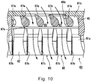
- Fig. 10 is a side view of the stator vane member 60.
- the same number of upper-portion stator vanes 67a and lower-portion stator vanes 67b are arrayed in the peripheral direction, as illustrated in Fig. 10 .
- the upper-portion stator vanes 67a and lower-portion stator vanes 67b correspond one on one, and are disposed arrayed in the axial direction.
- the angle of inclination as to the axial direction of the upper-portion stator vanes 67a is greater than the angle of inclination as to the axial direction of the lower-portion stator vanes 67b.
- the upper-portion stator vanes 67a are disposed inclined at a relatively great angle, in order to cause exhaust air that flows in a direction inclined to the rotation direction of the impeller 70 to efficiently flow in between the upper-portion stator vanes 67a.
- the lower-portion stator vanes 67b guide the exhaust air downwards, so that exhaust air discharged from the vents 95 does not flow outwards in the radial direction.
- a gap 67c is a gap that extends in the horizontal direction in the present embodiment, but may be a gap that extends in an oblique direction as to the horizontal direction.
- the direction preferably is the same as the direction of inclination of the upper-portion stator vanes 67a. Providing such an oblique-direction gap results in exhaust air passing through the gap, and an entire exhaust air flow path 93 can be effectively used.
- the exhaust air flow path 93 shifts toward the outer side in the radial direction near the vents 95 in the present embodiment, as illustrated in Fig. 9 . That is to say, the outer peripheral face of the lower-portion stator vane supporting ring 62 of the first stator vane member 61a is tapered in shape, with the diameter increasing toward the lower side.
- a lower ring 65b facing toward the lower-portion stator vane supporting ring 62 in the radial direction has a skirt-like shape where the inner circumference diameter increases toward the lower side.
- the exhaust air flow path 93 spreads more to the outer side in the radial direction the lower the position is, with the width in the radial direction unchanged.
- the horizontal cross-sectional area of the exhaust air flow path 93 gradually increases the closer to the vents 95. This enables exhaust noise at the time of air being discharged from the vents 95 to be reduced.
- the impeller 70 discharges fluid suctioned from an intake port 70a that is opened toward the upper side, toward the outer side in the radial direction via internal flow paths.
- the impeller 70 has an impeller main body 71 and an impeller hub 72.
- the impeller main body 71 has a base portion 73, multiple moving blades 74, and a shroud 75.
- the base portion 73 is disc-shaped, and has a through hole 73a passing through in the axial direction at the middle portion.
- the perimeter of the through hole 73a of the base portion 73 is an inclined portion 73b that has a conical face shape extending at the upper side.
- the moving blades 74 are plate-shaped members curved in the circumferential direction, that extend from the inner side in the radial direction toward the outer side on the upper face of the base portion 73.
- the moving blades 74 are disposed erected following the axial direction.
- the shroud 75 is a cylindrical shape that tapers toward the upper side in the axial direction. An opening portion at the middle of the shroud 75 is the intake port 70a of the impeller 70.
- the base portion 73 and shroud 75 are linked by the moving blades 74.
- Fig. 11 is a plan view of the moving blades 74 of the impeller 70.
- the multiple moving blades 74 are disposed following the circumferential direction ( ⁇ Z direction) on the upper face of the base portion 73, as illustrated in Fig. 11 .
- the moving blades 74 are erected perpendicularly from the upper face of the base portion 73 following the axial direction, as illustrated in Fig. 1 .
- three types of moving blades 74 are disposed, with the same types of moving blades being equidistantly disposed in the circumferential direction.
- the multiple moving blades 74 in the present embodiment include multiple (three) first moving blades 74a, multiple (three) second moving blades 74b, and multiple (six) third moving blades 74c.
- the three first moving blades 74a are disposed at equidistantly every 120° in the circumferential direction.
- the second moving blades 74b are each disposed at intermediate positions between first moving blades 74a adjacent in the circumferential direction.
- the three second moving blades 74b are also disposed equidistantly every 120° in the circumferential direction.
- the third moving blades 74c are each disposed at intermediate positions between first moving blades 74a and second moving blades 74b adjacent in the circumferential direction.
- the six third moving blades 74c are disposed equidistantly every 60° in the circumferential direction.
- the moving blades 74 extend on the upper face of the base portion 73 having a curvature in plan view (XY plane view). One end of each moving blade 74 is positioned on an outer peripheral edge of the base portion 73. The other end of each moving blade 74 is positioned further on the inner side than the outer peripheral edge of the base portion 73 in the radial direction.
- each of the first moving blades 74a, the second moving blades 74b, and the third moving blades 74c, at the outer side in the radial direction, are all positioned on the outer edge of the base portion 73.
- end portions P1 of the first moving blades 74a on the inner peripheral side are positioned closest to the center of the base portion 73.
- End portions P2 of the second moving blades 74b on the inner peripheral side are positioned on the outer side in the radial direction from the end portions P1 of the first moving blades 74a.
- End portions P3 of the third moving blades 74c on the inner peripheral side are positioned further on the outer side in the radial direction from the end portions P2 of the second moving blades 74b. This configuration enables turbulence within the impeller 70 to be reduced, so the air blowing efficiency of the impeller 70 is improved.
- the first moving blades 74a, the second moving blades 74b, and the third moving blades 74c, each have a shape that is curved like a bow in a counterclockwise direction.
- the first moving blades 74a are each formed of four arcs that are different in radius of curvature.
- a projecting blade face 74d of the first moving blades 74a has three inflection points CP11, CP12, and CP13, in the longitudinal direction.
- the second moving blades 74b are each formed of three arcs that are different in radius of curvature.
- a projecting blade face 74e of the second moving blades 74b has two inflection points CP21 and CP22 in the longitudinal direction.
- the third moving blades 74c are each formed of two arcs that are different in radius of curvature.
- a projecting blade face 74f of the third moving blades 74c has one inflection point CP31 in the longitudinal direction.
- the inflection point CP11 of each first moving blade 74a, the inflection point CP21 of each second moving blade 74b, and the inflection point CP31 of each third moving blade 74c are each disposed at the same radius position C1 on the base portion 73. Further, the radius of curvature of a portion of each first moving blade 74a that is further on the outer side of the radial position C1, the radius of curvature of a portion of each second moving blade 74b that is further on the outer side of the radial position C1, and the radius of curvature of a portion of each third moving blade 74c that is further on the outer side of the radial position C1, are the same as each other.
- the inflection point CP12 of each first moving blade 74a, the inflection point CP22 of each second moving blade 74b, and the end portion P3 of each third moving blade 74c are each disposed at the same radius position C2 on the base portion 73. Further, the radius of curvature of a portion of each first moving blade 74a between the radial positions C1 and C2, the radius of curvature of a portion of each second moving blade 74b between the radial positions C1 and C2, and the radius of curvature of a portion of each third moving blade 74c between the radial positions C1 and C2, are the same as each other.
- each first moving blade 74a and the end portion P2 of each second moving blade 74b are disposed at the same radius position C3 on the base portion 73. Further, the radius of curvature of a portion of each first moving blade 74a between the radial positions C2 and C3 and the radius of curvature of a portion of each second moving blade 74b between the radial positions C2 and C3 are the same as each other.
- the radii of curvature of the blade faces 74d to 74f of the moving blades 74 (74a through 74c) in the present embodiment are different for each region of the impeller 70 in the radial direction. Meanwhile, portions of different types of moving blades 74 (the first moving blades 74a through third moving blades 74c) that belong to the same region in the radial direction are set to have the same radius of curvature.
- the radial position C3 agrees with the intake port 80a of the impeller housing 80 as seen in the axial direction. Accordingly, only the portions of the first moving blades 74a further on the inner peripheral side than the inflection point CP13 are disposed inward of the intake port 80a.
- the impeller hub 72 includes a cylindrical portion 72a that extends in the axial direction, a disc-shaped flange portion 72b that extends outwards in the radial direction from the lower portion of the outer peripheral face of the cylindrical portion 72a, and multiple projecting portions 72c that protrude upwards from the upper face of the flange portion 72b.
- the cylindrical portion 72a includes a tapered inclined face portion 72d that becomes tapered toward the tip portion at the upper side.
- the impeller hub 72 is attached to the impeller main body 71 by inserting the cylindrical portion 72a into the through hole 73a of the base portion 73 from the lower side.
- the cylindrical portion 72a may be press-fitted into the through hole 73a, or may be fixed using an adhesive agent or the like.
- the flange portion 72b of the impeller hub 72 supports the impeller main body 71 from the lower side.
- the projecting portions 72c on the flange portion 72b are fitted into recesses 73c on the lower face of the base portion 73. Fitting the projecting portions 72c into the recesses 73c restricts relative movement of the impeller main body 71 and the impeller hub 72 in the circumferential direction.
- the flange portion 72b can support the impeller main body 71 over a wide area in the radial direction from below. Accordingly, the impeller 70 can be held in a stable manner, and stability at the time of high-speed rotation is raised. That is to say, the flange portion 72b can support the impeller main body 71 over a wide area in the radial direction from below, so deviation as to the shaft 31 of the impeller 70 can be reduced.
- the inclined face portion 72d at the tip of the cylindrical portion 72a of the impeller hub 72 and the inclined face portion 73b of the base portion 73 are smoothly connected to each other in the vertical direction in the impeller 70.
- the inclined face portion 72d and the inclined face portion 73b make up a ring-shaped inclined face 70b that guides fluid suctioned from the intake port 70a of the impeller 70 to the outer side in the radial direction.
- Configuring the ring-shaped inclined face 70b from the impeller main body 71 and the impeller hub 72 enables the maximum height of the ring-shaped inclined face 70b to be increased by increasing the length of the cylindrical portion 72a (inclined face portion 72d) without increasing the height of the inclined face portion 73b of the base portion 73. Accordingly, a ring-shaped inclined face 70b having a preferable shape can be realized while suppressing increase in thickness of the base portion 73.
- the impeller hub 72 is preferably made of metal.
- the shaft 31 and the impeller 70 can be strongly linked to each other. Accordingly, the impeller 70 can be rotated at high speeds in a stable manner.
- a metal face can be used as the inclined face portion 72d, and accordingly the surface of the upper tip of the ring-shaped inclined face 70b can be smoothed.
- the impeller 70 is fixed to the shaft 31 by fitting the upper end portion of the shaft 31 into the cylindrical portion 72a of the impeller hub 72 from the lower side. As illustrated in Fig. 1 and Fig. 9 , the impeller 70 connected to the shaft 31 is disposed at the inner side of the ring-shaped protruding portion 66c of the ring-shaped cover portion 61b. Accordingly, the protruding portion 66c is disposed nearby a vent 70c of the impeller 70.
- the protruding portion 66c guides exhaust air discharged from the impeller 70 to the lower side, along with a later-described exhaust air guide 83 of the impeller housing 80.
- the outer peripheral face of the protruding portion 66c is an inclined face 66e that is progressively inclined downwards toward on the outer side in the radial direction.
- the outer peripheral face of the protruding portion 66c is a smooth convex curved shape toward the outer side.
- the lower end of the outer peripheral face of the protruding portion 66c is smoothly connected to the outer peripheral face of the cylindrical upper-portion stator vane supporting ring 66b. Accordingly, the inclination angle as to the horizontal direction at the lower end of the protruding portion 66c is approximately 90°.
- the upper end of the protruding portion 66c is positioned on the immediately outer side in the radial direction of the outer peripheral edge of the base portion 73 of the impeller 70.
- the upper end of the protruding portion 66c is positioned at the upper side from the lower face of the base portion 73, but is positioned at the lower side from the upper face of the outer peripheral edge of the base portion 73.
- air discharged from the impeller 70 can be smoothly guided downwards without turbulence in the flow, due to the protruding portion 66c having the above-described shape and placement.
- air is discharged from the outer peripheral edge of the base portion 73 in an approximately horizontal direction.
- the upper end of the protruding portion 66c is at a position lower than the upper face of the base portion 73 in the present embodiment, so the discharged air is guided following the outer peripheral face of the protruding portion 66c without colliding with the protruding portion 66c. Accordingly, air can be conveyed efficiently.
- providing the protruding portion 66c enables air that has been emitted to the outer side in the radial direction from the vent 70c to flow into the gap in the axial direction between the ring-shaped cover portion 61b and base portion 73.
- the impeller housing 80 has the intake port 80a on the upper side, and has the shape of a cylinder that is tapered toward the upper side in the axial direction.
- the impeller housing 80 has an intake guide portion 81 positioned at the opening end of the intake port 80a, an impeller housing main body 82 that accommodates the impeller 70, and a skirt-like exhaust air guide portion 83 that extends from the outer peripheral edge of the impeller housing main body 82 toward in the radial direction and downwards.
- the impeller housing main body 82 has a cross-sectional shape modeled after that of the shroud 75 of the impeller 70.
- the inner face (lower face) of the impeller housing main body 82 faces the outer face (upper face) of the shroud 75 across a uniform spacing.
- the ring-shaped intake guide portion 81 that protrudes toward the inner side in the radial direction is positioned on the upper end of portion the inner peripheral side of the impeller housing main body 82.
- the intake guide portion 81 covers an upper end face 75b of the shroud 75 from above, as illustrated in Fig. 9 .
- a narrow gap runs in the radial direction between the lower face of the intake guide portion 81 and the upper end face 75a of the shroud 75.
- An outer-peripheral-side end portion 82a of the impeller housing main body 82 is bent to wrap around the outer peripheral end of the shroud 75 to the lower side.
- a narrow gap extending to the upper side in the axial direction runs between the inner peripheral face of the outer-peripheral-side end portion 82a and the outer side end face of the shroud 75.
- the exhaust air guide portion 83 has a stepped portion 83a at the lower face that extends the full circumference on the inner side in the radial direction.
- the stepped portion 83a is fit into a stepped portion 65a of the outer perimeter ring 65 of the ring-shaped cover portion 61b, as illustrated in Fig. 9 .
- the inner peripheral face of the exhaust air guide portion 83 and the inner peripheral face of the outer perimeter ring 65 are smoothly connected in the vertical direction, making up a wall face on the outer peripheral side of the exhaust air flow path.
- the inner peripheral face of the exhaust air guide portion 83 along with the outer peripheral face of the protruding portion 66c of the ring-shaped cover portion 61b situated at the lower side of the impeller 70, makes up an exhaust air flow path 92 that guides exhaust air, discharged to the outer side in the radial direction from the impeller 70, to the lower side.
- the exhaust air guide portion 83 has a guide-portion inner-side recessed portion 83b and a guide-portion outer-side protruding portion 83c.
- the guide-portion inner-side recessed portion 83b is a portion where the inner peripheral face is recessed.
- the guide-portion inner-side protruding portion 83c is a portion situated at the lower side from the guide-portion inner-side recessed portion 83b and where the inner peripheral face bulges.
- the distance between the inclined face 66e and the inner peripheral face of the exhaust air guide portion 83 is the shortest at the region where the guide-portion inner-side protruding portion 83c and the inclined face 66e face each other. Accordingly, the efficiency of the air blowing device 1 is improved. That is to say, when air is discharged to the outer side in the radial direction by the impeller 70, the air passes through the region where the distance between the inclined face 66e and the inner peripheral face of the exhaust air guide portion 83 is the shortest.
- the cross-sectional are of the flow path is locally narrow at this region, so static pressure of the airflow rises in this region, and separation of airflow at the inner peripheral face of the exhaust air guide portion 83 and at the inclined face 66e is reduced. Accordingly, occurrence of turbulence within the flow path formed between the inclined face 66e and the inner peripheral face of the exhaust air guide portion 83 is suppressed, and air can be efficiently guided within the flow path, so the efficiency of the air blowing device 1 can be improved.
- the exhaust air flow path 92 is connected to the exhaust air flow path 93 of the stator vane member 60, as illustrated in Fig. 9 .
- the exhaust air flow path 93 of the stator vane member 60 is made up of flow paths between the upper-portion stator vanes 67a and flow paths between the lower-portion stator vanes 67b, as illustrated in Fig. 10 .
- the portions where the exhaust air flow path 93 connects to the outside are the vents 95.
- the air blowing device 1 draws air into the impeller 70 from the intake 80a by rotating the impeller 70 by the motor 10, and discharges air to the outer side in the radial direction via air flow paths within the impeller 70, as illustrated in Fig. 1 .
- the exhaust air discharged from the impeller 70 passes through the exhaust air flow path 92 and flows in between the upper-portion stator vanes 67a.
- the upper-portion stator vanes 67a rectify and discharge the exhaust air downwards.
- the lower-portion stator vanes 67b guides the exhaust air to the outer side in the radial direction, while directing the flow direction downwards. Thereafter, the exhaust air is externally discharged from the air blowing device 1 through the vents 95.
- Part of the exhaust air discharged downwards from the vents 95 follows the outer peripheral face of the housing 20 of the motor 10 and flows to the lower side. Another part of the exhaust air discharged from the vents 95 flows into the inside of the motor 10 from the housing-upper-portion through holes 25 and 26 provided to the housing 20.
- the exhaust air flows downstream through the flow paths FP.
- the outer peripheral faces of the linear portions 41c (stator core 41) are exposed within the flow paths FP as illustrated in Fig. 4 , and are cooled by the exhaust air.
- Multiple plate portions 45 are situated within the air flow paths FP, and rectify the exhaust air flowing through the flow paths FP. According to this configuration, the blowing efficiency of the exhaust air flowing through the air flow paths FP is improved.
- the exhaust air that has flowed through the air flow paths FP is discharged downwards from the lower-side openings 24 of the motor 10.
- the first side end face 43b and second side end face 43c and the inclined member 46 making up the gaps CL guide the exhaust air passing through the gaps CL to the side faces of the coils 42. That is to say, a situation where the exhaust air passing through the gaps CL strikes the upper face of the arc portions 41d and reduces exhaust efficiency can be reduced as compared with a case where no inclined member 46 is provided.
- the coils 42 which are heat generators in the motor 10, can be efficiently cooled.
- the exhaust air flows downwards around the coils 42, and is emitted downwards from the through holes 22a at the lower face of the motor 10.
- the vents 95 that are ring shaped around the axis are disposed above the motor 10. Accordingly, there is no need to provide air flow path members for exhausting to the motor 10 on the outer peripheral side in the radial direction. As a result, a motor 10 having a larger diameter can be used, and the air blowing capabilities of the air blowing device 1 can be improved without increasing the diameter thereof. Alternatively, the size of the air blowing device 1 can be reduced while maintaining the same air blowing capabilities.
- vent 95 it is sufficient for the vent 95 to be situated further upwards from the stator 40.
- the relationship between the capabilities of the motor 10 and the diameter is decided by the size of the stator 40, so the vents 95 can be disposed on the inner side of the diameter of the motor 10 as long as the vents 95 are disposed further upwards from the stator 40.
- the air blowing device 1 has three gaps CL and three air flow paths FP. According to this configuration, the stator core 41 and coils 42 can be efficiently cooled by air flowing in to the inner side in the radial direction from the gaps CL, and the stator core 41 can be cooled by air flowing through the flow paths FP in the axial direction.
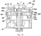
- Fig. 12 is a longitudinal-section view of an air blowing device 101 according to a modification of the above-described exemplary embodiment.
- components that are the same as those in the above-described embodiment are denoted by the same reference symbols, and description thereof will be omitted.
- the air blowing device 101 has the motor 10, a ring-shaped cover portion 166, the impeller 70, and an impeller housing 180.
- the motor 10 has the shaft 31 disposed following the central axis J extending in the vertical direction.
- the outer edge of the motor 10 in the radial direction is situated further to the outer side in the radial direction as compared to the outer edge of the impeller 70 in the radial direction.
- the impeller 70 is fixed to the shaft 31.
- the impeller 70 has the base portion 73, the shroud 75, and the multiple moving blades 74.
- the base portion 73 is a flat plate-shaped member that extends in a direction orthogonal to the shaft 31.
- the shroud 75 is positioned above the base portion 73 and opens upwards.
- the multiple moving blades 74 are connected to the base portion 73 and the shroud 75, and are arrayed in the circumferential direction.
- the impeller housing 180 encompasses an upper side and the outer side of the impeller 70 in the radial direction.
- the impeller housing 180 includes an exhaust air guide portion 183.
- the exhaust air guide portion 183 extends outwards in the radial direction and downwards being positioned outward of the outer edge of the impeller 70 in the radial direction.
- the impeller housing 180 includes a vent 195 at the upper side from the lower end portion of the ring-shaped cover portion 166. Therefore, in a case where the vent 195 is positioned at the upper side from the motor 10, air blowing efficiency of the air blowing device 101 can be improved even in a case where the length of a flow path configured between a later-described inclined face 166e and the inner peripheral face of the exhaust air guide portion 183 is short.
- a region can be configured in the flow path where the cross-sectional area of the flow path becomes locally small, so static pressure of the airflow rises in this region, and occurrence of turbulence due to separation of air in the flow path can be reduced.
- the ring-shaped cover portion 166 is positioned at the upper side from the motor 10 in the axial direction.
- the ring-shaped cover portion 166 includes a ring-shaped cover flat face portion 166a and a protruding portion 166c.
- the ring-shaped cover flat face portion 166a extends in a direction orthogonal to the shaft 31 and faces the base portion 73 in the axial direction.
- the protruding portion 166c protrudes upwards from the ring-shaped cover flat face portion 166a, further on the outer side of the outer edge of the impeller 70 in the radial direction.
- the protruding portion 166c has the inclined face 166e.
- the inclined face 166e progressively inclines downwards as the outer peripheral face heads toward the outer side in the radial direction.
- the position of the inner edge of the protruding portion 166c in the radial direction, and the position of the inner edge of the exhaust air guide portion 183 in the radial direction, are the same. That is to say, the exhaust air guide portion 183 smoothly curves toward the outer side in the radial direction and downwards, from the inner end toward the outer side.
- the inclined face 166e of the protruding portion 166c also smoothly curves toward the outer side in the radial direction and downwards from the inner end toward the outer side.
- air discharged from the impeller is smoothly guided to the outer side in the radial direction and downwards, by the exhaust air guide portion 183 and the inclined face 166e. Accordingly, occurrence of air turbulence can be reduced near the inner peripheral face of the impeller housing 180 and near the inclined face 166e, so the air blowing efficiency of the air blowing device 101 is improved.
- the exhaust air guide portion 183 includes a guide-portion inner-side recessed portion 183b and a guide-portion inner-side protruding portion 183c.
- the guide-portion inner-side recessed portion 183b is a portion of which the inner peripheral face is recessed.
- the guide-portion inner-side protruding portion 183c is positioned at the lower side from the guide-portion inner-side recessed portion 183b, and is a portion of which the inner peripheral face bulges.
- the distance between the inclined face 166e and the inner peripheral face of the exhaust air guide portion 183 is shortest at a region in which the guide-portion inner-side protruding portion 183c and the inclined face 166e face each other. Accordingly, the efficiency of the air blowing device 101 is improved.
- the air blowing device 101 includes an inward vent 196.
- the vent 195 and the inward vent 196 are alternately disposed in the circumferential direction. Part of air discharged toward the outer side in the radial direction by the impeller 70 passes through the flow path and is discharged toward the outer side in the radial direction via the vent 195. Meanwhile, another part of the air discharged toward the outer side in the radial direction by the impeller 70 passes through the flow path and is guided into the inner side of the motor 10 via the inward vent 196.
- the ring-shaped cover portion 166 includes a ring-shaped cover connection portion 166f between the vent 195 and the inward vent 196. At least part of the ring-shaped cover connection portion 166f is fixed. That is to say, at least part of the impeller housing 180 and at least part of the ring-shaped cover portion 166 are fixed. Accordingly, the impeller housing 180 and the ring-shaped cover portion 166 can be assembled with high precision. That is to say, the positional relationship between the inner peripheral face of the impeller housing 180 and the ring-shaped cover portion 166 can be managed in a highly precise manner.
- the sectional area of the flow path configured between the inner peripheral face of the impeller housing 180 and the inclined face 166e can be configured with high precision, so occurrence of uneven air pressure in the flow path can be reduced. Also, vibrations of the impeller housing 180 can be reduced.
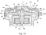
- Fig. 13 is a longitudinal-section view of an air blowing device 201 according to an exemplary third embodiment of the present invention.
- Components of the air blowing device 201 according to the third embodiment that are the same as those of the above-described air blowing device 1 or air blowing device 101 may be denoted by the same reference symbols, and description thereof may be omitted.
- the air blowing device 201 has a motor 210, a ring-shaped cover 261b, an impeller 270, and an impeller housing 280.
- the motor 210 has a shaft 231 that is disposed following the central axis J extending in the vertical direction.
- the motor 210 is an outer rotor type, but may be an inner rotor type.
- the impeller 270 is fixed to the shaft 231.
- the impeller 270 is rotatably supported on the central axis J by a lower-side bearing 252a and upper-side bearing 252b.
- the impeller 270 has a base portion 273 and moving blades 274.
- the base portion 273 extends in a direction orthogonal to the shaft 231. Note however, that a member of the base portion 273 at the outer side in the radial direction has a plate-like form extending in a direction orthogonal to the shaft 231, and a member on the inner side in the radial direction is an inclined face that smoothly spreads toward the lower side in the radial direction, the farther away from the inner side toward the outer side.
- the fluid emitted by the impeller 270 can be smoothly guided to the outer side in the radial direction.
- the entire base portion 273 may have a plate-like form extending in a direction orthogonal to the shaft 231, or the entirety may be a curved face that smoothly spreads toward the lower side in the radial direction, the farther away from the inner side toward the outer side.
- Multiple moving blades 274 are connected to the base portion 273 and arrayed in the peripheral direction.
- the moving blades 274 may be formed as an integral member with the base portion 273, or may be formed as separate members.
- the impeller housing 280 encompasses above the impeller 270 and the outer side thereof in the radial direction.
- the impeller housing 280 has an exhaust air guide portion 283 that extends toward the outer side in the radial direction and downwards, further on the outer side from the outer edge of the impeller 270 in the radial direction.
- the exhaust air guide portion 283 has a guide-portion inner-side recessed portion 283b and a guide-portion inner-side protruding portion 283c.
- the guide-portion inner-side recessed portion 283b is a portion where the inner face is recessed toward the outer side in the radial direction.
- a radial-direction inner end 283d on the inner face of the exhaust air guide portion is disposed further on the outer side from the outer edge of the impeller 270 in the radial direction.
- the guide-portion inner-side recessed portion is a member disposed further on the outer side from the outer edge of the impeller 270 in the radial direction, with the inner face thereof bulging toward the inner side in the radial direction.
- the guide-portion inner-side protruding portion 283c is a portion situated at the outer side in the radial direction and the lower side in the axial direction from the guide-portion inner-side recessed portion 283b.
- the ring-shaped cover 261b is situated above the motor 210 in the axial direction.
- the ring-shaped cover 261b corresponds to the ring-shaped cover portions 61b and 116 in the above-described air blowing device 1 and air blowing device 101.
- the ring-shaped cover 261b has a ring-shaped cover upper face portion 266a and a ring-shaped cover outer edge portion 266c.
- the ring-shaped cover upper face portion 266a extends in a direction orthogonal to the shaft 231, and faces the base portion 273 in the axial direction. Note that the ring-shaped cover upper face portion 266a does not necessarily have to have a flat-plate-like form extending in a direction orthogonal to the shaft 231. Part of the ring-shaped cover upper face portion 266a may be inclined more downwards the further toward the outer side in the radial direction.
- the ring-shaped cover outer edge portion 266c is positioned further on the outer side from the outer edge of the impeller 270 in the radial direction.
- the position in the radial direction of a radial direction inner edge 266g of the ring-shaped cover outer edge portion is at the same height in the radial direction of the ring-shaped cover upper face portion 266a in the present embodiment. That is to say, the ring-shaped cover outer edge portion 266c is a member that smoothly curves from the outer edge of the ring-shaped cover upper face portion 266a in the radial direction toward the outer side in the radial direction and downwards in the axial direction.
- the outer face of the ring-shaped cover outer edge portion 266c and the inner face of the exhaust air guide portion 283 are disposed across a gap. Further, the gap configures a flow path 292 to which fluid flowing in from the impeller 270 is guided. That is to say, fluid that has been emitted from the impeller 270 is guided further to the outer side in the radial direction and downwards in the axial direction than the impeller 270 via the flow path 292.
- the air blowing device 201 has a first width 292a where the distance between the outer face of the ring-shaped cover outer edge portion 266c and the inner face of the exhaust air guide portion 283 is shortest, at a region further on the outer side from the radial direction inner edge 266g of the ring-shaped cover outer edge portion and also on the inner side from a radial-direction outer edge 266h of the ring-shaped cover outer edge portion.
- the term distance as used here means the linear distance between an optional point on the outer face of the ring-shaped cover outer edge portion 266c and an optional point on the inner face of the exhaust air guide portion 283. That is to say, considering an optional point on the outer face of the ring-shaped cover outer edge portion 266c and an optional point on the inner face of the exhaust air guide portion 283, the first width 292a is the length where a distance connecting these points is the shortest.
- the first width 292a is a gap that is smaller than a flow-in opening width 292b where fluid flows into the gap and a flow-out opening width 292c where fluid flows out of the gap. That is to say, the cross-sectional area of the flow path 292 is the smallest at the region where the distance between the outer face of the ring-shaped cover outer edge portion 266c and the inner face of the exhaust air guide portion 283 is the first width. Accordingly, even in a case where the flow path 292 is short in length, the static pressure of fluid is temporarily raised at the outer side of the impeller 270, and turbulence can be suppressed from occurring in the fluid flowing through the flow path 292.
- the flow-in opening width 292b is the distance connecting the radial direction inner edge 266g of the ring-shaped cover outer edge portion and a radial-direction inner edge 283d on the inner face of the exhaust air guide portion.
- the flow-out opening width 292c is the distance connecting the radial-direction outer edge 266h of the ring-shaped cover outer edge portion and the outer edge of the exhaust air guide portion 283 in the radial direction.
- At least part of the outer face of the ring-shaped cover outer edge portion 266c may be an inclined face that spreads in the radial direction from the upper side in the axial direction toward the lower side, and the region where the gap becomes the first width 292a. That is to say, an arrangement where the width of the flow path 292 becomes the first width 292a may be realized by the outer face of the ring-shaped cover outer edge portion 266c spreading in the radial direction. Accordingly, the fluid within the flow path 292 can be smoothly guided by the ring-shaped cover outer edge portion 266c, and also the static pressure of the fluid can be increased.
- the width of the gap is the first width 292a at the region where the guide-portion inner-side protruding portion 283c and the ring-shaped cover outer edge portion 266c face each other. That is to say, the cross-sectional area of the flow path 292 is the smallest at the region where the guide-portion inner-side protruding portion 283c and the ring-shaped cover outer edge portion 266c face each other. Accordingly, the guide-portion inner-side protruding portion 283c can be formed at a preferable position on the exhaust air guide portion 283, and the first width 292a can be formed at a preferably region of the flow path 292, so the degree of freedom in design is improved.
- the first width 292a is realized by a region where the ring-shaped cover outer edge portion 266c protrudes outwards and a region where the exhaust air guide portion 283 protrudes inwards, so the cross-sectional area of the flow path 292 can be further reduced, and the static pressure within the flow path 292 can be further raised.
- the ring-shaped cover 261b has a ring-shaped cover outer peripheral portion 261c that extends downwards in the radial direction from the ring-shaped cover outer edge portion 266c.
- the ring-shaped cover outer peripheral portion 261c is a cylindrical member where the outer face is generally cylindrical.
- Multiple stator vanes 267 are disposed on the outer face of the ring-shaped cover outer peripheral portion 261c in the radial direction, following the peripheral direction. Accordingly, the fluid that flows through the flow path 292 and downwards at the outer side of the ring-shaped cover outer peripheral portion 261c can be guided smoothly.
- the number of the stator vanes 267 and the number of the above-described moving blades 274 are preferably coprime integers. This can suppress resonance from occurring between the stator vanes 267 and moving blades 274 and noise increasing when the impeller 270 rotates.
- the ring-shaped cover outer edge portion 266c may protrude farther upwards than the ring-shaped cover upper face portion 266a. Accordingly, fluid discharged from the impeller 270 can be smoothly guided. The fluid discharged from the impeller 270 can also be suppressed from flowing between the base portion 273 and the ring-shaped cover upper face portion 266a, and reducing air-blowing efficiency of the air blowing device 201.
- the radial-direction inner edges of the base portion 273 and the ring-shaped cover outer edge portion 266c face each other in the radial direction.
- the upper end of the ring-shaped cover outer edge portion 266c preferably is disposed below the upper face of the base portion 273 at the outer edge in the radial direction.
- the upper end of the ring-shaped cover outer edge portion 266c can be prevented from protruding upwards beyond the upper face of the base portion 273, even in cases where there is assembly error of the impeller 270 or the radial-direction outer side of the impeller 270 slightly deviates in the vertical direction when the impeller 270 rotates. Accordingly, the fluid that has been discharged from the impeller 270 can be suppressed from colliding into the ring-shaped cover outer edge portion 266c, so the air-blowing efficiency of the air blowing device 201 can be suppressed from deteriorating.
- the impeller 270 is disposed above the base portion 273, and has a shroud 275 connected with the multiple moving blades 74.
- the radial-direction inner edge 283d on the inner face of the exhaust air guide portion is disposed further to the upper side than the lower face of the radial-direction outer edge of the shroud 275. Accordingly, the radial-direction inner edge 283d on the inner face of the exhaust air guide portion can be suppressed from protruding further to the lower side than the lower face of the shroud 275, even in cases where there is assembly error of the impeller 270 or the radial-direction outer side of the impeller 270 slightly deviates in the vertical direction when the impeller 270 rotates.
- the fluid that has been discharged from the impeller 270 can be suppressed from colliding into the radial-direction inner edge 283d of the exhaust air guide portion, so the air-blowing efficiency of the air blowing device 201 can be suppressed from deteriorating.
- Fig. 14 is a bottom view of the impeller 270 according to the exemplary third embodiment of the present invention.
- the lower face of the base portion 273 has a base-portion recessed portion 273a that is progressively recessed upwards toward the inner side in the radial direction, as illustrated in Fig. 13 and Fig. 14 .
- the upper face of the base portion 273 is a curved face of which the position in the axial direction smoothly and progressively becomes lower from the inner side in the radial direction toward the outer side. Accordingly, in a case where the base portion 273 is formed from a resin material for example, the thickness of the base portion 273 in the axial direction will be great at the region to the inner side in the radial direction, so sink marks may occur when molding the resin.
- forming the base-portion recessed portion 273a at the lower face of the base portion 273 can suppress sink marks from occurring when molding the base portion 273. Also, forming the base-portion recessed portion 273a enables the weight of the base portion 273 to be reduced regardless of the material of the base portion 273, so material costs can be reduced, and also the rotation speed of the impeller 270 can be raised more readily.
- Multiple ribs 273b are disposed in the base-portion recessed portion 273a in the peripheral direction.
- the rigidity of the base portion 273 can be improved.
- the layout of the ribs 273b is not restricted to a generally radial pattern.
- the multiple ribs 273b may be disposed concentrically as to the center of the base portion 273.
- the outer ends of the ribs 273b in the radial direction are disposed at a rearward side in the rotational direction R of the impeller, as compared to the inner ends of the ribs 273b in the radial direction. Accordingly, when the impeller 270 rotates, the ribs 273b serve to discharge the fluid between the base portion 273 and the ring-shaped cover upper face portion 266a to the outer side in the radial direction.
- fluid can be suppressed from flowing in between the base portion 273 and the ring-shaped cover upper face portion 266a.
- the number of ribs 273b preferably is a prime number. Accordingly, resonance of the ribs 273b with other members when the impeller 270 rotates can be reduced, and noise generated by the air blowing device 201 can be reduced.
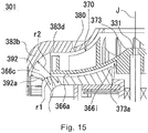
- Fig. 15 is an enlarged cross-sectional view of an air blowing device 301 according to an exemplary fourth embodiment of the present invention.
- Components of the air blowing device 301 according to the fourth embodiment that are the same as those of the above-described air blowing device 1, air blowing device 101, or air blowing device 201 may be denoted by the same reference symbols, and description thereof may be omitted.
- an outer face of a ring-shaped cover outer edge portion 366c is a curved face that bulges toward the outer side in the radial direction and the upper side in the axial direction, at a region where the gap is a first width 392a.
- An inner face of an exhaust air guide portion 383 has a guide-portion inner-side recessed portion 383b that is recessed toward the outer side in the radial direction and the upper side in the axial direction. Unlike the air blowing device 201, in the air blowing device 301 the exhaust air guide portion 383 has no guide-portion inner-side protruding portion.
- a curvature radius r1 of the outer face of a ring-shaped cover outer edge portion is smaller than a curvature radius r2 of the inner face of the exhaust air guide portion. That is to say, the inner face of the exhaust air guide portion 383 curves more gradually as compared to the outer face of the ring-shaped cover outer edge portion 366c. Accordingly, fluid flowing through a flow path 392 is smoothly guided toward the outer side in the radial direction and the lower side in the axial direction. The gap becomes a first width 392a at a partial region within the flow path 392. Accordingly, the static pressure of the fluid can be increased at a partial region within the flow path 392 while smoothing the flow of the fluid.
- the position in the radial direction of a radial-direction inner edge 366g of the ring-shaped cover outer edge portion and the position in the radial direction of a radial-direction inner edge 383d on the inner face of the exhaust air guide portion are the same. That is to say, the boundary region of a ring-shaped cover upper face portion 366a and the ring-shaped cover outer edge portion 366c, and a radial-direction inner edge 383d on the inner face of the exhaust air guide portion face each other in the axial direction.
- the flow path 392 that has a smooth curvature can be configrued at the outer edge of the impeller 370, from the ring-shaped cover outer edge portion 366c and exhaust air guide portion 383.
- the air-blowing efficiency of the air blowing device 301 can be improved even further.
- the position in the radial direction of the radial-direction inner edge 366g of the ring-shaped cover outer edge portion and the position in the radial direction of the outer edge of the impeller 370 in the radial direction are the same.
- a position at the radial-direction outer side of the ring-shaped cover upper face portion 366a where a generally planar region changes to a smooth curved face can be taken as the radial-direction inner edge 366g of the ring-shaped cover outer edge portion.
- a position of the inner face of the impeller housing 380 in a region near the radial-direction outer side of the impeller 370 where a generally planar region changes to a smooth curved face can be taken as the radial-direction inner edge 366g of the ring-shaped cover outer edge portion.
- the lower face of the base portion 373 has a base-portion recessed portion 373a that is recessed toward the upper side in the axial direction.
- the ring-shaped cover upper face portion 366a has an inner-side protruding portion 366i.
- the inner-side protruding portion 366i protrudes further toward the upper side in the axial direction than the lower end of the base portion lower face, at a position further toward the inner side in the radial direction than the radial-direction outer edge of the impeller 370.
- the inner-side protruding portion 366i faces at least part of the base-portion recessed portion 373a across a gap in the axial direction.
- fluid that has been discharged from the impeller 370 can be suppressed from flowing in between the ring-shaped cover upper face portion 366a and an inner-side protruding portion 366, while forming the base-portion recessed portion 373a at the base portion 373.
- Fig. 16 is a perspective view of a vacuum cleaner 100.
- the air blowing devices 1, 101, 201, and 301 according to exemplary embodiments of the present invention are installed in the vacuum cleaner 100, for example. Accordingly, the air blowing efficiency of the vacuum cleaner 100 is improved. Note that the air blowing devices 1, 101, 201, and 301 can be installed in other electric devices besides the vacuum cleaner 100 as well.
- the air blowing device according to the present invention is applicable to vacuum cleaners and so forth, for example.
Abstract
Description
- The present invention relates to an air blowing device. The air blowing device is installed in a vacuum cleaner, for example.
- Static pressure is required of an air blowing device installed in a vacuum cleaner. An example of such an air blowing device is that disclosed in Japanese Unexamined Patent Application Publication No.
2011-80427 2011-80427 - PTL 1: Japanese Unexamined Patent Application Publication No.
2011-80427 - Air discharged from an impeller is discharged from the outer side of the impeller via multiple bent portions provided to a flow path connected within a bracket in the air blowing device described in Japanese Unexamined Patent Application Publication No.
2011-80427 - It is an object of the present invention to improve blowing efficiency in an air blowing device even in a case where the flow path is short.
- An air blowing device according to an exemplary embodiment of the present invention includes a motor having a shaft that is disposed following a central axis extending in a vertical direction, a ring-shaped cover that is disposed further to an upper side in an axial direction than the motor, an impeller fixed to the shaft, and an impeller housing that encompasses above the impeller and the outer side thereof in the radial direction. The impeller includes a base portion that spreads in a direction orthogonal to the shaft, and a plurality of moving blades that are connected to the base portion and arrayed in a peripheral direction. The impeller housing includes an exhaust air guide portion that extends toward an outer side in the radial direction and toward a lower side, at a side further outward from an outer edge of the impeller in the radial direction. The ring-shaped cover includes a ring-shaped cover upper face portion that spreads in a direction orthogonal to the shaft, and faces the base portion in the axial direction, a ring-shaped cover outer edge portion that is positioned further on the outer side from the outer edge of the impeller in the radial direction. An outer face of the ring-shaped cover outer edge portion and an inner face of the exhaust air guide portion are disposed across a gap, and the gap configures a flow path through which a fluid flowing in from the impeller is guided. The gap has a first width where a distance between the outer face of the ring-shaped cover outer edge portion and the inner face of the exhaust air guide portion is shortest, in a region further to the outer side from the radial-direction inner edge of the ring-shaped cover outer edge portion and further to the inner side from the radial-direction outer edge of the ring-shaped cover outer edge portion. The first width is smaller than a flow-in opening width where the fluid flows into the gap and a flow-out opening width where the fluid flows out from the gap, which are the gap.
- According to the air blowing device in an exemplary embodiment of the present invention, efficiency of the air blowing device can be improved. Also, a vacuum cleaner having such an air blowing device can be provided.
-
- [
Fig. 1] Fig. 1 is a cross-sectional view of an air blowing device according to an embodiment. - [
Fig. 2] Fig. 2 is a disassembled perspective view of the air blowing device according to the embodiment. - [
Fig. 3] Fig. 3 is a perspective view of a motor according to the embodiment, as viewed from the lower side. - [
Fig. 4] Fig. 4 is a perspective view of a stator according to the embodiment. - [
Fig. 5] Fig. 5 is a disassembled perspective view illustrating a stator, a circuit board, and a lower lid. - [
Fig. 6] Fig. 6 is a plane cross-sectional view of the motor. - [
Fig. 7] Fig. 7 is an explanatory diagram illustrating a mounted form of a rotation sensor, and is a perspective view of a stator vane member as viewed from below. - [
Fig. 8] Fig. 8 is a cross-sectional view where a part of the impeller, stator vane member, and impeller housing are illustrated enlarged. - [
Fig. 9] Fig. 9 is a partial side view of a stator vane member. - [
Fig. 10] Fig. 10 is a side view of a stator vane member. - [
Fig. 11] Fig. 11 is a plan view of moving blades of the impeller. - [
Fig. 12] Fig. 12 is a longitudinal-section view of an air blowing device according to a second embodiment. - [
Fig. 13] Fig. 13 is a longitudinal-section view of an air blowing device according to a third embodiment. - [
Fig. 14] Fig. 14 is a bottom view of an impeller according to the third embodiment. - [
Fig. 15] Fig. 15 is an enlarged longitudinal-section view of an air blowing device according to a fourth embodiment. - [
Fig. 16] Fig. 16 is a perspective view of a vacuum cleaner. - A motor according to an embodiment of the present invention will be described below with reference to the drawings. It should be noted that the scope of the present invention is not restricted by the following embodiments, and that modifications may be optionally made within the scope of the technical idea of the present invention. Further, in the following drawings, the scale and number and so forth of the structures may differ from that of the actual structures, in order to facilitate understanding of the configurations.
- In the drawings, an XYZ coordinate system will be illustrated as a three-dimensional orthogonal coordinate system as appropriate. In the XYZ coordinate system, a Z-axis direction is a direction parallel to an axial direction along a central axis J illustrated in
Fig. 1 . An X-axis direction is a direction orthogonal to the Z-axis direction and is a right-left direction inFig. 1 . A Y-axis direction is a direction that is orthogonal to both of the X-axis direction and the Z-axis direction. - Also, in the following description, a direction (the Z-axis direction) in which the central axis J extends will be referred to as a vertical direction. The positive side in the Z-axis direction (+Z side) will be referred to as the "upper side (upper side in the axial direction)" and the negative side in the Z-axis direction (-Z side) will be referred to as the "lower side (lower side in the axial direction)". Note that the vertical direction, the upper side, and the lower side are terms that are used simply for the purpose of description and do not limit the actual positional relationship or direction. In addition, unless otherwise specifically noted, a direction (the Z-axis direction) parallel to the central axis J will be simply referred to as an "axial direction", a radial direction of which the central axis J is the center will be simply referred to as a "radial direction", and a circumferential direction around the central axis J will be simply referred to as a "circumferential direction".
-
Fig. 1 is a cross-sectional view of an air blowing device according to the present embodiment.Fig. 2 is a disassembled perspective view of the air blowing device according to the present embodiment. - An air blowing device 1 has a
motor 10, animpeller 70, astator vane member 60, and animpeller housing 80, as illustrated inFig. 1 andFig. 2 . - The
stator vane member 60 is attached to the upper side (+Z side) of themotor 10. Theimpeller housing 80 is attached to the upper side of thestator vane member 60. Theimpeller 70 is accommodated between thestator vane member 60 and theimpeller housing 80. Theimpeller 70 is attached to themotor 10 rotatably on the central axis J. -
Fig. 3 is a perspective view of the motor according to the embodiment, as viewed from the lower side. - The
motor 10 has ahousing 20, alower lid 22, arotor 30 that has ashaft 31, astator 40, acircuit board 50, a lower-side bearing 52a, and an upper-side bearing 52b, as illustrated inFig. 1 . - The
housing 20 is a covered cylindrical container that accommodates therotor 30 andstator 40. Thehousing 20 has a cylindricalperipheral wall 21, anupper lid portion 23 situated at the upper end of theperipheral wall 21, and an upper-sidebearing holding portion 27 situated at the middle of theupper lid portion 23. Thestator 40 is fixed on the inner side face of thehousing 20. The upper-sidebearing holding portion 27 is cylindrical in form and protrudes upwards from the middle of theupper lid portion 23. The upper-sidebearing holding portion 27 holds the upper-side bearing 52b therein. - Housing-upper-portion through
holes housing 20 in the radial direction are provided at the upper portion side of the peripheral wall of thehousing 20, as illustrated inFig. 1 andFig. 3 . Three housing-upper-portion throughholes 25 and three housing-upper-portion throughholes 26 are provided in the peripheral wall of thehousing 20 in an alternating manner around the axis (seeFig. 6 ). According to this configuration, part of air discharged from later-describedvents 95 flows into thehousing 20, whereby astator core 41 andcoil 42 can be cooled. A steppedportion 28 encompassing theupper lid portion 23 around the axis is provided between theperipheral wall 21 andupper lid portion 23 of thehousing 20. - The
lower lid 22 is attached to a lower-side (-Z side) opening of thehousing 20. A cylindrical lower-sidebearing holding portion 22c that protrudes toward the lower side from the lower face of thelower lid 22 is provided at the middle of thelower lid 22. The lower-sidebearing holding portion 22c holds the lower-side bearing 52a. - Arc-shaped through
holes 22a, having a width in the radial direction, are provided to thelower lid 22 at three locations around the axis, as illustrated inFig. 3 . Notchedportions 22b where the outer peripheral portion of thelower lid 22 has been linearly notched are provided at three positions on the outer peripheral edge of thelower lid 22. Gaps between the openingend 20a at the lower side of thehousing 20 and the notchedportions 22b are lower-side openings 24 of themotor 10. - The
rotor 30 has theshaft 31, arotor magnet 33, a lower-sidemagnet fixing member 32, and an upper-sidemagnet fixing member 34, as illustrated inFig. 1 . Therotor magnet 33 has a cylindrical shape, and encompasses theshaft 31 around the axis (θz direction) at the outer side in the radial direction. The lower-sidemagnet fixing member 32 and upper-sidemagnet fixing member 34 are cylindrical shapes, having a diameter equivalent to that of therotor magnet 33. The lower-sidemagnet fixing member 32 and upper-sidemagnet fixing member 34 are attached to theshaft 31, sandwiching therotor magnet 33 from both sides in the axial direction. The upper-sidemagnet fixing member 34 has a small radius portion 34a at the upper side portion in the central axis direction, of which diameter is smaller than the lower side (rotor magnet 33 side). - The
shaft 31 is rotatably supported around the axis (θz direction) by the lower-side bearing 52a and upper-side bearing 52b. Theimpeller 70 is attached to the end of theshaft 31 at the upper side (+Z side). Theimpeller 70 integrally rotates with theshaft 31 on the axis. -
Fig. 4 is a perspective view of thestator 40 according to the present embodiment.Fig. 5 is a disassembled perspective view illustrating thestator 40,circuit board 50, andlower lid 22.Fig. 6 is a plane cross-sectional view of themotor 10. - The
stator 40 is positioned on the outer side from therotor 30 in the radial direction. Thestator 40 encompasses therotor 30 around the axis (θz direction). Thestator 40 has astator core 41, multiple (three) upper-side insulators 43, multiple (three) lower-side insulators 44, and coils 42, as illustrated inFig. 4 andFig. 5 . - The
stator core 41 includes a core backportion 41a and multiple (three)teeth portions 41b, as illustrated inFig. 5 . The core backportion 41a is ring-shaped around the center axis. The core backportion 41a has a configuration wherelinear portions 41c at three positions around the axis, and threearc portions 41d, are alternatingly positioned. Theteeth portions 41b each extend inward in the radial direction from the inner peripheral face of thelinear portions 41c. Theteeth portions 41b are disposed equidistantly in the circumferential direction. Aninclined member 46 that guides exhaust air into thestator 40 is disposed above eacharc portion 41d of the core backportion 41a. Theinclined members 46 have a shape where the thickness progressively becomes smaller from the outer side in the radial direction toward the inner side. - The upper-
side insulators 43 are insulating members covering part of the upper face and side faces of thestator core 41. The upper-side insulators 43 are provided corresponding to each of the threeteeth portions 41b. The upper-side insulators 43 each have an upper-side outerperipheral wall portion 43a that is positioned at the upper side of the core backportion 41a, an upper-side innerperipheral wall portion 43e that is positioned at the upper side of the tip of theteeth portion 41b, and an upper-side insulating portion 43d that links the upper-side outerperipheral wall portion 43a and upper-side innerperipheral wall portion 43e in the radial direction, and is positioned at the upper side of a portion of theteeth portion 41b where the coil is wound. - The lower-
side insulators 44 are insulating members covering part of the lower face and side faces of thestator core 41. The lower-side insulators 44 are provided corresponding to each of the threeteeth portions 41b. The lower-side insulators 44 each have a lower-side outerperipheral wall portion 44a that is positioned at the lower side of the core backportion 41a, a lower-side innerperipheral wall portion 44c that is positioned at the lower side of the tip of theteeth portion 41b, and a lower-side insulating portion 44b that links the lower-side outerperipheral wall portion 44a and lower-side innerperipheral wall portion 44c in the radial direction, and is positioned at the lower side of a portion of theteeth portion 41b where the coil is wound. - The upper-
side insulators 43 and lower-side insulators 44 are disposed sandwiching theteeth portions 41b of thestator core 41 in the vertical direction. Thecoils 42 are wound on theteeth portions 41b covered by the upper-side insulating portions 43d of the upper-side insulators 43 and the lower-side insulating portions 44b of the lower-side insulators 44. - The three upper-side outer
peripheral wall portions 43a positioned above the core backportion 41a of thestator core 41 encompass thecoils 42, at the upper side of thestator core 41. The upper-side outerperipheral wall portions 43a each have a firstside end face 43b and a secondside end face 43c at both ends in the peripheral direction. The first side end faces 43b are inclined faces inclined in the radial direction and facing outwards in the radial direction. The second side end faces 43c are inclined faces inclined in the radial direction and facing inwards in the radial direction. Of the outer peripheral faces of the upper-side outerperipheral wall portions 43a, portions situated above thelinear portions 41c are upper-side flat faces 43f extending in the axial direction matching the outer peripheral face of the linear portions. Arc-shaped faces disposed following the inner peripheral face of thehousing 20 are disposed on both sides of the upper-side flat faces 43f in the peripheral direction. - The upper-side outer
peripheral wall portions 43a that are adjacent in the circumferential direction are separated from each other by predetermined gaps, as illustrated inFig. 6 . Among adjacent upper-side outerperipheral wall portions 43a, the firstside end face 43b of one upper-side outerperipheral wall portion 43a and the secondside end face 43c of the other upper-side outerperipheral wall portion 43a face each other in the circumferential direction. The degree of inclination of the firstside end face 43b in the radial direction and the degree of inclination of the secondside end face 43c in the radial direction differ. More specifically, the width of openingportions 90 at the outer side in the radial direction from gaps CL formed between adjacent upper-side outerperipheral wall portions 43a in the peripheral direction is narrower than the width in the peripheral direction of openingportions 91 at the inner side in the radial direction. - Below the gaps CL are situated the
inclined members 46 disposed above the core backportion 41a. Theinclined members 46 are sandwiched between the first side end faces 43b and second side end faces 43c. The gaps CL are situated on the inner side of the housing-upper-portion throughholes 26 of thehousing 20. The housing-upper-portion throughholes 26 and the gaps CL make up airflow paths guiding exhaust air flowing in from the outer side of thehousing 20 to the inner side of thestator 40. The direction of inclination of the gaps CL in the radial direction as viewed from above (the direction from the outer side in the radial direction toward the inner side) matches the direction of flow of exhaust air discharged from thestator vane member 60 in the peripheral direction. That is to say, this matches the direction of rotation of theimpeller 70. - The opening
portions 90 at the inlet side of the gaps CL are formed relatively large, so a greater amount of exhaust air can be suctioned in from the housing-upper-portion throughholes 26, while the widths of the openingportions 91 are relatively narrow, so air discharged from the gaps CL can be caused to flow to the intended positions (coils 42) more accurately, as illustrated inFig. 6 . Accordingly, thestator core 41 and coils 42 can be cooled more efficiently by the air flowing in from the housing-upper-portion through holes 26. - The three lower-side outer
peripheral wall portions 44a positioned at the lower side from the core backportion 41a encompass thecoils 42 at the lower side of thestator core 41. Although there are gaps between lower-side outerperipheral wall portions 44a that are adjacent in the circumferential direction, the lower-side outerperipheral wall portions 44a may be in contact with each other in the circumferential direction. Of the outer peripheral faces of the lower-side outerperipheral wall portions 44a, the portions positioned at the lower side from thelinear portions 41c of the core backportion 41a are lower-side flat faces 44d extending in the axial direction matching the outer peripheral face of thelinear portions 41c. At both sides in the peripheral direction of the lower-side flat faces 44d, arc-shaped faces are provided having been disposed following the inner peripheral face of thehousing 20. - Multiple (three in the illustration)
plate portions 45 that extend in the axial direction are provided to the lower-side flat faces 44d. Theplate portions 45 are erected approximately perpendicular to the lower-side flat faces 44d, as illustrated inFig. 6 . The tips of theplate portions 45 at the outer side in the radial direction reach the inner peripheral face of thehousing 20. Theplate portions 45 section the region between the lower-side outerperipheral wall portion 44a and thehousing 20 into multiple regions in the circumferential direction. - The
circuit board 50 is disposed between thestator 40 and thelower lid 22, as illustrated inFig. 1 andFig. 6 . Thecircuit board 50 has a circular ring-shapedmain unit portion 50a, and three protrudingportions 50b that protrude toward the outer side from the outer edge of themain unit portion 50a, in a direction inclined as to the radial direction. Themain unit portion 50a has a hole through which theshaft 31 is passed. Thecircuit board 50 is fixed to the lower-side insulators 44. - The
circuit board 50 has at least threerotary sensors 51 mounted thereupon, as illustrated inFig. 6 . Therotary sensors 51 are Hall effect sensors, for example. Thecircuit board 50 may be electrically connected to thecoils 42. In this case, a driving circuit that outputs driving signals to thecoils 42 may be mounted on thecircuit board 50. -
Fig. 7 is an explanatory diagram illustrating a mounting state of arotary sensor 51. - The
rotary sensors 51 are disposed interposed between tip portions of lower-side innerperipheral wall portions 44c that are adjacent in the circumferential direction, as illustrated inFig. 6 andFig. 7 . The threerotary sensors 51 are equidistantly disposed every 120° in the circumferential direction. The faces of therotary sensors 51 on the inner side in the radial direction face therotor magnet 33. Therotor magnet 33 is disposed at the center portion of therotor 30 in the axial direction in the case of the present embodiment. Accordingly, therotary sensors 51 are connected to thecircuit board 50 byleads 51a of a length corresponding to the length from thecircuit board 50 to therotor magnet 33 in the axial direction. The length of themotor 10 in the axial direction can be reduced by threerotary sensors 51 being disposed interposed between the tip portions of lower-side innerperipheral wall portions 44c that are adjacent in the circumferential direction, as compared to a structure where sensor magnets are disposed below the lower-sidemagnet fixing member 32 and therotary sensors 51 are disposed further below the sensor magnets, for example. - A mechanism that supports the
rotary sensors 51 may be provided to the tip portion of the lower-side innerperipheral wall portions 44c. For example, recesses may be provided into which therotary sensors 51 are inserted, thereby suppressing movement of therotary sensors 51 in the radial direction. Alternatively, therotary sensors 51 may be fixed to the lower-side innerperipheral wall portions 44c by snap-fitting or the like. - The
lower lid 22 is attached to the openingend 20a of thehousing 20 accommodating thestator 40 andcircuit board 50. At least part of the three throughholes 22a of thelower lid 22 are situated further on the outer side in the radial direction than the outer peripheral edge of themain unit portion 50a of thecircuit board 50. - The notched
portions 22b at the outer periphery of thelower lid 22 are disposed approximately matching thelinear portions 41c of thestator core 41, the upper-side flat faces 43f of the upper-side insulators 43, and the lower-side flat faces 44d of the lower-side insulators 44, as viewed in the axial direction. The lower-side openings 24 at the lower face of themotor 10 serve as vents of the air flow paths FP between thestator 40 andhousing 20. - Next, the
stator vane member 60,impeller 70, andimpeller housing 80 will be described. -
Fig. 7 is a perspective view of thestator vane member 60 as viewed from below.Fig. 8 is a cross-sectional view where a part of theimpeller 70,stator vane member 60, andimpeller housing 80 are illustrated enlarged.Fig. 9 is a partial side view of thestator vane member 60. - The
stator vane member 60 has a firststator vane member 61a, and a ring-shapedcover portion 61b, as illustrated inFig. 1 andFig. 2 . The firststator vane member 61a and ring-shapedcover portion 61b are attached to the upper face of themotor 10, having been layered in the axial direction. - The first
stator vane member 61a has a lower-portion statorvane supporting ring 62, anattachment ring 63, three linkingportions 64, and multiple lower-portion stator vanes 67b. The lower-portion statorvane supporting ring 62 andattachment ring 63 are disposed coaxially, and are linked by the three linkingportions 64 extending in the radial direction. The three linkingportions 64 are disposed at equidistant intervals of 120° each in the peripheral direction. The linkingportions 64 have throughholes 64a that pass through in the axial direction. Three throughholes 64a are disposed at equidistant intervals of 120° each in the peripheral direction. Theattachment ring 63 has a recessedgroove 63a on the upper face thereof, that is concentric with theattachment ring 63. - The multiple lower-
portion stator vanes 67b protrude toward the outer side in the radial direction from the outer peripheral face of the lower-portion statorvane supporting ring 62. The multiple lower-portion stator vanes 67b are disposed equidistantly in the peripheral direction. The outer peripheral face of the lower-portion statorvane supporting ring 62 is a tapered form that tapers toward the upper side. The lower-portion stator vanes 67b have shapes that increase in width in the radial direction the further toward the upper side. - The ring-shaped
cover portion 61b has a disc-ring shaped ring-shaped coverflat face portion 66a, a cylindrical upper-portion statorvane supporting ring 66b extending to the lower side from the outer peripheral edge of the ring-shaped-coverflat face portion 66a, multiple upper-portion stator vanes 67a, anouter perimeter ring 65 connected to the outer side of the upper-portion stator vanes 67a ion the radial direction, and a ring-shaped protrudingportion 66c that protrudes upward from the outer peripheral edge of the ring-shaped coverflat face portion 66a. The multiple upper-portion stator vanes 67a link the outer peripheral face of the upper-portion statorvane supporting ring 66b and the inner peripheral face of theouter perimeter ring 65. The upper-portion statorvane supporting ring 66b has a steppedportion 66d that extends the full circumference of the outer peripheral side of the lower end portion thereof. - The ring-shaped cover
flat face portion 66a has anattachment ring 68 that extends downwards from the lower face at the middle portion, and threecolumnar protruding portions 69 that protrude downwards from the lower face of the ring-shaped-coverflat face portion 66a, as illustrated inFig. 8 . Theattachment ring 68 has acylindrical cylinder portion 68a, and a ring-shaped protrudingportion 68b that protrudes downwards from the outer peripheral portion in the radial direction of the lower end face of thecylinder portion 68a. The threecolumnar protruding portions 69 have the same diameters and heights, and are equidistantly disposed every 120° in the circumferential direction. Thecolumnar protruding portions 69 are hollow in the present embodiment, and each have a throughhole 69b at the middle of anend face 69a at the lower side that passes through in the axial direction. - The upper-side
bearing holding portion 27 of themotor 10 is inserted into theattachment ring 63 of the firststator vane member 61a, as illustrated inFig. 1 andFig. 9 . The lower end face of the lower-portion statorvane supporting ring 62 of the firststator vane member 61a comes into contact with a steppedface 28a facing upwards on the steppedportion 28 of themotor 10. - The ring-shaped
cover portion 61b is attached to the firststator vane member 61a. The upper-sidebearing holding portion 27 is inserted into theattachment ring 68 of the ring-shapedcover portion 61b, as illustrated inFig. 9 . The protrudingportion 68b at the lower side tip of theattachment ring 68 is fit into the recessedgroove 63a of the firststator vane member 61a. The steppedportion 66d of the upper-portion statorvane supporting ring 66b of the ring-shapedcover portion 61b is fit to an upper side opening end of the lower-portion statorvane supporting ring 62. The outer peripheral face of the upper-portion statorvane supporting ring 66b and the outer peripheral face of the lower-portion statorvane supporting ring 62 are smoothly connected in the vertical direction. - The
columnar protruding portions 69 of the ring-shapedcover portion 61b are inserted into the throughholes 64a of the firststator vane member 61a. The end faces 69a of the columnar protrudingportions 69 come into contact with the upper face of theupper lid portion 23 of themotor 10. The ring-shapedcover portion 61b and themotor 10 are fastened to each other, by bolts BT inserted through the throughholes 69b of the columnar protrudingportions 69 andscrew holes 23a of theupper lid portion 23. The firststator vane member 61a is positioned in the peripheral direction by thecolumnar protruding portions 69 of the ring-shapedcover portion 61b, and is fixed to themotor 10 by being pressed by theattachment ring 68 and upper-portion statorvane supporting ring 66b of the ring-shapedcover portion 61b. - The stator vane member 61 is configured of two members (first
stator vane member 61a and ring-shapedcover portion 61b), while only the ring-shapedcover portion 61b is fastened to themetal housing 20 of themotor 10 in the present embodiment. This fixing arrangement enables trouble to be suppressed from occurring in the state of fastening between themotor 10 andstator vane member 60 when change in temperature of the air blowing device 1 occurs. - Specifically, in an assumed case where both of the first
stator vane member 61a and ring-shapedcover portion 61b are fixed to themotor 10 by common bolts BT being passed through, the bolts BT fasten down the two resin members, and the amount of change in volume due to temperature change increases. Accordingly, there is concern that thestator vane member 60 will shrink in low-temperature environments, creating looseness. In comparison with this, in the present embodiment, the end faces 69a of the columnar protrudingportions 69 of the ring-shapedcover portion 61b are brought into contact with thehousing 20 and fastened by the bolts BT, so the thickens of the resin member fastened by the bolts BT can be reduced. Accordingly, the amount of change in volume when temperature changes is smaller, thereby enabling loosening of the fastening to be suppressed. -
Fig. 10 is a side view of thestator vane member 60. - The same number of upper-
portion stator vanes 67a and lower-portion stator vanes 67b are arrayed in the peripheral direction, as illustrated inFig. 10 . The upper-portion stator vanes 67a and lower-portion stator vanes 67b correspond one on one, and are disposed arrayed in the axial direction. In the case of the present embodiment, the angle of inclination as to the axial direction of the upper-portion stator vanes 67a is greater than the angle of inclination as to the axial direction of the lower-portion stator vanes 67b. The upper-portion stator vanes 67a are disposed inclined at a relatively great angle, in order to cause exhaust air that flows in a direction inclined to the rotation direction of theimpeller 70 to efficiently flow in between the upper-portion stator vanes 67a. The lower-portion stator vanes 67b guide the exhaust air downwards, so that exhaust air discharged from thevents 95 does not flow outwards in the radial direction. - A gap 67c is a gap that extends in the horizontal direction in the present embodiment, but may be a gap that extends in an oblique direction as to the horizontal direction. In a case of a gap extending in an oblique direction, the direction preferably is the same as the direction of inclination of the upper-
portion stator vanes 67a. Providing such an oblique-direction gap results in exhaust air passing through the gap, and an entire exhaustair flow path 93 can be effectively used. - The exhaust
air flow path 93 shifts toward the outer side in the radial direction near thevents 95 in the present embodiment, as illustrated inFig. 9 . That is to say, the outer peripheral face of the lower-portion statorvane supporting ring 62 of the firststator vane member 61a is tapered in shape, with the diameter increasing toward the lower side. Of theouter perimeter ring 65 of the ring-shapedcover portion 61b, alower ring 65b facing toward the lower-portion statorvane supporting ring 62 in the radial direction has a skirt-like shape where the inner circumference diameter increases toward the lower side. The exhaustair flow path 93 spreads more to the outer side in the radial direction the lower the position is, with the width in the radial direction unchanged. Thus, the horizontal cross-sectional area of the exhaustair flow path 93 gradually increases the closer to thevents 95. This enables exhaust noise at the time of air being discharged from thevents 95 to be reduced. - The
impeller 70 discharges fluid suctioned from anintake port 70a that is opened toward the upper side, toward the outer side in the radial direction via internal flow paths. Theimpeller 70 has an impellermain body 71 and animpeller hub 72. - The impeller
main body 71 has abase portion 73, multiple movingblades 74, and ashroud 75. Thebase portion 73 is disc-shaped, and has a throughhole 73a passing through in the axial direction at the middle portion. The perimeter of the throughhole 73a of thebase portion 73 is aninclined portion 73b that has a conical face shape extending at the upper side. The movingblades 74 are plate-shaped members curved in the circumferential direction, that extend from the inner side in the radial direction toward the outer side on the upper face of thebase portion 73. The movingblades 74 are disposed erected following the axial direction. Theshroud 75 is a cylindrical shape that tapers toward the upper side in the axial direction. An opening portion at the middle of theshroud 75 is theintake port 70a of theimpeller 70. Thebase portion 73 andshroud 75 are linked by the movingblades 74. -
Fig. 11 is a plan view of the movingblades 74 of theimpeller 70. - The multiple moving
blades 74 are disposed following the circumferential direction (θZ direction) on the upper face of thebase portion 73, as illustrated inFig. 11 . The movingblades 74 are erected perpendicularly from the upper face of thebase portion 73 following the axial direction, as illustrated inFig. 1 . - In the present embodiment, three types of moving
blades 74 are disposed, with the same types of moving blades being equidistantly disposed in the circumferential direction. The multiple movingblades 74 in the present embodiment include multiple (three) first movingblades 74a, multiple (three) second movingblades 74b, and multiple (six) third movingblades 74c. The three first movingblades 74a are disposed at equidistantly every 120° in the circumferential direction. The second movingblades 74b are each disposed at intermediate positions between first movingblades 74a adjacent in the circumferential direction. The three second movingblades 74b are also disposed equidistantly every 120° in the circumferential direction. The third movingblades 74c are each disposed at intermediate positions between first movingblades 74a and second movingblades 74b adjacent in the circumferential direction. The six third movingblades 74c are disposed equidistantly every 60° in the circumferential direction. - The moving
blades 74 extend on the upper face of thebase portion 73 having a curvature in plan view (XY plane view). One end of each movingblade 74 is positioned on an outer peripheral edge of thebase portion 73. The other end of each movingblade 74 is positioned further on the inner side than the outer peripheral edge of thebase portion 73 in the radial direction. - That is to say, the end portions of each of the first moving
blades 74a, the second movingblades 74b, and the third movingblades 74c, at the outer side in the radial direction, are all positioned on the outer edge of thebase portion 73. On the other hand, end portions P1 of the first movingblades 74a on the inner peripheral side are positioned closest to the center of thebase portion 73. End portions P2 of the second movingblades 74b on the inner peripheral side are positioned on the outer side in the radial direction from the end portions P1 of the first movingblades 74a. End portions P3 of the third movingblades 74c on the inner peripheral side are positioned further on the outer side in the radial direction from the end portions P2 of the second movingblades 74b. This configuration enables turbulence within theimpeller 70 to be reduced, so the air blowing efficiency of theimpeller 70 is improved. - The first moving
blades 74a, the second movingblades 74b, and the third movingblades 74c, each have a shape that is curved like a bow in a counterclockwise direction. - The first moving
blades 74a are each formed of four arcs that are different in radius of curvature. A projectingblade face 74d of the first movingblades 74a has three inflection points CP11, CP12, and CP13, in the longitudinal direction. - The second moving
blades 74b are each formed of three arcs that are different in radius of curvature. A projecting blade face 74e of the second movingblades 74b has two inflection points CP21 and CP22 in the longitudinal direction. - The third moving
blades 74c are each formed of two arcs that are different in radius of curvature. A projectingblade face 74f of the third movingblades 74c has one inflection point CP31 in the longitudinal direction. - In the present embodiment, the inflection point CP11 of each first moving
blade 74a, the inflection point CP21 of each second movingblade 74b, and the inflection point CP31 of each third movingblade 74c, are each disposed at the same radius position C1 on thebase portion 73. Further, the radius of curvature of a portion of each first movingblade 74a that is further on the outer side of the radial position C1, the radius of curvature of a portion of each second movingblade 74b that is further on the outer side of the radial position C1, and the radius of curvature of a portion of each third movingblade 74c that is further on the outer side of the radial position C1, are the same as each other. - Next, the inflection point CP12 of each first moving
blade 74a, the inflection point CP22 of each second movingblade 74b, and the end portion P3 of each third movingblade 74c are each disposed at the same radius position C2 on thebase portion 73. Further, the radius of curvature of a portion of each first movingblade 74a between the radial positions C1 and C2, the radius of curvature of a portion of each second movingblade 74b between the radial positions C1 and C2, and the radius of curvature of a portion of each third movingblade 74c between the radial positions C1 and C2, are the same as each other. - Next, the inflection point CP13 of each first moving
blade 74a and the end portion P2 of each second movingblade 74b are disposed at the same radius position C3 on thebase portion 73. Further, the radius of curvature of a portion of each first movingblade 74a between the radial positions C2 and C3 and the radius of curvature of a portion of each second movingblade 74b between the radial positions C2 and C3 are the same as each other. - The radii of curvature of the blade faces 74d to 74f of the moving blades 74 (74a through 74c) in the present embodiment are different for each region of the
impeller 70 in the radial direction. Meanwhile, portions of different types of moving blades 74 (the first movingblades 74a through third movingblades 74c) that belong to the same region in the radial direction are set to have the same radius of curvature. - In the present embodiment, the radial position C3 agrees with the
intake port 80a of theimpeller housing 80 as seen in the axial direction. Accordingly, only the portions of the first movingblades 74a further on the inner peripheral side than the inflection point CP13 are disposed inward of theintake port 80a. - The
impeller hub 72 includes acylindrical portion 72a that extends in the axial direction, a disc-shapedflange portion 72b that extends outwards in the radial direction from the lower portion of the outer peripheral face of thecylindrical portion 72a, and multiple projectingportions 72c that protrude upwards from the upper face of theflange portion 72b. Thecylindrical portion 72a includes a taperedinclined face portion 72d that becomes tapered toward the tip portion at the upper side. - The
impeller hub 72 is attached to the impellermain body 71 by inserting thecylindrical portion 72a into the throughhole 73a of thebase portion 73 from the lower side. Thecylindrical portion 72a may be press-fitted into the throughhole 73a, or may be fixed using an adhesive agent or the like. Theflange portion 72b of theimpeller hub 72 supports the impellermain body 71 from the lower side. The projectingportions 72c on theflange portion 72b are fitted intorecesses 73c on the lower face of thebase portion 73. Fitting the projectingportions 72c into therecesses 73c restricts relative movement of the impellermain body 71 and theimpeller hub 72 in the circumferential direction. - Due to the
impeller hub 72 including theflange portion 72b, theflange portion 72b can support the impellermain body 71 over a wide area in the radial direction from below. Accordingly, theimpeller 70 can be held in a stable manner, and stability at the time of high-speed rotation is raised. That is to say, theflange portion 72b can support the impellermain body 71 over a wide area in the radial direction from below, so deviation as to theshaft 31 of theimpeller 70 can be reduced. - The
inclined face portion 72d at the tip of thecylindrical portion 72a of theimpeller hub 72 and theinclined face portion 73b of thebase portion 73 are smoothly connected to each other in the vertical direction in theimpeller 70. Theinclined face portion 72d and theinclined face portion 73b make up a ring-shaped inclined face 70b that guides fluid suctioned from theintake port 70a of theimpeller 70 to the outer side in the radial direction. - Configuring the ring-shaped inclined face 70b from the impeller
main body 71 and theimpeller hub 72 enables the maximum height of the ring-shaped inclined face 70b to be increased by increasing the length of thecylindrical portion 72a (inclined face portion 72d) without increasing the height of theinclined face portion 73b of thebase portion 73. Accordingly, a ring-shaped inclined face 70b having a preferable shape can be realized while suppressing increase in thickness of thebase portion 73. - The
impeller hub 72 is preferably made of metal. In this case, theshaft 31 and theimpeller 70 can be strongly linked to each other. Accordingly, theimpeller 70 can be rotated at high speeds in a stable manner. Moreover, a metal face can be used as theinclined face portion 72d, and accordingly the surface of the upper tip of the ring-shaped inclined face 70b can be smoothed. - The
impeller 70 is fixed to theshaft 31 by fitting the upper end portion of theshaft 31 into thecylindrical portion 72a of theimpeller hub 72 from the lower side. As illustrated inFig. 1 andFig. 9 , theimpeller 70 connected to theshaft 31 is disposed at the inner side of the ring-shaped protrudingportion 66c of the ring-shapedcover portion 61b. Accordingly, the protrudingportion 66c is disposed nearby avent 70c of theimpeller 70. - The protruding
portion 66c guides exhaust air discharged from theimpeller 70 to the lower side, along with a later-describedexhaust air guide 83 of theimpeller housing 80. In the present embodiment, the outer peripheral face of the protrudingportion 66c is aninclined face 66e that is progressively inclined downwards toward on the outer side in the radial direction. The outer peripheral face of the protrudingportion 66c is a smooth convex curved shape toward the outer side. - The lower end of the outer peripheral face of the protruding
portion 66c is smoothly connected to the outer peripheral face of the cylindrical upper-portion statorvane supporting ring 66b. Accordingly, the inclination angle as to the horizontal direction at the lower end of the protrudingportion 66c is approximately 90°. The upper end of the protrudingportion 66c is positioned on the immediately outer side in the radial direction of the outer peripheral edge of thebase portion 73 of theimpeller 70. The upper end of the protrudingportion 66c is positioned at the upper side from the lower face of thebase portion 73, but is positioned at the lower side from the upper face of the outer peripheral edge of thebase portion 73. - In the air blowing device 1 according to the present embodiment, air discharged from the
impeller 70 can be smoothly guided downwards without turbulence in the flow, due to the protrudingportion 66c having the above-described shape and placement. At the lower end of thevent 70c of theimpeller 70, air is discharged from the outer peripheral edge of thebase portion 73 in an approximately horizontal direction. The upper end of the protrudingportion 66c is at a position lower than the upper face of thebase portion 73 in the present embodiment, so the discharged air is guided following the outer peripheral face of the protrudingportion 66c without colliding with the protrudingportion 66c. Accordingly, air can be conveyed efficiently. Also, providing the protrudingportion 66c enables air that has been emitted to the outer side in the radial direction from thevent 70c to flow into the gap in the axial direction between the ring-shapedcover portion 61b andbase portion 73. - The
impeller housing 80 has theintake port 80a on the upper side, and has the shape of a cylinder that is tapered toward the upper side in the axial direction. Theimpeller housing 80 has anintake guide portion 81 positioned at the opening end of theintake port 80a, an impeller housingmain body 82 that accommodates theimpeller 70, and a skirt-like exhaustair guide portion 83 that extends from the outer peripheral edge of the impeller housingmain body 82 toward in the radial direction and downwards. - The impeller housing
main body 82 has a cross-sectional shape modeled after that of theshroud 75 of theimpeller 70. The inner face (lower face) of the impeller housingmain body 82 faces the outer face (upper face) of theshroud 75 across a uniform spacing. - The ring-shaped
intake guide portion 81 that protrudes toward the inner side in the radial direction is positioned on the upper end of portion the inner peripheral side of the impeller housingmain body 82. Theintake guide portion 81 covers anupper end face 75b of theshroud 75 from above, as illustrated inFig. 9 . A narrow gap runs in the radial direction between the lower face of theintake guide portion 81 and theupper end face 75a of theshroud 75. - An outer-peripheral-
side end portion 82a of the impeller housingmain body 82 is bent to wrap around the outer peripheral end of theshroud 75 to the lower side. A narrow gap extending to the upper side in the axial direction runs between the inner peripheral face of the outer-peripheral-side end portion 82a and the outer side end face of theshroud 75. - The exhaust
air guide portion 83 has a steppedportion 83a at the lower face that extends the full circumference on the inner side in the radial direction. The steppedportion 83a is fit into a steppedportion 65a of theouter perimeter ring 65 of the ring-shapedcover portion 61b, as illustrated inFig. 9 . The inner peripheral face of the exhaustair guide portion 83 and the inner peripheral face of theouter perimeter ring 65 are smoothly connected in the vertical direction, making up a wall face on the outer peripheral side of the exhaust air flow path. - The inner peripheral face of the exhaust
air guide portion 83, along with the outer peripheral face of the protrudingportion 66c of the ring-shapedcover portion 61b situated at the lower side of theimpeller 70, makes up an exhaustair flow path 92 that guides exhaust air, discharged to the outer side in the radial direction from theimpeller 70, to the lower side. The exhaustair guide portion 83 has a guide-portion inner-side recessedportion 83b and a guide-portion outer-side protruding portion 83c. The guide-portion inner-side recessedportion 83b is a portion where the inner peripheral face is recessed. The guide-portion inner-side protruding portion 83c is a portion situated at the lower side from the guide-portion inner-side recessedportion 83b and where the inner peripheral face bulges. The distance between theinclined face 66e and the inner peripheral face of the exhaustair guide portion 83 is the shortest at the region where the guide-portion inner-side protruding portion 83c and theinclined face 66e face each other. Accordingly, the efficiency of the air blowing device 1 is improved. That is to say, when air is discharged to the outer side in the radial direction by theimpeller 70, the air passes through the region where the distance between theinclined face 66e and the inner peripheral face of the exhaustair guide portion 83 is the shortest. The cross-sectional are of the flow path is locally narrow at this region, so static pressure of the airflow rises in this region, and separation of airflow at the inner peripheral face of the exhaustair guide portion 83 and at theinclined face 66e is reduced. Accordingly, occurrence of turbulence within the flow path formed between theinclined face 66e and the inner peripheral face of the exhaustair guide portion 83 is suppressed, and air can be efficiently guided within the flow path, so the efficiency of the air blowing device 1 can be improved. - The exhaust
air flow path 92 is connected to the exhaustair flow path 93 of thestator vane member 60, as illustrated inFig. 9 . The exhaustair flow path 93 of thestator vane member 60 is made up of flow paths between the upper-portion stator vanes 67a and flow paths between the lower-portion stator vanes 67b, as illustrated inFig. 10 . The portions where the exhaustair flow path 93 connects to the outside are thevents 95. - The air blowing device 1 according to the present embodiment draws air into the
impeller 70 from theintake 80a by rotating theimpeller 70 by themotor 10, and discharges air to the outer side in the radial direction via air flow paths within theimpeller 70, as illustrated inFig. 1 . The exhaust air discharged from theimpeller 70 passes through the exhaustair flow path 92 and flows in between the upper-portion stator vanes 67a. The upper-portion stator vanes 67a rectify and discharge the exhaust air downwards. The lower-portion stator vanes 67b guides the exhaust air to the outer side in the radial direction, while directing the flow direction downwards. Thereafter, the exhaust air is externally discharged from the air blowing device 1 through thevents 95. - Part of the exhaust air discharged downwards from the
vents 95 follows the outer peripheral face of thehousing 20 of themotor 10 and flows to the lower side. Another part of the exhaust air discharged from thevents 95 flows into the inside of themotor 10 from the housing-upper-portion throughholes housing 20. - Part of the exhaust air that has flowed into the
motor 10 via the housing-upper-portion throughholes 25 flows into the air flow paths FP between thestator 40 andhousing 20 illustrated inFig. 6 . The exhaust air flows downstream through the flow paths FP. The outer peripheral faces of thelinear portions 41c (stator core 41) are exposed within the flow paths FP as illustrated inFig. 4 , and are cooled by the exhaust air.Multiple plate portions 45 are situated within the air flow paths FP, and rectify the exhaust air flowing through the flow paths FP. According to this configuration, the blowing efficiency of the exhaust air flowing through the air flow paths FP is improved. The exhaust air that has flowed through the air flow paths FP is discharged downwards from the lower-side openings 24 of themotor 10. - Part of the exhaust air that has flowed into the
motor 10 via the housing-upper-portion throughholes 26 flows to the inner side of thestator 40 via the gaps CL, as illustrated inFig. 6 . The firstside end face 43b and secondside end face 43c and theinclined member 46 making up the gaps CL guide the exhaust air passing through the gaps CL to the side faces of thecoils 42. That is to say, a situation where the exhaust air passing through the gaps CL strikes the upper face of thearc portions 41d and reduces exhaust efficiency can be reduced as compared with a case where noinclined member 46 is provided. According to this configuration, thecoils 42, which are heat generators in themotor 10, can be efficiently cooled. The exhaust air flows downwards around thecoils 42, and is emitted downwards from the throughholes 22a at the lower face of themotor 10. - In the air blowing device 1 according to the present embodiment, the
vents 95 that are ring shaped around the axis are disposed above themotor 10. Accordingly, there is no need to provide air flow path members for exhausting to themotor 10 on the outer peripheral side in the radial direction. As a result, amotor 10 having a larger diameter can be used, and the air blowing capabilities of the air blowing device 1 can be improved without increasing the diameter thereof. Alternatively, the size of the air blowing device 1 can be reduced while maintaining the same air blowing capabilities. - It is sufficient for the
vent 95 to be situated further upwards from thestator 40. The relationship between the capabilities of themotor 10 and the diameter is decided by the size of thestator 40, so thevents 95 can be disposed on the inner side of the diameter of themotor 10 as long as thevents 95 are disposed further upwards from thestator 40. - The air blowing device 1 according to the present embodiment has three gaps CL and three air flow paths FP. According to this configuration, the
stator core 41 and coils 42 can be efficiently cooled by air flowing in to the inner side in the radial direction from the gaps CL, and thestator core 41 can be cooled by air flowing through the flow paths FP in the axial direction. - Although an exemplary embodiment of the present invention has been described above, the present invention is not restricted to the above embodiment.
-
Fig. 12 is a longitudinal-section view of anair blowing device 101 according to a modification of the above-described exemplary embodiment. In the present modification, components that are the same as those in the above-described embodiment are denoted by the same reference symbols, and description thereof will be omitted. - The
air blowing device 101 has themotor 10, a ring-shapedcover portion 166, theimpeller 70, and animpeller housing 180. Themotor 10 has theshaft 31 disposed following the central axis J extending in the vertical direction. The outer edge of themotor 10 in the radial direction is situated further to the outer side in the radial direction as compared to the outer edge of theimpeller 70 in the radial direction. - The
impeller 70 is fixed to theshaft 31. Theimpeller 70 has thebase portion 73, theshroud 75, and the multiple movingblades 74. Thebase portion 73 is a flat plate-shaped member that extends in a direction orthogonal to theshaft 31. Theshroud 75 is positioned above thebase portion 73 and opens upwards. The multiple movingblades 74 are connected to thebase portion 73 and theshroud 75, and are arrayed in the circumferential direction. - The
impeller housing 180 encompasses an upper side and the outer side of theimpeller 70 in the radial direction. Theimpeller housing 180 includes an exhaustair guide portion 183. The exhaustair guide portion 183 extends outwards in the radial direction and downwards being positioned outward of the outer edge of theimpeller 70 in the radial direction. Theimpeller housing 180 includes avent 195 at the upper side from the lower end portion of the ring-shapedcover portion 166. Therefore, in a case where thevent 195 is positioned at the upper side from themotor 10, air blowing efficiency of theair blowing device 101 can be improved even in a case where the length of a flow path configured between a later-describedinclined face 166e and the inner peripheral face of the exhaustair guide portion 183 is short. That is to say, a region can be configured in the flow path where the cross-sectional area of the flow path becomes locally small, so static pressure of the airflow rises in this region, and occurrence of turbulence due to separation of air in the flow path can be reduced. - The ring-shaped
cover portion 166 is positioned at the upper side from themotor 10 in the axial direction. The ring-shapedcover portion 166 includes a ring-shaped coverflat face portion 166a and a protrudingportion 166c. The ring-shaped coverflat face portion 166a extends in a direction orthogonal to theshaft 31 and faces thebase portion 73 in the axial direction. The protrudingportion 166c protrudes upwards from the ring-shaped coverflat face portion 166a, further on the outer side of the outer edge of theimpeller 70 in the radial direction. The protrudingportion 166c has theinclined face 166e. Theinclined face 166e progressively inclines downwards as the outer peripheral face heads toward the outer side in the radial direction. - The position of the inner edge of the protruding
portion 166c in the radial direction, and the position of the inner edge of the exhaustair guide portion 183 in the radial direction, are the same. That is to say, the exhaustair guide portion 183 smoothly curves toward the outer side in the radial direction and downwards, from the inner end toward the outer side. Theinclined face 166e of the protrudingportion 166c also smoothly curves toward the outer side in the radial direction and downwards from the inner end toward the outer side. Thus, air discharged from the impeller is smoothly guided to the outer side in the radial direction and downwards, by the exhaustair guide portion 183 and theinclined face 166e. Accordingly, occurrence of air turbulence can be reduced near the inner peripheral face of theimpeller housing 180 and near theinclined face 166e, so the air blowing efficiency of theair blowing device 101 is improved. - The exhaust
air guide portion 183 includes a guide-portion inner-side recessedportion 183b and a guide-portion inner-side protruding portion 183c. The guide-portion inner-side recessedportion 183b is a portion of which the inner peripheral face is recessed. The guide-portion inner-side protruding portion 183c is positioned at the lower side from the guide-portion inner-side recessedportion 183b, and is a portion of which the inner peripheral face bulges. The distance between theinclined face 166e and the inner peripheral face of the exhaustair guide portion 183 is shortest at a region in which the guide-portion inner-side protruding portion 183c and theinclined face 166e face each other. Accordingly, the efficiency of theair blowing device 101 is improved. That is to say, when air is discharged to the outer side in the radial direction by theimpeller 70, the air passes through a region where the distance between theinclined face 166e and the inner peripheral face of the exhaustair guide portion 183 is shortest. In this region, the sectional area of the flow path is locally small, so static pressure becomes high and thus separation of air flow at the inner peripheral face of the exhaustair guide portion 183 and theinclined face 166e is reduced. Accordingly, occurrence of turbulence in the flow path configured between theinclined face 166e and the inner peripheral face of the exhaustair guide portion 183 is reduced, and effective guidance in the flow path can be performed, so the efficiency of theair blowing device 101 is improved. - The
air blowing device 101 includes aninward vent 196. Thevent 195 and theinward vent 196 are alternately disposed in the circumferential direction. Part of air discharged toward the outer side in the radial direction by theimpeller 70 passes through the flow path and is discharged toward the outer side in the radial direction via thevent 195. Meanwhile, another part of the air discharged toward the outer side in the radial direction by theimpeller 70 passes through the flow path and is guided into the inner side of themotor 10 via theinward vent 196. - The ring-shaped
cover portion 166 includes a ring-shapedcover connection portion 166f between thevent 195 and theinward vent 196. At least part of the ring-shapedcover connection portion 166f is fixed. That is to say, at least part of theimpeller housing 180 and at least part of the ring-shapedcover portion 166 are fixed. Accordingly, theimpeller housing 180 and the ring-shapedcover portion 166 can be assembled with high precision. That is to say, the positional relationship between the inner peripheral face of theimpeller housing 180 and the ring-shapedcover portion 166 can be managed in a highly precise manner. Accordingly, the sectional area of the flow path configured between the inner peripheral face of theimpeller housing 180 and theinclined face 166e can be configured with high precision, so occurrence of uneven air pressure in the flow path can be reduced. Also, vibrations of theimpeller housing 180 can be reduced. -
Fig. 13 is a longitudinal-section view of anair blowing device 201 according to an exemplary third embodiment of the present invention. Components of theair blowing device 201 according to the third embodiment that are the same as those of the above-described air blowing device 1 orair blowing device 101 may be denoted by the same reference symbols, and description thereof may be omitted. - The
air blowing device 201 has amotor 210, a ring-shapedcover 261b, animpeller 270, and animpeller housing 280. Themotor 210 has ashaft 231 that is disposed following the central axis J extending in the vertical direction. Themotor 210 is an outer rotor type, but may be an inner rotor type. - The
impeller 270 is fixed to theshaft 231. Theimpeller 270 is rotatably supported on the central axis J by a lower-side bearing 252a and upper-side bearing 252b. Theimpeller 270 has abase portion 273 and movingblades 274. Thebase portion 273 extends in a direction orthogonal to theshaft 231. Note however, that a member of thebase portion 273 at the outer side in the radial direction has a plate-like form extending in a direction orthogonal to theshaft 231, and a member on the inner side in the radial direction is an inclined face that smoothly spreads toward the lower side in the radial direction, the farther away from the inner side toward the outer side. Accordingly, the fluid emitted by theimpeller 270 can be smoothly guided to the outer side in the radial direction. Note that theentire base portion 273 may have a plate-like form extending in a direction orthogonal to theshaft 231, or the entirety may be a curved face that smoothly spreads toward the lower side in the radial direction, the farther away from the inner side toward the outer side. Multiple movingblades 274 are connected to thebase portion 273 and arrayed in the peripheral direction. The movingblades 274 may be formed as an integral member with thebase portion 273, or may be formed as separate members. - The
impeller housing 280 encompasses above theimpeller 270 and the outer side thereof in the radial direction. Theimpeller housing 280 has an exhaustair guide portion 283 that extends toward the outer side in the radial direction and downwards, further on the outer side from the outer edge of theimpeller 270 in the radial direction. The exhaustair guide portion 283 has a guide-portion inner-side recessedportion 283b and a guide-portion inner-side protruding portion 283c. The guide-portion inner-side recessedportion 283b is a portion where the inner face is recessed toward the outer side in the radial direction. A radial-directioninner end 283d on the inner face of the exhaust air guide portion is disposed further on the outer side from the outer edge of theimpeller 270 in the radial direction. Accordingly, the guide-portion inner-side recessed portion is a member disposed further on the outer side from the outer edge of theimpeller 270 in the radial direction, with the inner face thereof bulging toward the inner side in the radial direction. The guide-portion inner-side protruding portion 283c is a portion situated at the outer side in the radial direction and the lower side in the axial direction from the guide-portion inner-side recessedportion 283b. - The ring-shaped
cover 261b is situated above themotor 210 in the axial direction. The ring-shapedcover 261b corresponds to the ring-shapedcover portions 61b and 116 in the above-described air blowing device 1 andair blowing device 101. The ring-shapedcover 261b has a ring-shaped coverupper face portion 266a and a ring-shaped coverouter edge portion 266c. The ring-shaped coverupper face portion 266a extends in a direction orthogonal to theshaft 231, and faces thebase portion 273 in the axial direction. Note that the ring-shaped coverupper face portion 266a does not necessarily have to have a flat-plate-like form extending in a direction orthogonal to theshaft 231. Part of the ring-shaped coverupper face portion 266a may be inclined more downwards the further toward the outer side in the radial direction. - The ring-shaped cover
outer edge portion 266c is positioned further on the outer side from the outer edge of theimpeller 270 in the radial direction. The position in the radial direction of a radial directioninner edge 266g of the ring-shaped cover outer edge portion is at the same height in the radial direction of the ring-shaped coverupper face portion 266a in the present embodiment. That is to say, the ring-shaped coverouter edge portion 266c is a member that smoothly curves from the outer edge of the ring-shaped coverupper face portion 266a in the radial direction toward the outer side in the radial direction and downwards in the axial direction. - The outer face of the ring-shaped cover
outer edge portion 266c and the inner face of the exhaustair guide portion 283 are disposed across a gap. Further, the gap configures aflow path 292 to which fluid flowing in from theimpeller 270 is guided. That is to say, fluid that has been emitted from theimpeller 270 is guided further to the outer side in the radial direction and downwards in the axial direction than theimpeller 270 via theflow path 292. Theair blowing device 201 has afirst width 292a where the distance between the outer face of the ring-shaped coverouter edge portion 266c and the inner face of the exhaustair guide portion 283 is shortest, at a region further on the outer side from the radial directioninner edge 266g of the ring-shaped cover outer edge portion and also on the inner side from a radial-directionouter edge 266h of the ring-shaped cover outer edge portion. The term distance as used here means the linear distance between an optional point on the outer face of the ring-shaped coverouter edge portion 266c and an optional point on the inner face of the exhaustair guide portion 283. That is to say, considering an optional point on the outer face of the ring-shaped coverouter edge portion 266c and an optional point on the inner face of the exhaustair guide portion 283, thefirst width 292a is the length where a distance connecting these points is the shortest. - The
first width 292a is a gap that is smaller than a flow-inopening width 292b where fluid flows into the gap and a flow-outopening width 292c where fluid flows out of the gap. That is to say, the cross-sectional area of theflow path 292 is the smallest at the region where the distance between the outer face of the ring-shaped coverouter edge portion 266c and the inner face of the exhaustair guide portion 283 is the first width. Accordingly, even in a case where theflow path 292 is short in length, the static pressure of fluid is temporarily raised at the outer side of theimpeller 270, and turbulence can be suppressed from occurring in the fluid flowing through theflow path 292. Now, the flow-inopening width 292b is the distance connecting the radial directioninner edge 266g of the ring-shaped cover outer edge portion and a radial-directioninner edge 283d on the inner face of the exhaust air guide portion. In the same way, the flow-outopening width 292c is the distance connecting the radial-directionouter edge 266h of the ring-shaped cover outer edge portion and the outer edge of the exhaustair guide portion 283 in the radial direction. - Note that at least part of the outer face of the ring-shaped cover
outer edge portion 266c may be an inclined face that spreads in the radial direction from the upper side in the axial direction toward the lower side, and the region where the gap becomes thefirst width 292a. That is to say, an arrangement where the width of theflow path 292 becomes thefirst width 292a may be realized by the outer face of the ring-shaped coverouter edge portion 266c spreading in the radial direction. Accordingly, the fluid within theflow path 292 can be smoothly guided by the ring-shaped coverouter edge portion 266c, and also the static pressure of the fluid can be increased. - In further detail, the width of the gap is the
first width 292a at the region where the guide-portion inner-side protruding portion 283c and the ring-shaped coverouter edge portion 266c face each other. That is to say, the cross-sectional area of theflow path 292 is the smallest at the region where the guide-portion inner-side protruding portion 283c and the ring-shaped coverouter edge portion 266c face each other. Accordingly, the guide-portion inner-side protruding portion 283c can be formed at a preferable position on the exhaustair guide portion 283, and thefirst width 292a can be formed at a preferably region of theflow path 292, so the degree of freedom in design is improved. Also, thefirst width 292a is realized by a region where the ring-shaped coverouter edge portion 266c protrudes outwards and a region where the exhaustair guide portion 283 protrudes inwards, so the cross-sectional area of theflow path 292 can be further reduced, and the static pressure within theflow path 292 can be further raised. - The ring-shaped
cover 261b has a ring-shaped cover outerperipheral portion 261c that extends downwards in the radial direction from the ring-shaped coverouter edge portion 266c. The ring-shaped cover outerperipheral portion 261c is a cylindrical member where the outer face is generally cylindrical.Multiple stator vanes 267 are disposed on the outer face of the ring-shaped cover outerperipheral portion 261c in the radial direction, following the peripheral direction. Accordingly, the fluid that flows through theflow path 292 and downwards at the outer side of the ring-shaped cover outerperipheral portion 261c can be guided smoothly. The number of thestator vanes 267 and the number of the above-described movingblades 274 are preferably coprime integers. This can suppress resonance from occurring between thestator vanes 267 and movingblades 274 and noise increasing when theimpeller 270 rotates. - Note that the ring-shaped cover
outer edge portion 266c may protrude farther upwards than the ring-shaped coverupper face portion 266a. Accordingly, fluid discharged from theimpeller 270 can be smoothly guided. The fluid discharged from theimpeller 270 can also be suppressed from flowing between thebase portion 273 and the ring-shaped coverupper face portion 266a, and reducing air-blowing efficiency of theair blowing device 201. The radial-direction inner edges of thebase portion 273 and the ring-shaped coverouter edge portion 266c face each other in the radial direction. The upper end of the ring-shaped coverouter edge portion 266c preferably is disposed below the upper face of thebase portion 273 at the outer edge in the radial direction. Accordingly, the upper end of the ring-shaped coverouter edge portion 266c can be prevented from protruding upwards beyond the upper face of thebase portion 273, even in cases where there is assembly error of theimpeller 270 or the radial-direction outer side of theimpeller 270 slightly deviates in the vertical direction when theimpeller 270 rotates. Accordingly, the fluid that has been discharged from theimpeller 270 can be suppressed from colliding into the ring-shaped coverouter edge portion 266c, so the air-blowing efficiency of theair blowing device 201 can be suppressed from deteriorating. - In the present embodiment, the
impeller 270 is disposed above thebase portion 273, and has ashroud 275 connected with the multiple movingblades 74. The radial-directioninner edge 283d on the inner face of the exhaust air guide portion is disposed further to the upper side than the lower face of the radial-direction outer edge of theshroud 275. Accordingly, the radial-directioninner edge 283d on the inner face of the exhaust air guide portion can be suppressed from protruding further to the lower side than the lower face of theshroud 275, even in cases where there is assembly error of theimpeller 270 or the radial-direction outer side of theimpeller 270 slightly deviates in the vertical direction when theimpeller 270 rotates. Accordingly, the fluid that has been discharged from theimpeller 270 can be suppressed from colliding into the radial-directioninner edge 283d of the exhaust air guide portion, so the air-blowing efficiency of theair blowing device 201 can be suppressed from deteriorating. -
Fig. 14 is a bottom view of theimpeller 270 according to the exemplary third embodiment of the present invention. The lower face of thebase portion 273 has a base-portion recessedportion 273a that is progressively recessed upwards toward the inner side in the radial direction, as illustrated inFig. 13 andFig. 14 . The upper face of thebase portion 273 is a curved face of which the position in the axial direction smoothly and progressively becomes lower from the inner side in the radial direction toward the outer side. Accordingly, in a case where thebase portion 273 is formed from a resin material for example, the thickness of thebase portion 273 in the axial direction will be great at the region to the inner side in the radial direction, so sink marks may occur when molding the resin. However, forming the base-portion recessedportion 273a at the lower face of thebase portion 273 can suppress sink marks from occurring when molding thebase portion 273. Also, forming the base-portion recessedportion 273a enables the weight of thebase portion 273 to be reduced regardless of the material of thebase portion 273, so material costs can be reduced, and also the rotation speed of theimpeller 270 can be raised more readily. -
Multiple ribs 273b are disposed in the base-portion recessedportion 273a in the peripheral direction. Thus, the rigidity of thebase portion 273 can be improved. Although themultiple ribs 273b are disposed extending from the center of thebase portion 273 toward the outer side, the layout of theribs 273b is not restricted to a generally radial pattern. For example, themultiple ribs 273b may be disposed concentrically as to the center of thebase portion 273. - The outer ends of the
ribs 273b in the radial direction are disposed at a rearward side in the rotational direction R of the impeller, as compared to the inner ends of theribs 273b in the radial direction. Accordingly, when theimpeller 270 rotates, theribs 273b serve to discharge the fluid between thebase portion 273 and the ring-shaped coverupper face portion 266a to the outer side in the radial direction. Thus, due to theribs 273b having the above-described configuration, fluid can be suppressed from flowing in between thebase portion 273 and the ring-shaped coverupper face portion 266a. As a result, the air-blowing efficiency of theair blowing device 201 improves. The number ofribs 273b preferably is a prime number. Accordingly, resonance of theribs 273b with other members when theimpeller 270 rotates can be reduced, and noise generated by theair blowing device 201 can be reduced. -
Fig. 15 is an enlarged cross-sectional view of anair blowing device 301 according to an exemplary fourth embodiment of the present invention. Components of theair blowing device 301 according to the fourth embodiment that are the same as those of the above-described air blowing device 1,air blowing device 101, orair blowing device 201 may be denoted by the same reference symbols, and description thereof may be omitted. - In the present embodiment, an outer face of a ring-shaped cover
outer edge portion 366c is a curved face that bulges toward the outer side in the radial direction and the upper side in the axial direction, at a region where the gap is afirst width 392a. An inner face of an exhaust air guide portion 383 has a guide-portion inner-side recessedportion 383b that is recessed toward the outer side in the radial direction and the upper side in the axial direction. Unlike theair blowing device 201, in theair blowing device 301 the exhaust air guide portion 383 has no guide-portion inner-side protruding portion. Further, a curvature radius r1 of the outer face of a ring-shaped cover outer edge portion is smaller than a curvature radius r2 of the inner face of the exhaust air guide portion. That is to say, the inner face of the exhaust air guide portion 383 curves more gradually as compared to the outer face of the ring-shaped coverouter edge portion 366c. Accordingly, fluid flowing through aflow path 392 is smoothly guided toward the outer side in the radial direction and the lower side in the axial direction. The gap becomes afirst width 392a at a partial region within theflow path 392. Accordingly, the static pressure of the fluid can be increased at a partial region within theflow path 392 while smoothing the flow of the fluid. - In the present embodiment, the position in the radial direction of a radial-direction inner edge 366g of the ring-shaped cover outer edge portion and the position in the radial direction of a radial-direction
inner edge 383d on the inner face of the exhaust air guide portion are the same. That is to say, the boundary region of a ring-shaped coverupper face portion 366a and the ring-shaped coverouter edge portion 366c, and a radial-directioninner edge 383d on the inner face of the exhaust air guide portion face each other in the axial direction. Accordingly, theflow path 392 that has a smooth curvature can be configrued at the outer edge of theimpeller 370, from the ring-shaped coverouter edge portion 366c and exhaust air guide portion 383. Thus, the air-blowing efficiency of theair blowing device 301 can be improved even further. Also, the position in the radial direction of the radial-direction inner edge 366g of the ring-shaped cover outer edge portion and the position in the radial direction of the outer edge of theimpeller 370 in the radial direction are the same. Note that in a case where the position in the radial direction of the radial-direction inner edge 366g of the ring-shaped cover outer edge portion is difficult to judge, a position at the radial-direction outer side of the ring-shaped coverupper face portion 366a where a generally planar region changes to a smooth curved face can be taken as the radial-direction inner edge 366g of the ring-shaped cover outer edge portion. In the same way, in a case where the position in the radial direction of the radial-directioninner edge 383d on the inner face of the exhaust air guide portion is difficult to judge, a position of the inner face of theimpeller housing 380 in a region near the radial-direction outer side of theimpeller 370 where a generally planar region changes to a smooth curved face can be taken as the radial-direction inner edge 366g of the ring-shaped cover outer edge portion. - The lower face of the
base portion 373 has a base-portion recessedportion 373a that is recessed toward the upper side in the axial direction. The ring-shaped coverupper face portion 366a has an inner-side protruding portion 366i. The inner-side protruding portion 366i protrudes further toward the upper side in the axial direction than the lower end of the base portion lower face, at a position further toward the inner side in the radial direction than the radial-direction outer edge of theimpeller 370. The inner-side protruding portion 366i faces at least part of the base-portion recessedportion 373a across a gap in the axial direction. Accordingly, fluid that has been discharged from theimpeller 370 can be suppressed from flowing in between the ring-shaped coverupper face portion 366a and an inner-side protruding portion 366, while forming the base-portion recessedportion 373a at thebase portion 373. -
Fig. 16 is a perspective view of avacuum cleaner 100. Theair blowing devices vacuum cleaner 100, for example. Accordingly, the air blowing efficiency of thevacuum cleaner 100 is improved. Note that theair blowing devices vacuum cleaner 100 as well. - The air blowing device according to the present invention is applicable to vacuum cleaners and so forth, for example.
-
- 1, 101, 201, 301 air blowing device
- 100 vacuum cleaner
- 10, 210 motor
- 20 housing
- 21 cylindrical peripheral wall
- 22 lower lid
- 22a through hole
- 22b notched portion
- 22c lower-side bearing holding portion
- 23 upper lid portion
- 23a screw hole
- 24 lower-side opening portion
- 25, 26 housing-upper-portion through hole
- 27 upper-side bearing holding portion
- 28 stepped portion
- 28a stepped face
- 30 rotor
- 31, 231 shaft
- 32 lower-side magnet fixing member
- 33 rotor magnet
- 34 upper-side magnet fixing member
- 34a small radius portion
- 40 stator
- 41 stator core
- 41a core back portion
- 41b teeth portion
- 41c linear portion
- 41d arc portion
- 42 coil
- 43 upper-side insulator
- 43a upper-side outer peripheral wall portion
- 43b first side end face
- 43c second side end face
- 43d upper-side insulating portion
- 43e upper-side inner peripheral wall portion
- 43f upper-side flat face
- 44 lower-side insulator
- 44a lower-side outer peripheral wall portion
- 44b lower-side insulating portion
- 44c lower-side inner peripheral wall portion
- 44d lower-side flat face
- 45 plate portion
- 46 inclined member
- 50 circuit board
- 51 rotary sensor
- 52a, 252a lower-side bearing
- 52b, 252b upper-side bearing
- 60 stator vane member
- 61a first stator vane member
- 61b, 166 ring-shaped cover portion
- 261b ring-shaped cover
- 261c ring-shaped cover outer peripheral portion
- 62 lower-portion stator vane supporting ring
- 63 attachment ring
- 64 linking portion
- 65 outer perimeter ring
- 66a, 166a ring-shaped-cover flat face portion
- 266a, 366a ring-shaped cover upper face portion
- 66b upper-portion stator vane supporting ring
- 66c, 166c protruding portion
- 266c, 366c ring-shaped cover outer edge portion
- 66d stepped portion
- 66e, 166e inclined face
- 166f ring-shaped cover connection portion
- 166g inner edge of protruding portion
- 266g, 366g radial-direction inner edge of ring-shaped cover outer edge portion
- 266h radial-direction outer edge of ring-shaped cover outer edge portion
- 366i inner-side protruding portion
- 267 stator vanes
- 67a upper-portion stator vane
- 67b lower-portion stator vane
- 67c gap
- 68 attachment ring
- 69 columnar protruding portion
- 70, 270, 370 impeller
- 73, 273, 373 base portion
- 273a, 373a base-portion recessed portion
- 273b rib
- 74, 274 moving blade
- 75, 275 shroud
- 80, 180, 280, 380 impeller housing
- 83, 183, 283, 383 exhaust air guide portion
- 83b, 183b, 283b, 383b guide-portion inner-side recessed portion
- 83c, 183c, 283c guide-portion inner-side protruding portion
- 183d inner end of exhaust air guide portion
- 283d, 383d radial-direction inner edge on inner face of exhaust air guide portion
- 292, 392 flow path
- 292a, 392a first width
- 292b flow-in opening width
- 292c flow-out opening width
- 95, 195 vent
- 196 inward vent
- J central axis
- R rotational direction of impeller
- r1 curvature radius of outer face of ring-shaped cover outer edge portion
- r2 curvature radius of inner face of exhaust air guide portion
Claims (18)
- An air blowing device, comprising:a motor having a shaft that is disposed following a central axis extending in a vertical direction;a ring-shaped cover that is disposed further to an upper side in an axial direction than the motor;an impeller fixed to the shaft; andan impeller housing that encompasses above the impeller and the outer side thereof in the radial direction,wherein the impeller includesa base portion that spreads in a direction orthogonal to the shaft, anda plurality of moving blades that are connected to the base portion and arrayed in a peripheral direction,wherein the impeller housing includes an exhaust air guide portion that extends toward an outer side in the radial direction and toward a lower side, at a side further outward from an outer edge of the impeller in the radial direction,wherein the ring-shaped cover includesa ring-shaped cover upper face portion that spreads in a direction orthogonal to the shaft, and faces the base portion in the axial direction, anda ring-shaped cover outer edge portion that is positioned further on the outer side from the outer edge of the impeller in the radial direction,wherein an outer face of the ring-shaped cover outer edge portion and an inner face of the exhaust air guide portion are disposed across a gap, and the gap configures a flow path through which a fluid flowing in from the impeller is guided,wherein the gap has a first width where a distance between the outer face of the ring-shaped cover outer edge portion and the inner face of the exhaust air guide portion is shortest, in a region further to the outer side from the radial-direction inner edge of the ring-shaped cover outer edge portion and further to the inner side from the radial-direction outer edge of the ring-shaped cover outer edge portion,and wherein the first width is smaller than a flow-in opening width where the fluid flows into the gap and a flow-out opening width where the fluid flows out from the gap, which are the gap.
- The air blowing device according to Claim 1,
wherein, in a region where the gap is the first width, the outer face of the ring-shaped cover outer edge portion is a curved face that bulges toward the outer side in the radial direction and the upper side in the axial direction,
and wherein a curvature radius of the outer face of the ring-shaped cover outer edge portion is smaller than a curvature radius of the inner face of the exhaust air guide portion. - The air blowing device according to Claim 1,
wherein, in a region where the gap is the first width, at least part of the outer face of the ring-shaped cover outer edge portion is an inclined face that spreads in the radial direction from the upper side in the axial direction toward the lower side. - The air blowing device according to either Claim 1 or 3,
wherein the exhaust air guide portion has a guide-portion inner-side recessed portion where the inner face is recessed toward the outer side in the radial direction, and a guide-portion inner-side protruding portion situated further toward the lower side in the axial direction than the guide-portion inner-side recessed portion where the inner face bulges toward the inner side in the radial direction,
and wherein the width of the gap is the first width at a region where the guide-portion inner-side protruding portion and the ring-shaped cover outer edge portion face each other. - The air blowing device according to any one of Claims 1 through 4,
wherein the ring-shaped cover outer edge portion protrudes further upwards to the upper side than the ring-shaped cover upper face portion. - The air blowing device according to Claim 5,
wherein the base portion and the radial-direction inner edge of the ring-shaped cover outer edge portion face each other in the radial direction,
and wherein the upper end of the ring-shaped cover outer edge portion is disposed further toward the lower side than the upper face of the base portion at the outer edge in the radial direction. - The air blowing device according to any one of Claims 1 through 6,
wherein the impeller has a shroud that is disposed further toward the upper side than the base portion, and is connected to the plurality of moving blades,
and wherein the radial-direction inner edge of the inner face of the exhaust air guide portion is disposed further to the upper side than the lower face of the shroud at the radial-direction outer edge. - The air blowing device according to any one of Claims 1 through 7,
wherein the position in the radial direction of the radial-direction inner edge of the ring-shaped cover outer edge portion and the position in the radial direction of the radial-direction inner edge of the inner face of the exhaust air guide portion are the same. - The air blowing device according to any one of Claims 1 through 8,
wherein the ring-shaped cover has a ring-shaped cover outer peripheral portion that extends from the ring-shaped cover outer edge portion toward the lower side in the axial direction,
and wherein a plurality of stator vanes are disposed on the radial-direction outer face of the ring-shaped cover outer peripheral portion, along the peripheral direction. - The air blowing device according to any one of Claims 1 through 9,
wherein the lower face of the base portion has a base-portion recessed portion that is progressively recessed upwards toward the inner side in the radial direction. - The air blowing device according to Claim 10,
wherein the ring-shaped cover upper face portion has an inner-side protruding portion that protrudes further toward the upper side in the axial direction than the lower end of the base portion lower face, at a position further toward the inner side in the radial direction than the radial-direction outer edge of the impeller,
and wherein the inner-side protruding portion faces at least part of the base-portion recessed portion across a gap in the axial direction. - The air blowing device according to Claim 10,
wherein a plurality of ribs are disposed on the base-portion recessed portion, arrayed in the peripheral direction. - The air blowing device according to Claim 12,
wherein outer ends of the ribs in the radial direction are disposed further toward at a rearward side in a rotational direction of the impeller than inner ends of the ribs in the radial direction. - An air blowing device, comprising:a motor having a shaft that is disposed following a central axis extending in a vertical direction;a ring-shaped cover portion that is disposed further to an upper side in an axial direction than the motor;an impeller fixed to the shaft; andan impeller housing that encompasses above the impeller and the outer side thereof in the radial direction,wherein the impeller includesa flat plate-shaped base portion that spreads in a direction orthogonal to the shaft, anda shroud that is positioned further to the upper side than the base portion and opens toward the upper side,a plurality of moving blades that are connected to the base portion and the shroud, and arrayed in a peripheral direction,wherein the impeller housing includes an exhaust air guide portion that extends toward an outer side in the radial direction and toward a lower side, at a side further outward from an outer edge of the impeller in the radial direction,wherein the ring-shaped cover portion includesa ring-shaped-cover flat face portion that spreads in a direction orthogonal to the shaft, and faces the base portion in the axial direction, anda protruding portion that protrudes further toward the upper side than the ring-shaped-cover flat face portion, and of which the outer peripheral face has an inclined face that is progressively inclined downwards toward the outer side in the radial direction at a position further to the outward side from the outer edge of the impeller in the radial direction,wherein the exhaust air guide portion has a guide-portion inner-side recessed portion where the inner peripheral face is recessed, and a guide-portion inner-side protruding portion situated to the lower side of the guide-portion inner-side recessed portion of which the inner face bulges,and wherein a distance between the inclined face and the inner face of the exhaust air guide portion is shortest, in a region where the guide-portion inner-side protruding portion and the inclined face face each other.
- The air blowing device according to Claim 14,
wherein the position in the radial direction of the protruding portion and the position in the radial direction of the inner edge of the exhaust air guide portion are the same. - The air blowing device according to any one of Claims 1 through 15,
wherein the outer edge of the motor in the radial direction is situated further toward the outer side in the radial direction than the outer edge of the impeller in the radial direction,
and wherein the impeller housing has a vent further toward the upper side than the lower end portion of the ring-shaped cover portion. - The air blowing device according to any one of Claims 1 through 16,
wherein at least part of the impeller housing and at least part of the ring-shaped cover portion are fixed. - A vacuum cleaner, comprising the air blowing device according to any one of Claims 1 through 17.
Applications Claiming Priority (3)
| Application Number | Priority Date | Filing Date | Title |
|---|---|---|---|
| JP2015178635 | 2015-09-10 | ||
| JP2015219104 | 2015-11-09 | ||
| PCT/JP2016/074698 WO2017043318A1 (en) | 2015-09-10 | 2016-08-24 | Blower device and cleaner |
Publications (2)
| Publication Number | Publication Date |
|---|---|
| EP3348843A1 true EP3348843A1 (en) | 2018-07-18 |
| EP3348843A4 EP3348843A4 (en) | 2019-04-17 |
Family
ID=58239476
Family Applications (1)
| Application Number | Title | Priority Date | Filing Date |
|---|---|---|---|
| EP16844181.4A Withdrawn EP3348843A4 (en) | 2015-09-10 | 2016-08-24 | Blower device and cleaner |
Country Status (5)
| Country | Link |
|---|---|
| US (1) | US10638900B2 (en) |
| EP (1) | EP3348843A4 (en) |
| JP (1) | JP6717315B2 (en) |
| CN (1) | CN108026937B (en) |
| WO (1) | WO2017043318A1 (en) |
Families Citing this family (9)
| Publication number | Priority date | Publication date | Assignee | Title |
|---|---|---|---|---|
| JP6774609B2 (en) * | 2015-05-29 | 2020-10-28 | 日本電産株式会社 | Blower and vacuum cleaner |
| EP3376043B1 (en) * | 2017-03-16 | 2020-12-09 | LG Electronics Inc. | Motor fan |
| JP2019023434A (en) * | 2017-07-21 | 2019-02-14 | 日本電産株式会社 | Blower and cleaner |
| JP2019124142A (en) * | 2018-01-12 | 2019-07-25 | 日本電産株式会社 | Blower module and cleaner |
| WO2019163371A1 (en) * | 2018-02-20 | 2019-08-29 | パナソニックIpマネジメント株式会社 | Boss, rotating fan, electric blower, electric cleaner, and hand dryer |
| SE1851031A1 (en) * | 2018-08-31 | 2020-03-01 | Husqvarna Ab | Power tool |
| JP7225752B2 (en) * | 2018-12-12 | 2023-02-21 | 日本電産株式会社 | blower and vacuum cleaner |
| JP7230585B2 (en) * | 2019-02-28 | 2023-03-01 | 日本電産株式会社 | blowers and vacuum cleaners |
| JP7354569B2 (en) * | 2019-03-28 | 2023-10-03 | ニデック株式会社 | Air blower and vacuum cleaner |
Family Cites Families (17)
| Publication number | Priority date | Publication date | Assignee | Title |
|---|---|---|---|---|
| JPS59213994A (en) * | 1983-05-19 | 1984-12-03 | Matsushita Electric Ind Co Ltd | Motor-driven blower |
| JPS60233396A (en) * | 1984-05-07 | 1985-11-20 | Matsushita Electric Ind Co Ltd | Fan for electric vacuum cleaner |
| SE9303599L (en) * | 1993-11-02 | 1995-05-03 | Electrolux Ab | Device for cooling an electric motor driven turbo fan assembly |
| JPH11125198A (en) | 1997-10-22 | 1999-05-11 | Matsushita Electric Ind Co Ltd | Motor-driven blower |
| JP3571551B2 (en) * | 1998-10-28 | 2004-09-29 | 三菱電機株式会社 | Electric blower |
| KR100437037B1 (en) * | 2002-01-09 | 2004-06-23 | 엘지전자 주식회사 | Centrifugal fan of vacuum cleaner |
| EP1400699B1 (en) * | 2002-09-20 | 2007-12-26 | Matsushita Electric Industrial Co., Ltd. | Electric blower and vacuum cleaner using the same |
| JP4029333B2 (en) * | 2002-12-17 | 2008-01-09 | 三菱電機株式会社 | Electric blower |
| JP2005226608A (en) * | 2004-02-16 | 2005-08-25 | Matsushita Electric Ind Co Ltd | Motor-driven blower and vacuum cleaner using it |
| JP4635563B2 (en) * | 2004-11-04 | 2011-02-23 | パナソニック株式会社 | Electric blower |
| JP2006250016A (en) * | 2005-03-10 | 2006-09-21 | Matsushita Electric Ind Co Ltd | Electric blower and vacuum cleaner using it |
| DE602007012695D1 (en) * | 2006-05-24 | 2011-04-07 | Resmed Motor Technologies Inc | COMPACT NOISEFUL EFFICIENT FAN FOR CPAP DEVICES |
| JP5048701B2 (en) | 2009-03-10 | 2012-10-17 | 三菱電機株式会社 | Electric blower and electric vacuum cleaner |
| JP2011080427A (en) * | 2009-10-08 | 2011-04-21 | Panasonic Corp | Electric blower and vacuum cleaner using the same |
| US20120186036A1 (en) * | 2011-01-25 | 2012-07-26 | Kegg Steven W | Diffuser for a vacuum cleaner motor-fan assembly |
| EP2587071A4 (en) * | 2011-02-17 | 2013-07-31 | Panasonic Corp | Electric blower and vacuum cleaner provided therewith |
| JP2014042441A (en) * | 2012-08-22 | 2014-03-06 | Samsung Electro-Mechanics Co Ltd | Switched reluctance motor assembly |
-
2016
- 2016-08-24 WO PCT/JP2016/074698 patent/WO2017043318A1/en active Application Filing
- 2016-08-24 CN CN201680052101.0A patent/CN108026937B/en active Active
- 2016-08-24 US US15/752,615 patent/US10638900B2/en active Active
- 2016-08-24 EP EP16844181.4A patent/EP3348843A4/en not_active Withdrawn
- 2016-08-24 JP JP2017539103A patent/JP6717315B2/en active Active
Also Published As
| Publication number | Publication date |
|---|---|
| EP3348843A4 (en) | 2019-04-17 |
| US20180235417A1 (en) | 2018-08-23 |
| JP6717315B2 (en) | 2020-07-01 |
| JPWO2017043318A1 (en) | 2018-07-26 |
| US10638900B2 (en) | 2020-05-05 |
| WO2017043318A1 (en) | 2017-03-16 |
| CN108026937B (en) | 2020-04-21 |
| CN108026937A (en) | 2018-05-11 |
Similar Documents
| Publication | Publication Date | Title |
|---|---|---|
| EP3348843A1 (en) | Blower device and cleaner | |
| EP3306107A1 (en) | Blower device and cleaner | |
| JP6658750B2 (en) | Blowers and vacuum cleaners | |
| EP3306105A1 (en) | Blowing device and cleaner | |
| CN107614889B (en) | Air supply device and dust collector | |
| JP6350674B2 (en) | Blower and vacuum cleaner | |
| JP5945912B2 (en) | fan | |
| WO2017082222A1 (en) | Blowing device and cleaner | |
| US20180242799A1 (en) | Blowing device, and vacuum cleaner | |
| JP5636792B2 (en) | Axial fan and electronic device equipped with the same | |
| JP2016223430A (en) | Blower module and cleaner | |
| EP3760877B1 (en) | Electric blower, electric vacuum cleaner and hand dryer | |
| US20130251559A1 (en) | Axial flow fan | |
| JP2019113000A (en) | Centrifugal fan | |
| CN210440242U (en) | Fan and dust collector | |
| US11957294B2 (en) | Blower apparatus and vacuum cleaner | |
| CN110566477A (en) | Fan and dust collector | |
| JP2017015070A (en) | Blower module and vacuum cleaner | |
| CN111725950B (en) | Fan and dust collector | |
| JP2017008921A (en) | Blower device and cleaner | |
| JP2022050289A (en) | Ventilation device and cleaner |
Legal Events
| Date | Code | Title | Description |
|---|---|---|---|
| PUAI | Public reference made under article 153(3) epc to a published international application that has entered the european phase |
Free format text: ORIGINAL CODE: 0009012 |
|
| 17P | Request for examination filed |
Effective date: 20180328 |
|
| AK | Designated contracting states |
Kind code of ref document: A1 Designated state(s): AL AT BE BG CH CY CZ DE DK EE ES FI FR GB GR HR HU IE IS IT LI LT LU LV MC MK MT NL NO PL PT RO RS SE SI SK SM TR |
|
| AX | Request for extension of the european patent |
Extension state: BA ME |
|
| DAV | Request for validation of the european patent (deleted) | ||
| DAX | Request for extension of the european patent (deleted) | ||
| A4 | Supplementary search report drawn up and despatched |
Effective date: 20190315 |
|
| RIC1 | Information provided on ipc code assigned before grant |
Ipc: F04D 25/06 20060101ALI20190311BHEP Ipc: F04D 29/44 20060101AFI20190311BHEP Ipc: F04D 25/08 20060101ALI20190311BHEP Ipc: A47L 5/12 20060101ALI20190311BHEP |
|
| STAA | Information on the status of an ep patent application or granted ep patent |
Free format text: STATUS: THE APPLICATION HAS BEEN WITHDRAWN |
|
| 18W | Application withdrawn |
Effective date: 20190919 |