EP3347729B1 - Magnetic field sensors and methods using mixing in a magnetoresistance element - Google Patents
Magnetic field sensors and methods using mixing in a magnetoresistance element Download PDFInfo
- Publication number
- EP3347729B1 EP3347729B1 EP16781224.7A EP16781224A EP3347729B1 EP 3347729 B1 EP3347729 B1 EP 3347729B1 EP 16781224 A EP16781224 A EP 16781224A EP 3347729 B1 EP3347729 B1 EP 3347729B1
- Authority
- EP
- European Patent Office
- Prior art keywords
- magnetic field
- mixing
- current
- magnetoresistance element
- magnetoresistance
- Prior art date
- Legal status (The legal status is an assumption and is not a legal conclusion. Google has not performed a legal analysis and makes no representation as to the accuracy of the status listed.)
- Active
Links
- 230000005291 magnetic effect Effects 0.000 title claims description 460
- 238000000034 method Methods 0.000 title claims description 50
- 239000004020 conductor Substances 0.000 claims description 54
- 239000000758 substrate Substances 0.000 claims description 53
- 230000004044 response Effects 0.000 claims description 30
- 230000008878 coupling Effects 0.000 claims description 18
- 238000010168 coupling process Methods 0.000 claims description 18
- 238000005859 coupling reaction Methods 0.000 claims description 18
- 238000001914 filtration Methods 0.000 claims description 5
- 229910052751 metal Inorganic materials 0.000 claims description 5
- 239000002184 metal Substances 0.000 claims description 5
- 230000003068 static effect Effects 0.000 description 21
- 239000004065 semiconductor Substances 0.000 description 17
- 238000010586 diagram Methods 0.000 description 13
- 230000005294 ferromagnetic effect Effects 0.000 description 13
- 230000006870 function Effects 0.000 description 13
- 230000008859 change Effects 0.000 description 6
- 230000000694 effects Effects 0.000 description 5
- 230000005284 excitation Effects 0.000 description 4
- 230000008569 process Effects 0.000 description 4
- 230000007704 transition Effects 0.000 description 3
- 238000001514 detection method Methods 0.000 description 2
- 230000005381 magnetic domain Effects 0.000 description 2
- 238000004519 manufacturing process Methods 0.000 description 2
- 239000000463 material Substances 0.000 description 2
- 230000035945 sensitivity Effects 0.000 description 2
- 239000003990 capacitor Substances 0.000 description 1
- 238000010276 construction Methods 0.000 description 1
- 230000008021 deposition Effects 0.000 description 1
- WPYVAWXEWQSOGY-UHFFFAOYSA-N indium antimonide Chemical compound [Sb]#[In] WPYVAWXEWQSOGY-UHFFFAOYSA-N 0.000 description 1
- 230000006641 stabilisation Effects 0.000 description 1
- 238000011105 stabilization Methods 0.000 description 1
- 230000005641 tunneling Effects 0.000 description 1
Images


Classifications
-
- G—PHYSICS
- G01—MEASURING; TESTING
- G01R—MEASURING ELECTRIC VARIABLES; MEASURING MAGNETIC VARIABLES
- G01R33/00—Arrangements or instruments for measuring magnetic variables
- G01R33/0023—Electronic aspects, e.g. circuits for stimulation, evaluation, control; Treating the measured signals; calibration
-
- G—PHYSICS
- G01—MEASURING; TESTING
- G01R—MEASURING ELECTRIC VARIABLES; MEASURING MAGNETIC VARIABLES
- G01R33/00—Arrangements or instruments for measuring magnetic variables
- G01R33/02—Measuring direction or magnitude of magnetic fields or magnetic flux
- G01R33/06—Measuring direction or magnitude of magnetic fields or magnetic flux using galvano-magnetic devices
- G01R33/09—Magnetoresistive devices
- G01R33/093—Magnetoresistive devices using multilayer structures, e.g. giant magnetoresistance sensors
Definitions
- This invention relates generally to magnetoresistance elements, and, more particularly, to magnetic field sensors and methods that use mixing (or modulation) in a magnetoresistance element.
- magnetic field sensing element is used to describe a variety of electronic elements that can sense a magnetic field.
- One such magnetic field sensing element is a magnetoresistance (MR) element.
- the magnetoresistance element has a resistance that changes in relation to a magnetic field experienced by the magnetoresistance element.
- magnetoresistance elements for example, a semiconductor magnetoresistance element such as Indium Antimonide (InSb), a giant magnetoresistance (GMR) element, an anisotropic magnetoresistance element (AMR), and a tunneling magnetoresistance (TMR) element, also called a magnetic tunnel junction (MTJ) element.
- InSb Indium Antimonide
- GMR giant magnetoresistance
- AMR anisotropic magnetoresistance element
- TMR tunneling magnetoresistance
- MTJ magnetic tunnel junction
- metal based or metallic magnetoresistance elements e.g., GMR, TMR, AMR
- GMR magnetic resonance
- TMR magnetic resonance
- AMR electrospray
- magnetic field sensor is used to describe a circuit that uses a magnetic field sensing element, generally in combination with other circuits.
- the magnetic field sensing element and the other circuits can be integrated upon a common substrate.
- Magnetic field sensors are used in a variety of applications, including, but not limited to, an angle sensor that senses an angle of a direction of a magnetic field, a current sensor that senses a magnetic field generated by a current carried by a current-carrying conductor, a magnetic switch that senses the proximity of a ferromagnetic object, a rotation detector that senses passing ferromagnetic articles, for example, magnetic domains of a ring magnet or a ferromagnetic target (e.g., gear teeth) where the magnetic field sensor is used in combination with a back-biased or other magnet, and a magnetic field sensor that senses a magnetic field density of a magnetic field.
- an angle sensor that senses an angle of a direction of a magnetic field
- a current sensor that senses a magnetic field generated by a current carried by a current-carrying conductor
- a magnetic switch that senses the proximity of a ferromagnetic object
- a rotation detector that senses passing ferromagnetic articles,
- GMR and TMR elements are known to have a relatively high sensitivity, compared, for example, to Hall elements. GMR and TMR elements are also known to have moderately good linearity, but over a restricted range of magnetic fields, more restricted in range than a range over which a Hall element can operate.
- the magnetoresistance element may be a single element or, alternatively, two or more magnetoresistance elements may be arranged in various configurations, e.g., a half bridge or full (Wheatstone) bridge.
- one magnetoresistance element When arranged in a half bridge, usually one magnetoresistance element is used in series combination with one fixed resistor. If instead, two identical magnetoresistance elements were used, the half bridge would tend to have no output signal, since both magnetoresistance elements would tend to change resistance in the same direction in response to a magnetic field.
- the fixed resistors can have temperature coefficients that do not match the temperature coefficients of the magnetoresistance elements, and therefore, an output signal generated by the bridges may vary with respect to temperature.
- a single magnetoresistance element driven from a current source has a temperature coefficient that results in an output signal generated by the single magnetoresistance element that may vary with respect to temperature.
- magnetoresistance element half bridge, or full bridge, an output signal from which varies less with temperature. It would be desirable to provide a magnetic field sensor that uses the above described magnetoresistance element, half bridge, or full bridge.
- JP 2000 055998 A discloses a magnetic sensor device and a current sensor device, in which a GMR element detects a magnetic field to be measured and the output of the GMR element is used together with an alternating current signal generated by an alternating current power source to produce a differential signal including information on the size and direction of the magnetic field to be measured.
- WO 2015/058733 A1 discloses a contactless magnetic sensor for sensing a magnetic or electrically conductive object's position, the sensor comprising at least one excitation coil connected to a source of an alternating signal, a magnetic field sensor located in the cavity of the excitation coil, an amplifier, and an excitation modulator which is connected to the source.
- the source generates an alternating current which generates an alternating current magnetic field around the excitation coil that interacts with materials in the coil's vicinity.
- the output of the sensor may therefore be used for position detection, proximity detection or discrimination of materials in the coil's vicinity.
- the present invention provides a magnetic field sensor as defined in claim 1 and a method of sensing a sensed external magnetic field as defined in claim 7.
- a magnetic field sensor for sensing a sensed external magnetic field can include first, second, third, and fourth magnetoresistance elements arranged in a bridge, a first junction node coupling the first and second magnetoresistance elements in series and a second junction node coupling the third and fourth magnetoresistance elements in series, wherein the bridge generates a bridge output signal between the first and second junction nodes.
- the magnetic field sensor can further include at least one current generating circuit operable to generate first and second AC mixing currents, wherein the first AC mixing current is coupled to pass through the first and second series coupled magnetoresistance elements, wherein the second AC mixing current is coupled to pass through the third and fourth series coupled magnetoresistance elements, wherein the first and second AC mixing currents have first and second AC current components, respectively, with respective first and second AC current frequencies, which are the same frequency or which are different frequencies.
- the magnetic field sensor can further include at least one magnetic field generating circuit operable to generate first, second, third, and fourth AC mixing magnetic fields proximate to the first, second, third, and fourth magnetoresistance elements, respectively, wherein the first, second, third, and fourth AC mixing magnetic fields have first, second, third and fourth AC magnetic field components, respectively, wherein the first and second AC magnetic field components have a first AC magnetic field frequency the same as the first AC current frequency, wherein the third and fourth AC magnetic field components have a second AC magnetic field frequency the same frequency as the second AC current frequency, wherein the first, second, third, and fourth AC mixing magnetic fields result in the bridge output signal comprising a first DC component that changes value in response to changes of the sensed external magnetic field.
- the above magnetic field sensor can include one or more of the following aspects in any combination.
- the above magnetic field sensor further comprises: a comparator coupled to receive a signal representative of the bridge output signal, where the comparator is operable to compare the signal representative of the bridge output signal with at least one threshold signal to generate a comparison signal having a first state indicative of a magnitude of the sensed external magnetic field being less than a first predetermined magnetic field magnitude and having a second state indicative of the magnitude of the sensed external magnetic field being greater than a selected one of the first predetermined magnetic field magnitude or a second different predetermined magnetic field magnitude.
- a comparator coupled to receive a signal representative of the bridge output signal, where the comparator is operable to compare the signal representative of the bridge output signal with at least one threshold signal to generate a comparison signal having a first state indicative of a magnitude of the sensed external magnetic field being less than a first predetermined magnetic field magnitude and having a second state indicative of the magnitude of the sensed external magnetic field being greater than a selected one of the first predetermined magnetic field magnitude or a second different predetermined magnetic field magnitude.
- the above magnetic field sensor further comprises: a filter coupled between the comparator and the first and second junction nodes, the filter selected to remove one or more AC components of the bridge output signal at one or more of the first and second magnetic field frequencies, wherein the filter is configured to generate a filtered signal, wherein the comparator is coupled to receive the filtered signal as the signal representative of the bridge output signal.
- the at least one magnetic field generating circuit and the at least one current generating circuit are the same at least one dual-purpose circuit, wherein the first AC mixing current results in the first and second AC mixing magnetic fields, and wherein the second AC mixing current result in the third and fourth AC mixing magnetic fields.
- the at least one magnetic field generating circuit comprises:
- the bridge is arranged upon a substrate, wherein the first magnetic field source comprises a first current conductor disposed upon or within the substrate, the second magnetic field source comprises a second current conductor disposed upon or within the substrate, the third magnetic field source comprises a third current conductor disposed upon or within the substrate, and the fourth magnetic field source comprises a fourth current conductor disposed upon or within the substrate.
- the first and second current conductors are electrically coupled in series with the first and second magnetoresistance elements, and wherein the third and fourth current conductors are electrically coupled in series with the third and fourth magnetoresistance elements.
- the first, second, third, and fourth magnetic fields have directions within about +/- forty-five degrees of parallel to first, second, third, and fourth major response axes of the first, second, third, and fourth magnetoresistance elements, respectively.
- a method of sensing a sensed external magnetic field can include providing first, second, third, and fourth magnetoresistance elements arranged in a bridge, a first junction node coupling the first and second magnetoresistance elements in series and a second junction node coupling the third and fourth magnetoresistance elements in series, wherein the bridge generates a bridge output signal between the first and second junction nodes.
- the method can further include generating first and second AC mixing currents, wherein the first AC mixing current is coupled to pass through the first and second series coupled magnetoresistance elements, wherein the second AC mixing current is coupled to pass through the third and fourth series coupled magnetoresistance elements, wherein the first and second AC mixing currents have first and second AC current components, respectively, with respective first and second AC current frequencies, which are the same frequency or which are different frequencies.
- the method can further include generating first, second, third, and fourth AC mixing magnetic fields proximate to the first, second, third, and fourth magnetoresistance elements, respectively, wherein the first, second, third, and fourth AC mixing magnetic fields have first, second, third and fourth AC magnetic field components, respectively, wherein the first and second AC magnetic field components have a first AC magnetic field frequency the same as the first AC current frequency, wherein the third and fourth AC magnetic field components have a second AC magnetic field frequency the same as the second AC current frequency, wherein the first, second, third, and fourth AC mixing magnetic fields result in the bridge output signal comprising a first DC component that changes value in response to changes of the sensed external magnetic field.
- the above method can include one or more of the following aspects in any combination.
- the above method further comprises: comparing a signal representative of the bridge output signal with at least one threshold signal to generate a comparison signal having a first state indicative of a magnitude of the sensed external magnetic field being less than a first predetermined magnetic field magnitude and having a second state indicative of the magnitude of the sensed external magnetic field being greater than a selected one of the first predetermined magnetic field magnitude or a second different predetermined magnetic field magnitude.
- the above method further comprises: filtering to remove one or more AC components of the bridge output signal at one or more of the first and second AC magnetic field frequencies, wherein the filtering generates a filtered signal, wherein the filtered signal corresponds to the signal representative of the bridge output signal used in the comparing.
- the first AC mixing current results in the first and second AC mixing magnetic fields, and wherein the second AC mixing current result in the third and fourth AC mixing magnetic fields.
- the bridge is arranged upon a substrate, wherein the generating the first AC mixing magnetic field proximate to the first magnetoresistance element comprises: generating the first AC mixing magnetic field with a first current conductor disposed upon or within the substrate, wherein the generating the second AC mixing magnetic field proximate to the second magnetoresistance element comprises: generating the second AC mixing magnetic field with a second current conductor disposed upon or within the substrate conductor, wherein the generating the third AC mixing magnetic field proximate to the third magnetoresistance element comprises: generating the third AC mixing magnetic field with a third current conductor disposed upon or within the substrate, and wherein the generating the fourth AC mixing magnetic field proximate to the fourth magnetoresistance element comprises: generating the fourth AC mixing magnetic field with a fourth current conductor disposed upon or within the substrate.
- the first and second current conductors are electrically coupled in series with the first and second magnetoresistance elements, and wherein the third and fourth current conductors are electrically coupled in series with the third and fourth magnetoresistance elements.
- the first, second , third, and fourth AC mixing magnetic fields have directions within about +/- forty-five degrees of parallel to first, second, third, and fourth major response axes of the first, second, third, and fourth magnetoresistance elements, respectively.
- a magnetic field sensor for sensing a sensed external magnetic field can include a first magnetoresistance element having a first node and a second node.
- the magnetic field sensor can further include at least one current generating circuit operable to generate an AC mixing current, wherein the AC mixing current is coupled to pass through the first magnetoresistance element, wherein the AC mixing current has an AC current component with an AC current frequency.
- the magnetic field sensor can further include at least one magnetic field generating circuit operable to generate a first AC mixing magnetic field proximate to the first magnetoresistance element, wherein the first AC mixing magnetic field has a first AC magnetic field component with an AC magnetic field frequency the same as the AC current frequency, wherein the first AC mixing magnetic field results in an output signal appearing at the first node or the second node of the first magnetoresistance element, wherein the output signal comprises a DC component that changes value in response to changes of the sensed external magnetic field.
- the above magnetic field sensor can include one or more of the following aspects in any combination.
- the above magnetic field sensor further comprises: a comparator coupled to receive a signal representative of the output signal and configured to compare the signal representative of the output signal with at least one threshold signal to generate proximity comparison signal having a first state indicative of a magnitude of the sensed external magnetic field being less than a first predetermined magnetic field magnitude and having a second state indicative of the magnitude of the sensed external magnetic field being greater than a selected one of the first predetermined magnetic field magnitude or a second different predetermined magnetic field magnitude.
- a comparator coupled to receive a signal representative of the output signal and configured to compare the signal representative of the output signal with at least one threshold signal to generate proximity comparison signal having a first state indicative of a magnitude of the sensed external magnetic field being less than a first predetermined magnetic field magnitude and having a second state indicative of the magnitude of the sensed external magnetic field being greater than a selected one of the first predetermined magnetic field magnitude or a second different predetermined magnetic field magnitude.
- the above magnetic field sensor further comprises: a filter coupled between the first magnetoresistance element and the comparator, the filter selected to remove an AC component of the output signal at the AC magnetic field frequency, wherein the filter is configured to generate a filtered signal, wherein the comparator is coupled to receive the filtered signal as the signal representative of the output signal.
- the at least one magnetic field generating circuit and the at least one current generating circuit are the same at least one dual-purpose circuit, wherein the current results in the first AC mixing magnetic field.
- the at least one magnetic field generating circuit comprises: a first magnetic field source disposed proximate to the first magnetoresistance element, wherein the first magnetic field source is configured to generate the first AC mixing magnetic field proximate to the first magnetoresistance element.
- the first magnetoresistance element is disposed upon a substrate, and wherein the first at least one magnetic field source comprises a first current conductor disposed upon or within the substrate.
- the first current conductor is electrically coupled in series with the first magnetoresistance element.
- the above magnetic field sensor further comprises: a second magnetoresistance element having a first node and a second node, the second node of the first magnetoresistance element coupled to the first node of the second magnetoresistance element forming a junction node coupling the first magnetoresistance element and the second magnetoresistance element in series, wherein the current is coupled to pass through the first and second series coupled magnetoresistance elements, wherein the at least one magnetic field generating circuit is further operable to generate a second AC mixing magnetic field proximate to the second magnetoresistance element, wherein the second AC mixing magnetic field has a second AC magnetic field component with the AC magnetic field frequency, wherein the first and second AC mixing magnetic fields result in the output signal appearing at the junction node.
- the above magnetic field sensor further comprises: a comparator coupled to receive a signal representative of the output signal and configured to compare the signal representative of the output signal with at least one threshold signal to generate an output signal having a first state indicative of a magnitude of the sensed external magnetic field being less than a first predetermined magnetic field magnitude and having a second state indicative of the magnitude of the sensed external magnetic field being greater than a selected one of the first predetermined magnetic field magnitude or a second different predetermined magnetic field magnitude.
- a comparator coupled to receive a signal representative of the output signal and configured to compare the signal representative of the output signal with at least one threshold signal to generate an output signal having a first state indicative of a magnitude of the sensed external magnetic field being less than a first predetermined magnetic field magnitude and having a second state indicative of the magnitude of the sensed external magnetic field being greater than a selected one of the first predetermined magnetic field magnitude or a second different predetermined magnetic field magnitude.
- the above magnetic field sensor further comprises: a filter coupled between the junction node and the comparator, the filter selected to remove an AC component of the output signal at the AC magnetic field frequency, wherein the filter is configured to generate a filtered signal, wherein the comparator is coupled to receive the filtered signal as the signal representative of the output signal.
- the at least one magnetic field generating circuit and the at least one current generating circuit are the same at least one dual-purpose circuit, wherein the current results in the first and second AC mixing magnetic fields.
- the at least one magnetic field generating circuit comprises:
- the first and second magnetoresistance elements are disposed upon a substrate, and wherein the first magnetic field source comprises a first current conductor disposed upon or within the substrate and the second magnetic field source comprises a second current conductor disposed upon or within the substrate.
- the first and second current conductors are electrically coupled in series with each other.
- the first and second current conductors are electrically coupled in series with the first and second magnetoresistance elements.
- the first and second AC mixing magnetic fields have directions within about +/- forty-five degrees of parallel to first and second major response axes of the first and second magnetoresistance elements, respectively.
- a method of sensing a sensed external magnetic field can include providing a first magnetoresistance element having a first node and a second node. The method can further include generating an AC mixing current, wherein the AC mixing current is coupled to pass through the first magnetoresistance element, wherein the AC mixing current has an AC current component with an AC current frequency.
- the method can further include generating a first AC mixing magnetic field proximate to the first magnetoresistance element, wherein the first AC mixing magnetic field has an AC magnetic field component with an AC magnetic field frequency the same as the AC current frequency, wherein the first AC mixing magnetic field results in an output signal appearing at the first node or the second node of the first magnetoresistance element, wherein the output signal comprises a DC component.
- the above method can include one or more of the following aspects in any combination.
- the above method further comprises: comparing a signal representative of the output signal with at least one threshold signal to generate a comparison signal having a first state indicative of a magnitude of the sensed external magnetic field being less than a first predetermined magnetic field magnitude and having a second state indicative of the magnitude of the sensed external magnetic field being greater than a selected one of the first predetermined magnetic field magnitude or a second different predetermined magnetic field magnitude.
- the above method further comprises: filtering to remove an AC component of the output signal at the AC magnetic field frequency.
- the AC mixing current results in the first AC mixing magnetic field.
- the first magnetoresistance element is disposed upon a substrate, wherein the generating the first AC mixing magnetic field comprises: generating the first AC mixing magnetic field proximate to the first magnetoresistance element with a first current conductor disposed upon or within the substrate.
- the first current conductor is electrically coupled in series with the first magnetoresistance element.
- the above method further comprises: providing a second magnetoresistance element having a first node and a second node, the second node of the first magnetoresistance element coupled to the first node of the second magnetoresistance element forming a junction node coupling the first magnetoresistance element and the second magnetoresistance element in series, wherein the method further comprises: generating a second AC mixing magnetic field proximate to the second magnetoresistance element, wherein the second AC mixing magnetic field has a second magnetic field AC magnetic field component with the AC magnetic field frequency, which is the same frequency as the AC current frequency, wherein the first and second AC mixing magnetic fields result in the output signal appearing at the junction node, wherein the output signal comprises the first DC component.
- the above method further comprises: comparing a signal representative of the output signal with at least one threshold signal to generate a comparison signal having a first state indicative of a magnitude of the sensed external magnetic field being less than a first predetermined magnetic field magnitude and having a second state indicative of the magnitude of the sensed external magnetic field being greater than a selected one of the first predetermined magnetic field magnitude or a second different predetermined magnetic field magnitude.
- the above method further comprises: filtering to remove an AC component of the output signal at the AC magnetic field frequency.
- the AC mixing current results in the first and second AC mixing magnetic fields.
- the first and second magnetoresistance elements are disposed upon a substrate
- the generating the first AC mixing magnetic field comprises: generating the first AC mixing magnetic field proximate to the first magnetoresistance element with a first current conductor disposed upon or within the substrate
- the generating the second AC mixing magnetic field comprises: generating the second AC mixing magnetic field proximate to the second magnetoresistance element with a second current conductor disposed upon or within the substrate.
- the first and second current conductors are electrically coupled in series with each other.
- the first and second current conductors are electrically coupled in series with the first and second magnetoresistance elements.
- the first and second AC mixing magnetic fields have directions within about +/- forty-five degrees of parallel to first and second major response axes of the first and second magnetoresistance elements, respectively.
- magnetic field sensing element is used to describe a variety of electronic elements that can sense a magnetic field.
- a magnetoresistance element is but one type of magnetic field sensing elements.
- magnetic field sensor is used to describe a circuit that uses a magnetic field sensing element, generally in combination with other circuits.
- Magnetic field sensors are used in a variety of applications, including, but not limited to, an angle sensor that senses an angle of a direction of a magnetic field, a current sensor that senses a magnetic field generated by a current carried by a current-carrying conductor, a magnetic switch that senses the proximity of a ferromagnetic object, a rotation detector that senses passing ferromagnetic articles, for example, magnetic domains of a ring magnet, and a magnetic field sensor that senses a magnetic field density of a magnetic field.
- the term "self-generated AC mixing magnetic field” is used to describe an AC magnetic field generated proximate to a magnetoresistance element by an “AC mixing current” passing through the magnetoresistance element.
- the term “mixing” is used to refer to a multiplying (or modulating) effect described more fully below that multiplies the self-generated AC mixing magnetic field with the AC mixing current.
- the term "externally-generated AC mixing magnetic field” is used to describe an AC magnetic field generated proximate to a magnetoresistance element by other means, for example, by an AC current in a coil.
- the externally-generated AC mixing magnetic field can also mix with the AC mixing current passing through the magnetoresistance element.
- AC mixing magnetic field is used to describe either a self-generated AC mixing magnetic field or an externally-generated AC mixing magnetic field
- the term "sensed external magnetic field” is used to describe a magnetic field that is sensed, but that is not used in the mixing process, i.e., that is not an AC mixing magnetic field.
- the sensed external magnetic field can be at DC or at some frequency other than the frequency of the AC mixing magnetic field. In general, it is desirable that the frequency of the AC mixing magnetic field (and also of the AC mixing current), used in the mixing process, is higher in frequency than a frequency of the sensed external magnetic field.
- current generating circuit is used to describe a circuit having either a current source or a voltage source, or both, which can generate a current.
- processor is used to describe an electronic circuit that performs a function, an operation, or a sequence of operations.
- the function, operation, or sequence of operations can be hard coded into the electronic circuit or soft coded by way of instructions held in a memory device.
- a “processor” can perform the function, operation, or sequence of operations using digital values or using analog signals.
- the "processor” can be embodied in an application specific integrated circuit (ASIC), which can be an analog ASIC or a digital ASIC.
- ASIC application specific integrated circuit
- the "processor” can be embodied in a microprocessor with associated program memory.
- the "processor” can be embodied in a discrete electronic circuit, which can be an analog or digital.
- module is used to describe a "processor.”
- a processor can contain internal processors or internal modules that perform portions of the function, operation, or sequence of operations of the processor.
- a module can contain internal processors or internal modules that perform portions of the function, operation, or sequence of operations of the module.
- predetermined when referring to a value or signal, is used to refer to a value or signal that is set, or fixed, in the factory at the time of manufacture, or by external means, e.g., programming, thereafter.
- the term “determined,” when referring to a value or signal, is used to refer to a value or signal that is identified by a circuit during operation, after manufacture.
- active electronic component is used to describe and electronic component that has at least one p-n junction.
- a transistor, a diode, and a logic gate are examples of active electronic components.
- a capacitor and a resistor are examples of passive electronic components.
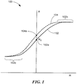
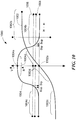
- graph 100 has a horizontal axis with a scale in units of magnetic field in arbitrary units.
- the graph 100 also has a vertical axis with a scale in units of resistance in arbitrary units.
- a curve 102 is representative of a resistance versus magnetic field transfer function of a magnetoresistance element at a nominal temperature.
- the curve 102 intersects the vertical axis at a point 102a, Ro, which is representative of a nominal resistance of the magnetoresistance element when the magnetoresistance element experiences a zero magnetic field.
- the curve 104 is representative of a resistance versus magnetic field transfer function of the same magnetoresistance element but at a different temperature.
- the curve 104 intersects the vertical axis at a .104a, which is representative of a different resistance of the magnetoresistance element at the different temperature when the magnetoresistance element experiences a zero magnetic field.
- the transfer curve 102 has an upper saturation region 102b and a lower saturation region 102c, within which resistance of the magnetoresistance element does not change very much with respect to magnetic field.
- the transfer curve also has a linear region between the two saturation regions 102b, 102c.
- the shape of the transfer curve 102, and, in particular, resistances at the saturation regions 102b, 102c, depends on type of and construction details of the magnetoresistance elements.
- the sensed external magnetic field at which the magnetoresistance element saturates i.e., the bend points of the transfer function 102 is largely independent of temperature, and thus, does not tend to drift.
- the sensed external magnetic field for a GMR of a TMR magnetoresistance element at saturation can be adjusted with various design parameters.
- the sensed external magnetic field at which saturation begins can be determined in-part by way of a width of the GMR magnetoresistance element and also by way of a thickness of a free layer used in the layer stack of the GMR magnetoresistance element.
- crystalline anisotropy induced by deposition details can in-part determine the saturation point.
- double pinned arrangements can in-part determine the saturation point by setting an amount of partial coupling between a second pinning layer and a free layer.
- a magnetoresistance element has a directional maximum response axis.
- the resistance of the magnetoresistance element moves to the right on the transfer curve 102, e.g., to a higher resistance.
- the resistance of the magnetoresistance element moves to the left on the transfer curve 102, e.g., , to a lower resistance.
- Circuits and techniques described below can determine a slope of the curve 102 at whatever magnetic fields the magnetoresistance element experiences. It will be apparent that the slope is relatively high at or near zero magnetic field, i.e., near the point 102a. It will also be apparent that the slope is relatively low in the saturation regions 102b, 102c.
- Determination of slope results from a mixing behavior of a magnetoresistance element, i.e., mixing an AC mixing magnetic field with frequency f1 with an AC mixing current drive signal applied to the magnetoresistance element with a frequency f2.
- Mixing of magnetoresistance elements is described in published PCT application WO 2007/095971 and in U.S. Published Application 2009/0206831, published August 20, 2009 .
- the DC term is proportional to the slope ⁇ of the transfer curve.
- a square wave signal at frequency, f includes frequency components (sinusoids) at the frequency, f, and at odd harmonics thereof.
- AC mixing currents and/or AC mixing magnetic fields used in the mixing process can be sinusoids.
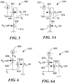
- Circuits in FIGS. 2 and 2A , 5 and 5A , 6 and 6A , 7 and 7A, and 8 and 8A are first described below in static terms, with DC (static) drive currents and with DC (static) magnetic fields. However, it is also described below that the circuits in FIGS. 2 and 2A , 5 and 5A, 6 and 6A , 7 and 7A, and 8 and 8A can be alternated, in which case, the drive currents and the magnetic fields are AC alternating signals, and mixing occurs.
- a circuit 200 includes a magnetoresistance element 202 driven with a static drive current generated by a current source 204. Under these conditions, the magnetoresistance element 202 experiences a static magnetic field in a direction 206 generated by current from the current source 204.
- the magnetoresistance element 202 does not experience a zero magnetic field, and therefore, does not have the nominal resistance, Ro, indicated in FIG. 1 . Instead, the resistance of the magnetoresistance element 202 can be Ro + ⁇ R.
- a circuit 210 is similar to the circuit 200 of FIG. 2 , but includes a current source 212 generating a static drive current in a direction opposite from the current source 204. Under these conditions, the magnetoresistance element 202 experiences a static magnetic field in a direction 206 generated by the drive current from the current source 212. The direction 214 is opposite from the direction 206 of FIG. 2 .
- the magnetoresistance element 202 again does not experience a zero magnetic field and does not have the nominal resistance, Ro, indicated in FIG. 1 .
- the resistance of the magnetoresistance element 202 can be Ro - ⁇ R.
- the circuits 200, 210 are considered to be the same circuit and the current sources 204, 212 are instead considered to be one current source that switches direction of the drive current I, resulting in an AC mixing current, and therefore, also switches direction of the resulting self-generated AC mixing magnetic field.
- graph 300 has a horizontal axis with a scale in units of magnetic field in arbitrary units.
- the graph 300 also has a vertical axis with a scale in units of resistance in arbitrary units.
- a curve 302 is representative of a resistance versus magnetic field transfer function of a magnetoresistance element at a nominal temperature.
- the curve 302 has saturation regions 302a, 302b in which the resistance changes little when the sensed external magnetic field changes.
- the curve 302 intersects the vertical axis at a point 304, Ro, which is representative of a nominal resistance of the magnetoresistance element when the magnetoresistance element experiences a zero sensed external magnetic field.
- resistances at points 306, 308 are Ro + ⁇ R and Ro - ⁇ R, respectively.
- graph 320 has a horizontal axis with a scale in units of magnetic field in arbitrary units.
- the graph 320 also has a vertical axis with a scale in units of resistance in arbitrary units.
- a curve 328 is representative of a resistance versus magnetic field transfer function of a magnetoresistance element at a nominal temperature.
- the curve 328 has saturation regions 328a, 328b in which the resistance changes little when the external magnetic field changes.
- the curve 328 intersects the vertical axis at a point 330, Ro, which is representative of a nominal resistance of the magnetoresistance element when the magnetoresistance element experiences a zero sensed external magnetic field.
- the magnetoresistance element When the magnetoresistance element experiences a sensed external magnetic field having a field of HI, the magnetoresistance element operates about a point 322, which can be in the saturation region 328a.
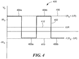
- a graph 400 has a horizontal axis with a scale in units of time in arbitrary units and a vertical axis with a scale in units of voltage in arbitrary units.
- a curve 402 has high states 404a, 404b and low states 406a, 406b with voltages according to equations (4) and (5), respectively.
- the DC voltage of equation (7) is generated in the presence of a zero sensed external magnetic field.
- the DC voltage of equation (7) is indicative of a slope of the transfer function 302 of FIG. 3 in the vicinity of the points 306, 308 and is an outcome of the above-described mixing of equations (1) to (3).
- the points 306, 308 move to the right or to the left on the transfer curve 302 when the magnetoresistance element 302 of FIGS. 2 and 2A experiences a sensed external magnetic field.
- the voltage of equation (7) remains generally invariant until the points 306, 308 approach one of the saturation regions 302a, 302b due to the presence of the sensed external magnetic field of sufficient magnitude, at which point the DC voltage or DC voltage component becomes approximately zero.
- a circuit 500 includes a first magnetoresistance element 502 coupled in series with a second magnetoresistance element 504, driven with a static drive current generated by a current source 506.
- the first and second magnetoresistance elements 502, 504 are driven with the same static drive current, but flowing in opposite physical directions due to arrangement of the two magnetoresistance elements 502 504 upon a substrate.
- the first magnetoresistance element 502 experiences astatic magnetic field in a direction 508 generated by current from the current source 506.
- the second magnetoresistance element 504 experiences a static magnetic field in a direction 510 (opposite from the direction 508) generated by the current from the current source 506.
- the first and second magnetoresistance elements 502, 504 do not experience a zero magnetic field and do not have the nominal resistance, Ro, indicated in FIG.1 .
- the resistance of the first magnetoresistance element 502 can be Ro - ⁇ R.
- the resistance of the second magnetoresistance element 504 can be Ro + ⁇ R.
- a circuit 520 is like the circuit 500 of FIG. 5 , except that a current source 522 generates a current in an opposite direction from the current generated by the current source 506 of FIG. 5 .
- the first magnetoresistance element 502 experiences a static magnetic field in a direction 524 generated by current from the current source 522.
- the second magnetoresistance element 504 experiences a static magnetic field in a direction 526 (opposite from the direction 524) generated by the current from the current source 522.
- the first and second magnetoresistance elements 502, 504 do not experience a zero magnetic field and do not have the nominal resistance, Ro, indicated in FIG. 1 .
- the resistance of the first magnetoresistance element 502 can be Ro + ⁇ R.
- the resistance of the second magnetoresistance element 504 can be Ro - ⁇ R.
- the circuits 500, 520 are considered to be the same half bridge circuit and the current sources 506, 522 are instead considered to be one current source that switches direction of the drive current I, resulting in an AC mixing current, and therefore, also switches direction of the resulting magnetic field, resulting in a self-generated AC mixing magnetic field.
- a circuit 600 includes a first magnetoresistance element 602 coupled in series with a second magnetoresistance element 604, driven with a static drive current generated by a current source 606.
- the first and second magnetoresistance elements 602, 604 are driven with the same static drive current, but flowing in opposite physical directions due to arrangement of the two magnetoresistance elements 602 604 upon a substrate.
- the first and second magneto resistance element 602, 604 are differently arranged, as shown, on a substrate than the first and second magnetoresistance elements 502, 504 of FIGS.5 and 5A .
- the first magnetoresistance element 602 experiences a static magnetic field in a direction 608 generated by current from the current source 606.
- the second magnetoresistance element 604 experiences a static magnetic field in a direction 610 (opposite from the direction 608) generated by the current from the current source 606.
- the first and second magnetoresistance elements 602, 604 do not experience a zero magnetic field and do not have the nominal resistance, Ro, indicated in FIG. 1 .
- the resistance of the first magnetoresistance element 602 can be Ro + ⁇ R.
- the resistance of the second magnetoresistance element 604 can be Ro - ⁇ R.
- a circuit 620 is like the circuit 600 of FIG.6 , except that a current source 622 generates a current in an opposite direction from the current generated by the current source 606 of FIG. 6 .
- the first magnetoresistance element 602 experiences a static magnetic field in a direction 624 generated by current from the current source 622.
- the second magnetoresistance element 604 experiences a static magnetic field in a direction 626 (opposite from the direction 624 generated by the current from the current source 622.
- the first and second magnetoresistance elements 602, 604 do not experience a zero magnetic field and do not have the nominal resistance, Ro, indicated in FIG. 1 .
- the resistance of the first magnetoresistance element 602 can be Ro - ⁇ R.
- the resistance of the second magnetoresistance element 604 can be Ro + ⁇ R.
- the circuits 600, 620 are considered to be the same half bridge circuit and the current sources 606, 622 are instead considered to be one current source that switches direction of the drive current I, and therefore, also switches direction of the resulting in an AC mixing current, and also resulting in a self-generated AC mixing magnetic field.
- the circuits 500, 520 are also considered to be the same half bridge circuit and the current sources 506, 522 are instead considered to be one current source that switches direction of the drive current I, resulting in an AC mixing current, and also resulting in a self-generated AC mixing magnetic field.
- circuit(s) of FIGS. 5 and 5A can form one half bridge of a full bridge circuit and the circuit(s) of FIGS. 6 and 6A can form the other half bridge of a full bridge circuit.
- An outcome of the full bridge circuit is described below in conjunction with FIG. 9B .
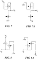
- equations (8)-(23) above it is assumed that the voltage VA remains constant, the nominal value (center operating point) of magnetoresistance elements is Ro, and the sensed external magnetic field is zero. This assumption is not true when the magnetoresistance element experiences a non-zero sensed external magnetic field, in which case the nominal resistance of the magnetoresistance elements changes. However, it will become apparent from discussion below in conjunction with FIGS. 9-9B that, in operation, the nominal resistance terms (either Ro or some other resistance) cancel, leaving only a ⁇ R terms, and equations (8)-(23) above provide a correct average DC value for half bridge circuits and for full bridge circuits.
- circuits are similar to the circuits of FIGS. 5, 5A, 6, and 6A .
- voltage sources VA are used to drive the various circuits instead of current sources.
- the voltages labeled VA in FIGS. 5A and 6A are shown in equations 12 and 20 to be negative voltages, the same drive is achieved in the circuits of FIGS. 7A and 8A by positive voltages VA at the opposite end of the magnetoresistance elements.
- the magnetoresistance elements for the half bridge arrangements can be driven with either current sources or with voltage sources to achieve the same results described more fully below.
- graphs 900, 920, 940 each have a respective horizontal axis with a scale in units of time in arbitrary units.
- the graphs 900, 920, 940 also each have a respective vertical axis with a sale in units of volts in arbitrary units.
- the graph 900 has a signal 902 with alternating high states 904a, 904b and low states 906a, 906b. Voltages at the two states are in accordance with the circuits of FIGS. 5 and 5A or FIGS. 7 and 7A (each taken as one respective circuit driven with and AC mixing current having alternating directions), which are in accordance with equations (11) and (15).
- the graph 920 has a signal 922 with alternating high states 924a, 924b and low states 926a, 926b. Voltages at the two states are in accordance with the circuits of FIGS. 6 and 6A or FIGS. 8 and 8A (each taken as one respective circuit driven with and AC mixing current having alternating directions), which are in accordance with equations (19) and (23).
- the graph 940 has a DC level 942 shown, which is representative of a difference between the signals 902 and 922.
- Vdc 2 ⁇ I ⁇ ⁇ ⁇ R , which is double the average (DC) value of the signals 902 and 922.
- the above difference can be physically achieved if the circuit(s) of FIGS. 5 and 5A (see, e.g., FIG. 9 ) forms one half bridge part of a full bridge circuit and the circuit(s) of FIGS. 6 (see, e.g., FIG. 9A ) and 6A forms the other half bridge part of the full bridge circuit.
- the difference can be physically achieved if the circuit(s) of FIGS. 7 and 7A (see, e.g., FIG. 9 ) forms one half bridge part of a full bridge circuit and the circuit(s) of FIGS. 8 and 8A (see, e.g., FIG. 9A ) forms the other half bridge part of the full bridge circuit.
- a full bridge circuit generates a differential signal.
- a residual AC voltage 944 can remain as a result of possible small mismatches between the two half bridge circuits, i.e., small mismatches between the two signals 902, 922, resulting from physically different magnetoresistance elements used in the two half bridge circuits.
- the AC signal 944 can be removed with a low pass filter or the like, leaving only the DC voltage 942.
- the DC voltage 942 is related to a slope of the region of the transfer curve 102 of FIG. 1 in which the magnetoresistance elements operate. As described above, the operating region is influenced by a sensed external magnetic field.
- the voltage signal generated by the half bridge circuits of FIGS. 5, 5A, 6, 6A , 7, 7A, 8, 8A (and also by the single element circuit of FIGS 2 and 2A ) has both a DC component and an AC component. It will also be apparent that the signal 942 generated by the full bridge circuit has primarily a DC signal component, but can also have an AC signal component due to element mismatches.
- the AC component of the output signals can be removed with a low pass filter or the like.
- a graph 1000 has a horizontal axis with a scale in units of magnetic field strength in arbitrary units.
- the graph 1000 also has a vertical axis with a scale in units of volts in arbitrary units and in resistance in arbitrary units.
- a curve 1002 like the curve 102 of FIG. 1 , again shows a transfer characteristic of a magnetoresistance element.
- the curve 1002 has an upper saturation region 1002b and a lower saturation region 1002c.
- a point 1002a on the curve 1002 is representative of a resistance of the magnetoresistance element when the magnetoresistance element experiences a zero sensed external magnetic field (and has no AC mixing magnetic field).
- a curve 1004 is representative of the DC voltage signal 942 of FIG. 9B for a full bridge circuit, or of a DC signal component of any of the above-described half bridge or single element magnetoresistance element circuits, that experience mixing, as the magnetoresistance element(s) experiences different sensed external magnetic fields, moving the operating region to the right or to the left on the transfer curve 1002.
- the DC output voltage or DC output voltage components of the above described circuits when mixing occurs, is representative of a slope of the transfer curve 1002 in the region that a sensed magnetic field operates in the transfer curve 1002.
- the resulting DC voltage or DC voltage components is represented by relatively flat region 1004d of the curve 1004, i.e., a non-zero value.
- the resulting DC voltage or DC voltage component is represented by the region 1004b of the curve 1004, i.e., an approximately zero value.
- the resulting DC voltage or DC voltage component is represented by the region 1004c of the curve 1004, i.e., an approximately zero value.
- the above-described mixed magnetoresistance element circuits can function as magnetic switches or proximity detectors to sense the presence, absence, or proximity of a magnetic (or ferromagnetic) object that generates a sensed external magnetic field.
- Circuits described below can use one or two thresholds 1006, 1008, e.g., an operating point threshold, Bop, 1008 and/or a release point threshold, Brp, 1006 and can compare the DC signal 1004 with the threshold(s) to sense the presence, absence, or proximity of a magnetic (or ferromagnetic) object.
- FIGS. 11-15 show magnetic field sensors and associated circuits that use one magnetoresistance element, two magnetoresistance elements coupled in a half bridge arrangement, and four magnetic magnetoresistance elements coupled in a full bridge arrangement.
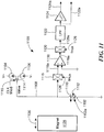
- a magnetic field sensor 1100 can include one magnetoresistance element 1102.
- the magnetoresistance element 1102 can have a directional maximum response axis 1102a.
- the magnetoresistance element 1102 can be driven with an AC mixing current 1108 having alternating directions by first and second current sources 1104, 1106, respectively, coupled to the magnetoresistance element 1102 via a switch 1114.
- the switch 1114 is coupled to receive a modulated clock signal 1115.
- the AC mixing current 1108 passing through the magnetoresistance element 1102 causes a self-generated AC mixing magnetic field directed in two directions 1110, 1112 in accordance with the two directions of the AC mixing current 1108.
- a frequency, f, of the AC mixing current 1108 is the same as a frequency, f, of the self-generated AC mixing magnetic field having directions 1110, 1112.
- a voltage signal 1108 with a DC component is generated at the top end of the magnetoresistance element 1102.
- a multiplexer 1116 is coupled to receive the voltage signal 1108 and configured to generate a multiplexed signal 1116a.
- An amplifier 1118 can be coupled to receive the multiplexed signal 1116a and configured to generate an amplified signal 1118a.
- a demultiplexer 1120 can be coupled to receive the amplified signal 1118a and configured to generate a multiplexed signal 1120a.
- a low pass filter 1122 can be coupled to receive the multiplexed signal 1120a and configured to generate a filtered signal 1122a.
- a comparator 1124 for example, a Schmidt trigger, having two thresholds, can be coupled to receive the filtered signal 1122a and configured to generate a comparison signal 1124a.
- the first multiplexer 1116 and the second multiplexer 1120 can essentially provide a chopping surrounding the amplifier1118.
- Chopper stabilization is a known technique to reduce the effects of offset voltage, i.e., unwanted DC voltage, of the amplifier 1118.
- the chopping can operates with a clock signal 1126 with a frequency higher than a frequency of a cock 1115 that modulates a current 1208.
- the low pass filter 1122 can remove an AC signal component, for example, the AC signal component of the signal 402 of FIG. 4 , leaving only the DC component, for example, the DC component 412 of FIG. 4 .
- the comparison signal 1124a takes on a first state, for example, a low state.
- the comparison signal 1124a takes on the second state, for example, a high state. This operation should be understood from the discussion above in conjunction with FIG. 10 .
- the movement need not be along a straight line or along a line parallel to the maximum response axis 1102a.
- the filtered signal 1122a does not take on only two states, but instead, takes on a range of values in accordance with the curve 1004 FIG. 10 .
- the magnetic field sensor 1100 does not necessarily include a magnet 1128. Electronic components shown as the magnetic field sensor 1100 can be disposed upon a common semiconductor substrate.
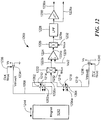
- a magnetic field sensor 1200 can include first and second magnetoresistance elements 1202, 1204, respectively, coupled in half bridge arrangement.
- the first magnetoresistance element 1202 can have a directional maximum response axis 1202a
- the second magnetoresistance element 1204 can have a directional maximum response axis 1204a in the same direction as the directional maximum response axes 1202a.
- the first and second magnetoresistance elements 1202, 1204 can be fabricated exactly the same way and oriented in exactly the same direction upon a semiconductor substrate.
- the first and second magnetoresistance elements 1202, 1204 can be driven with an AC mixing current 1208 (also 1210) having alternating directions by first and second voltage sources formed by first and second switches 1234, 1238 coupled to a voltage, Vs, and to ground.
- the first and second switches 1234, 1238 can be coupled as shown to the first and second magnetoresistance elements 1202, 1204 such that the current flows in one direction through the first magnetoresistance element 1202 and in an opposite physical direction through the second magnetoresistance element 1204.
- This coupling is the same as or similar to the coupling shown in half bridge circuits of FIGS. 5, 5A , 7, and 7A . However, in other embodiments, the coupling arrangement of FIGS. 6, 6A , 8, 8A could instead be used.
- the SC mixing current 1208 (also 1210) passing through the first and second magnetoresistance elements 1202, 1204 causes respective self-generated AC mixing magnetic fields directed in directions 1112, 1114 at the first magnetoresistance element 1202 and directed in directions 1216, 1218 at the second magnetoresistance element 1204 (one hundred eighty degrees out of phase) in accordance with the two directions of the AC mixing current 1208 (also 1210).
- a frequency, f, of the AC mixing current 1208 (also 1210) is the same as a frequency, f, of the self-generated AC mixing magnetic fields having directions 1212, 1214, 1216, 1218.
- a voltage signal 1220a with a DC component is generated at a junction of the two magnetoresistance elements 1202, 1204.
- a multiplexer 1222, an amplifier 1224, a demultiplexer 1226, a low pass filter 1228, and a comparator 1230 can be the same as or similar to the multiplexer 1116, the amplifier 1118, the demultiplexer 1120, the low pass filter 1122, and the comparator 1124 of FIG. 11 .
- Signals 1220a, 1222a, 1224a, 1226a, 1228a, 1230a are the same as or similar to signals 1116a, 1118a, 1120a, 1122a, and 1124a, respectively.
- the amplifier 1224 can be biased with a bias signal 1228.
- the low pass filter 1228 can remove an AC signal component, for example, the AC signal component of the signal 902 of FIG. 9 , leaving only the DC component, for example, the DC component of FIG. 9 .
- Sensing of a magnet 1242 is the same as or similar to the sensing of the magnet 1128 described above in conjunction with FIG. 11 .
- An example of movement of the magnet 1242 is shown by a line 1244. However, the movement need not be along a straight line or along a line parallel to the maximum response axes 1202a, 1204a.
- the magnetic field sensor 1200 does not necessarily include a magnet 1242. Electronic components shown as the magnetic field sensor 1200 can be disposed upon a common semiconductor substrate.
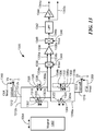
- a magnetic field sensor 1300 can have a first half bridge comprised of first and second magnetoresistance elements 1302, 1304, respectively, coupled in series, and a second half bridge comprised of third and fourth magnetoresistance elements 1306, 1308, respectively, coupled in series.
- the first magnetoresistance element 1302 can have a directional maximum response axis 1302a
- the second magnetoresistance element 1304 can have a directional maximum response axis 1304a in the same direction as the directional maximum response axes 1302a.
- the first and second magnetoresistance elements 1302, 1304 can be fabricated exactly the same way and oriented in exactly the same direction upon a semiconductor substrate.
- the third magnetoresistance element 1306 can have a directional maximum response axis 1306a
- the fourth magnetoresistance element 1308 can have a directional maximum response axis 1308a in the same direction as the directional maximum response axis 1306a.
- the third and fourth magnetoresistance elements 1306, 1308 can be fabricated exactly the same way and oriented in exactly the same direction.
- the first, second, third, and fourth magnetoresistance elements 1302, 1304, 1306, 1308, respectively can all be fabricated exactly the same way and oriented in exactly the same direction upon the same semiconductor substrate.
- the first and second magnetoresistance elements 1302, 1304 can be driven with an AC mixing current 1312 (also 1316), that splits between currents 1312a (also 1316a) and 1312b (also 1316b).
- the current splitting can be equal if the two half bridge circuits have exactly the same resistances. However, if the two half bridge circuits do not have exactly the same resistances, the current splitting is not exactly equal and may contribute to the AC signal component 944 of FIG. 9B .
- the AC mixing currents 1312a (and also 1316a) and 1312b (and also 1316b) are separately generated.
- the separately generated AC mixing currents have different frequencies but achieve the same mixing effect described herein.
- the AC mixing current 1312 (also 1316) has alternating directions by first and second voltage sources formed by first and second switches 1310, 1314 coupled to a voltage, Vs, and to ground.
- the first and second switches 1310, 1314 can be coupled as shown to the first, second, third, and fourth magnetoresistance elements 1302, 1304, 1306, 1308.
- the AC mixing current 1312a (also 1316a) flows in one direction through the first magnetoresistance element 1302 and in an opposite physical direction through the second magnetoresistance element 1304.
- the current 1312b (also 1316b) flows in one direction through the third magnetoresistance element 1306 and in an opposite physical direction through the fourth magnetoresistance element 1308.
- This coupling is the same as or similar to the coupling shown in half bridge circuits of FIGS. 5, 5A, 6, and 6A and also in FIGS. 7, 7A, 8, 8A .
- the AC mixing current 1312a (also 1316a) passing through the first and second magnetoresistance elements 1302, 1304 causes respective self-generated AC mixing magnetic fields directed in directions 1318, 1320 at the first magnetoresistance element 1302 and directed in directions 1322, 1324 at the second magnetoresistance element 1304 (one hundred eighty degrees out of phase) in accordance with the two directions of the alternating current 1312a (also 1316a).
- the modulated current drive 1312b (also 1316b) passing through the third and fourth magnetoresistance elements 1306, 1308 causes respective self-generated AC mixing magnetic fields directed in directions 1326, 1328 at the third magnetoresistance element 1306 and directed in directions 1330, 1332 at the fourth magnetoresistance element 1308 (one hundred eighty degrees out of phase) in accordance with the two directions of the alternating current 1312b (also 1316b).
- a frequency, f, of the AC mixing current 1312 (also 1316) is the same as a frequency, f, of the self-generated AC mixing magnetic fields having directions 1318, 1320, 1322, 1324, 1326, 1328, 1330, 1330.
- a differential voltage signal 1334a, 1334b with a DC component is generated at a junction of the two magnetoresistance elements 1302, 1304.
- a multiplexer 1336, an amplifier 1338, a demultiplexer 1340, a low pass filter 1342, and a comparator 1344 are the same as or similar to the multiplexer 1116, the amplifier 1118, the demultiplexer 1120, the low pass filter 1122, and the comparator 1124 of FIG. 11 .
- Signals 1334a and 1334b, 1336a and 1336b, 1338a, 1340a, 1342a, 1344a are the same as or similar to signals 1116a, 1118a, 1120a, 1122a, and 1124a, respectively.
- the amplifier 1338 is a differential amplifier with two input nodes.
- the low pass filter 1342 can remove an AC signal component, for example, the AC signal component 944 of FIG. 9B , leaving only the DC component, for example, the DC component of 942 FIG. 9 .
- Sensing of a magnet 1352 is the same as or similar to the sensing of the magnet 1128 described above in conjunction with FIG. 11 .
- An example of movement of the magnet 1352 is shown by a line 1354. However, the movement need not be along a straight line or along a line parallel to the maximum response axes 1302a, 1304a, 1306a, 1308a.
- the magnetic field sensor 1300 does not necessarily include a magnet 1352. Electronic components shown as the magnetic field sensor 1300 can be disposed upon a common semiconductor substrate.
- a magnetic field sensor 1400 can have a first half bridge comprised of first and second magnetoresistance elements 1402, 1404, respectively, coupled in series, and a second half bridge comprised of third and fourth magnetoresistance elements 1406, 1408, respectively, coupled in series to form a full bridge circuit.
- the first, second, third, and fourth magnetoresistance elements 1402, 1404, 1406, 1408, respectively, can all be fabricated exactly the same way and oriented in exactly the same direction upon a common semiconductor substrate.
- the first and second magnetoresistance elements 1402, 1404 can be driven with an AC mixing current 1434 (also 1440), that splits between currents 1434a (also 1440a) and 1434b (also 1440b).
- the AC mixing current has alternating directions by first and second voltage sources formed by first and second switches 1432, 1438 coupled to a voltage, Vs, and to ground.
- the first and second switches 1432, 1448 can be coupled as shown to the first, second, third, and fourth magnetoresistance elements 1402, 1404, 1406, 1408.
- the AC mixing current 1434a (also 1440a) flows in one direction through the first magnetoresistance element 1402 and in an opposite physical direction through the second magnetoresistance element 1404.
- the current 1434b (also 1440b) flows in one direction through the third magnetoresistance element 1406 and in an opposite physical direction through the fourth magnetoresistance element 1408.
- This coupling is the same as or similar to the coupling shown in half bridge circuits of FIGS. 5, 5A, 6, and 6A and also in FIGS. 7, 7A, 8, 8A .
- the magnetic field sensor 1400 can include current conductors 1410, 1412, 1414, 1416 proximate to the first, second, third, and fourth magnetoresistance elements 1402, 1404, 1406, 1408, respectively.
- the current conductors 1410, 1412, 1414, 1416 are coupled in series in such a way that an alternating current 1452 (also 1454) flowing through the current conductors generate externally-generated AC mixing magnetic fields at the first, second, third, and fourth magnetoresistance elements 1402, 1404, 1406, 1408, that add to the above-described self-generated AC mixing magnetic fields.
- the alternating current 1452 (also 1454) can be generated, for example, by current sources 1446, 1450 coupled though switches 1444, 1448, respectively, to opposite ends of the series coupled current conductors 1410, 1412, 1414, 1416 .
- the combined AC mixing magnetic fields are alternating magnetic fields that operate in the same way as the above-described self-generated AC mixing magnetic fields to provide mixing.
- the externally-generated AC mixing magnetic fields generated by the current conductors 1410, 1412, 1414, 1416 can be larger than the self-generated AC mixing magnetic fields resulting in larger values of ⁇ R in equations above and larger resulting DC voltages or DC voltage components.
- the externally-generated AC mixing magnetic fields are at the same phases (and frequency) as the self-generated AC mixing magnetic fields at each magnetoresistance element.
- a multiplexer 1420, an amplifier 1422, a demultiplexer 1424, a low pass filter 1426, and a comparator 1428 are the same as or similar to the multiplexer 1116, the amplifier 1118, the demultiplexer 1120, the low pass filter 1122, and the comparator 1124 of FIG. 11 .
- Signals 1418a and 1418b, 1420a and 1420b, 1422a, 1424a, 1426a, 1428a are the same as or similar to signals 1116a, 1118a, 1120a, 1122a, and 1124a, respectively.
- the amplifier 1422 is a differential amplifier with two input nodes.
- the low pass filter 1426 can remove an AC signal component, for example, the AC signal component 944 of the signal 940 of FIG. 9B , leaving only the DC component, for example, the DC component of 942 FIG. 9 .
- Sensing of a magnet 1456 is the same as or similar to the sensing of the magnet 1128 described above in conjunction with FIG. 11 .
- An example of movement of the magnet 1456 is shown by a line 1458. However, the movement need not be along a straight line or along a line parallel to the maximum response axes of the magnetoresistance elements 1402, 1404, 1406, 1408.
- the magnetic field sensor 1400 does not necessarily include a magnet 1456. Electronic components shown as the magnetic field sensor 1400 can be disposed upon a common semiconductor substrate.
- a magnetic field sensor 1500 can have a first half bridge comprised of first and second magnetoresistance elements 1502, 1504, respectively, coupled in series, and a second half bridge comprised of third and fourth magnetoresistance elements 1506, 1508, respectively, coupled in series to form a full bridge circuit.
- the first, second, third, and fourth magnetoresistance elements 1502, 1504, 1506, 1508, respectively, can all be fabricated exactly the same way and oriented in exactly the same direction upon a common semiconductor substrate.
- the first and second magnetoresistance elements 1502, 1504 can be driven with an AC mixing current 1534 (also 1540), that splits between currents 1534a (also 1540a) and 1534b (also 1540b).
- the AC mixing current has alternating directions by first and second voltage sources formed by first and second switches 1532, 1538 coupled to a voltage, Vs, and to ground.
- the first and second switches 1532, 1548 can be coupled as shown to the first, second, third, and fourth magnetoresistance elements 1502, 1504, 1506, 1508.
- the AC mixing current 1534a (also 1540a) flows in one direction through the first magnetoresistance element 1502 and in an opposite physical direction through the second magnetoresistance element 1504.
- the current 1534b (also 1540b) flows in one direction through the third magnetoresistance element 1506 and in an opposite physical direction through the fourth magnetoresistance element 1508.
- This coupling is the same as or similar to the coupling shown in half bridge circuits of FIGS. 5, 5A, 6, and 6A and also in FIGS. 7, 7A, 8, 8A .
- the magnetic field sensor 1500 can include current conductors 1510, 1512, 1515, 1516 proximate to the first, second, third, and fourth magnetoresistance elements 1502, 1504, 1506, 1508, respectively.
- the current conductors 1510, 1512, 1514, 1516 are coupled in series in such a way that an alternating current 1552 (also 1554) flowing through the current conductors generates externally-generated AC mixing magnetic fields at the first, second, third, and fourth magnetoresistance elements 1502, 1504, 1506, 1508, that add to the above-described self-generated AC mixing magnetic fields.
- the current conductors 1510, 1512, 1514, 1516 are coupled in series with the AC mixing currents 1534a (also 1540a) and 1534b (also 1540b), and no additional drive circuitry is need to drive the currents through the current conductors 1510, 1512, 1514, 1516. This arrangement saves power when compared to the magnetic field sensor 1400 of FIG. 14 .
- the combined AC mixing magnetic fields are alternating magnetic fields that operate in the same way as the above-described self-generated AC mixing magnetic fields to provide mixing.
- the external AC mixing magnetic fields generated by the current conductors 1510, 1512, 1515, 1516 can be larger than the self-generated AC mixing magnetic fields resulting in larger values of ⁇ R in equations above and larger resulting DC voltages or DC voltage components.
- the external AC mixing magnetic fields are at the same phases (and frequency) as the self-generated AC mixing magnetic fields at each magnetoresistance element.
- a multiplexer 1520, an amplifier 1522, a demultiplexer 1524, a low pass filter 1526, and a comparator 1528 are the same as or similar to the multiplexer 1116, the amplifier 1118, the demultiplexer 1120, the low pass filter 1122, and the comparator 1124 of FIG. 11 .
- Signals 1518a and 1518b, 1520a and 1520b, 1522a, 1524a, 1526a, 1528a are the same as or similar to signals 1116a, 1118a, 1120a, 1122a, and 1124a, respectively.
- the amplifier 1522 is a differential amplifier with two input nodes.
- the low pass filter 1526 can remove an AC signal component, for example, the AC signal component 944 of the signal 944 of FIG. 9B , leaving only the DC component, for example, the DC component of 942 FIG. 9 .
- Sensing of a magnet 1544 is the same as or similar to the sensing of the magnet 1128 described above in conjunction with FIG. 11 .
- An example of movement of the magnet 1544 is shown by a line 1546. However, the movement need not be along a straight line or along a line parallel to the maximum response axes of the magnetoresistance elements 1502, 1504, 1506, 1508.
- the magnetic field sensor 1500 does not necessarily include a magnet 1544. Electronic components shown as the magnetic field sensor 1500 can be disposed upon a common semiconductor substrate.
- the current conductors 1410, 1412, 1414, 1416 of FIG. 14 and/or the current conductors 1510, 1512, 1516, 1518 of FIG. 15 can each be comprised of one or more loops in a semiconductor substrate, where each loop in formed in a different metal layer, e.g., M1, M2, M3 of the semiconductor substrate.
- Crosshatched patches represent current conductor portions, each under or over a respective magnetoresistance element 1602.
- Magnetic field sensors used as proximity detectors or magnetic switches are described above. Each magnetic field sensor above is configured to sense a proximity of a magnetic object, e.g., a magnet. Circuits below use similar circuits to detect a speed of rotation of a magnetic or of a ferromagnetic object.
- a magnetic field sensor 1700 includes a magnetoresistance element bridge 1706 (or a single element) configured to generate a sensed signal 1706a.
- Electronics 1708 is coupled to receive the sensed signal 1706a and configured to generate an output signal. 1708a.
- the magnetoresistance element bridge 1706 (or a single element) can be the same as or similar to any of the magnetoresistance element arrangements described above.
- the electronics 1708 can be the same as or similar to any of the electronic components described above.
- the magnetic field sensor 1700 can also include an outer package 1702, for example, a plastic or a molded package.
- the magnetic field sensor can provide the output signal 1708a indicative of proximity of north and south poles of a ring magnet 1712, with transitions at a rate proportional to a speed of rotation of the ring magnet 1712.
- Magnetic field sensors that sense a movement or position of a line magnet having alternating north and south poles can operate in a similar way.
- a magnetic field sensor 1800 includes a magnetoresistance element bridge 1806 (or a single element) coupled to generate a sensed signal 1806a.
- Electronics 1808 is coupled to receive the sensed signal 1806a and configured to generate an output signal 1808a.
- the magnetic field sensor 180 can include a permanent magnet 1810 that makes a DC magnetic field in the vicinity of the magnetoresistance element bridge (or single element).
- the magnetoresistance element bridge 1806 (or a single element) can be the same as or similar to any of the magnetoresistance element arrangements described above.
- the electronics 1808 can be the same as or similar to any of the electronic components described above.
- the magnetic field sensor 1800 can also include an outer package 1802, for example, a plastic or a molded package.
- the magnetic field sensor 1800 can provide the output signal 1808a indicative of proximity of teeth, e.g., 1814, of a ferromagnetic gear 1812, with transitions at a rate proportional to a speed of rotation of the ferromagnetic gear.
- the teeth alter a magnitude and a direction of the magnetic field proximate to the magnetoresistance element bridge 1806 (or a single element) generated by the magnet 1810.
- the magnet 1810 can within or upon or proximate to the package 1802.
- the electronic components can be disposed on more than one semiconductor substrate.
- the above-describe magnetoresistance elements can be disposed on a first semiconductor substrate and other identified electronic components can be disposed on a second different semiconductor substrate, wherein the two substrate have signal connections therebetween.
Description
- This invention relates generally to magnetoresistance elements, and, more particularly, to magnetic field sensors and methods that use mixing (or modulation) in a magnetoresistance element.
- As used herein, the term "magnetic field sensing element" is used to describe a variety of electronic elements that can sense a magnetic field. One such magnetic field sensing element is a magnetoresistance (MR) element. The magnetoresistance element has a resistance that changes in relation to a magnetic field experienced by the magnetoresistance element.
- As is known, there are different types of magnetoresistance elements, for example, a semiconductor magnetoresistance element such as Indium Antimonide (InSb), a giant magnetoresistance (GMR) element, an anisotropic magnetoresistance element (AMR), and a tunneling magnetoresistance (TMR) element, also called a magnetic tunnel junction (MTJ) element.
- As is known, metal based or metallic magnetoresistance elements (e.g., GMR, TMR, AMR) tend to have axes of sensitivity parallel to a substrate on which they are formed.
- As used herein, the term "magnetic field sensor" is used to describe a circuit that uses a magnetic field sensing element, generally in combination with other circuits. In a typical magnetic field sensor, the magnetic field sensing element and the other circuits can be integrated upon a common substrate.
- Magnetic field sensors are used in a variety of applications, including, but not limited to, an angle sensor that senses an angle of a direction of a magnetic field, a current sensor that senses a magnetic field generated by a current carried by a current-carrying conductor, a magnetic switch that senses the proximity of a ferromagnetic object, a rotation detector that senses passing ferromagnetic articles, for example, magnetic domains of a ring magnet or a ferromagnetic target (e.g., gear teeth) where the magnetic field sensor is used in combination with a back-biased or other magnet, and a magnetic field sensor that senses a magnetic field density of a magnetic field.
- GMR and TMR elements are known to have a relatively high sensitivity, compared, for example, to Hall elements. GMR and TMR elements are also known to have moderately good linearity, but over a restricted range of magnetic fields, more restricted in range than a range over which a Hall element can operate.
- The magnetoresistance element may be a single element or, alternatively, two or more magnetoresistance elements may be arranged in various configurations, e.g., a half bridge or full (Wheatstone) bridge.
- When arranged in a half bridge, usually one magnetoresistance element is used in series combination with one fixed resistor. If instead, two identical magnetoresistance elements were used, the half bridge would tend to have no output signal, since both magnetoresistance elements would tend to change resistance in the same direction in response to a magnetic field.
- When arranged in a full bridge, usually two magnetoresistance elements are used in two series combinations with two fixed resistors. If instead, four identical magnetoresistance elements were used, the full bridge would tend to have no output signal, since the four magnetoresistance elements would tend to change resistance in the same direction in response to a magnetic field.
- The above-described bridges that use fixed resistors in various arrangements have disadvantages. For example, the fixed resistors can have temperature coefficients that do not match the temperature coefficients of the magnetoresistance elements, and therefore, an output signal generated by the bridges may vary with respect to temperature.
- Even a single magnetoresistance element driven from a current source (high output impedance) has a temperature coefficient that results in an output signal generated by the single magnetoresistance element that may vary with respect to temperature.
- It would be desirable to provide a magnetoresistance element, half bridge, or full bridge, an output signal from which varies less with temperature. It would be desirable to provide a magnetic field sensor that uses the above described magnetoresistance element, half bridge, or full bridge.
-
JP 2000 055998 A -
WO 2015/058733 A1 discloses a contactless magnetic sensor for sensing a magnetic or electrically conductive object's position, the sensor comprising at least one excitation coil connected to a source of an alternating signal, a magnetic field sensor located in the cavity of the excitation coil, an amplifier, and an excitation modulator which is connected to the source. The source generates an alternating current which generates an alternating current magnetic field around the excitation coil that interacts with materials in the coil's vicinity. The output of the sensor may therefore be used for position detection, proximity detection or discrimination of materials in the coil's vicinity. - The present invention provides a magnetic field sensor as defined in claim 1 and a method of sensing a sensed external magnetic field as defined in claim 7.
- In accordance with an example useful for understanding an aspect of the present invention, a magnetic field sensor for sensing a sensed external magnetic field can include first, second, third, and fourth magnetoresistance elements arranged in a bridge, a first junction node coupling the first and second magnetoresistance elements in series and a second junction node coupling the third and fourth magnetoresistance elements in series, wherein the bridge generates a bridge output signal between the first and second junction nodes. The magnetic field sensor can further include at least one current generating circuit operable to generate first and second AC mixing currents, wherein the first AC mixing current is coupled to pass through the first and second series coupled magnetoresistance elements, wherein the second AC mixing current is coupled to pass through the third and fourth series coupled magnetoresistance elements, wherein the first and second AC mixing currents have first and second AC current components, respectively, with respective first and second AC current frequencies, which are the same frequency or which are different frequencies. The magnetic field sensor can further include at least one magnetic field generating circuit operable to generate first, second, third, and fourth AC mixing magnetic fields proximate to the first, second, third, and fourth magnetoresistance elements, respectively, wherein the first, second, third, and fourth AC mixing magnetic fields have first, second, third and fourth AC magnetic field components, respectively, wherein the first and second AC magnetic field components have a first AC magnetic field frequency the same as the first AC current frequency, wherein the third and fourth AC magnetic field components have a second AC magnetic field frequency the same frequency as the second AC current frequency, wherein the first, second, third, and fourth AC mixing magnetic fields result in the bridge output signal comprising a first DC component that changes value in response to changes of the sensed external magnetic field.
- In some embodiments, the above magnetic field sensor can include one or more of the following aspects in any combination.
- In some embodiments, the above magnetic field sensor further comprises:
a comparator coupled to receive a signal representative of the bridge output signal, where the comparator is operable to compare the signal representative of the bridge output signal with at least one threshold signal to generate a comparison signal having a first state indicative of a magnitude of the sensed external magnetic field being less than a first predetermined magnetic field magnitude and having a second state indicative of the magnitude of the sensed external magnetic field being greater than a selected one of the first predetermined magnetic field magnitude or a second different predetermined magnetic field magnitude. - In some embodiments, the above magnetic field sensor further comprises:
a filter coupled between the comparator and the first and second junction nodes, the filter selected to remove one or more AC components of the bridge output signal at one or more of the first and second magnetic field frequencies, wherein the filter is configured to generate a filtered signal, wherein the comparator is coupled to receive the filtered signal as the signal representative of the bridge output signal. - In some embodiments of the above magnetic field sensor, the at least one magnetic field generating circuit and the at least one current generating circuit are the same at least one dual-purpose circuit, wherein the first AC mixing current results in the first and second AC mixing magnetic fields, and wherein the second AC mixing current result in the third and fourth AC mixing magnetic fields.
- In some embodiments of the above magnetic field sensor, the at least one magnetic field generating circuit comprises:
- a first magnetic field source disposed proximate to the first magnetoresistance element;
- a second magnetic field source disposed proximate to the second magnetoresistance element;
- a third magnetic field source proximate to the third magnetoresistance element; and
- a fourth magnetic field source proximate to the fourth magnetoresistance element, wherein the first magnetic field source is configured to generate the first AC mixing magnetic field proximate to the first magnetoresistance element, wherein the second magnetic field source is configured to generate the second AC mixing magnetic field proximate to the second magnetoresistance element, wherein the third magnetic field source is configured to generate the third AC mixing magnetic field proximate to the third magnetoresistance element, and wherein the fourth magnetic field source is configured to generate the fourth AC mixing magnetic field proximate to the fourth magnetoresistance element.
- In some embodiments of the above magnetic field sensor, the bridge is arranged upon a substrate, wherein the first magnetic field source comprises a first current conductor disposed upon or within the substrate, the second magnetic field source comprises a second current conductor disposed upon or within the substrate, the third magnetic field source comprises a third current conductor disposed upon or within the substrate, and the fourth magnetic field source comprises a fourth current conductor disposed upon or within the substrate.
- In some embodiments of the above magnetic field sensor, the first and second current conductors are electrically coupled in series with the first and second magnetoresistance elements, and wherein the third and fourth current conductors are electrically coupled in series with the third and fourth magnetoresistance elements.
- In some embodiments of the above magnetic field sensor, the first, second, third, and fourth magnetic fields have directions within about +/- forty-five degrees of parallel to first, second, third, and fourth major response axes of the first, second, third, and fourth magnetoresistance elements, respectively.
- In accordance with an example useful for understanding another aspect of the present invention, a method of sensing a sensed external magnetic field can include providing first, second, third, and fourth magnetoresistance elements arranged in a bridge, a first junction node coupling the first and second magnetoresistance elements in series and a second junction node coupling the third and fourth magnetoresistance elements in series, wherein the bridge generates a bridge output signal between the first and second junction nodes. The method can further include generating first and second AC mixing currents, wherein the first AC mixing current is coupled to pass through the first and second series coupled magnetoresistance elements, wherein the second AC mixing current is coupled to pass through the third and fourth series coupled magnetoresistance elements, wherein the first and second AC mixing currents have first and second AC current components, respectively, with respective first and second AC current frequencies, which are the same frequency or which are different frequencies. The method can further include generating first, second, third, and fourth AC mixing magnetic fields proximate to the first, second, third, and fourth magnetoresistance elements, respectively, wherein the first, second, third, and fourth AC mixing magnetic fields have first, second, third and fourth AC magnetic field components, respectively, wherein the first and second AC magnetic field components have a first AC magnetic field frequency the same as the first AC current frequency, wherein the third and fourth AC magnetic field components have a second AC magnetic field frequency the same as the second AC current frequency, wherein the first, second, third, and fourth AC mixing magnetic fields result in the bridge output signal comprising a first DC component that changes value in response to changes of the sensed external magnetic field.
- In some embodiments, the above method can include one or more of the following aspects in any combination.
- In some embodiments, the above method further comprises:
comparing a signal representative of the bridge output signal with at least one threshold signal to generate a comparison signal having a first state indicative of a magnitude of the sensed external magnetic field being less than a first predetermined magnetic field magnitude and having a second state indicative of the magnitude of the sensed external magnetic field being greater than a selected one of the first predetermined magnetic field magnitude or a second different predetermined magnetic field magnitude. - In some embodiments, the above method further comprises:
filtering to remove one or more AC components of the bridge output signal at one or more of the first and second AC magnetic field frequencies, wherein the filtering generates a filtered signal, wherein the filtered signal corresponds to the signal representative of the bridge output signal used in the comparing. - In some embodiments of the above method, the first AC mixing current results in the first and second AC mixing magnetic fields, and wherein the second AC mixing current result in the third and fourth AC mixing magnetic fields.
- In some embodiments of the above method, the bridge is arranged upon a substrate, wherein the generating the first AC mixing magnetic field proximate to the first magnetoresistance element comprises:
generating the first AC mixing magnetic field with a first current conductor disposed upon or within the substrate, wherein the generating the second AC mixing magnetic field proximate to the second magnetoresistance element comprises:
generating the second AC mixing magnetic field with a second current conductor disposed upon or within the substrate conductor, wherein the generating the third AC mixing magnetic field proximate to the third magnetoresistance element comprises:
generating the third AC mixing magnetic field with a third current conductor disposed upon or within the substrate, and wherein the generating the fourth AC mixing magnetic field proximate to the fourth magnetoresistance element comprises:
generating the fourth AC mixing magnetic field with a fourth current conductor disposed upon or within the substrate. - In some embodiments of the above method, the first and second current conductors are electrically coupled in series with the first and second magnetoresistance elements, and wherein the third and fourth current conductors are electrically coupled in series with the third and fourth magnetoresistance elements.
- In some embodiments of the above method, the first, second , third, and fourth AC mixing magnetic fields have directions within about +/- forty-five degrees of parallel to first, second, third, and fourth major response axes of the first, second, third, and fourth magnetoresistance elements, respectively.
- In accordance with an example useful for understanding another aspect of the present invention, a magnetic field sensor for sensing a sensed external magnetic field can include a first magnetoresistance element having a first node and a second node. The magnetic field sensor can further include at least one current generating circuit operable to generate an AC mixing current, wherein the AC mixing current is coupled to pass through the first magnetoresistance element, wherein the AC mixing current has an AC current component with an AC current frequency. The magnetic field sensor can further include at least one magnetic field generating circuit operable to generate a first AC mixing magnetic field proximate to the first magnetoresistance element, wherein the first AC mixing magnetic field has a first AC magnetic field component with an AC magnetic field frequency the same as the AC current frequency, wherein the first AC mixing magnetic field results in an output signal appearing at the first node or the second node of the first magnetoresistance element, wherein the output signal comprises a DC component that changes value in response to changes of the sensed external magnetic field.
- In some embodiments, the above magnetic field sensor can include one or more of the following aspects in any combination.
- In some embodiments, the above magnetic field sensor further comprises:
a comparator coupled to receive a signal representative of the output signal and configured to compare the signal representative of the output signal with at least one threshold signal to generate proximity comparison signal having a first state indicative of a magnitude of the sensed external magnetic field being less than a first predetermined magnetic field magnitude and having a second state indicative of the magnitude of the sensed external magnetic field being greater than a selected one of the first predetermined magnetic field magnitude or a second different predetermined magnetic field magnitude. - In some embodiments, the above magnetic field sensor further comprises:
a filter coupled between the first magnetoresistance element and the comparator, the filter selected to remove an AC component of the output signal at the AC magnetic field frequency, wherein the filter is configured to generate a filtered signal, wherein the comparator is coupled to receive the filtered signal as the signal representative of the output signal. - In some embodiments of the above magnetic field sensor, the at least one magnetic field generating circuit and the at least one current generating circuit are the same at least one dual-purpose circuit, wherein the current results in the first AC mixing magnetic field.
- In some embodiments of the above magnetic field sensor, the at least one magnetic field generating circuit comprises:
a first magnetic field source disposed proximate to the first magnetoresistance element, wherein the first magnetic field source is configured to generate the first AC mixing magnetic field proximate to the first magnetoresistance element. - In some embodiments of the above magnetic field sensor, the first magnetoresistance element is disposed upon a substrate, and wherein the first at least one magnetic field source comprises a first current conductor disposed upon or within the substrate.
- In some embodiments of the above magnetic field sensor, the first current conductor is electrically coupled in series with the first magnetoresistance element.
- In some embodiments, the above magnetic field sensor further comprises:
a second magnetoresistance element having a first node and a second node, the second node of the first magnetoresistance element coupled to the first node of the second magnetoresistance element forming a junction node coupling the first magnetoresistance element and the second magnetoresistance element in series, wherein the current is coupled to pass through the first and second series coupled magnetoresistance elements, wherein the at least one magnetic field generating circuit is further operable to generate a second AC mixing magnetic field proximate to the second magnetoresistance element, wherein the second AC mixing magnetic field has a second AC magnetic field component with the AC magnetic field frequency, wherein the first and second AC mixing magnetic fields result in the output signal appearing at the junction node. - In some embodiments, the above magnetic field sensor further comprises:
a comparator coupled to receive a signal representative of the output signal and configured to compare the signal representative of the output signal with at least one threshold signal to generate an output signal having a first state indicative of a magnitude of the sensed external magnetic field being less than a first predetermined magnetic field magnitude and having a second state indicative of the magnitude of the sensed external magnetic field being greater than a selected one of the first predetermined magnetic field magnitude or a second different predetermined magnetic field magnitude. - In some embodiments, the above magnetic field sensor further comprises:
a filter coupled between the junction node and the comparator, the filter selected to remove an AC component of the output signal at the AC magnetic field frequency, wherein the filter is configured to generate a filtered signal, wherein the comparator is coupled to receive the filtered signal as the signal representative of the output signal. - In some embodiments of the above magnetic field sensor, the at least one magnetic field generating circuit and the at least one current generating circuit are the same at least one dual-purpose circuit, wherein the current results in the first and second AC mixing magnetic fields.
- In some embodiments of the above magnetic field sensor, the at least one magnetic field generating circuit comprises:
- a first magnetic field source disposed proximate to the first magnetoresistance element; and
- a second magnetic field source disposed proximate to the second magnetoresistance element, wherein the first magnetic field source is configured to generate the first AC mixing magnetic field proximate to the first magnetoresistance element and the second magnetic field source is configured to generate the second AC mixing magnetic field proximate to the second magnetoresistance element.
- In some embodiments of the above magnetic field sensor, the first and second magnetoresistance elements are disposed upon a substrate, and wherein the first magnetic field source comprises a first current conductor disposed upon or within the substrate and the second magnetic field source comprises a second current conductor disposed upon or within the substrate.
- In some embodiments of the above magnetic field sensor, the first and second current conductors are electrically coupled in series with each other.
- In some embodiments of the above magnetic field sensor, the first and second current conductors are electrically coupled in series with the first and second magnetoresistance elements.
- In some embodiments of the above magnetic field sensor, the first and second AC mixing magnetic fields have directions within about +/- forty-five degrees of parallel to first and second major response axes of the first and second magnetoresistance elements, respectively.
- In accordance with an example useful for understanding another aspect of the present invention, a method of sensing a sensed external magnetic field can include providing a first magnetoresistance element having a first node and a second node. The method can further include generating an AC mixing current, wherein the AC mixing current is coupled to pass through the first magnetoresistance element, wherein the AC mixing current has an AC current component with an AC current frequency. The method can further include generating a first AC mixing magnetic field proximate to the first magnetoresistance element, wherein the first AC mixing magnetic field has an AC magnetic field component with an AC magnetic field frequency the same as the AC current frequency, wherein the first AC mixing magnetic field results in an output signal appearing at the first node or the second node of the first magnetoresistance element, wherein the output signal comprises a DC component.
- In some embodiments, the above method can include one or more of the following aspects in any combination.
- In some embodiments, the above method further comprises:
comparing a signal representative of the output signal with at least one threshold signal to generate a comparison signal having a first state indicative of a magnitude of the sensed external magnetic field being less than a first predetermined magnetic field magnitude and having a second state indicative of the magnitude of the sensed external magnetic field being greater than a selected one of the first predetermined magnetic field magnitude or a second different predetermined magnetic field magnitude. - In some embodiments, the above method further comprises:
filtering to remove an AC component of the output signal at the AC magnetic field frequency. - In some embodiments of the above method, the AC mixing current results in the first AC mixing magnetic field.
- In some embodiments of the above method, the first magnetoresistance element is disposed upon a substrate, wherein the generating the first AC mixing magnetic field comprises:
generating the first AC mixing magnetic field proximate to the first magnetoresistance element with a first current conductor disposed upon or within the substrate. - In some embodiments of the above method, the first current conductor is electrically coupled in series with the first magnetoresistance element.
- In some embodiments, the above method further comprises:
providing a second magnetoresistance element having a first node and a second node, the second node of the first magnetoresistance element coupled to the first node of the second magnetoresistance element forming a junction node coupling the first magnetoresistance element and the second magnetoresistance element in series, wherein the method further comprises:
generating a second AC mixing magnetic field proximate to the second magnetoresistance element, wherein the second AC mixing magnetic field has a second magnetic field AC magnetic field component with the AC magnetic field frequency, which is the same frequency as the AC current frequency, wherein the first and second AC mixing magnetic fields result in the output signal appearing at the junction node, wherein the output signal comprises the first DC component. - In some embodiments, the above method further comprises:
comparing a signal representative of the output signal with at least one threshold signal to generate a comparison signal having a first state indicative of a magnitude of the sensed external magnetic field being less than a first predetermined magnetic field magnitude and having a second state indicative of the magnitude of the sensed external magnetic field being greater than a selected one of the first predetermined magnetic field magnitude or a second different predetermined magnetic field magnitude. - In some embodiments, the above method further comprises:
filtering to remove an AC component of the output signal at the AC magnetic field frequency. - In some embodiments of the above method, the AC mixing current results in the first and second AC mixing magnetic fields.
- In some embodiments of the above method, the first and second magnetoresistance elements are disposed upon a substrate, wherein the generating the first AC mixing magnetic field comprises:
generating the first AC mixing magnetic field proximate to the first magnetoresistance element with a first current conductor disposed upon or within the substrate, wherein the generating the second AC mixing magnetic field comprises:
generating the second AC mixing magnetic field proximate to the second magnetoresistance element with a second current conductor disposed upon or within the substrate. - In some embodiments of the above method, the first and second current conductors are electrically coupled in series with each other.
- In some embodiments of the above method, the first and second current conductors are electrically coupled in series with the first and second magnetoresistance elements.
- In some embodiments of the above method, the first and second AC mixing magnetic fields have directions within about +/- forty-five degrees of parallel to first and second major response axes of the first and second magnetoresistance elements, respectively.
- The foregoing features of the invention, as well as the invention itself may be more fully understood from the following detailed description of the drawings, in which:
-
FIG. 1 is a graph showing a transfer function of a GMR magnetoresistance element in spin valve configuration; -
FIGS. 2 and 2A are block diagrams of a magnetoresistance element driven by a current source in two different directions; -
FIG. 3 is a graph showing output values from the magnetoresistance element ofFIGS. 2 and 2A when driven with currents in the two different directions and when in the presence of a zero sensed external magnetic field; -
FIG. 3A is a graph showing output values from the magnetoresistance element ofFIGS. 2 and 2A when driven with currents in the two different directions and when in the presence of a non-zero sensed external magnetic field; -
FIG. 4 is a graph showing the output values from the magnetoresistance element ofFIG. 2 when driven with currents in the two different directions and when in the presence of a zero sensed external magnetic field; -
FIGS. 5 and 5A are block diagrams of two magnetoresistance elements coupled in a first half bridge series arrangement and driven by a current source in two different directions; -
FIGS. 6 and 6A are block diagrams of two magnetoresistance elements coupled in a second different half bridge series arrangement and driven by a current source in two different directions; -
FIGS. 7 and 7A are block diagrams of two magnetoresistance elements coupled in the first half bridge series arrangement and driven by voltage sources in two different directions; -
FIGS. 8 and 8A are block diagrams of two magnetoresistance elements coupled in the second different half bridge series arrangement and driven by voltage source in two different directions; -
FIGS. 9, 9A, and 9B are graphs showing the output values from the two magnetoresistance elements coupled in the half bridge series arrangements ofFIGS. 5 and 5A, 6 and 6A ,7 and 7A, or 8 and 8A , or combinations thereof in a full bridge arrangement, when driven with currents or voltages in the two different directions and when in the presence of a zero sensed external magnetic field; -
FIG. 10 is a graph showing a DC output signal or a DC component of an output signal from the two magnetoresistance elements coupled in the half bridge series arrangements ofFIGS. 5 and 5A, 6 and 6A ,7 and 7A, or 8 and 8A , or combinations thereof in a full bridge arrangement, over a range of external magnetic field signals; -
FIG. 11 is a block diagram of a magnetic field sensor using one magnetoresistance element; -
FIG. 12 is a block diagram of a magnetic field sensor using two magnetoresistance elements coupled in a half bridge series arrangement; -
FIG. 13 is a block diagram of a magnetic field sensor using four magnetoresistance elements coupled in a full bridge arrangement; -
FIG. 14 is a block diagram of a magnetic field sensor using four magnetoresistance elements coupled in a full bridge arrangement and having four drive external magnetic field generators; -
FIG. 15 is a block diagram of another magnetic field sensor using four magnetoresistance elements coupled in a full bridge arrangement and having four drive external magnetic field generators; -
FIG. 16 is a block diagram of a magnetoresistance element and a drive external magnetic field generator, which can form any of the above drive external magnetic field generators, and in the form of a coil made from metal layers of an integrated circuit; -
FIG. 17 is a block diagram of a magnetic field sensor, which can be in the form of any of the above magnetic field sensors, disposed proximate to a ring magnet, and configured to provide an output signal indicative of a rotation of the ring magnet; and -
FIG. 18 is a block diagram of a magnetic field sensor, which can be in the form of any of the above magnetic field sensors, disposed proximate to a ferromagnetic gear, and configured to provide an output signal indicative of a rotation of the ferromagnetic gear. - As used herein, the term "magnetic field sensing element" is used to describe a variety of electronic elements that can sense a magnetic field. A magnetoresistance element is but one type of magnetic field sensing elements.
- As used herein, the term "magnetic field sensor" is used to describe a circuit that uses a magnetic field sensing element, generally in combination with other circuits. Magnetic field sensors are used in a variety of applications, including, but not limited to, an angle sensor that senses an angle of a direction of a magnetic field, a current sensor that senses a magnetic field generated by a current carried by a current-carrying conductor, a magnetic switch that senses the proximity of a ferromagnetic object, a rotation detector that senses passing ferromagnetic articles, for example, magnetic domains of a ring magnet, and a magnetic field sensor that senses a magnetic field density of a magnetic field.
- As used herein, the term "self-generated AC mixing magnetic field" is used to describe an AC magnetic field generated proximate to a magnetoresistance element by an "AC mixing current" passing through the magnetoresistance element. The term "mixing" is used to refer to a multiplying (or modulating) effect described more fully below that multiplies the self-generated AC mixing magnetic field with the AC mixing current.
- As used herein, the term "externally-generated AC mixing magnetic field" is used to describe an AC magnetic field generated proximate to a magnetoresistance element by other means, for example, by an AC current in a coil. The externally-generated AC mixing magnetic field can also mix with the AC mixing current passing through the magnetoresistance element.
- As used herein, the term "AC mixing magnetic field" is used to describe either a self-generated AC mixing magnetic field or an externally-generated AC mixing magnetic field"
- In contrast to the above, as used herein, the term "sensed external magnetic field" is used to describe a magnetic field that is sensed, but that is not used in the mixing process, i.e., that is not an AC mixing magnetic field. The sensed external magnetic field can be at DC or at some frequency other than the frequency of the AC mixing magnetic field. In general, it is desirable that the frequency of the AC mixing magnetic field (and also of the AC mixing current), used in the mixing process, is higher in frequency than a frequency of the sensed external magnetic field.
- As used herein, the term "current generating circuit" is used to describe a circuit having either a current source or a voltage source, or both, which can generate a current.
- Structures and methods described herein apply to all forms of magnetoresistance elements.
- As used herein, the term "processor" is used to describe an electronic circuit that performs a function, an operation, or a sequence of operations. The function, operation, or sequence of operations can be hard coded into the electronic circuit or soft coded by way of instructions held in a memory device. A "processor" can perform the function, operation, or sequence of operations using digital values or using analog signals.
- In some embodiments, the "processor" can be embodied in an application specific integrated circuit (ASIC), which can be an analog ASIC or a digital ASIC. In some embodiments, the "processor" can be embodied in a microprocessor with associated program memory. In some embodiments, the "processor" can be embodied in a discrete electronic circuit, which can be an analog or digital.
- As used herein, the term "module" is used to describe a "processor."
- A processor can contain internal processors or internal modules that perform portions of the function, operation, or sequence of operations of the processor. Similarly, a module can contain internal processors or internal modules that perform portions of the function, operation, or sequence of operations of the module.
- As used herein, the term "predetermined," when referring to a value or signal, is used to refer to a value or signal that is set, or fixed, in the factory at the time of manufacture, or by external means, e.g., programming, thereafter. As used herein, the term "determined," when referring to a value or signal, is used to refer to a value or signal that is identified by a circuit during operation, after manufacture.
- As used herein, the term "active electronic component" is used to describe and electronic component that has at least one p-n junction. A transistor, a diode, and a logic gate are examples of active electronic components. In contrast, as used herein, the term "passive electronic component" as used to describe an electronic component that does not have at least one p-n junction. A capacitor and a resistor are examples of passive electronic components.
- Referring to
FIG. 1 ,graph 100 has a horizontal axis with a scale in units of magnetic field in arbitrary units. Thegraph 100 also has a vertical axis with a scale in units of resistance in arbitrary units. - A
curve 102 is representative of a resistance versus magnetic field transfer function of a magnetoresistance element at a nominal temperature. Thecurve 102 intersects the vertical axis at apoint 102a, Ro, which is representative of a nominal resistance of the magnetoresistance element when the magnetoresistance element experiences a zero magnetic field. - The
curve 104 is representative of a resistance versus magnetic field transfer function of the same magnetoresistance element but at a different temperature. Thecurve 104 intersects the vertical axis at a .104a, which is representative of a different resistance of the magnetoresistance element at the different temperature when the magnetoresistance element experiences a zero magnetic field. - The
transfer curve 102 has anupper saturation region 102b and alower saturation region 102c, within which resistance of the magnetoresistance element does not change very much with respect to magnetic field. The transfer curve also has a linear region between the twosaturation regions - The shape of the
transfer curve 102, and, in particular, resistances at thesaturation regions - The sensed external magnetic field for a GMR of a TMR magnetoresistance element at saturation can be adjusted with various design parameters. For a GMR magnetoresistance element that has a C or yoke shape, the sensed external magnetic field at which saturation begins can be determined in-part by way of a width of the GMR magnetoresistance element and also by way of a thickness of a free layer used in the layer stack of the GMR magnetoresistance element. Additionally, for a GMR magnetoresistance element, crystalline anisotropy induced by deposition details can in-part determine the saturation point. Also, double pinned arrangements can in-part determine the saturation point by setting an amount of partial coupling between a second pinning layer and a free layer.
- A magnetoresistance element has a directional maximum response axis. When the magnetoresistance element experiences a magnetic field in a direction of the maximum response axis, the resistance of the magnetoresistance element moves to the right on the
transfer curve 102, e.g., to a higher resistance. When the magnetoresistance element experiences a magnetic field in a direction opposite to the maximum response axis, the resistance of the magnetoresistance element moves to the left on thetransfer curve 102, e.g., , to a lower resistance. - Circuits and techniques described below can determine a slope of the
curve 102 at whatever magnetic fields the magnetoresistance element experiences. It will be apparent that the slope is relatively high at or near zero magnetic field, i.e., near thepoint 102a. It will also be apparent that the slope is relatively low in thesaturation regions - Determination of slope results from a mixing behavior of a magnetoresistance element, i.e., mixing an AC mixing magnetic field with frequency f1 with an AC mixing current drive signal applied to the magnetoresistance element with a frequency f2. Mixing of magnetoresistance elements is described in published
PCT application WO 2007/095971 and inU.S. Published Application 2009/0206831, published August 20, 2009 . - As is known, in general, mixing of frequencies (i.e., multiplying of signals) results in signal frequency components at the sum and at the difference of the mixed frequencies. For the specific case where f1 = f2 = f, the difference of the mixed frequencies (f-f) results in a signal component at DC.
- For a cosine AC mixing current driving the magnetoresistance element at frequency, f, and a cosine AC mixing magnetic field with frequency, f, at the magnetoresistance element, a resulting voltage appearing on the magnetoresistance element is:


- f = frequency;
- t = time;
- Ro = nominal resistance with no AC mixing magnetic field (either with or without a sensed external magnetic field);
- Io = magnitude of applied AC mixing current;
- H = magnitude of AC mixing magnetic field; and
- α = slope of the
transfer curve 102 in the vicinity of a center operating point when experiencing the AC mixing magnetic field (either with or without a sensed external magnetic field) - The above equation (2) has a DC term:

- The DC term is proportional to the slope α of the transfer curve.
- While the above provides an explanation of the mixing effect in the frequency domain, examples below describe the same mixing effect but in the time domain. Time waveforms are provided in figures below.
- While sinusoidal AC mixing currents and sinusoidal AC mixing magnetic fields are described above, examples below use square wave signals. It is known that a square wave signal at frequency, f, includes frequency components (sinusoids) at the frequency, f, and at odd harmonics thereof.
- While square wave signals are used in examples below, it should be appreciated that AC mixing currents and/or AC mixing magnetic fields used in the mixing process can be sinusoids.
- Circuits in
FIGS. 2 and 2A ,5 and 5A ,6 and 6A ,7 and 7A, and 8 and 8A are first described below in static terms, with DC (static) drive currents and with DC (static) magnetic fields. However, it is also described below that the circuits inFIGS. 2 and 2A ,5 and 5A, 6 and 6A ,7 and 7A, and 8 and 8A can be alternated, in which case, the drive currents and the magnetic fields are AC alternating signals, and mixing occurs. - Referring now to
FIG. 2 , acircuit 200 includes amagnetoresistance element 202 driven with a static drive current generated by acurrent source 204. Under these conditions, themagnetoresistance element 202 experiences a static magnetic field in adirection 206 generated by current from thecurrent source 204. - The
magnetoresistance element 202 does not experience a zero magnetic field, and therefore, does not have the nominal resistance, Ro, indicated inFIG. 1 . Instead, the resistance of themagnetoresistance element 202 can be Ro + ΔR. Astatic output voltage 208 from thecircuit 200 is:
current source 204. - Referring now to
FIG. 2A , in which like elements ofFIG. 2 are shown having like reference designations, acircuit 210 is similar to thecircuit 200 ofFIG. 2 , but includes acurrent source 212 generating a static drive current in a direction opposite from thecurrent source 204. Under these conditions, themagnetoresistance element 202 experiences a static magnetic field in adirection 206 generated by the drive current from thecurrent source 212. Thedirection 214 is opposite from thedirection 206 ofFIG. 2 . - Accordingly, the
magnetoresistance element 202 again does not experience a zero magnetic field and does not have the nominal resistance, Ro, indicated inFIG. 1 . Instead, the resistance of themagnetoresistance element 202 can be Ro - ΔR. Anoutput voltage 208 from thecircuit 210 is:
current source 212. - For
FIGS. 3 and4 below, thecircuits current sources - It should be understood that, when alternated periodically in two directions, the AC drive current and the resulting self-generated AC mixing magnetic field are used in the above described mixing process.
- Referring now to
FIG. 3 ,graph 300 has a horizontal axis with a scale in units of magnetic field in arbitrary units. Thegraph 300 also has a vertical axis with a scale in units of resistance in arbitrary units. - A
curve 302, like thecurve 102 ofFIG. 1 , is representative of a resistance versus magnetic field transfer function of a magnetoresistance element at a nominal temperature. Thecurve 302 hassaturation regions 302a, 302b in which the resistance changes little when the sensed external magnetic field changes. - The
curve 302 intersects the vertical axis at apoint 304, Ro, which is representative of a nominal resistance of the magnetoresistance element when the magnetoresistance element experiences a zero sensed external magnetic field. - Using as an example the
magnetoresistance element 202 ofFIGS 2 and 2A , resistances atpoints - In view of the above, it should be recognized that, merely changing the direction of the current through the
magnetoresistance element 202 in two different directions causes the resistance of the magnetoresistance element to change between two values, neither one of which is indicative of themagnetoresistance element 202 experiencing a zero magnetic field. - Furthermore, by discussion below in conjunction with
FIG. 4 , it will become apparent that the above two voltages do not average to zero, i.e., the above described DC term of equation (3) is produced. - It should also be understood that, in addition to the self-generated AC mixing magnetic field, if a sensed external magnetic field were also introduced to the
circuits FIGS, 2 and 2A , then thepoints FIG. 3A . - Referring now to
FIG. 3A ,graph 320 has a horizontal axis with a scale in units of magnetic field in arbitrary units. Thegraph 320 also has a vertical axis with a scale in units of resistance in arbitrary units. - A
curve 328, like thecurve 102 ofFIG. 1 , is representative of a resistance versus magnetic field transfer function of a magnetoresistance element at a nominal temperature. Thecurve 328 hassaturation regions - The
curve 328 intersects the vertical axis at apoint 330, Ro, which is representative of a nominal resistance of the magnetoresistance element when the magnetoresistance element experiences a zero sensed external magnetic field. - When the magnetoresistance element experiences a sensed external magnetic field having a field of HI, the magnetoresistance element operates about a
point 322, which can be in thesaturation region 328a. - Again using as an example the
magnetoresistance element 202 ofFIGS 2 and 2A , resistances atpoints FIG. 3 . Therefore, equation like equations (4) and (5) above would yield little contribution from ΔRs, and:
- Referring now to
FIG. 4 , agraph 400 has a horizontal axis with a scale in units of time in arbitrary units and a vertical axis with a scale in units of voltage in arbitrary units. - Referring again briefly to
FIGS. 2 and 2A , if thecurrent sources magnetoresistance element 202, then twovoltage states 408, 410 will be periodically generated individually according to equations (4) and (5) above, when the circuit(s) 200, 210 does not experience a sensed external magnetic field. Acurve 402 hashigh states low states - A
DC voltage 412 is indicative of an average of the twostates 408, 410 and has a voltage:
- The DC voltage of equation (7) is generated in the presence of a zero sensed external magnetic field.
- It should be apparent from the discussion above in conjunction with
FIG 3A , that when the circuit(s) ofFIGS. 2 and 2A experiences a sensed external magnetic field HI, the two states are instead approximately equal, i.e., Vo = +/- IRs, and the DC voltage is approximately zero. - As discussed above in conjunction with equation (3), the DC voltage of equation (7) is indicative of a slope of the
transfer function 302 ofFIG. 3 in the vicinity of thepoints points transfer curve 302 when themagnetoresistance element 302 ofFIGS. 2 and 2A experiences a sensed external magnetic field. Thus, the voltage of equation (7) remains generally invariant until thepoints saturation regions 302a, 302b due to the presence of the sensed external magnetic field of sufficient magnitude, at which point the DC voltage or DC voltage component becomes approximately zero. - Referring now to
FIG. 5 , acircuit 500 includes afirst magnetoresistance element 502 coupled in series with asecond magnetoresistance element 504, driven with a static drive current generated by acurrent source 506. The first andsecond magnetoresistance elements magnetoresistance elements 502 504 upon a substrate. - Under these conditions, the
first magnetoresistance element 502 experiences astatic magnetic field in adirection 508 generated by current from thecurrent source 506. Thesecond magnetoresistance element 504 experiences a static magnetic field in a direction 510 (opposite from the direction 508) generated by the current from thecurrent source 506. - Accordingly, the first and
second magnetoresistance elements FIG.1 . Instead, the resistance of thefirst magnetoresistance element 502 can be Ro - ΔR. The resistance of thesecond magnetoresistance element 504 can be Ro + ΔR. Anoutput voltage 512 from thecircuit 500 can be computed from:


- Referring now to
FIG. 5A , acircuit 520 is like thecircuit 500 ofFIG. 5 , except that acurrent source 522 generates a current in an opposite direction from the current generated by thecurrent source 506 ofFIG. 5 . - Under these conditions, the
first magnetoresistance element 502 experiences a static magnetic field in adirection 524 generated by current from thecurrent source 522. Thesecond magnetoresistance element 504 experiences a static magnetic field in a direction 526 (opposite from the direction 524) generated by the current from thecurrent source 522. - Accordingly, the first and
second magnetoresistance elements FIG. 1 . Instead, the resistance of thefirst magnetoresistance element 502 can be Ro + ΔR. The resistance of thesecond magnetoresistance element 504 can be Ro - ΔR. Anoutput voltage 528 from thecircuit 520 can be computed from:


- For
FIGS. 9, 9A, 9B below, thecircuits current sources - It should be understood that, when alternated periodically in two directions, the AC mixing current and the resulting self-generated AC mixing magnetic field provide the above described mixing.
- Referring now to
FIG. 6 , acircuit 600 includes afirst magnetoresistance element 602 coupled in series with asecond magnetoresistance element 604, driven with a static drive current generated by acurrent source 606. The first andsecond magnetoresistance elements magnetoresistance elements 602 604 upon a substrate. - The first and second
magneto resistance element second magnetoresistance elements FIGS.5 and 5A . - Under these conditions, the
first magnetoresistance element 602 experiences a static magnetic field in adirection 608 generated by current from thecurrent source 606. Thesecond magnetoresistance element 604 experiences a static magnetic field in a direction 610 (opposite from the direction 608) generated by the current from thecurrent source 606. - Accordingly, the first and
second magnetoresistance elements FIG. 1 . Instead, the resistance of thefirst magnetoresistance element 602 can be Ro + ΔR. The resistance of thesecond magnetoresistance element 604 can be Ro - ΔR. An output voltage 612 from thecircuit 600 can be computed from:


- Referring now to
FIG. 6A , acircuit 620 is like thecircuit 600 ofFIG.6 , except that acurrent source 622 generates a current in an opposite direction from the current generated by thecurrent source 606 ofFIG. 6 . - Under these conditions, the
first magnetoresistance element 602 experiences a static magnetic field in adirection 624 generated by current from thecurrent source 622. Thesecond magnetoresistance element 604 experiences a static magnetic field in a direction 626 (opposite from thedirection 624 generated by the current from thecurrent source 622. - Accordingly, the first and
second magnetoresistance elements FIG. 1 . Instead, the resistance of thefirst magnetoresistance element 602 can be Ro - ΔR. The resistance of thesecond magnetoresistance element 604 can be Ro + ΔR. An output voltage 628 from thecircuit 620 can be computed from:


- For
FIGS. 9, 9A, 9B below, thecircuits current sources - As described above, for
FIGS. 9, 9A, 9B below, thecircuits current sources - As also described above, it should be understood that, when alternated periodically in two directions, the AC mixing current and the resulting self-generated AC mixing magnetic field provide the above described mixing.
- Furthermore, the circuit(s) of
FIGS. 5 and 5A can form one half bridge of a full bridge circuit and the circuit(s) ofFIGS. 6 and 6A can form the other half bridge of a full bridge circuit. An outcome of the full bridge circuit is described below in conjunction withFIG. 9B . - In equations (8)-(23) above, it is assumed that the voltage VA remains constant, the nominal value (center operating point) of magnetoresistance elements is Ro, and the sensed external magnetic field is zero. This assumption is not true when the magnetoresistance element experiences a non-zero sensed external magnetic field, in which case the nominal resistance of the magnetoresistance elements changes. However, it will become apparent from discussion below in conjunction with
FIGS. 9-9B that, in operation, the nominal resistance terms (either Ro or some other resistance) cancel, leaving only a ΔR terms, and equations (8)-(23) above provide a correct average DC value for half bridge circuits and for full bridge circuits. - Referring now to
FIGS. 7, 7A, 8, and 8A , circuits are similar to the circuits ofFIGS. 5, 5A, 6, and 6A . However, voltage sources VA are used to drive the various circuits instead of current sources. Where the voltages labeled VA inFIGS. 5A and 6A are shown in equations 12 and 20 to be negative voltages, the same drive is achieved in the circuits ofFIGS. 7A and 8A by positive voltages VA at the opposite end of the magnetoresistance elements. - Equations the same as or similar to those above for of
FIGS. 5, 5A, 6, and 6A result. Thus, the magnetoresistance elements for the half bridge arrangements (and full bridge arrangements) can be driven with either current sources or with voltage sources to achieve the same results described more fully below. - Referring now to
FIGS. 9, 9A, 9 ,graphs graphs - The
graph 900 has asignal 902 with alternatinghigh states low states FIGS. 5 and 5A orFIGS. 7 and 7A (each taken as one respective circuit driven with and AC mixing current having alternating directions), which are in accordance with equations (11) and (15). - An average (DC)
voltage value 908 of thesignal 902 is:
- The
graph 920 has asignal 922 with alternatinghigh states low states FIGS. 6 and 6A orFIGS. 8 and 8A (each taken as one respective circuit driven with and AC mixing current having alternating directions), which are in accordance with equations (19) and (23). - An average (DC)
voltage value 928 of thesignal 922 is:
- The
graph 940 has aDC level 942 shown, which is representative of a difference between thesignals 
signals - The above difference can be physically achieved if the circuit(s) of
FIGS. 5 and 5A (see, e.g.,FIG. 9 ) forms one half bridge part of a full bridge circuit and the circuit(s) ofFIGS. 6 (see, e.g.,FIG. 9A ) and6A forms the other half bridge part of the full bridge circuit. Similarly, the difference can be physically achieved if the circuit(s) ofFIGS. 7 and 7A (see, e.g.,FIG. 9 ) forms one half bridge part of a full bridge circuit and the circuit(s) ofFIGS. 8 and 8A (see, e.g.,FIG. 9A ) forms the other half bridge part of the full bridge circuit. A full bridge circuit generates a differential signal. - A
residual AC voltage 944 can remain as a result of possible small mismatches between the two half bridge circuits, i.e., small mismatches between the twosignals - The
AC signal 944 can be removed with a low pass filter or the like, leaving only theDC voltage 942. - As described above, the
DC voltage 942 is related to a slope of the region of thetransfer curve 102 ofFIG. 1 in which the magnetoresistance elements operate. As described above, the operating region is influenced by a sensed external magnetic field. - It will be apparent from the
signals FIGS. 5, 5A, 6, 6A ,7, 7A, 8, 8A (and also by the single element circuit ofFIGS 2 and 2A ) has both a DC component and an AC component. It will also be apparent that thesignal 942 generated by the full bridge circuit has primarily a DC signal component, but can also have an AC signal component due to element mismatches. - For both half bridge and full bridge circuits, the AC component of the output signals can be removed with a low pass filter or the like.
- Referring now to
FIG. 10 , agraph 1000 has a horizontal axis with a scale in units of magnetic field strength in arbitrary units. Thegraph 1000 also has a vertical axis with a scale in units of volts in arbitrary units and in resistance in arbitrary units. - A
curve 1002, like thecurve 102 ofFIG. 1 , again shows a transfer characteristic of a magnetoresistance element. Thecurve 1002 has anupper saturation region 1002b and alower saturation region 1002c. Apoint 1002a on thecurve 1002 is representative of a resistance of the magnetoresistance element when the magnetoresistance element experiences a zero sensed external magnetic field (and has no AC mixing magnetic field). Between the upper andlower saturation regions linear region 1002d. - A
curve 1004 is representative of theDC voltage signal 942 ofFIG. 9B for a full bridge circuit, or of a DC signal component of any of the above-described half bridge or single element magnetoresistance element circuits, that experience mixing, as the magnetoresistance element(s) experiences different sensed external magnetic fields, moving the operating region to the right or to the left on thetransfer curve 1002. - As described above, the DC output voltage or DC output voltage components of the above described circuits, when mixing occurs, is representative of a slope of the
transfer curve 1002 in the region that a sensed magnetic field operates in thetransfer curve 1002. - For sensed external magnetic fields within the
linear region 1002d of thetransfer curve 1002, the resulting DC voltage or DC voltage components is represented by relativelyflat region 1004d of thecurve 1004, i.e., a non-zero value. For sensed external magnetic fields within theupper saturation region 1002b of thetransfer curve 1002, the resulting DC voltage or DC voltage component is represented by theregion 1004b of thecurve 1004, i.e., an approximately zero value. For sensed external magnetic fields within thelower saturation region 1002c of thetransfer curve 1002, the resulting DC voltage or DC voltage component is represented by theregion 1004c of thecurve 1004, i.e., an approximately zero value. - It should be recognized that a transition between the voltage in the
region 1004d andregions - Circuits described below can use one or two
thresholds DC signal 1004 with the threshold(s) to sense the presence, absence, or proximity of a magnetic (or ferromagnetic) object. -
FIGS. 11-15 show magnetic field sensors and associated circuits that use one magnetoresistance element, two magnetoresistance elements coupled in a half bridge arrangement, and four magnetic magnetoresistance elements coupled in a full bridge arrangement. - Referring now to
FIG. 11 , amagnetic field sensor 1100 can include onemagnetoresistance element 1102. Themagnetoresistance element 1102 can have a directionalmaximum response axis 1102a. - The
magnetoresistance element 1102 can be driven with an AC mixing current 1108 having alternating directions by first and secondcurrent sources magnetoresistance element 1102 via aswitch 1114. Theswitch 1114 is coupled to receive a modulatedclock signal 1115. As described above in conjunction withFIGS. 2 and 2A , the AC mixing current 1108 passing through themagnetoresistance element 1102 causes a self-generated AC mixing magnetic field directed in twodirections - It will be understood that a frequency, f, of the AC mixing current 1108 is the same as a frequency, f, of the self-generated AC mixing magnetic
field having directions voltage signal 1108 with a DC component is generated at the top end of themagnetoresistance element 1102. - In some embodiments, a
multiplexer 1116 is coupled to receive thevoltage signal 1108 and configured to generate a multiplexedsignal 1116a. Anamplifier 1118 can be coupled to receive the multiplexedsignal 1116a and configured to generate an amplifiedsignal 1118a. Ademultiplexer 1120 can be coupled to receive the amplifiedsignal 1118a and configured to generate a multiplexedsignal 1120a. Alow pass filter 1122 can be coupled to receive the multiplexedsignal 1120a and configured to generate a filteredsignal 1122a. Acomparator 1124, for example, a Schmidt trigger, having two thresholds, can be coupled to receive the filteredsignal 1122a and configured to generate acomparison signal 1124a. - Operation of the
magnetoresistance element 1102 experiencing mixing is described above in conjunction withFIGS. 2, 2A, 3 ,3A , and4 . - The
first multiplexer 1116 and thesecond multiplexer 1120 can essentially provide a chopping surrounding the amplifier1118. Chopper stabilization is a known technique to reduce the effects of offset voltage, i.e., unwanted DC voltage, of theamplifier 1118. The chopping can operates with aclock signal 1126 with a frequency higher than a frequency of acock 1115 that modulates a current 1208. - The
low pass filter 1122 can remove an AC signal component, for example, the AC signal component of thesignal 402 ofFIG. 4 , leaving only the DC component, for example, theDC component 412 ofFIG. 4 . - When a
magnet 1128 is brought near themagnetoresistance element 1102, for example, along aline 1130, thecomparison signal 1124a takes on a first state, for example, a low state. When themagnet 1128 is moved away from themagnetoresistance element 1102, thecomparison signal 1124a takes on the second state, for example, a high state. This operation should be understood from the discussion above in conjunction withFIG. 10 . The movement need not be along a straight line or along a line parallel to themaximum response axis 1102a. - The filtered
signal 1122a does not take on only two states, but instead, takes on a range of values in accordance with thecurve 1004FIG. 10 . - The
magnetic field sensor 1100 does not necessarily include amagnet 1128. Electronic components shown as themagnetic field sensor 1100 can be disposed upon a common semiconductor substrate. - Referring now to
FIG. 12 , amagnetic field sensor 1200 can include first andsecond magnetoresistance elements first magnetoresistance element 1202 can have a directionalmaximum response axis 1202a, and, in some embodiments, thesecond magnetoresistance element 1204 can have a directionalmaximum response axis 1204a in the same direction as the directionalmaximum response axes 1202a. In other words, the first andsecond magnetoresistance elements - The first and
second magnetoresistance elements second switches second switches second magnetoresistance elements first magnetoresistance element 1202 and in an opposite physical direction through thesecond magnetoresistance element 1204. This coupling is the same as or similar to the coupling shown in half bridge circuits ofFIGS. 5, 5A ,7, and 7A . However, in other embodiments, the coupling arrangement ofFIGS. 6, 6A ,8, 8A could instead be used. - As described above in conjunction with
FIGS. 5 and 5A , the SC mixing current 1208 (also 1210) passing through the first andsecond magnetoresistance elements directions first magnetoresistance element 1202 and directed indirections - It will be understood that a frequency, f, of the AC mixing current 1208 (also 1210) is the same as a frequency, f, of the self-generated AC mixing magnetic
fields having directions voltage signal 1220a with a DC component is generated at a junction of the twomagnetoresistance elements - A
multiplexer 1222, anamplifier 1224, ademultiplexer 1226, alow pass filter 1228, and acomparator 1230 can be the same as or similar to themultiplexer 1116, theamplifier 1118, thedemultiplexer 1120, thelow pass filter 1122, and thecomparator 1124 ofFIG. 11 .Signals signals amplifier 1224 can be biased with abias signal 1228. - Operation of the first and
second magnetoresistance elements FIGS. 5, 5A ,7, 7A ,9, and 9B - The
low pass filter 1228 can remove an AC signal component, for example, the AC signal component of thesignal 902 ofFIG. 9 , leaving only the DC component, for example, the DC component ofFIG. 9 . - Sensing of a
magnet 1242 is the same as or similar to the sensing of themagnet 1128 described above in conjunction withFIG. 11 . An example of movement of themagnet 1242 is shown by aline 1244. However, the movement need not be along a straight line or along a line parallel to themaximum response axes - The
magnetic field sensor 1200 does not necessarily include amagnet 1242. Electronic components shown as themagnetic field sensor 1200 can be disposed upon a common semiconductor substrate. - Referring now to
FIG. 13 , amagnetic field sensor 1300 can have a first half bridge comprised of first andsecond magnetoresistance elements fourth magnetoresistance elements - The
first magnetoresistance element 1302 can have a directionalmaximum response axis 1302a, and, in some embodiments, thesecond magnetoresistance element 1304 can have a directionalmaximum response axis 1304a in the same direction as the directionalmaximum response axes 1302a. In other words, the first andsecond magnetoresistance elements - The
third magnetoresistance element 1306 can have a directionalmaximum response axis 1306a, and, in some embodiments, thefourth magnetoresistance element 1308 can have a directionalmaximum response axis 1308a in the same direction as the directionalmaximum response axis 1306a. In other words, the third andfourth magnetoresistance elements fourth magnetoresistance elements - The first and
second magnetoresistance elements currents 1312a (also 1316a) and 1312b (also 1316b). The current splitting can be equal if the two half bridge circuits have exactly the same resistances. However, if the two half bridge circuits do not have exactly the same resistances, the current splitting is not exactly equal and may contribute to theAC signal component 944 ofFIG. 9B . - In some alternate embodiments, the
AC mixing currents 1312a (and also 1316a) and 1312b (and also 1316b) are separately generated. In some embodiments, the separately generated AC mixing currents have different frequencies but achieve the same mixing effect described herein. - The AC mixing current 1312 (also 1316) has alternating directions by first and second voltage sources formed by first and
second switches second switches fourth magnetoresistance elements - The AC mixing current 1312a (also 1316a) flows in one direction through the
first magnetoresistance element 1302 and in an opposite physical direction through thesecond magnetoresistance element 1304. The current 1312b (also 1316b) flows in one direction through thethird magnetoresistance element 1306 and in an opposite physical direction through thefourth magnetoresistance element 1308. This coupling is the same as or similar to the coupling shown in half bridge circuits ofFIGS. 5, 5A, 6, and 6A and also inFIGS. 7, 7A, 8, 8A . - As described above in conjunction with
FIGS. 5 and 5A , the AC mixing current 1312a (also 1316a) passing through the first andsecond magnetoresistance elements directions first magnetoresistance element 1302 and directed indirections - As described above in conjunction with
FIGS. 6 and 6A , the modulatedcurrent drive 1312b (also 1316b) passing through the third andfourth magnetoresistance elements directions third magnetoresistance element 1306 and directed indirections - It will be understood that a frequency, f, of the AC mixing current 1312 (also 1316) is the same as a frequency, f, of the self-generated AC mixing magnetic
fields having directions differential voltage signal magnetoresistance elements FIGS. 9-9B for a more detailed explanation. - A
multiplexer 1336, anamplifier 1338, ademultiplexer 1340, alow pass filter 1342, and acomparator 1344 are the same as or similar to themultiplexer 1116, theamplifier 1118, thedemultiplexer 1120, thelow pass filter 1122, and thecomparator 1124 ofFIG. 11 .Signals signals amplifier 1338 is a differential amplifier with two input nodes. - Operation of the first and
second magnetoresistance elements FIGS. 5, 5A ,7, 7A ,9, and 9A . Operation of the third andfourth magnetoresistance elements FIGS. 6, 6A ,8, 8A ,9, and 9A . Operation of the full bridge having two half bridges is described above in conjunction withFIG. 9B . - The
low pass filter 1342 can remove an AC signal component, for example, theAC signal component 944 ofFIG. 9B , leaving only the DC component, for example, the DC component of 942FIG. 9 . - Sensing of a
magnet 1352 is the same as or similar to the sensing of themagnet 1128 described above in conjunction withFIG. 11 . An example of movement of themagnet 1352 is shown by aline 1354. However, the movement need not be along a straight line or along a line parallel to themaximum response axes - The
magnetic field sensor 1300 does not necessarily include amagnet 1352. Electronic components shown as themagnetic field sensor 1300 can be disposed upon a common semiconductor substrate. - Referring now to
FIG. 14 , amagnetic field sensor 1400 can have a first half bridge comprised of first andsecond magnetoresistance elements fourth magnetoresistance elements - The first, second, third, and
fourth magnetoresistance elements - The first and
second magnetoresistance elements currents 1434a (also 1440a) and 1434b (also 1440b). The AC mixing current has alternating directions by first and second voltage sources formed by first andsecond switches second switches fourth magnetoresistance elements - The AC mixing current 1434a (also 1440a) flows in one direction through the
first magnetoresistance element 1402 and in an opposite physical direction through thesecond magnetoresistance element 1404. The current 1434b (also 1440b) flows in one direction through thethird magnetoresistance element 1406 and in an opposite physical direction through thefourth magnetoresistance element 1408. This coupling is the same as or similar to the coupling shown in half bridge circuits ofFIGS. 5, 5A, 6, and 6A and also inFIGS. 7, 7A, 8, 8A . - AC mixing currents and resulting self-generated AC mixing magnetic fields are the same as or similar to those described above in conjunction with
FIG. 13 . Here, however, other components also generate externally-generated AC mixing magnetic fields that add to and cause mixing in the same way as the self-generated AC mixing magnetic fields. To this end, themagnetic field sensor 1400 can includecurrent conductors fourth magnetoresistance elements current conductors fourth magnetoresistance elements current sources switches current conductors - The combined AC mixing magnetic fields are alternating magnetic fields that operate in the same way as the above-described self-generated AC mixing magnetic fields to provide mixing. However, the externally-generated AC mixing magnetic fields generated by the
current conductors - In some embodiments, the externally-generated AC mixing magnetic fields are at the same phases (and frequency) as the self-generated AC mixing magnetic fields at each magnetoresistance element.
- A
multiplexer 1420, anamplifier 1422, ademultiplexer 1424, alow pass filter 1426, and acomparator 1428 are the same as or similar to themultiplexer 1116, theamplifier 1118, thedemultiplexer 1120, thelow pass filter 1122, and thecomparator 1124 ofFIG. 11 .Signals signals amplifier 1422 is a differential amplifier with two input nodes. - Operation of the first and
second magnetoresistance elements FIGS. 5, 5A ,7, 7A ,9, and 9A . Operation of the third andfourth magnetoresistance elements FIGS. 6, 6A ,8, 8A ,9, and 9A . Operation of the full bridge having two half bridges is described above in conjunction withFIG. 9B . - The
low pass filter 1426 can remove an AC signal component, for example, theAC signal component 944 of thesignal 940 ofFIG. 9B , leaving only the DC component, for example, the DC component of 942FIG. 9 . - Sensing of a
magnet 1456 is the same as or similar to the sensing of themagnet 1128 described above in conjunction withFIG. 11 . An example of movement of themagnet 1456 is shown by aline 1458. However, the movement need not be along a straight line or along a line parallel to the maximum response axes of themagnetoresistance elements - The
magnetic field sensor 1400 does not necessarily include amagnet 1456. Electronic components shown as themagnetic field sensor 1400 can be disposed upon a common semiconductor substrate. - Referring now to
FIG. 15 , amagnetic field sensor 1500 can have a first half bridge comprised of first andsecond magnetoresistance elements fourth magnetoresistance elements - The first, second, third, and
fourth magnetoresistance elements - The first and
second magnetoresistance elements currents 1534a (also 1540a) and 1534b (also 1540b). The AC mixing current has alternating directions by first and second voltage sources formed by first andsecond switches second switches 1532, 1548 can be coupled as shown to the first, second, third, andfourth magnetoresistance elements - The AC mixing current 1534a (also 1540a) flows in one direction through the
first magnetoresistance element 1502 and in an opposite physical direction through thesecond magnetoresistance element 1504. The current 1534b (also 1540b) flows in one direction through thethird magnetoresistance element 1506 and in an opposite physical direction through thefourth magnetoresistance element 1508. This coupling is the same as or similar to the coupling shown in half bridge circuits ofFIGS. 5, 5A, 6, and 6A and also inFIGS. 7, 7A, 8, 8A . - AC mixing currents and resulting self-generated AC mixing magnetic fields are the same as or similar to those described above in conjunction with
FIG. 13 . Here, however, likeFIG. 14 , other components generate externally-generated AC mixing magnetic fields that add to and cause mixing in the same way as the self-generated AC mixing magnetic fields. To this end, themagnetic field sensor 1500 can includecurrent conductors fourth magnetoresistance elements current conductors fourth magnetoresistance elements FIG. 14 , thecurrent conductors AC mixing currents 1534a (also 1540a) and 1534b (also 1540b), and no additional drive circuitry is need to drive the currents through thecurrent conductors magnetic field sensor 1400 ofFIG. 14 . - The combined AC mixing magnetic fields are alternating magnetic fields that operate in the same way as the above-described self-generated AC mixing magnetic fields to provide mixing. However, the external AC mixing magnetic fields generated by the
current conductors - In some embodiments, the external AC mixing magnetic fields are at the same phases (and frequency) as the self-generated AC mixing magnetic fields at each magnetoresistance element.
- A
multiplexer 1520, anamplifier 1522, ademultiplexer 1524, alow pass filter 1526, and acomparator 1528 are the same as or similar to themultiplexer 1116, theamplifier 1118, thedemultiplexer 1120, thelow pass filter 1122, and thecomparator 1124 ofFIG. 11 .Signals signals amplifier 1522 is a differential amplifier with two input nodes. - Operation of the first and
second magnetoresistance elements FIGS. 5, 5A ,7, 7A ,9, and 9A . Operation of the third andfourth magnetoresistance elements FIGS. 6, 6A ,8, 8A ,9, and 9A . Operation of the full bridge having two half bridges is described above in conjunction withFIG. 9B . - The
low pass filter 1526 can remove an AC signal component, for example, theAC signal component 944 of thesignal 944 ofFIG. 9B , leaving only the DC component, for example, the DC component of 942FIG. 9 . - Sensing of a
magnet 1544 is the same as or similar to the sensing of themagnet 1128 described above in conjunction withFIG. 11 . An example of movement of themagnet 1544 is shown by aline 1546. However, the movement need not be along a straight line or along a line parallel to the maximum response axes of themagnetoresistance elements - The
magnetic field sensor 1500 does not necessarily include amagnet 1544. Electronic components shown as themagnetic field sensor 1500 can be disposed upon a common semiconductor substrate. - Referring now to
FIG. 16 , thecurrent conductors FIG. 14 and/or thecurrent conductors FIG. 15 can each be comprised of one or more loops in a semiconductor substrate, where each loop in formed in a different metal layer, e.g., M1, M2, M3 of the semiconductor substrate. Crosshatched patches represent current conductor portions, each under or over arespective magnetoresistance element 1602. - It will be appreciated that, using loops provides a higher externally-generated AC mixing magnetic field than any one current conductor passing by the
magnetoresistance element 1602. - Having more than one loop results in larger values of ΔR in equations above and larger resulting DC voltages or DC voltage components.
- Magnetic field sensors used as proximity detectors or magnetic switches are described above. Each magnetic field sensor above is configured to sense a proximity of a magnetic object, e.g., a magnet. Circuits below use similar circuits to detect a speed of rotation of a magnetic or of a ferromagnetic object.
- Referring now to
FIG. 17 , amagnetic field sensor 1700 includes a magnetoresistance element bridge 1706 (or a single element) configured to generate a sensedsignal 1706a.Electronics 1708 is coupled to receive the sensedsignal 1706a and configured to generate an output signal. 1708a. - The magnetoresistance element bridge 1706 (or a single element) can be the same as or similar to any of the magnetoresistance element arrangements described above. The
electronics 1708 can be the same as or similar to any of the electronic components described above. - The
magnetic field sensor 1700 can also include anouter package 1702, for example, a plastic or a molded package. - Just as the magnetic field sensors of
FIG. 11-15 provided an output signal indicative of a proximity of a magnet, the magnetic field sensor can provide theoutput signal 1708a indicative of proximity of north and south poles of aring magnet 1712, with transitions at a rate proportional to a speed of rotation of thering magnet 1712. - Magnetic field sensors that sense a movement or position of a line magnet having alternating north and south poles can operate in a similar way.
- Referring now to
FIG. 18 , amagnetic field sensor 1800 includes a magnetoresistance element bridge 1806 (or a single element) coupled to generate a sensedsignal 1806a.Electronics 1808 is coupled to receive the sensedsignal 1806a and configured to generate anoutput signal 1808a. - The magnetic field sensor 180 can include a
permanent magnet 1810 that makes a DC magnetic field in the vicinity of the magnetoresistance element bridge (or single element). - The magnetoresistance element bridge 1806 (or a single element) can be the same as or similar to any of the magnetoresistance element arrangements described above. The
electronics 1808 can be the same as or similar to any of the electronic components described above. - The
magnetic field sensor 1800 can also include anouter package 1802, for example, a plastic or a molded package. - Just as the magnetic field sensors of
FIG. 11-15 provided an output signal indicative of a proximity of a magnet, themagnetic field sensor 1800 can provide theoutput signal 1808a indicative of proximity of teeth, e.g., 1814, of a ferromagnetic gear 1812, with transitions at a rate proportional to a speed of rotation of the ferromagnetic gear. - As teeth of the ferromagnetic gear 1812 pass by the magnetoresistance element bridge (or single element), the teeth alter a magnitude and a direction of the magnetic field proximate to the magnetoresistance element bridge 1806 (or a single element) generated by the
magnet 1810. - The
magnet 1810 can within or upon or proximate to thepackage 1802. - While some embodiments are described above to include all electronic components on a single common semiconductor substrate, in other embodiments, the electronic components can be disposed on more than one semiconductor substrate. For example, in some embodiments, the above-describe magnetoresistance elements can be disposed on a first semiconductor substrate and other identified electronic components can be disposed on a second different semiconductor substrate, wherein the two substrate have signal connections therebetween.
- Having described preferred embodiments, which serve to illustrate various concepts, structures and techniques, which are the subject of this patent, it will now become apparent that other embodiments incorporating these concepts, structures and techniques may be used. Accordingly, it is submitted that the scope of the patent should not be limited to the described embodiments but rather should be limited only by the scope of the following claims.
Claims (15)
- A magnetic field sensor (1400; 1500) for sensing a sensed external magnetic field, the magnetic field sensor comprising:a substrate;a first magnetoresistance element (1402; 1502) disposed upon the substrate and having a first node and a second node;a second magnetoresistance element (1404; 1504) disposed upon the substrate and having a first node and a second node, the second node of the first magnetoresistance element coupled to the first node of the second magnetoresistance element forming a first junction node coupling the first magnetoresistance element and the second magnetoresistance element in series;at least one current generating circuit operable to generate an AC mixing current (1434,1440; 1552, 1554), wherein at least a first portion of the AC mixing current is coupled to pass through the first and second series coupled magnetoresistance elements, wherein the AC mixing current has an AC current component with an AC current frequency; andat least one magnetic field generating circuit operable to generate a first AC mixing magnetic field proximate to the first magnetoresistance element and further operable to generate a second AC mixing magnetic field proximate to the second magnetoresistance element, wherein the first AC mixing magnetic field has a first AC magnetic field component with an AC magnetic field frequency the same as the AC current frequency, wherein the second AC mixing magnetic field has a second AC magnetic field component with the AC magnetic field frequency, wherein mixing of the AC mixing current passing through the first and second series coupled magnetoresistance elements with the first and second AC mixing magnetic fields generated in proximity to the first and second magnetoresistance elements results in an output signal (1418a,b; 1518a,b) at the first junction node having a DC component that changes value in response to changes of the sensed external magnetic field, wherein the at least one magnetic field generating circuit comprises:a first magnetic field source comprising a first current conductor (1410; 1510) disposed upon or within the substrate and proximate to the first magnetoresistance element (1402; 1502); anda second magnetic field source comprising a second current conductor (1412; 1512) disposed upon or within the substrate and proximate to the second magnetoresistance element (1404; 1504), wherein the first magnetic field source is configured to generate the first AC mixing magnetic field proximate to the first magnetoresistance element and the second magnetic field source is configured to generate the second AC mixing magnetic field proximate to the second magnetoresistance element.
- The magnetic field sensor of Claim 1, further comprising:
a comparator (1428; 1528) coupled to receive a signal (1426a; 1526a) representative of the output signal and configured to compare the signal representative of the output signal with at least one threshold signal to generate an output signal (1428a; 1528a) having a first state indicative of a magnitude of the sensed external magnetic field being less than a first predetermined magnetic field magnitude and having a second state indicative of the magnitude of the sensed external magnetic field being greater than a selected one of the first predetermined magnetic field magnitude or a second different predetermined magnetic field magnitude. - The magnetic field sensor of Claim 2, further comprising:
a filter (1426; 1526) coupled between the first junction node and the comparator (1428; 1528), the filter selected to remove an AC component of the output signal at the AC magnetic field frequency, wherein the filter is configured to generate a filtered signal (1426a; 1526a), wherein the comparator is coupled to receive the filtered signal as the signal representative of the output signal. - The magnetic field sensor of Claim 1, wherein the at least one magnetic field generating circuit and the at least one current generating circuit are the same at least one dual-purpose circuit, wherein the current results in the first and second AC mixing magnetic fields.
- The magnetic field sensor of Claim 1, wherein the first and second current conductors (1410, 1412; 1510, 1512) are electrically coupled in series with each other.
- The magnetic field sensor of Claim 5, wherein the first and second current conductors (1510, 1512) are electrically coupled in series with the first and second magnetoresistance elements (1502, 1504).
- A method of sensing a sensed external magnetic field, the method comprising:providing a first magnetoresistance element (1402; 1502) disposed upon a substrate and having a first node and a second node;providing a second magnetoresistance element (1404; 1504) disposed upon the substrate and having a first node and a second node, the second node of the first magnetoresistance element coupled to the first node of the second magnetoresistance element forming a first junction node coupling the first magnetoresistance element and the second magnetoresistance element in series;generating an AC mixing current (1434, 1440; 1552, 1554), wherein at least a first portion of the AC mixing current is coupled to pass through the first and second series coupled magnetoresistance elements, wherein the AC mixing current has an AC current component with an AC current frequency; andgenerating a first AC mixing magnetic field proximate to the first magnetoresistance element with a first current conductor (1410; 1510) disposed upon or within the substrate, and generating a second AC mixing magnetic field proximate to the second magnetoresistance element with a second current conductor (1412; 1512) disposed upon or within the substrate, wherein the first AC mixing magnetic field has an AC magnetic field component with an AC magnetic field frequency the same as the AC current frequency, wherein the second AC mixing magnetic field has a second AC magnetic field component with the AC magnetic field frequency, wherein mixing of the AC mixing current passing through the first and second series coupled magnetoresistance elements with the first and second AC mixing magnetic fields generated in proximity to the first and second magnetoresistance elements results in an output signal at the first junction node having a DC component that changes value in response to changes of the sensed external magnetic field.
- The method of Claim 7, further comprising:
comparing a signal (1426a; 1526a) representative of the output signal with at least one threshold signal to generate a comparison signal (1428a; 1528a) having a first state indicative of a magnitude of the sensed external magnetic field being less than a first predetermined magnetic field magnitude and having a second state indicative of the magnitude of the sensed external magnetic field being greater than a selected one of the first predetermined magnetic field magnitude or a second different predetermined magnetic field magnitude. - The method of Claim 8, further comprising:
filtering to remove an AC component of the output signal at the AC magnetic field frequency. - The method of Claim 7, wherein the at least the first portion of the AC mixing current results in the first and second AC mixing magnetic fields.
- The method of Claim 7, wherein the first and second current conductors (1402, 1404; 1502, 1504) are electrically coupled in series with each other.
- The method of Claim 11, wherein the first and second current conductors (1510, 1512) are electrically coupled in series with the first and second magnetoresistance elements (1502, 1504).
- The method of Claim 7, or the magnetic field sensor of claim 1, wherein the first and second AC mixing magnetic fields have directions within about +/- forty-five degrees of parallel to first and second major response axes of the first and second magnetoresistance elements, respectively.
- The method Claim 7, or the magnetic field sensor of claim 1, wherein the first current conductor to generate the first AC mixing magnetic field is the first magnetoresistance element and the second current conductor to generate the second AC mixing magnetic field is the second magnetoresistance element.
- The method of Claim 7, or the magnetic field sensor of claim 1, wherein the first current conductor comprises a first portion of a plurality of metal layers disposed upon the substrate and the second current conductor comprises a second portion of the plurality of metal layers disposed upon the substrate.
Applications Claiming Priority (2)
| Application Number | Priority Date | Filing Date | Title |
|---|---|---|---|
| US14/870,834 US10078117B2 (en) | 2015-09-30 | 2015-09-30 | Magnetic field sensors and methods using mixing in a magnetoresistance element |
| PCT/US2016/052745 WO2017058586A1 (en) | 2015-09-30 | 2016-09-21 | Magnetic field sensors and methods using mixing in a magnetoresistance element |
Publications (2)
| Publication Number | Publication Date |
|---|---|
| EP3347729A1 EP3347729A1 (en) | 2018-07-18 |
| EP3347729B1 true EP3347729B1 (en) | 2020-01-15 |
Family
ID=57130435
Family Applications (1)
| Application Number | Title | Priority Date | Filing Date |
|---|---|---|---|
| EP16781224.7A Active EP3347729B1 (en) | 2015-09-30 | 2016-09-21 | Magnetic field sensors and methods using mixing in a magnetoresistance element |
Country Status (5)
| Country | Link |
|---|---|
| US (1) | US10078117B2 (en) |
| EP (1) | EP3347729B1 (en) |
| JP (1) | JP6847933B2 (en) |
| KR (1) | KR20180059835A (en) |
| WO (1) | WO2017058586A1 (en) |
Families Citing this family (5)
| Publication number | Priority date | Publication date | Assignee | Title |
|---|---|---|---|---|
| CN106597326B (en) * | 2015-10-16 | 2020-01-07 | 爱盛科技股份有限公司 | Magnetic field sensing device |
| US10591320B2 (en) | 2017-12-11 | 2020-03-17 | Nxp B.V. | Magnetoresistive sensor with stray field cancellation and systems incorporating same |
| US11630168B2 (en) | 2021-02-03 | 2023-04-18 | Allegro Microsystems, Llc | Linear sensor with dual spin valve element having reference layers with magnetization directions different from an external magnetic field direction |
| US11953565B2 (en) | 2021-03-23 | 2024-04-09 | Allegro Microsystems, Llc | Electrical offset compensating in a bridge using more than four magnetoresistance elements |
| US11609283B2 (en) * | 2021-03-23 | 2023-03-21 | Allegro Microsystems, Llc | Electrical offset compensating in a magnetoresistance bridge |
Family Cites Families (9)
| Publication number | Priority date | Publication date | Assignee | Title |
|---|---|---|---|---|
| JPH1055998A (en) * | 1996-08-12 | 1998-02-24 | Daido Hoxan Inc | Processing of silicon wafer |
| JP2000055998A (en) * | 1998-08-05 | 2000-02-25 | Tdk Corp | Magnetic sensor device and current sensor device |
| US8063631B2 (en) | 2006-02-24 | 2011-11-22 | Commissariat A L'energie Atomique Et Aux Energies Alternatives | Method and device for non destructive evaluation of defects in a metallic object |
| JP2008076286A (en) * | 2006-09-22 | 2008-04-03 | Fujikura Ltd | Magnetic device |
| JP4991322B2 (en) * | 2006-10-30 | 2012-08-01 | 日立オートモティブシステムズ株式会社 | Displacement sensor using GMR element, angle detection sensor using GMR element, and semiconductor device used therefor |
| JP2010266247A (en) * | 2009-05-12 | 2010-11-25 | Nagoya Univ | Magnetic sensor and magnetic field measurement device |
| JP5793682B2 (en) * | 2011-01-21 | 2015-10-14 | パナソニックIpマネジメント株式会社 | Power measuring device |
| US8922206B2 (en) * | 2011-09-07 | 2014-12-30 | Allegro Microsystems, Llc | Magnetic field sensing element combining a circular vertical hall magnetic field sensing element with a planar hall element |
| CZ304954B6 (en) | 2013-10-25 | 2015-02-04 | České Vysoké Učení Technické V Praze Univerzitní Centrum Energeticky Efektivních Budov | Contactless magnetic position sensor of magnetic or electrically conducting objects |
-
2015
- 2015-09-30 US US14/870,834 patent/US10078117B2/en active Active
-
2016
- 2016-09-21 WO PCT/US2016/052745 patent/WO2017058586A1/en active Application Filing
- 2016-09-21 JP JP2018516836A patent/JP6847933B2/en active Active
- 2016-09-21 KR KR1020187010939A patent/KR20180059835A/en not_active IP Right Cessation
- 2016-09-21 EP EP16781224.7A patent/EP3347729B1/en active Active
Non-Patent Citations (1)
| Title |
|---|
| None * |
Also Published As
| Publication number | Publication date |
|---|---|
| US20170089987A1 (en) | 2017-03-30 |
| JP6847933B2 (en) | 2021-03-24 |
| WO2017058586A1 (en) | 2017-04-06 |
| EP3347729A1 (en) | 2018-07-18 |
| KR20180059835A (en) | 2018-06-05 |
| US10078117B2 (en) | 2018-09-18 |
| JP2018531383A (en) | 2018-10-25 |
Similar Documents
| Publication | Publication Date | Title |
|---|---|---|
| EP3347729B1 (en) | Magnetic field sensors and methods using mixing in a magnetoresistance element | |
| CN107229024B (en) | Magnetic field detector | |
| US11085952B2 (en) | Current sensor using modulation of or change of sensitivity of magnetoresistance elements | |
| US10578684B2 (en) | Magnetic field sensor having magnetoresistance elements with opposite bias directions | |
| US9645220B2 (en) | Circuits and methods for self-calibrating or self-testing a magnetic field sensor using phase discrimination | |
| US10989769B2 (en) | Magneto-resistive structured device having spontaneously generated in-plane closed flux magnetization pattern | |
| EP2589975B1 (en) | Apparatus and method for determining in-plane magnetic field components of a magnetic field using a single magnetoresistive sensor | |
| CN109212439B (en) | Magnetic field sensor | |
| JP2018531383A6 (en) | Magnetic field sensor and method using mixing in magnetoresistive elements | |
| EP3213099B1 (en) | Magnetic field sensor and electronic circuit that pass amplifier current through a magnetoresistance element | |
| US20140354270A1 (en) | Magnetic position detection device | |
| EP2589974A2 (en) | A method of using a magnetoresistive sensor in second harmonic detection mode for sensing weak magnetic fields | |
| US10338105B2 (en) | Current detector that prevents fluctuatons in detection sensitivity | |
| US20120280681A1 (en) | Magnetic Field Sensor Having A Control Node To Receive A Control Signal To Adjust A Threshold | |
| EP3764115B1 (en) | Magnetic field sensor with magnetoresistance elements arranged in a bridge and having a common reference direction and opposite bias directions | |
| JP4582298B2 (en) | Magnetic position detector | |
| US20140028307A1 (en) | Magnetoresistive sensor systems and methods having a yaw angle between premagnetization and magnetic field directions | |
| CN105022006B (en) | Magnetic field sensor equipment | |
| US11953565B2 (en) | Electrical offset compensating in a bridge using more than four magnetoresistance elements | |
| JP7273876B2 (en) | Magnetic sensor device, inverter device and battery device | |
| EP3667347B1 (en) | Magnetoresistive-based sensing circuit for two-dimensional sensing of high magnetic fields | |
| JP2016114408A (en) | Magnetic field detection device | |
| US11609283B2 (en) | Electrical offset compensating in a magnetoresistance bridge |
Legal Events
| Date | Code | Title | Description |
|---|---|---|---|
| STAA | Information on the status of an ep patent application or granted ep patent |
Free format text: STATUS: UNKNOWN |
|
| STAA | Information on the status of an ep patent application or granted ep patent |
Free format text: STATUS: THE INTERNATIONAL PUBLICATION HAS BEEN MADE |
|
| PUAI | Public reference made under article 153(3) epc to a published international application that has entered the european phase |
Free format text: ORIGINAL CODE: 0009012 |
|
| STAA | Information on the status of an ep patent application or granted ep patent |
Free format text: STATUS: REQUEST FOR EXAMINATION WAS MADE |
|
| 17P | Request for examination filed |
Effective date: 20180412 |
|
| AK | Designated contracting states |
Kind code of ref document: A1 Designated state(s): AL AT BE BG CH CY CZ DE DK EE ES FI FR GB GR HR HU IE IS IT LI LT LU LV MC MK MT NL NO PL PT RO RS SE SI SK SM TR |
|
| AX | Request for extension of the european patent |
Extension state: BA ME |
|
| RAP1 | Party data changed (applicant data changed or rights of an application transferred) |
Owner name: ALLEGRO MICROSYSTEMS, LLC Owner name: COMMISSARIAT A L'ENERGIE ATOMIQUE ET AUX ENERGIES |
|
| DAV | Request for validation of the european patent (deleted) | ||
| DAX | Request for extension of the european patent (deleted) | ||
| REG | Reference to a national code |
Ref country code: DE Ref legal event code: R079 Ref document number: 602016028385 Country of ref document: DE Free format text: PREVIOUS MAIN CLASS: G01R0033060000 Ipc: G01R0033000000 |
|
| GRAP | Despatch of communication of intention to grant a patent |
Free format text: ORIGINAL CODE: EPIDOSNIGR1 |
|
| RIC1 | Information provided on ipc code assigned before grant |
Ipc: G01R 33/00 20060101AFI20190812BHEP Ipc: G01R 33/09 20060101ALI20190812BHEP |
|
| STAA | Information on the status of an ep patent application or granted ep patent |
Free format text: STATUS: GRANT OF PATENT IS INTENDED |
|
| INTG | Intention to grant announced |
Effective date: 20190919 |
|
| GRAS | Grant fee paid |
Free format text: ORIGINAL CODE: EPIDOSNIGR3 |
|
| GRAA | (expected) grant |
Free format text: ORIGINAL CODE: 0009210 |
|
| STAA | Information on the status of an ep patent application or granted ep patent |
Free format text: STATUS: THE PATENT HAS BEEN GRANTED |
|
| AK | Designated contracting states |
Kind code of ref document: B1 Designated state(s): AL AT BE BG CH CY CZ DE DK EE ES FI FR GB GR HR HU IE IS IT LI LT LU LV MC MK MT NL NO PL PT RO RS SE SI SK SM TR |
|
| REG | Reference to a national code |
Ref country code: CH Ref legal event code: EP Ref country code: GB Ref legal event code: FG4D |
|
| REG | Reference to a national code |
Ref country code: IE Ref legal event code: FG4D |
|
| REG | Reference to a national code |
Ref country code: AT Ref legal event code: REF Ref document number: 1225615 Country of ref document: AT Kind code of ref document: T Effective date: 20200215 |
|
| REG | Reference to a national code |
Ref country code: DE Ref legal event code: R096 Ref document number: 602016028385 Country of ref document: DE |
|
| REG | Reference to a national code |
Ref country code: NL Ref legal event code: MP Effective date: 20200115 |
|
| REG | Reference to a national code |
Ref country code: LT Ref legal event code: MG4D |
|
| PG25 | Lapsed in a contracting state [announced via postgrant information from national office to epo] |
Ref country code: NL Free format text: LAPSE BECAUSE OF FAILURE TO SUBMIT A TRANSLATION OF THE DESCRIPTION OR TO PAY THE FEE WITHIN THE PRESCRIBED TIME-LIMIT Effective date: 20200115 Ref country code: RS Free format text: LAPSE BECAUSE OF FAILURE TO SUBMIT A TRANSLATION OF THE DESCRIPTION OR TO PAY THE FEE WITHIN THE PRESCRIBED TIME-LIMIT Effective date: 20200115 Ref country code: NO Free format text: LAPSE BECAUSE OF FAILURE TO SUBMIT A TRANSLATION OF THE DESCRIPTION OR TO PAY THE FEE WITHIN THE PRESCRIBED TIME-LIMIT Effective date: 20200415 Ref country code: PT Free format text: LAPSE BECAUSE OF FAILURE TO SUBMIT A TRANSLATION OF THE DESCRIPTION OR TO PAY THE FEE WITHIN THE PRESCRIBED TIME-LIMIT Effective date: 20200607 Ref country code: FI Free format text: LAPSE BECAUSE OF FAILURE TO SUBMIT A TRANSLATION OF THE DESCRIPTION OR TO PAY THE FEE WITHIN THE PRESCRIBED TIME-LIMIT Effective date: 20200115 |
|
| PG25 | Lapsed in a contracting state [announced via postgrant information from national office to epo] |
Ref country code: LV Free format text: LAPSE BECAUSE OF FAILURE TO SUBMIT A TRANSLATION OF THE DESCRIPTION OR TO PAY THE FEE WITHIN THE PRESCRIBED TIME-LIMIT Effective date: 20200115 Ref country code: SE Free format text: LAPSE BECAUSE OF FAILURE TO SUBMIT A TRANSLATION OF THE DESCRIPTION OR TO PAY THE FEE WITHIN THE PRESCRIBED TIME-LIMIT Effective date: 20200115 Ref country code: GR Free format text: LAPSE BECAUSE OF FAILURE TO SUBMIT A TRANSLATION OF THE DESCRIPTION OR TO PAY THE FEE WITHIN THE PRESCRIBED TIME-LIMIT Effective date: 20200416 Ref country code: HR Free format text: LAPSE BECAUSE OF FAILURE TO SUBMIT A TRANSLATION OF THE DESCRIPTION OR TO PAY THE FEE WITHIN THE PRESCRIBED TIME-LIMIT Effective date: 20200115 Ref country code: BG Free format text: LAPSE BECAUSE OF FAILURE TO SUBMIT A TRANSLATION OF THE DESCRIPTION OR TO PAY THE FEE WITHIN THE PRESCRIBED TIME-LIMIT Effective date: 20200415 Ref country code: IS Free format text: LAPSE BECAUSE OF FAILURE TO SUBMIT A TRANSLATION OF THE DESCRIPTION OR TO PAY THE FEE WITHIN THE PRESCRIBED TIME-LIMIT Effective date: 20200515 |
|
| REG | Reference to a national code |
Ref country code: DE Ref legal event code: R097 Ref document number: 602016028385 Country of ref document: DE |
|
| PG25 | Lapsed in a contracting state [announced via postgrant information from national office to epo] |
Ref country code: SK Free format text: LAPSE BECAUSE OF FAILURE TO SUBMIT A TRANSLATION OF THE DESCRIPTION OR TO PAY THE FEE WITHIN THE PRESCRIBED TIME-LIMIT Effective date: 20200115 Ref country code: SM Free format text: LAPSE BECAUSE OF FAILURE TO SUBMIT A TRANSLATION OF THE DESCRIPTION OR TO PAY THE FEE WITHIN THE PRESCRIBED TIME-LIMIT Effective date: 20200115 Ref country code: EE Free format text: LAPSE BECAUSE OF FAILURE TO SUBMIT A TRANSLATION OF THE DESCRIPTION OR TO PAY THE FEE WITHIN THE PRESCRIBED TIME-LIMIT Effective date: 20200115 Ref country code: LT Free format text: LAPSE BECAUSE OF FAILURE TO SUBMIT A TRANSLATION OF THE DESCRIPTION OR TO PAY THE FEE WITHIN THE PRESCRIBED TIME-LIMIT Effective date: 20200115 Ref country code: RO Free format text: LAPSE BECAUSE OF FAILURE TO SUBMIT A TRANSLATION OF THE DESCRIPTION OR TO PAY THE FEE WITHIN THE PRESCRIBED TIME-LIMIT Effective date: 20200115 Ref country code: CZ Free format text: LAPSE BECAUSE OF FAILURE TO SUBMIT A TRANSLATION OF THE DESCRIPTION OR TO PAY THE FEE WITHIN THE PRESCRIBED TIME-LIMIT Effective date: 20200115 Ref country code: ES Free format text: LAPSE BECAUSE OF FAILURE TO SUBMIT A TRANSLATION OF THE DESCRIPTION OR TO PAY THE FEE WITHIN THE PRESCRIBED TIME-LIMIT Effective date: 20200115 Ref country code: DK Free format text: LAPSE BECAUSE OF FAILURE TO SUBMIT A TRANSLATION OF THE DESCRIPTION OR TO PAY THE FEE WITHIN THE PRESCRIBED TIME-LIMIT Effective date: 20200115 |
|
| REG | Reference to a national code |
Ref country code: AT Ref legal event code: MK05 Ref document number: 1225615 Country of ref document: AT Kind code of ref document: T Effective date: 20200115 |
|
| PLBE | No opposition filed within time limit |
Free format text: ORIGINAL CODE: 0009261 |
|
| STAA | Information on the status of an ep patent application or granted ep patent |
Free format text: STATUS: NO OPPOSITION FILED WITHIN TIME LIMIT |
|
| 26N | No opposition filed |
Effective date: 20201016 |
|
| PG25 | Lapsed in a contracting state [announced via postgrant information from national office to epo] |
Ref country code: AT Free format text: LAPSE BECAUSE OF FAILURE TO SUBMIT A TRANSLATION OF THE DESCRIPTION OR TO PAY THE FEE WITHIN THE PRESCRIBED TIME-LIMIT Effective date: 20200115 Ref country code: IT Free format text: LAPSE BECAUSE OF FAILURE TO SUBMIT A TRANSLATION OF THE DESCRIPTION OR TO PAY THE FEE WITHIN THE PRESCRIBED TIME-LIMIT Effective date: 20200115 |
|
| PG25 | Lapsed in a contracting state [announced via postgrant information from national office to epo] |
Ref country code: SI Free format text: LAPSE BECAUSE OF FAILURE TO SUBMIT A TRANSLATION OF THE DESCRIPTION OR TO PAY THE FEE WITHIN THE PRESCRIBED TIME-LIMIT Effective date: 20200115 Ref country code: PL Free format text: LAPSE BECAUSE OF FAILURE TO SUBMIT A TRANSLATION OF THE DESCRIPTION OR TO PAY THE FEE WITHIN THE PRESCRIBED TIME-LIMIT Effective date: 20200115 |
|
| REG | Reference to a national code |
Ref country code: CH Ref legal event code: PL |
|
| GBPC | Gb: european patent ceased through non-payment of renewal fee |
Effective date: 20200921 |
|
| REG | Reference to a national code |
Ref country code: BE Ref legal event code: MM Effective date: 20200930 |
|
| PG25 | Lapsed in a contracting state [announced via postgrant information from national office to epo] |
Ref country code: LU Free format text: LAPSE BECAUSE OF NON-PAYMENT OF DUE FEES Effective date: 20200921 |
|
| PG25 | Lapsed in a contracting state [announced via postgrant information from national office to epo] |
Ref country code: GB Free format text: LAPSE BECAUSE OF NON-PAYMENT OF DUE FEES Effective date: 20200921 Ref country code: LI Free format text: LAPSE BECAUSE OF NON-PAYMENT OF DUE FEES Effective date: 20200930 Ref country code: IE Free format text: LAPSE BECAUSE OF NON-PAYMENT OF DUE FEES Effective date: 20200921 Ref country code: BE Free format text: LAPSE BECAUSE OF NON-PAYMENT OF DUE FEES Effective date: 20200930 Ref country code: CH Free format text: LAPSE BECAUSE OF NON-PAYMENT OF DUE FEES Effective date: 20200930 |
|
| PG25 | Lapsed in a contracting state [announced via postgrant information from national office to epo] |
Ref country code: TR Free format text: LAPSE BECAUSE OF FAILURE TO SUBMIT A TRANSLATION OF THE DESCRIPTION OR TO PAY THE FEE WITHIN THE PRESCRIBED TIME-LIMIT Effective date: 20200115 Ref country code: MT Free format text: LAPSE BECAUSE OF FAILURE TO SUBMIT A TRANSLATION OF THE DESCRIPTION OR TO PAY THE FEE WITHIN THE PRESCRIBED TIME-LIMIT Effective date: 20200115 Ref country code: CY Free format text: LAPSE BECAUSE OF FAILURE TO SUBMIT A TRANSLATION OF THE DESCRIPTION OR TO PAY THE FEE WITHIN THE PRESCRIBED TIME-LIMIT Effective date: 20200115 |
|
| PG25 | Lapsed in a contracting state [announced via postgrant information from national office to epo] |
Ref country code: MK Free format text: LAPSE BECAUSE OF FAILURE TO SUBMIT A TRANSLATION OF THE DESCRIPTION OR TO PAY THE FEE WITHIN THE PRESCRIBED TIME-LIMIT Effective date: 20200115 Ref country code: MC Free format text: LAPSE BECAUSE OF FAILURE TO SUBMIT A TRANSLATION OF THE DESCRIPTION OR TO PAY THE FEE WITHIN THE PRESCRIBED TIME-LIMIT Effective date: 20200115 Ref country code: AL Free format text: LAPSE BECAUSE OF FAILURE TO SUBMIT A TRANSLATION OF THE DESCRIPTION OR TO PAY THE FEE WITHIN THE PRESCRIBED TIME-LIMIT Effective date: 20200115 |
|
| PGFP | Annual fee paid to national office [announced via postgrant information from national office to epo] |
Ref country code: FR Payment date: 20230808 Year of fee payment: 8 Ref country code: DE Payment date: 20230726 Year of fee payment: 8 |