EP3347672B1 - Vorrichtung zur bestimmung der merkmale von mindestens einer beweglichen last - Google Patents
Vorrichtung zur bestimmung der merkmale von mindestens einer beweglichen last Download PDFInfo
- Publication number
- EP3347672B1 EP3347672B1 EP16794726.6A EP16794726A EP3347672B1 EP 3347672 B1 EP3347672 B1 EP 3347672B1 EP 16794726 A EP16794726 A EP 16794726A EP 3347672 B1 EP3347672 B1 EP 3347672B1
- Authority
- EP
- European Patent Office
- Prior art keywords
- load
- detection means
- images
- image
- acquired
- Prior art date
- Legal status (The legal status is an assumption and is not a legal conclusion. Google has not performed a legal analysis and makes no representation as to the accuracy of the status listed.)
- Active
Links
- 238000001514 detection method Methods 0.000 claims description 92
- 239000000969 carrier Substances 0.000 claims description 16
- 230000011218 segmentation Effects 0.000 claims description 9
- 230000000875 corresponding effect Effects 0.000 description 26
- 238000000034 method Methods 0.000 description 9
- 230000003287 optical effect Effects 0.000 description 8
- 239000000243 solution Substances 0.000 description 7
- 230000032258 transport Effects 0.000 description 5
- 238000004364 calculation method Methods 0.000 description 3
- 238000004458 analytical method Methods 0.000 description 2
- 238000013473 artificial intelligence Methods 0.000 description 2
- OIPMQULDKWSNGX-UHFFFAOYSA-N bis[[ethoxy(oxo)phosphaniumyl]oxy]alumanyloxy-ethoxy-oxophosphanium Chemical compound [Al+3].CCO[P+]([O-])=O.CCO[P+]([O-])=O.CCO[P+]([O-])=O OIPMQULDKWSNGX-UHFFFAOYSA-N 0.000 description 2
- 238000009434 installation Methods 0.000 description 2
- 239000000463 material Substances 0.000 description 2
- 238000005259 measurement Methods 0.000 description 2
- 239000000203 mixture Substances 0.000 description 2
- 238000012015 optical character recognition Methods 0.000 description 2
- 238000013459 approach Methods 0.000 description 1
- 238000012512 characterization method Methods 0.000 description 1
- 238000010276 construction Methods 0.000 description 1
- 230000001276 controlling effect Effects 0.000 description 1
- 230000002596 correlated effect Effects 0.000 description 1
- 230000003111 delayed effect Effects 0.000 description 1
- 238000006073 displacement reaction Methods 0.000 description 1
- 230000006870 function Effects 0.000 description 1
- 238000003384 imaging method Methods 0.000 description 1
- 238000002347 injection Methods 0.000 description 1
- 239000007924 injection Substances 0.000 description 1
- 238000010801 machine learning Methods 0.000 description 1
- 238000007726 management method Methods 0.000 description 1
- 230000007935 neutral effect Effects 0.000 description 1
- 238000003909 pattern recognition Methods 0.000 description 1
- 230000000284 resting effect Effects 0.000 description 1
- 238000000926 separation method Methods 0.000 description 1
- 239000013598 vector Substances 0.000 description 1
Images


Classifications
-
- G—PHYSICS
- G01—MEASURING; TESTING
- G01B—MEASURING LENGTH, THICKNESS OR SIMILAR LINEAR DIMENSIONS; MEASURING ANGLES; MEASURING AREAS; MEASURING IRREGULARITIES OF SURFACES OR CONTOURS
- G01B11/00—Measuring arrangements characterised by the use of optical techniques
-
- G—PHYSICS
- G01—MEASURING; TESTING
- G01B—MEASURING LENGTH, THICKNESS OR SIMILAR LINEAR DIMENSIONS; MEASURING ANGLES; MEASURING AREAS; MEASURING IRREGULARITIES OF SURFACES OR CONTOURS
- G01B11/00—Measuring arrangements characterised by the use of optical techniques
- G01B11/02—Measuring arrangements characterised by the use of optical techniques for measuring length, width or thickness
- G01B11/04—Measuring arrangements characterised by the use of optical techniques for measuring length, width or thickness specially adapted for measuring length or width of objects while moving
Definitions
- the present invention relates to an apparatus for determining the dimensions of at least one moving load, in particular for the purpose of determining the presence and/or number of pallets present in at least one moving load.
- pallets are important load handling instruments for transporting and storing loads and their increasingly more intensive distribution implies a number of requirements related to the need for accurately controlling such handling.
- a pallet or a stack of pallets is transported by a carrier, which may be a fork-lift truck or a hand pallet truck or other, to an appropriate dedicated measuring station, from where the carrier is moved away to allow the measuring system to analyze the load before the carrier picks it up again to move it towards an appropriate destination, which may be its site in a warehouse or in a container or in another transport compartment.
- a carrier which may be a fork-lift truck or a hand pallet truck or other
- a volume measuring device of moving objects is already known from EP 2439487 B1 .
- this solution suggests to use four contour detection sensors (laser scanners), which scan the load in layers during its passage next to them. Subsequently, a view of the loads is reconstructed from the light rays which are received on cell-like image sensors by appropriately joining the strips present in the single images which are detected in sequence.
- contour detection sensors laser scanners
- a laser scanning procedure of this type requires joining the single strips of the detected images at the correct distance, as well as considering the movement of the load so as to obtain an external contour which comprises the loads and its means of transportation.
- the detected data must therefore be assembled in costly manner, taking into account the movement of the load and this implies costs and possible errors. This depends on the fact that, according to the sensor acquisition speed, each strip of the image is slightly delayed because each point (pixel) of the strip is acquired in sequence. The entity of the distortion depends on both the speed of the load and on the distance of each point of the load from the sensor. Therefore, the movement of the load must be recognized and calculated in order to reconstruct a single image.
- An odometric sensor capable of detecting the movement of the load with high accuracy is needed for this.
- a further disadvantage of the known laser scanning procedure based on the generation of strips is that, although the laser scanners of this type provide a relatively high resolution of the contour of a load, they are rather costly.
- a further device for determining the dimensions of a moving load is known from US 7757946 B2 , and also displays disadvantages comparable to those described above.
- US 8599303 B2 describes the structure of a time of flight camera which can be used to optically detect the dimensions of an object moved on a conveyor belt.
- US 6798528 B1 describes a system for determining the dimensions of a moving object using parabolic mirrors. Such a solution is rather costly and moreover cannot be used to measure objects of particular shape with accuracy.
- WO 2016020038 Another device for dynamically measuring a volume of a moving load is described in WO 2016020038 .
- this device measures the volume of a load handled by an industrial fork-lift truck and always necessarily requires the presence of two depth cameras, each of which generates a sequence of low-resolution images from different observation angles which are sent to a processing unit for determining the load volume.
- each image is processed so as to identify and extract only the moving objects, which thus define a target zone (ROI) to be used in the subsequent processing at super resolution.
- ROI target zone
- the data of the target zones of each low-resolution image are transformed from image coordinates into global coordinates and are combined (i.e.
- the industrial fork-lift truck is firstly identified and then separated from the load in the 3D model thus created.
- the volume of the load is calculated from the 3D model, e.g. by defining the smaller parallelepiped which encloses the 3D model (i.e. the corresponding point cloud) of the load.
- Such a solution is very complex because it requires to construct a 3D model by combining all the acquired images. In particular, this causes an increase of the calculation and processing times and cannot provide the information related to the calculated volume in real time. Furthermore, providing the information related to the calculated volume in real time requires a high-performance hardware and/or software infrastructure, which is thus particularly complex and costly.
- US 2014/029796 discloses a first embodiment wherein the system comprises a conveyor belt, a digital camera and a plurality of objects that are arranged on said conveyor belt and are provided with an optical code on their top face.
- optical code i.e. any graphical representation having the function of storing coded information
- the processing unit is capable of determining the distance of the optical codes from the camera.
- US 2014/029796 also discloses a second embodiment wherein the distance of each object from the camera is determined - without the use/detection of the optical code - starting from the maximum size of object along the advancing direction.
- the system still comprises a camera and a conveyor belt, on which the objects 3 are arranged, while the presence sensor and the encoder are added.
- the use of the presence sensor and of the encoder are essential for providing the data to be used for determining the displacement of objects along the advancing direction, especially when the advancing speed of conveyor belt is not constant.
- the upper detection means are positioned and configured to acquire a plurality of images from the top, in which at least the upper surface of said load is represented, and to acquire the distance between the means themselves and the upper surface of said load in real time.
- the detection means are positioned higher than the maximum predictable height of the load handled by said carrier.
- the software program comprises a software module configured for:
- the software program comprises a software module configured for:
- the detection means are also configured to acquire depth data of the elements present in the scene framed thereby.
- a load-bearing structure on which said upper detection means and/or said side detection means are installed said load-bearing structure comprising at least one upright positioned at said work area.
- the load-bearing structure comprises a crosspiece associated on top to said upright and/or to two uprights, which mutually delimit said work area and which are preferably joined by said crosspiece.
- said software program is also configured for:
- portions of substantially rectangular shape are sought in the image thus selected and the dimensions of said portions and the distances between them are calculated in order to determine the presence and/or number of pallets.
- said software program comprises a software module which is configured for:
- a score is associated to each image of said sequence of images, the score deriving from the actual area of the upper surface of the load, as resulting from the content of the corresponding pixels of each image, and the area of the rectangle which circumscribes the upper surface of the load itself in each image.
- the software program comprises a software module configured to obtain the height of the lower surface of the load from the floor and/or the inclination of the load respect to its correct vertical arrangement on the basis of at least one image obtained by said side detection means.
- said software module is configured to determine the actual height of the load using the height data of the lower surface of the load from the floor and/or the inclination data of the load respect to its corresponding vertical arrangement, said data being determined by said software module.
- the software program loaded and run in the control and processing unit is configured to either interface with or be integrated in an enterprise resource planning program.
- the software program is configured to associate an identification code to each load which crosses the work area and of which the dimensions and/or volume are determined and/or of which the number of pallets forming it, is counted.
- an apparatus for determining the number of pallets which form at least one load which is handled by said carrier across a work area characterized in that it comprises:
- portions of substantially rectangular shape are sought in said image thus selected and the dimensions of said portions and the distances between them are calculated in order to determine the presence and/or number of pallets.
- said software program comprises a software module for automatically identifying the presence of handling in the work area according to the acquisitions made by said side detection means.
- said software module receives the sequences of images acquired by said side detection means and is configured to compare in real time each of said images with a reference image which frames the empty work area and to store the images and/or data acquired by said detection means when the difference between the compared images exceeds the preset threshold.
- said software program comprises a software module configured to recognize the presence of one or more loads to be analyzed and the presence of one or more carriers and/or operators in the selected image, and/or in the images acquired by said detection means.
- said software comprises a software module which is configured for:
- said software program comprises a segmentation software module configured to recognize and/or isolate the portion which corresponds to said load in the selected image, and/or in the images acquired by said detection means.
- said segmentation software module is configured to recognize and/or isolate the portion of the image related to the carrier so as to separate it from the portion related to said load in the selected image and/or in the images acquired by said detection means.
- the apparatus comprises means that are configured, starting from one or more of the acquired images, to recognize the type of the pallet or pallets present in said load and/or to verify the surface conditions thereof.
- said software program loaded and run in the control and processing unit is configured to either interface with or be integrated in an enterprise resource planning program.
- said software is configured to associate an identification code to each load which crosses the work area and of which the number of pallets of which it is formed is counted.
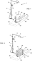
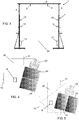
- load 24 means one or more pallets 30 on which the material and/or the payload 32 to be transported is placed (cf. fig. 1 ), or a pallet 30 alone, but also a stack of pallets 30 (cf. fig. 2 ), with or without material and/or the payload 32 to be transported.
- the apparatus 1 comprises upper detection means 8, which are positioned so as to frame a work area 20 of a carrier 22, which handles a load 24, from the top and are configured to acquire a plurality of images of the objects and of the framed scene from the top and to acquire the distance (depth) in real time between the detection means themselves and the framed objects or scene.
- These upper detection means 8 comprise one or more electronic devices for acquiring two-dimensional images in sequence and at least one sensor which provides its distance (depth) respect to the framed objects or scene, in real time.
- these detection means 8 output a series of two-dimensional images correlated with the depth information related to objects or to the scene captured in the corresponding image.
- a value is associated to each pixel of the acquired image which represents the corresponding distance (depth) which was detected and defines the gray intensity of the pixel, if the image is a grayscale image, or the fundamental color intensity of the pixel itself, if the image is a color image.
- the upper detection means 8 comprise depth cameras, i.e. of the type adapted to construct depth maps and operate according to known principles, e.g. time of flight TOF (cf. e.g. US 2011/0317005 and US 8711206 ), of the offset or stereoscopic triangulation type (cf. e.g. US 8740794 , US 8493496 and US 8150142 ).
- the means 8 may also comprise traditional cameras or optical sensors, i.e. not depth cameras or sensors, integrated with, and/or connected to appropriate depth sensors.
- the upper detection means 8 are positioned so as to frame the work area 20 from the top, and in particular are positioned over the maximum height of the load 24 which may pass underneath and/or by the side of it. More in detail, the upper detection means 8 are positioned at a height from the floor comprised between 2 and 4 meters. Appropriately, the upper detection means 8 face downwards so as to be able to frame the upper surface 31 of the transiting load 24.
- the upper detection means 8 may comprise a single image sensor (camera), preferably of the depth type, positioned over the load 24, however it is understood that such means may appropriately comprise even multiple cameras, in all cases always positioned over the load 24.
- the work area 20 may be a loading bay and/or a transit and passage route which may appropriately connect a source site 26 to a destination site 28.
- the transit route 20 may connect a container or a body of a truck to a warehouse or vice versa, or may connect two warehouses or even two different positions of the same warehouse to each other.
- the upper detection means 8 may be mounted on an existing structure or preferably may be mounted on a load-bearing structure 2 specifically provided for such an application.
- the load-bearing structure 2 may comprise a single upright 4 and only one crosspiece 6 (cf. fig. 1 and 2 ), or may comprise two uprights 4 joined by the upper end by a crosspiece 6 (cf. fig. 3 ).
- the load-bearing structure 2 may also only comprise an upright 4 or only two uprights 4, which mutually delimit the work area 20 for the load 24.
- the height of the uprights 4 is higher than the maximum height of the load 24, which must be handled in that particular installation and that the carrier 22 keeps lifted from the ground sufficiently to transport it.
- the upper detection means 8 may be fitted on the crosspiece 6 and/or on the top of at least one upright 4 of said load-bearing structure 2.
- the apparatus 1 also comprises side detection means 10 which are positioned so as to frame the work area 20 laterally.
- the side detection means 10 are configured to laterally acquire a plurality of images of the objects of the framed scene.
- the side detection means 10 comprise one or more image sensors (cameras), appropriately positioned at different heights and facing towards the work area 20.
- the side cameras 10 may be mounted either on the same upright 4 or on both uprights 4 of the load-bearing structure 2.
- the side detection means 10 are also configured to acquire the distance (depth) between the means themselves and the framed scene.
- the side detection means 10 may be of type described above for the upper detection means 8.
- the acquisition frequency of the images and of the depth data by the upper 8 and/or side 10 detection means may be predetermined by the operator or the installer and is related to the specific needs of the latter, e.g. in terms of image resolution and on the basis of the transit speed of the transport vectors 22, and of the specific features of the cameras used.
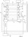
- the apparatus 1 also comprises a control and processing unit 12. More in detail, it comprises at least one processor, such a PC for example.
- the upper 8 and/or side 10 detection means may be connected to a single control and central processing unit 12 of the apparatus 1 or may be connected to a control and processing unit 12 of its own, to which the other detection means provided in the apparatus itself can also be connected.
- the detection means 8 and 10 installed on the other load-bearing structures 2 can be connected to the control and processing unit 12 of a first load-bearing structure 2, which load-bearing structures may be appropriately fitted at the different loading bays of a warehouse or also along the transit routes 20 of the carriers 22 within them.
- a software program 40 is loaded and run in the control and processing unit 12 and the depth data acquired by the upper 8 and/or the side 10 detection means.
- the software program 40 comprises a software module 50 for automatically identifying the presence of handling in the work area 20.
- the upper 8 and/or the side 10 detection means are always active and continuously acquire images of the scene at the work area 20.
- the captured images are transmitted to the module 50, which is configured to compare each of said images with a reference image 51 which frames the empty work area (e.g. free from carriers, people, loads etc.) in real time.
- a reference image 51 which frames the empty work area (e.g. free from carriers, people, loads etc.) in real time.
- the reference image is acquired and stored during the step of calibrating of the apparatus 1.
- the software module 50 stores the images captured by the upper 8 and/or the side 10 detection means, preferably in the unit 12 itself, so as to proceed with the subsequent processing thereof. On the contrary, if there are no differences between the acquired image and the reference image 51, such images are not stored.
- the apparatus 1 appropriately does not need a further external device (e.g. a photocell) to create a trigger signal to start the acquisition by the corresponding detection means 8 and/or 10.
- a further external device e.g. a photocell
- the acquired and stored images are analyzed in real time by a module 52 to detect the presence of one or more loads 24 to be analyzed.
- the module 52 is configured to discriminate whether the detected handling concerns a load 24, or also more loads 24, which must be analyzed or concerns a passage which must not be analyzed.
- the passage of people through the work area 20 is recognized by searching the dimensional and/or shape features proper of people (e.g. the head and the arms) in the acquired and stored images. Appropriately, recognizing people also facilitates determining the carriers 22, in which the operator can be seen by the cameras.
- the module 52 may use the images supplied also by only one of the detection means 8 and/or 10 provided in the apparatus 1.
- the most significant image is selected by using an appropriate criterion which is set on the basis of the type of information that is intended to be obtained from the image itself (e.g. related to the dimensions and/or volume of the load, or the number of pallets, etc.), as will be more apparent below.
- the software module 54 is configured for:
- the best score (i.e. the one closest to 1) is obtained the more the actual area of the load 59 approaches the area of the rectangle 61 circumscribing it (cf. fig. 7c ).
- the best score is obtained by the image which has the highest number of pixels which relate to the load and the value of which is set using the corresponding depth data. In particular, such an image is obtained when the load 24 passes under the upper detection means 8 or when it is centered with respect to the side detection means 10.
- the software module 54 can be configured not to analyze and not to associate any score 57 to the first and the last images of the acquired image set 55 (because they are the ones which correspond to the beginning or the end of the passage of the load through the work area 20) and/or to those in which the load 24 and/or the carrier 22 (cf. fig. 7a ) is not completely identified, using traditional image and pattern recognition processing techniques.
- the software program 40 also comprises a further segmentation module 56 configured to distinguish and/or isolate the areas of interest (and i.e. the areas concerning only the load 24) from the areas not of interest, such as those which relate to the carrier 22 and/or to people transiting through the work area in the selected image 58 or in the acquired and stored images 55.
- a further segmentation module 56 configured to distinguish and/or isolate the areas of interest (and i.e. the areas concerning only the load 24) from the areas not of interest, such as those which relate to the carrier 22 and/or to people transiting through the work area in the selected image 58 or in the acquired and stored images 55.
- the software segmentation module 56 may be run on all acquired and stored images 55, i.e. before the software module 54 for selecting the best image, and/or may be run downstream thereof, i.e. only on the selected image 58.
- the segmentation software module 56 may be configured to identify the carrier 22 in an image, e.g. by recognizing some constructive features of the carrier itself, such as for example the height of the resting plane of electric hand pallet trucks and their relative position with respect to the operator driving it.
- the segmentation software module 56 is configured to determine firstly the direction of advancement of the carrier and then to calculate its contours, the relative position set between the carrier 22 and the load 24 being equal.
- the segmentation software module 56 makes it possible to avoid the application of particular markers to the carrier 22 to separate it from the load 24 to be detected.
- a database 53 in which the distinctive features of the various types of carriers 22 are stored may be provided. So, during the step of processing of the acquired images, the module 56 may be configured to compare the acquired images with those stored in the database 53 in order to identify the carrier 22 to isolate the load 24, the dimensions and/or the volume of which are to be determined, and/or the presence and/or number of pallets 30 included in which are to be determined, therefrom.
- the information related to carriers 22, which is stored in the database 53 may be entered and/or updated during the passages of the carriers through the work area 20, with or without the load to be detected.
- This is particularly advantageous if there are multiple simultaneous passages of carriers 22 through the work area 20, e.g. in the case of a carrier 22 with a load 24 which enters into a container and at the same time a carrier 22 which exits from the container itself.
- the image itself may be sent to the software module 60 for determining its dimensions and/or volume.
- the software module 60 receives the image 58, which was selected by the module 54 from those acquired by the upper detection means 8 and in which the portion corresponding to the upper surface 31 of the load 24 was identified and appropriately isolated. Furthermore, the software module 60 also receives the depth data related to the selected image 58, which were acquired by the upper detection means 8 and correspond to the distance between them and the upper surface 31 of the load 24.
- the software module 60 is configured to process the selected image 58 and to identify the edges of the upper surface 31 of the load 24 in order to thus determine its dimensions (length and width), its perimeter and/or the area.
- the software module 60 uses the corresponding depth data of the selected image 58. In particular, on the basis of the depth data related to the distance between the upper surface 31 of the load 24 and the upper detection means 8, and the distance of such means 8 respect to the floor being known, the software module 60 determines the maximum height 33 of the load 24, which corresponds to the distance between the upper surface 31 of the load 24 and the floor.
- the software module 60 determines the maximum volume (dimension) of the load itself.
- the fact that the upper detection means 8 acquire an image of the load 24 from the top makes it possible to determine the volume of the load 24 also considering the possible overflow present in it.
- the software module 60 may be configured to divide the upper surface of the load 24, as it was identified in the selected image 58, into a plurality of subareas (of known width and length) so that the volume of the load 24 is calculated considering the heights of the single subareas.
- the corresponding volume is calculated for each subarea by using the depth data acquired by the upper detection means 8, with methods similar to those described above. Then, data representative of the actual volume of the load is obtained by adding up all the volumes of the subareas, and this is useful in particular if the load is not uniformly distributed at its upper surface 31.
- the height values of each subarea also make it possible to obtain the envelope of the upper surface of the load 24, and to determine the maximum, minimum and average height thereof.
- the images acquired by means of the side detection means 10 are also inputted to the software module 40 to be processed one by one by the software modules 50, 52, 54 and 56.
- the software module 54 appropriately selects the most significant image in manner substantially similar to that described above.
- the segmentation software module 56 is appropriately configured to identify and isolate the area of interest related to the load 24 in the images acquired by the side detection means 10 and/or in the one selected by the module 54.
- the side detection means 10 are positioned and configured so as to acquire the images of the side and/or front and/or rear surfaces of the load 24, from which it is thus possible to recognize the composition thereof and this in order to recognize whether the load comprises a single pallet 30 or a stack of pallets 30, and to recognize whether the load 24 is formed by multiple loaded pallets or multiple empty pallets or by multiple pallets which are partially loaded and partially empty.
- the image 67 (cf. fig. 8a ), which is selected by the software module 54 from those acquired by the side detection means 10, is inputted into a software module 70 to determine the presence and the number (count) of the pallets 30 which form the load 24.
- the software module 70 is configured to identify the pallets present in the image 67 in order to determine the number of pallets forming the load itself. More in detail, the number of pallets 30 forming the load 24 are counted by identifying the portions corresponding to the side openings 68 of the pallet in the selected image 67 and then calculating their dimensions 69 and/or their distance 65 (cf. fig. 8b ).
- the dimensions and distances between the side openings of pallets is fixed and known, and thus it is possible to identify the presence of one or more pallets 30 in the image itself by identifying the portions of substantially rectangular shape in the acquired laterally image 67 and by determining the dimensions 69 thereof as well as the distance 65.
- the image 67 which was acquired by the side detection means 10 and appropriately selected by the software module 54, may be inputted into a software module 72 which is configured to obtain the height 74 from the lower surface of the load 24 with respect to the floor on the basis of such an image.
- the height 74 thus calculated is sent to the software module 60 in order to improve the determination accuracy of the height and of the volume of the load 24, obtained only by using the images and the depth data acquired by means of the upper detection means 8.
- the actual height of the load may be appropriately determined by subtracting the height 74 of the lower surface of the load 24 from the floor from the maximum height 33.
- the carrier 22 is a fork-lift truck
- the load 24 is lifted from the ground by a height which varies from pallet to pallet, and thus the accuracy of the calculation of the two values is increased by determining and considering this type of offset in the total count of the height and volume of the load 24.
- the height 74 of the load respect to the floor may also be determined using alternative devices to the side detection means 10, such as for example a laser triangulation system or system with laser scanner.
- the software module 72 is also configured to determine the inclination 75 of the load 24 respect to its correct vertical arrangement on the basis of the image 67 selected from those acquired by the side detection means 10.
- the operator tends to incline the load itself backwards for safety reasons in order to prevent it from falling.
- the information concerning the inclination 75 of the load 24 thus determined is sent to the module 60 to be appropriately considered as offset for calculating and determining the actual height and volume of the load itself, thus increasing the calculation accuracy thereof.
- the direction of advancement of the carrier 22 with the load 24 should preferably form an angle substantially smaller than 30° with axis 21 of the work area 20 (cf. fig. 4 and 5 ).
- the apparatus 1 also makes it possible to determine the dimensions and/or the volume of at least two loads 24 which are transported by different carriers 22 and which cross the work area 20 at the same time even in different directions.
- the upper detection means 8 are arranged to acquire images, in which two loads 24 are represented, so as to calculate the corresponding dimensions and volume in the manner described above.
- each loading bay of a warehouse there could be a structure 2 with two uprights 4, 4' mutually distanced so as to allow the simultaneous passage of two carriers 22 in opposite directions under them, i.e. of a carrier 22 advancing towards a truck or a container to load it and other empty carrier 22 which exits from the truck or container after having loaded it.
- the pallets 30 are counted by using the images acquired by the side detection means 10 installed on the upright 4, near which the carriers 22 pass with the respective loads.
- the carriers 22 with the respective loads may pass near both uprights 4, 4' of the structure 2.
- the apparatus 1 makes it possible to easily determine the dimensions and/or volume of at least two loads arranged side-by-side which are transported by a single carrier 22 (cf. fig. 4 e 5).
- the upper detection means 8 are arranged to acquire images in which both loads 24, are represented in order to calculate the corresponding dimensions and the corresponding volumes according to the methods described above in this manner.
- the software 40 identifies the separation zone between the two loads in the image itself and determines the perimeter of the single load by searching the contours. The previously described operations are subsequently performed to determine the height and the volume.
- the software 40 may also comprise a software module 76 configured to obtain a planarity index of the upper surface of the pallet 30 from the images and/or data acquired by the upper detection means 8.
- the planarity is determined by analyzing the height variation of the upper surface 31 of the load 24 on the basis of depth information acquired by means of the upper detection means 8. More in detail, the height variations are analyzed by comparing the height values of the micro areas in which the upper surface 31 of the load is divided. Such information makes it possible to establish whether further pallets 30 can be appropriately superimposed over the upper surface of the load 24 in order to optimize the number of pallets to be loaded on a same carrier 22.
- the software program 40 loaded and run by the control unit 12 can output one or more of the following parameters:
- the apparatus 1 is modular and includes the possibility of using one or more additional high-resolution cameras and/or an appropriate software module in order to recognize the pallet type starting from the acquired images, e.g. in order to discriminate whether the load comprises an EPAL type pallet or a disposable pallet.
- the type of pallet 30 may be recognized by identifying the specific brand that distinguishes it (EPAL, UIC, etc.) by means of pattern match or optical character recognition (OCR) algorithms.
- the software program 40 is configured to process the depth data acquired by the detection means 8 and 10 separately from the corresponding images acquired thereby, so that the subsequent processing of the two-dimensional images, e.g. aimed at detecting the edges of the objects present, do not cause any distortion of the depth data; however, the association is always maintained between each image and the corresponding depth data in order to use it appropriately as described above in the module 60 for determining the dimensions and/or the volume of the load 24.
- the software modules 40 in order to recognize the load 24, and/or the carrier 22 and/or the operators and/or possible other objects or parts thereof, use traditional image processing techniques and algorithms, such as for example pattern match algorithms for recognizing the objects by determining some particular features thereof by means of appropriate artificial intelligence algorithms (machine learning, artificial intelligence, neutral networks, etc.).
- the apparatus 1 may comprise a display, not shown, to view the parameter values output by the software 40.
- the software 40 loaded on the central and processing unit 12 can interface or be integrated in the enterprise resource planning program 90 so as to allow the information output by the software 40 to be immediately used.
- the software 40 can be also configured to associate a univocal identification code to each single load 24, of which an image was acquired by means of the upper 8 and/or the side 10 detection means and of which the dimensions, volume and/or other information were determined.
- the operator can read the barcode associated to the load 24 before it enters into the work area 20 by means of an appropriate instrument; the read code is then transferred to the control and processing unit 12, which is associated thus to the data calculated and determined by the software program itself by means of the software program 40; appropriately when all the loads of the same shipment have been measured, the processing and control unit 12 sends all the results associated to the corresponding codes to the enterprise resource planning program 90.
- the association between barcodes and performed measurements may be performed by the enterprise resource planning program 90 present in the facility.
- the barcode may be read by means of a traditional manual reader or automatically by means of RFID or by means of cameras configured to automatically recognize the characters of the code applied to the load (obviously, the barcode must be positioned on the visible side of the load in this case).
Landscapes
- Physics & Mathematics (AREA)
- General Physics & Mathematics (AREA)
- Length Measuring Devices By Optical Means (AREA)
- Manipulator (AREA)
Claims (15)
- Vorrichtung (1) zum Bestimmen der Abmessungen von mindestens einer Last (24), die sich mittels eines Trägers (22) über einen Arbeitsbereich (20) hinweg bewegt, vorzugsweise von mindestens einer Last (24), die mindestens eine Palette (30) umfasst, die durch einen Träger (22) über den Arbeitsbereich (20) hinweg befördert wird, die Abmessungen umfassend Länge und Breite der Last (24) und die maximale Höhe (33) der Last (24), die dem Abstand zwischen der Oberseite (31) der Last (24) und dem Boden entspricht, dadurch gekennzeichnet, dass sie umfasst:- obere Detektionsmittel (8), die angeordnet sind, um den Arbeitsbereich (20) von oben einzurahmen, und die dazu ausgelegt sind, eine Sequenz von Bildern (55) der eingerahmten Szene von oben zu erfassen und um Tiefendaten der in der eingerahmten Szene vorhandenen Elemente zu erfassen, wobei die oberen Detektionsmittel (8) höher als die maximale vorhersehbare Höhe der Last, die durch den Träger (22) befördert wird, angeordnet sind und dazu ausgelegt sind, eine Vielzahl von Bildern von oben zu erfassen, in denen mindestens die Oberseite (31) der Last (24) dargestellt ist, und den Abstand zwischen den Mitteln selbst und der Oberseite (31) der Last (24) in Echtzeit zu erfassen, wobei die oberen Detektionsmittel (8) mindestens einen Bild- und einen Tiefensensor umfassen,- mindestens eine Steuer- und Verarbeitungseinheit (12), die mit den oberen Detektionsmitteln (8) verbunden ist und in der ein Softwareprogramm (40) geladen ist, ausgelegt zum:und ferner dadurch gekennzeichnet, dass das Softwareprogramm (40):- Auswählen von mindestens einem signifikanten Bild (58) zum Zweck des Bestimmens der Abmessungen der Last (24) aus der Sequenz von Bildern (55) der eingerahmten Szene, die durch die Detektionsmittel (8) erfasst wurden,- Identifizieren des Abschnitts, der der Oberseite (31) der Last (24) in dem so ausgewählten Bild (58) entspricht,- Bestimmen der Länge und der Breite der Last (24) auf Basis der Länge und der Breite der Kanten der Oberseite (31) der Last (24), die in dem so identifizierten Abschnitt detektiert wurde, und Bestimmen der maximalen Höhe der Last (24) auf Basis der Tiefendaten in Verbindung mit dem ausgewählten Bild (58) und in Bezug auf den Abstand zwischen der Oberseite (31) der Last (24) und den oberen Detektionsmitteln (8) und auf Basis des bekannten Abstands dieser Mittel (8) bezogen auf den Boden,- ein Segmentierungssoftwaremodul (56) umfasst, das dazu ausgelegt ist, den Abschnitt zu erkennen, der der Last (24) in dem ausgewählten Bild (58) oder allen Bildern (55), die durch die Detektionsmittel (8) erfasst werden, entspricht, wobei das Segmentierungssoftwaremodul (56) dazu ausgelegt ist, in dem ausgewählten Bild (58) oder allen Bildern (55), die durch die Detektionsmittel (8) erfasst werden, den Abschnitt des Bilds in Bezug auf den Träger (22) zu erkennen, um ihn von dem Abschnitt in Bezug auf die Last (24) zu trennen.
- Vorrichtung nach einem oder mehreren der vorhergehenden Ansprüche, dadurch gekennzeichnet, dass das Softwareprogramm (40) dazu ausgelegt ist, den Umfang und die Fläche der Oberseite der Last (24) auf Basis der Länge und der Breite des so identifizierten Abschnitts zu bestimmen.
- Vorrichtung nach einem oder mehreren der vorhergehenden Ansprüche, dadurch gekennzeichnet, dass das Softwareprogramm (40) außerdem dazu ausgelegt ist, das Volumen der Last (24) durch Verwenden der zuvor bestimmten Fläche und der Höhe der Oberseite der Last (24) zu bestimmen.
- Vorrichtung nach einem oder mehreren der vorhergehenden Ansprüche, dadurch gekennzeichnet, dass das Softwareprogramm (40) ein Softwaremodul (60) umfasst, das ausgelegt ist zum:- Teilen der Oberseite der Last (24), wie sie in dem ausgewählten Bild (58) identifiziert wurde, in eine Vielzahl von Teilbereichen von bekannten Abmessungen,- Berechnen des Volumens der Last unter jedem Teilbereich durch Verwenden der entsprechenden Tiefendaten in Verbindung mit dem ausgewählten Bild (58) und- Integrieren des Volumens jedes so berechneten Teilbereichs, um das tatsächliche Volumen der Last (24) zu erhalten.
- Vorrichtung nach einem oder mehreren der vorhergehenden Ansprüche, dadurch gekennzeichnet, dass das Softwareprogramm (40) ein Softwaremodul (60) umfasst, das ausgelegt ist zum:- Teilen der Oberseite der Last (24), wie sie in dem ausgewählten Bild (58) identifiziert wurde, in eine Vielzahl von Teilbereichen von bekannten Abmessungen,- Bestimmen der maximalen, minimalen und/oder durchschnittlichen Höhe der Last (24) und/oder der Hülle der Oberseite (31) der Last selbst auf Basis des entsprechenden Tiefenbereichs in Verbindung mit dem ausgewählten Bild (58) und bezogen auf jeden der Teilbereiche.
- Vorrichtung nach einem oder mehreren der vorhergehenden Ansprüche, dadurch gekennzeichnet, dass sie seitliche Detektionsmittel (10) umfasst, die angeordnet sind, um den Arbeitsbereich (20) seitlich einzurahmen, um eine Sequenz von Bildern der Seitenoberflächen der sich bewegenden Last (24) zu erfassen, wobei die mindestens eine Steuer- und Verarbeitungseinheit (12) mit den seitlichen Detektionsmitteln (10) verbunden ist.
- Vorrichtung nach einem oder mehreren der vorhergehenden Ansprüche, dadurch gekennzeichnet, dass sie eine lasttragende Struktur (2) umfasst, an der die oberen Detektionsmittel (8) installiert sind, die lasttragende Struktur (2) umfassend:- mindestens einen Ständer (4), der an dem Arbeitsbereich (20) angeordnet ist, oder- einen Ständer (4), der an dem Arbeitsbereich (20) angeordnet ist, und ein Querstück (6), das an der Oberseite des Ständers (4) verbunden ist, oder- ein Querstück (6), das an der Oberseite mit zwei Ständern (4) verbunden ist, die miteinander den Arbeitsbereich (20) begrenzen und die vorzugsweise durch das Querstück (6) zusammengefügt sind.
- Vorrichtung nach Anspruch 6, dadurch gekennzeichnet, dass zum Bestimmen des Vorhandenseins und/oder der Anzahl von Paletten (30), die die mindestens eine Last (24) bilden, die durch den Träger (22) über den Arbeitsbereich (20) hinweg befördert wird, das Softwareprogramm (40) dadurch gekennzeichnet ist, dass es auch ausgelegt ist zum:- Auswählen von mindestens einem Bild (67), das das signifikanteste für die Zwecke des Bestimmens des Vorhandenseins und/oder der Anzahl von Paletten (30) der Last (24) ist, aus der Sequenz von Bildern, die durch die seitlichen Detektionsmittel (10) erfasst werden,- Bestimmen des Vorhandenseins und/oder der Anzahl von Paletten (30), die die Last (24) bilden, durch Identifizieren der Abschnitte, die den in jeder Palette (30) bereitgestellten Seitenöffnungen entsprechen, in dem so ausgewählten Bild (58).
- Vorrichtung nach einem oder mehreren der vorhergehenden Ansprüche, dadurch gekennzeichnet, dass das Softwareprogramm (40) ein Softwaremodul (50) zum automatischen Identifizieren des Vorhandenseins einer Bewegung in dem Arbeitsbereich (20) auf Basis der durch die oberen Mittel (8) durchgeführten Erfassungen umfasst.
- Vorrichtung nach einem oder mehreren der vorhergehenden Ansprüche, dadurch gekennzeichnet, dass das Softwaremodul (50) die Sequenz von Bildern, die durch die oberen Detektionsmittel (8) erfasst werden, empfängt und dazu ausgelegt ist, in Echtzeit jedes der Bilder mit einem Referenzbild (51), das den leeren Arbeitsbereich einrahmt, zu vergleichen und die Bilder, die durch die oberen Detektionsmittel (8) erfasst werden, zu speichern, wenn der Unterschied zwischen den verglichenen Bildern einen vorgegebenen Schwellenwert überschreitet.
- Vorrichtung nach einem oder mehreren der vorhergehenden Ansprüche, dadurch gekennzeichnet, dass das Softwareprogramm (40) ein Softwaremodul (52) umfasst, das dazu ausgelegt ist, das Vorhandensein von einer oder mehreren zu analysierenden Lasten (24) und das Vorhandensein von einem oder mehreren Trägern (22) und Bedienern in dem ausgewählten Bild (58) oder allen Bildern, die durch die Detektionsmittel (8 und/oder 10) erfasst werden, zu erkennen.
- Vorrichtung nach einem oder mehreren der vorhergehenden Ansprüche, dadurch gekennzeichnet, dass zum Auswählen eines einzelnen Bilds aus der Sequenz von Bildern der eingerahmten Szene, die durch die Detektionsmittel (8 und/oder 10) erfasst wurden, eines einzelnen Bilds, das das signifikanteste für die Zwecke des Bestimmens der Abmessungen und/oder des Volumens von mindestens einer Last (24) und/oder für die Zwecke des Bestimmens der Anzahl von Paletten der Last (24) ist, das Softwareprogramm (40) ein Softwaremodul (54) umfasst, das ausgelegt ist zum:- Analysieren aller Bilder (55), die während des Durchgangs der Last (24) erfasst und gespeichert wurden, um automatisch jedem Bild eine Bewertung, die für die Anzeigequalität der Last (24) in jedem Bild repräsentativ ist, zuzuordnen,- Auswählen des Bilds (58), das die beste Bewertung aufweist, aus allen Bildern (55).
- Vorrichtung nach einem oder mehreren der vorhergehenden Ansprüche, dadurch gekennzeichnet, dass das Softwareprogramm (40) ein Softwaremodul (72) umfasst, das dazu ausgelegt ist, die Höhe (74) der Unterseite der Last (24) vom Boden und/oder die Neigung (75) der Last in Bezug auf ihre korrekte vertikale Anordnung auf Basis von mindestens einem Bild, das durch die seitlichen Detektionsmittel (10) erhalten wird, zu erhalten, und dadurch, dass das Softwaremodul (60) dazu ausgelegt ist, die tatsächliche Höhe der Last (24) unter Verwendung der Höhendaten (74) der Unterseite der Last (24) vom Boden und/oder der Neigungsdaten (75) der Last in Bezug auf ihre entsprechende vertikale Anordnung zu bestimmen, wobei die Daten durch das Softwaremodul (72) bestimmt werden.
- Vorrichtung nach einem oder mehreren der vorhergehenden Ansprüche, dadurch gekennzeichnet, dass das Softwareprogramm (40) ein Softwaremodul (76) umfasst, das dazu ausgelegt ist, einen Ebenflächigkeitsindex der Oberseite (31) der Last (24) durch Verwenden der Bilder und/oder der Tiefendaten, die die Oberfläche selbst betreffen und die durch die oberen Detektionsmittel (8) erfasst wurden, zu bestimmen.
- Vorrichtung nach einem oder mehreren der vorhergehenden Ansprüche, dadurch gekennzeichnet, dass sie Mittel umfasst, die dazu ausgelegt sind, beginnend ab einem oder mehreren der erfassten Bilder, den Typ der Palette oder Paletten (30), die in der Last (24) vorhanden sind, zu erkennen und/oder die Oberflächenzustände davon zu verifizieren.
Applications Claiming Priority (2)
| Application Number | Priority Date | Filing Date | Title |
|---|---|---|---|
| ITUB2015A003553A ITUB20153553A1 (it) | 2015-09-11 | 2015-09-11 | Metodo ed apparecchiatura di rilevamento di pallet in movimento. |
| PCT/IB2016/055416 WO2017042747A2 (en) | 2015-09-11 | 2016-09-12 | An apparatus for the determination of the features of at least a moving load |
Publications (2)
| Publication Number | Publication Date |
|---|---|
| EP3347672A2 EP3347672A2 (de) | 2018-07-18 |
| EP3347672B1 true EP3347672B1 (de) | 2020-04-22 |
Family
ID=54843990
Family Applications (1)
| Application Number | Title | Priority Date | Filing Date |
|---|---|---|---|
| EP16794726.6A Active EP3347672B1 (de) | 2015-09-11 | 2016-09-12 | Vorrichtung zur bestimmung der merkmale von mindestens einer beweglichen last |
Country Status (3)
| Country | Link |
|---|---|
| EP (1) | EP3347672B1 (de) |
| IT (1) | ITUB20153553A1 (de) |
| WO (1) | WO2017042747A2 (de) |
Families Citing this family (7)
| Publication number | Priority date | Publication date | Assignee | Title |
|---|---|---|---|---|
| US11475554B2 (en) * | 2017-09-01 | 2022-10-18 | Ball Coporation | Finished pallet inspection apparatus |
| SE1751405A1 (en) * | 2017-11-14 | 2019-04-02 | Cind Ab | Method and image processing system for facilitating estimation of volumes of load of a truck |
| ES2939386T3 (es) * | 2018-05-21 | 2023-04-21 | Automatizacion Y Sist De Inspeccion En Linea Global S L | Dispositivo y método para la clasificación de contenedores |
| PL3572767T3 (pl) * | 2018-05-25 | 2021-08-02 | Mettler-Toledo Gmbh | Dynamiczne wymiarowanie palety – tarowanie wózka widłowego |
| US11379788B1 (en) | 2018-10-09 | 2022-07-05 | Fida, Llc | Multilayered method and apparatus to facilitate the accurate calculation of freight density, area, and classification and provide recommendations to optimize shipping efficiency |
| JP6798725B1 (ja) * | 2019-11-14 | 2020-12-09 | Necプラットフォームズ株式会社 | 荷物計測装置、荷物受付システム、荷物計測方法、及びプログラム |
| CN114674263B (zh) * | 2022-05-27 | 2022-09-23 | 深圳市海清视讯科技有限公司 | 体积测量方法、装置、设备及可读存储介质 |
Family Cites Families (6)
| Publication number | Priority date | Publication date | Assignee | Title |
|---|---|---|---|---|
| US7757946B2 (en) * | 2004-04-16 | 2010-07-20 | Acme Scale Company, Inc. | Material transport in-motion product dimensioning system and method |
| US20080035390A1 (en) * | 2006-08-09 | 2008-02-14 | Wurz David A | Dimensioning and weighing system |
| EP2439487B1 (de) * | 2010-10-06 | 2012-08-22 | Sick Ag | Volumenmessvorrichtung für bewegte Objekte |
| IT1404187B1 (it) * | 2011-02-28 | 2013-11-15 | Datalogic Automation Srl | Metodo per l'identificazione ottica di oggetti in movimento |
| WO2012155104A1 (en) * | 2011-05-11 | 2012-11-15 | Proiam, Llc | Enrollment apparatus, system, and method featuring three dimensional camera |
| DE102014011821A1 (de) * | 2014-08-08 | 2016-02-11 | Cargometer Gmbh | Vorrichtung und Verfahren zur Volumenbestimmung eines durch ein Flurförderzeug bewegten Objekts |
-
2015
- 2015-09-11 IT ITUB2015A003553A patent/ITUB20153553A1/it unknown
-
2016
- 2016-09-12 EP EP16794726.6A patent/EP3347672B1/de active Active
- 2016-09-12 WO PCT/IB2016/055416 patent/WO2017042747A2/en active Application Filing
Non-Patent Citations (1)
| Title |
|---|
| None * |
Also Published As
| Publication number | Publication date |
|---|---|
| EP3347672A2 (de) | 2018-07-18 |
| ITUB20153553A1 (it) | 2017-03-11 |
| WO2017042747A2 (en) | 2017-03-16 |
| WO2017042747A3 (en) | 2017-04-27 |
Similar Documents
| Publication | Publication Date | Title |
|---|---|---|
| EP3347672B1 (de) | Vorrichtung zur bestimmung der merkmale von mindestens einer beweglichen last | |
| US9880269B2 (en) | Apparatus and methods for dimensioning an object carried by a vehicle moving in a field of measurement | |
| AU2021200584B2 (en) | Automated storage and retrieval system with detector for detecting items extending beyond dimensional threshold | |
| US10290115B2 (en) | Device and method for determining the volume of an object moved by an industrial truck | |
| US10776661B2 (en) | Methods, systems and apparatus for segmenting and dimensioning objects | |
| EP2439487B1 (de) | Volumenmessvorrichtung für bewegte Objekte | |
| US8561897B2 (en) | Load tracking utilizing load identifying indicia and spatial discrimination | |
| US8463079B2 (en) | Method and apparatus for geometrical measurement using an optical device such as a barcode and/or RFID scanner | |
| US20180143003A1 (en) | Dimensioning system for, and method of, dimensioning freight in motion along an unconstrained path in a venue | |
| US9898833B1 (en) | Apparatus and method for determining the dimensions of a package while in motion | |
| US20220138674A1 (en) | System and method for associating products and product labels | |
| CN108629659B (zh) | 利用视觉测量进行盘点的无人售货系统 | |
| CA2786407A1 (en) | Method and system for sensing the position of a vehicle | |
| CN114253253A (zh) | 一种基于人工智能的目标识别方法、装置及机器人 | |
| KR100439178B1 (ko) | 3차원 물체 치수 측정 시스템 및 방법 | |
| CN111386533A (zh) | 使用对称定位的空白区域检测和识别图像数据中图形字符表示的方法和装置 | |
| CN213301104U (zh) | 一种尺寸检测系统 | |
| US20240127471A1 (en) | Information processing apparatus, information processing system, information processing method, and recording medium |
Legal Events
| Date | Code | Title | Description |
|---|---|---|---|
| STAA | Information on the status of an ep patent application or granted ep patent |
Free format text: STATUS: UNKNOWN |
|
| STAA | Information on the status of an ep patent application or granted ep patent |
Free format text: STATUS: THE INTERNATIONAL PUBLICATION HAS BEEN MADE |
|
| PUAI | Public reference made under article 153(3) epc to a published international application that has entered the european phase |
Free format text: ORIGINAL CODE: 0009012 |
|
| STAA | Information on the status of an ep patent application or granted ep patent |
Free format text: STATUS: REQUEST FOR EXAMINATION WAS MADE |
|
| 17P | Request for examination filed |
Effective date: 20180409 |
|
| AK | Designated contracting states |
Kind code of ref document: A2 Designated state(s): AL AT BE BG CH CY CZ DE DK EE ES FI FR GB GR HR HU IE IS IT LI LT LU LV MC MK MT NL NO PL PT RO RS SE SI SK SM TR |
|
| AX | Request for extension of the european patent |
Extension state: BA ME |
|
| DAV | Request for validation of the european patent (deleted) | ||
| DAX | Request for extension of the european patent (deleted) | ||
| STAA | Information on the status of an ep patent application or granted ep patent |
Free format text: STATUS: EXAMINATION IS IN PROGRESS |
|
| 17Q | First examination report despatched |
Effective date: 20190503 |
|
| GRAP | Despatch of communication of intention to grant a patent |
Free format text: ORIGINAL CODE: EPIDOSNIGR1 |
|
| STAA | Information on the status of an ep patent application or granted ep patent |
Free format text: STATUS: GRANT OF PATENT IS INTENDED |
|
| INTG | Intention to grant announced |
Effective date: 20191119 |
|
| GRAS | Grant fee paid |
Free format text: ORIGINAL CODE: EPIDOSNIGR3 |
|
| GRAA | (expected) grant |
Free format text: ORIGINAL CODE: 0009210 |
|
| STAA | Information on the status of an ep patent application or granted ep patent |
Free format text: STATUS: THE PATENT HAS BEEN GRANTED |
|
| AK | Designated contracting states |
Kind code of ref document: B1 Designated state(s): AL AT BE BG CH CY CZ DE DK EE ES FI FR GB GR HR HU IE IS IT LI LT LU LV MC MK MT NL NO PL PT RO RS SE SI SK SM TR |
|
| REG | Reference to a national code |
Ref country code: CH Ref legal event code: EP |
|
| REG | Reference to a national code |
Ref country code: IE Ref legal event code: FG4D |
|
| REG | Reference to a national code |
Ref country code: DE Ref legal event code: R096 Ref document number: 602016034676 Country of ref document: DE |
|
| REG | Reference to a national code |
Ref country code: AT Ref legal event code: REF Ref document number: 1260696 Country of ref document: AT Kind code of ref document: T Effective date: 20200515 |
|
| REG | Reference to a national code |
Ref country code: SE Ref legal event code: TRGR |
|
| REG | Reference to a national code |
Ref country code: NL Ref legal event code: FP |
|
| REG | Reference to a national code |
Ref country code: LT Ref legal event code: MG4D |
|
| PG25 | Lapsed in a contracting state [announced via postgrant information from national office to epo] |
Ref country code: GR Free format text: LAPSE BECAUSE OF FAILURE TO SUBMIT A TRANSLATION OF THE DESCRIPTION OR TO PAY THE FEE WITHIN THE PRESCRIBED TIME-LIMIT Effective date: 20200723 Ref country code: NO Free format text: LAPSE BECAUSE OF FAILURE TO SUBMIT A TRANSLATION OF THE DESCRIPTION OR TO PAY THE FEE WITHIN THE PRESCRIBED TIME-LIMIT Effective date: 20200722 Ref country code: IS Free format text: LAPSE BECAUSE OF FAILURE TO SUBMIT A TRANSLATION OF THE DESCRIPTION OR TO PAY THE FEE WITHIN THE PRESCRIBED TIME-LIMIT Effective date: 20200822 Ref country code: LT Free format text: LAPSE BECAUSE OF FAILURE TO SUBMIT A TRANSLATION OF THE DESCRIPTION OR TO PAY THE FEE WITHIN THE PRESCRIBED TIME-LIMIT Effective date: 20200422 Ref country code: FI Free format text: LAPSE BECAUSE OF FAILURE TO SUBMIT A TRANSLATION OF THE DESCRIPTION OR TO PAY THE FEE WITHIN THE PRESCRIBED TIME-LIMIT Effective date: 20200422 Ref country code: PT Free format text: LAPSE BECAUSE OF FAILURE TO SUBMIT A TRANSLATION OF THE DESCRIPTION OR TO PAY THE FEE WITHIN THE PRESCRIBED TIME-LIMIT Effective date: 20200824 |
|
| PG25 | Lapsed in a contracting state [announced via postgrant information from national office to epo] |
Ref country code: LV Free format text: LAPSE BECAUSE OF FAILURE TO SUBMIT A TRANSLATION OF THE DESCRIPTION OR TO PAY THE FEE WITHIN THE PRESCRIBED TIME-LIMIT Effective date: 20200422 Ref country code: RS Free format text: LAPSE BECAUSE OF FAILURE TO SUBMIT A TRANSLATION OF THE DESCRIPTION OR TO PAY THE FEE WITHIN THE PRESCRIBED TIME-LIMIT Effective date: 20200422 Ref country code: HR Free format text: LAPSE BECAUSE OF FAILURE TO SUBMIT A TRANSLATION OF THE DESCRIPTION OR TO PAY THE FEE WITHIN THE PRESCRIBED TIME-LIMIT Effective date: 20200422 Ref country code: BG Free format text: LAPSE BECAUSE OF FAILURE TO SUBMIT A TRANSLATION OF THE DESCRIPTION OR TO PAY THE FEE WITHIN THE PRESCRIBED TIME-LIMIT Effective date: 20200722 |
|
| PG25 | Lapsed in a contracting state [announced via postgrant information from national office to epo] |
Ref country code: AL Free format text: LAPSE BECAUSE OF FAILURE TO SUBMIT A TRANSLATION OF THE DESCRIPTION OR TO PAY THE FEE WITHIN THE PRESCRIBED TIME-LIMIT Effective date: 20200422 |
|
| REG | Reference to a national code |
Ref country code: DE Ref legal event code: R097 Ref document number: 602016034676 Country of ref document: DE |
|
| PG25 | Lapsed in a contracting state [announced via postgrant information from national office to epo] |
Ref country code: ES Free format text: LAPSE BECAUSE OF FAILURE TO SUBMIT A TRANSLATION OF THE DESCRIPTION OR TO PAY THE FEE WITHIN THE PRESCRIBED TIME-LIMIT Effective date: 20200422 Ref country code: CZ Free format text: LAPSE BECAUSE OF FAILURE TO SUBMIT A TRANSLATION OF THE DESCRIPTION OR TO PAY THE FEE WITHIN THE PRESCRIBED TIME-LIMIT Effective date: 20200422 Ref country code: RO Free format text: LAPSE BECAUSE OF FAILURE TO SUBMIT A TRANSLATION OF THE DESCRIPTION OR TO PAY THE FEE WITHIN THE PRESCRIBED TIME-LIMIT Effective date: 20200422 Ref country code: DK Free format text: LAPSE BECAUSE OF FAILURE TO SUBMIT A TRANSLATION OF THE DESCRIPTION OR TO PAY THE FEE WITHIN THE PRESCRIBED TIME-LIMIT Effective date: 20200422 Ref country code: EE Free format text: LAPSE BECAUSE OF FAILURE TO SUBMIT A TRANSLATION OF THE DESCRIPTION OR TO PAY THE FEE WITHIN THE PRESCRIBED TIME-LIMIT Effective date: 20200422 Ref country code: SM Free format text: LAPSE BECAUSE OF FAILURE TO SUBMIT A TRANSLATION OF THE DESCRIPTION OR TO PAY THE FEE WITHIN THE PRESCRIBED TIME-LIMIT Effective date: 20200422 |
|
| PG25 | Lapsed in a contracting state [announced via postgrant information from national office to epo] |
Ref country code: SK Free format text: LAPSE BECAUSE OF FAILURE TO SUBMIT A TRANSLATION OF THE DESCRIPTION OR TO PAY THE FEE WITHIN THE PRESCRIBED TIME-LIMIT Effective date: 20200422 Ref country code: PL Free format text: LAPSE BECAUSE OF FAILURE TO SUBMIT A TRANSLATION OF THE DESCRIPTION OR TO PAY THE FEE WITHIN THE PRESCRIBED TIME-LIMIT Effective date: 20200422 |
|
| PLBE | No opposition filed within time limit |
Free format text: ORIGINAL CODE: 0009261 |
|
| STAA | Information on the status of an ep patent application or granted ep patent |
Free format text: STATUS: NO OPPOSITION FILED WITHIN TIME LIMIT |
|
| 26N | No opposition filed |
Effective date: 20210125 |
|
| REG | Reference to a national code |
Ref country code: CH Ref legal event code: PL |
|
| PG25 | Lapsed in a contracting state [announced via postgrant information from national office to epo] |
Ref country code: SI Free format text: LAPSE BECAUSE OF FAILURE TO SUBMIT A TRANSLATION OF THE DESCRIPTION OR TO PAY THE FEE WITHIN THE PRESCRIBED TIME-LIMIT Effective date: 20200422 |
|
| PG25 | Lapsed in a contracting state [announced via postgrant information from national office to epo] |
Ref country code: LU Free format text: LAPSE BECAUSE OF NON-PAYMENT OF DUE FEES Effective date: 20200912 |
|
| PG25 | Lapsed in a contracting state [announced via postgrant information from national office to epo] |
Ref country code: IE Free format text: LAPSE BECAUSE OF NON-PAYMENT OF DUE FEES Effective date: 20200912 Ref country code: LI Free format text: LAPSE BECAUSE OF NON-PAYMENT OF DUE FEES Effective date: 20200930 Ref country code: CH Free format text: LAPSE BECAUSE OF NON-PAYMENT OF DUE FEES Effective date: 20200930 |
|
| PGFP | Annual fee paid to national office [announced via postgrant information from national office to epo] |
Ref country code: BE Payment date: 20210803 Year of fee payment: 6 |
|
| PG25 | Lapsed in a contracting state [announced via postgrant information from national office to epo] |
Ref country code: TR Free format text: LAPSE BECAUSE OF FAILURE TO SUBMIT A TRANSLATION OF THE DESCRIPTION OR TO PAY THE FEE WITHIN THE PRESCRIBED TIME-LIMIT Effective date: 20200422 Ref country code: MT Free format text: LAPSE BECAUSE OF FAILURE TO SUBMIT A TRANSLATION OF THE DESCRIPTION OR TO PAY THE FEE WITHIN THE PRESCRIBED TIME-LIMIT Effective date: 20200422 Ref country code: CY Free format text: LAPSE BECAUSE OF FAILURE TO SUBMIT A TRANSLATION OF THE DESCRIPTION OR TO PAY THE FEE WITHIN THE PRESCRIBED TIME-LIMIT Effective date: 20200422 |
|
| PG25 | Lapsed in a contracting state [announced via postgrant information from national office to epo] |
Ref country code: MK Free format text: LAPSE BECAUSE OF FAILURE TO SUBMIT A TRANSLATION OF THE DESCRIPTION OR TO PAY THE FEE WITHIN THE PRESCRIBED TIME-LIMIT Effective date: 20200422 Ref country code: MC Free format text: LAPSE BECAUSE OF FAILURE TO SUBMIT A TRANSLATION OF THE DESCRIPTION OR TO PAY THE FEE WITHIN THE PRESCRIBED TIME-LIMIT Effective date: 20200422 |
|
| REG | Reference to a national code |
Ref country code: AT Ref legal event code: UEP Ref document number: 1260696 Country of ref document: AT Kind code of ref document: T Effective date: 20200422 |
|
| REG | Reference to a national code |
Ref country code: BE Ref legal event code: MM Effective date: 20220930 |
|
| P01 | Opt-out of the competence of the unified patent court (upc) registered |
Effective date: 20230517 |
|
| PG25 | Lapsed in a contracting state [announced via postgrant information from national office to epo] |
Ref country code: BE Free format text: LAPSE BECAUSE OF NON-PAYMENT OF DUE FEES Effective date: 20220930 |
|
| PGFP | Annual fee paid to national office [announced via postgrant information from national office to epo] |
Ref country code: NL Payment date: 20230920 Year of fee payment: 8 Ref country code: IT Payment date: 20230911 Year of fee payment: 8 Ref country code: GB Payment date: 20230911 Year of fee payment: 8 Ref country code: AT Payment date: 20230920 Year of fee payment: 8 |
|
| PGFP | Annual fee paid to national office [announced via postgrant information from national office to epo] |
Ref country code: SE Payment date: 20230911 Year of fee payment: 8 Ref country code: FR Payment date: 20230911 Year of fee payment: 8 Ref country code: DE Payment date: 20230920 Year of fee payment: 8 |
|
| REG | Reference to a national code |
Ref country code: BE Ref legal event code: NE Effective date: 20231117 |