EP3347182B1 - Appareil et procédé pour produire un objet tridimensionnel biocompatible - Google Patents
Appareil et procédé pour produire un objet tridimensionnel biocompatible Download PDFInfo
- Publication number
- EP3347182B1 EP3347182B1 EP16794721.7A EP16794721A EP3347182B1 EP 3347182 B1 EP3347182 B1 EP 3347182B1 EP 16794721 A EP16794721 A EP 16794721A EP 3347182 B1 EP3347182 B1 EP 3347182B1
- Authority
- EP
- European Patent Office
- Prior art keywords
- mold
- suction
- fluid substance
- biocompatible
- biocompatible fluid
- Prior art date
- Legal status (The legal status is an assumption and is not a legal conclusion. Google has not performed a legal analysis and makes no representation as to the accuracy of the status listed.)
- Active
Links
- 238000004519 manufacturing process Methods 0.000 title description 17
- 239000000126 substance Substances 0.000 claims description 70
- 210000003709 heart valve Anatomy 0.000 claims description 67
- 239000012530 fluid Substances 0.000 claims description 63
- 238000000034 method Methods 0.000 claims description 45
- 238000007664 blowing Methods 0.000 claims description 31
- 239000011247 coating layer Substances 0.000 claims description 19
- 239000002245 particle Substances 0.000 claims description 18
- 239000011248 coating agent Substances 0.000 claims description 10
- 238000000576 coating method Methods 0.000 claims description 10
- 239000012620 biological material Substances 0.000 claims description 9
- 239000002952 polymeric resin Substances 0.000 claims description 8
- 229920003002 synthetic resin Polymers 0.000 claims description 8
- 238000003825 pressing Methods 0.000 claims description 5
- 239000002904 solvent Substances 0.000 claims description 5
- 239000000463 material Substances 0.000 claims description 4
- 238000011065 in-situ storage Methods 0.000 claims description 3
- 238000004891 communication Methods 0.000 claims description 2
- 229920001971 elastomer Polymers 0.000 claims description 2
- 239000000806 elastomer Substances 0.000 claims description 2
- 238000011022 operating instruction Methods 0.000 claims description 2
- 229920001296 polysiloxane Polymers 0.000 claims description 2
- 229920002635 polyurethane Polymers 0.000 claims description 2
- 239000004814 polyurethane Substances 0.000 claims description 2
- 238000001035 drying Methods 0.000 claims 1
- 230000001939 inductive effect Effects 0.000 claims 1
- 238000005507 spraying Methods 0.000 description 16
- 239000010410 layer Substances 0.000 description 15
- 238000013461 design Methods 0.000 description 11
- 239000011159 matrix material Substances 0.000 description 11
- 239000007921 spray Substances 0.000 description 7
- 239000012528 membrane Substances 0.000 description 5
- 239000000823 artificial membrane Substances 0.000 description 4
- 210000005242 cardiac chamber Anatomy 0.000 description 4
- 238000011960 computer-aided design Methods 0.000 description 4
- 238000007731 hot pressing Methods 0.000 description 4
- XLYOFNOQVPJJNP-UHFFFAOYSA-N water Substances O XLYOFNOQVPJJNP-UHFFFAOYSA-N 0.000 description 4
- 239000007943 implant Substances 0.000 description 3
- 238000010146 3D printing Methods 0.000 description 2
- 208000025865 Ulcer Diseases 0.000 description 2
- 210000000481 breast Anatomy 0.000 description 2
- 238000005266 casting Methods 0.000 description 2
- -1 for example Substances 0.000 description 2
- 238000005259 measurement Methods 0.000 description 2
- 238000012544 monitoring process Methods 0.000 description 2
- 230000001954 sterilising effect Effects 0.000 description 2
- 238000004659 sterilization and disinfection Methods 0.000 description 2
- 238000003860 storage Methods 0.000 description 2
- 231100000397 ulcer Toxicity 0.000 description 2
- IAYPIBMASNFSPL-UHFFFAOYSA-N Ethylene oxide Chemical compound C1CO1 IAYPIBMASNFSPL-UHFFFAOYSA-N 0.000 description 1
- 241001465754 Metazoa Species 0.000 description 1
- 229910000831 Steel Inorganic materials 0.000 description 1
- 210000003484 anatomy Anatomy 0.000 description 1
- 230000007423 decrease Effects 0.000 description 1
- 238000001125 extrusion Methods 0.000 description 1
- 239000004744 fabric Substances 0.000 description 1
- 239000000835 fiber Substances 0.000 description 1
- 239000011521 glass Substances 0.000 description 1
- 238000002513 implantation Methods 0.000 description 1
- 230000001788 irregular Effects 0.000 description 1
- 238000003754 machining Methods 0.000 description 1
- 238000012423 maintenance Methods 0.000 description 1
- 239000002184 metal Substances 0.000 description 1
- 210000004115 mitral valve Anatomy 0.000 description 1
- 239000000203 mixture Substances 0.000 description 1
- 238000000465 moulding Methods 0.000 description 1
- 210000000056 organ Anatomy 0.000 description 1
- 230000001172 regenerating effect Effects 0.000 description 1
- 238000004513 sizing Methods 0.000 description 1
- 241000894007 species Species 0.000 description 1
- 230000003330 sporicidal effect Effects 0.000 description 1
- 239000010959 steel Substances 0.000 description 1
- 238000007920 subcutaneous administration Methods 0.000 description 1
- 238000012360 testing method Methods 0.000 description 1
- 238000011144 upstream manufacturing Methods 0.000 description 1
- 230000002792 vascular Effects 0.000 description 1
Images


Classifications
-
- B—PERFORMING OPERATIONS; TRANSPORTING
- B29—WORKING OF PLASTICS; WORKING OF SUBSTANCES IN A PLASTIC STATE IN GENERAL
- B29C—SHAPING OR JOINING OF PLASTICS; SHAPING OF MATERIAL IN A PLASTIC STATE, NOT OTHERWISE PROVIDED FOR; AFTER-TREATMENT OF THE SHAPED PRODUCTS, e.g. REPAIRING
- B29C41/00—Shaping by coating a mould, core or other substrate, i.e. by depositing material and stripping-off the shaped article; Apparatus therefor
- B29C41/02—Shaping by coating a mould, core or other substrate, i.e. by depositing material and stripping-off the shaped article; Apparatus therefor for making articles of definite length, i.e. discrete articles
- B29C41/08—Coating a former, core or other substrate by spraying or fluidisation, e.g. spraying powder
-
- A—HUMAN NECESSITIES
- A61—MEDICAL OR VETERINARY SCIENCE; HYGIENE
- A61F—FILTERS IMPLANTABLE INTO BLOOD VESSELS; PROSTHESES; DEVICES PROVIDING PATENCY TO, OR PREVENTING COLLAPSING OF, TUBULAR STRUCTURES OF THE BODY, e.g. STENTS; ORTHOPAEDIC, NURSING OR CONTRACEPTIVE DEVICES; FOMENTATION; TREATMENT OR PROTECTION OF EYES OR EARS; BANDAGES, DRESSINGS OR ABSORBENT PADS; FIRST-AID KITS
- A61F2/00—Filters implantable into blood vessels; Prostheses, i.e. artificial substitutes or replacements for parts of the body; Appliances for connecting them with the body; Devices providing patency to, or preventing collapsing of, tubular structures of the body, e.g. stents
- A61F2/02—Prostheses implantable into the body
- A61F2/24—Heart valves ; Vascular valves, e.g. venous valves; Heart implants, e.g. passive devices for improving the function of the native valve or the heart muscle; Transmyocardial revascularisation [TMR] devices; Valves implantable in the body
- A61F2/2412—Heart valves ; Vascular valves, e.g. venous valves; Heart implants, e.g. passive devices for improving the function of the native valve or the heart muscle; Transmyocardial revascularisation [TMR] devices; Valves implantable in the body with soft flexible valve members, e.g. tissue valves shaped like natural valves
- A61F2/2415—Manufacturing methods
-
- B—PERFORMING OPERATIONS; TRANSPORTING
- B29—WORKING OF PLASTICS; WORKING OF SUBSTANCES IN A PLASTIC STATE IN GENERAL
- B29C—SHAPING OR JOINING OF PLASTICS; SHAPING OF MATERIAL IN A PLASTIC STATE, NOT OTHERWISE PROVIDED FOR; AFTER-TREATMENT OF THE SHAPED PRODUCTS, e.g. REPAIRING
- B29C41/00—Shaping by coating a mould, core or other substrate, i.e. by depositing material and stripping-off the shaped article; Apparatus therefor
- B29C41/34—Component parts, details or accessories; Auxiliary operations
- B29C41/36—Feeding the material on to the mould, core or other substrate
-
- A—HUMAN NECESSITIES
- A61—MEDICAL OR VETERINARY SCIENCE; HYGIENE
- A61F—FILTERS IMPLANTABLE INTO BLOOD VESSELS; PROSTHESES; DEVICES PROVIDING PATENCY TO, OR PREVENTING COLLAPSING OF, TUBULAR STRUCTURES OF THE BODY, e.g. STENTS; ORTHOPAEDIC, NURSING OR CONTRACEPTIVE DEVICES; FOMENTATION; TREATMENT OR PROTECTION OF EYES OR EARS; BANDAGES, DRESSINGS OR ABSORBENT PADS; FIRST-AID KITS
- A61F2240/00—Manufacturing or designing of prostheses classified in groups A61F2/00 - A61F2/26 or A61F2/82 or A61F9/00 or A61F11/00 or subgroups thereof
- A61F2240/001—Designing or manufacturing processes
- A61F2240/002—Designing or making customized prostheses
-
- B—PERFORMING OPERATIONS; TRANSPORTING
- B29—WORKING OF PLASTICS; WORKING OF SUBSTANCES IN A PLASTIC STATE IN GENERAL
- B29C—SHAPING OR JOINING OF PLASTICS; SHAPING OF MATERIAL IN A PLASTIC STATE, NOT OTHERWISE PROVIDED FOR; AFTER-TREATMENT OF THE SHAPED PRODUCTS, e.g. REPAIRING
- B29C2791/00—Shaping characteristics in general
- B29C2791/001—Shaping in several steps
-
- B—PERFORMING OPERATIONS; TRANSPORTING
- B29—WORKING OF PLASTICS; WORKING OF SUBSTANCES IN A PLASTIC STATE IN GENERAL
- B29C—SHAPING OR JOINING OF PLASTICS; SHAPING OF MATERIAL IN A PLASTIC STATE, NOT OTHERWISE PROVIDED FOR; AFTER-TREATMENT OF THE SHAPED PRODUCTS, e.g. REPAIRING
- B29C41/00—Shaping by coating a mould, core or other substrate, i.e. by depositing material and stripping-off the shaped article; Apparatus therefor
- B29C41/003—Shaping by coating a mould, core or other substrate, i.e. by depositing material and stripping-off the shaped article; Apparatus therefor characterised by the choice of material
-
- B—PERFORMING OPERATIONS; TRANSPORTING
- B29—WORKING OF PLASTICS; WORKING OF SUBSTANCES IN A PLASTIC STATE IN GENERAL
- B29K—INDEXING SCHEME ASSOCIATED WITH SUBCLASSES B29B, B29C OR B29D, RELATING TO MOULDING MATERIALS OR TO MATERIALS FOR MOULDS, REINFORCEMENTS, FILLERS OR PREFORMED PARTS, e.g. INSERTS
- B29K2995/00—Properties of moulding materials, reinforcements, fillers, preformed parts or moulds
- B29K2995/0037—Other properties
- B29K2995/0056—Biocompatible, e.g. biopolymers or bioelastomers
-
- B—PERFORMING OPERATIONS; TRANSPORTING
- B29—WORKING OF PLASTICS; WORKING OF SUBSTANCES IN A PLASTIC STATE IN GENERAL
- B29L—INDEXING SCHEME ASSOCIATED WITH SUBCLASS B29C, RELATING TO PARTICULAR ARTICLES
- B29L2031/00—Other particular articles
- B29L2031/753—Medical equipment; Accessories therefor
- B29L2031/7532—Artificial members, protheses
Definitions
- the present disclosure relates to an apparatus for making a biocompatible three-dimensional object with complex shape, i.e. made of two or more surfaces presenting different radius of curvature.
- the present disclosure relates to the production of tissues as well as biocompatible and blood-compatible membranes for making vascular prostheses, concave or convex heart patches, ellipsoidal cardiac chambers, patches for calcaneal ulcers, or other components of anatomical parts.
- the present disclosure relates also to a method for making such three-dimensional objects.
- WO2014/136021 discloses a known prior art.
- An example of an apparatus for making such membranes by spraying is disclosed in WO200405477 .
- the apparatus uses a plurality of sprayers, each of them drawing from a respective reserve a component of the biological mixture.
- a cylindrical support element is then arranged on which the fluid substances supplied by the sprayers are deposited, in order to make a coating that forms the desired membranes.
- the cylindrical support element can kinematically rotate about a fixed rotation axis, whereas the sprayers are moved by a carriage that makes a translational movement along an axis that is substantially parallel to the rotation axis of the cylindrical support element. This way, the fluid substances supplied can deposit on the whole surface of the support element.
- a similar apparatus is disclosed in WO2010136983 . Even in this case, the apparatus is used for making a biocompatible structure that allows regenerating biological tissues with simple shape. Notwithstanding the above, the apparatus as above described for making tissues or biocompatible artificial membranes cannot provide anatomical prostheses with complex shape, such as concave or convex heart patches, ellipsoidal cardiac chambers, patches for calcaneal ulcers, or portions of organs.
- U.S. Patent No. 5,376, 117 describes a breast prosthesis for subcutaneous implants.
- the prosthesis consists of an outer shell comprising a non-porous layer of biocompatible polymeric material and a porous outer layer that coat wraps the non-porous layer.
- the outer layer is made by electrostatic deposit of biocompatible polymeric fibers on the inner layer.
- a breast prosthesis obtained by a process similar to that described in US5376117 is disclosed also in WO2010/059834 .
- both processes, as described in US5376117 and WO2010/059834 are not suitable for the production of tissues and biocompatible artificial membranes with complex shape and with small tolerances, since they cannot ensure an accurate definition of the modelled forms.
- an apparatus for and method for producing a biocompatible object can be overcome by an apparatus for and method for producing a biocompatible object.
- the present disclosure is directed to various embodiments of an apparatus for and method for producing a biocompatible object.
- the present disclosure provides an apparatus that allows the production of a biocompatible three-dimensional object with complex shape, i.e. not necessarily equipped with significant symmetries and, in particular with surfaces having different radius of curvature.
- the present disclosure may also provide an apparatus that allows for the production of such three-dimensional object with high dimensional precision, in order to copy accurately a pre-designed model.
- the present disclosure may provide an apparatus that allows programming the whole production work so that it can be carried out in an automatic way.
- the present disclosure is directed to an apparatus for making a biocompatible three-dimensional object.
- the apparatus includes at least one delivery unit arranged to deliver at least one biocompatible fluid substance towards a support body, also called core, that has a matrix surface, to obtain a coating layer of a predetermined thickness configured for coating the matrix surface.
- the biocompatible fluid substance may include a plurality of particles.
- the apparatus also includes a handling unit for determining a relative movement according to at least 3 degrees of freedom between the support body and the delivery unit. This is so that the support body may be coated with the delivered biocompatible fluid substance to obtain a three-dimensional object having an object surface copying the matrix surface of the support body.
- the apparatus includes a suction and blowing unit is also provided configured to provide a suction and blowing current arranged to remove from the support body any surplus particles of the biocompatible fluid substance supplied by the or each delivery unit.
- a suction and blowing unit is also provided configured to provide a suction and blowing current arranged to remove from the support body any surplus particles of the biocompatible fluid substance supplied by the or each delivery unit.
- it is possible to deposit a uniform predetermined thickness of coating layer on the matrix surface.
- the solution provided by the present disclosure and in particular the possibility of actuating relatively the support body and the delivery unit according to at least 3 degrees of freedom during the coating steps of the matrix surface, makes it possible to control with high precision the deposit of the biocompatible fluid substance on the matrix surface. It is also possible to adjust, in a correspondingly precise way and as it is needed, the thickness of the layers of deposited fluid substance. This is possible since the handling unit is capable to expose the matrix surfaces of the support body to a jet of biocompatible fluid substance supplied by the delivery unit, positioning this matrix surface substantially
- the coating is removed from the support body giving rise to the sought three-dimensional object.
- the handling unit is arranged to provide a relative movement according to 4 degrees of freedom, advantageously, according to 5 degrees of freedom, preferably according to 6 degrees of freedom.
- the handling unit includes an anthropomorphic robot having a chain of pivot joints that has an end connected to a fixed base and the other end connected to a support base to which the support body, and/or the delivery unit, can be mounted in a removable way.
- Such chain of pivot joints is adapted to actuate the support body, and/or the delivery unit, according to at least 6 degrees of freedom, supplying higher design precision in generating the sought three-dimensional object.
- the handling unit may include a plurality of actuators, each of which has one end engaged with a fixed base and another end engaged with a support base to which the support body, and/or the delivery unit, can be mounted in a removable way.
- the actuators may be pneumatic actuators, hydraulic actuators, electric actuators, or a combination thereof.
- the suction and blowing unit may be replaced with a suction device, or the suction and blowing unit may include a suction device and a blowing device.
- the suction device may be a fixed suction device.
- the suction device can be a movable suction device associated with auxiliary moving means arranged to move the suction device, in order to follow spatially the position of the support body during its handling by the handling unit. This way, any surplus particles of the biocompatible fluid substance can be removed regardless of the position of the support body.
- the suction device may include a suction hood integral to the support base and configured to surround laterally the support body, in order to maximize the suction of any surplus particles of the biocompatible fluid substance.
- a suction tube may also be included which is arranged to connect pneumatically the suction hood with a suction system. This way, it is not necessary the implementation of the auxiliary moving means, since the hood is in an optimal position for suction of any surplus particles of the biocompatible fluid substance, whichever is the position of the support body.
- the hood may have a toroidal, cylindrical, or tubular shape.
- the suction device may include a storage reservoir of any surplus particles or a filter on which such particles can deposit.
- the suction or blowing current from the suction and blowing unit can be generated by a fan or a compressor located upstream of the suction tube.
- the apparatus may include a first delivery unit arranged to deliver a first jet of a first biocompatible fluid substance towards the support body.
- the first biocompatible fluid substance being a biomaterial of synthetic origin.
- the apparatus of this embodiment also may include a second delivery unit arranged to deliver a second jet of a second biocompatible fluid substance towards the support body.
- the second biocompatible fluid substance being a non-solvent, for example, water.
- the second delivery unit is arranged to direct the second delivery jet towards the support body, in order to overlap the second delivery jet to the first delivery jet. This may induce a quick deposit of the synthetic biomaterial supplied onto the support body by the first delivery unit, obtaining a filamentous three-dimensional structure.
- the apparatus also includes a counter-mold.
- the counter- mold may be adapted, once ended the delivery of the biocompatible fluid substances, to press, in particular to heat, the coating layer that is deposited on the support body. This is to obtain a better finishing of the shape of the three-dimensional object, in addition to improved mechanical features.
- the apparatus also includes third delivery unit arranged to deliver a third biocompatible fluid substance, in particular diluted in solution, both of synthetic and biological origin.
- third delivery unit arranged to deliver a third biocompatible fluid substance, in particular diluted in solution, both of synthetic and biological origin.
- a control means is also provided for monitoring the thickness of the formed coating layer, in order to test that the coating layer has thickness corresponding to that of the designed coating layer.
- the designed coating layer can be provided to apparatus by a control CAD.
- the current disclosure is also directed to a method for making a biocompatible three- dimensional object.
- the method includes the step of delivery of at least one biocompatible fluid substance towards a support body, also called core, which has a matrix surface. Also, the method includes obtaining a coating layer of predetermined thickness configured for coating the matrix surface. The delivery occurring using at least one delivery unit.
- the method also includes handling the support body and/or the delivery unit with a handling unit, in order to provide a relative movement according to at least 3 degrees of freedom between the support body and the delivery unit. This is so that the support body is coated with the delivered biocompatible fluid substance to obtain a three-dimensional object having an object surface copying the matrix surface. There may be multiple delivery units and the at least 3 degrees of freedom may be between the support body and each of the delivery units.
- the method also includes removing from the support body any surplus particles of the biocompatible fluid substance dispensed with a suction and blowing unit.
- the removing being carried out through a suction or a blowing step, in order to make uniform the predetermined thickness of the coating layer.
- the suction and blowing unit may be replaced with a suction device or a blowing device.
- the current disclosure discloses a method to produce a biocompatible three- dimensional heart valve.
- the method includes the step of determining a size and geometry of the heart valve and producing, using a computer processor, a virtual three-dimensional model of the heart valve based on the predetermined size and geometry.
- the method also includes creating a three-dimensional mold and a counter mold of the virtual three-dimensional model of the heart valve and spraying a layer of a biocompatible polymeric resin on the surface of the three- dimensional mold.
- a stent may also be disposed on the mold and covered with a layer of biocompatible polymeric resin.
- the method further includes pressing the counter mold on the biocompatible polymeric resin layer covered surface of the three-dimensional mold and allowing the biocompatible polymeric resin layer to cure and dry in situ.
- the method also includes extracting the dry biocompatible polymeric resin layer covered three-dimensional mold from the counter mold and removing the dry biocompatible polymeric resin layer from the three- dimensional mold.
- the size of the heart valve is determined by different scanning techniques, for example, CT, FL, DR and MRI.
- the geometrical design of the heart valve is one of narrow orifice, symmetrical leaflets or asymmetrical leaflets.
- the three-dimensional mold and the counter mold of the virtual three- dimensional model of the heart valve are created using a rapid prototyping process, for example, vacuum casting.
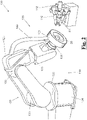
- an exemplary embodiment of an apparatus 100 for making a biocompatible three-dimensional object 30 provides an anthropomorphic robot 132 having a kinematical chain of pivot joints 133.
- Such chain of joints 133 is constrained at an end to a fixed base 134, and at another end to a support base 131 on which support body 20 engages in a removable way.
- the chain of pivot joints 133 of Fig. 1 allows handling the support body according to six degrees of freedom, allowing an optimum precision when generating the sought three-dimensional object 30.
- first delivery unit 110 is adapted to deliver a jet of a biomaterial of synthetic origin towards the support body 20.
- the second delivery unit 111 is, instead, arranged to deliver a jet of non-solvent, for example water, overlapping to the jet generated by first delivery unit 110, in order to induce a quick deposit of the biopolymeric material supplied onto support body 20 by first delivery unit 110, allowing to obtain a filamentous three-dimensional structure.
- the third delivery unit is adapted to deliver a third biocompatible fluid substance diluted in solution, in particular another biomaterial of synthetic or biological origin.
- Each delivery unit 110, 111,112 also has a hydraulic circuit (not shown in the figure, for example, a cylinder-piston mechanism) consisting of ducts, with possible valves and pumps, which connect the or each delivery unit to reservoirs containing the biocompatible fluid substances.
- a hydraulic circuit (not shown in the figure, for example, a cylinder-piston mechanism) consisting of ducts, with possible valves and pumps, which connect the or each delivery unit to reservoirs containing the biocompatible fluid substances.
- a suction and/or blowing unit 120 is further provided, adapted to generate a suction and/or blowing current.
- the suction and/or blowing unit 120 makes it possible to level the thickness of the coating layer 35 and to remove from support body 20 any surplus particles of the biocompatible fluid substances supplied by the or each delivery unit 110, 111, 112.
- the device 120 is also spatially moved by auxiliary moving means 140, in such a way that this device 120 can follow spatially the position of support body 20 during its handling steps by handling unit 130.
- the base 134 of the handling unit 130 can be automated or free such that it is controlled by a user.
- the structure of the handling unit 130 is not limited to the structure shown in the figures.
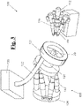
- a second exemplary embodiment is shown, which differs from an exemplary embodiment of Fig. 1 as from the type of the device 120.
- device 120 includes a toroidal suction hood 121, which is integral to support base 131 and is configured to surround laterally support body 20.
- Toroidal hood 121 is then joined to a suction tube 122 arranged in turn to connect pneumatically the suction hood 121 with a suction system 123 that has a compressor to generate a suction flow and with a storage reservoir containing any surplus particles of the dispensed fluid substance.
- device 120 is a blowing device including a compressor adapted to generate a blowing current for removing any surplus particles of the delivered fluid substance.
- auxiliary handling unit 140 like the exemplary embodiment of Fig. 1 , since the toroidal hood 121 surrounds laterally the support body 20, whichever is the position reached by handling unit 130.
- any surplus particles of the delivered fluid substance can be removed by laser or other abrading method.
- handling unit 130 instead of including the anthropomorphic robot 132 of the previous figures, includes a plurality of linear actuators 133, each of which engages, at one end, to fixed base 134, and at another end, to support base 131.
- Support body 20 engages in a removable way with support base 131, like the previous exemplary embodiments.
- the handling unit can reach the same degrees of freedom of an anthropomorphic robot, even if with narrower handling range.
- the advantage offered by this solution is shown by a high reduction of the encumbrance.
- Fig. 4 the step is shown of pressing, in particular to hot pressing, of the coating layer 35 deposited by the or each delivery unit 110,111, 112, using a counter-mold 150.
- the coating layer 35 is then removed from support body 20 and becomes substantially the final biocompatible three-dimensional object 30, visible in Fig. 5 .
- biocompatible three-dimensional objects 30 of whichever shape.
- biocompatible three-dimensional objects 30 can be manufactured both of simple and regular shape, such as a tetrahedron or a cone, and of irregular shape and/or with surfaces which cannot worked out in a simple way, such as a concave or convex patch or an ellipsoidal patch.
- biocompatible three-dimensional objects 30 can be provided having surfaces with different radius of curvature and/or with different angles.
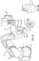
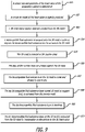
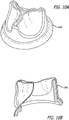
- a cardiac chamber of a human heart is shown to which a biocompatible three-dimensional object 30 is mounted, in particular a heart patch, consisting of an inner portion 30a and an external portion 30b.
- Fig. 6B part of the apparatus 100 including the support 20 is shown, from which the inner portion 30a of the heart patch of Fig. 6A is generated.
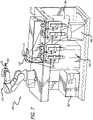
- Fig. 7 discloses a system 700 for making a synthetic, biocompatible three-dimensional (3D) heart valve 701 (shown in Fig. 13 A) .
- the system 700 includes an anthropomorphic robot 132 (e.g.; ABB IRB 120 industrial robot or the like), as described above, stationed on a workbench 712.
- the system also includes a 3D mold 702 mounted on a support body 20.
- the 3D mold 702 is for a heart valve, however, the mold maybe shaped to design for any other object.
- the anthropomorphic robot 132 also includes a chuck 131 to releasably hold the support body 20 and the 3D mold 702.
- Two spray guns 110 and 111 are also shown disposed on the workbench 712.
- a person skilled in the art can appreciate that a plurality of spray guns can be used depending on the desired heart valve structure.
- the system may have up to 10 delivery units or spray guns.
- Also attached to the workbench 712 are two continuous pumps 704 and an air compressor 705.
- a chemical container 706 is also shown, and the chemical container 706 may store one or more biocompatible fluid substances, to be sprayed on the 3D mold 702.
- multiple containers may be used to store different biocompatible substances to be sprayed through one or both of the spray guns 110 and 111.
- the chemical container 706 is attached to one or both of the two continuous pumps 704.
- An electronic control unit 707 may be disposed on or near the workbench 712 and be in communication with the anthropomorphic robot 132. In one embodiment, the electronic control unit 707 may supply power and operating instructions to the anthropomorphic robot 132, pumps 704, air compressor 705, and/or spray guns 110 and 111.
- a suction and/or blowing unit 120 (not shown in Fig. 7 ) may also be provided with the system 700.
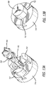
- Fig. 8A discloses a close up view of the top section of the system 700 including the anthropomorphic robot 132, the 3D mold 702, two spray guns 110 and 111, and a suction and/or blowing unit 120.
- the anthropomorphic robot 132 includes a kinematical chain of pivot joints 133.
- Such chain of joints 133 is constrained at an end to a fixed base 134, and at another end to a support base 131 on which support body 20 engages in a removable way.
- the support base 131 may be a chuck in certain embodiments.
- the chain of pivot joints 133 allows handling of the support body according to six degrees of freedom, which in turn allows an optimum precision when generating the sought 3D heart valve 701.
- first delivery unit 110 is adapted to deliver a jet of a biomaterial of synthetic origin towards the 3D mold 702 in the same manner as described above with reference to spray coating the support body 20.
- the second delivery unit 111 is arranged to deliver a jet of non-solvent, for example, water, overlapping to the jet generated by the first delivery unit 110 in order to induce a quick deposit of the biopolymeric material supplied onto 3D mold 702 by the first delivery unit 110. Subsequently, obtaining a filamentous 3D structure of the desired heart valve 701.
- Fig. 8A also shows a suction and/or blowing unit 120 to generate suction and/or blowing current.
- the suction and/or blowing unit 120 By using the suction and/or blowing unit 120 the thickness of a coating layer on the 3D mold 702 can be levelled and surplus particles of the biocompatible fluid substances supplied by each delivery unit 110 and 111 lean be removed from support body 20.
- the delivery units 110 and 111 are equipped with a 90 degree end axis in order to check the spraying process over a 3D valve shape.
- the delivery units 110 and 111 may move about an axis during the spraying process to create the 3D valve shape.
- Fig. 8B shows an exploded view of the 3D mold.
- the suction and/or blowing unit 120 is also spatially moved by auxiliary moving means 140, in such a way that this device 120 can follow spatially the position of 3D mold 702 during its handling steps by handling unit 130 (also as described above).
- the suction and/or blowing unit 120 can host a removable platform for maintenance aims.
- Fig. 9 discloses a method 900 to make the synthetic, biocompatible 3D heart valve 701 of this example using the anthropomorphic robot 133.
- the anthropomorphic robot may have three to six degrees of freedom.
- a proper size and geometry of the heart valve 701 of the prospective patient is determined.
- sizing the heart valve 701 is achieved by scanning (e.g.; via CT, FL, DR, MRI and the like) or visually inspecting the implantation site (i.e.; prospective patient's heart).
- the geometry of the heart valve is selected based on the desired characteristic of the heart valve 701 (shown in Fig. 13 A) .
- Such geometry may differ depending on the size and condition of the heart of the patient.
- a heart valve 701 with asymmetrical leaflets geometry may be chosen.
- Such design geometry may offer improved valvular closure capability and may preserve opening efficiency.
- a heart valve with a narrow orifice 1101 geometry may be chosen, which offers biocompatible design, simple leaflets geometry and good closure capability.
- a heart valve with a symmetrical leaflets design 1201 may be chosen, which may offer improved valve opening, since the warps in this design increases the surface of each leaflets. It should be understood that various designs may be chosen for the heart valve depending on the desired characteristics for the patient.
- a virtual 3D model 708 of the heart valve 701 is digitally produced.
- a 3D model 708 of the desired heart valve may be created by hand or other machinery, it is preferred to create a virtual 3D model 708 of the heart valve.
- the virtual 3D model 708 may be created using 3D computer-aided design (CAD) software.
- a 3D mold 702 and a counter mold 709 may be created from the virtual 3D model 708.
- Different techniques for example, 3D rapid prototyping process, vacuum casting, 3D printing, or the like, can be used to create the 3D mold 702 and the counter mold 709.
- the mold and the counter mold can be made of steel to improve the quality of the 3D heart valve architecture.
- a stent 710 can be placed on the 3D mold 702, in order to incorporate the stent into the inner walls of the 3D heart valve 701.
- a stent 710 incorporated with the heart valve 701 is best shown in the exploded view of Fig. 13 A .
- the stent 710 can be incorporated into the heart valve 701 by forming a coating around the stent 710 and the 3D mold 702 during the spraying process to form the heart valve 701.
- the stent 710 can be incorporated into the heart valve 701 after the heart valve 701 is created. This may be done by attaching the stent 710 inside or around the exterior surface of the heart valve 701.
- a stent 710 maintains the cross-sectional shape of the 3D heart valve 701 and can help secure the 3D heart valve 701 within the patient, e.g., by suturing the stent and valve in position within the patient.
- the cross-sectional shape of the heart valve is generally circular in shape at one end, however the cross sectional shape of the heart valve may take on other shapes.
- Stents usually are made of metal mesh, but sometimes they can be made of fabric.
- a biocompatible fluid substance is sprayed onto the 3D mold 702 in order to deposit the biocompatible fluid substance on the surface of the 3D mold 702, and in certain embodiments, on the surface of a stent 710 too.
- the spraying of the biocompatible fluid substance onto the 3D mold 702 is shown in Figs. 7 and 8 .
- different biocompatible fluids for example, biocompatible polymeric resin, elastomer biomaterial, polyurethane, silicone based fluids, or the like can be used depending on the desired characteristics of the heart valve 701.
- the 3D mold 702 including the coating forming the heart valve 701, and the stent 710 in certain embodiments is removed from the chuck 131 of the robot 133 and is inserted in a mandrel 714 including the counter mold 709.
- the mandrel 714 will accept the mold 702 in a recess.
- jaws 713 of the counter mold 709 are moved from the edge of the mandrel 714 towards the 3D mold 702 via the slots 711 of the mandrel 714 and pressed against the newly created valve on the 3D mold 702.
- the jaws 713 of the counter mold 709 can be moved towards the 3D mold 702 via the slots 711 manually or automatically.
- the design of the counter mold 709 can help to obtain a better surface quality and reduced porosity of the 3D heart valve 701.
- hot pressing can be used to achieve an optimum finishing of the shape of the 3D heart valve 701, in such a way that such shape is closest to the 3D mold 702. Hot pressing also improves the mechanical features of the 3D valve 701.
- the biocompatible fluid substance on the 3D mold 702 is cured.
- the 3D mold may be cured in an oven between 70° and 90° Celsius for approximately 20 to 40 minutes. It is known that the temperature and time for curing in an oven could vary depending on the type of biocompatible fluid substance being used to form the 3D mold 702.
- the newly created heart valve 701 can be allowed to cool in situ.
- the 3D mold may be cured without using an oven, for example, by cold curing the 3D mold with chemicals or other process.
- a portion of the mold may extend past the ends (top side) of the jaws 713 of the counter mold 709.
- the portion of the mold extending past the jaws 713 is cut in order to form and obtain the desired shape of the valve leaflets.
- This cut of the mold affects the end portion (distal end) of the valve leaflets.
- the cut to form the distal end of the leaflets is made with a blade, such as a scalpel.
- the cut may be made with a robotic arm or machine using a blade, and in certain embodiments, the cut may be made manually.
- a laser may be used to cut the distal end of the leaflets. The laser may be manually controlled or controlled by a machine or robotic arm.
- the dry biocompatible fluid substance layer coated 3D mold 702, and stent in certain embodiments, on the support body 20 is extracted from the counter mold 709.
- the dry biocompatible fluid substance layer on the 3D mold 702 becomes final biocompatible 3D heart valve 701.
- the newly created 3D heart valve 701 is sterilized.
- the newly created 3D heart valve 701 includes the dried biocompatible fluid substance layer, and stent in certain embodiments.
- the valve 701 may be sterilized by wet or steam sterilization, dry heat sterilization, ethylene oxide, sporicidal chemicals, glass plasma, irradiation (gamma rays), or the like.
- a surgeon may implant the 3D heart valve 701, including the stent in certain embodiments, in the heart of the patient.
- the synthetic heart valve 701 produced using the method 900 is cost effective, biocompatible, rapidly manufactured, highly customizable, and durable.
- the heart valve 701 can be produced directly from the 3D model 708, via 3D printing, CNC machining, or other methods.
- the spraying technique as described in Fig. 9 , for a singular valve can be completed less than 30-40 minutes.
- valves produced by the 3D spraying technique have very high biocompatibility and strong structural resistance. Therefore, the production process 900, as disclosed herein, dramatically decreases costs and permits easy production of variable sizes and geometries, making it suitable for veterinary use. This makes the process 900 ideal to for the application that requires low implant cost and great dimensional to accommodate the greatly varying valves of different species of animal.
- a prosthetic 3D human heart valve can also be produced using the process 900. It should also be appreciated that any type of prosthetic heart valve, such as a single leaflet valve, bileaflet valve, tilting disc valve, cage and ball valve, bicuspid valve, a mechanical valve, or the like may be used.
Claims (15)
- Procédé permettant la fabrication d'une valvule cardiaque tridimensionnelle biocompatible (701), le procédé comprenant les étapes de :- distribution d'au moins une substance fluide biocompatible vers un moule (702) possédant une surface de moule pour obtenir une couche de revêtement d'épaisseur prédéfinie conçue pour revêtir la surface de moule, à l'aide d'au moins une unité de distribution (110, 111), la substance fluide biocompatible comprenant une pluralité de particules ;- manipulation, avec une unité de manipulation (130), du moule (702) et de l'unité de distribution (110, 111) afin de fournir un mouvement relatif avec au moins trois degrés de liberté entre le moule (702) et l'unité de distribution (110, 111), le moule revêtu de l'au moins une substance fluide biocompatible qui est distribuée pour obtenir une valvule cardiaque tridimensionnelle (701) possédant une surface correspondant à la surface de moule ;- retrait du moule (702) de toutes les particules excédentaires de l'au moins une substance fluide biocompatible distribuée à l'aide d'une unité d'aspiration et de soufflage (120) afin d'homogénéiser l'épaisseur prédéfinie de la couche de revêtement ; et- pressage d'un contre-moule (709) sur la couche de revêtement déposée sur le moule (702) après distribution de la substance fluide biocompatible.
- Procédé selon la revendication 1, comprenant en outre la détermination d'une taille et d'une géométrie de la valvule cardiaque (701), ladite géométrie de la valvule cardiaque (701) étant choisie dans le groupe constitué d'un orifice étroit, de feuillets symétriques et de feuillets asymétriques.
- Procédé selon la revendication 2, comprenant en outre la production, à l'aide d'un processeur informatique, d'un modèle tridimensionnel virtuel de la valvule cardiaque (701).
- Procédé selon la revendication 3, comprenant en outre la création du moule (702) et du contre-moule (709) sur la base du modèle tridimensionnel virtuel de la valvule cardiaque (701).
- Procédé selon la revendication 1, ladite au moins une substance fluide biocompatible étant choisie dans le groupe constitué d'une résine polymère biocompatible, d'un biomatériau élastomère, du polyuréthane et du silicone.
- Procédé selon la revendication 1, comprenant en outre le durcissement et le séchage du moule revêtu de l'au moins une substance fluide biocompatible in situ.
- Système conçu pour fabriquer une valvule cardiaque tridimensionnelle biocompatible (701), le système comprenant :- au moins une unité de distribution (110, 111) conçue pour distribuer au moins une substance fluide biocompatible vers un moule (702) possédant une surface de moule pour obtenir une couche de revêtement d'épaisseur prédéfinie conçue pour revêtir la surface de moule, la substance fluide biocompatible possédant une pluralité de particules ;- une unité de manipulation (130) conçue pour fournir un mouvement relatif avec au moins trois degrés de liberté entre le moule (702) et l'unité de distribution (110, 111), ledit moule (702) étant revêtu de ladite au moins une substance fluide biocompatible qui est distribuée pour obtenir une valvule cardiaque tridimensionnelle (701) possédant une surface correspondant à la surface de moule ;- une unité d'aspiration et de soufflage (120) conçue pour générer un courant d'aspiration et de soufflage, ledit courant d'aspiration et de soufflage éliminant du moule (702) toutes les particules excédentaires de la substance fluide biocompatible fournie par l'unité de distribution (110, 111) ;- un contre-moule (709) adapté pour presser la couche de revêtement déposée sur le moule (702).
- Système selon la revendication 7, ladite unité de manipulation (130) comprenant un robot anthropomorphe (132) possédant une chaîne d'articulations pivots (133), la chaîne d'articulations pivots (133) possédant une première extrémité reliée à une base fixe (134) et une seconde extrémité reliée à une base de support (131) sur laquelle le moule (702) est monté de manière amovible, la chaîne d'articulations pivots (133) étant agencée pour déplacer le moule (702), selon au moins 6 degrés de liberté.
- Système selon la revendication 7, ladite unité de manipulation (130) comprenant une pluralité d'actionneurs linéaires, chaque actionneur de la pluralité possédant une première extrémité en prise avec une base fixe (134) et une seconde extrémité en prise avec une base de support (131) sur laquelle le moule (702) est monté de façon amovible.
- Système selon la revendication 7, ladite unité d'aspiration et de soufflage (120) étant mobile et associée à un moteur agencé pour déplacer l'unité d'aspiration et de soufflage (120), ledit moteur étant configuré pour permettre à l'unité d'aspiration et de soufflage (120) de suivre spatialement la position du moule (702) durant sa manipulation par l'unité de manipulation (130).
- Système selon la revendication 7, ladite unité d'aspiration et de soufflage (120) comprenant une hotte d'aspiration solidaire de la base de support (131) et conçue pour entourer latéralement le moule (702) afin de maximiser l'aspiration des particules en surplus de la substance fluide biocompatible, et un tube d'aspiration agencé pour relier pneumatiquement la hotte d'aspiration à un système d'aspiration afin de générer un flux d'aspiration.
- Système selon la revendication 7, ladite au moins une unité de distribution (110, 111) comprenant une première unité de distribution (110) agencée pour distribuer un premier jet d'une première substance fluide biocompatible vers le moule (702), la première substance fluide biocompatible étant une biomatériau d'origine synthétique, et une seconde unité de distribution (111) agencée pour distribuer un second jet d'une seconde substance fluide biocompatible vers le moule (702), la seconde substance fluide biocompatible étant un non-solvant, ladite seconde unité de distribution (111) étant agencée pour diriger le second jet de distribution vers le moule (702) d'une façon telle que le second jet de distribution est chevauché par le premier jet de distribution, induisant un dépôt rapide du biomatériau synthétique fourni sur le moule (702) à partir de la première unité de distribution (110) obtenant une structure tridimensionnelle filamenteuse.
- Système selon la revendication 12, ladite au moins une unité de distribution (110, 111) comprenant en outre une pluralité d'unités de distribution (110, 111) agencées pour distribuer une pluralité de substances fluides biocompatibles.
- Système selon la revendication 13, ladite pluralité de substances fluides biocompatibles comprenant un matériau biopolymère d'origine synthétique.
- Système selon la revendication 8, comprenant en outre une unité de commande électronique en communication avec le robot anthropomorphe (132), l'unité de commande électronique fournit de l'énergie et des instructions de fonctionnement au robot anthropomorphe (132) et à l'unité de distribution (110, 111).
Applications Claiming Priority (2)
| Application Number | Priority Date | Filing Date | Title |
|---|---|---|---|
| US14/852,326 US10654200B2 (en) | 2013-03-07 | 2015-09-11 | Apparatus and method for producing a biocompatible three-dimensional object |
| PCT/IB2016/001377 WO2017042627A1 (fr) | 2015-09-11 | 2016-09-08 | Appareil et procédé permettant de fabriquer un objet tridimensionnel biocompatible |
Publications (2)
| Publication Number | Publication Date |
|---|---|
| EP3347182A1 EP3347182A1 (fr) | 2018-07-18 |
| EP3347182B1 true EP3347182B1 (fr) | 2022-07-13 |
Family
ID=57286746
Family Applications (1)
| Application Number | Title | Priority Date | Filing Date |
|---|---|---|---|
| EP16794721.7A Active EP3347182B1 (fr) | 2015-09-11 | 2016-09-08 | Appareil et procédé pour produire un objet tridimensionnel biocompatible |
Country Status (2)
| Country | Link |
|---|---|
| EP (1) | EP3347182B1 (fr) |
| WO (1) | WO2017042627A1 (fr) |
Cited By (1)
| Publication number | Priority date | Publication date | Assignee | Title |
|---|---|---|---|---|
| US11617650B2 (en) | 2012-05-30 | 2023-04-04 | Neovasc Tiara Inc. | Methods and apparatus for loading a prosthesis onto a delivery system |
Families Citing this family (11)
| Publication number | Priority date | Publication date | Assignee | Title |
|---|---|---|---|---|
| US9554897B2 (en) | 2011-04-28 | 2017-01-31 | Neovasc Tiara Inc. | Methods and apparatus for engaging a valve prosthesis with tissue |
| EP3541462A4 (fr) | 2016-11-21 | 2020-06-17 | Neovasc Tiara Inc. | Procédés et systèmes de rétraction rapide d'un système de pose de valvule cardiaque transcathéter |
| CN106827518B (zh) * | 2017-04-10 | 2023-05-30 | 云南增材佳唯科技有限公司 | 一种串联式用于医用器械打印的光敏树脂3d打印一体机 |
| EP3672530A4 (fr) | 2017-08-25 | 2021-04-14 | Neovasc Tiara Inc. | Prothèse de valvule mitrale transcathéter à déploiement séquentiel |
| CN108988197B (zh) * | 2018-06-01 | 2020-01-03 | 南京理工大学 | 一种带电作业机器人系统带电作业现场的快速重构方法 |
| JP7260930B2 (ja) | 2018-11-08 | 2023-04-19 | ニオバスク ティアラ インコーポレイテッド | 経カテーテル僧帽弁人工補綴物の心室展開 |
| EP3946163A4 (fr) | 2019-04-01 | 2022-12-21 | Neovasc Tiara Inc. | Valve prothétique déployable de manière contrôlable |
| EP3972673A4 (fr) | 2019-05-20 | 2023-06-07 | Neovasc Tiara Inc. | Dispositif d'introduction avec mécanisme d'hémostase |
| WO2020257643A1 (fr) | 2019-06-20 | 2020-12-24 | Neovasc Tiara Inc. | Valve mitrale prothétique à profil bas |
| US11872123B2 (en) | 2020-12-10 | 2024-01-16 | GrOwnValve GmbH | Method for manufacturing a cardiac valve prosthesis |
| EP4011324A1 (fr) * | 2020-12-10 | 2022-06-15 | GrOwnValve GmbH | Procédé de fabrication d'un moule pour une prothèse valvulaire cardiaque |
Family Cites Families (7)
| Publication number | Priority date | Publication date | Assignee | Title |
|---|---|---|---|---|
| US5376117A (en) | 1991-10-25 | 1994-12-27 | Corvita Corporation | Breast prostheses |
| US7148058B2 (en) | 2000-06-05 | 2006-12-12 | Chiron Corporation | Protein microarrays on mirrored surfaces for performing proteomic analyses |
| US6953332B1 (en) * | 2000-11-28 | 2005-10-11 | St. Jude Medical, Inc. | Mandrel for use in forming valved prostheses having polymer leaflets by dip coating |
| WO2010059834A2 (fr) | 2008-11-20 | 2010-05-27 | Allergan, Inc. | Système et procédé de moulage de coquilles molles pour implants remplis de fluide |
| ITPI20090066A1 (it) | 2009-05-26 | 2010-11-27 | Consiglio Nazionale Ricerche | Metodo per produrre un dispositivo applicabile a tessuti biologici, in particolare un patch per trattare tessuti danneggiati, e dispositivo ottenuto con tale metodo |
| WO2013019416A1 (fr) * | 2011-07-29 | 2013-02-07 | St. Jude Medical, Inc. | Mandrin plongeant à interstice |
| ITPI20130015A1 (it) * | 2013-03-07 | 2014-09-08 | S M Scienzia Machinale S R L | Apparecchiatura e metodo per la produzione di un oggetto tridimensionale biocompatibile |
-
2016
- 2016-09-08 WO PCT/IB2016/001377 patent/WO2017042627A1/fr active Application Filing
- 2016-09-08 EP EP16794721.7A patent/EP3347182B1/fr active Active
Cited By (1)
| Publication number | Priority date | Publication date | Assignee | Title |
|---|---|---|---|---|
| US11617650B2 (en) | 2012-05-30 | 2023-04-04 | Neovasc Tiara Inc. | Methods and apparatus for loading a prosthesis onto a delivery system |
Also Published As
| Publication number | Publication date |
|---|---|
| WO2017042627A1 (fr) | 2017-03-16 |
| EP3347182A1 (fr) | 2018-07-18 |
Similar Documents
| Publication | Publication Date | Title |
|---|---|---|
| US10946561B2 (en) | Apparatus and method for producing a biocompatible three-dimensional object | |
| EP3347182B1 (fr) | Appareil et procédé pour produire un objet tridimensionnel biocompatible | |
| US11738483B2 (en) | Method for producing a biocompatible three-dimensional object | |
| Attarilar et al. | 3D printing technologies in metallic implants: a thematic review on the techniques and procedures | |
| US11325301B2 (en) | 3D printing equipment utilizing biological material, and method | |
| US7959847B2 (en) | Methods for multi-material stereolithography | |
| EP3094477A1 (fr) | Impression 3d de prothèses faciales | |
| EP3417828B1 (fr) | Procédé de fabrication d'un implant avec un matériau d'impression tridimensionnelle à base de titane | |
| CA2573850A1 (fr) | Modele d'anevrisme aortique abdominal pour tests de fatigue | |
| CN106029018A (zh) | 具有内部框架和外部涂层的眼外科器械 | |
| CN110393610B (zh) | 一种三层复合骨植入假体及其制备方法 | |
| WO2013160651A1 (fr) | Valvule | |
| AU2019252128B2 (en) | 3D bioprinting a medical device through freeform reversible embedding | |
| US20180140396A1 (en) | Dental prosthetic | |
| US20230390996A1 (en) | Additive manufacturing device, method and medical device therefor | |
| Long Ng et al. | Material Aspects of Additively Manufactured Medical Devices | |
| Wicker et al. | Methods for multi-material stereolithography | |
| Zibner et al. | High precision 2.5 D laser cutting of thin nitinol and polyurethane for medical applications | |
| Bagheri | Contribution to the manufacture of porous structures for prostheses by means |
Legal Events
| Date | Code | Title | Description |
|---|---|---|---|
| STAA | Information on the status of an ep patent application or granted ep patent |
Free format text: STATUS: UNKNOWN |
|
| STAA | Information on the status of an ep patent application or granted ep patent |
Free format text: STATUS: THE INTERNATIONAL PUBLICATION HAS BEEN MADE |
|
| PUAI | Public reference made under article 153(3) epc to a published international application that has entered the european phase |
Free format text: ORIGINAL CODE: 0009012 |
|
| STAA | Information on the status of an ep patent application or granted ep patent |
Free format text: STATUS: REQUEST FOR EXAMINATION WAS MADE |
|
| 17P | Request for examination filed |
Effective date: 20180406 |
|
| AK | Designated contracting states |
Kind code of ref document: A1 Designated state(s): AL AT BE BG CH CY CZ DE DK EE ES FI FR GB GR HR HU IE IS IT LI LT LU LV MC MK MT NL NO PL PT RO RS SE SI SK SM TR |
|
| AX | Request for extension of the european patent |
Extension state: BA ME |
|
| DAV | Request for validation of the european patent (deleted) | ||
| DAX | Request for extension of the european patent (deleted) | ||
| STAA | Information on the status of an ep patent application or granted ep patent |
Free format text: STATUS: EXAMINATION IS IN PROGRESS |
|
| STAA | Information on the status of an ep patent application or granted ep patent |
Free format text: STATUS: EXAMINATION IS IN PROGRESS |
|
| 17Q | First examination report despatched |
Effective date: 20201014 |
|
| STAA | Information on the status of an ep patent application or granted ep patent |
Free format text: STATUS: EXAMINATION IS IN PROGRESS |
|
| GRAP | Despatch of communication of intention to grant a patent |
Free format text: ORIGINAL CODE: EPIDOSNIGR1 |
|
| STAA | Information on the status of an ep patent application or granted ep patent |
Free format text: STATUS: GRANT OF PATENT IS INTENDED |
|
| INTG | Intention to grant announced |
Effective date: 20220201 |
|
| RAP3 | Party data changed (applicant data changed or rights of an application transferred) |
Owner name: S.M. SCIENZIA MACHINALE S.R.L |
|
| RIN1 | Information on inventor provided before grant (corrected) |
Inventor name: SOLDANI, GEORGIO Inventor name: BACCHERETI, MARCO Inventor name: BOSIO, LUCA |
|
| GRAS | Grant fee paid |
Free format text: ORIGINAL CODE: EPIDOSNIGR3 |
|
| GRAA | (expected) grant |
Free format text: ORIGINAL CODE: 0009210 |
|
| STAA | Information on the status of an ep patent application or granted ep patent |
Free format text: STATUS: THE PATENT HAS BEEN GRANTED |
|
| AK | Designated contracting states |
Kind code of ref document: B1 Designated state(s): AL AT BE BG CH CY CZ DE DK EE ES FI FR GB GR HR HU IE IS IT LI LT LU LV MC MK MT NL NO PL PT RO RS SE SI SK SM TR |
|
| RAP3 | Party data changed (applicant data changed or rights of an application transferred) |
Owner name: S.M. SCIENZIA MACHINALE S.R.L |
|
| REG | Reference to a national code |
Ref country code: CH Ref legal event code: EP |
|
| REG | Reference to a national code |
Ref country code: DE Ref legal event code: R096 Ref document number: 602016073516 Country of ref document: DE |
|
| REG | Reference to a national code |
Ref country code: IE Ref legal event code: FG4D |
|
| REG | Reference to a national code |
Ref country code: AT Ref legal event code: REF Ref document number: 1504039 Country of ref document: AT Kind code of ref document: T Effective date: 20220815 |
|
| REG | Reference to a national code |
Ref country code: LT Ref legal event code: MG9D |
|
| REG | Reference to a national code |
Ref country code: NL Ref legal event code: MP Effective date: 20220713 |
|
| PG25 | Lapsed in a contracting state [announced via postgrant information from national office to epo] |
Ref country code: SE Free format text: LAPSE BECAUSE OF FAILURE TO SUBMIT A TRANSLATION OF THE DESCRIPTION OR TO PAY THE FEE WITHIN THE PRESCRIBED TIME-LIMIT Effective date: 20220713 Ref country code: RS Free format text: LAPSE BECAUSE OF FAILURE TO SUBMIT A TRANSLATION OF THE DESCRIPTION OR TO PAY THE FEE WITHIN THE PRESCRIBED TIME-LIMIT Effective date: 20220713 Ref country code: PT Free format text: LAPSE BECAUSE OF FAILURE TO SUBMIT A TRANSLATION OF THE DESCRIPTION OR TO PAY THE FEE WITHIN THE PRESCRIBED TIME-LIMIT Effective date: 20221114 Ref country code: NO Free format text: LAPSE BECAUSE OF FAILURE TO SUBMIT A TRANSLATION OF THE DESCRIPTION OR TO PAY THE FEE WITHIN THE PRESCRIBED TIME-LIMIT Effective date: 20221013 Ref country code: NL Free format text: LAPSE BECAUSE OF FAILURE TO SUBMIT A TRANSLATION OF THE DESCRIPTION OR TO PAY THE FEE WITHIN THE PRESCRIBED TIME-LIMIT Effective date: 20220713 Ref country code: LV Free format text: LAPSE BECAUSE OF FAILURE TO SUBMIT A TRANSLATION OF THE DESCRIPTION OR TO PAY THE FEE WITHIN THE PRESCRIBED TIME-LIMIT Effective date: 20220713 Ref country code: LT Free format text: LAPSE BECAUSE OF FAILURE TO SUBMIT A TRANSLATION OF THE DESCRIPTION OR TO PAY THE FEE WITHIN THE PRESCRIBED TIME-LIMIT Effective date: 20220713 Ref country code: FI Free format text: LAPSE BECAUSE OF FAILURE TO SUBMIT A TRANSLATION OF THE DESCRIPTION OR TO PAY THE FEE WITHIN THE PRESCRIBED TIME-LIMIT Effective date: 20220713 Ref country code: ES Free format text: LAPSE BECAUSE OF FAILURE TO SUBMIT A TRANSLATION OF THE DESCRIPTION OR TO PAY THE FEE WITHIN THE PRESCRIBED TIME-LIMIT Effective date: 20220713 |
|
| REG | Reference to a national code |
Ref country code: AT Ref legal event code: MK05 Ref document number: 1504039 Country of ref document: AT Kind code of ref document: T Effective date: 20220713 |
|
| PG25 | Lapsed in a contracting state [announced via postgrant information from national office to epo] |
Ref country code: PL Free format text: LAPSE BECAUSE OF FAILURE TO SUBMIT A TRANSLATION OF THE DESCRIPTION OR TO PAY THE FEE WITHIN THE PRESCRIBED TIME-LIMIT Effective date: 20220713 Ref country code: IS Free format text: LAPSE BECAUSE OF FAILURE TO SUBMIT A TRANSLATION OF THE DESCRIPTION OR TO PAY THE FEE WITHIN THE PRESCRIBED TIME-LIMIT Effective date: 20221113 Ref country code: HR Free format text: LAPSE BECAUSE OF FAILURE TO SUBMIT A TRANSLATION OF THE DESCRIPTION OR TO PAY THE FEE WITHIN THE PRESCRIBED TIME-LIMIT Effective date: 20220713 Ref country code: GR Free format text: LAPSE BECAUSE OF FAILURE TO SUBMIT A TRANSLATION OF THE DESCRIPTION OR TO PAY THE FEE WITHIN THE PRESCRIBED TIME-LIMIT Effective date: 20221014 |
|
| REG | Reference to a national code |
Ref country code: DE Ref legal event code: R097 Ref document number: 602016073516 Country of ref document: DE |
|
| PG25 | Lapsed in a contracting state [announced via postgrant information from national office to epo] |
Ref country code: SM Free format text: LAPSE BECAUSE OF FAILURE TO SUBMIT A TRANSLATION OF THE DESCRIPTION OR TO PAY THE FEE WITHIN THE PRESCRIBED TIME-LIMIT Effective date: 20220713 Ref country code: RO Free format text: LAPSE BECAUSE OF FAILURE TO SUBMIT A TRANSLATION OF THE DESCRIPTION OR TO PAY THE FEE WITHIN THE PRESCRIBED TIME-LIMIT Effective date: 20220713 Ref country code: MC Free format text: LAPSE BECAUSE OF FAILURE TO SUBMIT A TRANSLATION OF THE DESCRIPTION OR TO PAY THE FEE WITHIN THE PRESCRIBED TIME-LIMIT Effective date: 20220713 Ref country code: DK Free format text: LAPSE BECAUSE OF FAILURE TO SUBMIT A TRANSLATION OF THE DESCRIPTION OR TO PAY THE FEE WITHIN THE PRESCRIBED TIME-LIMIT Effective date: 20220713 Ref country code: CZ Free format text: LAPSE BECAUSE OF FAILURE TO SUBMIT A TRANSLATION OF THE DESCRIPTION OR TO PAY THE FEE WITHIN THE PRESCRIBED TIME-LIMIT Effective date: 20220713 Ref country code: AT Free format text: LAPSE BECAUSE OF FAILURE TO SUBMIT A TRANSLATION OF THE DESCRIPTION OR TO PAY THE FEE WITHIN THE PRESCRIBED TIME-LIMIT Effective date: 20220713 |
|
| PLBE | No opposition filed within time limit |
Free format text: ORIGINAL CODE: 0009261 |
|
| STAA | Information on the status of an ep patent application or granted ep patent |
Free format text: STATUS: NO OPPOSITION FILED WITHIN TIME LIMIT |
|
| REG | Reference to a national code |
Ref country code: BE Ref legal event code: MM Effective date: 20220930 |
|
| PG25 | Lapsed in a contracting state [announced via postgrant information from national office to epo] |
Ref country code: SK Free format text: LAPSE BECAUSE OF FAILURE TO SUBMIT A TRANSLATION OF THE DESCRIPTION OR TO PAY THE FEE WITHIN THE PRESCRIBED TIME-LIMIT Effective date: 20220713 Ref country code: EE Free format text: LAPSE BECAUSE OF FAILURE TO SUBMIT A TRANSLATION OF THE DESCRIPTION OR TO PAY THE FEE WITHIN THE PRESCRIBED TIME-LIMIT Effective date: 20220713 |
|
| 26N | No opposition filed |
Effective date: 20230414 |
|
| PG25 | Lapsed in a contracting state [announced via postgrant information from national office to epo] |
Ref country code: LU Free format text: LAPSE BECAUSE OF NON-PAYMENT OF DUE FEES Effective date: 20220908 Ref country code: AL Free format text: LAPSE BECAUSE OF FAILURE TO SUBMIT A TRANSLATION OF THE DESCRIPTION OR TO PAY THE FEE WITHIN THE PRESCRIBED TIME-LIMIT Effective date: 20220713 |
|
| PG25 | Lapsed in a contracting state [announced via postgrant information from national office to epo] |
Ref country code: IE Free format text: LAPSE BECAUSE OF NON-PAYMENT OF DUE FEES Effective date: 20220908 |
|
| PG25 | Lapsed in a contracting state [announced via postgrant information from national office to epo] |
Ref country code: SI Free format text: LAPSE BECAUSE OF FAILURE TO SUBMIT A TRANSLATION OF THE DESCRIPTION OR TO PAY THE FEE WITHIN THE PRESCRIBED TIME-LIMIT Effective date: 20220713 |
|
| PG25 | Lapsed in a contracting state [announced via postgrant information from national office to epo] |
Ref country code: BE Free format text: LAPSE BECAUSE OF NON-PAYMENT OF DUE FEES Effective date: 20220930 |
|
| PGFP | Annual fee paid to national office [announced via postgrant information from national office to epo] |
Ref country code: IT Payment date: 20230921 Year of fee payment: 8 Ref country code: GB Payment date: 20230926 Year of fee payment: 8 |
|
| PGFP | Annual fee paid to national office [announced via postgrant information from national office to epo] |
Ref country code: FR Payment date: 20230926 Year of fee payment: 8 Ref country code: DE Payment date: 20230928 Year of fee payment: 8 |
|
| PGFP | Annual fee paid to national office [announced via postgrant information from national office to epo] |
Ref country code: CH Payment date: 20231001 Year of fee payment: 8 |
|
| PG25 | Lapsed in a contracting state [announced via postgrant information from national office to epo] |
Ref country code: HU Free format text: LAPSE BECAUSE OF FAILURE TO SUBMIT A TRANSLATION OF THE DESCRIPTION OR TO PAY THE FEE WITHIN THE PRESCRIBED TIME-LIMIT; INVALID AB INITIO Effective date: 20160908 |