EP3346934B1 - Multiport-zugangsvorrichtung für minimal-invasive chirurgische eingriffe - Google Patents
Multiport-zugangsvorrichtung für minimal-invasive chirurgische eingriffe Download PDFInfo
- Publication number
- EP3346934B1 EP3346934B1 EP16763171.2A EP16763171A EP3346934B1 EP 3346934 B1 EP3346934 B1 EP 3346934B1 EP 16763171 A EP16763171 A EP 16763171A EP 3346934 B1 EP3346934 B1 EP 3346934B1
- Authority
- EP
- European Patent Office
- Prior art keywords
- access device
- port
- assembly
- surgical procedures
- ring
- Prior art date
- Legal status (The legal status is an assumption and is not a legal conclusion. Google has not performed a legal analysis and makes no representation as to the accuracy of the status listed.)
- Active
Links
- 238000012978 minimally invasive surgical procedure Methods 0.000 title description 4
- 230000001012 protector Effects 0.000 claims description 98
- 238000001356 surgical procedure Methods 0.000 claims description 24
- 230000008878 coupling Effects 0.000 claims description 12
- 238000010168 coupling process Methods 0.000 claims description 12
- 238000005859 coupling reaction Methods 0.000 claims description 12
- 210000000683 abdominal cavity Anatomy 0.000 claims description 9
- 241000405070 Percophidae Species 0.000 claims description 6
- 230000007246 mechanism Effects 0.000 claims description 6
- 208000027418 Wounds and injury Diseases 0.000 description 99
- 238000000034 method Methods 0.000 description 11
- 241000272525 Anas platyrhynchos Species 0.000 description 10
- 230000013011 mating Effects 0.000 description 7
- 230000000712 assembly Effects 0.000 description 6
- 238000000429 assembly Methods 0.000 description 6
- 230000003068 static effect Effects 0.000 description 5
- 230000006835 compression Effects 0.000 description 3
- 238000007906 compression Methods 0.000 description 3
- 238000003780 insertion Methods 0.000 description 3
- 230000037431 insertion Effects 0.000 description 3
- CURLTUGMZLYLDI-UHFFFAOYSA-N Carbon dioxide Chemical compound O=C=O CURLTUGMZLYLDI-UHFFFAOYSA-N 0.000 description 2
- 230000009286 beneficial effect Effects 0.000 description 2
- 239000012530 fluid Substances 0.000 description 2
- 238000012830 laparoscopic surgical procedure Methods 0.000 description 2
- 238000011084 recovery Methods 0.000 description 2
- 239000000779 smoke Substances 0.000 description 2
- 206010003402 Arthropod sting Diseases 0.000 description 1
- 206010019909 Hernia Diseases 0.000 description 1
- 206010033372 Pain and discomfort Diseases 0.000 description 1
- 208000005646 Pneumoperitoneum Diseases 0.000 description 1
- 230000003187 abdominal effect Effects 0.000 description 1
- 238000007486 appendectomy Methods 0.000 description 1
- 229910002092 carbon dioxide Inorganic materials 0.000 description 1
- 239000001569 carbon dioxide Substances 0.000 description 1
- 238000002192 cholecystectomy Methods 0.000 description 1
- 230000003247 decreasing effect Effects 0.000 description 1
- 230000001419 dependent effect Effects 0.000 description 1
- 208000015181 infectious disease Diseases 0.000 description 1
- 208000014674 injury Diseases 0.000 description 1
- 238000002324 minimally invasive surgery Methods 0.000 description 1
- 238000012986 modification Methods 0.000 description 1
- 230000004048 modification Effects 0.000 description 1
- 238000013059 nephrectomy Methods 0.000 description 1
- 230000008439 repair process Effects 0.000 description 1
- 238000007789 sealing Methods 0.000 description 1
- -1 t Species 0.000 description 1
- 230000008733 trauma Effects 0.000 description 1
- 238000009941 weaving Methods 0.000 description 1
Images


Classifications
-
- A—HUMAN NECESSITIES
- A61—MEDICAL OR VETERINARY SCIENCE; HYGIENE
- A61B—DIAGNOSIS; SURGERY; IDENTIFICATION
- A61B17/00—Surgical instruments, devices or methods, e.g. tourniquets
- A61B17/34—Trocars; Puncturing needles
- A61B17/3417—Details of tips or shafts, e.g. grooves, expandable, bendable; Multiple coaxial sliding cannulas, e.g. for dilating
- A61B17/3421—Cannulas
- A61B17/3423—Access ports, e.g. toroid shape introducers for instruments or hands
-
- A—HUMAN NECESSITIES
- A61—MEDICAL OR VETERINARY SCIENCE; HYGIENE
- A61B—DIAGNOSIS; SURGERY; IDENTIFICATION
- A61B17/00—Surgical instruments, devices or methods, e.g. tourniquets
- A61B17/02—Surgical instruments, devices or methods, e.g. tourniquets for holding wounds open; Tractors
- A61B17/0218—Surgical instruments, devices or methods, e.g. tourniquets for holding wounds open; Tractors for minimally invasive surgery
-
- A—HUMAN NECESSITIES
- A61—MEDICAL OR VETERINARY SCIENCE; HYGIENE
- A61B—DIAGNOSIS; SURGERY; IDENTIFICATION
- A61B17/00—Surgical instruments, devices or methods, e.g. tourniquets
- A61B17/02—Surgical instruments, devices or methods, e.g. tourniquets for holding wounds open; Tractors
- A61B17/0293—Surgical instruments, devices or methods, e.g. tourniquets for holding wounds open; Tractors with ring member to support retractor elements
-
- A—HUMAN NECESSITIES
- A61—MEDICAL OR VETERINARY SCIENCE; HYGIENE
- A61B—DIAGNOSIS; SURGERY; IDENTIFICATION
- A61B17/00—Surgical instruments, devices or methods, e.g. tourniquets
- A61B17/34—Trocars; Puncturing needles
- A61B17/3462—Trocars; Puncturing needles with means for changing the diameter or the orientation of the entrance port of the cannula, e.g. for use with different-sized instruments, reduction ports, adapter seals
-
- A—HUMAN NECESSITIES
- A61—MEDICAL OR VETERINARY SCIENCE; HYGIENE
- A61B—DIAGNOSIS; SURGERY; IDENTIFICATION
- A61B17/00—Surgical instruments, devices or methods, e.g. tourniquets
- A61B17/34—Trocars; Puncturing needles
- A61B17/3474—Insufflating needles, e.g. Veress needles
-
- A—HUMAN NECESSITIES
- A61—MEDICAL OR VETERINARY SCIENCE; HYGIENE
- A61M—DEVICES FOR INTRODUCING MEDIA INTO, OR ONTO, THE BODY; DEVICES FOR TRANSDUCING BODY MEDIA OR FOR TAKING MEDIA FROM THE BODY; DEVICES FOR PRODUCING OR ENDING SLEEP OR STUPOR
- A61M13/00—Insufflators for therapeutic or disinfectant purposes, i.e. devices for blowing a gas, powder or vapour into the body
- A61M13/003—Blowing gases other than for carrying powders, e.g. for inflating, dilating or rinsing
-
- A—HUMAN NECESSITIES
- A61—MEDICAL OR VETERINARY SCIENCE; HYGIENE
- A61B—DIAGNOSIS; SURGERY; IDENTIFICATION
- A61B17/00—Surgical instruments, devices or methods, e.g. tourniquets
- A61B2017/00982—General structural features
- A61B2017/00991—Telescopic means
-
- A—HUMAN NECESSITIES
- A61—MEDICAL OR VETERINARY SCIENCE; HYGIENE
- A61B—DIAGNOSIS; SURGERY; IDENTIFICATION
- A61B17/00—Surgical instruments, devices or methods, e.g. tourniquets
- A61B17/34—Trocars; Puncturing needles
- A61B17/3417—Details of tips or shafts, e.g. grooves, expandable, bendable; Multiple coaxial sliding cannulas, e.g. for dilating
- A61B17/3421—Cannulas
- A61B2017/3437—Cannulas with means for removing or absorbing fluid, e.g. wicks or absorbent pads
-
- A—HUMAN NECESSITIES
- A61—MEDICAL OR VETERINARY SCIENCE; HYGIENE
- A61B—DIAGNOSIS; SURGERY; IDENTIFICATION
- A61B17/00—Surgical instruments, devices or methods, e.g. tourniquets
- A61B17/34—Trocars; Puncturing needles
- A61B17/3417—Details of tips or shafts, e.g. grooves, expandable, bendable; Multiple coaxial sliding cannulas, e.g. for dilating
- A61B17/3421—Cannulas
- A61B2017/3443—Cannulas with means for adjusting the length of a cannula
-
- A—HUMAN NECESSITIES
- A61—MEDICAL OR VETERINARY SCIENCE; HYGIENE
- A61B—DIAGNOSIS; SURGERY; IDENTIFICATION
- A61B17/00—Surgical instruments, devices or methods, e.g. tourniquets
- A61B17/34—Trocars; Puncturing needles
- A61B17/3417—Details of tips or shafts, e.g. grooves, expandable, bendable; Multiple coaxial sliding cannulas, e.g. for dilating
- A61B17/3421—Cannulas
- A61B2017/3445—Cannulas used as instrument channel for multiple instruments
-
- A—HUMAN NECESSITIES
- A61—MEDICAL OR VETERINARY SCIENCE; HYGIENE
- A61B—DIAGNOSIS; SURGERY; IDENTIFICATION
- A61B17/00—Surgical instruments, devices or methods, e.g. tourniquets
- A61B17/34—Trocars; Puncturing needles
- A61B17/3462—Trocars; Puncturing needles with means for changing the diameter or the orientation of the entrance port of the cannula, e.g. for use with different-sized instruments, reduction ports, adapter seals
- A61B2017/3466—Trocars; Puncturing needles with means for changing the diameter or the orientation of the entrance port of the cannula, e.g. for use with different-sized instruments, reduction ports, adapter seals for simultaneous sealing of multiple instruments
-
- A—HUMAN NECESSITIES
- A61—MEDICAL OR VETERINARY SCIENCE; HYGIENE
- A61M—DEVICES FOR INTRODUCING MEDIA INTO, OR ONTO, THE BODY; DEVICES FOR TRANSDUCING BODY MEDIA OR FOR TAKING MEDIA FROM THE BODY; DEVICES FOR PRODUCING OR ENDING SLEEP OR STUPOR
- A61M2205/00—General characteristics of the apparatus
- A61M2205/33—Controlling, regulating or measuring
- A61M2205/3331—Pressure; Flow
Definitions
- the subject invention is directed to surgical access devices, and more particularly, to a multi-port access device for minimally invasive surgical procedures including single incision laparoscopic procedures.
- Laparoscopic or "minimally invasive" surgical techniques are becoming commonplace in the performance of procedures such as cholecystectomies, appendectomies, hernia repair and nephrectomies. Benefits of such procedures include reduced trauma to the patient, reduced opportunity for infection, and decreased recovery time. Such procedures commonly involve filling or "insufflating" the abdominal (peritoneal) cavity with a pressurized fluid, such as carbon dioxide, to create what is referred to as a pneumoperitoneum.
- a pressurized fluid such as carbon dioxide
- the insufflation can be carried out by a surgical access device equipped to deliver insufflation fluid, or by a separate insufflation device, such as an insufflation (veress) needle.
- a surgical access device equipped to deliver insufflation fluid
- a separate insufflation device such as an insufflation (veress) needle.
- SurgiQuest, Inc., Milford, CT has developed unique surgical access devices that permit ready access to an insufflated surgical cavity without the need for conventional mechanical seals, and it has developed related gas delivery systems for providing sufficient pressure and flow rates to such access devices, as described in whole or in part in U.S. Patent No. 7,854,724 and U.S. Patent No. 8,795,223 .
- a surgeon makes three to four small incisions, usually no larger than about twelve millimeters each, which are made with the surgical access devices themselves, typically using a separate inserter or obturator placed therein. Following insertion, the inserter is removed, and the trocar allows access for instruments to be inserted into the abdominal cavity.
- a variety of larger access devices are also known in the art for accessing a surgical site through a single relatively large incision to perform minimally invasive procedures, rather than through multiple small incisions. Examples of such devices are disclosed in U.S. Patent Application Publication No. 2013/0012782 . Further, a surgical access device and methods providing seal movement in predefined paths is known from EP 2 226 027 A1 . Various methods and devices are provided for allowing multiple surgical instruments to be inserted into sealing elements of a single surgical access device. US 9 028 402 B2 further shows a surgical hand access apparatus. US 2010/081882 A2 shows a multiple port surgical access device.
- the subject invention is directed to a new and useful access device for surgical procedures.
- the device includes an elongated tubular body portion defining a longitudinal axis which is configured for introduction through a natural orifice of a body lumen or through a single incision formed in the wall of the abdominal cavity of a patient.
- the device further includes a multiport end cap operatively associated with a proximal end portion of the tubular body portion and including a plurality of separate access ports for accommodating the introduction of individual surgical instruments into the body lumen or abdominal cavity of the patient.
- a coupling is provided for operatively connecting the multiport end cap to the proximal end portion of the tubular body portion.
- the coupling is adapted and configured to permit relative axial rotation of the multiport end cap and tubular body portion.
- the coupling includes a ratchet mechanism for selectively positioning the multiport end cap relative to the tubular body portion.
- the coupling also includes spring loaded latches for selectively moving the ratchet mechanism.
- the coupling also includes a connector for a pressurized gas line and a connector for a pressure sensing line having a lumen extending from the pressure sensing line through a bottom surface thereof.
- the end cap includes a connector for a pressurized gas line and the tubular body portion includes a connector for a pressure sensing line.
- a seal assembly is operatively associated with each of the access ports of the end cap, and each seal assembly includes a main orifice seal and a secondary duckbill seal, and at least one of the access ports has a larger access diameter than the other access ports.
- the seal assembly can be secured within each access port with an external retaining feature.
- the retaining feature can include a locking mechanism selected from the group consisting of hooks, ratchet teeth, pins and holes, pins and slots, I-beams and pull and twist ties.
- the end cap can also include a trocar port.
- the multiport end cap can further include a weave layer to secure surgical instruments therethrough.
- an assembly aid can assist is engaging multiport cap with the tubular body portion.
- the tubular body portion can have an adjustable length.
- the subject is also directed to an access device for surgical procedures that includes a tubular adapter having opposed proximal and distal end portions, a multiport end cap including a plurality of separate access ports for accommodating the introduction of individual surgical instruments into the body lumen or abdominal cavity of the patient, a coupling for operatively connecting the multiport end cap to the proximal end portion of the tubular body portion, and a laparoscopic wound protector operatively associated with the distal end portion of the tubular adapter for introduction through a single incision formed in the wall of the abdominal cavity of a patient.
- a duckbill seal is operatively associated with the tubular adaptor.
- a generally S-shaped seal is operatively associated with the tubular adaptor.
- the subject is also directed to an access device for surgical procedures that includes a top ring having a plurality of circumferentially spaced apart openings extending therethrough.
- a latch assembly including diametrically opposed latches having a plurality of circumferentially spaced apart flexible tabs is configured to snap fit into corresponding openings of the top ring.
- a multiport end cap is operatively secured between the top ring and the latch assembly and includes a plurality of separate access ports for accommodating the introduction of individual surgical instruments into the body lumen or abdominal cavity of the patient.
- a retaining ring is operatively associated with the latch assembly and is configured to permit relative axial rotation of the multiport end cap.
- the retaining ring has a plurality of circumferentially spaced apart flexible tabs.
- a bottom ring has a plurality of circumferentially spaced apart openings extending therethrough for accepting corresponding flexible tabs of the retaining ring therein.
- An adapter is operatively secured between the retaining ring and the bottom ring.
- the adapter is a duck bill seal.
- the adapter is a seal having a generally S shape.
- an elongated tubular body portion can extend distally from the adapter configured for introduction through a natural orifice of a body lumen or through a single incision formed in the wall of the abdominal cavity of a patient.
- the retaining ring includes a first connector for a pressurized gas line and a connector for a second pressure sensing line.
- the retaining ring can further include an O-ring seal positioned within an annular groove thereof.
- the retaining ring can also include a ratchet mechanism for selectively positioning the multiport end cap relative to the adapter.
- a plurality of suture tie down flanges extends outwardly from the bottom ring.
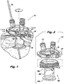
- Fig. 1 a multi-port access device for single incisions minimally invasive surgical procedures in accordance with a preferred embodiment of the subject invention and designated generally by reference numeral 100. It will be understood by those skilled in the art that embodiments of the multi-port access device shown and described herein can be used for any procedure through a single opening or incision including, but not limited to, rectal (TAMIS) procedures and laparoscopic procedures.
- TAMIS rectal
- a fully assembled multi-port access device 100 is shown positioned within a single opening of a patient.
- the access device 100 allows for a plurality of surgical instruments 104 to be inserted through one incision or natural body lumen providing more options for a surgeon. Also, using natural orifices when possible improves the patient's recovery time, pain and discomfort.
- the access device 100 is configured and designed to cooperate with an air seal line 106 and a sensing line 108 during a surgical procedure.
- the access device 100 includes a multi-port assembly 200 coupled to a wound protector assembly 300.
- the wound protector assembly 300 is generally an elongated tubular body portion 304 defining a longitudinal axis.
- the multi-port assembly 200 is operatively associated with a proximal end portion 304a of the tubular body portion 300.
- a coupling connects the multi-port assembly 200 and wound protector assembly 300 and is configured to allow 360 degree rotation of the multi-port assembly 200 without moving the air seal 106 or pressure sensing lines 108.
- the multi-port assembly 200 is comprised of an elastic access portion 210 and a latch assembly 240 (shown best in Fig. 4 ).
- the elastic access portion 210 is generally dome shaped and includes a plurality of access ports 212 for insertion of surgical instruments therethrough 104.
- the latch assembly 240 couples the multi-port assembly 200 to a ratchet ring 312 (shown in Fig. 3 ) of the wound protector assembly 300.
- each access port 212 of the elastic access portion 210 includes a seal assembly 220 and a retaining feature 214 for maintaining the seal assembly 220 in position.
- the seal assembly 220 includes a top 222 which encloses a main seal 224 and a duck bill seal 226 between the top 222 and a bottom ring 228.
- the top 222 and the bottom ring 228 are press fit together when tabs 228a of the bottom ring 228 are inserted into openings 222a of the top 222.
- Each seal assembly 220 is inserted into a tip 216 of the respective access port 212.
- the retaining feature 214 is positioned on an external surface of the tip 216 to compress the tip 216 onto the seal assembly 220 and prevent movement.
- the latch assembly 340 includes a circular coupler body 242 and two symmetrical latches 246, 248 with buttons 243, 245, respectively.
- the latches 246, 248 are generally semi-circular with parallel extensions 246a, 246b, 248a, 248b configured to slideably engage with slots 247 of coupler body 242.
- Each extension 246a, 246b, 248a, 248b includes a hole 246c 246d, 248c, 248d which engages a post 243a, 245a on the button 243, 245 of the opposing latch.
- hole 246a of extension 246 engages post 245a of button 245.
- each latch 246, 248 includes a notch 246e, 248e (shown in Fig. 11 ) to engage corresponding post of button 243, 245 such that button 243, 245 securely fits to latch 246, 248.
- coupler body 242 includes ribs 249 (shown in Fig. 10 ) to help maintain positioning of button 243, 245.
- Each latch 246, 248 further includes ratchet teeth 252 (shown in Fig. 11 ) to mate with the ratchet ring 312 of the wound protector assembly.
- Two springs 262, 266 (shown best in Fig. 9 ) are disposed within spring pockets 264, 268 between the body 242 and a respective button 243, 245 for releasing the latch assembly 246, 248 from the ratchet ring 312. More specifically, compression of the springs 262, 266 manipulates extensions 246a, 246b, 248a, 248b and flexes ratchet teeth 252 to lock or release from the ratchet ring 312.
- the ratchet ring 312 includes a plurality of circumferentially arranged ratchet teeth 322 to mate with ratchet teeth 252 of the latch assemblies 240.
- An O-ring 332 is positioned within an annular groove 334 of the ratchet ring to seal and secure the multi-port assembly 200 to the wound assembly 300.
- Ports 342, 346 for the air seal line 106 and sensing line 108 extend from the ratchet ring 312 and secure into openings 348, 349 of the wound protector assembly 300.
- the wound protector assembly 300 includes an elastic wound protector body 304 extending downwardly from the ratchet ring 312.
- the wound protector 304 includes at least one tie down feature 352 at the proximal end 304a for securing the access device 100 during a surgical procedure.
- a flange 306 extends from a distal end 304b of the wound protector 304 to secure the wound protector 304 within the opening of the patient.
- multi-port sub-assembly 200 To assemble multi-port sub-assembly 200 to the wound protector sub-assembly 300 a user squeezes the buttons 243, 245 of the latch assembly 240.
- the multi-port sub assembly 200 is pressed down and over the O-ring 332 and ratchet ring 312 until the ratchet teeth 252 on the latches 246, 248 are aligned with corresponding ratchet teeth 322 of the ratchet ring 312.
- releasing the buttons 243, 245 allows the ratchet teeth 252 to lock into the ratchet ring 312.
- buttons 243, 245 to release the ratchet teeth 252 from ratchet ring 312 (shown in Fig. 13 ) and then rotates (shown in Fig. 12 ) the multi-port assembly 200 until the desired position of access ports 212 is reached. Once the desired position is reached, releasing the buttons 243, 245 will again lock ratchet teeth 252 with ratchet teeth 332 and secure the multi-port assembly 200 in position for use.
- Latch assembly 640 can be used in a similar manner as latch assembly 240 with multi-port assembly 200 and wound protector assembly 300.
- Latch assembly 640 includes latches 646, 648 and buttons 643, 645, however springs are replaced with flexible tabs 672, 674. More specifically, flexible tabs 672, 674 having a generally "V" shape extend from buttons 643, 645. Flexible tabs 672, 674 mate with a flat face 682 on coupler body 642 when buttons 643, 645 are pressed. Flexible tabs 672, 674 operate in a similar manner as springs 262, 266 in that pressure on buttons 643, 645, compresses flexible tabs 672, 674 to release or lock ratchet teeth 652 to ratchet ring 312.
- Figs. 18 and 19 illustrate an alternate embodiment of a multi-port access device 800 preferably for use during laparoscopic procedures.
- the multi-port assembly 900 is similar to multi-port assembly 200 having an elastic access portion 910 with a plurality of access ports 912 and a latch assembly 940.
- retaining ring 912 is similar to retaining ring 312 having an O-ring seal 934, ratchet teeth 922 and ports for air seal 942 and pressure sensing 946.
- wound protector 1004 includes a bottom lip 1024 around a distal end 1004b. At least one top lip 1026 surrounds a proximal end 1004a to secure an adaptor 1049 (best seen in Fig. 19 ) to wound protector 1004.
- Adaptor 1049 is generally ring-shaped that fits over top lip 1026 and includes openings for 1048, 1049 for ports 942 and 946, respectively.
- Adaptor 1049 also includes suture tie downs 1052 similar to suture tie downs 352.
- a duck bill seal 1032 mates with the adaptor 1049 and the wound protector 1004.
- the wound protector 1004 is first inserted into an opening of a patient.
- the adaptor 1049 is pressed down and over lip 1026 of the wound protector 1004.
- Retaining ring 912 is positioned on top of adaptor 1049 with ports 942, 946 in openings 1048, 1049, respectively.
- Duck bill seal 1032 is next fit into retaining ring 912 and adaptor 1049 and multi-port assembly 900 is attached to retaining ring 912 in the same manner as multi-port assembly 200 and retaining ring 312.
- Fig. 20 illustrates an alternate embodiment of an elastic access portion 2010 for use in the multi-port assembly 200.
- Access ports 2012 and seal assemblies 2020 with retaining rings 2014 are shown in various dimensions. For example, 12mm, 10mm, 8mm, and 5mm access ports 2012 can be used. Potential use of even smaller ports (3mm) is also envisioned.
- an air seal port 2042 is also part of the elastic access portion 2010.
- Figs. 21 and 22 show an alternate embodiment of a wound protector 2100 for use with retaining ring 312.
- a lumen 2156 is molded into the wound protector body 2104 which connects from the sensing port 346 to the flange 2106 of the wound protector 2104. This embodiment can potentially enhance smoke evacuation by increasing the distance between the sensing line 346 and air seal line 342.
- Figs. 23-28 show alternate embodiments for seal assemblies 2320 and 2620 within access ports 2312 and 2612, respectively. Similar to access port 220, access port 2320 and 2620 include main seals 2324 and 2624 and duck bill seals 2326 and 2626 between tops 2322 and 2622 and bottom rings 2328 and 2628, respectively. With reference to Figs. 23-25 , bottom ring includes a proud ring feature 2328a (shown in Fig 24 ) which engages an internal groove 2322a of top 2322 (shown in Fig. 25 ). In this embodiment, the top 2322 and bottom ring 2328 are press fit together and hold the main seal 2324 and duckbill 2326 seal together. With reference to Figs.
- top 2622 includes flexible tabs 2622a which engage slots 2628a on the bottom ring 2628. Once the flexible tabs 2622a are press fit into the slots 2628a, the flex tabs 2622a will lock in place and hold the main seal 2624 and duckbill 2626 seal together.
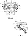
- Fig. 29 shows an alternate embodiment for a retaining feature for maintaining seal assembly 220 within access ports 212 of the elastic access portion 210 utilizing a spring hose clamp 2932.
- the clamp 2932 is held in position and operated with an inner ring 2934 and outer ring 2936.
- the inner ring 2934 holds one end 2932a of the clamp 2932 and another end 2932b of the clamp 2932 is held by the outer ring 2936.
- Rotating the outer ring 2936 and inner ring 2934 in opposing directions will open and close the clamp 2932 and allow for adjustability.
- Fig. 30 shows another embodiment of a retaining feature 3032 wherein a living hinge 3034 is included in a 3032.
- the retaining feature 3032 has ratchet teeth 3042 that mate with opposing ratchet teeth 3046 of the ring 3032 and that once wrapped around an access port 220 will ratchet closed.
- Fig. 31 shows yet another embodiment for the retaining feature including a strap or belt 3132 that could be used to hold access port 220 within the opening 212.
- outward extending pins 3132a mate with holes 3132b of opposing ends of strap to secure 3132 the strap together.
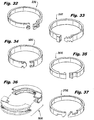
- Figs. 32-37 show varying embodiments of locking mechanisms for straps 3232, 3332, 3432, 3532, 3632, 3732.
- Strap 3232 includes a pin configured to be inserted and slid through slot to lock strap into position.
- Strap 3332 includes a pull and twist design which allows for tightening the strap as needed to hold seal assembly in position.
- Fig. 34 illustrates strap 3432 having one generally arrow shaped end that can be inserted into an opening at an opposing end by press fitting the ends together.
- Figs. 35 and 37 illustrate straps 3532 and 3732 each having hook features with varying orientations.
- Strap 3632, shown in Fig. 36 includes I-beams on opposing ends that snap fit together.
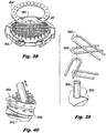
- FIGs. 38-42 alternate designs to the multi-port sub assembly 200 are shown by incorporating stitching underneath the access ports 212. When assembled the stitching is enclosed within the latch assembly 240.
- the stitching includes elastic stitches 3828 in an alternating pattern, a continuous stitch, or multiple layers with alternating gaps.
- each individual elastic string 3828 overlaps in an alternating pattern such that there are no openings or leaks.
- this embodiment includes a circular bottom plate 3822, a top ring plate 3824 and a plurality of posts 3826 along the circumference of the bottom plate 3822 for looping each stitch 3828 around.
- This design can include one more than one layer of weaving to compensate for "cat-eyeing".
- Fig. 41 shows a continuous elastic stitch 4128 design that would be wound in one direction around posts 4126 between a bottom plate 4122 and a top ring 4124.
- Fig. 42 shows a plurality of circular elastic layers 4226a-d where elongated gaps 4228 on each layer 4226a-d are angled with each adjacent layer 4226a-d.
- each layer 4226a-d is manufactured the same, but assembled in different orientations (0, 45, 90, 135 degrees).
- a user inserts surgical instruments through the weave, stitch, or layers to maintain stability of the surgical instruments during a surgical procedure.
- multi-port sub assembly 4300 (shown in Fig. 43 ) includes access ports 4312 with equal heights and a pressure/vacuum port 4318.
- Multi-port assembly 4400 (shown in Fig. 44 ) includes access ports 4412 of varying heights and a trocar port 4418 and multi-port assembly 4600 (shown in Fig. 46 ) includes access ports 4612 and a trocar port 4618.
- Fig. 45 and 47 also show alternate embodiments of attaching the multi-port assemblies 4300, 4400 and 4600 to a wound protector, for example, wound protector 1004 (shown in Fig. 19 ).
- Assemblies 4300, 4400 and 4600 include internal elastic features, for example grooves 4426, 4628 and 4626, which mate with at least one exterior ring, for example ring 1026, on the wound protector. The elastic feature seals the multi-port assembly to the wound protector.
- Figs. 48-50 show an alternate embodiment of a latch assembly 5140 for mating the multi-port assembly 4800 with the wound protector assembly 300.
- Multi-port assembly 2800 includes latch assembly 5040 having a coupler body 5042 with diametrically opposed horizontally aligned spring loaded latches 5043, 5045.
- Each latch 5043, 5045 has a ratchet tooth 5052 at one end, a flexible arm 5056 on the opposing end and a middle portion 5054 therebetween to pivot around.
- the coupler body 5042 has two slots 5064 (only one shown in Fig. 49-51 for clarity) for inserting the ratchet tooth 5052 therein and a groove 5068 for the flexible arm 5056 to mate with.
- a user squeezes flexible arm 5056 and pivots the latches 5043, 5045 outwardly such that ratchet teeth 5052 engage ratchet teeth 322 of retaining ring 312.
- This design also allows the user to reposition the multi-port sub-assembly 4800 rotationally without losing the seal in a similar manner as multi-port sub assembly 200, described in Figs. 1-15 .
- Figs. 51-53 illustrate yet another alternate embodiment of a latch assembly 5140 for mating multi-port assembly 5100 with the wound protector assembly 300.
- Latch assembly 5140 includes a coupler body 5142 with diametrically opposed vertically aligned spring loaded latches 5143, 5145.
- Each latch 5143, 5145 has a ratchet tooth 5152 at one end, a flexible arm 5156 on the opposing end and a middle portion 5154 therebetween to pivot around.
- the coupler body 5142 has an annular groove 5168 for flexible arm 5156 to mate with.
- This embodiment works similar to latch assembly 5040. To operate, a user squeezes flexible arm 5156 and pivots the latches 5143, 5145 outwardly such that ratchet teeth 5152 engage ratchet teeth 322 of retaining ring 312.
- Figs. 54-56 show an alternate embodiment of a latch assembly 5440 for mating the multi-port assembly 200 with the wound protector assembly 300.
- a spring loaded horizontal latch ring 5450 is configured to engage wound protector 300. More specifically, the latch ring 5450 includes a ratchet feature 5452 that can engage ratchet teeth 322 of wound protector 300. In an alternate embodiment, the ratchet feature may also simply mate with the elastic wound protector directly.
- a button 5445 on the latch ring 5450 contains spring 5462 which manipulates the ratchet feature 5452.
- the ratchet feature 5452 is moved outwards (shown in Fig. 56 ) to an open position, and a user can either engage or disengage from the wound protector 300.
- Releasing the spring (shown in Fig. 55 ) returns the ratchet feature to a closed position and maintains the connection between ratchet feature 5452 and ratchet teeth 322.
- This embodiment also allows the user to reposition the top multi-port assembly 200 rotationally without losing the seal.
- Figs. 57-59 show yet another alternate embodiment for a latch assembly 5740.
- a spring loaded hose clamp 5742 engages wound protector assembly 5900.
- wound protector assembly 5900 includes an elastic body 5904 and a proximal ring 5904a that maintains the seal between multi-port assembly 5700 and the wound protector body 5904.
- the hose clamp 5742 is embedded inboard of an inner ring 5736 (shown in Fig. 58 ), which in turn, is positioned inboard of an outer ring 5738.
- the outer ring 5738 mates the latch assembly 5740 to the multi-port sub assembly 5800.
- Each of the inner ring 5736 and outer ring 5738 include a finger tab 5736a, 5738a, respectively, to manipulate the clamp 5742.
- a user squeezes the tabs 5736a, 5738a towards one another (as shown in Fig. 59 ) which compresses the clamp 5742 to loosen the engagement from the wound protector body 5904.
- This design also allows the user to reposition the multi-port assembly 200 rotationally.
- Figs. 60-62 illustrate an alternate embodiment of multi-port sub assembly 6000 and wound protector sub assembly 6100 having a push on design with ratchet feature 6122.
- the elastic access portion 6010 is coupled to a top ring 6012 which has diametrically opposed release pads 6014 and inwardly protruding ratchet teeth 6022 along a bottom circumference thereof.
- the wound protector 6100 has a bottom ring 6132 at a proximal end 6104a of the wound protector body 6104 with ratchet features 6134.
- a user squeezes the release pads 6014 inwards to flex the top ring 6012 and pushes the top ring 6012 over the bottom ring 6132 until ratchet teeth 6022 align with the ratchet features 6134. Releasing the pads 6014 will return the top ring 6012 to a home position and ratchet teeth 6022 of the top ring 6012 will lock with the ratchet features 6134 of the bottom ring 6132.
- the user squeezes the release pads 6014 and rotates the multi-port assembly 6000 until the desired position is reached.
- retaining ring 6412 is part of the multi-port assembly, in contrast to the previous embodiments wherein the retaining ring was part of the wound protector assembly (for example as shown in Figs. 1-15 ).
- a top ring 6432 is coupled to the elastic access portion 6410 and includes a ratchet button 6433.
- the ratchet button 6433 has two flexible hooks 6433a on opposing ends which engage a ratchet feature 6422 of the retaining ring 6412.
- the top ring 6432 further includes downwardly extending flexible tabs 6434 that snap over the ratchet feature 6422 and keep the top ring 6432 and elastic access portion 6410 from disengaging linearly. By pressing the ratchet button 6433 the hooks 6433a flex outwardly and allow rotational movement of the elastic access portion 6410.
- the retaining ring 6412 includes press fit slots 6424 to accept a spring loaded shroud 6452 and a plurality of 90 degree cams slots 6426 for mating with wound protector 6400.
- the shroud 6452 has flexible arms 6454 which attach to the ratchet ring 6412 and bias the shroud 6452 away from the ratchet ring 6412.
- the wound protector 6400 has a bottom ring 6414 at a proximal end 6404a of the wound protector body 6404 without circumferentially arranged perpendicularly extending posts 6414a that mate with the cam slots 6426 of the ratchet ring 6412.
- the shroud 6452 includes a plurality of cross-arms 6456 to engage the posts 6414a of the bottom ring 6414 as the posts 6414a are inserted into the cam slots 6426.
- the posts 6414a of wound protector 6400 migrate through the cam slots 6426 and the shroud 6456 extends over the proximal portion 6404a of the wound protector body 6404 thereby locking the multi-port sub assembly 6300 to the wound protector 6400.
- the user will lift the shroud 6456 away from the wound protector 6400, reverse twist and pull off.
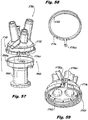
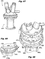
- Figs. 67-69 show yet another alternate embodiment of a multi-port assembly 6700 and wound protector assembly 6800 having a push and twist design with three rotational positions.
- the multi-port assembly 6700 includes an inner ring 6714, and an outer ring 6716 attached thereto.
- the inner ring 6714 has a plurality of flexible arms 6722 (shown in Fig. 69 ) with a ratchet tooth 6724 on one end.
- Each ratchet tooth 6724 includes a perpendicularly extending post 6724a that engages a corresponding hole 6718 of outer ring 6716.
- the inner ring 6714 also has a plurality of 90 degree locking tabs 6732 (shown in Fig. 68 ) to lock the multi-port assembly 6700 to the wound protector sub assembly 6800.
- the wound protector sub-assembly 6800 has a proximal flange 6812 extending from a proximal portion 6804a of the wound protector body 6404 that includes a plurality of elongated slots 6814 to accept the inner ring locking tabs 6732, and openings 6818 to accept the ratchet tooth 6724 of the inner ring 6714 therein.
- the openings 6818 are positioned as a set of three between the elongated slots 6814.
- a user positions the locking tabs 6732 of the inner ring 6714 over the elongated slots 6814 of the proximal flange 6812 and pushes downwardly and twists.
- the 90 degree shape of the locking tab 6732 will fit into a keyed portion 6814a of elongated slot 6814.
- the twisting motion locks the multi-port sub assembly 6700 to the wound protector 6800 (shown in Fig. 69 ).
- the elongated slot 6814 allows the user to continue to twist the multi-port sub assembly 6700 to three rotational positions corresponding to the openings 6818 along the proximal flange 6812.
- the user will lift the outer ring 6716 which will release the ratchet teeth 6724 out of the openings 6818 and reverse twist to migrate the locking tabs 6732 back to the keyed portion 6814a of the elongated slots 6814.
- the multi-port assembly 6700 can then be pulled away and off of the wound protector sub assembly 6800.
- Figs. 70-72 illustrate another alternate embodiment of a multi-port assembly 7000 and a wound protector sub assembly 7100.
- the multi-port assembly includes a static ring 7014 engaged with a dynamic ring 7016.
- the static ring 7014 has mating pockets 7022 to accept ratchet teeth 7032 of the dynamic ring 7016 therein (shown in Fig. 72 ).
- the dynamic ring 7016 also has flexible tabs 7034 to bias the ratchet teeth 7032 into the static ring 7014.
- the dynamic ring 7016 includes an internal thread 7036 and flexible locking features 7038 (shown in Fig. 71 ) to couple the multi-port assembly 7000 to the wound protector assembly 7100 and prevent linear movement therebetween.
- the wound protector sub assembly 7100 includes posts 7102 and slots 7106 circumferentially spaced around a proximal ring 7112 at a proximal end 7104a of wound protector body 7104.
- a user screws the multi-port assembly 7000 over the posts 7102 on the proximal ring 7112 until the flexible locking tabs 7038 snap into mating slots 7106 on the proximal ring 7112.
- the top multi-port assembly 7000 is now locked onto the wound protector 7100.
- the user pushes the static ring 7014 onto the dynamic ring 7016, which will flex the tabs 7034 of the dynamic ring and move the static ring slot/pockets 7022 off the dynamic ring ratchet teeth 7032 and allow rotation.
- the user flexes the locking feature 7038 on the dynamic ring 7016 to disengage the slot 7106 of the wound protector 7100 and twists the multi-port sub assembly to unscrew.
- Fig. 73 illustrates an alternate design for assembling a multi-port assembly 7302 to the wound protector 7350.
- This embodiment includes an assembly aid 7300 that engages the elastic access portion 7310 of the multi-port assembly 7302.
- the assembly aid 7300 has four flexible arms 7312 which are attached together with a coupler 7332 that acts as a pivot for each of the flexible arms 7312.
- Each of the flexible arms 7312 has a first end 7312a that engages a corresponding slot 7321 of the elastic access portion 7310.
- a rotational disc 7342 with openings for the flexible arms 7312 can be used to squeeze and pivot the flex arms 7312.
- Figs. 74-75 illustrate an alternate embodiment for a wound protector sub assembly 7400 having an adjustable length.
- the wound protector assembly 7400 includes a plurality of telescoping sections 7404a-c biased closed with springs 7406b-c.
- the springs 7408b-c are held in position by a flange 7406b-c of each telescoping section.
- the flange of the outermost telescoping section 7406a anchors into the patient and extends through the incision to allow the multi-port sub assembly 200 to attach with retaining ring 312. Rotation of each telescoping section 7404a-c allows for adjusting the length of the wound protector assembly 7400.
- Fig. 76 illustrates an alternate embodiment for extending the length of a wound protector assembly 7600.
- an external thread 7612 positioned on a proximal portion 7604a of wound protector body 7604 is configured to engage an internal thread 7614 of a proximal ring 7622.
- the proximal ring 7622 can be lifted or lowered simply by twisting thereby adjusting the height of the multi-port sub assembly 200 as needed.
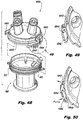
- Fig. 77 shows another embodiment of a multi-port sub assembly and wound protector sub assembly which is particularly adapted for specimen removal.
- the device includes an "S" shaped duckbill seal 7720.
- a similar type of seal structure is disclosed for example in U.S. Patent Application Publication No. 2013/0012782 .
- multi-port sub assembly 7900 includes a top ring 7926 with a plurality of circumferentially spaced apart openings therethrough.
- Latch assembly 7940 similar to latch assembly 240, includes a plurality of circumferentially space upwardly extending flexible tabs 7940a designed and configured to snap fit into corresponding openings of the top ring.
- a flange 7914 on the elastic access portion 7910 of the multi-port end cap 7910 is squeezed between top ring 7926 and latch assembly 7940 securing the multi-port end cap therebetween.
- Retaining ring 8012 similar to retaining ring 312, includes ratchet features 322 that engage with ratchet teeth 252 of the latch assembly 7940.
- a smoke evacuation port 8048 can be inserted into retaining ring 8012 with pressure sensing port 8046.
- the air seal port 8042 includes an annular groove 8062 for mating with flex tabs 8064 of the retaining ring 8012.
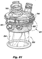
- O-ring seals 8043, 8047 are positioned between the air seal port 8042 and pressure sensing port 8046, respectively, and the retaining ring 8012 to maintain the seal during a surgical procedure (shown best in Fig. 81 ).
- Wound protector assembly 8000 includes a bottom ring 8018 having circumferentially spaced openings therethrough that allow flexible tabs 8012a of retaining ring 8012 to be snap fitted therein.
- An adapter 8034 is secured and held into position between the retaining ring 8012 and bottom ring 8018. Both the adapter 8034 and bottom ring 8318 are dimensioned and configured to allow air seal port 8042 and pressure sensing port 8046 to easily engage with the retaining ring 8012.
- the adapter 8034 is a proximal portion of the wound protector body 8004, similar to wound protector 304, configured for insertion into a patient.
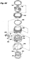
- Figs. 81-83 illustrate an alternate embodiment of wound protector assembly 8300.
- Wound protector assembly 8300 is coupled to multi-port sub assembly 7900.
- adapter is in the form of a seal 8332 positioned between retaining ring 8012 and bottom ring 8318. Both the seal 8332 and bottom ring 8318 are dimensioned and configured to allow air seal port 8042 and pressure sensing port 8046 to easily engage with the retaining ring 8012.
- Seal 8332 mates with a proximal portion 8304a of wound protector body 8304, similar to wound protector 1004. Bottom ring slides around seal 8332 and aligns with an annular flange or groove to further maintain seal in position. Referring to Figs. 84 and 85 two seal configurations are shown capable of use with wound protector assembly 8300. Seal 8332 illustrates a duck bill design and seal 8334 illustrates a generally S shape.
Landscapes
- Health & Medical Sciences (AREA)
- Life Sciences & Earth Sciences (AREA)
- Surgery (AREA)
- Public Health (AREA)
- Animal Behavior & Ethology (AREA)
- Engineering & Computer Science (AREA)
- Biomedical Technology (AREA)
- Heart & Thoracic Surgery (AREA)
- Veterinary Medicine (AREA)
- General Health & Medical Sciences (AREA)
- Nuclear Medicine, Radiotherapy & Molecular Imaging (AREA)
- Molecular Biology (AREA)
- Medical Informatics (AREA)
- Pathology (AREA)
- Anesthesiology (AREA)
- Hematology (AREA)
- Surgical Instruments (AREA)
Claims (15)
- Zugangsvorrichtung (100) für chirurgische Eingriffe, umfassend:- einen länglichen rohrförmigen Körperabschnitt (304), der eine Längsachse definiert und zum Einführen durch eine natürliche Öffnung eines Körperlumens oder durch einen einzelnen Schnitt in die Wand der Bauchhöhle eines Patienten eingerichtet ist;- eine Mehrfachanschluss-Endkappe (200), die funktionsfähig mit einem proximalen Endabschnitt (304a) des rohrförmigen Körperabschnitts (304) verbunden ist und eine Mehrzahl von separaten Zugangsanschlüssen (212) umfasst, um die Einführung einzelner chirurgischer Instrumente (104) in das Körperlumen oder die Bauchhöhle des Patienten aufzunehmen; und- eine Kupplung zum funktionsfähigen Verbinden der Mehrfachanschluss-Endkappe (200) mit dem proximalen Endabschnitt (304a) des rohrförmigen Körperabschnitts (304);- dadurch gekennzeichnet, dass- die Kupplung einen Ratschenring (312) am rohrförmigen Körperabschnitt (304) und eine Verriegelungsanordnung (240) an der Mehrfachanschluss-Endkappe (200) umfasst, wobei die Verriegelungsanordnung gegenüberliegende Verriegelungen (246, 248) umfasst, die jeweils einen halbkreisförmigen Abschnitt mit radial nach innen gerichteten Zähnen (252) aufweist, die mit dem Ratschenring (312) zusammenpassen, um eine axiale Drehung der Mehrfachanschluss-Endkappe (200) relativ zum rohrförmigen Körperabschnitt (304) zu verhindern, und die sich vom Ratschenring (312) lösen, um eine axiale Drehung der Mehrfachanschluss-Endkappe (200) relativ zum rohrförmigen Körperabschnitt (304) zu ermöglichen, wenn die Verriegelungen (246, 248) radial nach innen zusammengedrückt werden.
- Zugangsvorrichtung (100) für chirurgische Eingriffe nach Anspruch 1, wobei die Kupplung einen kreisförmigen Körper (242) umfasst, der mit der Mehrfachanschluss-Endkappe (200) verbunden ist und den Ratschenring (312) umgibt.
- Zugangsvorrichtung (100) für chirurgische Eingriffe nach Anspruch 2, wobei die Verriegelungen (246, 248) jeweils parallele Verlängerungen (246a, 246b, 248a, 248b) aufweisen, die sich von den halbkreisförmigen Abschnitten davon erstrecken, und zum Einrasten gegenüberliegender Schlitze (247) in den kreisförmigen Körper (242) eingerichtet sind.
- Zugangsvorrichtung (100) für chirurgische Eingriffe nach Anspruch 3, wobei die Kupplung federbelastete Druckknöpfe (243, 245) umfasst, die mit den Verriegelungen (246, 248) zum selektiven Zusammendrücken der halbkreisförmigen Abschnitte der Verriegelungen (246, 248) radial nach innen verbunden sind.
- Zugangsvorrichtung für chirurgische Eingriffe nach Anspruch 1, wobei der längliche rohrförmige Körperabschnitt (304) ein laparoskopischer Wundschutz ist.
- Zugangsvorrichtung (100) für chirurgische Eingriffe nach Anspruch 1, wobei die Kupplung einen Verbinder (342) für eine Druckgasleitung (106) und einen Verbinder (346) für eine Druckerfassungsleitung (108) umfasst.
- Zugangsvorrichtung für chirurgische Eingriffe nach Anspruch 6, wobei der rohrförmige Körperabschnitt (304) ein Lumen umfasst, das sich von der Druckerfassungsleitung (108) durch eine Bodenfläche davon erstreckt.
- Zugangsvorrichtung (100) für chirurgische Eingriffe nach Anspruch 1, wobei die Endkappe (200) einen Verbinder für eine Druckgasleitung (106) umfasst und der rohrförmige Körperabschnitt einen Verbinder für eine Druckerfassungsleitung (108) umfasst.
- Zugangsvorrichtung (100) für chirurgische Eingriffe nach Anspruch 1, wobei eine Dichtungsanordnung (220) funktionsfähig mit jedem der Zugangsanschlüssen (212) der Endkappe (200) verbunden ist.
- Zugangsvorrichtung (100) für chirurgische Eingriffe nach Anspruch 8, wobei jede Dichtungsanordnung (220) eine Hauptöffnungsdichtung (224) und eine sekundäre Entenschnabel-Dichtung (226) umfasst.
- Zugangsvorrichtung (100) für chirurgische Eingriffe nach Anspruch 9, wobei jede Dichtungsanordnung (220) in jedem Zugangsanschluss (212) mit einem externen Halteelement (214) gesichert ist.
- Zugangsvorrichtung (100) für chirurgische Eingriffe nach Anspruch 11, wobei das Halteelement (214) einen Verriegelungsmechanismus umfasst, der aus der Gruppe ausgewählt wird, die aus Haken, Ratschenzähnen, Stiften und Löchern, Stiften und Schlitzen, I-Trägern und Zieh- und Drehverbindungen besteht.
- Zugangsvorrichtung (100) für chirurgische Eingriffe nach Anspruch 1, wobei die Mehrfachanschluss-Endkappe (4400, 4600) einen Trokaranschluss (4418, 4618) umfasst.
- Zugangsvorrichtung (100) für chirurgische Eingriffe nach Anspruch 1, wobei die Mehrfachanschluss-Endkappe (200) eine Webschicht umfasst, die eingerichtet ist, um das chirurgische Instrument (104) dadurch zu sichern.
- Zugangsvorrichtung (100) für chirurgische Eingriffe nach Anspruch 1, die ferner eine Montagehilfe (7300) zum Eingreifen der Mehrfachanschlusskappe (200) in den rohrförmigen Körperabschnitt (304) aufweist oder wobei der rohrförmige Körperabschnitt (304) eine einstellbare Länge aufweist.
Applications Claiming Priority (2)
| Application Number | Priority Date | Filing Date | Title |
|---|---|---|---|
| US201562212776P | 2015-09-01 | 2015-09-01 | |
| PCT/US2016/049613 WO2017040602A1 (en) | 2015-09-01 | 2016-08-31 | Multi-port access device for minimally invasive surgical procedures |
Publications (2)
| Publication Number | Publication Date |
|---|---|
| EP3346934A1 EP3346934A1 (de) | 2018-07-18 |
| EP3346934B1 true EP3346934B1 (de) | 2020-05-13 |
Family
ID=56889245
Family Applications (1)
| Application Number | Title | Priority Date | Filing Date |
|---|---|---|---|
| EP16763171.2A Active EP3346934B1 (de) | 2015-09-01 | 2016-08-31 | Multiport-zugangsvorrichtung für minimal-invasive chirurgische eingriffe |
Country Status (9)
| Country | Link |
|---|---|
| US (2) | US10076358B2 (de) |
| EP (1) | EP3346934B1 (de) |
| JP (1) | JP6634513B2 (de) |
| KR (1) | KR102211559B1 (de) |
| CN (1) | CN108430354B (de) |
| AU (1) | AU2016315760B2 (de) |
| CA (1) | CA2997215C (de) |
| ES (1) | ES2824160T3 (de) |
| WO (1) | WO2017040602A1 (de) |
Families Citing this family (39)
| Publication number | Priority date | Publication date | Assignee | Title |
|---|---|---|---|---|
| US8961406B2 (en) * | 2009-03-06 | 2015-02-24 | Ethicon Endo-Surgery, Inc. | Surgical access devices and methods providing seal movement in predefined movement regions |
| US11607507B2 (en) * | 2015-07-07 | 2023-03-21 | Lexion Medical, Llc | Method and system for measuring pressure in a body cavity |
| USD810290S1 (en) * | 2016-01-29 | 2018-02-13 | Medovex Corp. | Surgical portal driver |
| AU2017324450B2 (en) * | 2016-09-12 | 2022-09-29 | Applied Medical Resources Corporation | Surgical robotic access system for irregularly shaped robotic actuators and associated robotic surgical instruments |
| DE102017104083B3 (de) * | 2017-02-27 | 2017-11-02 | Leica Camera Ag | Schutzkappe |
| US10966752B2 (en) * | 2017-03-08 | 2021-04-06 | Conmed Corporation | Single lumen gas sealed trocar for maintaining stable cavity pressure without allowing instrument access therethrough during endoscopic surgical procedures |
| US10869691B2 (en) | 2017-03-08 | 2020-12-22 | Conmed Corporation | Flexible single lumen gas sealed access port for use during robotically assisted endoscopic surgical procedures |
| US11717664B2 (en) | 2017-08-08 | 2023-08-08 | Merit Medical Systems, Inc. | Hemostasis valves having multiple sealable openings |
| CN111225596B (zh) | 2017-08-23 | 2022-05-31 | 麦米克创新外科有限公司 | 用于阴道途径的工具与方法 |
| US10405884B2 (en) * | 2017-10-23 | 2019-09-10 | Conmed Corporation | Devices for performing minimally invasive surgery having rotating multiport access |
| US10413324B2 (en) * | 2017-10-23 | 2019-09-17 | Conmed Corporation | Devices for performing minimally invasive surgery having foam support housing |
| US10463396B2 (en) * | 2017-10-23 | 2019-11-05 | Conmed Corporation | Devices for performing minimally invasive surgery having bellows support housing |
| WO2019148346A1 (zh) * | 2018-01-31 | 2019-08-08 | 三雷斯医疗科技(深圳)有限公司 | 一种手术通路系统 |
| KR102040079B1 (ko) * | 2018-04-02 | 2019-11-04 | 남병욱 | 의료용 가이드 포트를 위한 밀폐 캡 및 이를 가진 가이드 포트 |
| KR102102531B1 (ko) * | 2018-05-17 | 2020-04-21 | 인제대학교 산학협력단 | 복강경 수술용 트로카 |
| US11273270B2 (en) * | 2018-06-22 | 2022-03-15 | Conmed Corporation | Surgical gas delivery system with remote gaseous sealing module and gas sealed sleeve for accessing a surgical cavity |
| US10987135B2 (en) * | 2018-07-13 | 2021-04-27 | Ethicon Llc | Seal cartridge design for trocar assemblies |
| US10932818B2 (en) * | 2019-05-07 | 2021-03-02 | Covidien Lp | Removable seal assembly and access system including the same |
| US11426203B2 (en) | 2019-05-23 | 2022-08-30 | Covidien Lp | Tissue guards and systems incorporating the same for tissue specimen removal procedures and other surgical procedures |
| KR102261991B1 (ko) * | 2019-06-05 | 2021-06-08 | 라파코리아(주) | 밀폐 기능 및 슬립 방지 기능이 향상된 가이드 포트 |
| CN110353783A (zh) * | 2019-08-15 | 2019-10-22 | 上海市肺科医院 | 一种柔性胸腔积液引流穿刺装置 |
| US11278317B2 (en) | 2019-08-28 | 2022-03-22 | Covidien Lp | Surgical access devices and systems including smoke evacuation |
| KR102278476B1 (ko) * | 2019-11-12 | 2021-07-15 | 김기성 | 복강경 수술용 트로카 시스템 |
| KR102445741B1 (ko) * | 2019-11-18 | 2022-09-20 | 박상민 | 개폐 방식의 포트 덮개 및 이를 가진 의료용 포트 |
| US11058459B2 (en) * | 2019-12-12 | 2021-07-13 | Covidien Lp | Two-piece cutting guard with evacuation ports |
| US11116488B2 (en) | 2019-12-20 | 2021-09-14 | Covidien Lp | Tissue guard for tissue removal and other surgical procedures |
| CN111134857B (zh) * | 2020-01-10 | 2020-12-01 | 武汉大学 | 一种开合式可固定于腔镜切口保护套的切口分区稳定器 |
| KR102352882B1 (ko) * | 2020-02-05 | 2022-01-18 | 주식회사 오렌지메딕스 | 최소침습 수술용 싱글포트 |
| US11484337B2 (en) * | 2020-02-06 | 2022-11-01 | Covidien Lp | Surgical access device including anchor with rachet mechanism |
| US11690648B2 (en) | 2020-03-03 | 2023-07-04 | Covidien Lp | Surgical access device and method for using the same |
| US11583314B2 (en) | 2020-03-03 | 2023-02-21 | Covidien Lp | Surgical access device and method for using the same |
| JP7414611B2 (ja) | 2020-03-26 | 2024-01-16 | 株式会社メディカロイド | ロボット手術支援装置、処理方法、及びプログラム |
| US11529191B2 (en) | 2020-05-26 | 2022-12-20 | Covidien Lp | Auxiliary electrosurgical return via cutting guard |
| US11627988B2 (en) | 2020-07-14 | 2023-04-18 | Covidien Lp | Snap-fit cutting guard |
| KR102487818B1 (ko) * | 2020-07-30 | 2023-01-12 | 서지윤 | 수술도구 가이드포트용 도구진입관 |
| US11931067B2 (en) | 2020-08-15 | 2024-03-19 | Covidien Lp | Insertable cutting guards |
| US11534258B2 (en) * | 2020-08-26 | 2022-12-27 | Covidien Lp | Cutting guard |
| CN112190315B (zh) * | 2020-10-10 | 2021-07-06 | 安徽医科大学第一附属医院 | 一种腔镜手术用通道固定支架 |
| CN114431941B (zh) * | 2022-04-08 | 2022-07-01 | 江苏人冠医疗科技有限公司 | 一种气腹机用循环排烟功能单孔多通道穿刺器 |
Family Cites Families (27)
| Publication number | Priority date | Publication date | Assignee | Title |
|---|---|---|---|---|
| US3612323A (en) * | 1969-09-25 | 1971-10-12 | Dell M Malick | Safety closure |
| US4752013A (en) * | 1987-11-27 | 1988-06-21 | Miller Jack V | Tamper-evident child-resistant cap and bottle with axial locking means |
| US5545179A (en) * | 1995-07-21 | 1996-08-13 | Ethicon Endo-Surgery, Inc. | Endoscopic access assembly |
| JP4647727B2 (ja) * | 1997-05-02 | 2011-03-09 | ユナイテッド ステイツ サージカル コーポレイション | トロカール密封装置 |
| EP1849489B1 (de) * | 1997-05-02 | 2009-10-07 | United States Surgical Corporation | Kanülenanordnung |
| US5918752A (en) * | 1998-01-14 | 1999-07-06 | Owens-Illinois Closure Inc. | Tamper-evident squeeze-and-turn child-resistant closure |
| US7559893B2 (en) | 1998-12-01 | 2009-07-14 | Atropos Limited | Wound retractor device |
| US7854724B2 (en) | 2003-04-08 | 2010-12-21 | Surgiquest, Inc. | Trocar assembly with pneumatic sealing |
| WO2005097019A2 (en) * | 2004-04-05 | 2005-10-20 | Tyco Healthcare Group Lp | Surgical hand access apparatus |
| US8251900B2 (en) * | 2009-03-06 | 2012-08-28 | Ethicon Endo-Surgery, Inc. | Surgical access devices and methods providing seal movement in predefined paths |
| US8430811B2 (en) * | 2008-09-30 | 2013-04-30 | Ethicon Endo-Surgery, Inc. | Multiple port surgical access device |
| US8926506B2 (en) * | 2009-03-06 | 2015-01-06 | Ethicon Endo-Surgery, Inc. | Methods and devices for providing access into a body cavity |
| US20080011307A1 (en) * | 2006-07-12 | 2008-01-17 | Beckman Andrew T | Hand assisted laparoscopic device |
| US8795223B2 (en) | 2011-03-08 | 2014-08-05 | Surgiquest, Inc. | Trocar assembly with pneumatic sealing |
| US8070770B2 (en) * | 2007-02-22 | 2011-12-06 | Ethicon Endo-Surgery, Inc. | Iris valve with novel locking mechanism |
| US7766822B2 (en) * | 2007-03-06 | 2010-08-03 | Ethicon Endo Surgery, Inc. | Hand assisted laparoscopic seal assembly with a ratcheting mechanism |
| US8657740B2 (en) | 2007-06-05 | 2014-02-25 | Atropos Limited | Instrument access device |
| EP2349033B1 (de) | 2008-10-10 | 2020-04-08 | Surgiquest, Inc. | Chirurgische zugangsvorrichtungen mit niedrigem profil und verankerung |
| EP2341849B1 (de) * | 2008-10-10 | 2019-12-18 | SurgiQuest, Incorporated | System für verbesserte gasrückführung in chirurgischen trokaren mit pneumatischer versiegelung |
| US20110028793A1 (en) * | 2009-07-30 | 2011-02-03 | Ethicon Endo-Surgery, Inc. | Methods and devices for providing access into a body cavity |
| US20110028794A1 (en) * | 2009-07-30 | 2011-02-03 | Ethicon Endo-Surgery, Inc. | Methods and devices for providing access into a body cavity |
| WO2011033495A1 (en) * | 2009-09-17 | 2011-03-24 | Atropos Limited | An instrument access device |
| US8808248B2 (en) * | 2009-10-15 | 2014-08-19 | Biosense Webster, Inc. | Catheter sheath introducer with rotational lock |
| KR101022754B1 (ko) * | 2010-08-24 | 2011-03-17 | 류성엽 | 운드 리트랙터를 겸비한 멀티채널 트로카 |
| AU2011308636B2 (en) * | 2010-10-01 | 2015-06-04 | Applied Medical Resources Corporation | Surgical access port system |
| CN102727262B (zh) * | 2012-05-23 | 2014-08-27 | 王小军 | 腹腔镜手术单切口密封装置 |
| JP6407977B2 (ja) * | 2013-09-20 | 2018-10-17 | アプライド メディカル リソーシーズ コーポレイション | 生まれつきの開口用のアクセス器具 |
-
2016
- 2016-08-31 CN CN201680063413.1A patent/CN108430354B/zh active Active
- 2016-08-31 JP JP2018511425A patent/JP6634513B2/ja active Active
- 2016-08-31 US US15/253,255 patent/US10076358B2/en active Active
- 2016-08-31 EP EP16763171.2A patent/EP3346934B1/de active Active
- 2016-08-31 KR KR1020187007408A patent/KR102211559B1/ko active IP Right Grant
- 2016-08-31 ES ES16763171T patent/ES2824160T3/es active Active
- 2016-08-31 AU AU2016315760A patent/AU2016315760B2/en active Active
- 2016-08-31 CA CA2997215A patent/CA2997215C/en active Active
- 2016-08-31 WO PCT/US2016/049613 patent/WO2017040602A1/en active Application Filing
-
2018
- 2018-08-14 US US16/102,933 patent/US10893886B2/en active Active
Non-Patent Citations (1)
| Title |
|---|
| None * |
Also Published As
| Publication number | Publication date |
|---|---|
| CA2997215C (en) | 2020-01-07 |
| CA2997215A1 (en) | 2017-03-09 |
| US20180353205A1 (en) | 2018-12-13 |
| US10076358B2 (en) | 2018-09-18 |
| EP3346934A1 (de) | 2018-07-18 |
| KR102211559B1 (ko) | 2021-02-04 |
| CN108430354A (zh) | 2018-08-21 |
| US20170056064A1 (en) | 2017-03-02 |
| WO2017040602A1 (en) | 2017-03-09 |
| CN108430354B (zh) | 2021-05-11 |
| AU2016315760B2 (en) | 2020-08-13 |
| ES2824160T3 (es) | 2021-05-11 |
| US10893886B2 (en) | 2021-01-19 |
| JP2018526112A (ja) | 2018-09-13 |
| KR20180048714A (ko) | 2018-05-10 |
| AU2016315760A1 (en) | 2018-03-29 |
| JP6634513B2 (ja) | 2020-01-22 |
Similar Documents
| Publication | Publication Date | Title |
|---|---|---|
| EP3346934B1 (de) | Multiport-zugangsvorrichtung für minimal-invasive chirurgische eingriffe | |
| US11806498B2 (en) | Coupling devices for tube sets used with surgical gas delivery systems | |
| US20120010569A1 (en) | Access device with twist locking removable cap | |
| AU2005231485B2 (en) | Surgical hand access apparatus | |
| US20130172681A1 (en) | Wound protector with reinforced ring | |
| JP2018504197A (ja) | カニューレのシール | |
| KR20200065083A (ko) | 벨로우즈 지지 하우징을 갖는 최소 침습성 수술 수행 장치 | |
| US20100036323A1 (en) | Flexible cannula with seal | |
| US11432843B2 (en) | Centering mechanisms for a surgical access assembly |
Legal Events
| Date | Code | Title | Description |
|---|---|---|---|
| STAA | Information on the status of an ep patent application or granted ep patent |
Free format text: STATUS: THE INTERNATIONAL PUBLICATION HAS BEEN MADE |
|
| PUAI | Public reference made under article 153(3) epc to a published international application that has entered the european phase |
Free format text: ORIGINAL CODE: 0009012 |
|
| STAA | Information on the status of an ep patent application or granted ep patent |
Free format text: STATUS: REQUEST FOR EXAMINATION WAS MADE |
|
| 17P | Request for examination filed |
Effective date: 20180309 |
|
| AK | Designated contracting states |
Kind code of ref document: A1 Designated state(s): AL AT BE BG CH CY CZ DE DK EE ES FI FR GB GR HR HU IE IS IT LI LT LU LV MC MK MT NL NO PL PT RO RS SE SI SK SM TR |
|
| AX | Request for extension of the european patent |
Extension state: BA ME |
|
| DAV | Request for validation of the european patent (deleted) | ||
| DAX | Request for extension of the european patent (deleted) | ||
| GRAP | Despatch of communication of intention to grant a patent |
Free format text: ORIGINAL CODE: EPIDOSNIGR1 |
|
| STAA | Information on the status of an ep patent application or granted ep patent |
Free format text: STATUS: GRANT OF PATENT IS INTENDED |
|
| INTG | Intention to grant announced |
Effective date: 20191216 |
|
| GRAS | Grant fee paid |
Free format text: ORIGINAL CODE: EPIDOSNIGR3 |
|
| GRAA | (expected) grant |
Free format text: ORIGINAL CODE: 0009210 |
|
| STAA | Information on the status of an ep patent application or granted ep patent |
Free format text: STATUS: THE PATENT HAS BEEN GRANTED |
|
| AK | Designated contracting states |
Kind code of ref document: B1 Designated state(s): AL AT BE BG CH CY CZ DE DK EE ES FI FR GB GR HR HU IE IS IT LI LT LU LV MC MK MT NL NO PL PT RO RS SE SI SK SM TR |
|
| REG | Reference to a national code |
Ref country code: GB Ref legal event code: FG4D |
|
| REG | Reference to a national code |
Ref country code: CH Ref legal event code: EP |
|
| REG | Reference to a national code |
Ref country code: DE Ref legal event code: R096 Ref document number: 602016036416 Country of ref document: DE |
|
| REG | Reference to a national code |
Ref country code: AT Ref legal event code: REF Ref document number: 1269219 Country of ref document: AT Kind code of ref document: T Effective date: 20200615 |
|
| REG | Reference to a national code |
Ref country code: LT Ref legal event code: MG4D |
|
| REG | Reference to a national code |
Ref country code: NL Ref legal event code: MP Effective date: 20200513 |
|
| PG25 | Lapsed in a contracting state [announced via postgrant information from national office to epo] |
Ref country code: GR Free format text: LAPSE BECAUSE OF FAILURE TO SUBMIT A TRANSLATION OF THE DESCRIPTION OR TO PAY THE FEE WITHIN THE PRESCRIBED TIME-LIMIT Effective date: 20200814 Ref country code: NO Free format text: LAPSE BECAUSE OF FAILURE TO SUBMIT A TRANSLATION OF THE DESCRIPTION OR TO PAY THE FEE WITHIN THE PRESCRIBED TIME-LIMIT Effective date: 20200813 Ref country code: FI Free format text: LAPSE BECAUSE OF FAILURE TO SUBMIT A TRANSLATION OF THE DESCRIPTION OR TO PAY THE FEE WITHIN THE PRESCRIBED TIME-LIMIT Effective date: 20200513 Ref country code: PT Free format text: LAPSE BECAUSE OF FAILURE TO SUBMIT A TRANSLATION OF THE DESCRIPTION OR TO PAY THE FEE WITHIN THE PRESCRIBED TIME-LIMIT Effective date: 20200914 Ref country code: LT Free format text: LAPSE BECAUSE OF FAILURE TO SUBMIT A TRANSLATION OF THE DESCRIPTION OR TO PAY THE FEE WITHIN THE PRESCRIBED TIME-LIMIT Effective date: 20200513 Ref country code: IS Free format text: LAPSE BECAUSE OF FAILURE TO SUBMIT A TRANSLATION OF THE DESCRIPTION OR TO PAY THE FEE WITHIN THE PRESCRIBED TIME-LIMIT Effective date: 20200913 Ref country code: SE Free format text: LAPSE BECAUSE OF FAILURE TO SUBMIT A TRANSLATION OF THE DESCRIPTION OR TO PAY THE FEE WITHIN THE PRESCRIBED TIME-LIMIT Effective date: 20200513 |
|
| PG25 | Lapsed in a contracting state [announced via postgrant information from national office to epo] |
Ref country code: HR Free format text: LAPSE BECAUSE OF FAILURE TO SUBMIT A TRANSLATION OF THE DESCRIPTION OR TO PAY THE FEE WITHIN THE PRESCRIBED TIME-LIMIT Effective date: 20200513 Ref country code: LV Free format text: LAPSE BECAUSE OF FAILURE TO SUBMIT A TRANSLATION OF THE DESCRIPTION OR TO PAY THE FEE WITHIN THE PRESCRIBED TIME-LIMIT Effective date: 20200513 Ref country code: BG Free format text: LAPSE BECAUSE OF FAILURE TO SUBMIT A TRANSLATION OF THE DESCRIPTION OR TO PAY THE FEE WITHIN THE PRESCRIBED TIME-LIMIT Effective date: 20200813 Ref country code: RS Free format text: LAPSE BECAUSE OF FAILURE TO SUBMIT A TRANSLATION OF THE DESCRIPTION OR TO PAY THE FEE WITHIN THE PRESCRIBED TIME-LIMIT Effective date: 20200513 |
|
| REG | Reference to a national code |
Ref country code: AT Ref legal event code: MK05 Ref document number: 1269219 Country of ref document: AT Kind code of ref document: T Effective date: 20200513 |
|
| PG25 | Lapsed in a contracting state [announced via postgrant information from national office to epo] |
Ref country code: AL Free format text: LAPSE BECAUSE OF FAILURE TO SUBMIT A TRANSLATION OF THE DESCRIPTION OR TO PAY THE FEE WITHIN THE PRESCRIBED TIME-LIMIT Effective date: 20200513 Ref country code: NL Free format text: LAPSE BECAUSE OF FAILURE TO SUBMIT A TRANSLATION OF THE DESCRIPTION OR TO PAY THE FEE WITHIN THE PRESCRIBED TIME-LIMIT Effective date: 20200513 |
|
| PG25 | Lapsed in a contracting state [announced via postgrant information from national office to epo] |
Ref country code: AT Free format text: LAPSE BECAUSE OF FAILURE TO SUBMIT A TRANSLATION OF THE DESCRIPTION OR TO PAY THE FEE WITHIN THE PRESCRIBED TIME-LIMIT Effective date: 20200513 Ref country code: CZ Free format text: LAPSE BECAUSE OF FAILURE TO SUBMIT A TRANSLATION OF THE DESCRIPTION OR TO PAY THE FEE WITHIN THE PRESCRIBED TIME-LIMIT Effective date: 20200513 Ref country code: RO Free format text: LAPSE BECAUSE OF FAILURE TO SUBMIT A TRANSLATION OF THE DESCRIPTION OR TO PAY THE FEE WITHIN THE PRESCRIBED TIME-LIMIT Effective date: 20200513 Ref country code: EE Free format text: LAPSE BECAUSE OF FAILURE TO SUBMIT A TRANSLATION OF THE DESCRIPTION OR TO PAY THE FEE WITHIN THE PRESCRIBED TIME-LIMIT Effective date: 20200513 Ref country code: SM Free format text: LAPSE BECAUSE OF FAILURE TO SUBMIT A TRANSLATION OF THE DESCRIPTION OR TO PAY THE FEE WITHIN THE PRESCRIBED TIME-LIMIT Effective date: 20200513 Ref country code: DK Free format text: LAPSE BECAUSE OF FAILURE TO SUBMIT A TRANSLATION OF THE DESCRIPTION OR TO PAY THE FEE WITHIN THE PRESCRIBED TIME-LIMIT Effective date: 20200513 |
|
| REG | Reference to a national code |
Ref country code: DE Ref legal event code: R097 Ref document number: 602016036416 Country of ref document: DE |
|
| PG25 | Lapsed in a contracting state [announced via postgrant information from national office to epo] |
Ref country code: SK Free format text: LAPSE BECAUSE OF FAILURE TO SUBMIT A TRANSLATION OF THE DESCRIPTION OR TO PAY THE FEE WITHIN THE PRESCRIBED TIME-LIMIT Effective date: 20200513 Ref country code: PL Free format text: LAPSE BECAUSE OF FAILURE TO SUBMIT A TRANSLATION OF THE DESCRIPTION OR TO PAY THE FEE WITHIN THE PRESCRIBED TIME-LIMIT Effective date: 20200513 |
|
| PLBE | No opposition filed within time limit |
Free format text: ORIGINAL CODE: 0009261 |
|
| STAA | Information on the status of an ep patent application or granted ep patent |
Free format text: STATUS: NO OPPOSITION FILED WITHIN TIME LIMIT |
|
| PG25 | Lapsed in a contracting state [announced via postgrant information from national office to epo] |
Ref country code: MC Free format text: LAPSE BECAUSE OF FAILURE TO SUBMIT A TRANSLATION OF THE DESCRIPTION OR TO PAY THE FEE WITHIN THE PRESCRIBED TIME-LIMIT Effective date: 20200513 |
|
| REG | Reference to a national code |
Ref country code: CH Ref legal event code: PL |
|
| 26N | No opposition filed |
Effective date: 20210216 |
|
| PG25 | Lapsed in a contracting state [announced via postgrant information from national office to epo] |
Ref country code: LU Free format text: LAPSE BECAUSE OF NON-PAYMENT OF DUE FEES Effective date: 20200831 Ref country code: LI Free format text: LAPSE BECAUSE OF NON-PAYMENT OF DUE FEES Effective date: 20200831 Ref country code: CH Free format text: LAPSE BECAUSE OF NON-PAYMENT OF DUE FEES Effective date: 20200831 |
|
| REG | Reference to a national code |
Ref country code: ES Ref legal event code: FG2A Ref document number: 2824160 Country of ref document: ES Kind code of ref document: T3 Effective date: 20210511 |
|
| REG | Reference to a national code |
Ref country code: BE Ref legal event code: MM Effective date: 20200831 |
|
| PG25 | Lapsed in a contracting state [announced via postgrant information from national office to epo] |
Ref country code: SI Free format text: LAPSE BECAUSE OF FAILURE TO SUBMIT A TRANSLATION OF THE DESCRIPTION OR TO PAY THE FEE WITHIN THE PRESCRIBED TIME-LIMIT Effective date: 20200513 |
|
| PG25 | Lapsed in a contracting state [announced via postgrant information from national office to epo] |
Ref country code: IE Free format text: LAPSE BECAUSE OF NON-PAYMENT OF DUE FEES Effective date: 20200831 Ref country code: BE Free format text: LAPSE BECAUSE OF NON-PAYMENT OF DUE FEES Effective date: 20200831 |
|
| PG25 | Lapsed in a contracting state [announced via postgrant information from national office to epo] |
Ref country code: TR Free format text: LAPSE BECAUSE OF FAILURE TO SUBMIT A TRANSLATION OF THE DESCRIPTION OR TO PAY THE FEE WITHIN THE PRESCRIBED TIME-LIMIT Effective date: 20200513 Ref country code: MT Free format text: LAPSE BECAUSE OF FAILURE TO SUBMIT A TRANSLATION OF THE DESCRIPTION OR TO PAY THE FEE WITHIN THE PRESCRIBED TIME-LIMIT Effective date: 20200513 Ref country code: CY Free format text: LAPSE BECAUSE OF FAILURE TO SUBMIT A TRANSLATION OF THE DESCRIPTION OR TO PAY THE FEE WITHIN THE PRESCRIBED TIME-LIMIT Effective date: 20200513 |
|
| PG25 | Lapsed in a contracting state [announced via postgrant information from national office to epo] |
Ref country code: MK Free format text: LAPSE BECAUSE OF FAILURE TO SUBMIT A TRANSLATION OF THE DESCRIPTION OR TO PAY THE FEE WITHIN THE PRESCRIBED TIME-LIMIT Effective date: 20200513 |
|
| PGFP | Annual fee paid to national office [announced via postgrant information from national office to epo] |
Ref country code: IT Payment date: 20230822 Year of fee payment: 8 Ref country code: GB Payment date: 20230828 Year of fee payment: 8 Ref country code: ES Payment date: 20230901 Year of fee payment: 8 |
|
| PGFP | Annual fee paid to national office [announced via postgrant information from national office to epo] |
Ref country code: FR Payment date: 20230825 Year of fee payment: 8 Ref country code: DE Payment date: 20230829 Year of fee payment: 8 |