EP3346595A1 - Dc to dc converter sourcing variable dc link voltage - Google Patents
Dc to dc converter sourcing variable dc link voltage Download PDFInfo
- Publication number
- EP3346595A1 EP3346595A1 EP18150512.4A EP18150512A EP3346595A1 EP 3346595 A1 EP3346595 A1 EP 3346595A1 EP 18150512 A EP18150512 A EP 18150512A EP 3346595 A1 EP3346595 A1 EP 3346595A1
- Authority
- EP
- European Patent Office
- Prior art keywords
- inductor
- switches
- voltage
- boost
- electric machine
- Prior art date
- Legal status (The legal status is an assumption and is not a legal conclusion. Google has not performed a legal analysis and makes no representation as to the accuracy of the status listed.)
- Granted
Links
Images

Classifications
-
- H—ELECTRICITY
- H02—GENERATION; CONVERSION OR DISTRIBUTION OF ELECTRIC POWER
- H02P—CONTROL OR REGULATION OF ELECTRIC MOTORS, ELECTRIC GENERATORS OR DYNAMO-ELECTRIC CONVERTERS; CONTROLLING TRANSFORMERS, REACTORS OR CHOKE COILS
- H02P25/00—Arrangements or methods for the control of AC motors characterised by the kind of AC motor or by structural details
- H02P25/02—Arrangements or methods for the control of AC motors characterised by the kind of AC motor or by structural details characterised by the kind of motor
-
- H—ELECTRICITY
- H02—GENERATION; CONVERSION OR DISTRIBUTION OF ELECTRIC POWER
- H02M—APPARATUS FOR CONVERSION BETWEEN AC AND AC, BETWEEN AC AND DC, OR BETWEEN DC AND DC, AND FOR USE WITH MAINS OR SIMILAR POWER SUPPLY SYSTEMS; CONVERSION OF DC OR AC INPUT POWER INTO SURGE OUTPUT POWER; CONTROL OR REGULATION THEREOF
- H02M3/00—Conversion of DC power input into DC power output
- H02M3/02—Conversion of DC power input into DC power output without intermediate conversion into AC
- H02M3/04—Conversion of DC power input into DC power output without intermediate conversion into AC by static converters
- H02M3/10—Conversion of DC power input into DC power output without intermediate conversion into AC by static converters using discharge tubes with control electrode or semiconductor devices with control electrode
- H02M3/145—Conversion of DC power input into DC power output without intermediate conversion into AC by static converters using discharge tubes with control electrode or semiconductor devices with control electrode using devices of a triode or transistor type requiring continuous application of a control signal
- H02M3/155—Conversion of DC power input into DC power output without intermediate conversion into AC by static converters using discharge tubes with control electrode or semiconductor devices with control electrode using devices of a triode or transistor type requiring continuous application of a control signal using semiconductor devices only
- H02M3/156—Conversion of DC power input into DC power output without intermediate conversion into AC by static converters using discharge tubes with control electrode or semiconductor devices with control electrode using devices of a triode or transistor type requiring continuous application of a control signal using semiconductor devices only with automatic control of output voltage or current, e.g. switching regulators
- H02M3/158—Conversion of DC power input into DC power output without intermediate conversion into AC by static converters using discharge tubes with control electrode or semiconductor devices with control electrode using devices of a triode or transistor type requiring continuous application of a control signal using semiconductor devices only with automatic control of output voltage or current, e.g. switching regulators including plural semiconductor devices as final control devices for a single load
- H02M3/1584—Conversion of DC power input into DC power output without intermediate conversion into AC by static converters using discharge tubes with control electrode or semiconductor devices with control electrode using devices of a triode or transistor type requiring continuous application of a control signal using semiconductor devices only with automatic control of output voltage or current, e.g. switching regulators including plural semiconductor devices as final control devices for a single load with a plurality of power processing stages connected in parallel
-
- H—ELECTRICITY
- H02—GENERATION; CONVERSION OR DISTRIBUTION OF ELECTRIC POWER
- H02M—APPARATUS FOR CONVERSION BETWEEN AC AND AC, BETWEEN AC AND DC, OR BETWEEN DC AND DC, AND FOR USE WITH MAINS OR SIMILAR POWER SUPPLY SYSTEMS; CONVERSION OF DC OR AC INPUT POWER INTO SURGE OUTPUT POWER; CONTROL OR REGULATION THEREOF
- H02M3/00—Conversion of DC power input into DC power output
- H02M3/02—Conversion of DC power input into DC power output without intermediate conversion into AC
- H02M3/04—Conversion of DC power input into DC power output without intermediate conversion into AC by static converters
- H02M3/10—Conversion of DC power input into DC power output without intermediate conversion into AC by static converters using discharge tubes with control electrode or semiconductor devices with control electrode
- H02M3/145—Conversion of DC power input into DC power output without intermediate conversion into AC by static converters using discharge tubes with control electrode or semiconductor devices with control electrode using devices of a triode or transistor type requiring continuous application of a control signal
- H02M3/155—Conversion of DC power input into DC power output without intermediate conversion into AC by static converters using discharge tubes with control electrode or semiconductor devices with control electrode using devices of a triode or transistor type requiring continuous application of a control signal using semiconductor devices only
- H02M3/156—Conversion of DC power input into DC power output without intermediate conversion into AC by static converters using discharge tubes with control electrode or semiconductor devices with control electrode using devices of a triode or transistor type requiring continuous application of a control signal using semiconductor devices only with automatic control of output voltage or current, e.g. switching regulators
- H02M3/158—Conversion of DC power input into DC power output without intermediate conversion into AC by static converters using discharge tubes with control electrode or semiconductor devices with control electrode using devices of a triode or transistor type requiring continuous application of a control signal using semiconductor devices only with automatic control of output voltage or current, e.g. switching regulators including plural semiconductor devices as final control devices for a single load
-
- H—ELECTRICITY
- H02—GENERATION; CONVERSION OR DISTRIBUTION OF ELECTRIC POWER
- H02M—APPARATUS FOR CONVERSION BETWEEN AC AND AC, BETWEEN AC AND DC, OR BETWEEN DC AND DC, AND FOR USE WITH MAINS OR SIMILAR POWER SUPPLY SYSTEMS; CONVERSION OF DC OR AC INPUT POWER INTO SURGE OUTPUT POWER; CONTROL OR REGULATION THEREOF
- H02M7/00—Conversion of AC power input into DC power output; Conversion of DC power input into AC power output
- H02M7/02—Conversion of AC power input into DC power output without possibility of reversal
- H02M7/04—Conversion of AC power input into DC power output without possibility of reversal by static converters
- H02M7/06—Conversion of AC power input into DC power output without possibility of reversal by static converters using discharge tubes without control electrode or semiconductor devices without control electrode
-
- H—ELECTRICITY
- H02—GENERATION; CONVERSION OR DISTRIBUTION OF ELECTRIC POWER
- H02M—APPARATUS FOR CONVERSION BETWEEN AC AND AC, BETWEEN AC AND DC, OR BETWEEN DC AND DC, AND FOR USE WITH MAINS OR SIMILAR POWER SUPPLY SYSTEMS; CONVERSION OF DC OR AC INPUT POWER INTO SURGE OUTPUT POWER; CONTROL OR REGULATION THEREOF
- H02M7/00—Conversion of AC power input into DC power output; Conversion of DC power input into AC power output
- H02M7/42—Conversion of DC power input into AC power output without possibility of reversal
- H02M7/44—Conversion of DC power input into AC power output without possibility of reversal by static converters
- H02M7/48—Conversion of DC power input into AC power output without possibility of reversal by static converters using discharge tubes with control electrode or semiconductor devices with control electrode
-
- H—ELECTRICITY
- H02—GENERATION; CONVERSION OR DISTRIBUTION OF ELECTRIC POWER
- H02P—CONTROL OR REGULATION OF ELECTRIC MOTORS, ELECTRIC GENERATORS OR DYNAMO-ELECTRIC CONVERTERS; CONTROLLING TRANSFORMERS, REACTORS OR CHOKE COILS
- H02P27/00—Arrangements or methods for the control of AC motors characterised by the kind of supply voltage
- H02P27/04—Arrangements or methods for the control of AC motors characterised by the kind of supply voltage using variable-frequency supply voltage, e.g. inverter or converter supply voltage
- H02P27/06—Arrangements or methods for the control of AC motors characterised by the kind of supply voltage using variable-frequency supply voltage, e.g. inverter or converter supply voltage using DC to AC converters or inverters
-
- F—MECHANICAL ENGINEERING; LIGHTING; HEATING; WEAPONS; BLASTING
- F25—REFRIGERATION OR COOLING; COMBINED HEATING AND REFRIGERATION SYSTEMS; HEAT PUMP SYSTEMS; MANUFACTURE OR STORAGE OF ICE; LIQUEFACTION SOLIDIFICATION OF GASES
- F25B—REFRIGERATION MACHINES, PLANTS OR SYSTEMS; COMBINED HEATING AND REFRIGERATION SYSTEMS; HEAT PUMP SYSTEMS
- F25B2600/00—Control issues
- F25B2600/02—Compressor control
- F25B2600/025—Compressor control by controlling speed
- F25B2600/0252—Compressor control by controlling speed with two speeds
-
- F—MECHANICAL ENGINEERING; LIGHTING; HEATING; WEAPONS; BLASTING
- F25—REFRIGERATION OR COOLING; COMBINED HEATING AND REFRIGERATION SYSTEMS; HEAT PUMP SYSTEMS; MANUFACTURE OR STORAGE OF ICE; LIQUEFACTION SOLIDIFICATION OF GASES
- F25B—REFRIGERATION MACHINES, PLANTS OR SYSTEMS; COMBINED HEATING AND REFRIGERATION SYSTEMS; HEAT PUMP SYSTEMS
- F25B2600/00—Control issues
- F25B2600/02—Compressor control
- F25B2600/025—Compressor control by controlling speed
- F25B2600/0253—Compressor control by controlling speed with variable speed
-
- F—MECHANICAL ENGINEERING; LIGHTING; HEATING; WEAPONS; BLASTING
- F25—REFRIGERATION OR COOLING; COMBINED HEATING AND REFRIGERATION SYSTEMS; HEAT PUMP SYSTEMS; MANUFACTURE OR STORAGE OF ICE; LIQUEFACTION SOLIDIFICATION OF GASES
- F25B—REFRIGERATION MACHINES, PLANTS OR SYSTEMS; COMBINED HEATING AND REFRIGERATION SYSTEMS; HEAT PUMP SYSTEMS
- F25B49/00—Arrangement or mounting of control or safety devices
- F25B49/02—Arrangement or mounting of control or safety devices for compression type machines, plants or systems
- F25B49/022—Compressor control arrangements
-
- H—ELECTRICITY
- H02—GENERATION; CONVERSION OR DISTRIBUTION OF ELECTRIC POWER
- H02M—APPARATUS FOR CONVERSION BETWEEN AC AND AC, BETWEEN AC AND DC, OR BETWEEN DC AND DC, AND FOR USE WITH MAINS OR SIMILAR POWER SUPPLY SYSTEMS; CONVERSION OF DC OR AC INPUT POWER INTO SURGE OUTPUT POWER; CONTROL OR REGULATION THEREOF
- H02M1/00—Details of apparatus for conversion
- H02M1/0067—Converter structures employing plural converter units, other than for parallel operation of the units on a single load
- H02M1/007—Plural converter units in cascade
Definitions
- This disclosure relates generally to the power management of a direct current (DC) to direct current converter (DC to DC converter) for a heating, ventilation, and air conditioning (HVAC) system. More specifically, the disclosure relates to devices, systems and methods for efficiently sourcing a multiple DC link voltage to drive a variable speed electric machine in a HVAC system.
- DC direct current
- DC to DC converter direct current converter
- HVAC heating, ventilation, and air conditioning
- a boost converter is a DC to DC converter that changes a source (i.e. input) voltage to an output voltage greater than the source voltage.
- the source voltage can be any suitable DC source, such as a rectifier, a DC generator, a battery, a solar panel, etc.
- a typical switch-mode boost converter includes an inductor, a switch, and a flywheel diode.
- the switch is can be a Metal-Oxide-Semiconductor Field-Effect Transistor (MOSFET), an Insulated Gate Bipolar Transistor (IGBT), or a Bipolar Junction Transistor (BJT), or the like.
- the flywheel diode can be replaced by a MOSFET.
- a typical boost converter can boost a fixed source voltage to a fixed output voltage.
- This disclosure relates generally to the power management of a DC to DC converter for powering a HVAC system. More specifically, the disclosure relates to devices, systems and methods for efficiently sourcing a multiple DC link voltage to drive a variable speed electric machine in a HVAC system.
- an inverter-converter system for a HVAC system includes a DC to DC boost converter, a DC source providing an input DC voltage to the DC to DC boost converter, a controller, and a variable speed electric machine.
- the controller is configured to obtain a plurality of sensed parameters, for example, a load of the variable speed electric machine, to control the DC to DC boost converter to generate one of a first boosted voltage and a second boosted voltage based on the sensed plurality of parameters.
- the DC to DC boost converter includes a first boost circuit that has a first inductor and a first set of switches.
- the DC to DC boost converter further includes a second boost circuit that has a second inductor and a second set of switches.
- the first set of switches and the second set of switches can be N-type metal-oxide-semiconductor (NMOS) switch elements.
- NMOS N-type metal-oxide-semiconductor
- the first inductor and/or the second inductor can be a tapped winding electromagnetic coil with or without a magnetic core.
- the first inductor and/or the second inductor can be a flyback transformer with or without magnetic core.
- the energy storage magnetics for example, the inductors, can have multiple taps available.
- the taps can be chosen to optimize the amount of inductance required by the DC to DC boost converter to lower power losses in the DC to DC boost converter.
- a tap can be accompanied by a pair of switch elements. For each additional tap of the magnetics, an additional pair of switch elements would be required. If an upstream tap is not required, the pair of switch elements for that tap is turned off. To perform the boost function, the DC to DC boost converter would have to be synchronous rectification with the pair of switch elements for their corresponding tap/inductor.
- the inverter-converter system for a HVAC system includes a DC to DC boost converter.
- the DC to DC boost converter includes a first boost circuit having a first inductor and a first set of switches, and a second boost circuit having a second inductor and a second set of switches.
- the first inductor is connected to the second inductor in series when the first set of switches is off.
- the first boost circuit is configured to boost an input DC voltage to a first boosted voltage.
- the first inductor and the second boost circuit are configured to boost the input DC voltage to a second boosted voltage.
- the inverter-converter system also includes a DC source providing the input DC voltage to the DC to DC boost converter, a variable speed electric machine, and a controller that determines a load of the variable speed electric machine and controls the first and the second sets of switches based on the sensed load of the variable speed electric machine.
- the DC to DC boost converter is configured to source one of the first boosted voltage and the second boosted voltage to the variable speed electric machine based on the sensed load of the variable speed electric machine.
- the DC to DC boost converter for a HVAC system includes a first boost circuit having a first inductor and a first set of switches, and a second boost circuit having a second inductor and a second set of switches.
- the first inductor is connected to the second inductor in series when the first set of switches is off.
- the second set of switches is off, the first boost circuit is configured to boost an input DC voltage to a first boosted voltage.
- the first inductor and the second boost circuit are configured to boost the input DC voltage to a second boosted voltage.
- a DC to DC boost converter includes a first boost circuit having a first inductor and a first set of switches, and a second boost circuit having a second inductor and a second set of switches.
- the first inductor is connected to the second inductor in series when the first set of switches is off.
- a method for operating the DC to DC boost converter includes receiving an input DC voltage from a DC source, and sensing a load of a variable speed electric machine. The method further includes when the load of the variable speed electric machine is sensed to require a first boosted voltage, switching the second set of switches off and the first boost circuit boosting the input DC voltage to the first boosted voltage. The method also includes when the load of the variable speed electric machine is sensed to require a second boosted voltage, switching the first set of switches off and the first inductor combined with the second boost circuit boosting the input DC voltage to the second boosted voltage.
- One of the advantages of the inverter-converter system is to optimize the electrical efficiency by using multiple tapped winding electromagnetic coils in the DC to DC boost converter to provide multiple boosted voltages to a DC link to drive a variable speed electric machine.
- a multiple output voltage DC to DC boost converter (that can generate variable boosted voltages) can have much higher efficiency than a single output voltage boost converter.
- the DC to DC boost converter can be designed to generate optimum boosted voltages with optimum tap of the windings of the electromagnetic coils.
- the inverter-converter system can include a DC link capacitor.
- the boosted voltage by the DC to DC boost converter and the capacitance of the DC link capacitor can be designed for a highest load and highest voltage operation of the variable speed electric machine.
- such design would have extra design margin (for example, an extra capacitance design margin) that would lead to an increased life time of the components, for example, an increased life time of the DC link capacitor.
- Another advantage of the inverter-converter system is to achieve optimum performance or maximum efficiency of using the energy source, for example, a battery with limited capacity to ultimately drive the variable speed electric machine in an Auxiliary Power Unit (APU) application for a vehicle HVAC system.
- Another advantage of the inverter-converter system is to achieve optimum or maximum system efficiency to meet emissions laws.
- This disclosure relates generally to the power management of a DC to DC converter for a HVAC system. More specifically, the disclosure relates to devices, systems and methods for efficiently sourcing a multiple DC link voltage to drive a variable speed electric machine in a HVAC system.
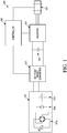
- FIG. 1 is a schematic illustration of an inverter-converter system 100 for a HVAC system, according to some embodiments.
- the inverter-converter system 100 includes a DC source 101, a DC to DC boost converter 102, a DC link capacitor 103, an inverter circuit 104, a variable speed electric machine 105, and a controller 106.
- the DC link capacitor 103 can be part of the DC to DC boost converter 102.
- the DC source 101 provides an input DC voltage to the DC to DC boost converter 102.
- the DC to DC boost converter 102 receives the input DC voltage from the DC source 101.
- the DC source 101 can be a rectified alternating current (AC) shore power source 101a, a vehicle DC power supply 101b, or a DC battery 101c.
- the rectified AC shore power source 101a can come from, for example, a 120 volts, 220 volts, or 240 volts input.
- the vehicle DC power supply 101b can be an alternator coupled to, for example, a prime mover of the vehicle.
- the DC source 101 is not limited to the examples discussed above and can be any suitable DC power source.
- the input DC voltage provided by the DC source 101 can be 12 volts. In other embodiments, the input DC voltage can be any suitable DC voltage, for example, 24 volts or 48 volts.
- the DC to DC boost converter 102 boosts up the input DC voltage from the DC source 101 to a variable output voltage to the DC link capacitor 103.
- the DC to DC boost converter 102 can boost the input DC voltage boost voltage to, for example, 170 volts.
- the DC to DC boost converter 102 can boost the input DC voltage boost voltage to, for example, 340 volts. It will be appreciated that in other embodiments, the DC to DC boost converter 102 can boost the input DC voltage to any suitable voltage (for example, 170 volts, 240 volts, 340 volts, etc.) as required for desired application.
- the DC to DC boost converter 102 can include a first DC to DC converter (not shown) that converts the input voltage to 12 volts, and a second DC to DC converter (not shown) that boosts up the 12 volts input voltage to a variable output voltage, with the variable output voltage being sent to the DC link capacitor 103.
- the DC link capacitor 103 stores the power obtained from the DC to DC boost converter 102 while the power is being converted back to AC power via the inverter circuit 104.
- the DC link capacitor can be in a range of at or about 0.1 millifarad to at or about 2 millifarad for a voltage from at or about 250 volts to at or about 500 volts.
- the inverter circuit 104 converts the boosted voltage outputted by the DC to DC boost converter 102 to an AC voltage to drive the variable speed electric machine 105.
- the inverter circuit 104 (sometimes called an inverter bridge) can include switches
- the switches can be controlled on and/or off to generate a variable power (for example, variable frequency, variable current, variable voltage, etc.) from an input DC voltage (i.e. the boosted voltage outputted by the DC to DC boost converter 102) to drive the variable speed electric machine 105.
- a variable power for example, variable frequency, variable current, variable voltage, etc.
- Matching the AC voltage and the voltage needed by the variable speed electric machine 105 can be an efficient way to utilize the energy from the DC source 101, and converting a full boosted voltage to a corresponding AC voltage can be an efficient conversion for the inverter circuit 104.
- the embodiments described herein can get a lower boosted voltage from the DC link capacitor 103 (i.e.
- the embodiments described herein can have a controller 106 to control the DC to DC boost converter 102 to generate a variable boosted voltage based on the voltage (or load) needed by the variable speed electric machine 105.
- the variable speed electric machine 105 is driven by the AC voltage from the inverter circuit 104.
- the variable speed electric machine 105 can be, for example, a compressor (not shown), a fan, etc.
- the compressor can be a variable speed compressor for a vehicle HVAC system.
- the compressor can be a two-speed compressor for a HVAC system that includes a high speed/power for providing rapid cooling or heating to a space and a low speed/power for maintaining a desired temperature in the space.
- the two-speed compressor can be a three-phase AC compressor that requires 280 volts at high speed/power and requires 140 volts at low speed/power.
- the two-speed compressor can be a three-phase AC compressor that requires 240 volts at high speed/power and requires 120 volts at low speed/power.
- a higher load on the variable speed electric machine 105 can require a higher speed and/or a higher voltage to drive the variable speed electric machine 105 and a lower load on the variable speed electric machine 105 can require a lower speed and/or a lower voltage to drive the variable speed electric machine 105.
- the controller 106 controls the DC to DC boost converter 102 based on the voltage (or load) needed by the variable speed electric machine 105.
- the controller 106 can receive data from a plurality of sensors (not shown).
- the plurality of sensors can monitor a plurality of parameters such as, for example, a mechanic torque requirement of the variable speed electric machine 105 (for example, a load on the variable speed electric machine 105), an optimum power requirement (for example, voltage, current, and/or frequency) of the variable speed electric machine 105, a calculated (or rated) speed of the variable speed electric machine 105, an output AC voltage of the inverter circuit 104, an output current of the inverter circuit 104, an output frequency of the inverter circuit 104, etc.
- the controller 106 can control the DC to DC boost converter 102 based on any or all of the sensed parameters. The detailed description of controlling the DC to DC boost converter 102 using the controller 106 can be found in the description of FIG. 2 .
- variable speed electric machine 105 can be integrated to a hermetic compressor that can be used in an APU in an HVAC system for a vehicle, for example, a semi-truck.
- the compressor can run at a multiple speeds based on the load on the compressor.
- the APU can be operated when a main prime mover of the vehicle is turned off such as, for example, when a driver parks the vehicle for an extended period of time to rest.
- the APU can provide, for example, power to operate a secondary HVAC unit to provide conditioned air to a cabin of the vehicle.
- the APU can also provide power to operate cabin accessories within the cabin such as a television, a microwave, a coffee maker, a refrigerator, etc.
- the compressor can run at a high speed (that requires a higher input voltage) to operate the secondary HVAC system at a high capacity provide rapid temperature control (e.g., cooling) to the cabin.
- the compressor can run at a low speed (that requires a lower input voltage) to operate the secondary HVAC system at a low capacity to maintain a temperature within the cabin.
- the low speed mode can be the predominant operation mode of the compressor. It will be appreciated that generally the APU can operate more efficiently (e.g., require less energy) when the compressor is running at low speed regardless of whether the APU is a mechanically driven APU (e.g., prime mover driven) or an electrically driven APU (e.g., battery driven).
- the prime mover can require less fuel (e.g., be more fuel efficient) when the compressor is operating at low speed versus operating at high speed.
- less energy from the battery may be required when the compressor is operating at low speed versus operating at high speed. It will be appreciated that generally operating at lower speed can result in more run time.
- the APU can have a limited run time based on the amount of fuel stored or based on battery capacity. Accordingly, the embodiments described herein can improve the efficiency and reduce the energy loss of the compressor and extend the battery longevity.
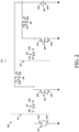
- FIG. 2 is a circuit diagram of a DC to DC boost converter 202 in a boost converter unit 200 for a HVAC system, according to some embodiments.
- the boost converter unit 200 includes a DC power supply 201, a DC to DC boost converter 202, and a DC link capacitor 203.
- the DC to DC boost converter 202 includes a first boost circuit 204 and a second boost circuit 205.
- the structure and function of the DC power supply 201 can be similar to the he DC source 101 in FIG. 1 .
- the structure and function of the DC link capacitor 203 can be similar to the DC link capacitor 103 in FIG. 1 .
- the structure and function of the DC to DC boost converter 202 can be similar to the DC to DC boost converter 102 in FIG. 1 .
- the first boost circuit 204 includes a first inductor 210 and a first set of switches (a first switch element 220 and a second switch element 230).
- the second boost circuit 205 includes a second inductor 240 and a second set of switches (a third switch element 250 and a fourth switch element 260).
- inductance value of the inductors can depend on specific application requirements and, for example, input and output voltages, output current and ripple, switching frequency, etc.
- the first inductor 210 and the second inductor 240 can be tapped winding magnetics.
- switch elements 220, 230, 250, and 260 can be one or more of a Metal-Oxide-Semiconductor Field-Effect Transistor (MOSFET), Insulated Gate Bipolar Transistor (IGBT), Bipolar Junction Transistor (BJT) or the like.
- MOSFET Metal-Oxide-Semiconductor Field-Effect Transistor
- IGBT Insulated Gate Bipolar Transistor
- BJT Bipolar Junction Transistor
- the DC power supply 201 includes a positive electrode 201a and a negative electrode 201b.
- the first inductor 210 includes a first end 210a and a second end 210b.
- the second inductor 240 includes a first end 240a and a second end 240b.
- the first switch element 220 includes a source terminal 220a and a drain terminal 220b.
- the second switch element 230 includes a source terminal 230a and a drain terminal 230b.
- the third switch element 250 includes a source terminal 250a and a drain terminal 250b.
- the fourth switch element 260 includes a source terminal 260a and a drain terminal 260b.
- the DC link capacitor 203 includes a first end 203a and a second end 203b.
- the drain terminal 230b of the second switch element 230 and the drain terminal 260b of the fourth switch element 260 connect to the first end 203a of the DC link capacitor 203.
- the source terminal 220a of the first switch element 220, the source terminal 250a of the third switch element 250, and the negative electrode 201b of the DC power supply 201 connect to the second end 203b of the DC link capacitor 203.
- the drain terminal 205b of the third switch element 250 and the source terminal 260a of the fourth switch element 260 connect to the second end 240b of the second inductor 240.
- the second end 210b of the first inductor 210, the drain terminal 220b of the first switch element 220, and the source terminal 230a of the second switch element 230 connect to the first end 240a of the second inductor 240.
- the positive electrode 201a of the DC power supply 201 connects to the first end 210a of the first inductor 210.
- the negative electrode 201b of the DC power supply 201 can be grounded.
- a controller (not shown, similar to the controller 106 in FIG. 1 ) can control the switch elements 220, 230, 250, and 260 based on a plurality of parameters sensed by a plurality of sensors (now shown) and sent to the controller.
- the controller can turn the second set of switches (switch element 250 and switch element 260) off.
- the first boost circuit 204 (including the first inductor 210, the first switch element 220, and the second switch element 230) can boost the input DC voltage to the first boosted voltage.
- the second inductor 240 is disconnected (i.e. not used) from the circuit.
- the controller can control or command the switch elements 220 and/or 230 to charge the first inductor 210 and to change the state to transfer energy from the first inductor 210 into the DC link capacitor 203.
- the controller can turn the first set of switches (switch element 220 and 230) off.
- the first inductor 210 and the second boost circuit 205 (including the second inductor 240, the third switch element 250, and the fourth switch element 260) can boost the input DC voltage to the second boosted voltage.
- the first inductor 210 and the second inductor 240 are connected (or used) in series.
- the controller can control or command the switch elements 250 and/or 260 to charge the first inductor 210 and the second inductor 240 and to change the state to transfer energy from the first inductor 210 and the second inductor 240 into the DC link capacitor 203.
- the design shown in FIG. 2 i.e. the combination of the first inductor 210 and the second inductor 240 for high voltage and the use of first inductor 210 for low voltage
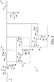
- FIG. 3 is a circuit diagram of another DC to DC boost converter 302 in a boost converter unit 300 for a HVAC system, according to some embodiments.
- the DC to DC boost converter unit 300 includes a DC power supply 301, a DC to DC boost converter 302, a DC link capacitor 303, and a load 309.
- the DC to DC boost converter 302 includes a first boost circuit 304, a second boost circuit 305, and a third boost circuit 306.
- the structure and function of the first boost circuit 304 and the second boost circuit 305 can be similar to the first boost circuit 204 and the second boost circuit 205 respectively in FIG. 2 .
- the structure and function of the DC power supply 301 and the DC link capacitor 303 can be similar to the DC power supply 201 and the DC link capacitor 203 respectively in FIG. 2 .
- the structure and function of the load 309 can be similar to the inverter circuit 104 combined with the variable speed electric machine 105 in FIG. 1 .
- the third boost circuit 306 includes a third inductor 370 and a third set of switches (a fifth switch element 380 and a sixth switch element 390).
- the third inductor 370 includes a first end 370a and a second end 370b.
- the fifth switch element 380 includes a source terminal 380a and a drain terminal 380b.
- the sixth switch element 390 includes a source terminal 390a and a drain terminal 390b.
- the first end 370a of the third inductor 370 connects to the second end 340b of the second inductor 340.
- the second end 370b of the third inductor 370 and the drain terminal 380b of the fifth switch element 380 connect to the source terminal 390a of the sixth switch element 390.
- the source terminal 380a of the fifth switch element 380 connects to the second end 303b of the DC link capacitor 303.
- the drain terminal 390b of the sixth switch element 390 connects to the first end 303a of the DC link
- a controller (not shown, similar to the controller 106 in FIG. 1 ) can control the switch elements 320, 330, 350, 360, 380, and 390 based on a plurality of parameters sensed by a plurality of sensors (now shown) sent to the controller.
- the controller can turn both the second set of switches (switch element 350 and switch element 360) and the third set of switches (switch element 380 and switch element 390) off.
- the first boost circuit 304 (including the first inductor 310, the first switch element 320, and the second switch element 330) can boost the input DC voltage to the first boosted voltage.
- the second inductor 340 and the third inductor 370 are disconnected (i.e. not used) from the circuit.
- the controller can switch the switch elements 320 and/or 330 to charge the first inductor 310 and to change the state to transfer energy from the first inductor 310 into the DC link capacitor 303.
- the controller can turn both the first set of switches (switch element 320 and 330) and the third set of switches (switch element 380 and switch element 390) off.
- the first inductor 310 and the second boost circuit 305 (including the second inductor 340, the third switch element 350, and the fourth switch element 360) can boost the input DC voltage to the second boosted voltage.
- the first inductor 310 and the second inductor 340 are connected (or used) in series.
- the third inductor 370 is disconnected (i.e. not used) from the circuit.
- the controller can switch the switch elements 350 and/or 360 to charge the first inductor 310 and the second inductor 340 and to change the state to transfer energy from the first inductor 310 and the second inductor 340 into the DC link capacitor 303.
- the controller can turn both the first set of switches (switch element 320 and 330) and the second set of switches (switch element 350 and switch element 360) off.
- the first inductor 310, the second inductor 340, and the third boost circuit 306 can boost the input DC voltage to the third boosted voltage.
- the first inductor 310, the second inductor 340, and the third inductor 370 are connected (or used) in series.
- the controller can switch the switch elements 380 and/or 390 to charge the first inductor 310, the second inductor 340, and the third inductor 370, and to change the state to transfer energy from the first inductor 310, the second inductor 340, and the third inductor 370 into the DC link capacitor 303.
- new boost circuit(s) can go further to get a whole range of boosted voltages for a whole range of speeds/loads of the variable speed electric machine.
- FIG. 4 illustrates a torque/power-speed relationship diagram of a variable speed electric machine, according to some embodiments.
- FIG. 4 shows a first data curve 401 that illustrates the relationship between the torque and the speed of the variable speed electric machine.
- FIG. 4 also shows a second data curve 402 that illustrates the relationship between the power (voltage, current, and/or frequency) and the speed of the variable speed electric machine.
- MTPA maximum torque per ampere
- the maximum torque remains constant (i.e. in a constant torque region) and the power needed to run the variable speed electric machine increases as the speed of the variable speed electric machine increases. It will be appreciated that current in the constant torque region can be a constant that is close to a maximum limit. Increasing the speed of the variable speed electric machine beyond the MTPA point 403 causes the maximum torque 401 to drop (i.e. in a field weakening region) while the power output by the variable speed electric machine remains constant. Different loads can have their own torque/power-speed relationship diagram and their own MTPA point.
- a controller (not shown) can be used to control a DC to DC boost converter to generate a variable boosted voltage based on the torque and/or power needed by the variable speed electric machine at the MTPA point 403 (or at the rated speed) for a particular load.
- simulation data shows that by using a inverter-converter system as described in FIG. 1 , there can be an about 125.1141 watts reduction in input power (input to the DC to DC boost converter), an about 10.42671 ampere reduction in input current (input to the DC to DC boost converter), and an about 17.87% efficiency gain in the system.
- efficiency gain can be calculated by comparing input power without the invention versus a simulated efficiency considering the DC to DC boost converter losses and new losses from the inverter and the variable speed electric machine.
- the simulation data is based on a two-speed electric machine that generates about 240 volts at full speed/power and about 120 volts at half speed/power, an about 12 volts input DC voltage to a DC to DC boost converter, a first boosted voltage about 170 volts, and a second boosted voltage about 340 volts.
- the detailed description of controlling the DC to DC boost converter by the controller based on the torque and/or power requirement needed by the variable speed electric machine is discussed above with respect to FIGs. 1-3 .
- any of aspects 1 - 5 can be combined with any of aspects 6 - 11, and that any of aspects 6-11 can be combined with aspect 12 - 14.
Landscapes
- Engineering & Computer Science (AREA)
- Power Engineering (AREA)
- Dc-Dc Converters (AREA)
- Inverter Devices (AREA)
Abstract
Description
- This disclosure relates generally to the power management of a direct current (DC) to direct current converter (DC to DC converter) for a heating, ventilation, and air conditioning (HVAC) system. More specifically, the disclosure relates to devices, systems and methods for efficiently sourcing a multiple DC link voltage to drive a variable speed electric machine in a HVAC system.
- A boost converter is a DC to DC converter that changes a source (i.e. input) voltage to an output voltage greater than the source voltage. The source voltage can be any suitable DC source, such as a rectifier, a DC generator, a battery, a solar panel, etc. A typical switch-mode boost converter includes an inductor, a switch, and a flywheel diode. The switch is can be a Metal-Oxide-Semiconductor Field-Effect Transistor (MOSFET), an Insulated Gate Bipolar Transistor (IGBT), or a Bipolar Junction Transistor (BJT), or the like. The flywheel diode can be replaced by a MOSFET. A typical boost converter can boost a fixed source voltage to a fixed output voltage.
- This disclosure relates generally to the power management of a DC to DC converter for powering a HVAC system. More specifically, the disclosure relates to devices, systems and methods for efficiently sourcing a multiple DC link voltage to drive a variable speed electric machine in a HVAC system.
- In one embodiment, an inverter-converter system for a HVAC system includes a DC to DC boost converter, a DC source providing an input DC voltage to the DC to DC boost converter, a controller, and a variable speed electric machine. The controller is configured to obtain a plurality of sensed parameters, for example, a load of the variable speed electric machine, to control the DC to DC boost converter to generate one of a first boosted voltage and a second boosted voltage based on the sensed plurality of parameters.
- In one embodiment, the DC to DC boost converter includes a first boost circuit that has a first inductor and a first set of switches. The DC to DC boost converter further includes a second boost circuit that has a second inductor and a second set of switches. In one embodiment, the first set of switches and the second set of switches can be N-type metal-oxide-semiconductor (NMOS) switch elements. In one embodiment, the first inductor and/or the second inductor can be a tapped winding electromagnetic coil with or without a magnetic core. In another embodiment, the first inductor and/or the second inductor can be a flyback transformer with or without magnetic core. The energy storage magnetics, for example, the inductors, can have multiple taps available. The taps can be chosen to optimize the amount of inductance required by the DC to DC boost converter to lower power losses in the DC to DC boost converter. A tap can be accompanied by a pair of switch elements. For each additional tap of the magnetics, an additional pair of switch elements would be required. If an upstream tap is not required, the pair of switch elements for that tap is turned off. To perform the boost function, the DC to DC boost converter would have to be synchronous rectification with the pair of switch elements for their corresponding tap/inductor.
- In one embodiment, the inverter-converter system for a HVAC system includes a DC to DC boost converter. The DC to DC boost converter includes a first boost circuit having a first inductor and a first set of switches, and a second boost circuit having a second inductor and a second set of switches. In one embodiment, the first inductor is connected to the second inductor in series when the first set of switches is off. When the second set of switches is off, the first boost circuit is configured to boost an input DC voltage to a first boosted voltage. When the first set of switches is off, the first inductor and the second boost circuit are configured to boost the input DC voltage to a second boosted voltage. The inverter-converter system also includes a DC source providing the input DC voltage to the DC to DC boost converter, a variable speed electric machine, and a controller that determines a load of the variable speed electric machine and controls the first and the second sets of switches based on the sensed load of the variable speed electric machine. In one embodiment, the DC to DC boost converter is configured to source one of the first boosted voltage and the second boosted voltage to the variable speed electric machine based on the sensed load of the variable speed electric machine.
- In one embodiment, the DC to DC boost converter for a HVAC system includes a first boost circuit having a first inductor and a first set of switches, and a second boost circuit having a second inductor and a second set of switches. In one embodiment, the first inductor is connected to the second inductor in series when the first set of switches is off. In one embodiment, when the second set of switches is off, the first boost circuit is configured to boost an input DC voltage to a first boosted voltage. When the first set of switches is off, the first inductor and the second boost circuit are configured to boost the input DC voltage to a second boosted voltage.
- In one embodiment, a DC to DC boost converter includes a first boost circuit having a first inductor and a first set of switches, and a second boost circuit having a second inductor and a second set of switches. The first inductor is connected to the second inductor in series when the first set of switches is off. In such embodiment, a method for operating the DC to DC boost converter includes receiving an input DC voltage from a DC source, and sensing a load of a variable speed electric machine. The method further includes when the load of the variable speed electric machine is sensed to require a first boosted voltage, switching the second set of switches off and the first boost circuit boosting the input DC voltage to the first boosted voltage. The method also includes when the load of the variable speed electric machine is sensed to require a second boosted voltage, switching the first set of switches off and the first inductor combined with the second boost circuit boosting the input DC voltage to the second boosted voltage.
- One of the advantages of the inverter-converter system is to optimize the electrical efficiency by using multiple tapped winding electromagnetic coils in the DC to DC boost converter to provide multiple boosted voltages to a DC link to drive a variable speed electric machine. A multiple output voltage DC to DC boost converter (that can generate variable boosted voltages) can have much higher efficiency than a single output voltage boost converter. Based on optimum operation points of the variable speed electric machine, the DC to DC boost converter can be designed to generate optimum boosted voltages with optimum tap of the windings of the electromagnetic coils.
- One of the advantages of the inverter-converter system is to optimize the efficiency for the variable speed electric machine at partial load, which makes up a significant portion of the overall runtime of the variable speed electric machine. The inverter-converter system can include a DC link capacitor. The boosted voltage by the DC to DC boost converter and the capacitance of the DC link capacitor can be designed for a highest load and highest voltage operation of the variable speed electric machine. At a lower load and lower voltage operation of the variable speed electric machine, such design would have extra design margin (for example, an extra capacitance design margin) that would lead to an increased life time of the components, for example, an increased life time of the DC link capacitor.
- Another advantage of the inverter-converter system is to achieve optimum performance or maximum efficiency of using the energy source, for example, a battery with limited capacity to ultimately drive the variable speed electric machine in an Auxiliary Power Unit (APU) application for a vehicle HVAC system. Another advantage of the inverter-converter system is to achieve optimum or maximum system efficiency to meet emissions laws.
- References are made to the accompanying drawings that form a part of this disclosure and which illustrate embodiments in which the systems and methods described in this specification can be practiced.
-
FIG. 1 is a schematic illustration of an inverter-converter system for a HVAC system, according to some embodiments. -
FIG. 2 is a circuit diagram of a DC to DC boost converter in a boost converter unit for a HVAC system, according to one embodiment. -
FIG. 3 is a circuit diagram of another DC to DC boost converter in a boost converter unit for a HVAC system, according to another embodiment. -
FIG. 4 illustrates a torque/power-speed relationship diagram of a variable speed electric machine, according to some embodiments. - Like reference numbers represent like parts throughout.
- This disclosure relates generally to the power management of a DC to DC converter for a HVAC system. More specifically, the disclosure relates to devices, systems and methods for efficiently sourcing a multiple DC link voltage to drive a variable speed electric machine in a HVAC system.
-
FIG. 1 is a schematic illustration of an inverter-converter system 100 for a HVAC system, according to some embodiments. The inverter-converter system 100 includes aDC source 101, a DC toDC boost converter 102, aDC link capacitor 103, aninverter circuit 104, a variable speedelectric machine 105, and acontroller 106. It will be appreciated that in other embodiments, theDC link capacitor 103 can be part of the DC toDC boost converter 102. - The
DC source 101 provides an input DC voltage to the DC toDC boost converter 102. The DC toDC boost converter 102 receives the input DC voltage from theDC source 101. InFIG. 1 , theDC source 101 can be a rectified alternating current (AC)shore power source 101a, a vehicle DC power supply 101b, or aDC battery 101c. The rectified ACshore power source 101a can come from, for example, a 120 volts, 220 volts, or 240 volts input. In one embodiment, the vehicle DC power supply 101b can be an alternator coupled to, for example, a prime mover of the vehicle. In will be appreciated that theDC source 101 is not limited to the examples discussed above and can be any suitable DC power source. In one embodiment, the input DC voltage provided by theDC source 101 can be 12 volts. In other embodiments, the input DC voltage can be any suitable DC voltage, for example, 24 volts or 48 volts. - The DC to
DC boost converter 102 boosts up the input DC voltage from theDC source 101 to a variable output voltage to theDC link capacitor 103. In one embodiment, the DC toDC boost converter 102 can boost the input DC voltage boost voltage to, for example, 170 volts. In another embodiment, the DC toDC boost converter 102 can boost the input DC voltage boost voltage to, for example, 340 volts. It will be appreciated that in other embodiments, the DC toDC boost converter 102 can boost the input DC voltage to any suitable voltage (for example, 170 volts, 240 volts, 340 volts, etc.) as required for desired application. In some embodiments, the DC toDC boost converter 102 can include a first DC to DC converter (not shown) that converts the input voltage to 12 volts, and a second DC to DC converter (not shown) that boosts up the 12 volts input voltage to a variable output voltage, with the variable output voltage being sent to theDC link capacitor 103. - The
DC link capacitor 103 stores the power obtained from the DC toDC boost converter 102 while the power is being converted back to AC power via theinverter circuit 104. In some embodiments, for a one kilo-watts operation, the DC link capacitor can be in a range of at or about 0.1 millifarad to at or about 2 millifarad for a voltage from at or about 250 volts to at or about 500 volts. - The
inverter circuit 104 converts the boosted voltage outputted by the DC toDC boost converter 102 to an AC voltage to drive the variable speedelectric machine 105. In some embodiments, the inverter circuit 104 (sometimes called an inverter bridge) can include switches - (not shown). The switches can be controlled on and/or off to generate a variable power (for example, variable frequency, variable current, variable voltage, etc.) from an input DC voltage (i.e. the boosted voltage outputted by the DC to DC boost converter 102) to drive the variable speed
electric machine 105. Matching the AC voltage and the voltage needed by the variable speedelectric machine 105 can be an efficient way to utilize the energy from theDC source 101, and converting a full boosted voltage to a corresponding AC voltage can be an efficient conversion for theinverter circuit 104. The embodiments described herein can get a lower boosted voltage from the DC link capacitor 103 (i.e. from the DC to DC boost converter 102) when the voltage needed by the variable speedelectric machine 105 is low, and get a higher boosted voltage from the DC link capacitor 103 (i.e. from the DC to DC boost converter 102) when the voltage needed by the variable speedelectric machine 105 is high. The embodiments described herein can have acontroller 106 to control the DC toDC boost converter 102 to generate a variable boosted voltage based on the voltage (or load) needed by the variable speedelectric machine 105. - The variable speed
electric machine 105 is driven by the AC voltage from theinverter circuit 104. In some embodiments, the variable speedelectric machine 105 can be, for example, a compressor (not shown), a fan, etc. In some embodiments, the compressor can be a variable speed compressor for a vehicle HVAC system. In other embodiments, the compressor can be a two-speed compressor for a HVAC system that includes a high speed/power for providing rapid cooling or heating to a space and a low speed/power for maintaining a desired temperature in the space. In one embodiment, the two-speed compressor can be a three-phase AC compressor that requires 280 volts at high speed/power and requires 140 volts at low speed/power. In another embodiment, the two-speed compressor can be a three-phase AC compressor that requires 240 volts at high speed/power and requires 120 volts at low speed/power. In general, a higher load on the variable speedelectric machine 105 can require a higher speed and/or a higher voltage to drive the variable speedelectric machine 105 and a lower load on the variable speedelectric machine 105 can require a lower speed and/or a lower voltage to drive the variable speedelectric machine 105. - The
controller 106 controls the DC toDC boost converter 102 based on the voltage (or load) needed by the variable speedelectric machine 105. In one embodiment, thecontroller 106 can receive data from a plurality of sensors (not shown). The plurality of sensors can monitor a plurality of parameters such as, for example, a mechanic torque requirement of the variable speed electric machine 105 (for example, a load on the variable speed electric machine 105), an optimum power requirement (for example, voltage, current, and/or frequency) of the variable speedelectric machine 105, a calculated (or rated) speed of the variable speedelectric machine 105, an output AC voltage of theinverter circuit 104, an output current of theinverter circuit 104, an output frequency of theinverter circuit 104, etc. Thecontroller 106 can control the DC toDC boost converter 102 based on any or all of the sensed parameters. The detailed description of controlling the DC toDC boost converter 102 using thecontroller 106 can be found in the description ofFIG. 2 . - In one embodiment, the variable speed
electric machine 105 can be integrated to a hermetic compressor that can be used in an APU in an HVAC system for a vehicle, for example, a semi-truck. The compressor can run at a multiple speeds based on the load on the compressor. The APU can be operated when a main prime mover of the vehicle is turned off such as, for example, when a driver parks the vehicle for an extended period of time to rest. The APU can provide, for example, power to operate a secondary HVAC unit to provide conditioned air to a cabin of the vehicle. The APU can also provide power to operate cabin accessories within the cabin such as a television, a microwave, a coffee maker, a refrigerator, etc. The compressor can run at a high speed (that requires a higher input voltage) to operate the secondary HVAC system at a high capacity provide rapid temperature control (e.g., cooling) to the cabin. The compressor can run at a low speed (that requires a lower input voltage) to operate the secondary HVAC system at a low capacity to maintain a temperature within the cabin. In some embodiments, the low speed mode can be the predominant operation mode of the compressor. It will be appreciated that generally the APU can operate more efficiently (e.g., require less energy) when the compressor is running at low speed regardless of whether the APU is a mechanically driven APU (e.g., prime mover driven) or an electrically driven APU (e.g., battery driven). For a mechanically driven APU, the prime mover can require less fuel (e.g., be more fuel efficient) when the compressor is operating at low speed versus operating at high speed. For an electrically driven APU, less energy from the battery may be required when the compressor is operating at low speed versus operating at high speed. It will be appreciated that generally operating at lower speed can result in more run time. Also, regardless of whether the APU is mechanically or electrically driven, the APU can have a limited run time based on the amount of fuel stored or based on battery capacity. Accordingly, the embodiments described herein can improve the efficiency and reduce the energy loss of the compressor and extend the battery longevity. -
FIG. 2 is a circuit diagram of a DC toDC boost converter 202 in aboost converter unit 200 for a HVAC system, according to some embodiments. Theboost converter unit 200 includes aDC power supply 201, a DC toDC boost converter 202, and aDC link capacitor 203. The DC toDC boost converter 202 includes afirst boost circuit 204 and asecond boost circuit 205. The structure and function of theDC power supply 201 can be similar to thehe DC source 101 inFIG. 1 . The structure and function of theDC link capacitor 203 can be similar to theDC link capacitor 103 inFIG. 1 . The structure and function of the DC toDC boost converter 202 can be similar to the DC toDC boost converter 102 inFIG. 1 . - Returning to
Fig. 2 , thefirst boost circuit 204 includes afirst inductor 210 and a first set of switches (afirst switch element 220 and a second switch element 230). Thesecond boost circuit 205 includes asecond inductor 240 and a second set of switches (athird switch element 250 and a fourth switch element 260). It will be appreciated that inductance value of the inductors can depend on specific application requirements and, for example, input and output voltages, output current and ripple, switching frequency, etc. In some embodiments, thefirst inductor 210 and thesecond inductor 240 can be tapped winding magnetics. In some embodiments, switchelements - In
FIG. 2 , theDC power supply 201 includes apositive electrode 201a and a negative electrode 201b. Thefirst inductor 210 includes afirst end 210a and a second end 210b. Thesecond inductor 240 includes afirst end 240a and asecond end 240b. Thefirst switch element 220 includes asource terminal 220a and a drain terminal 220b. Thesecond switch element 230 includes asource terminal 230a and a drain terminal 230b. Thethird switch element 250 includes asource terminal 250a and adrain terminal 250b. Thefourth switch element 260 includes a source terminal 260a and a drain terminal 260b. TheDC link capacitor 203 includes afirst end 203a and a second end 203b. - In
FIG. 2 , the drain terminal 230b of thesecond switch element 230 and the drain terminal 260b of thefourth switch element 260 connect to thefirst end 203a of theDC link capacitor 203. Thesource terminal 220a of thefirst switch element 220, thesource terminal 250a of thethird switch element 250, and the negative electrode 201b of theDC power supply 201 connect to the second end 203b of theDC link capacitor 203. The drain terminal 205b of thethird switch element 250 and the source terminal 260a of thefourth switch element 260 connect to thesecond end 240b of thesecond inductor 240. The second end 210b of thefirst inductor 210, the drain terminal 220b of thefirst switch element 220, and thesource terminal 230a of thesecond switch element 230 connect to thefirst end 240a of thesecond inductor 240. Thepositive electrode 201a of theDC power supply 201 connects to thefirst end 210a of thefirst inductor 210. In one embodiment, the negative electrode 201b of theDC power supply 201 can be grounded. - A controller (not shown, similar to the
controller 106 inFIG. 1 ) can control theswitch elements element 250 and switch element 260) off. The first boost circuit 204 (including thefirst inductor 210, thefirst switch element 220, and the second switch element 230) can boost the input DC voltage to the first boosted voltage. In such scenario, thesecond inductor 240 is disconnected (i.e. not used) from the circuit. During boosting, the controller can control or command theswitch elements 220 and/or 230 to charge thefirst inductor 210 and to change the state to transfer energy from thefirst inductor 210 into theDC link capacitor 203. - In operation, based on the sensed parameters, when a second boosted voltage, a high voltage, for example, 340 volts, is needed corresponding to a high speed requirement of the variable speed electric machine, the controller can turn the first set of switches (switch
element 220 and 230) off. Thefirst inductor 210 and the second boost circuit 205 (including thesecond inductor 240, thethird switch element 250, and the fourth switch element 260) can boost the input DC voltage to the second boosted voltage. In such scenario, thefirst inductor 210 and thesecond inductor 240 are connected (or used) in series. During boosting, the controller can control or command theswitch elements 250 and/or 260 to charge thefirst inductor 210 and thesecond inductor 240 and to change the state to transfer energy from thefirst inductor 210 and thesecond inductor 240 into theDC link capacitor 203. Compared with using one boost circuit for high voltage and another boost circuit for low voltage, the design shown inFIG. 2 (i.e. the combination of thefirst inductor 210 and thesecond inductor 240 for high voltage and the use offirst inductor 210 for low voltage) could save parts (for example, inductor) since the cost and/or weight of inductors can be high. -
FIG. 3 is a circuit diagram of another DC toDC boost converter 302 in aboost converter unit 300 for a HVAC system, according to some embodiments. The DC to DCboost converter unit 300 includes aDC power supply 301, a DC toDC boost converter 302, aDC link capacitor 303, and aload 309. The DC toDC boost converter 302 includes afirst boost circuit 304, asecond boost circuit 305, and athird boost circuit 306. The structure and function of thefirst boost circuit 304 and thesecond boost circuit 305 can be similar to thefirst boost circuit 204 and thesecond boost circuit 205 respectively inFIG. 2 . The structure and function of theDC power supply 301 and theDC link capacitor 303 can be similar to theDC power supply 201 and theDC link capacitor 203 respectively inFIG. 2 . The structure and function of theload 309 can be similar to theinverter circuit 104 combined with the variable speedelectric machine 105 inFIG. 1 . - In
FIG. 3 , thethird boost circuit 306 includes athird inductor 370 and a third set of switches (afifth switch element 380 and a sixth switch element 390). Thethird inductor 370 includes afirst end 370a and a second end 370b. Thefifth switch element 380 includes asource terminal 380a and a drain terminal 380b. Thesixth switch element 390 includes asource terminal 390a and adrain terminal 390b. Thefirst end 370a of thethird inductor 370 connects to thesecond end 340b of thesecond inductor 340. The second end 370b of thethird inductor 370 and the drain terminal 380b of thefifth switch element 380 connect to thesource terminal 390a of thesixth switch element 390. Thesource terminal 380a of thefifth switch element 380 connects to the second end 303b of theDC link capacitor 303. Thedrain terminal 390b of thesixth switch element 390 connects to thefirst end 303a of theDC link capacitor 303. - A controller (not shown, similar to the
controller 106 inFIG. 1 ) can control theswitch elements element 350 and switch element 360) and the third set of switches (switchelement 380 and switch element 390) off. The first boost circuit 304 (including thefirst inductor 310, thefirst switch element 320, and the second switch element 330) can boost the input DC voltage to the first boosted voltage. In such scenario, thesecond inductor 340 and thethird inductor 370 are disconnected (i.e. not used) from the circuit. During boosting, the controller can switch theswitch elements 320 and/or 330 to charge thefirst inductor 310 and to change the state to transfer energy from thefirst inductor 310 into theDC link capacitor 303. - In operation, based on the sensed parameters, when a second boosted voltage (i.e. a medium voltage) is needed corresponding to a medium speed requirement of the variable speed electric machine, the controller can turn both the first set of switches (switch
element 320 and 330) and the third set of switches (switchelement 380 and switch element 390) off. Thefirst inductor 310 and the second boost circuit 305 (including thesecond inductor 340, thethird switch element 350, and the fourth switch element 360) can boost the input DC voltage to the second boosted voltage. In such scenario, thefirst inductor 310 and thesecond inductor 340 are connected (or used) in series. Thethird inductor 370 is disconnected (i.e. not used) from the circuit. During boosting, the controller can switch theswitch elements 350 and/or 360 to charge thefirst inductor 310 and thesecond inductor 340 and to change the state to transfer energy from thefirst inductor 310 and thesecond inductor 340 into theDC link capacitor 303. - In operation, based on the sensed parameters, when a third boosted voltage (i.e. a high voltage) is needed corresponding to a high speed requirement of the variable speed electric machine, the controller can turn both the first set of switches (switch
element 320 and 330) and the second set of switches (switchelement 350 and switch element 360) off. Thefirst inductor 310, thesecond inductor 340, and the third boost circuit 306 (including thethird inductor 370, thefifth switch element 380, and the sixth switch element 390) can boost the input DC voltage to the third boosted voltage. In such scenario, thefirst inductor 310, thesecond inductor 340, and thethird inductor 370 are connected (or used) in series. During boosting, the controller can switch theswitch elements 380 and/or 390 to charge thefirst inductor 310, thesecond inductor 340, and thethird inductor 370, and to change the state to transfer energy from thefirst inductor 310, thesecond inductor 340, and thethird inductor 370 into theDC link capacitor 303. - It is to be appreciated that the addition of new boost circuit(s) can go further to get a whole range of boosted voltages for a whole range of speeds/loads of the variable speed electric machine.
-
FIG. 4 illustrates a torque/power-speed relationship diagram of a variable speed electric machine, according to some embodiments. In particular,FIG. 4 shows afirst data curve 401 that illustrates the relationship between the torque and the speed of the variable speed electric machine.FIG. 4 also shows asecond data curve 402 that illustrates the relationship between the power (voltage, current, and/or frequency) and the speed of the variable speed electric machine. InFIG. 4 , at the rated speed (i.e. the speed at which the variable speed electric machine is designed to operate with an appropriate torque load) of the variable speed electric machine, there is a maximum torque per ampere (MTPA)point 403. Increasing the speed of the variable speed electric machine beyond theMTPA point 403, there is a field weakening region. This can lead to flux weakening, which means power would be spent to counteract the physical property of the variable speed electric machine. Before theMTPA point 403 is reached, the maximum torque remains constant (i.e. in a constant torque region) and the power needed to run the variable speed electric machine increases as the speed of the variable speed electric machine increases. It will be appreciated that current in the constant torque region can be a constant that is close to a maximum limit. Increasing the speed of the variable speed electric machine beyond theMTPA point 403 causes themaximum torque 401 to drop (i.e. in a field weakening region) while the power output by the variable speed electric machine remains constant. Different loads can have their own torque/power-speed relationship diagram and their own MTPA point. - To achieve increased efficiency (optimum operation) of the variable speed electric machine and the overall system, a controller (not shown) can be used to control a DC to DC boost converter to generate a variable boosted voltage based on the torque and/or power needed by the variable speed electric machine at the MTPA point 403 (or at the rated speed) for a particular load. In one embodiment, simulation data shows that by using a inverter-converter system as described in
FIG. 1 , there can be an about 125.1141 watts reduction in input power (input to the DC to DC boost converter), an about 10.42671 ampere reduction in input current (input to the DC to DC boost converter), and an about 17.87% efficiency gain in the system. It will be appreciated that efficiency gain can be calculated by comparing input power without the invention versus a simulated efficiency considering the DC to DC boost converter losses and new losses from the inverter and the variable speed electric machine. The simulation data is based on a two-speed electric machine that generates about 240 volts at full speed/power and about 120 volts at half speed/power, an about 12 volts input DC voltage to a DC to DC boost converter, a first boosted voltage about 170 volts, and a second boosted voltage about 340 volts. The detailed description of controlling the DC to DC boost converter by the controller based on the torque and/or power requirement needed by the variable speed electric machine is discussed above with respect toFIGs. 1-3 . - It is to be appreciated that any of aspects 1 - 5 can be combined with any of aspects 6 - 11, and that any of aspects 6-11 can be combined with aspect 12 - 14.
-
Aspect 1. A DC to DC boost converter for a HVAC system, comprising:- a first boost circuit having a first inductor and a first set of switches; and
- a second boost circuit having a second inductor and a second set of switches,
- wherein the first inductor is connected to the second inductor in series when the first set of switches is off;
- wherein when the second set of switches is off, the first boost circuit is configured to boost an input DC voltage to a first boosted voltage; and
- wherein when the first set of switches is off, the first inductor and the second boost circuit are configured to boost the input DC voltage to a second boosted voltage.
- Aspect 2. The DC to DC boost converter according to
aspect 1, wherein the first set of switches and the second set of switches are MOSFET switches. - Aspect 3. The DC to DC boost converter according to
aspect 1 or aspect 2, wherein the first inductor and the second inductor are tapped winding electromagnetic coils. - Aspect 4. The DC to DC boost converter according to any one of aspects 1-3, further comprising:
- a third boost circuit having a third inductor and a third set of switches,
- wherein the first inductor, the second inductor, and the third inductor are connected in series when both the first set of switches and the second set of switches are off;
- wherein when both the second set of switches and the third set of switches are off, the first boost circuit is configured to boost the input DC voltage to the first boosted voltage;
- wherein when both the first set of switches and the third set of switches are off, the first inductor and the second boost circuit are configured to boost the input DC voltage to the second boosted voltage; and
- wherein when both the first set of switches and the second set of switches are off, the first inductor, the second inductor, and the third boost circuit are configured to boost the input DC voltage to a third boosted voltage.
- Aspect 5. The DC to DC boost converter according to any one of aspect 2-4, further comprising:
- a DC link capacitor having a first end and a second end,
- wherein the first inductor has a first end and a second end;
- wherein the second inductor has a first end and a second end;
- wherein the first set of switches includes a first switch element and a second switch element, the second set of switches includes a third switch element and a fourth switch element;
- wherein the drain terminal of the second switch element and the drain terminal of the fourth switch element connect to the first end of the DC link capacitor;
- wherein the source terminal of the first switch element and the source terminal of the third switch element connect to the second end of the DC link capacitor;
- wherein the drain terminal of the third switch element and the source terminal of the fourth switch element connect to the second end of the second inductor; and
- wherein the second end of the first inductor, the drain terminal of the first switch element, and the source terminal of the second switch element connect to the first end of the second inductor.
- Aspect 6. An inverter-converter system for a HVAC system, comprising:
- a DC to DC boost converter, the DC to DC boost converter includes:
- a first boost circuit having a first inductor and a first set of switches, and
- a second boost circuit having a second inductor and a second set of switches,
- wherein the first inductor is connected to the second inductor in series when the first set of switches is off,
- wherein when the second set of switches is off, the first boost circuit is configured to boost an input DC voltage to a first boosted voltage, and
- wherein when the first set of switches is off, the first inductor and the second boost circuit are configured to boost the input DC voltage to a second boosted voltage;
- a DC source providing the input DC voltage to the DC to DC boost converter;
- a variable speed electric machine; and
- a controller that determines a load of the variable speed electric machine and controls the first and the second sets of switches based on the sensed load of the variable speed electric machine,
- wherein the DC to DC boost converter is configured to source one of the first boosted voltage and the second boosted voltage to the variable speed electric machine based on the sensed load of the variable speed electric machine.
- a DC to DC boost converter, the DC to DC boost converter includes:
- Aspect 7. The inverter-converter system according to aspect 6, further comprising:
- an inverter circuit for converting one of the first boosted voltage and the second boosted voltage to an AC voltage,
- wherein the variable speed electric machine is driven by the AC voltage.
- Aspect 8. The inverter-converter system according to aspect 6 or aspect 7, wherein the input DC voltage is about 12 volts.
- Aspect 9. The inverter-converter system according to any one of aspects 6-8, wherein the DC source is one of a battery source, a DC source, and a rectified AC source.
- Aspect 10. The inverter-converter system according to any one of aspects 6-9, wherein the first boosted voltage is about 170 volts and the second boosted voltage is about 340 volts.
- Aspect 11. The inverter-converter system according to any one of aspects 6-10, wherein the variable speed electric machine is a multi-speed AC-driven compressor.
- Aspect 12. A method for operating a DC to DC boost converter, the DC to DC boost converter including: a first boost circuit having a first inductor and a first set of switches; and a second boost circuit having a second inductor and a second set of switches, wherein the first inductor is connected to the second inductor in series when the first set of switches is off, the method comprising:
- receiving an input DC voltage from a DC source;
- sensing a load of a variable speed electric machine;
- when the load of the variable speed electric machine is sensed to require a first boosted voltage, switching the second set of switches off and the first boost circuit boosting the input DC voltage to the first boosted voltage; and
- when the load of the variable speed electric machine is sensed to require a second boosted voltage, switching the first set of switches off and the first inductor combined with the second boost circuit boosting the input DC voltage to the second boosted voltage.
- Aspect 13. The method according to aspect 12, wherein the DC to DC boost converter further includes a third boost circuit having a third inductor and a third set of switches,
- wherein the first inductor and the second inductor are connected to the third inductor in series when the first set of switches and the second set of switches are off,
- the method further comprising:
- when the load of the variable speed electric machine is sensed to require the first boosted voltage, switching the second set of switches and the third set of switches off and the first boost circuit boosting the input DC voltage to the first boosted voltage;
- when the load of the variable speed electric machine is sensed to require the second boosted voltage, switching the first set of switches and the third set of switches off and the first inductor combined with the second boost circuit boosting the input DC voltage to the second boosted voltage; and
- when the load of the variable speed electric machine is sensed to require a third boosted voltage, switching the first set of switches and the second set of switches off, and the first inductor and the second inductor combined with the third boost circuit boosting the input DC voltage to the third boosted voltage.
- Aspect 14. The method according to aspect 12 or aspect 13, further comprising:
- determining a flux weakening point for the load of the variable speed electric machine; and
- determining the first and second boosted voltages based on the flux weakening point.
Claims (14)
- A DC to DC boost converter for a HVAC system, comprising:a first boost circuit having a first inductor and a first set of switches; anda second boost circuit having a second inductor and a second set of switches,wherein the first inductor is connected to the second inductor in series when the first set of switches is off;wherein when the second set of switches is off, the first boost circuit is configured to boost an input DC voltage to a first boosted voltage; andwherein when the first set of switches is off, the first inductor and the second boost circuit are configured to boost the input DC voltage to a second boosted voltage.
- The DC to DC boost converter according to claim 1, wherein the first set of switches and the second set of switches are MOSFET switches.
- The DC to DC boost converter according to claim 1, wherein the first inductor and the second inductor are tapped winding electromagnetic coils.
- The DC to DC boost converter according to claim 1, further comprising:a third boost circuit having a third inductor and a third set of switches,wherein the first inductor, the second inductor, and the third inductor are connected in series when both the first set of switches and the second set of switches are off;wherein when both the second set of switches and the third set of switches are off, the first boost circuit is configured to boost the input DC voltage to the first boosted voltage;wherein when both the first set of switches and the third set of switches are off, the first inductor and the second boost circuit are configured to boost the input DC voltage to the second boosted voltage; andwherein when both the first set of switches and the second set of switches are off, the first inductor, the second inductor, and the third boost circuit are configured to boost the input DC voltage to a third boosted voltage.
- The DC to DC boost converter according to claim 2, further comprising:a DC link capacitor having a first end and a second end,wherein the first inductor has a first end and a second end;wherein the second inductor has a first end and a second end;wherein the first set of switches includes a first switch element and a second switch element, the second set of switches includes a third switch element and a fourth switch element;wherein the drain terminal of the second switch element and the drain terminal of the fourth switch element connect to the first end of the DC link capacitor;wherein the source terminal of the first switch element and the source terminal of the third switch element connect to the second end of the DC link capacitor;wherein the drain terminal of the third switch element and the source terminal of the fourth switch element connect to the second end of the second inductor; andwherein the second end of the first inductor, the drain terminal of the first switch element, and the source terminal of the second switch element connect to the first end of the second inductor.
- An inverter-converter system for a HVAC system, comprising:a DC to DC boost converter, the DC to DC boost converter includes:a first boost circuit having a first inductor and a first set of switches, anda second boost circuit having a second inductor and a second set of switches,wherein the first inductor is connected to the second inductor in series when the first set of switches is off,wherein when the second set of switches is off, the first boost circuit is configured to boost an input DC voltage to a first boosted voltage, andwherein when the first set of switches is off, the first inductor and the second boost circuit are configured to boost the input DC voltage to a second boosted voltage;a DC source providing the input DC voltage to the DC to DC boost converter;a variable speed electric machine; anda controller that determines a load of the variable speed electric machine and controls the first and the second sets of switches based on the sensed load of the variable speed electric machine,wherein the DC to DC boost converter is configured to source one of the first boosted voltage and the second boosted voltage to the variable speed electric machine based on the sensed load of the variable speed electric machine.
- The inverter-converter system according to claim 6, further comprising:an inverter circuit for converting one of the first boosted voltage and the second boosted voltage to an AC voltage,wherein the variable speed electric machine is driven by the AC voltage.
- The inverter-converter system according to claim 6, wherein the input DC voltage is about 12 volts.
- The inverter-converter system according to claim 6, wherein the DC source is one of a battery source, a DC source, and a rectified AC source.
- The inverter-converter system according to claim 6, wherein the first boosted voltage is about 170 volts and the second boosted voltage is about 340 volts.
- The inverter-converter system according to claim 6, wherein the variable speed electric machine is a multi-speed AC-driven compressor.
- A method for operating a DC to DC boost converter, the DC to DC boost converter including a first boost circuit having a first inductor and a first set of switches; and a second boost circuit having a second inductor and a second set of switches, wherein the first inductor is connected to the second inductor in series when the first set of switches is off,
the method comprising:receiving an input DC voltage from a DC source;sensing a load of a variable speed electric machine;when the load of the variable speed electric machine is sensed to require a first boosted voltage, switching the second set of switches off and the first boost circuit boosting the input DC voltage to the first boosted voltage; andwhen the load of the variable speed electric machine is sensed to require a second boosted voltage, switching the first set of switches off and the first inductor combined with the second boost circuit boosting the input DC voltage to the second boosted voltage. - The method according to claim 12, wherein the DC to DC boost converter further includes a third boost circuit having a third inductor and a third set of switches,
wherein the first inductor and the second inductor are connected to the third inductor in series when the first set of switches and the second set of switches are off,
the method further comprising:when the load of the variable speed electric machine is sensed to require the first boosted voltage, switching the second set of switches and the third set of switches off and the first boost circuit boosting the input DC voltage to the first boosted voltage;when the load of the variable speed electric machine is sensed to require the second boosted voltage, switching the first set of switches and the third set of switches off and the first inductor combined with the second boost circuit boosting the input DC voltage to the second boosted voltage; andwhen the load of the variable speed electric machine is sensed to require a third boosted voltage, switching the first set of switches and the second set of switches off, and the first inductor and the second inductor combined with the third boost circuit boosting the input DC voltage to the third boosted voltage. - The method according to claim 12, further comprising:determining a flux weakening point for the load of the variable speed electric machine; anddetermining the first and second boosted voltages based on the flux weakening point.
Applications Claiming Priority (1)
| Application Number | Priority Date | Filing Date | Title |
|---|---|---|---|
| US15/400,316 US10148212B2 (en) | 2017-01-06 | 2017-01-06 | DC to DC converter sourcing variable DC link voltage |
Publications (2)
| Publication Number | Publication Date |
|---|---|
| EP3346595A1 true EP3346595A1 (en) | 2018-07-11 |
| EP3346595B1 EP3346595B1 (en) | 2021-06-30 |
Family
ID=60935759
Family Applications (1)
| Application Number | Title | Priority Date | Filing Date |
|---|---|---|---|
| EP18150512.4A Active EP3346595B1 (en) | 2017-01-06 | 2018-01-05 | Dc to dc boost converter for supplying a hvac system being sourced by a variable dc voltage |
Country Status (4)
| Country | Link |
|---|---|
| US (2) | US10148212B2 (en) |
| EP (1) | EP3346595B1 (en) |
| CN (1) | CN108282086B (en) |
| ES (1) | ES2889399T3 (en) |
Cited By (2)
| Publication number | Priority date | Publication date | Assignee | Title |
|---|---|---|---|---|
| EP3460975A1 (en) * | 2017-09-22 | 2019-03-27 | Thermo King Corporation | Dc to dc converter sourcing variable dc link voltage |
| EP3901542A1 (en) * | 2020-04-22 | 2021-10-27 | Carrier Corporation | Voltage conversion system for transport refrigeration system |
Families Citing this family (30)
| Publication number | Priority date | Publication date | Assignee | Title |
|---|---|---|---|---|
| EP3626489A1 (en) | 2018-09-19 | 2020-03-25 | Thermo King Corporation | Methods and systems for energy management of a transport climate control system |
| EP3626490A1 (en) | 2018-09-19 | 2020-03-25 | Thermo King Corporation | Methods and systems for power and load management of a transport climate control system |
| US11273684B2 (en) | 2018-09-29 | 2022-03-15 | Thermo King Corporation | Methods and systems for autonomous climate control optimization of a transport vehicle |
| US11034213B2 (en) | 2018-09-29 | 2021-06-15 | Thermo King Corporation | Methods and systems for monitoring and displaying energy use and energy cost of a transport vehicle climate control system or a fleet of transport vehicle climate control systems |
| US10926610B2 (en) | 2018-10-31 | 2021-02-23 | Thermo King Corporation | Methods and systems for controlling a mild hybrid system that powers a transport climate control system |
| US10875497B2 (en) | 2018-10-31 | 2020-12-29 | Thermo King Corporation | Drive off protection system and method for preventing drive off |
| US11059352B2 (en) | 2018-10-31 | 2021-07-13 | Thermo King Corporation | Methods and systems for augmenting a vehicle powered transport climate control system |
| US10870333B2 (en) | 2018-10-31 | 2020-12-22 | Thermo King Corporation | Reconfigurable utility power input with passive voltage booster |
| US11022451B2 (en) | 2018-11-01 | 2021-06-01 | Thermo King Corporation | Methods and systems for generation and utilization of supplemental stored energy for use in transport climate control |
| US11554638B2 (en) | 2018-12-28 | 2023-01-17 | Thermo King Llc | Methods and systems for preserving autonomous operation of a transport climate control system |
| US11993131B2 (en) | 2018-12-31 | 2024-05-28 | Thermo King Llc | Methods and systems for providing feedback for a transport climate control system |
| US11072321B2 (en) | 2018-12-31 | 2021-07-27 | Thermo King Corporation | Systems and methods for smart load shedding of a transport vehicle while in transit |
| WO2020142066A1 (en) | 2018-12-31 | 2020-07-09 | Thermo King Corporation | Methods and systems for providing predictive energy consumption feedback for powering a transport climate control system using external data |
| WO2020142061A1 (en) | 2018-12-31 | 2020-07-09 | Thermo King Corporation | Methods and systems for notifying and mitigating a suboptimal event occurring in a transport climate control system |
| US12097751B2 (en) | 2018-12-31 | 2024-09-24 | Thermo King Llc | Methods and systems for providing predictive energy consumption feedback for powering a transport climate control system |
| EP3756914B1 (en) | 2019-06-28 | 2023-09-27 | Thermo King LLC | Climate controlled vehicle, transport climate control equipment, method of retrofitting a vehicle and method of operation |
| US11135894B2 (en) | 2019-09-09 | 2021-10-05 | Thermo King Corporation | System and method for managing power and efficiently sourcing a variable voltage for a transport climate control system |
| US11376922B2 (en) | 2019-09-09 | 2022-07-05 | Thermo King Corporation | Transport climate control system with a self-configuring matrix power converter |
| US11214118B2 (en) | 2019-09-09 | 2022-01-04 | Thermo King Corporation | Demand-side power distribution management for a plurality of transport climate control systems |
| US11203262B2 (en) | 2019-09-09 | 2021-12-21 | Thermo King Corporation | Transport climate control system with an accessory power distribution unit for managing transport climate control loads |
| US11420495B2 (en) | 2019-09-09 | 2022-08-23 | Thermo King Corporation | Interface system for connecting a vehicle and a transport climate control system |
| US10985511B2 (en) | 2019-09-09 | 2021-04-20 | Thermo King Corporation | Optimized power cord for transferring power to a transport climate control system |
| US11458802B2 (en) | 2019-09-09 | 2022-10-04 | Thermo King Corporation | Optimized power management for a transport climate control energy source |
| EP3789221B1 (en) | 2019-09-09 | 2024-06-26 | Thermo King LLC | Prioritized power delivery for facilitating transport climate control |
| US11794551B2 (en) | 2019-09-09 | 2023-10-24 | Thermo King Llc | Optimized power distribution to transport climate control systems amongst one or more electric supply equipment stations |
| CN114946113A (en) * | 2019-11-27 | 2022-08-26 | 老虎工具国际公司 | DC-DC boost converter system and method |
| US11489431B2 (en) | 2019-12-30 | 2022-11-01 | Thermo King Corporation | Transport climate control system power architecture |
| GB2592246B (en) * | 2020-02-21 | 2024-11-13 | Dyson Technology Ltd | A system |
| US12328080B2 (en) | 2021-10-28 | 2025-06-10 | Carrier Corporation | Boost converter state control |
| WO2024215317A1 (en) * | 2023-04-12 | 2024-10-17 | Saia-Burgess Llc | Power supply system and method for an inductive load |
Citations (3)
| Publication number | Priority date | Publication date | Assignee | Title |
|---|---|---|---|---|
| WO1999056384A1 (en) * | 1998-04-27 | 1999-11-04 | Hua Wei Electronic Company Ltd., Shenzhen | A topology circuit of a soft switch |
| US20140104889A1 (en) * | 2012-10-12 | 2014-04-17 | Fuji Electric Co., Ltd. | Power supply device |
| EP2884641A1 (en) * | 2013-12-10 | 2015-06-17 | LG Electronics Inc. | Motor driving device and air conditioner including the same |
Family Cites Families (24)
| Publication number | Priority date | Publication date | Assignee | Title |
|---|---|---|---|---|
| US3967175A (en) * | 1975-02-27 | 1976-06-29 | General Electric Company | Automatic sequencing scheme for reversing directions of electric traction motors |
| DE19960991C1 (en) | 1999-12-17 | 2001-03-22 | Clariant Gmbh | Molded composition used in the production of ceramic and powder metallurgy molded parts by compressing contains sintered powder and metallocene-polyolefin wax |
| JP2004364492A (en) * | 2003-05-09 | 2004-12-24 | Sanyo Electric Co Ltd | Motor drive device and air conditioner |
| KR20050111204A (en) | 2004-05-21 | 2005-11-24 | 엘지전자 주식회사 | Method for power factor compensation of inverter control circuit |
| JP2008104337A (en) * | 2006-09-21 | 2008-05-01 | Sanyo Electric Co Ltd | Control unit of electromotor for refrigerant compressor |
| DE102007003415A1 (en) | 2007-01-23 | 2008-07-31 | Deutsches Zentrum für Luft- und Raumfahrt e.V. | Electrical voltage supply unit i.e. power supply unit, for producing output direct current voltage, has boost or buck converter with output at which intermediate link direct current voltage is produced |
| US7728562B2 (en) * | 2007-07-27 | 2010-06-01 | Gm Global Technology Operations, Inc. | Voltage link control of a DC-AC boost converter system |
| US8488350B2 (en) * | 2009-09-25 | 2013-07-16 | Astec International Limited | DC-AC inverters |
| US8860359B2 (en) | 2009-10-09 | 2014-10-14 | Illinois Institute Of Technology | Hybrid energy storage system |
| TWI371911B (en) | 2009-11-03 | 2012-09-01 | Ind Tech Res Inst | Resonance circuit structure of dc to ac converter for dc chain voltage control and action method |
| JP4893804B2 (en) * | 2009-11-05 | 2012-03-07 | トヨタ自動車株式会社 | Vehicle power supply |
| US8493039B2 (en) * | 2011-03-30 | 2013-07-23 | Shenzhen China Star Optoelectronics Co. Ltd. | Cascade-connected boost circuit |
| KR20120114813A (en) * | 2011-04-08 | 2012-10-17 | 삼성디스플레이 주식회사 | Dc-dc converter and driving device of light source for display device using the same |
| WO2012157569A1 (en) * | 2011-05-18 | 2012-11-22 | 国立大学法人東京大学 | Integrated circuit device |
| US8569963B2 (en) * | 2011-06-17 | 2013-10-29 | Intersil Americas Inc. | Cascade boost and inverting buck converter with independent control |
| JP5780914B2 (en) * | 2011-10-24 | 2015-09-16 | 株式会社豊田中央研究所 | Power converter control device and control method |
| US9118241B2 (en) * | 2012-06-13 | 2015-08-25 | Intel Deutschland Gmbh | Switched-mode power supply and a two-phase DC to DC converter having switches and a filter that deliver current from a node among converter stages |
| US9876394B1 (en) * | 2014-05-07 | 2018-01-23 | Energous Corporation | Boost-charger-boost system for enhanced power delivery |
| US8981686B2 (en) | 2013-01-24 | 2015-03-17 | Regal Beloit America, Inc. | Methods and systems for controlling an electric motor |
| DE102013104376B3 (en) * | 2013-04-30 | 2014-09-25 | Sma Railway Technology Gmbh | Boost converter with resonant circuit |
| KR101687870B1 (en) * | 2014-04-09 | 2016-12-21 | 숭실대학교산학협력단 | Power conversion circuit for ripple rejection |
| TWI524638B (en) * | 2014-05-23 | 2016-03-01 | 華碩電腦股份有限公司 | Boost converter and power supplying method |
| KR102350484B1 (en) * | 2014-12-01 | 2022-01-17 | 삼성전자주식회사 | Moter driving apparatus, airconditioner having the same and control method thereof |
| US10033276B2 (en) * | 2015-03-06 | 2018-07-24 | Texas Instruments Incorporated | Current sensing using capacitor voltage ripple in hybrid capacitor/inductor power converters |
-
2017
- 2017-01-06 US US15/400,316 patent/US10148212B2/en active Active
-
2018
- 2018-01-05 EP EP18150512.4A patent/EP3346595B1/en active Active
- 2018-01-05 ES ES18150512T patent/ES2889399T3/en active Active
- 2018-01-05 CN CN201810011665.0A patent/CN108282086B/en active Active
- 2018-11-07 US US16/182,959 patent/US11128247B2/en active Active
Patent Citations (3)
| Publication number | Priority date | Publication date | Assignee | Title |
|---|---|---|---|---|
| WO1999056384A1 (en) * | 1998-04-27 | 1999-11-04 | Hua Wei Electronic Company Ltd., Shenzhen | A topology circuit of a soft switch |
| US20140104889A1 (en) * | 2012-10-12 | 2014-04-17 | Fuji Electric Co., Ltd. | Power supply device |
| EP2884641A1 (en) * | 2013-12-10 | 2015-06-17 | LG Electronics Inc. | Motor driving device and air conditioner including the same |
Cited By (4)
| Publication number | Priority date | Publication date | Assignee | Title |
|---|---|---|---|---|
| EP3460975A1 (en) * | 2017-09-22 | 2019-03-27 | Thermo King Corporation | Dc to dc converter sourcing variable dc link voltage |
| US10840807B2 (en) | 2017-09-22 | 2020-11-17 | Thermo King Corporation | DC to DC converter sourcing variable DC link voltage |
| US11336181B2 (en) | 2017-09-22 | 2022-05-17 | Thermo King Corporation | DC to DC converter sourcing variable DC link voltage |
| EP3901542A1 (en) * | 2020-04-22 | 2021-10-27 | Carrier Corporation | Voltage conversion system for transport refrigeration system |
Also Published As
| Publication number | Publication date |
|---|---|
| ES2889399T3 (en) | 2022-01-12 |
| EP3346595B1 (en) | 2021-06-30 |
| US10148212B2 (en) | 2018-12-04 |
| US20180198399A1 (en) | 2018-07-12 |
| US20190074789A1 (en) | 2019-03-07 |
| US11128247B2 (en) | 2021-09-21 |
| CN108282086A (en) | 2018-07-13 |
| CN108282086B (en) | 2022-02-11 |
Similar Documents
| Publication | Publication Date | Title |
|---|---|---|
| EP3346595B1 (en) | Dc to dc boost converter for supplying a hvac system being sourced by a variable dc voltage | |
| US11336181B2 (en) | DC to DC converter sourcing variable DC link voltage | |
| US8541989B2 (en) | Power supply apparatus | |
| US6456514B1 (en) | Alternator jump charging system | |
| JP5553677B2 (en) | Output controller for hybrid generator | |
| US6111768A (en) | Multiple voltage alternator system | |
| US20230398889A1 (en) | In-vehicle charger | |
| JP2003164165A (en) | Circuit device | |
| KR102730545B1 (en) | Electric power conversion system and control method therefor | |
| WO2005006531A1 (en) | Three-phase power converter and power converter | |
| EP4039529B1 (en) | Electrically excited motor drive system integrated with obc, and electric vehicle | |
| JP2006101668A (en) | Power supply | |
| JP2018078756A (en) | Power converter and air conditioner using the same | |
| KR20190115364A (en) | Single and three phase combined charger | |
| KR20130129195A (en) | High efficiency led power supply | |
| JP3191097B2 (en) | Uninterruptible power supply and charge control method thereof | |
| JP2019041428A (en) | Power supply device and initial charging control method therefor | |
| JP2001268906A (en) | Dual voltage electric system having sub-resonance dc-dc converter for auto vehicle | |
| JP2008086107A (en) | Motor drive control device | |
| SUJATHA et al. | A Novel Bidirectional DC-DC converter drive |
Legal Events
| Date | Code | Title | Description |
|---|---|---|---|
| PUAI | Public reference made under article 153(3) epc to a published international application that has entered the european phase |
Free format text: ORIGINAL CODE: 0009012 |
|
| STAA | Information on the status of an ep patent application or granted ep patent |
Free format text: STATUS: THE APPLICATION HAS BEEN PUBLISHED |
|
| AK | Designated contracting states |
Kind code of ref document: A1 Designated state(s): AL AT BE BG CH CY CZ DE DK EE ES FI FR GB GR HR HU IE IS IT LI LT LU LV MC MK MT NL NO PL PT RO RS SE SI SK SM TR |
|
| AX | Request for extension of the european patent |
Extension state: BA ME |
|
| STAA | Information on the status of an ep patent application or granted ep patent |
Free format text: STATUS: REQUEST FOR EXAMINATION WAS MADE |
|
| 17P | Request for examination filed |
Effective date: 20190111 |
|
| RBV | Designated contracting states (corrected) |
Designated state(s): AL AT BE BG CH CY CZ DE DK EE ES FI FR GB GR HR HU IE IS IT LI LT LU LV MC MK MT NL NO PL PT RO RS SE SI SK SM TR |
|
| GRAP | Despatch of communication of intention to grant a patent |
Free format text: ORIGINAL CODE: EPIDOSNIGR1 |
|
| STAA | Information on the status of an ep patent application or granted ep patent |
Free format text: STATUS: GRANT OF PATENT IS INTENDED |
|
| INTG | Intention to grant announced |
Effective date: 20210114 |
|
| GRAS | Grant fee paid |
Free format text: ORIGINAL CODE: EPIDOSNIGR3 |
|
| GRAA | (expected) grant |
Free format text: ORIGINAL CODE: 0009210 |
|
| STAA | Information on the status of an ep patent application or granted ep patent |
Free format text: STATUS: THE PATENT HAS BEEN GRANTED |
|
| AK | Designated contracting states |
Kind code of ref document: B1 Designated state(s): AL AT BE BG CH CY CZ DE DK EE ES FI FR GB GR HR HU IE IS IT LI LT LU LV MC MK MT NL NO PL PT RO RS SE SI SK SM TR |
|
| REG | Reference to a national code |
Ref country code: CH Ref legal event code: EP |
|
| REG | Reference to a national code |
Ref country code: AT Ref legal event code: REF Ref document number: 1407285 Country of ref document: AT Kind code of ref document: T Effective date: 20210715 Ref country code: DE Ref legal event code: R096 Ref document number: 602018019158 Country of ref document: DE |
|
| REG | Reference to a national code |
Ref country code: IE Ref legal event code: FG4D |
|
| REG | Reference to a national code |
Ref country code: SE Ref legal event code: TRGR |
|
| REG | Reference to a national code |
Ref country code: LT Ref legal event code: MG9D |
|
| PG25 | Lapsed in a contracting state [announced via postgrant information from national office to epo] |
Ref country code: FI Free format text: LAPSE BECAUSE OF FAILURE TO SUBMIT A TRANSLATION OF THE DESCRIPTION OR TO PAY THE FEE WITHIN THE PRESCRIBED TIME-LIMIT Effective date: 20210630 Ref country code: BG Free format text: LAPSE BECAUSE OF FAILURE TO SUBMIT A TRANSLATION OF THE DESCRIPTION OR TO PAY THE FEE WITHIN THE PRESCRIBED TIME-LIMIT Effective date: 20210930 Ref country code: HR Free format text: LAPSE BECAUSE OF FAILURE TO SUBMIT A TRANSLATION OF THE DESCRIPTION OR TO PAY THE FEE WITHIN THE PRESCRIBED TIME-LIMIT Effective date: 20210630 |
|
| REG | Reference to a national code |
Ref country code: NL Ref legal event code: MP Effective date: 20210630 |
|
| REG | Reference to a national code |
Ref country code: AT Ref legal event code: MK05 Ref document number: 1407285 Country of ref document: AT Kind code of ref document: T Effective date: 20210630 |
|
| PG25 | Lapsed in a contracting state [announced via postgrant information from national office to epo] |
Ref country code: GR Free format text: LAPSE BECAUSE OF FAILURE TO SUBMIT A TRANSLATION OF THE DESCRIPTION OR TO PAY THE FEE WITHIN THE PRESCRIBED TIME-LIMIT Effective date: 20211001 Ref country code: NO Free format text: LAPSE BECAUSE OF FAILURE TO SUBMIT A TRANSLATION OF THE DESCRIPTION OR TO PAY THE FEE WITHIN THE PRESCRIBED TIME-LIMIT Effective date: 20210930 Ref country code: LV Free format text: LAPSE BECAUSE OF FAILURE TO SUBMIT A TRANSLATION OF THE DESCRIPTION OR TO PAY THE FEE WITHIN THE PRESCRIBED TIME-LIMIT Effective date: 20210630 Ref country code: RS Free format text: LAPSE BECAUSE OF FAILURE TO SUBMIT A TRANSLATION OF THE DESCRIPTION OR TO PAY THE FEE WITHIN THE PRESCRIBED TIME-LIMIT Effective date: 20210630 |
|
| REG | Reference to a national code |
Ref country code: ES Ref legal event code: FG2A Ref document number: 2889399 Country of ref document: ES Kind code of ref document: T3 Effective date: 20220112 |
|
| PG25 | Lapsed in a contracting state [announced via postgrant information from national office to epo] |
Ref country code: AT Free format text: LAPSE BECAUSE OF FAILURE TO SUBMIT A TRANSLATION OF THE DESCRIPTION OR TO PAY THE FEE WITHIN THE PRESCRIBED TIME-LIMIT Effective date: 20210630 Ref country code: CZ Free format text: LAPSE BECAUSE OF FAILURE TO SUBMIT A TRANSLATION OF THE DESCRIPTION OR TO PAY THE FEE WITHIN THE PRESCRIBED TIME-LIMIT Effective date: 20210630 Ref country code: PT Free format text: LAPSE BECAUSE OF FAILURE TO SUBMIT A TRANSLATION OF THE DESCRIPTION OR TO PAY THE FEE WITHIN THE PRESCRIBED TIME-LIMIT Effective date: 20211102 Ref country code: RO Free format text: LAPSE BECAUSE OF FAILURE TO SUBMIT A TRANSLATION OF THE DESCRIPTION OR TO PAY THE FEE WITHIN THE PRESCRIBED TIME-LIMIT Effective date: 20210630 Ref country code: NL Free format text: LAPSE BECAUSE OF FAILURE TO SUBMIT A TRANSLATION OF THE DESCRIPTION OR TO PAY THE FEE WITHIN THE PRESCRIBED TIME-LIMIT Effective date: 20210630 Ref country code: SK Free format text: LAPSE BECAUSE OF FAILURE TO SUBMIT A TRANSLATION OF THE DESCRIPTION OR TO PAY THE FEE WITHIN THE PRESCRIBED TIME-LIMIT Effective date: 20210630 Ref country code: SM Free format text: LAPSE BECAUSE OF FAILURE TO SUBMIT A TRANSLATION OF THE DESCRIPTION OR TO PAY THE FEE WITHIN THE PRESCRIBED TIME-LIMIT Effective date: 20210630 Ref country code: EE Free format text: LAPSE BECAUSE OF FAILURE TO SUBMIT A TRANSLATION OF THE DESCRIPTION OR TO PAY THE FEE WITHIN THE PRESCRIBED TIME-LIMIT Effective date: 20210630 |
|
| PG25 | Lapsed in a contracting state [announced via postgrant information from national office to epo] |
Ref country code: PL Free format text: LAPSE BECAUSE OF FAILURE TO SUBMIT A TRANSLATION OF THE DESCRIPTION OR TO PAY THE FEE WITHIN THE PRESCRIBED TIME-LIMIT Effective date: 20210630 |
|
| REG | Reference to a national code |
Ref country code: DE Ref legal event code: R097 Ref document number: 602018019158 Country of ref document: DE |
|
| PG25 | Lapsed in a contracting state [announced via postgrant information from national office to epo] |
Ref country code: DK Free format text: LAPSE BECAUSE OF FAILURE TO SUBMIT A TRANSLATION OF THE DESCRIPTION OR TO PAY THE FEE WITHIN THE PRESCRIBED TIME-LIMIT Effective date: 20210630 |
|
| PLBE | No opposition filed within time limit |
Free format text: ORIGINAL CODE: 0009261 |
|
| STAA | Information on the status of an ep patent application or granted ep patent |
Free format text: STATUS: NO OPPOSITION FILED WITHIN TIME LIMIT |
|
| PG25 | Lapsed in a contracting state [announced via postgrant information from national office to epo] |
Ref country code: AL Free format text: LAPSE BECAUSE OF FAILURE TO SUBMIT A TRANSLATION OF THE DESCRIPTION OR TO PAY THE FEE WITHIN THE PRESCRIBED TIME-LIMIT Effective date: 20210630 |
|
| 26N | No opposition filed |
Effective date: 20220331 |
|
| PG25 | Lapsed in a contracting state [announced via postgrant information from national office to epo] |
Ref country code: MC Free format text: LAPSE BECAUSE OF FAILURE TO SUBMIT A TRANSLATION OF THE DESCRIPTION OR TO PAY THE FEE WITHIN THE PRESCRIBED TIME-LIMIT Effective date: 20210630 |
|
| REG | Reference to a national code |
Ref country code: CH Ref legal event code: PL |
|
| REG | Reference to a national code |
Ref country code: BE Ref legal event code: MM Effective date: 20220131 |
|
| PG25 | Lapsed in a contracting state [announced via postgrant information from national office to epo] |
Ref country code: LU Free format text: LAPSE BECAUSE OF NON-PAYMENT OF DUE FEES Effective date: 20220105 |
|
| PG25 | Lapsed in a contracting state [announced via postgrant information from national office to epo] |
Ref country code: BE Free format text: LAPSE BECAUSE OF NON-PAYMENT OF DUE FEES Effective date: 20220131 |
|
| PG25 | Lapsed in a contracting state [announced via postgrant information from national office to epo] |
Ref country code: LI Free format text: LAPSE BECAUSE OF NON-PAYMENT OF DUE FEES Effective date: 20220131 Ref country code: CH Free format text: LAPSE BECAUSE OF NON-PAYMENT OF DUE FEES Effective date: 20220131 |
|
| PG25 | Lapsed in a contracting state [announced via postgrant information from national office to epo] |
Ref country code: IE Free format text: LAPSE BECAUSE OF NON-PAYMENT OF DUE FEES Effective date: 20220105 |
|
| PG25 | Lapsed in a contracting state [announced via postgrant information from national office to epo] |
Ref country code: LT Free format text: LAPSE BECAUSE OF FAILURE TO SUBMIT A TRANSLATION OF THE DESCRIPTION OR TO PAY THE FEE WITHIN THE PRESCRIBED TIME-LIMIT Effective date: 20210630 |
|
| P01 | Opt-out of the competence of the unified patent court (upc) registered |
Effective date: 20230511 |
|
| PG25 | Lapsed in a contracting state [announced via postgrant information from national office to epo] |
Ref country code: HU Free format text: LAPSE BECAUSE OF FAILURE TO SUBMIT A TRANSLATION OF THE DESCRIPTION OR TO PAY THE FEE WITHIN THE PRESCRIBED TIME-LIMIT; INVALID AB INITIO Effective date: 20180105 |
|
| PG25 | Lapsed in a contracting state [announced via postgrant information from national office to epo] |
Ref country code: MK Free format text: LAPSE BECAUSE OF FAILURE TO SUBMIT A TRANSLATION OF THE DESCRIPTION OR TO PAY THE FEE WITHIN THE PRESCRIBED TIME-LIMIT Effective date: 20210630 Ref country code: CY Free format text: LAPSE BECAUSE OF FAILURE TO SUBMIT A TRANSLATION OF THE DESCRIPTION OR TO PAY THE FEE WITHIN THE PRESCRIBED TIME-LIMIT Effective date: 20210630 |
|
| PG25 | Lapsed in a contracting state [announced via postgrant information from national office to epo] |
Ref country code: TR Free format text: LAPSE BECAUSE OF FAILURE TO SUBMIT A TRANSLATION OF THE DESCRIPTION OR TO PAY THE FEE WITHIN THE PRESCRIBED TIME-LIMIT Effective date: 20210630 |
|
| PG25 | Lapsed in a contracting state [announced via postgrant information from national office to epo] |
Ref country code: MT Free format text: LAPSE BECAUSE OF FAILURE TO SUBMIT A TRANSLATION OF THE DESCRIPTION OR TO PAY THE FEE WITHIN THE PRESCRIBED TIME-LIMIT Effective date: 20210630 |
|
| PGFP | Annual fee paid to national office [announced via postgrant information from national office to epo] |
Ref country code: GB Payment date: 20251219 Year of fee payment: 9 |
|
| PGFP | Annual fee paid to national office [announced via postgrant information from national office to epo] |
Ref country code: FR Payment date: 20251218 Year of fee payment: 9 |
|
| PGFP | Annual fee paid to national office [announced via postgrant information from national office to epo] |
Ref country code: SE Payment date: 20251217 Year of fee payment: 9 |
|
| PGFP | Annual fee paid to national office [announced via postgrant information from national office to epo] |
Ref country code: ES Payment date: 20260202 Year of fee payment: 9 |
|
| PGFP | Annual fee paid to national office [announced via postgrant information from national office to epo] |
Ref country code: DE Payment date: 20251217 Year of fee payment: 9 |
|
| PGFP | Annual fee paid to national office [announced via postgrant information from national office to epo] |
Ref country code: IT Payment date: 20260107 Year of fee payment: 9 |