EP3346148A1 - Joint pivotant - Google Patents
Joint pivotant Download PDFInfo
- Publication number
- EP3346148A1 EP3346148A1 EP17207207.6A EP17207207A EP3346148A1 EP 3346148 A1 EP3346148 A1 EP 3346148A1 EP 17207207 A EP17207207 A EP 17207207A EP 3346148 A1 EP3346148 A1 EP 3346148A1
- Authority
- EP
- European Patent Office
- Prior art keywords
- joint
- ball
- cup
- socket
- blank
- Prior art date
- Legal status (The legal status is an assumption and is not a legal conclusion. Google has not performed a legal analysis and makes no representation as to the accuracy of the status listed.)
- Granted
Links
- 239000002184 metal Substances 0.000 claims abstract description 11
- 229910052751 metal Inorganic materials 0.000 claims abstract description 11
- 229910000639 Spring steel Inorganic materials 0.000 claims abstract description 8
- 238000009434 installation Methods 0.000 claims description 36
- 238000004519 manufacturing process Methods 0.000 claims description 33
- 239000000463 material Substances 0.000 claims description 32
- 238000005520 cutting process Methods 0.000 claims description 21
- 238000005452 bending Methods 0.000 claims description 11
- 239000000725 suspension Substances 0.000 claims description 10
- 229910000831 Steel Inorganic materials 0.000 claims description 8
- 239000010959 steel Substances 0.000 claims description 8
- 238000009826 distribution Methods 0.000 claims description 7
- 230000007704 transition Effects 0.000 claims description 7
- 230000000295 complement effect Effects 0.000 claims description 6
- 238000005096 rolling process Methods 0.000 claims description 5
- 239000007769 metal material Substances 0.000 claims description 3
- 238000000034 method Methods 0.000 description 14
- 238000004080 punching Methods 0.000 description 11
- 230000008901 benefit Effects 0.000 description 10
- 238000013461 design Methods 0.000 description 6
- 238000003698 laser cutting Methods 0.000 description 6
- 230000000875 corresponding effect Effects 0.000 description 5
- 238000003672 processing method Methods 0.000 description 4
- 239000004918 carbon fiber reinforced polymer Substances 0.000 description 3
- 239000002131 composite material Substances 0.000 description 3
- 238000011161 development Methods 0.000 description 3
- 230000018109 developmental process Effects 0.000 description 3
- 230000002349 favourable effect Effects 0.000 description 3
- 239000004033 plastic Substances 0.000 description 3
- 229920003023 plastic Polymers 0.000 description 3
- 102100040287 GTP cyclohydrolase 1 feedback regulatory protein Human genes 0.000 description 2
- 101710185324 GTP cyclohydrolase 1 feedback regulatory protein Proteins 0.000 description 2
- 230000006978 adaptation Effects 0.000 description 2
- 230000033228 biological regulation Effects 0.000 description 2
- 230000008859 change Effects 0.000 description 2
- 230000006835 compression Effects 0.000 description 2
- 238000007906 compression Methods 0.000 description 2
- 239000011152 fibreglass Substances 0.000 description 2
- 229920000049 Carbon (fiber) Polymers 0.000 description 1
- 241001295925 Gegenes Species 0.000 description 1
- 230000002411 adverse Effects 0.000 description 1
- 230000004323 axial length Effects 0.000 description 1
- 238000010923 batch production Methods 0.000 description 1
- 230000009286 beneficial effect Effects 0.000 description 1
- 230000015572 biosynthetic process Effects 0.000 description 1
- 239000004917 carbon fiber Substances 0.000 description 1
- 238000010276 construction Methods 0.000 description 1
- 230000000694 effects Effects 0.000 description 1
- 230000007613 environmental effect Effects 0.000 description 1
- 239000003365 glass fiber Substances 0.000 description 1
- 238000002347 injection Methods 0.000 description 1
- 239000007924 injection Substances 0.000 description 1
- 238000003780 insertion Methods 0.000 description 1
- 230000037431 insertion Effects 0.000 description 1
- 238000003754 machining Methods 0.000 description 1
- 238000012423 maintenance Methods 0.000 description 1
- 230000014759 maintenance of location Effects 0.000 description 1
- 150000002739 metals Chemical class 0.000 description 1
- VNWKTOKETHGBQD-UHFFFAOYSA-N methane Chemical compound C VNWKTOKETHGBQD-UHFFFAOYSA-N 0.000 description 1
- 238000000465 moulding Methods 0.000 description 1
- 238000002360 preparation method Methods 0.000 description 1
- 102220232617 rs1085307576 Human genes 0.000 description 1
- 230000001932 seasonal effect Effects 0.000 description 1
- 238000007493 shaping process Methods 0.000 description 1
- 230000035939 shock Effects 0.000 description 1
- 239000007787 solid Substances 0.000 description 1
- 239000000243 solution Substances 0.000 description 1
- 239000002436 steel type Substances 0.000 description 1
Images


Classifications
-
- F—MECHANICAL ENGINEERING; LIGHTING; HEATING; WEAPONS; BLASTING
- F16—ENGINEERING ELEMENTS AND UNITS; GENERAL MEASURES FOR PRODUCING AND MAINTAINING EFFECTIVE FUNCTIONING OF MACHINES OR INSTALLATIONS; THERMAL INSULATION IN GENERAL
- F16C—SHAFTS; FLEXIBLE SHAFTS; ELEMENTS OR CRANKSHAFT MECHANISMS; ROTARY BODIES OTHER THAN GEARING ELEMENTS; BEARINGS
- F16C11/00—Pivots; Pivotal connections
- F16C11/04—Pivotal connections
- F16C11/06—Ball-joints; Other joints having more than one degree of angular freedom, i.e. universal joints
- F16C11/0619—Ball-joints; Other joints having more than one degree of angular freedom, i.e. universal joints the female part comprising a blind socket receiving the male part
-
- B—PERFORMING OPERATIONS; TRANSPORTING
- B60—VEHICLES IN GENERAL
- B60Q—ARRANGEMENT OF SIGNALLING OR LIGHTING DEVICES, THE MOUNTING OR SUPPORTING THEREOF OR CIRCUITS THEREFOR, FOR VEHICLES IN GENERAL
- B60Q1/00—Arrangement of optical signalling or lighting devices, the mounting or supporting thereof or circuits therefor
- B60Q1/02—Arrangement of optical signalling or lighting devices, the mounting or supporting thereof or circuits therefor the devices being primarily intended to illuminate the way ahead or to illuminate other areas of way or environments
- B60Q1/04—Arrangement of optical signalling or lighting devices, the mounting or supporting thereof or circuits therefor the devices being primarily intended to illuminate the way ahead or to illuminate other areas of way or environments the devices being headlights
- B60Q1/06—Arrangement of optical signalling or lighting devices, the mounting or supporting thereof or circuits therefor the devices being primarily intended to illuminate the way ahead or to illuminate other areas of way or environments the devices being headlights adjustable, e.g. remotely-controlled from inside vehicle
-
- F—MECHANICAL ENGINEERING; LIGHTING; HEATING; WEAPONS; BLASTING
- F16—ENGINEERING ELEMENTS AND UNITS; GENERAL MEASURES FOR PRODUCING AND MAINTAINING EFFECTIVE FUNCTIONING OF MACHINES OR INSTALLATIONS; THERMAL INSULATION IN GENERAL
- F16C—SHAFTS; FLEXIBLE SHAFTS; ELEMENTS OR CRANKSHAFT MECHANISMS; ROTARY BODIES OTHER THAN GEARING ELEMENTS; BEARINGS
- F16C11/00—Pivots; Pivotal connections
- F16C11/04—Pivotal connections
- F16C11/06—Ball-joints; Other joints having more than one degree of angular freedom, i.e. universal joints
- F16C11/0619—Ball-joints; Other joints having more than one degree of angular freedom, i.e. universal joints the female part comprising a blind socket receiving the male part
- F16C11/0623—Construction or details of the socket member
-
- F—MECHANICAL ENGINEERING; LIGHTING; HEATING; WEAPONS; BLASTING
- F16—ENGINEERING ELEMENTS AND UNITS; GENERAL MEASURES FOR PRODUCING AND MAINTAINING EFFECTIVE FUNCTIONING OF MACHINES OR INSTALLATIONS; THERMAL INSULATION IN GENERAL
- F16C—SHAFTS; FLEXIBLE SHAFTS; ELEMENTS OR CRANKSHAFT MECHANISMS; ROTARY BODIES OTHER THAN GEARING ELEMENTS; BEARINGS
- F16C11/00—Pivots; Pivotal connections
- F16C11/04—Pivotal connections
- F16C11/06—Ball-joints; Other joints having more than one degree of angular freedom, i.e. universal joints
- F16C11/0685—Manufacture of ball-joints and parts thereof, e.g. assembly of ball-joints
-
- F—MECHANICAL ENGINEERING; LIGHTING; HEATING; WEAPONS; BLASTING
- F16—ENGINEERING ELEMENTS AND UNITS; GENERAL MEASURES FOR PRODUCING AND MAINTAINING EFFECTIVE FUNCTIONING OF MACHINES OR INSTALLATIONS; THERMAL INSULATION IN GENERAL
- F16C—SHAFTS; FLEXIBLE SHAFTS; ELEMENTS OR CRANKSHAFT MECHANISMS; ROTARY BODIES OTHER THAN GEARING ELEMENTS; BEARINGS
- F16C11/00—Pivots; Pivotal connections
- F16C11/04—Pivotal connections
- F16C11/10—Arrangements for locking
- F16C11/103—Arrangements for locking frictionally clamped
- F16C11/106—Arrangements for locking frictionally clamped for ball joints
-
- F—MECHANICAL ENGINEERING; LIGHTING; HEATING; WEAPONS; BLASTING
- F21—LIGHTING
- F21V—FUNCTIONAL FEATURES OR DETAILS OF LIGHTING DEVICES OR SYSTEMS THEREOF; STRUCTURAL COMBINATIONS OF LIGHTING DEVICES WITH OTHER ARTICLES, NOT OTHERWISE PROVIDED FOR
- F21V21/00—Supporting, suspending, or attaching arrangements for lighting devices; Hand grips
-
- B—PERFORMING OPERATIONS; TRANSPORTING
- B60—VEHICLES IN GENERAL
- B60Q—ARRANGEMENT OF SIGNALLING OR LIGHTING DEVICES, THE MOUNTING OR SUPPORTING THEREOF OR CIRCUITS THEREFOR, FOR VEHICLES IN GENERAL
- B60Q1/00—Arrangement of optical signalling or lighting devices, the mounting or supporting thereof or circuits therefor
- B60Q1/02—Arrangement of optical signalling or lighting devices, the mounting or supporting thereof or circuits therefor the devices being primarily intended to illuminate the way ahead or to illuminate other areas of way or environments
- B60Q1/04—Arrangement of optical signalling or lighting devices, the mounting or supporting thereof or circuits therefor the devices being primarily intended to illuminate the way ahead or to illuminate other areas of way or environments the devices being headlights
- B60Q1/06—Arrangement of optical signalling or lighting devices, the mounting or supporting thereof or circuits therefor the devices being primarily intended to illuminate the way ahead or to illuminate other areas of way or environments the devices being headlights adjustable, e.g. remotely-controlled from inside vehicle
- B60Q1/076—Arrangement of optical signalling or lighting devices, the mounting or supporting thereof or circuits therefor the devices being primarily intended to illuminate the way ahead or to illuminate other areas of way or environments the devices being headlights adjustable, e.g. remotely-controlled from inside vehicle by electrical means including means to transmit the movements, e.g. shafts or joints
-
- B—PERFORMING OPERATIONS; TRANSPORTING
- B60—VEHICLES IN GENERAL
- B60Q—ARRANGEMENT OF SIGNALLING OR LIGHTING DEVICES, THE MOUNTING OR SUPPORTING THEREOF OR CIRCUITS THEREFOR, FOR VEHICLES IN GENERAL
- B60Q2200/00—Special features or arrangements of vehicle headlamps
- B60Q2200/30—Special arrangements for adjusting headlamps, e.g. means for transmitting the movements for adjusting the lamps
- B60Q2200/32—Ball-joints
-
- F—MECHANICAL ENGINEERING; LIGHTING; HEATING; WEAPONS; BLASTING
- F16—ENGINEERING ELEMENTS AND UNITS; GENERAL MEASURES FOR PRODUCING AND MAINTAINING EFFECTIVE FUNCTIONING OF MACHINES OR INSTALLATIONS; THERMAL INSULATION IN GENERAL
- F16C—SHAFTS; FLEXIBLE SHAFTS; ELEMENTS OR CRANKSHAFT MECHANISMS; ROTARY BODIES OTHER THAN GEARING ELEMENTS; BEARINGS
- F16C2220/00—Shaping
- F16C2220/40—Shaping by deformation without removing material
- F16C2220/42—Shaping by deformation without removing material by working of thin-walled material such as sheet or tube
-
- F—MECHANICAL ENGINEERING; LIGHTING; HEATING; WEAPONS; BLASTING
- F16—ENGINEERING ELEMENTS AND UNITS; GENERAL MEASURES FOR PRODUCING AND MAINTAINING EFFECTIVE FUNCTIONING OF MACHINES OR INSTALLATIONS; THERMAL INSULATION IN GENERAL
- F16C—SHAFTS; FLEXIBLE SHAFTS; ELEMENTS OR CRANKSHAFT MECHANISMS; ROTARY BODIES OTHER THAN GEARING ELEMENTS; BEARINGS
- F16C2220/00—Shaping
- F16C2220/40—Shaping by deformation without removing material
- F16C2220/44—Shaping by deformation without removing material by rolling
-
- F—MECHANICAL ENGINEERING; LIGHTING; HEATING; WEAPONS; BLASTING
- F16—ENGINEERING ELEMENTS AND UNITS; GENERAL MEASURES FOR PRODUCING AND MAINTAINING EFFECTIVE FUNCTIONING OF MACHINES OR INSTALLATIONS; THERMAL INSULATION IN GENERAL
- F16C—SHAFTS; FLEXIBLE SHAFTS; ELEMENTS OR CRANKSHAFT MECHANISMS; ROTARY BODIES OTHER THAN GEARING ELEMENTS; BEARINGS
- F16C2220/00—Shaping
- F16C2220/80—Shaping by separating parts, e.g. by severing, cracking
- F16C2220/84—Shaping by separating parts, e.g. by severing, cracking by perforating; by punching; by stamping-out
-
- F—MECHANICAL ENGINEERING; LIGHTING; HEATING; WEAPONS; BLASTING
- F16—ENGINEERING ELEMENTS AND UNITS; GENERAL MEASURES FOR PRODUCING AND MAINTAINING EFFECTIVE FUNCTIONING OF MACHINES OR INSTALLATIONS; THERMAL INSULATION IN GENERAL
- F16C—SHAFTS; FLEXIBLE SHAFTS; ELEMENTS OR CRANKSHAFT MECHANISMS; ROTARY BODIES OTHER THAN GEARING ELEMENTS; BEARINGS
- F16C2226/00—Joining parts; Fastening; Assembling or mounting parts
- F16C2226/50—Positive connections
- F16C2226/70—Positive connections with complementary interlocking parts
- F16C2226/74—Positive connections with complementary interlocking parts with snap-fit, e.g. by clips
-
- F—MECHANICAL ENGINEERING; LIGHTING; HEATING; WEAPONS; BLASTING
- F16—ENGINEERING ELEMENTS AND UNITS; GENERAL MEASURES FOR PRODUCING AND MAINTAINING EFFECTIVE FUNCTIONING OF MACHINES OR INSTALLATIONS; THERMAL INSULATION IN GENERAL
- F16C—SHAFTS; FLEXIBLE SHAFTS; ELEMENTS OR CRANKSHAFT MECHANISMS; ROTARY BODIES OTHER THAN GEARING ELEMENTS; BEARINGS
- F16C2226/00—Joining parts; Fastening; Assembling or mounting parts
- F16C2226/50—Positive connections
- F16C2226/70—Positive connections with complementary interlocking parts
- F16C2226/76—Positive connections with complementary interlocking parts with tongue and groove or key and slot
- F16C2226/78—Positive connections with complementary interlocking parts with tongue and groove or key and slot of jigsaw-puzzle type
-
- F—MECHANICAL ENGINEERING; LIGHTING; HEATING; WEAPONS; BLASTING
- F16—ENGINEERING ELEMENTS AND UNITS; GENERAL MEASURES FOR PRODUCING AND MAINTAINING EFFECTIVE FUNCTIONING OF MACHINES OR INSTALLATIONS; THERMAL INSULATION IN GENERAL
- F16C—SHAFTS; FLEXIBLE SHAFTS; ELEMENTS OR CRANKSHAFT MECHANISMS; ROTARY BODIES OTHER THAN GEARING ELEMENTS; BEARINGS
- F16C2326/00—Articles relating to transporting
- F16C2326/01—Parts of vehicles in general
Definitions
- the invention relates to a ball joint, in particular for fastening a headlight in a vehicle.
- the invention relates to a method for producing a joint socket for the ball joint.
- the headlight When installing a vehicle headlight in a motor vehicle, the headlight is mounted, for example, on a support frame, a body part or other component of the vehicle.
- the parts mentioned and the headlight itself have partly high tolerances in their dimensions, but also in the position and execution precision of the mounting units provided for mounting, such as holes, threads, alignment pins, screws, rivets, etc.
- Ball joints according to the prior art have the disadvantage that they have low locking moments, since they are often made of plastic material.
- the holding force of the ball joint for some applications may be insufficient, which may occur especially in the described connections between a vehicle headlight and a vehicle-mounted mounting part, since in motor vehicles, among other things, strong vibrations and high seasonal temperature fluctuations may affect the locking force of a ball joint connection.
- special requirements may also exist with regard to, for example, strength, shock, high-temperature resistance, lower coefficients of friction, which can not be met by conventional ball joints.
- currently available ball joints may be cumbersome to manufacture, such as when their individual components fall down during assembly.
- the invention provides a ball joint which is very easy to construct and manufacture, which results in cost advantages.
- the ball joint is very light.
- metal as a material for a Gelenkpan, that is for the blank for the production of joint socket, this is very well suited for use in harsh environmental conditions such as in a motor vehicle (very high and very low operating temperatures, high humidity, pollution) and has a very long life.
- the Gelenkpan is suitable to compensate for component tolerances of the joint ball, the joint socket and the pivot pin.
- various processing methods such as punching or laser cutting is suitable, which allow the production in each case of different precision.
- the different processing methods also allow adaptation to very different production volumes in order to benefit from the respective cost advantages.
- the ball and socket joint according to the invention has a fault-tolerant design, whereby the flexibility to be able to change the production process for the same joint socket between a prototype production and a mass production is a decisive advantage.
- the construction according to the invention assists in easy assembly of the ball joint in that the individual components snap into each other, hold themselves and consequently falling down individual parts can be avoided.
- the ball joint according to the invention is characterized in that the ball joint can be easily disassembled into its individual parts, which is the durability of the items and the ease of disassembly of the ball joint beneficial.
- the inner joint surface can not rest completely form-fitting manner on the joint ball, whereby, for example, the joint socket is particularly easy to produce.
- a joint socket can be provided, which has a very tight fit between the joint ball and the joint socket, to a particularly high locking torque to achieve.
- the joint cup has a hollow cylindrical basic shape. It is clear that the basic shape may differ in parts from the shape of a hollow cylinder, for example, there to form additional functions, such as additional mounting or attachment points, but also more retaining wings. Further, it is conceivable that, for example, due to a desired weight or material savings on parts of the surface of the hollow cylinder is dispensed with and corresponding openings are provided.
- the installation direction of the pivot pin and the installation direction of the joint socket is located in the same axis or oriented in the same direction.
- This concept of assembly results in a particularly simple assembly, for example in a vehicle headlight. It is advantageous that the composite ball joint pressure and / or tensile loads acting in and / or opposite to the mounting direction, record without affecting the stability of the connection, which is formed by the built-ball joint significantly within certain limits. Said load profile can be particularly in use in automotive headlamps to a high degree and caused by vibrations that occur when driving a vehicle or engines located therein.
- the pivot pin is still accessible on its end face, since there may be a mounting recess, for example in the form of a screwdriver or socket wrench receptacle for adjusting or locking the ball joint.
- Spring steel is a steel that has a higher strength compared to other steels. There are many applications of spring steel, such as the springs in motor vehicle chassis, but also the small spring compressing clothespins.
- the invention sets in a further development spring steel in a joint socket of a Ball joint, which is used for mounting a vehicle headlight in a motor vehicle, a.
- each component can be deformed up to a voltage determined by the material (elastic limit), in order then to return elastically to the initial state without permanent deformation.
- the material property that makes this possible is the elasticity. Beyond that deformations lead to plastic deformation.
- Table 1 Spring steels designation Material number. use Examples standardize old (DIN) designation X10CrNi18-8 1.4310 Spring plate, clamping sleeves, disc springs, etc. EN 10151 38Si7 1.5023 Spring washers, disc springs, etc. EN 10089 61SiCr7 1.7108 Leaf springs for vehicles, coil springs, etc.
- the spring steel 38Si7 1150 has an elastic limit of at least. N / mm 2 (at a tensile strength of 1300-1600 N / mm 2) compared with 235 N / mm 2 in the steel S235JR (tensile strength 360 N / mm 2).
- the decisive difference here is the yield ratio, that is the ratio of yield strength to tensile strength of the material, which is usually in the range of more than 85% for spring steels.
- Table 1 shows frequently used spring steels, which can form the base material for the blank of the joint socket of the ball joint according to the invention.
- materials such as other metals, plastics or composite materials for Gelenkspfanne can be used, which have corresponding properties for the production according to the invention.
- the ball joint according to the invention can be advantageously used by its design, especially for low-volume productions, but is also suitable for high production volumes.
- the ball joint according to the invention has the advantage that the joint socket is made in one piece and the manufacturing, logistics and maintenance costs can be reduced. Accordingly, such Gelenkspfannen can be formed by punching or cutting the basic shape of the joint socket, in the form of a blank, and anschumbleendes curling to a spatial shape, from which it is apparent how simple and inexpensive the production of a joint socket according to the invention can be carried out.
- pivot pins are commercially available as standard and have for example at the pivot pin on a thread.
- Such pivot pins can be designed such that the geometric center of the joint ball is located on the extension of the imaginary longitudinal axis of the joint shaft. It is therefore advantageous if the ball joint according to the invention supports the use of such standard goods.
- the said standard goods can be designed so that the joint ball is flattened on the side facing away from the joint shaft and preferably has a mounting recess.
- the mounting recess for example, a mounting recess in the form of an Allen or Torx opening for receiving a corresponding screwdriver, by means of which a thread located on the hinge shaft can be screwed, for example, in a support frame, a body part or other component of a vehicle.
- the ball joint further comprises a support frame for receiving the Gelenkpan.
- the ball joint can be used to fasten, for example, components in whose component housing a correspondingly provided support frame is integrated on a support structure, whereby large position and component tilt can be absorbed.
- the pivot pin should be spatially adjustable to the circumstances during assembly, for example in a vehicle headlight.
- this comprises at least two webs, preferably at least three webs, which are arranged along the circumference of the opening of the support frame and extend in the axial direction and are interconnected by at least one web connector.
- the inner surfaces of the at least two webs and / or the at least one web connector with respect to the outer surface of the joint socket formed at least partially complementary and adapted to support the joint socket. This ensures that the stability of the connection between the joint socket and the support frame is improved.
- At least two rear retaining wings are arranged along the circumference of the hollow cylindrical joint socket, which are oriented against the installation direction of the joint socket and are inclined radially away from the imaginary longitudinal axis of the joint socket and the at least two rear retaining wings are set, slipping the Gelenkpan to prevent in the mounting frame in the direction of installation of the joint socket.
- At least two front retaining wings are arranged, which are oriented against the direction of installation of the joint socket and radially from the imaginary longitudinal axis of the joint socket are inclined, are preferably oriented normal to the imaginary longitudinal axis of the joint socket, and the at least two front retaining wings are arranged to prevent slipping of the joint socket in the support frame against the direction of installation of the joint socket.
- the thus obtained self-holding force of the joint socket in the support frame is achieved in that the front and rear retaining wings are oriented towards each other and between the support frame is clamped by a spring force, which is generated in particular by the front retaining wings, against the support frame and the adjacent thereto rear retaining wing acts.
- Gelenkspfannen invention can be made by sawing, punching or cutting the basic shape of Gelenkspfanne, the blank, and anschconceendes curling to a spatially shaped shape, it is particularly advantageous if the hinge wing and / or the retaining wings axially strip-shaped, preferably as narrow strips extend. As a result, the basic shape of the joint socket can be rolled up particularly easily. Narrow strips have a narrow width compared to their length, for example a ratio of width to length of 1: 3 or 1: 5 or even more.
- the diameter of the joint ball is preferably greater than the radial diameter of the joint shaft, and a transition between the joint shaft and the joint ball is preferably formed by a concave surface extending along the circumference of the joint socket, and is formed on the surface of the pivot pin between the joint shaft and the joint ball extending along the circumference of the joint socket joint edge, wherein the joint edge preferably by a sectional curve of the substantially convex surface of the joint ball and the concave surface of the transition from the joint shaft to the joint ball is formed, and the rear joint wings in an unobstructed state, in which an imaginary longitudinal axis of the pivot pin coincides with an imaginary longitudinal axis of the joint socket, at least extend to the joint edge.
- the joint pin between the joint ball and the joint shank on a joint edge which limits the spatially rotatable region of the connection between the joint ball and Gelenkpan, to reach the joint wings of the joint socket in the unadjusted state. Due to the axial length of the joint wings, the effective joint surface of the ball joint, which is determined by the interacting surfaces of the joint ball and the socket joint, can be optimally utilized. A particularly high locking torque of a ball joint can be achieved.
- the effective hinge surface of the ball joint can be used to particular advantage if the joint edge is formed by a sectional curve of the substantially convex surface of the joint ball and the concave surface of the transition from the joint shaft to the joint ball.
- the joint socket is produced in one piece from a flat and preferably from a metallic material, particularly preferably from sheet steel, and preferably a material thickness between 0.1 mm and 1 mm, particularly preferably between 0.2 mm and 0.5 mm having.
- a material thickness between 0.1 mm and 1 mm, particularly preferably between 0.2 mm and 0.5 mm having.
- the Gelenkpan is made by rolling a pre-cut flat material. It is expedient if the joint socket comprises at least two mutually complementarily shaped alignment elements, which along the circumference the Gelenkpan are arranged and are arranged to interlock. This ensures that the joint socket has a stable shape, which is set up for a precise recording of the joint ball, and in particular improves the torsional rigidity of the joint socket.
- the shape of the alignment elements may be, for example, round, angular or tongue-shaped. If it is expedient for the desired stability of the joint socket, several alignment elements can also be used.
- the hollow cylindrical Gelenkpan is open at the front in the direction of installation end face.
- a mounting recess in the form of an Allen or Torx opening located in the joint ball is accessible and the mounting pin can be screwed in a vehicle-mounted bracket in the assembled state of the ball joint, for example by means of a thread which is located on the pivot pin.
- the ball joint can be arranged on or within a vehicle headlight and be adapted to fix the vehicle headlight in an installed position or to fix headlight components adjustable in the headlight.
- the ball joint according to the invention is particularly suitable for connecting parts in a vehicle headlight and partly to overcome and compensate for high installation tolerances, which happens in such a way that the ball joint is fixed only after attachment of the parts to a vehicle headlight.
- a vehicle headlight in particular for generating a high beam and / or a low beam light distribution, be provided with at least one ball joint according to the invention for installation of the vehicle headlight in a motor vehicle, wherein the ball joint connects a carrier unit located on the vehicle side with the vehicle headlight ,
- the ball joint according to the invention is also particularly suitable for fixing a vehicle headlight on a vehicle-mounted bracket in order to compensate for the sometimes high installation tolerances or to connect an adjustable in a support frame headlight module with the headlight housing adjustable.
- a vehicle headlight in particular for generating a high beam and / or a low beam light distribution, be provided with at least one ball joint according to the invention, wherein the ball joint forms a preferably solid leg, which together with two other adjustable legs a three-point suspension for fixing a lighting device of the vehicle headlight on a vehicle headlight component or a body part of the motor vehicle forms.
- the ball joint forms a preferably solid leg, which together with two other adjustable legs a three-point suspension for fixing a lighting device of the vehicle headlight on a vehicle headlight component or a body part of the motor vehicle forms.
- joint socket first cut from a flat material, for example by sawing, punching, (laser) cutting and then can be rolled to form the spatial shape of the joint cup.
- hinge wings or retaining wings can be done by their contours are cut from the blank and then bent out of the cutting plane in which the blank is located, so that the wings are pressed beyond the plane.
- the joint wings are bent in the opposite direction to that of the retaining wings, which may require two separate process steps.
- all those wings, which should ultimately be oriented in the same direction can be bent in the same process step.
- the bending can take place transversely to the cutting plane in two opposite directions but also in a single process step.
- the ball and socket joint according to the invention has a fault-tolerant design, whereby the flexibility to be able to change the production process for the same joint socket between a prototype production and a mass production is a decisive advantage.
- the same punching mold or the same control program for a laser cutting of the blank for a joint socket in order to machine different thicknesses of the blank, in particular of metal, wherein the punching die or the control program can be adapted, for example, to a maximum permissible material thickness during machining.
- the stroke across the cutting plane during subsequent bending different spring forces can be achieved for the joint socket, which are adapted according to different requirements in different applications of the ball joints.
- the desired spring forces can be set very precisely, which moreover can be very constant over a very long operating time.
- the use of alignment elements, each located at two ends of the blank allows for precise alignment of the two ends of the rolled blank.
- the joint socket also more stable in terms of shear forces.
- the hinge socket can be better fitted into a support structure, such as webs or web connectors, which may be complementary to one another, stiffness to tension or compression, torsional rigidity, and also precise alignment of the socket within the support frame to improve. This aspect is quite important for the application of a vehicle headlight, the operating influences such as vibrations or temperature fluctuations, the strength of the connection, which is formed by the ball joint, can adversely affect.
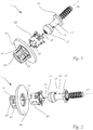
- FIGS. 1 to 12 show an inventive ball joint for a vehicle headlight or its components
- the Figures 13 and 14 illustrate a manufacturing method for producing a Gelenkpan for a ball joint
- the FIGS. 15 to 17 show a light module of a vehicle headlight having a ball joint according to the invention for a three-point suspension.
- a ball joint 1 which comprises a pivot pin 10, a joint cup 20 and a support frame 40. It can be seen the installation direction 15, in which the pivot pin 10 can be inserted into the joint socket 20, and the installation direction 31, in which the joint socket 20 can be inserted into the support frame 40.
- the ball joint 1 comprises a pivot pin 10, which comprises a joint ball 11, which merges on one side into an end face of a substantially cylindrically shaped joint shaft 12.
- the ball joint 1 thus comprises a joint socket 20 for receiving the joint ball 11, wherein the joint socket 20 has a hollow cylindrical basic shape and consists of a resilient metal, preferably made of spring steel.
- the joint cup 20 is detailed in FIG FIG. 3 and FIG. 4 shown.
- two rear joint wings 21 are formed along the circumference of the hollow cylindrical joint cup 20, which are oriented against the installation direction 15 of the pivot pin 10 and are inclined radially to the imaginary longitudinal axis 23 of the joint cup 20.
- three front joint wings 22 are further formed along the circumference of the hollow cylindrical joint cup 20, which are oriented in the installation direction 15 of the pivot pin 10 and are inclined radially to the imaginary longitudinal axis 23 of the joint cup 20
- the two rear joint wings 21 and the three front joint wings 22 at least partially form an inner joint surface of the ball joint 1, which rests against the joint ball 11 in the assembled state of the ball joint 1.
- the inner joint surface is not completely positive fit to the joint ball 11, whereby the joint cup 20 is particularly easy to produce.
- a Gelenkpan 20 may be provided which has a much closer fit between the joint ball 11 and the joint cup 20.
- Fig. 5 shows, inter alia, how the elements of the joint cup 20 engage in the support frame 40 and on the joint ball 11. It is with the aid of the detailed representation of the joint cup 20 in the FIGS. 8, 9 and 10 recognizable as the support frame 40 of the ball joint 1 for receiving the Joint socket 20 at least partially surrounds the two rear hinge wing 21 of the joint cup 20.
- Fig. 10 shows an inserted into the joint cup 20 pivot pin 10 in dashed form indicated in a sectional plane CC after Fig. 8 , It can be seen a joint edge 13 of a joint pin (see also Fig. 1 and Fig. 6 ).
- the joint edge 13 limits the joint surface of the joint ball 11 and that the joint cup 20 extends beyond the joint edge 13 and consequently a very high retention force of the fixed ball joint 1 can be achieved, even if an imaginary longitudinal axis 14 of the joint pin 10 not an imaginary longitudinal axis 23 of the joint cup 20 corresponds, that is, when the pivot pin 10 and the joint cup 20 have an angle to each other, for example, to compensate for a mounting tolerance between the support frame 40 and a vehicle headlamp, which is mounted by means of the ball joint 1.
- a joint edge 13 running along the circumference of the joint socket 20 may be formed on the surface of the joint pin 10 between the joint shaft 12 and the joint ball 11, wherein the joint edge 13 is preferably formed by a sectional curve of the substantially concave surface of the joint ball 11 and the convex Surface of the transition from the hinge shaft 12 to the joint ball 11 is formed.
- the retaining force of the ball joint 1 can be particularly large if the rear joint wings 21 extend in an unobstructed state, in which an imaginary longitudinal axis 14 of the joint pin 10 coincides with an imaginary longitudinal axis 23 of the joint socket 20, at least up to the joint edge 13.
- the two rear hinge wings 21 are pressed against the ball joint 11 by spring force.
- each rear retaining wings 24 are arranged along the circumference of the hollow cylindrical joint cup 20, which are oriented against the installation direction 31 of the joint cup 20 and radially inclined away from the imaginary longitudinal axis 23 of the joint cup 20 and the four rear Retaining wings 24 are set up, a slippage of the joint socket 20 in the support frame 40 in Installation direction 31 of the joint cup 20 to prevent. As a result, it can be prevented that the joint socket 20 can not be pressed too deeply into the support frame 40.
- four front retaining wings 25 are arranged for fastening the joint cup 20 with the support frame 40 along the circumference of the hollow cylindrical joint cup 20, which are oriented against the installation direction 31 of the joint cup 20 and normal to the imaginary longitudinal axis 23 of the joint cup 20 are oriented, and the four front Retaining wings 25 are arranged to prevent slipping of the joint socket 20 in the support frame 40 against the installation direction 31 of the joint socket 20. This can prevent that the joint socket 20 can not be pulled out of the support frame 40 again.
- Fig. 11 shows a plan view of the support frame 40, in which a joint cup 20 is inserted. Furthermore, a sectional plane DD can be seen whose view in the Fig. 12 you can see. Clearly the front retaining wings 25 and rear retaining wings 24 can be seen, which clamp the joint socket 20 in the support frame 40. As a result, a firm grip is provided, which provides a stop with respect to the support frame 40 in both the tension and compression directions. It can further be seen that the support frame 40 of the ball joint 1 for receiving the joint cup 20 at least partially surrounds the two rear joint wings 21 of the joint cup 20, whereby the so-called "springing" of the joint wings can be prevented.
- the support frame 40 in this embodiment three webs 41 which are arranged along the circumference of the opening of the support frame 40 and extend in the axial direction and are interconnected by a web connector 42 comprises.
- the inner surfaces of the three webs 41 and / or the web connector 42 with respect to the outer surface of the joint cup 20 are formed at least partially complementary shaped and adapted to support the joint cup 20.
- This arrangement serves to stabilize the connection between the joint socket 20 and the support frame 40.
- the three webs 41 are oriented substantially parallel to the installation direction of the joint socket 31. It is not essential whether the webs 41 are actually oriented parallel to the installation direction of the joint cup 31.
- any design of the webs 41 is possible, which serves to support the hollow cylindrical joint cup 20.
- the Webs 41 are in this example at their ends via a circular web connector 42 connected to each other to further improve the stability or the support of the joint cup 20.
- the webs 41 and the web connector 42 form a structure which is adapted to receive the hollow cylindrical basic shape of the joint socket 20 and to improve their hold in the installed position. As a result, shear forces acting on the joint socket, which can be induced by the joint pin or also by the support frame, can be reduced.
- a transition between the joint shaft 12 and the joint ball 11 may be formed by a concave surface extending along the circumference of the joint socket 20.
- the joint socket 20 is produced in one piece from a planar and metallic material, preferably from sheet steel type 1.4310, and preferably a material thickness between 0.1 mm and 1 mm, particularly preferably between 0.3 mm and 0 7 mm, for example 0.5 mm.
- the joint socket 20 which further comprises two mutually complementarily shaped alignment elements 27, 28 which are arranged along the circumference of the joint socket 20 and are adapted to engage in one another.
- the ball joint 1 is especially suitable and intended to be arranged on or within a vehicle headlight and is adapted to fix the vehicle headlight in an installed position.
- the ball joint 1 is particularly preferably suitable and intended to be installed in a vehicle-mounted carrier unit, wherein the ball joint 1 connects the carrier unit with the vehicle headlight, the vehicle headlight, in particular for generating a high beam and / or a low beam light distribution, is provided or to connect a fixed in a support frame headlight module with the headlight housing adjustable.
- Fig. 13 an already cut out blank 29 is shown, from which a joint socket according to the invention can be formed.
- the three front joint wings 22, the two rear joint wings 21, the four rear retaining wings 24, the four front retaining wings 25 and the two alignment elements 27, 28 can be seen.
- the cutting process can be done by punching, sawing or cutting, preferably laser cutting, but in principle also any other shaping process.
- the two aligning elements 27, 28, which are shaped in a complementary manner, can be seen, which ensure that the joint socket is mechanically stable and precisely adjusted in the finished state.
- the two rear hinge wings 21 and the three front hinge wings 22 of the joint cup 20 are thereby bent in the opposite direction normal to the plane 30 as the four rear retaining wings 24 and the four front retaining wings 25 of the joint cup 20, starting from the plane 30.
- Fig. 14c the third process step is shown, that is, the molding of the blank 29, so that the joint socket 20 is formed by rolling the blank 29 about the imaginary longitudinal axis 23 of the joint cup 20.
- Fig. 14d the last process step for the production of the joint socket 20 is shown, that is, the connecting or annular closing of the molded blank 29 from the Fig. 14c in that the two alignment elements 27, 28 which are complementary to one another engage in one another and thus have a precise alignment with one another, which is conducive to the mechanical stability of the joint socket 20.
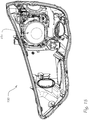
- Fig. 15 shows a vehicle headlight 100 with a light module 101.
- Fig. 16 illustrates that the light module 101 in the vehicle headlight 100 can be mounted by a three-point suspension.
- the three-point suspension comprises a fixed leg 110, which is formed from the ball joint 1 according to the invention with the pivot pin 10, the joint cup 20 and a support frame, which in this example is part of the light module 101, and two adjustable legs 111, 112 , which are designed as adjusting screws and thus allow easy adjustment, and preferably form an equilateral triangle with each other, in principle, all triangular arrangements of the three legs are suitable.
- the ball joint 1 on the fixed Bei 110 serves as a fixed point of the three-point suspension, which produces a spherically adjustable connection between the housing and modules.
- the light module 101 can be hinged to the vehicle headlight 100, a vehicle headlight component or a body part of a vehicle and offers the possibility of mutual fine adjustment.
- the pivot pin 10 has a thread on the hinge shaft 12 which can engage in an opening with a complementarily shaped internal thread and a rotation in the internal thread can perform a longitudinal movement in the direction of the imaginary longitudinal axis 14 of the pivot pin, whereby an additional adjustment movement of the Three-point suspension can be achieved.
- the two adjustable legs 111, 112 already provide sufficient adjustability.
- For exercising the rotation in the internal thread of the pivot pin 10 may have at its joint ball 11, for example, a slot or a recess in the form of a hexagonal volume for receiving a corresponding screwdriver, which is accessible through the light module 101.
- the support frame is shaped such that the support wings 24, 25 of the joint sleeve 20 can engage in the support frame to be mechanically fixed.
- Fig. 17 shows the light module 101 according to the Fig. 16 in the assembled state of the ball joint, which forms a fixed leg 110 and together with the two adjustable legs 111,112 forms the three-point suspension.
- the light module is provided in particular for generating a high beam and / or a low beam light distribution and may require a fine adjustment of the radiated light distribution according to operating regulations or statutory installation regulations. It may also be necessary for this fine adjustment to be repeated during operation of the vehicle.
Landscapes
- Engineering & Computer Science (AREA)
- General Engineering & Computer Science (AREA)
- Mechanical Engineering (AREA)
- Pivots And Pivotal Connections (AREA)
- Lighting Device Outwards From Vehicle And Optical Signal (AREA)
Applications Claiming Priority (1)
| Application Number | Priority Date | Filing Date | Title |
|---|---|---|---|
| ATA50011/2017A AT519541B1 (de) | 2017-01-10 | 2017-01-10 | Kugelgelenk |
Publications (2)
| Publication Number | Publication Date |
|---|---|
| EP3346148A1 true EP3346148A1 (fr) | 2018-07-11 |
| EP3346148B1 EP3346148B1 (fr) | 2020-03-11 |
Family
ID=60673541
Family Applications (1)
| Application Number | Title | Priority Date | Filing Date |
|---|---|---|---|
| EP17207207.6A Active EP3346148B1 (fr) | 2017-01-10 | 2017-12-14 | Joint pivotant |
Country Status (3)
| Country | Link |
|---|---|
| EP (1) | EP3346148B1 (fr) |
| CN (1) | CN108286565A (fr) |
| AT (1) | AT519541B1 (fr) |
Cited By (2)
| Publication number | Priority date | Publication date | Assignee | Title |
|---|---|---|---|---|
| WO2021136630A1 (fr) * | 2020-01-02 | 2021-07-08 | HELLA GmbH & Co. KGaA | Système d'assemblage présentant un élément de réception et un joint à rotule |
| WO2024199784A1 (fr) * | 2023-03-31 | 2024-10-03 | Daimler Truck AG | Dispositif d'éclairage des alentours d'un véhicule automobile |
Families Citing this family (3)
| Publication number | Priority date | Publication date | Assignee | Title |
|---|---|---|---|---|
| CN110279441A (zh) * | 2019-06-11 | 2019-09-27 | 中国人民解放军总医院 | 一种脊柱微创手术通道固定装置 |
| CN110146041A (zh) * | 2019-06-14 | 2019-08-20 | 陕煤集团神木张家峁矿业有限公司 | 一种地裂缝测量方法 |
| CN114498418A (zh) * | 2021-12-22 | 2022-05-13 | 河南平高通用电气有限公司 | 一种带有手车的电气柜及用于与手车适配的静触头 |
Citations (7)
| Publication number | Priority date | Publication date | Assignee | Title |
|---|---|---|---|---|
| US5833347A (en) * | 1996-01-29 | 1998-11-10 | Koito Manufacturing Co., Ltd. | Aiming apparatus for vehicular headlamp |
| US6670553B1 (en) * | 1998-01-15 | 2003-12-30 | Arlington Industries, Inc. | Snap engagement electrical fitting for EMT |
| EP1614911A2 (fr) * | 2004-07-08 | 2006-01-11 | Luk France S.A.S. | Liaison à rotule |
| US7494157B1 (en) * | 2004-04-28 | 2009-02-24 | Bridgeport Fittings, Inc. | Electrical connector with snap fit retaining ring with improved holding and grounding tangs |
| US20090257819A1 (en) * | 2008-04-10 | 2009-10-15 | Burton Technologies, Llc | Push-in connector |
| US20130236238A1 (en) * | 2012-03-06 | 2013-09-12 | Burton Technologies, Llc | High extraction force ball socket |
| US9429185B2 (en) * | 2008-11-12 | 2016-08-30 | Borgwarner Inc. | Coupling rod of a turbocharger |
Family Cites Families (7)
| Publication number | Priority date | Publication date | Assignee | Title |
|---|---|---|---|---|
| US6758622B2 (en) * | 2001-02-16 | 2004-07-06 | Burton Technologies Llc | Ball socket with improved pull-out force resistance |
| US7008135B2 (en) * | 2002-01-31 | 2006-03-07 | Guide Corporation | Stamped ball socket |
| FR2841945B1 (fr) * | 2002-07-04 | 2008-03-14 | Bosch Gmbh Robert | Dispositif a liaison rotulante et procede de montage associe. |
| US6837716B1 (en) * | 2003-07-02 | 2005-01-04 | Illinois Tool Works Inc. | Push-in ball socket |
| CN2804596Y (zh) * | 2005-04-22 | 2006-08-09 | 堤维西交通工业股份有限公司 | 灯座手动调整装置 |
| CN201989701U (zh) * | 2011-01-14 | 2011-09-28 | 帝宝工业股份有限公司 | 车灯调整机构的固定座结构 |
| CN205155784U (zh) * | 2015-10-30 | 2016-04-13 | 比亚迪股份有限公司 | 一种组合式led近光灯及其汽车 |
-
2017
- 2017-01-10 AT ATA50011/2017A patent/AT519541B1/de active
- 2017-12-14 EP EP17207207.6A patent/EP3346148B1/fr active Active
-
2018
- 2018-01-03 CN CN201810004316.6A patent/CN108286565A/zh active Pending
Patent Citations (7)
| Publication number | Priority date | Publication date | Assignee | Title |
|---|---|---|---|---|
| US5833347A (en) * | 1996-01-29 | 1998-11-10 | Koito Manufacturing Co., Ltd. | Aiming apparatus for vehicular headlamp |
| US6670553B1 (en) * | 1998-01-15 | 2003-12-30 | Arlington Industries, Inc. | Snap engagement electrical fitting for EMT |
| US7494157B1 (en) * | 2004-04-28 | 2009-02-24 | Bridgeport Fittings, Inc. | Electrical connector with snap fit retaining ring with improved holding and grounding tangs |
| EP1614911A2 (fr) * | 2004-07-08 | 2006-01-11 | Luk France S.A.S. | Liaison à rotule |
| US20090257819A1 (en) * | 2008-04-10 | 2009-10-15 | Burton Technologies, Llc | Push-in connector |
| US9429185B2 (en) * | 2008-11-12 | 2016-08-30 | Borgwarner Inc. | Coupling rod of a turbocharger |
| US20130236238A1 (en) * | 2012-03-06 | 2013-09-12 | Burton Technologies, Llc | High extraction force ball socket |
Cited By (4)
| Publication number | Priority date | Publication date | Assignee | Title |
|---|---|---|---|---|
| WO2021136630A1 (fr) * | 2020-01-02 | 2021-07-08 | HELLA GmbH & Co. KGaA | Système d'assemblage présentant un élément de réception et un joint à rotule |
| CN114945754A (zh) * | 2020-01-02 | 2022-08-26 | 海拉有限双合股份公司 | 具有接纳机构和球铰链的接合组件 |
| CN114945754B (zh) * | 2020-01-02 | 2024-04-12 | 海拉有限双合股份公司 | 具有接纳机构和球铰链的接合组件 |
| WO2024199784A1 (fr) * | 2023-03-31 | 2024-10-03 | Daimler Truck AG | Dispositif d'éclairage des alentours d'un véhicule automobile |
Also Published As
| Publication number | Publication date |
|---|---|
| AT519541B1 (de) | 2018-10-15 |
| CN108286565A (zh) | 2018-07-17 |
| EP3346148B1 (fr) | 2020-03-11 |
| AT519541A1 (de) | 2018-07-15 |
Similar Documents
| Publication | Publication Date | Title |
|---|---|---|
| EP3346148B1 (fr) | Joint pivotant | |
| EP2470387B1 (fr) | Dispositif de montage pour un ressort à lame latéralement orienté | |
| EP2470384B1 (fr) | Dispositif de montage pour un ressort à lame latéralement orienté | |
| EP3299642B1 (fr) | Optique de véhicule avec joint pivotant | |
| DE112014004355B4 (de) | Rohrförmige Schwingungsdämpfungsvorrichtung | |
| DE102009028893A1 (de) | Lagervorrichtung einer im Bereich einer Fahrzeugachse eines Fahrzeuges montierbaren Querblattfeder | |
| DE102012009173B4 (de) | Toleranzausgleichseinrichtung | |
| DE102009028895A1 (de) | Lagervorrichtung einer Querblattfeder | |
| DE102009028899A1 (de) | Lagervorrichtung für eine Querblattfeder, die im Bereich einer Fahrzeugachse eines Fahrzeuges montierbar ist | |
| EP2414180A1 (fr) | Articulation en élastomère | |
| DE112020003594B4 (de) | Karosserie-dämpferstrebe | |
| WO2019101881A2 (fr) | Dispositif de connexion pour rattacher une unité d'amortissement d'un véhicule au sein d'une suspension de roue du véhicule | |
| DE102016012250A1 (de) | Clip mit schwimmender Lagerung | |
| DE102019203366A1 (de) | Blattfederlager und Kraftfahrzeugradaufhängung mit einem solchen | |
| EP2812589A1 (fr) | Tige articulée de système d'essuyage ainsi que procédé permettant de fabriquer une tige articulée de système d'essuyage | |
| EP1124076B1 (fr) | Palier de pivotement, en particulier palier pour une barre stabilisatrice d' un véhicule | |
| DE102018121219A1 (de) | Lagerbuchse für ein Sackloch und Lenkgetriebeaufhängung für ein Fahrzeug | |
| DE112006002662B4 (de) | Blattfeder mit im Querschnitt konvexer Ober-und Unterseite | |
| DE102012023785A1 (de) | Vorrichtung zum spannungsarmen Verbinden zweier Bauteile eines Kraftfahrzeuges sowie Fahrzeug-Scheinwerfer | |
| EP2621756B1 (fr) | Actionneur avec vérin à vis sans fin | |
| EP3028884B1 (fr) | Unité de support | |
| DE102018118340B4 (de) | Nutzfahrzeugachsaufhängung | |
| DE102010040878A1 (de) | Gussbefestigungsvorrichtung für einen Wischarm | |
| DE102023105719A1 (de) | Lagerbuchse | |
| DE202022104794U1 (de) | Einstellelement zur Einstellung eines Lichtmoduls |
Legal Events
| Date | Code | Title | Description |
|---|---|---|---|
| PUAI | Public reference made under article 153(3) epc to a published international application that has entered the european phase |
Free format text: ORIGINAL CODE: 0009012 |
|
| STAA | Information on the status of an ep patent application or granted ep patent |
Free format text: STATUS: THE APPLICATION HAS BEEN PUBLISHED |
|
| AK | Designated contracting states |
Kind code of ref document: A1 Designated state(s): AL AT BE BG CH CY CZ DE DK EE ES FI FR GB GR HR HU IE IS IT LI LT LU LV MC MK MT NL NO PL PT RO RS SE SI SK SM TR |
|
| AX | Request for extension of the european patent |
Extension state: BA ME |
|
| STAA | Information on the status of an ep patent application or granted ep patent |
Free format text: STATUS: REQUEST FOR EXAMINATION WAS MADE |
|
| STAA | Information on the status of an ep patent application or granted ep patent |
Free format text: STATUS: EXAMINATION IS IN PROGRESS |
|
| 17P | Request for examination filed |
Effective date: 20181115 |
|
| RBV | Designated contracting states (corrected) |
Designated state(s): AL AT BE BG CH CY CZ DE DK EE ES FI FR GB GR HR HU IE IS IT LI LT LU LV MC MK MT NL NO PL PT RO RS SE SI SK SM TR |
|
| 17Q | First examination report despatched |
Effective date: 20181207 |
|
| REG | Reference to a national code |
Ref country code: DE Ref legal event code: R079 Ref document number: 502017004178 Country of ref document: DE Free format text: PREVIOUS MAIN CLASS: F16C0011060000 Ipc: B60Q0001076000 |
|
| GRAP | Despatch of communication of intention to grant a patent |
Free format text: ORIGINAL CODE: EPIDOSNIGR1 |
|
| STAA | Information on the status of an ep patent application or granted ep patent |
Free format text: STATUS: GRANT OF PATENT IS INTENDED |
|
| RIC1 | Information provided on ipc code assigned before grant |
Ipc: B60Q 1/068 20060101ALI20190930BHEP Ipc: F16C 11/06 20060101ALI20190930BHEP Ipc: F16C 11/10 20060101ALI20190930BHEP Ipc: B60Q 1/076 20060101AFI20190930BHEP |
|
| INTG | Intention to grant announced |
Effective date: 20191018 |
|
| GRAS | Grant fee paid |
Free format text: ORIGINAL CODE: EPIDOSNIGR3 |
|
| GRAA | (expected) grant |
Free format text: ORIGINAL CODE: 0009210 |
|
| STAA | Information on the status of an ep patent application or granted ep patent |
Free format text: STATUS: THE PATENT HAS BEEN GRANTED |
|
| AK | Designated contracting states |
Kind code of ref document: B1 Designated state(s): AL AT BE BG CH CY CZ DE DK EE ES FI FR GB GR HR HU IE IS IT LI LT LU LV MC MK MT NL NO PL PT RO RS SE SI SK SM TR |
|
| REG | Reference to a national code |
Ref country code: GB Ref legal event code: FG4D Free format text: NOT ENGLISH |
|
| REG | Reference to a national code |
Ref country code: CH Ref legal event code: EP |
|
| REG | Reference to a national code |
Ref country code: AT Ref legal event code: REF Ref document number: 1242743 Country of ref document: AT Kind code of ref document: T Effective date: 20200315 |
|
| REG | Reference to a national code |
Ref country code: IE Ref legal event code: FG4D Free format text: LANGUAGE OF EP DOCUMENT: GERMAN |
|
| REG | Reference to a national code |
Ref country code: DE Ref legal event code: R096 Ref document number: 502017004178 Country of ref document: DE |
|
| PG25 | Lapsed in a contracting state [announced via postgrant information from national office to epo] |
Ref country code: NO Free format text: LAPSE BECAUSE OF FAILURE TO SUBMIT A TRANSLATION OF THE DESCRIPTION OR TO PAY THE FEE WITHIN THE PRESCRIBED TIME-LIMIT Effective date: 20200611 Ref country code: FI Free format text: LAPSE BECAUSE OF FAILURE TO SUBMIT A TRANSLATION OF THE DESCRIPTION OR TO PAY THE FEE WITHIN THE PRESCRIBED TIME-LIMIT Effective date: 20200311 Ref country code: RS Free format text: LAPSE BECAUSE OF FAILURE TO SUBMIT A TRANSLATION OF THE DESCRIPTION OR TO PAY THE FEE WITHIN THE PRESCRIBED TIME-LIMIT Effective date: 20200311 |
|
| REG | Reference to a national code |
Ref country code: NL Ref legal event code: MP Effective date: 20200311 |
|
| PG25 | Lapsed in a contracting state [announced via postgrant information from national office to epo] |
Ref country code: GR Free format text: LAPSE BECAUSE OF FAILURE TO SUBMIT A TRANSLATION OF THE DESCRIPTION OR TO PAY THE FEE WITHIN THE PRESCRIBED TIME-LIMIT Effective date: 20200612 Ref country code: HR Free format text: LAPSE BECAUSE OF FAILURE TO SUBMIT A TRANSLATION OF THE DESCRIPTION OR TO PAY THE FEE WITHIN THE PRESCRIBED TIME-LIMIT Effective date: 20200311 Ref country code: LV Free format text: LAPSE BECAUSE OF FAILURE TO SUBMIT A TRANSLATION OF THE DESCRIPTION OR TO PAY THE FEE WITHIN THE PRESCRIBED TIME-LIMIT Effective date: 20200311 Ref country code: SE Free format text: LAPSE BECAUSE OF FAILURE TO SUBMIT A TRANSLATION OF THE DESCRIPTION OR TO PAY THE FEE WITHIN THE PRESCRIBED TIME-LIMIT Effective date: 20200311 Ref country code: BG Free format text: LAPSE BECAUSE OF FAILURE TO SUBMIT A TRANSLATION OF THE DESCRIPTION OR TO PAY THE FEE WITHIN THE PRESCRIBED TIME-LIMIT Effective date: 20200611 |
|
| REG | Reference to a national code |
Ref country code: LT Ref legal event code: MG4D |
|
| PG25 | Lapsed in a contracting state [announced via postgrant information from national office to epo] |
Ref country code: NL Free format text: LAPSE BECAUSE OF FAILURE TO SUBMIT A TRANSLATION OF THE DESCRIPTION OR TO PAY THE FEE WITHIN THE PRESCRIBED TIME-LIMIT Effective date: 20200311 |
|
| PG25 | Lapsed in a contracting state [announced via postgrant information from national office to epo] |
Ref country code: CZ Free format text: LAPSE BECAUSE OF FAILURE TO SUBMIT A TRANSLATION OF THE DESCRIPTION OR TO PAY THE FEE WITHIN THE PRESCRIBED TIME-LIMIT Effective date: 20200311 Ref country code: RO Free format text: LAPSE BECAUSE OF FAILURE TO SUBMIT A TRANSLATION OF THE DESCRIPTION OR TO PAY THE FEE WITHIN THE PRESCRIBED TIME-LIMIT Effective date: 20200311 Ref country code: PT Free format text: LAPSE BECAUSE OF FAILURE TO SUBMIT A TRANSLATION OF THE DESCRIPTION OR TO PAY THE FEE WITHIN THE PRESCRIBED TIME-LIMIT Effective date: 20200805 Ref country code: IS Free format text: LAPSE BECAUSE OF FAILURE TO SUBMIT A TRANSLATION OF THE DESCRIPTION OR TO PAY THE FEE WITHIN THE PRESCRIBED TIME-LIMIT Effective date: 20200711 Ref country code: SK Free format text: LAPSE BECAUSE OF FAILURE TO SUBMIT A TRANSLATION OF THE DESCRIPTION OR TO PAY THE FEE WITHIN THE PRESCRIBED TIME-LIMIT Effective date: 20200311 Ref country code: SM Free format text: LAPSE BECAUSE OF FAILURE TO SUBMIT A TRANSLATION OF THE DESCRIPTION OR TO PAY THE FEE WITHIN THE PRESCRIBED TIME-LIMIT Effective date: 20200311 Ref country code: EE Free format text: LAPSE BECAUSE OF FAILURE TO SUBMIT A TRANSLATION OF THE DESCRIPTION OR TO PAY THE FEE WITHIN THE PRESCRIBED TIME-LIMIT Effective date: 20200311 Ref country code: LT Free format text: LAPSE BECAUSE OF FAILURE TO SUBMIT A TRANSLATION OF THE DESCRIPTION OR TO PAY THE FEE WITHIN THE PRESCRIBED TIME-LIMIT Effective date: 20200311 |
|
| REG | Reference to a national code |
Ref country code: DE Ref legal event code: R097 Ref document number: 502017004178 Country of ref document: DE |
|
| PLBE | No opposition filed within time limit |
Free format text: ORIGINAL CODE: 0009261 |
|
| STAA | Information on the status of an ep patent application or granted ep patent |
Free format text: STATUS: NO OPPOSITION FILED WITHIN TIME LIMIT |
|
| PG25 | Lapsed in a contracting state [announced via postgrant information from national office to epo] |
Ref country code: ES Free format text: LAPSE BECAUSE OF FAILURE TO SUBMIT A TRANSLATION OF THE DESCRIPTION OR TO PAY THE FEE WITHIN THE PRESCRIBED TIME-LIMIT Effective date: 20200311 Ref country code: IT Free format text: LAPSE BECAUSE OF FAILURE TO SUBMIT A TRANSLATION OF THE DESCRIPTION OR TO PAY THE FEE WITHIN THE PRESCRIBED TIME-LIMIT Effective date: 20200311 Ref country code: DK Free format text: LAPSE BECAUSE OF FAILURE TO SUBMIT A TRANSLATION OF THE DESCRIPTION OR TO PAY THE FEE WITHIN THE PRESCRIBED TIME-LIMIT Effective date: 20200311 |
|
| 26N | No opposition filed |
Effective date: 20201214 |
|
| PG25 | Lapsed in a contracting state [announced via postgrant information from national office to epo] |
Ref country code: PL Free format text: LAPSE BECAUSE OF FAILURE TO SUBMIT A TRANSLATION OF THE DESCRIPTION OR TO PAY THE FEE WITHIN THE PRESCRIBED TIME-LIMIT Effective date: 20200311 Ref country code: SI Free format text: LAPSE BECAUSE OF FAILURE TO SUBMIT A TRANSLATION OF THE DESCRIPTION OR TO PAY THE FEE WITHIN THE PRESCRIBED TIME-LIMIT Effective date: 20200311 |
|
| REG | Reference to a national code |
Ref country code: CH Ref legal event code: PL |
|
| PG25 | Lapsed in a contracting state [announced via postgrant information from national office to epo] |
Ref country code: MC Free format text: LAPSE BECAUSE OF FAILURE TO SUBMIT A TRANSLATION OF THE DESCRIPTION OR TO PAY THE FEE WITHIN THE PRESCRIBED TIME-LIMIT Effective date: 20200311 |
|
| REG | Reference to a national code |
Ref country code: BE Ref legal event code: MM Effective date: 20201231 |
|
| PG25 | Lapsed in a contracting state [announced via postgrant information from national office to epo] |
Ref country code: IE Free format text: LAPSE BECAUSE OF NON-PAYMENT OF DUE FEES Effective date: 20201214 Ref country code: LU Free format text: LAPSE BECAUSE OF NON-PAYMENT OF DUE FEES Effective date: 20201214 |
|
| PG25 | Lapsed in a contracting state [announced via postgrant information from national office to epo] |
Ref country code: LI Free format text: LAPSE BECAUSE OF NON-PAYMENT OF DUE FEES Effective date: 20201231 Ref country code: CH Free format text: LAPSE BECAUSE OF NON-PAYMENT OF DUE FEES Effective date: 20201231 |
|
| PG25 | Lapsed in a contracting state [announced via postgrant information from national office to epo] |
Ref country code: TR Free format text: LAPSE BECAUSE OF FAILURE TO SUBMIT A TRANSLATION OF THE DESCRIPTION OR TO PAY THE FEE WITHIN THE PRESCRIBED TIME-LIMIT Effective date: 20200311 Ref country code: MT Free format text: LAPSE BECAUSE OF FAILURE TO SUBMIT A TRANSLATION OF THE DESCRIPTION OR TO PAY THE FEE WITHIN THE PRESCRIBED TIME-LIMIT Effective date: 20200311 Ref country code: CY Free format text: LAPSE BECAUSE OF FAILURE TO SUBMIT A TRANSLATION OF THE DESCRIPTION OR TO PAY THE FEE WITHIN THE PRESCRIBED TIME-LIMIT Effective date: 20200311 |
|
| PG25 | Lapsed in a contracting state [announced via postgrant information from national office to epo] |
Ref country code: MK Free format text: LAPSE BECAUSE OF FAILURE TO SUBMIT A TRANSLATION OF THE DESCRIPTION OR TO PAY THE FEE WITHIN THE PRESCRIBED TIME-LIMIT Effective date: 20200311 Ref country code: AL Free format text: LAPSE BECAUSE OF FAILURE TO SUBMIT A TRANSLATION OF THE DESCRIPTION OR TO PAY THE FEE WITHIN THE PRESCRIBED TIME-LIMIT Effective date: 20200311 |
|
| PG25 | Lapsed in a contracting state [announced via postgrant information from national office to epo] |
Ref country code: BE Free format text: LAPSE BECAUSE OF NON-PAYMENT OF DUE FEES Effective date: 20201231 |
|
| GBPC | Gb: european patent ceased through non-payment of renewal fee |
Effective date: 20211214 |
|
| PG25 | Lapsed in a contracting state [announced via postgrant information from national office to epo] |
Ref country code: GB Free format text: LAPSE BECAUSE OF NON-PAYMENT OF DUE FEES Effective date: 20211214 |
|
| P01 | Opt-out of the competence of the unified patent court (upc) registered |
Effective date: 20230528 |
|
| PGFP | Annual fee paid to national office [announced via postgrant information from national office to epo] |
Ref country code: FR Payment date: 20231222 Year of fee payment: 7 Ref country code: DE Payment date: 20231214 Year of fee payment: 7 |
|
| REG | Reference to a national code |
Ref country code: AT Ref legal event code: MM01 Ref document number: 1242743 Country of ref document: AT Kind code of ref document: T Effective date: 20221214 |
|
| PG25 | Lapsed in a contracting state [announced via postgrant information from national office to epo] |
Ref country code: AT Free format text: LAPSE BECAUSE OF NON-PAYMENT OF DUE FEES Effective date: 20221214 |
|
| PG25 | Lapsed in a contracting state [announced via postgrant information from national office to epo] |
Ref country code: AT Free format text: LAPSE BECAUSE OF NON-PAYMENT OF DUE FEES Effective date: 20221214 |