EP3345707B1 - Procédé de détermination de manière automatique des dimensions géométriques d'un outil dans une machine à tailler les engrenages - Google Patents
Procédé de détermination de manière automatique des dimensions géométriques d'un outil dans une machine à tailler les engrenages Download PDFInfo
- Publication number
- EP3345707B1 EP3345707B1 EP17206404.0A EP17206404A EP3345707B1 EP 3345707 B1 EP3345707 B1 EP 3345707B1 EP 17206404 A EP17206404 A EP 17206404A EP 3345707 B1 EP3345707 B1 EP 3345707B1
- Authority
- EP
- European Patent Office
- Prior art keywords
- tool
- sensor
- grinding worm
- worm
- determined
- Prior art date
- Legal status (The legal status is an assumption and is not a legal conclusion. Google has not performed a legal analysis and makes no representation as to the accuracy of the status listed.)
- Active
Links
- 238000000034 method Methods 0.000 title claims description 48
- 230000003287 optical effect Effects 0.000 claims description 12
- 238000003754 machining Methods 0.000 claims description 7
- 238000005259 measurement Methods 0.000 claims description 5
- 238000012545 processing Methods 0.000 claims description 4
- 230000001939 inductive effect Effects 0.000 claims description 3
- 238000002604 ultrasonography Methods 0.000 claims 1
- 230000010006 flight Effects 0.000 description 5
- 238000012937 correction Methods 0.000 description 4
- 238000013461 design Methods 0.000 description 2
- 238000006073 displacement reaction Methods 0.000 description 2
- 230000000630 rising effect Effects 0.000 description 2
- 238000005096 rolling process Methods 0.000 description 2
- 238000012935 Averaging Methods 0.000 description 1
- 238000013459 approach Methods 0.000 description 1
- 230000001419 dependent effect Effects 0.000 description 1
- 238000011161 development Methods 0.000 description 1
- 230000018109 developmental process Effects 0.000 description 1
- 230000000694 effects Effects 0.000 description 1
- 238000011156 evaluation Methods 0.000 description 1
- 238000003780 insertion Methods 0.000 description 1
- 230000037431 insertion Effects 0.000 description 1
- 238000009434 installation Methods 0.000 description 1
- 230000033001 locomotion Effects 0.000 description 1
- 230000001360 synchronised effect Effects 0.000 description 1
Images
Classifications
-
- B—PERFORMING OPERATIONS; TRANSPORTING
- B23—MACHINE TOOLS; METAL-WORKING NOT OTHERWISE PROVIDED FOR
- B23Q—DETAILS, COMPONENTS, OR ACCESSORIES FOR MACHINE TOOLS, e.g. ARRANGEMENTS FOR COPYING OR CONTROLLING; MACHINE TOOLS IN GENERAL CHARACTERISED BY THE CONSTRUCTION OF PARTICULAR DETAILS OR COMPONENTS; COMBINATIONS OR ASSOCIATIONS OF METAL-WORKING MACHINES, NOT DIRECTED TO A PARTICULAR RESULT
- B23Q17/00—Arrangements for observing, indicating or measuring on machine tools
- B23Q17/20—Arrangements for observing, indicating or measuring on machine tools for indicating or measuring workpiece characteristics, e.g. contour, dimension, hardness
-
- B—PERFORMING OPERATIONS; TRANSPORTING
- B23—MACHINE TOOLS; METAL-WORKING NOT OTHERWISE PROVIDED FOR
- B23Q—DETAILS, COMPONENTS, OR ACCESSORIES FOR MACHINE TOOLS, e.g. ARRANGEMENTS FOR COPYING OR CONTROLLING; MACHINE TOOLS IN GENERAL CHARACTERISED BY THE CONSTRUCTION OF PARTICULAR DETAILS OR COMPONENTS; COMBINATIONS OR ASSOCIATIONS OF METAL-WORKING MACHINES, NOT DIRECTED TO A PARTICULAR RESULT
- B23Q17/00—Arrangements for observing, indicating or measuring on machine tools
- B23Q17/09—Arrangements for observing, indicating or measuring on machine tools for indicating or measuring cutting pressure or for determining cutting-tool condition, e.g. cutting ability, load on tool
- B23Q17/0904—Arrangements for observing, indicating or measuring on machine tools for indicating or measuring cutting pressure or for determining cutting-tool condition, e.g. cutting ability, load on tool before or after machining
- B23Q17/0914—Arrangements for measuring or adjusting cutting-tool geometry machine tools
-
- B—PERFORMING OPERATIONS; TRANSPORTING
- B23—MACHINE TOOLS; METAL-WORKING NOT OTHERWISE PROVIDED FOR
- B23F—MAKING GEARS OR TOOTHED RACKS
- B23F23/00—Accessories or equipment combined with or arranged in, or specially designed to form part of, gear-cutting machines
- B23F23/006—Equipment for synchronising movement of cutting tool and workpiece, the cutting tool and workpiece not being mechanically coupled
-
- B—PERFORMING OPERATIONS; TRANSPORTING
- B23—MACHINE TOOLS; METAL-WORKING NOT OTHERWISE PROVIDED FOR
- B23F—MAKING GEARS OR TOOTHED RACKS
- B23F23/00—Accessories or equipment combined with or arranged in, or specially designed to form part of, gear-cutting machines
- B23F23/12—Other devices, e.g. tool holders; Checking devices for controlling workpieces in machines for manufacturing gear teeth
- B23F23/1218—Checking devices for controlling workpieces in machines for manufacturing gear teeth
-
- B—PERFORMING OPERATIONS; TRANSPORTING
- B23—MACHINE TOOLS; METAL-WORKING NOT OTHERWISE PROVIDED FOR
- B23Q—DETAILS, COMPONENTS, OR ACCESSORIES FOR MACHINE TOOLS, e.g. ARRANGEMENTS FOR COPYING OR CONTROLLING; MACHINE TOOLS IN GENERAL CHARACTERISED BY THE CONSTRUCTION OF PARTICULAR DETAILS OR COMPONENTS; COMBINATIONS OR ASSOCIATIONS OF METAL-WORKING MACHINES, NOT DIRECTED TO A PARTICULAR RESULT
- B23Q17/00—Arrangements for observing, indicating or measuring on machine tools
- B23Q17/22—Arrangements for observing, indicating or measuring on machine tools for indicating or measuring existing or desired position of tool or work
- B23Q17/2233—Arrangements for observing, indicating or measuring on machine tools for indicating or measuring existing or desired position of tool or work for adjusting the tool relative to the workpiece
- B23Q17/2241—Detection of contact between tool and workpiece
-
- B—PERFORMING OPERATIONS; TRANSPORTING
- B23—MACHINE TOOLS; METAL-WORKING NOT OTHERWISE PROVIDED FOR
- B23Q—DETAILS, COMPONENTS, OR ACCESSORIES FOR MACHINE TOOLS, e.g. ARRANGEMENTS FOR COPYING OR CONTROLLING; MACHINE TOOLS IN GENERAL CHARACTERISED BY THE CONSTRUCTION OF PARTICULAR DETAILS OR COMPONENTS; COMBINATIONS OR ASSOCIATIONS OF METAL-WORKING MACHINES, NOT DIRECTED TO A PARTICULAR RESULT
- B23Q17/00—Arrangements for observing, indicating or measuring on machine tools
- B23Q17/24—Arrangements for observing, indicating or measuring on machine tools using optics or electromagnetic waves
- B23Q17/2452—Arrangements for observing, indicating or measuring on machine tools using optics or electromagnetic waves for measuring features or for detecting a condition of machine parts, tools or workpieces
- B23Q17/2457—Arrangements for observing, indicating or measuring on machine tools using optics or electromagnetic waves for measuring features or for detecting a condition of machine parts, tools or workpieces of tools
-
- G—PHYSICS
- G05—CONTROLLING; REGULATING
- G05B—CONTROL OR REGULATING SYSTEMS IN GENERAL; FUNCTIONAL ELEMENTS OF SUCH SYSTEMS; MONITORING OR TESTING ARRANGEMENTS FOR SUCH SYSTEMS OR ELEMENTS
- G05B19/00—Programme-control systems
- G05B19/02—Programme-control systems electric
- G05B19/18—Numerical control [NC], i.e. automatically operating machines, in particular machine tools, e.g. in a manufacturing environment, so as to execute positioning, movement or co-ordinated operations by means of programme data in numerical form
- G05B19/401—Numerical control [NC], i.e. automatically operating machines, in particular machine tools, e.g. in a manufacturing environment, so as to execute positioning, movement or co-ordinated operations by means of programme data in numerical form characterised by control arrangements for measuring, e.g. calibration and initialisation, measuring workpiece for machining purposes
- G05B19/4015—Numerical control [NC], i.e. automatically operating machines, in particular machine tools, e.g. in a manufacturing environment, so as to execute positioning, movement or co-ordinated operations by means of programme data in numerical form characterised by control arrangements for measuring, e.g. calibration and initialisation, measuring workpiece for machining purposes going to a reference at the beginning of machine cycle, e.g. for calibration
-
- G—PHYSICS
- G05—CONTROLLING; REGULATING
- G05B—CONTROL OR REGULATING SYSTEMS IN GENERAL; FUNCTIONAL ELEMENTS OF SUCH SYSTEMS; MONITORING OR TESTING ARRANGEMENTS FOR SUCH SYSTEMS OR ELEMENTS
- G05B2219/00—Program-control systems
- G05B2219/30—Nc systems
- G05B2219/36—Nc in input of data, input key till input tape
- G05B2219/36198—Gear, thread cutting
Definitions
- the present invention relates to a method for automatically determining the geometric dimensions of a tool with a worm-shaped machining area, in particular a grinding worm, in a gear cutting machine, and a method for automatically centering the tool relative to a toothed workpiece. Furthermore, the invention relates to a gear cutting machine for carrying out a method according to the invention.
- the grinding worm profile can be measured, for example, directly on the grinding worm using a non-contact measuring system—such as laser-optical distance measurement—or indirectly by grinding and measuring a sample workpiece.
- a non-contact measuring system such as laser-optical distance measurement
- the geometric dimensions of the tool must be determined manually outside of the gear cutting machine or, depending on the dimensions, can also be taken from tool data sheets. This data must then be saved in the machine control. In the case of dressable tools, some of these geometric data change over time - e.g. during dressing - such as the worm diameter, or must be additionally modified when the worm diameter changes in order to avoid profile errors, as is the case with the lead height or the pressure angle, for example . This data must also be logged over the grinding worm usage time so that it is available again when the tool is changed again.
- the tool can advantageously be a grinding worm.
- other similarly constructed tools can also be subjected to the process, such as skiving hobs, if the special feature of the worm threads interrupted by the chip flutes is taken into account when determining the parameters.
- the object of the invention is therefore to carry out a fully automatic determination of process-relevant geometric parameters of the grinding worm, to determine an automated determination of the position of the worm gear relative to the rotational position of the grinding worm about its axis, and to enable the grinding worm to be automatically centered in the toothing of a workpiece .
- this object is achieved by a method having the features of claim 1 . Accordingly, a method for automatically determining at least one parameter of a grinding worm of a gear cutting machine is proposed, which is characterized in that at least one parameter of the grinding worm can be automatically detected and/or determined by means of at least one sensor.
- Parameters can be understood to mean various geometric dimensions, such as the worm diameter, the worm width, the pitch angle and the direction, but also the number of flights of the grinding worm. However, a “parameter” within the meaning of the invention can also contain other aspects.
- the "centering of the grinding worm” can mean that a so-called rolling engagement is realized between the grinding worm and a toothed workpiece. Exact positioning and alignment of the worm thread or, in the case of multi-start grinding worms, the worm threads of the grinding worm and relative to the teeth of the toothed workpiece are essential.
- the basic prerequisite for the process is a calibration process in which the exact position of the sensor in relation to the grinding worm and its positioning within the gear cutting machine is determined and saved. This in particular This is because the sensor cannot necessarily be arranged in the middle of, for example, the grinding worm or otherwise in a known or defined position and therefore the method would not deliver any usable results if the position of the sensor is unknown.
- the parameters can thus be determined more quickly and precisely in an automated manner.
- This method can also offer a cost-effective and dirt-resistant option for determining the parameters of the grinding worm. Compared to the prior art described at the outset, this offers the advantage that incorrect settings by the machine operator can be reduced and a faster tool change can also be implemented. Furthermore, it is advantageous that it is possible to react to temperature changes or to temperature-related changes in the geometry of the gear cutting machine and that displacements of the object etc. can be detected by the sensor and, if necessary, compensated for.
- the pitch, the module, the diameter, the pitch and/or the position of the worm in the tool holder and its external dimensions in the V-direction are determined by means of arithmetical processing of the recorded and/or determined values.
- a calibration process for determining the position of the sensor in relation to the grinding worm and/or to the positioning within the gear cutting machine can be carried out in a manner known per se.
- the calibration process here means a step which could be carried out before the further steps or before the further step each time the method according to the invention is carried out, or which alternatively can be carried out before the further steps when the method is carried out for the first time Steps is executed and can be omitted in the following applications of the method.
- the position of the sensor is determined with regard to its positioning within the gear cutting machine. In this case, the sensor does not have to be arranged inside the gear cutting machine in the literal sense, but rather can merely be part of the structure of the gear cutting machine and can thus be arranged, for example, on one of the outer sides of the gear cutting machine.
- the grinding worm is set to a predefined reference point, preferably the alignment of the A-axis to 0°, to determine the number of starts. Subsequently, several revolutions, in particular three revolutions, of the grinding worm around the B-axis are then detected with the sensor.
- At least one measurement is carried out by means of the sensor above and below the axis center of the grinding worm and/or the grinding worm is rotated and by mutual displacement of the sensor and/or the Grinding worm in the V direction, the direction of the pitch is determined.
- a measurement is carried out, for example, above and below the center and in particular in an axial direction at a distance from the center of the grinding worm, it being possible by determining these two points on the grinding worm to calculate the direction of the pitch of the grinding worm and thus to be determined.
- the direction of the gradient is determined in such a way that the direction of the gradient is determined by rotating the grinding worm and simultaneously taking place relative to it in a specific V-direction. If the pitch direction was previously assumed to be correct, the signal obtained remains constant since the sensor moves synchronously with the worm thread. Thus, the assumption of the direction can be confirmed. Should the signal drop off because the sensor is moving relative to the screw flight, it can be concluded that the direction of pitch was assumed incorrectly and the direction of movement of the sensor must be adjusted accordingly. Accordingly, the direction of the gradient can also be determined by means of the sensor.
- the grinding worm can be moved along its longitudinal or V-axis direction or V-direction are moved, the position of the teeth along the V-axis direction being determined by means of the sensor and the center position between two teeth being calculated or determined therefrom.
- the senor can be an optical sensor, an inductive sensor, a capacitive sensor or an ultrasonic sensor and can work analogously or digitally.
- the sensors can also be designed differently. This offers the advantage that, depending on the material of the grinding worm to be detected, a respective sensor can be used and, accordingly, a variable design of the method is possible.
- the senor it is possible to use the sensor to determine different parameters for automatically centering asymmetrical profiles. This offers the advantage that the centering of a grinding worm with an asymmetrical worm profile can also be carried out automatically and reliably.
- the invention is also aimed at a gear cutting machine with a machine controller for carrying out one of the aforementioned methods, a sensor for scanning a grinding worm being provided.
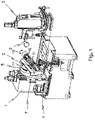
- figure 1 shows a grinding device according to the prior art.
- the axes of a grinding device must be shown for the sake of completeness and understanding.
- a machine stand 1 In the left-hand area of the gear cutting machine, a machine stand 1 is shown, with an object 3 horizontally spaced from it 7 can be moved vertically.
- An installation location 2 of the sensor 8 provided according to the invention can be in the area of the article 3 of the gear cutting machine, which is known per se.
- the description of the invention is both on the figure 1 as well as the following Figures 2 and 3 Referred to, which show the details of the invention, in the representation of the generic device according to figure 1 are not shown.
- the grinding worm 11 When performing the calibration process, make sure that the A axis 6 of the grinding worm 11 is aligned to 0°.
- the grinding worm 11 can be arranged or positioned horizontally, for example, for which purpose it can be pivoted about the A axis 6 accordingly. This offers the advantage that a fixed reference value is available.
- the position of the sensor 8 and its switching point can then be determined automatically.
- the grinding worm 11 is shifted in the Z-direction until the sensor 8 detects the upper part of the grinding mandrel 12. Then it is shifted again until the sensor 8 detects the lower part of the grinding mandrel 12 .
- the sensor height relative to the screw axis can be calculated from these two stored values by averaging.
- the center distance of the sensor 8 to the grinding worm can be determined in a similar way by moving the grinding mandrel 12 vertically until the largest diameter on the grinding mandrel 12 is reached. Since the diameter of the grinding mandrel 12 does not change during processing, the sensor distance from the tool center axis can be calculated using this diameter and the sensor signal.
- How far the sensor 8 is shifted from the center of the machine (workpiece center) in the V direction can be determined as follows: Starting from a specific starting position, the grinding worm 11 is shifted in the V direction until the sensor 8 detects the beginning (the end) of the Grinding worm 11 recorded on the main bearing side (HL). The distance between the main bearing and the grinding worm is known from the design of the grinding mandrel. This V value can be used to calculate how far the sensor 8 is shifted from the center of the machine. In order to determine the switching point of the sensor 8, the center of the grinding worm 11 is moved to the sensor height. The grinding worm 11 is removed from the sensor 8 in the direction of the X-axis 4 and then brought closer again until the sensor 8 detects the grinding mandrel 12 . From this it can be calculated to which value the X-axis 4 must be set so that the switching point of the sensor 8 is between the tooth base and tooth tip of the teeth of the grinding worm 11 .
- the auger width can be calculated from the path difference.
- the method according to the invention also enables the number of flights of the grinding worm 11 to be determined.
- the A axis 6 In order to be able to determine the number of flights, the A axis 6 must also be aligned to 0° here, with 0° meaning a horizontal alignment of the grinding worm 11 .
- the sensor is aligned to the center of the screw and the appropriate switching distance for detecting the screw flights.
- the advantageously optical sensor 8 preferably detects the change in the switching signal during three revolutions of the grinding worm 11 about the B axis 16. Due to the worm pitch and the rotation of the grinding worm, the worm threads move in the V direction and generate a certain number of switching signals. Since the respective teeth each have positive and negative flanks, the respective number of gears of the grinding worm 11 can be determined on the basis of the switching signals. Since two signals are generated for each tooth, the number of switching signals received can be used to determine the number of worm flights. In the case of multi-threaded grinding worms, the number of switching signals is multiplied accordingly. When the grinding worm 11 rotates, a rising tooth flank is referred to as a positive flank and a falling tooth flank is referred to as a negative flank.
- a total of 18 signals can be obtained or measured. These can be derived from the fact that nine teeth are taken into account for three revolutions of the grinding worm 11 and, on the basis of the two signals per tooth, the total number of 18 signals for a 3-flight grinding worm can be deduced. The procedure is the same for a 2-flight grinding worm 11, in which a total of 12 signals can be measured, and for a 1-flight grinding worm 11, in which a total of 6 signals can be measured.
- the centering process is always carried out when the position of the worm threads in relation to the rotary position of the grinding worm 11 is not known to the machine or a corresponding control/regulation of the machine. This is the case, for example, when the grinding worm 11 has been replaced.
- the method according to the invention now offers the possibility of using the optical sensor 8 to measure the grinding worm 11 along its longitudinal axis by moving along the V axis 5 and thus using the machine control to calculate the position of the teeth along the V axis 5 and so on to be able to do without the manual or semi-automatic centering process.
- the grinding worm 11 can thus be automatically centered in the workpiece or relative to the workpiece.
- the pitch is calculated as the path between two switching signals of a rising or falling worm thread flank in connection with the number of worm threads.
- the modulus results from the determined division divided by ⁇ .
- the determination of the incline is also based on a formula according to which the module is multiplied by the gear.
- the sensors can be analog or digital. This must be taken into account when evaluating the measurement signals.
- the method can also be used with other worm-shaped tools, for example in skiving.
- the position of the flutes of the hob and their influence on the signal evaluation must also be taken into account.
- figure 2 shows a schematic representation of the inclined grinding worm 11 with the optical sensor 8.
- the picture shows that in this case the sensor is not mounted over the center of the machine, which means that a mathematical correction calculation is necessary for the calculation as Z correction 9 and V shift 10 is.
- These corrections are preferably taken into account when measuring the number of gears and the number of teeth and when centering.
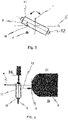
- figure 3 shows a schematic representation of a grinding worm 11 with a grinding mandrel 12 and an article 3 with an arranged optical sensor 8. It can be seen how the inventive arrangement of the optical sensor 8 to the grinding worm 11 is to be realized.
- a laser beam 13 can be emitted by the sensor, in particular along the X-axis 4 .
- the sensor 8 can be arranged between an operator side 15 and an opposite operator side 14 of the gear cutting machine or the object 3 .
Landscapes
- Engineering & Computer Science (AREA)
- Mechanical Engineering (AREA)
- Physics & Mathematics (AREA)
- Optics & Photonics (AREA)
- Human Computer Interaction (AREA)
- Manufacturing & Machinery (AREA)
- General Physics & Mathematics (AREA)
- Automation & Control Theory (AREA)
- Gear Processing (AREA)
- Constituent Portions Of Griding Lathes, Driving, Sensing And Control (AREA)
- Machine Tool Sensing Apparatuses (AREA)
Claims (8)
- Procédé de détermination automatique des dimensions géométriques d'un outil avec une zone d'usinage en forme de spire de vis sans fin, notamment une vis sans fin de meulage, dans une machine à tailler les engrenages, au moins un paramètre de l'outil étant détecté et/ou déterminé automatiquement au moyen d'au moins un capteur (8),
caractérisé en ce que
la position de l'outil à l'intérieur de la machine ainsi que les principales dimensions géométriques, telles que la longueur de l'outil, le diamètre de l'outil et/ou le nombre de spires de l'outil et/ou la direction du pas de l'outil, sont déterminées, et en ce que le pas, le module, le diamètre, la largeur de la vis sans fin, le pas des spires de la vis sans fin et/ou la position en V de l'outil, notamment de la vis sans fin de meulage (11), sont déterminés au moyen d'un traitement par calcul des valeurs détectées et/ou déterminées. - Procédé selon la revendication 1, caractérisé en ce qu'une opération de calibrage est effectuée pour déterminer la position du capteur (8) par rapport à l'outil, notamment à la vis sans fin de meulage (11), et/ou pour le positionnement à l'intérieur de la machine à tailler les engrenages.
- Procédé selon la revendication 1, caractérisé en ce que, pour déterminer le nombre de spires, une orientation de l'outil vers un point de référence prédéfini, de préférence l'orientation de l'axe A à 0°, est effectuée et ensuite le capteur détecte plusieurs rotations, notamment trois rotations, de l'outil, notamment de la vis sans fin de meulage, autour de l'axe B.
- Procédé selon la revendication 1, caractérisé en ce que, pour déterminer la direction du pas, au moins une mesure au moyen du capteur est effectuée au-dessus et au-dessous de l'axe central de l'outil, notamment de la vis sans fin de meulage (11), et/ou l'outil est tourné et la direction du pas est déterminée par déplacement mutuel du capteur (8) et/ou de l'outil dans la direction V.
- Procédé selon l'une quelconque des revendications précédentes, caractérisé en ce que, pour centrer l'outil, notamment la vis sans fin de meulage (11), l'outil est déplacé le long de sa direction d'axe longitudinal ou V ou dans la direction V, la position des dents le long de la direction de l'axe V étant déterminée au moyen du capteur (8).
- Procédé selon l'une quelconque des revendications précédentes, caractérisé en ce que le capteur (8) peut être conçu comme un capteur optique (8), un capteur inductif (8), un capteur capacitif (8) et/ou un capteur à ultrasons (8), le capteur (8) étant un capteur analogique et/ou numérique (8).
- Procédé selon l'une quelconque des revendications précédentes, caractérisé en ce qu'une détermination de différents paramètres pour le centrage automatique de profils asymétriques est effectuée au moyen du capteur.
- Machine à tailler les engrenages avec une commande de machine pour effectuer un procédé selon l'une quelconque des revendications 1 à 7, caractérisée en ce qu'un capteur (8) est prévu sur la machine à tailler les engrenages pour palper une vis sans fin de meulage (11).
Applications Claiming Priority (1)
| Application Number | Priority Date | Filing Date | Title |
|---|---|---|---|
| DE102017000072.7A DE102017000072A1 (de) | 2017-01-05 | 2017-01-05 | Verfahren zum automatischen Bestimmen der geometrischen Abmessungen eines Werkzeuges in einer Verzahnmaschine |
Publications (2)
| Publication Number | Publication Date |
|---|---|
| EP3345707A1 EP3345707A1 (fr) | 2018-07-11 |
| EP3345707B1 true EP3345707B1 (fr) | 2022-10-19 |
Family
ID=60654844
Family Applications (1)
| Application Number | Title | Priority Date | Filing Date |
|---|---|---|---|
| EP17206404.0A Active EP3345707B1 (fr) | 2017-01-05 | 2017-12-11 | Procédé de détermination de manière automatique des dimensions géométriques d'un outil dans une machine à tailler les engrenages |
Country Status (5)
| Country | Link |
|---|---|
| US (1) | US10722994B2 (fr) |
| EP (1) | EP3345707B1 (fr) |
| JP (1) | JP7321665B2 (fr) |
| CN (1) | CN108274303A (fr) |
| DE (1) | DE102017000072A1 (fr) |
Families Citing this family (7)
| Publication number | Priority date | Publication date | Assignee | Title |
|---|---|---|---|---|
| DE102017120788A1 (de) * | 2017-09-08 | 2019-03-14 | Liebherr-Verzahntechnik Gmbh | Verfahren und Vorrichtung zum Wälzschälen |
| DE102017121344A1 (de) * | 2017-09-14 | 2019-03-14 | Liebherr-Verzahntechnik Gmbh | Verfahren zum automatischen Bestimmen der geometrischen Abmessungen eines Werkzeugs mit einem schneckengangförmigen Bearbeitungsbereich |
| EP3511101B1 (fr) | 2018-01-10 | 2020-09-23 | Klingelnberg GmbH | Procédé de vérification d'un outil de meulage et dispositif correspondant |
| CH715989B1 (de) * | 2019-03-22 | 2020-10-30 | Reishauer Ag | Verfahren zum kontinuierlichen Wälzschleifen von vorverzahnten Werkstücken. |
| CH718956A1 (de) * | 2021-09-10 | 2023-03-15 | Reishauer Ag | Werkzeugmaschine mit Kalibriervorrichtung zur Kalibrierung eines Einzentriersensors. |
| CN115431130A (zh) * | 2022-08-25 | 2022-12-06 | 山西光兴光电科技有限公司 | 用于玻璃研磨设备的校正装置和玻璃研磨设备 |
| CN115431102A (zh) * | 2022-09-06 | 2022-12-06 | 浙江力高泵业科技有限公司 | 蜗杆螺纹磨加工成型用精度检测装置及其检测方法 |
Citations (5)
| Publication number | Priority date | Publication date | Assignee | Title |
|---|---|---|---|---|
| DE3827752A1 (de) | 1988-08-16 | 1990-02-22 | Harald Dipl Ing Gosebruch | Verfahren und vorrichtung zur erfassung der oberflaeche von schleifscheiben |
| DE19901338C1 (de) | 1999-01-15 | 2000-03-02 | Reishauer Ag | Verfahren zum Profilieren von schnelldrehenden Schleifschnecken sowie Vorrichtung zur Durchführung des Verfahrens |
| DE19910747A1 (de) | 1999-03-11 | 2000-09-14 | Reishauer Ag | Verfahren und Vorrichtung zum Einmiten eines Abrichtwerkzeuges in die Ganglücke einer Schleifschnecke |
| DE102014007646A1 (de) | 2014-05-23 | 2015-11-26 | Liebherr-Verzahntechnik Gmbh | Verfahren zur Lagebestimmung der Evolventen bei Verzahnungen |
| JP2016078186A (ja) | 2014-10-20 | 2016-05-16 | トーヨーエイテック株式会社 | ネジ状砥石のドレッシング方法 |
Family Cites Families (29)
| Publication number | Priority date | Publication date | Assignee | Title |
|---|---|---|---|---|
| JPS60191744A (ja) * | 1984-03-12 | 1985-09-30 | Makino Furaisu Seiki Kk | スパイラル工具の自動研削用デ−タの検出方法と装置 |
| US5643065A (en) * | 1996-04-12 | 1997-07-01 | Whitesel; Lowell E. | Indexing mechanism for rotatably mounted work holding spindle |
| DE19619401C1 (de) * | 1996-05-14 | 1997-11-27 | Reishauer Ag | Verfahren, Werkzeug und Vorrichtung zum Profilieren von Schleifschnecken für das kontinuierliche Wälzschleifen |
| JPH09314419A (ja) * | 1996-05-27 | 1997-12-09 | Seibu Electric & Mach Co Ltd | 螺子山研磨装置及びその方法 |
| US6491568B1 (en) * | 1997-02-21 | 2002-12-10 | Reishauer Ag | Profiling methods and apparatus for generation of modified grinding worms |
| DE19905136B4 (de) * | 1999-02-09 | 2009-02-12 | Reishauer Ag | Verfahren zum Abrichten einer Schleifschnecke und zum Schleifen vorverzahnter Werkstücke |
| DE19928500B4 (de) * | 1999-06-22 | 2014-04-24 | Reishauer Ag | Verfahren und Vorrichtung zur automatischen Messung von Prozess- und Werkstückkennwerten beim Schleifen von Zahnrädern |
| US6257963B1 (en) * | 2000-05-12 | 2001-07-10 | Reishauer Ag | Grinding worm for the continuous generating grinding of gear wheels |
| DE10012647B4 (de) * | 2000-03-15 | 2009-09-24 | Reishauer Ag | Einrichtverfahren für ein Bearbeitungswerkzeug bzw. Werkstück auf einer Verzahnungsmaschine |
| US6602115B2 (en) * | 2001-01-03 | 2003-08-05 | The Boeing Company | Tool and method for precision grinding of a conical face gear that meshes with a conical involute pinion |
| JP3660920B2 (ja) | 2002-07-01 | 2005-06-15 | オークマ株式会社 | 工作機械および加工方法 |
| DE10240509C5 (de) * | 2002-09-03 | 2017-04-27 | Reishauer Ag | Verzahnungs- und Gewindeschleifmaschine |
| WO2009017248A2 (fr) * | 2007-08-02 | 2009-02-05 | Honda Motor Co., Ltd. | Appareil d'usinage à engrenage et procédé d'usinage |
| DE102008010301A1 (de) * | 2008-02-21 | 2009-09-03 | Liebherr-Verzahntechnik Gmbh | Verfahren zum Betrieb einer Verzahnungsschleifmaschine |
| JP2010117196A (ja) * | 2008-11-12 | 2010-05-27 | Mitsubishi Heavy Ind Ltd | 歯車測定方法 |
| CN102548710A (zh) * | 2009-09-28 | 2012-07-04 | 三菱重工业株式会社 | 螺纹状砂轮的相位对合方法及齿轮磨床 |
| WO2011043225A1 (fr) * | 2009-10-05 | 2011-04-14 | 本田技研工業株式会社 | Dispositif et procédé de mesure d'irrégularité de surface à dents, dispositif et procédé de façonnage d'outil de meulage, et procédé d'appariement de dents pour dispositif de meulage de roue dentée |
| DE102010023728A1 (de) * | 2010-06-14 | 2011-12-15 | Liebherr-Verzahntechnik Gmbh | Verfahren zum Herstellen einer Mehrzahl von identischen Zahnrädern mittles abspanender Bearbeitung |
| DE102011011946A1 (de) * | 2011-02-22 | 2012-09-13 | Liebherr-Verzahntechnik Gmbh | Verfahren zum Vermessen und Prüfen eines Werkstückes und Verzahnmaschine |
| TWI480113B (zh) * | 2011-10-07 | 2015-04-11 | Nat Univ Chung Cheng | 變齒厚蝸桿型刀具及其加工方法 |
| DE102012015846A1 (de) * | 2012-04-17 | 2013-10-17 | Liebherr-Verzahntechnik Gmbh | Verfahren und Vorrichtung zum Hartfeinbearbeiten von modifizierten Verzahnungen |
| DE102014014132A1 (de) * | 2014-09-30 | 2016-05-25 | Liebherr-Verzahntechnik Gmbh | Verfahren und Vorrichtung zum Anfasen und Entgraten verzahnter Werkstücke |
| DE102015000974A1 (de) * | 2015-01-23 | 2016-07-28 | Liebherr-Verzahntechnik Gmbh | Verfahren und Vorrichtung zur Verzahnbearbeitung eines Werkstückes durch ein Diagonalwälzverfahren |
| DE102015008972A1 (de) * | 2015-07-10 | 2017-01-12 | Liebherr-Verzahntechnik Gmbh | Verfahren zur Herstellung eines oder mehrerer Werkstücke |
| DE102015008962A1 (de) * | 2015-07-10 | 2017-01-12 | Liebherr-Verzahntechnik Gmbh | Verfahren zum Abrichten einer mehrgängigen Schleifschnecke |
| DE102015008964A1 (de) * | 2015-07-10 | 2017-01-12 | Liebherr-Verzahntechnik Gmbh | Verfahren zum Abrichten eines Werkzeuges |
| DE102015008963A1 (de) * | 2015-07-10 | 2017-01-12 | Liebherr-Verzahntechnik Gmbh | Verfahren zum Abrichten eines Werkzeuges |
| DE102015012603A1 (de) * | 2015-09-28 | 2017-03-30 | Liebherr-Verzahntechnik Gmbh | Verfahren zum Entgraten eines Zahnradrohlings |
| EP3321628B1 (fr) * | 2016-11-10 | 2020-01-01 | Klingelnberg AG | Dispositif de mesure de coordonnées doté d'un capteur optique et procédé correspondant |
-
2017
- 2017-01-05 DE DE102017000072.7A patent/DE102017000072A1/de active Pending
- 2017-12-11 EP EP17206404.0A patent/EP3345707B1/fr active Active
- 2017-12-26 JP JP2017249468A patent/JP7321665B2/ja active Active
-
2018
- 2018-01-04 US US15/861,912 patent/US10722994B2/en active Active
- 2018-01-05 CN CN201810010927.1A patent/CN108274303A/zh active Pending
Patent Citations (5)
| Publication number | Priority date | Publication date | Assignee | Title |
|---|---|---|---|---|
| DE3827752A1 (de) | 1988-08-16 | 1990-02-22 | Harald Dipl Ing Gosebruch | Verfahren und vorrichtung zur erfassung der oberflaeche von schleifscheiben |
| DE19901338C1 (de) | 1999-01-15 | 2000-03-02 | Reishauer Ag | Verfahren zum Profilieren von schnelldrehenden Schleifschnecken sowie Vorrichtung zur Durchführung des Verfahrens |
| DE19910747A1 (de) | 1999-03-11 | 2000-09-14 | Reishauer Ag | Verfahren und Vorrichtung zum Einmiten eines Abrichtwerkzeuges in die Ganglücke einer Schleifschnecke |
| DE102014007646A1 (de) | 2014-05-23 | 2015-11-26 | Liebherr-Verzahntechnik Gmbh | Verfahren zur Lagebestimmung der Evolventen bei Verzahnungen |
| JP2016078186A (ja) | 2014-10-20 | 2016-05-16 | トーヨーエイテック株式会社 | ネジ状砥石のドレッシング方法 |
Non-Patent Citations (3)
| Title |
|---|
| BYRNE, G. ET AL: "Tool Condition Monitoring (TCM) - The Status of Research and Industrial Application", CIRP ANNALS., ELSEVIER BV, NL, CH, FR, vol. 44, no. 2, 1 January 1995 (1995-01-01), NL, CH, FR , pages 541 - 567, XP022134031, ISSN: 0007-8506, DOI: 10.1016/S0007-8506(07)60503-4 |
| GOSEBRUCH H.: "SCHLEIFSCHEIBEN-GEOMETRIE UND -TOPOGRAPHIE IN ECHTZEIT.", VDI Z, SPRINGER VDI VERLAG, DE, vol. 131., no. 01., 1 January 1989 (1989-01-01), DE , pages 68 - 71., XP000025505, ISSN: 0042-1766 |
| WERNER FRANK: "Hochgeschwindigkeits triangulation zur Verschleißdiagnose an Schleifwerkzeugen", FORTSCHRITT-BERICHTE VDI REIHE 8: MESS-, STEUERUNGS UND REGELUNGSTECHNIK, VDI-VERLAG, vol. Reihe 8, no. 429, 1 January 1994 (1994-01-01), pages 1 - 92, XP093129180 |
Also Published As
| Publication number | Publication date |
|---|---|
| US20180185975A1 (en) | 2018-07-05 |
| CN108274303A (zh) | 2018-07-13 |
| JP2018108640A (ja) | 2018-07-12 |
| EP3345707A1 (fr) | 2018-07-11 |
| JP7321665B2 (ja) | 2023-08-07 |
| US10722994B2 (en) | 2020-07-28 |
| DE102017000072A1 (de) | 2018-07-05 |
Similar Documents
| Publication | Publication Date | Title |
|---|---|---|
| EP3345707B1 (fr) | Procédé de détermination de manière automatique des dimensions géométriques d'un outil dans une machine à tailler les engrenages | |
| DE3150961C2 (de) | Verfahren und Einrichtung zur Bearbeitung eines Zahnrades mittels eines rotierenden, zahnradartigen Werkzeuges | |
| EP3456453A1 (fr) | Procédé et dispositif de taillage | |
| DE102014018328B4 (de) | Verfahren zum bearbeiten einer verzahnung, werkzeuganordnung und verzahnungsmaschine | |
| EP2954967B1 (fr) | Procédé et dispositif de chanfreinage frontal d'une denture d'une pièce à usiner | |
| EP3546101B1 (fr) | Procédé et dispositif servant à tailler des roues d'usinage par décolletage en développante | |
| DE19928500A1 (de) | Verfahren und Vorrichtung zur automatischen Messung von Prozess- und Werkstückkennwerten beim Schleifen von Zahnrädern | |
| DE69932765T2 (de) | Rundbacken-Formwalzvorrichtung | |
| EP3363573B1 (fr) | Dispositif et procédé d'usinage de pièces d'usinage sur une machine à tailler | |
| DE102015008460B4 (de) | System zum Berechnen einer Gewindesteigung | |
| DE102012005228B4 (de) | Verfahren zum spanenden Bearbeiten eines Werkstücks mit einem schneckenförmigen Bearbeitungswerkzeug | |
| EP1319457B1 (fr) | Procédé d'usinage de roues dentées essentiellement cylindriques à denture intérieure ou extérieure | |
| CH714162B1 (de) | Verfahren zum automatischen Bestimmen der geometrischen Abmessungen eines Werkzeugs mit einem schneckengangförmigen Bearbeitungsbereich. | |
| DE10012647A1 (de) | Einrichtverfahren für ein Bearbeitungswerkzeug bzw. Werkstück auf einer Verzahnungsmaschine | |
| DE2604281A1 (de) | Maschine zum schaben und/oder profilrollen der verzahnung von zahnraedern | |
| DE10230148B4 (de) | Verfahren zum Bearbeiten von mittels Wälzfräsen hergestellten Zahnrädern | |
| DE102021132246A1 (de) | Zahnradbearbeitungsverfahren und Zahnradbearbeitungsvorrichtung | |
| DE102008037578A1 (de) | Vorrichtung und Verzahnen von Werkrädern mit einem konischen Wälzfräser | |
| DE102007039959A1 (de) | Verfahren und Profilwalzmaschine zum Kaltwalzen von längsgerichteten Verzahnungen und Profilen bei langen wellenförmigen Werkstücken | |
| DE102013109981A1 (de) | Wälzschälverfahren und zugehörige Vorrichtung | |
| DE102012220125B3 (de) | Rundlaufwerkzeug zur Feinbearbeitung eines Bohrlochs in einem Werkstück sowie Verfahren zur Feinbearbeitung eines Bohrlochs | |
| DE19907363A1 (de) | Topologisches Profilieren von Schleifschnecken für das kontinuierliche Wälzschleifen von Verzahnungen | |
| EP4093571B1 (fr) | Procédé pour usiner une pièce présentant deux dentures, dispositif de positionnement pour déterminer une position d'angle de rotation de référence de la pièce et machine-outil équipée d'un tel dispositif de positionnement | |
| DE3402429A1 (de) | Vorrichtung zum selbsttaetigen positionieren eines verzahnungs- oder nutenfraesers in bezug auf eine bereits vorhandene verzahnung oder nutung | |
| DE102012012174A1 (de) | Verfahren zum Kompensieren einer Werkzeugrundlaufabweichung |
Legal Events
| Date | Code | Title | Description |
|---|---|---|---|
| PUAI | Public reference made under article 153(3) epc to a published international application that has entered the european phase |
Free format text: ORIGINAL CODE: 0009012 |
|
| STAA | Information on the status of an ep patent application or granted ep patent |
Free format text: STATUS: THE APPLICATION HAS BEEN PUBLISHED |
|
| AK | Designated contracting states |
Kind code of ref document: A1 Designated state(s): AL AT BE BG CH CY CZ DE DK EE ES FI FR GB GR HR HU IE IS IT LI LT LU LV MC MK MT NL NO PL PT RO RS SE SI SK SM TR |
|
| AX | Request for extension of the european patent |
Extension state: BA ME |
|
| STAA | Information on the status of an ep patent application or granted ep patent |
Free format text: STATUS: REQUEST FOR EXAMINATION WAS MADE |
|
| 17P | Request for examination filed |
Effective date: 20190110 |
|
| STAA | Information on the status of an ep patent application or granted ep patent |
Free format text: STATUS: REQUEST FOR EXAMINATION WAS MADE |
|
| STAA | Information on the status of an ep patent application or granted ep patent |
Free format text: STATUS: EXAMINATION IS IN PROGRESS |
|
| STAA | Information on the status of an ep patent application or granted ep patent |
Free format text: STATUS: EXAMINATION IS IN PROGRESS |
|
| 17Q | First examination report despatched |
Effective date: 20211116 |
|
| GRAP | Despatch of communication of intention to grant a patent |
Free format text: ORIGINAL CODE: EPIDOSNIGR1 |
|
| STAA | Information on the status of an ep patent application or granted ep patent |
Free format text: STATUS: GRANT OF PATENT IS INTENDED |
|
| INTG | Intention to grant announced |
Effective date: 20220704 |
|
| GRAS | Grant fee paid |
Free format text: ORIGINAL CODE: EPIDOSNIGR3 |
|
| GRAA | (expected) grant |
Free format text: ORIGINAL CODE: 0009210 |
|
| STAA | Information on the status of an ep patent application or granted ep patent |
Free format text: STATUS: THE PATENT HAS BEEN GRANTED |
|
| AK | Designated contracting states |
Kind code of ref document: B1 Designated state(s): AL AT BE BG CH CY CZ DE DK EE ES FI FR GB GR HR HU IE IS IT LI LT LU LV MC MK MT NL NO PL PT RO RS SE SI SK SM TR |
|
| REG | Reference to a national code |
Ref country code: GB Ref legal event code: FG4D Free format text: NOT ENGLISH |
|
| REG | Reference to a national code |
Ref country code: CH Ref legal event code: EP |
|
| REG | Reference to a national code |
Ref country code: DE Ref legal event code: R096 Ref document number: 502017013972 Country of ref document: DE |
|
| REG | Reference to a national code |
Ref country code: IE Ref legal event code: FG4D Free format text: LANGUAGE OF EP DOCUMENT: GERMAN |
|
| REG | Reference to a national code |
Ref country code: AT Ref legal event code: REF Ref document number: 1525255 Country of ref document: AT Kind code of ref document: T Effective date: 20221115 |
|
| REG | Reference to a national code |
Ref country code: LT Ref legal event code: MG9D |
|
| REG | Reference to a national code |
Ref country code: NL Ref legal event code: MP Effective date: 20221019 |
|
| PG25 | Lapsed in a contracting state [announced via postgrant information from national office to epo] |
Ref country code: NL Free format text: LAPSE BECAUSE OF FAILURE TO SUBMIT A TRANSLATION OF THE DESCRIPTION OR TO PAY THE FEE WITHIN THE PRESCRIBED TIME-LIMIT Effective date: 20221019 |
|
| PG25 | Lapsed in a contracting state [announced via postgrant information from national office to epo] |
Ref country code: SE Free format text: LAPSE BECAUSE OF FAILURE TO SUBMIT A TRANSLATION OF THE DESCRIPTION OR TO PAY THE FEE WITHIN THE PRESCRIBED TIME-LIMIT Effective date: 20221019 Ref country code: PT Free format text: LAPSE BECAUSE OF FAILURE TO SUBMIT A TRANSLATION OF THE DESCRIPTION OR TO PAY THE FEE WITHIN THE PRESCRIBED TIME-LIMIT Effective date: 20230220 Ref country code: NO Free format text: LAPSE BECAUSE OF FAILURE TO SUBMIT A TRANSLATION OF THE DESCRIPTION OR TO PAY THE FEE WITHIN THE PRESCRIBED TIME-LIMIT Effective date: 20230119 Ref country code: LT Free format text: LAPSE BECAUSE OF FAILURE TO SUBMIT A TRANSLATION OF THE DESCRIPTION OR TO PAY THE FEE WITHIN THE PRESCRIBED TIME-LIMIT Effective date: 20221019 Ref country code: FI Free format text: LAPSE BECAUSE OF FAILURE TO SUBMIT A TRANSLATION OF THE DESCRIPTION OR TO PAY THE FEE WITHIN THE PRESCRIBED TIME-LIMIT Effective date: 20221019 Ref country code: ES Free format text: LAPSE BECAUSE OF FAILURE TO SUBMIT A TRANSLATION OF THE DESCRIPTION OR TO PAY THE FEE WITHIN THE PRESCRIBED TIME-LIMIT Effective date: 20221019 |
|
| PG25 | Lapsed in a contracting state [announced via postgrant information from national office to epo] |
Ref country code: RS Free format text: LAPSE BECAUSE OF FAILURE TO SUBMIT A TRANSLATION OF THE DESCRIPTION OR TO PAY THE FEE WITHIN THE PRESCRIBED TIME-LIMIT Effective date: 20221019 Ref country code: PL Free format text: LAPSE BECAUSE OF FAILURE TO SUBMIT A TRANSLATION OF THE DESCRIPTION OR TO PAY THE FEE WITHIN THE PRESCRIBED TIME-LIMIT Effective date: 20221019 Ref country code: LV Free format text: LAPSE BECAUSE OF FAILURE TO SUBMIT A TRANSLATION OF THE DESCRIPTION OR TO PAY THE FEE WITHIN THE PRESCRIBED TIME-LIMIT Effective date: 20221019 Ref country code: IS Free format text: LAPSE BECAUSE OF FAILURE TO SUBMIT A TRANSLATION OF THE DESCRIPTION OR TO PAY THE FEE WITHIN THE PRESCRIBED TIME-LIMIT Effective date: 20230219 Ref country code: HR Free format text: LAPSE BECAUSE OF FAILURE TO SUBMIT A TRANSLATION OF THE DESCRIPTION OR TO PAY THE FEE WITHIN THE PRESCRIBED TIME-LIMIT Effective date: 20221019 Ref country code: GR Free format text: LAPSE BECAUSE OF FAILURE TO SUBMIT A TRANSLATION OF THE DESCRIPTION OR TO PAY THE FEE WITHIN THE PRESCRIBED TIME-LIMIT Effective date: 20230120 |
|
| REG | Reference to a national code |
Ref country code: DE Ref legal event code: R026 Ref document number: 502017013972 Country of ref document: DE |
|
| PLBI | Opposition filed |
Free format text: ORIGINAL CODE: 0009260 |
|
| PG25 | Lapsed in a contracting state [announced via postgrant information from national office to epo] |
Ref country code: SM Free format text: LAPSE BECAUSE OF FAILURE TO SUBMIT A TRANSLATION OF THE DESCRIPTION OR TO PAY THE FEE WITHIN THE PRESCRIBED TIME-LIMIT Effective date: 20221019 Ref country code: RO Free format text: LAPSE BECAUSE OF FAILURE TO SUBMIT A TRANSLATION OF THE DESCRIPTION OR TO PAY THE FEE WITHIN THE PRESCRIBED TIME-LIMIT Effective date: 20221019 Ref country code: EE Free format text: LAPSE BECAUSE OF FAILURE TO SUBMIT A TRANSLATION OF THE DESCRIPTION OR TO PAY THE FEE WITHIN THE PRESCRIBED TIME-LIMIT Effective date: 20221019 Ref country code: DK Free format text: LAPSE BECAUSE OF FAILURE TO SUBMIT A TRANSLATION OF THE DESCRIPTION OR TO PAY THE FEE WITHIN THE PRESCRIBED TIME-LIMIT Effective date: 20221019 Ref country code: CZ Free format text: LAPSE BECAUSE OF FAILURE TO SUBMIT A TRANSLATION OF THE DESCRIPTION OR TO PAY THE FEE WITHIN THE PRESCRIBED TIME-LIMIT Effective date: 20221019 |
|
| PLAX | Notice of opposition and request to file observation + time limit sent |
Free format text: ORIGINAL CODE: EPIDOSNOBS2 |
|
| 26 | Opposition filed |
Opponent name: REISHAUER AG Effective date: 20230718 |
|
| REG | Reference to a national code |
Ref country code: BE Ref legal event code: MM Effective date: 20221231 |
|
| PG25 | Lapsed in a contracting state [announced via postgrant information from national office to epo] |
Ref country code: SK Free format text: LAPSE BECAUSE OF FAILURE TO SUBMIT A TRANSLATION OF THE DESCRIPTION OR TO PAY THE FEE WITHIN THE PRESCRIBED TIME-LIMIT Effective date: 20221019 Ref country code: LU Free format text: LAPSE BECAUSE OF NON-PAYMENT OF DUE FEES Effective date: 20221211 Ref country code: AL Free format text: LAPSE BECAUSE OF FAILURE TO SUBMIT A TRANSLATION OF THE DESCRIPTION OR TO PAY THE FEE WITHIN THE PRESCRIBED TIME-LIMIT Effective date: 20221019 |
|
| GBPC | Gb: european patent ceased through non-payment of renewal fee |
Effective date: 20230119 |
|
| PG25 | Lapsed in a contracting state [announced via postgrant information from national office to epo] |
Ref country code: IE Free format text: LAPSE BECAUSE OF NON-PAYMENT OF DUE FEES Effective date: 20221211 Ref country code: GB Free format text: LAPSE BECAUSE OF NON-PAYMENT OF DUE FEES Effective date: 20230119 |
|
| PG25 | Lapsed in a contracting state [announced via postgrant information from national office to epo] |
Ref country code: SI Free format text: LAPSE BECAUSE OF FAILURE TO SUBMIT A TRANSLATION OF THE DESCRIPTION OR TO PAY THE FEE WITHIN THE PRESCRIBED TIME-LIMIT Effective date: 20221019 Ref country code: FR Free format text: LAPSE BECAUSE OF NON-PAYMENT OF DUE FEES Effective date: 20221219 Ref country code: BE Free format text: LAPSE BECAUSE OF NON-PAYMENT OF DUE FEES Effective date: 20221231 |
|
| PLBB | Reply of patent proprietor to notice(s) of opposition received |
Free format text: ORIGINAL CODE: EPIDOSNOBS3 |
|
| PGFP | Annual fee paid to national office [announced via postgrant information from national office to epo] |
Ref country code: IT Payment date: 20231227 Year of fee payment: 7 |
|
| REG | Reference to a national code |
Ref country code: AT Ref legal event code: MM01 Ref document number: 1525255 Country of ref document: AT Kind code of ref document: T Effective date: 20221211 |
|
| PG25 | Lapsed in a contracting state [announced via postgrant information from national office to epo] |
Ref country code: HU Free format text: LAPSE BECAUSE OF FAILURE TO SUBMIT A TRANSLATION OF THE DESCRIPTION OR TO PAY THE FEE WITHIN THE PRESCRIBED TIME-LIMIT; INVALID AB INITIO Effective date: 20171211 |
|
| PG25 | Lapsed in a contracting state [announced via postgrant information from national office to epo] |
Ref country code: AT Free format text: LAPSE BECAUSE OF NON-PAYMENT OF DUE FEES Effective date: 20221211 |
|
| PG25 | Lapsed in a contracting state [announced via postgrant information from national office to epo] |
Ref country code: CY Free format text: LAPSE BECAUSE OF FAILURE TO SUBMIT A TRANSLATION OF THE DESCRIPTION OR TO PAY THE FEE WITHIN THE PRESCRIBED TIME-LIMIT Effective date: 20221019 Ref country code: AT Free format text: LAPSE BECAUSE OF NON-PAYMENT OF DUE FEES Effective date: 20221211 |
|
| PGFP | Annual fee paid to national office [announced via postgrant information from national office to epo] |
Ref country code: DE Payment date: 20231221 Year of fee payment: 7 Ref country code: CH Payment date: 20240101 Year of fee payment: 7 |