EP3345636B1 - Dispositif de retrait et de stockage de pointe d'aiguille et leurs procédés de fabrication - Google Patents
Dispositif de retrait et de stockage de pointe d'aiguille et leurs procédés de fabrication Download PDFInfo
- Publication number
- EP3345636B1 EP3345636B1 EP18158443.4A EP18158443A EP3345636B1 EP 3345636 B1 EP3345636 B1 EP 3345636B1 EP 18158443 A EP18158443 A EP 18158443A EP 3345636 B1 EP3345636 B1 EP 3345636B1
- Authority
- EP
- European Patent Office
- Prior art keywords
- needle tip
- removal
- storage compartment
- storage
- housing
- Prior art date
- Legal status (The legal status is an assumption and is not a legal conclusion. Google has not performed a legal analysis and makes no representation as to the accuracy of the status listed.)
- Active
Links
- 238000003860 storage Methods 0.000 title claims description 148
- 238000000034 method Methods 0.000 title claims description 25
- 238000004519 manufacturing process Methods 0.000 title description 5
- 239000000463 material Substances 0.000 claims description 14
- 238000003466 welding Methods 0.000 claims description 9
- 230000001954 sterilising effect Effects 0.000 claims description 5
- 238000002347 injection Methods 0.000 claims description 4
- 239000007924 injection Substances 0.000 claims description 4
- 238000004659 sterilization and disinfection Methods 0.000 claims description 4
- 238000004026 adhesive bonding Methods 0.000 claims description 2
- 239000011888 foil Substances 0.000 description 9
- 229940090048 pen injector Drugs 0.000 description 5
- 238000000465 moulding Methods 0.000 description 3
- 230000005855 radiation Effects 0.000 description 3
- 238000003780 insertion Methods 0.000 description 2
- 230000037431 insertion Effects 0.000 description 2
- 229920003023 plastic Polymers 0.000 description 2
- 239000004033 plastic Substances 0.000 description 2
- 238000009516 primary packaging Methods 0.000 description 2
- 230000002441 reversible effect Effects 0.000 description 2
- 238000007789 sealing Methods 0.000 description 2
- 208000012266 Needlestick injury Diseases 0.000 description 1
- 239000000853 adhesive Substances 0.000 description 1
- 230000001070 adhesive effect Effects 0.000 description 1
- 230000015572 biosynthetic process Effects 0.000 description 1
- 229940079593 drug Drugs 0.000 description 1
- 239000003814 drug Substances 0.000 description 1
- 239000012467 final product Substances 0.000 description 1
- 238000005755 formation reaction Methods 0.000 description 1
- 230000036512 infertility Effects 0.000 description 1
- 238000001746 injection moulding Methods 0.000 description 1
Images


Classifications
-
- A—HUMAN NECESSITIES
- A61—MEDICAL OR VETERINARY SCIENCE; HYGIENE
- A61M—DEVICES FOR INTRODUCING MEDIA INTO, OR ONTO, THE BODY; DEVICES FOR TRANSDUCING BODY MEDIA OR FOR TAKING MEDIA FROM THE BODY; DEVICES FOR PRODUCING OR ENDING SLEEP OR STUPOR
- A61M5/00—Devices for bringing media into the body in a subcutaneous, intra-vascular or intramuscular way; Accessories therefor, e.g. filling or cleaning devices, arm-rests
- A61M5/178—Syringes
- A61M5/31—Details
- A61M5/32—Needles; Details of needles pertaining to their connection with syringe or hub; Accessories for bringing the needle into, or holding the needle on, the body; Devices for protection of needles
- A61M5/3205—Apparatus for removing or disposing of used needles or syringes, e.g. containers; Means for protection against accidental injuries from used needles
-
- A—HUMAN NECESSITIES
- A61—MEDICAL OR VETERINARY SCIENCE; HYGIENE
- A61M—DEVICES FOR INTRODUCING MEDIA INTO, OR ONTO, THE BODY; DEVICES FOR TRANSDUCING BODY MEDIA OR FOR TAKING MEDIA FROM THE BODY; DEVICES FOR PRODUCING OR ENDING SLEEP OR STUPOR
- A61M5/00—Devices for bringing media into the body in a subcutaneous, intra-vascular or intramuscular way; Accessories therefor, e.g. filling or cleaning devices, arm-rests
- A61M5/178—Syringes
- A61M5/31—Details
- A61M5/32—Needles; Details of needles pertaining to their connection with syringe or hub; Accessories for bringing the needle into, or holding the needle on, the body; Devices for protection of needles
- A61M5/3202—Devices for protection of the needle before use, e.g. caps
-
- A—HUMAN NECESSITIES
- A61—MEDICAL OR VETERINARY SCIENCE; HYGIENE
- A61M—DEVICES FOR INTRODUCING MEDIA INTO, OR ONTO, THE BODY; DEVICES FOR TRANSDUCING BODY MEDIA OR FOR TAKING MEDIA FROM THE BODY; DEVICES FOR PRODUCING OR ENDING SLEEP OR STUPOR
- A61M5/00—Devices for bringing media into the body in a subcutaneous, intra-vascular or intramuscular way; Accessories therefor, e.g. filling or cleaning devices, arm-rests
- A61M5/002—Packages specially adapted therefor, e.g. for syringes or needles, kits for diabetics
-
- A—HUMAN NECESSITIES
- A61—MEDICAL OR VETERINARY SCIENCE; HYGIENE
- A61M—DEVICES FOR INTRODUCING MEDIA INTO, OR ONTO, THE BODY; DEVICES FOR TRANSDUCING BODY MEDIA OR FOR TAKING MEDIA FROM THE BODY; DEVICES FOR PRODUCING OR ENDING SLEEP OR STUPOR
- A61M5/00—Devices for bringing media into the body in a subcutaneous, intra-vascular or intramuscular way; Accessories therefor, e.g. filling or cleaning devices, arm-rests
- A61M5/178—Syringes
- A61M5/31—Details
- A61M5/32—Needles; Details of needles pertaining to their connection with syringe or hub; Accessories for bringing the needle into, or holding the needle on, the body; Devices for protection of needles
- A61M5/3205—Apparatus for removing or disposing of used needles or syringes, e.g. containers; Means for protection against accidental injuries from used needles
- A61M5/321—Means for protection against accidental injuries by used needles
- A61M5/3213—Caps placed axially onto the needle, e.g. equipped with finger protection guards
-
- A—HUMAN NECESSITIES
- A61—MEDICAL OR VETERINARY SCIENCE; HYGIENE
- A61M—DEVICES FOR INTRODUCING MEDIA INTO, OR ONTO, THE BODY; DEVICES FOR TRANSDUCING BODY MEDIA OR FOR TAKING MEDIA FROM THE BODY; DEVICES FOR PRODUCING OR ENDING SLEEP OR STUPOR
- A61M5/00—Devices for bringing media into the body in a subcutaneous, intra-vascular or intramuscular way; Accessories therefor, e.g. filling or cleaning devices, arm-rests
- A61M5/178—Syringes
- A61M5/31—Details
- A61M5/32—Needles; Details of needles pertaining to their connection with syringe or hub; Accessories for bringing the needle into, or holding the needle on, the body; Devices for protection of needles
- A61M5/3205—Apparatus for removing or disposing of used needles or syringes, e.g. containers; Means for protection against accidental injuries from used needles
- A61M5/321—Means for protection against accidental injuries by used needles
- A61M5/3216—Caps placed transversally onto the needle, e.g. pivotally attached to the needle base
-
- A—HUMAN NECESSITIES
- A61—MEDICAL OR VETERINARY SCIENCE; HYGIENE
- A61M—DEVICES FOR INTRODUCING MEDIA INTO, OR ONTO, THE BODY; DEVICES FOR TRANSDUCING BODY MEDIA OR FOR TAKING MEDIA FROM THE BODY; DEVICES FOR PRODUCING OR ENDING SLEEP OR STUPOR
- A61M5/00—Devices for bringing media into the body in a subcutaneous, intra-vascular or intramuscular way; Accessories therefor, e.g. filling or cleaning devices, arm-rests
- A61M5/178—Syringes
- A61M5/31—Details
- A61M5/32—Needles; Details of needles pertaining to their connection with syringe or hub; Accessories for bringing the needle into, or holding the needle on, the body; Devices for protection of needles
- A61M5/3205—Apparatus for removing or disposing of used needles or syringes, e.g. containers; Means for protection against accidental injuries from used needles
- A61M5/3276—Means imparting rotational movement to the needle or needle hub in order to assist in its disconnection from syringe nozzle
-
- B—PERFORMING OPERATIONS; TRANSPORTING
- B65—CONVEYING; PACKING; STORING; HANDLING THIN OR FILAMENTARY MATERIAL
- B65B—MACHINES, APPARATUS OR DEVICES FOR, OR METHODS OF, PACKAGING ARTICLES OR MATERIALS; UNPACKING
- B65B5/00—Packaging individual articles in containers or receptacles, e.g. bags, sacks, boxes, cartons, cans, jars
- B65B5/02—Machines characterised by incorporation of means for making the containers or receptacles
-
- B—PERFORMING OPERATIONS; TRANSPORTING
- B65—CONVEYING; PACKING; STORING; HANDLING THIN OR FILAMENTARY MATERIAL
- B65B—MACHINES, APPARATUS OR DEVICES FOR, OR METHODS OF, PACKAGING ARTICLES OR MATERIALS; UNPACKING
- B65B55/00—Preserving, protecting or purifying packages or package contents in association with packaging
- B65B55/02—Sterilising, e.g. of complete packages
- B65B55/04—Sterilising wrappers or receptacles prior to, or during, packaging
- B65B55/08—Sterilising wrappers or receptacles prior to, or during, packaging by irradiation
-
- B—PERFORMING OPERATIONS; TRANSPORTING
- B65—CONVEYING; PACKING; STORING; HANDLING THIN OR FILAMENTARY MATERIAL
- B65B—MACHINES, APPARATUS OR DEVICES FOR, OR METHODS OF, PACKAGING ARTICLES OR MATERIALS; UNPACKING
- B65B7/00—Closing containers or receptacles after filling
- B65B7/16—Closing semi-rigid or rigid containers or receptacles not deformed by, or not taking-up shape of, contents, e.g. boxes or cartons
- B65B7/28—Closing semi-rigid or rigid containers or receptacles not deformed by, or not taking-up shape of, contents, e.g. boxes or cartons by applying separate preformed closures, e.g. lids, covers
-
- A—HUMAN NECESSITIES
- A61—MEDICAL OR VETERINARY SCIENCE; HYGIENE
- A61M—DEVICES FOR INTRODUCING MEDIA INTO, OR ONTO, THE BODY; DEVICES FOR TRANSDUCING BODY MEDIA OR FOR TAKING MEDIA FROM THE BODY; DEVICES FOR PRODUCING OR ENDING SLEEP OR STUPOR
- A61M5/00—Devices for bringing media into the body in a subcutaneous, intra-vascular or intramuscular way; Accessories therefor, e.g. filling or cleaning devices, arm-rests
- A61M5/178—Syringes
- A61M5/31—Details
- A61M5/32—Needles; Details of needles pertaining to their connection with syringe or hub; Accessories for bringing the needle into, or holding the needle on, the body; Devices for protection of needles
- A61M5/3205—Apparatus for removing or disposing of used needles or syringes, e.g. containers; Means for protection against accidental injuries from used needles
- A61M2005/3208—Apparatus for removing or disposing of used needles or syringes, e.g. containers; Means for protection against accidental injuries from used needles by application of rotational movement to the needle hub, e.g. by use of electrically driven toothed wheels
-
- A—HUMAN NECESSITIES
- A61—MEDICAL OR VETERINARY SCIENCE; HYGIENE
- A61M—DEVICES FOR INTRODUCING MEDIA INTO, OR ONTO, THE BODY; DEVICES FOR TRANSDUCING BODY MEDIA OR FOR TAKING MEDIA FROM THE BODY; DEVICES FOR PRODUCING OR ENDING SLEEP OR STUPOR
- A61M2207/00—Methods of manufacture, assembly or production
Definitions
- This invention relates to needle tip storage and removal devices and to methods of manufacture thereof.
- Many drugs that need to be injected regularly are delivered by a pen injector or the like (such as our Autopen® injector) which has a removable and disposable needle tip (or "pen tip") which is screwed and unscrewed or otherwise attached and detached by rotary action to the front end of the pen injector to provide a fresh needle for each injection.
- a typical needle tip is our UniFine® needle tip. This comprises an internally threaded cylindrical hub typically of a plastics material and having a fluted or splined outer cylindrical surface. A needle projects axially forwardly of the hub.
- the storage container has internal splines which engage the external splines on the outer cylindrical surface of the needle tip.
- the storage container can therefore be used as a spanner or wrench to screw the needle tip into engagement with a threaded portion on the pen injector where this is provided and which can be slid on or off the needle tip.
- the storage container may provide a similar function in other types of rotary connection. It is preferred that the user, having applied a needle tip to a pen injector and withdrawn the needle tip container to expose the needle tip, should keep the container safe so that it can be used to re-cover the needle. This is so that the container can be used again as a spanner or wrench to unscrew it from the pen injector and then to allow safe disposal of the used needle tip inside the storage container, and also so that the needle is safely covered as the needle tip is being unscrewed.
- GB2437923 is designed to address this problem and provides a needle tip storage and removal device having opposed, oppositely directed storage and removal compartments, intended to be moulded in one piece in an injection moulding process.
- the integrally formed removal compartment are typically made of a material which is puncture resistant. The puncture resistance material tends to be thicker and so increases the amount of material used which is undesirable for a disposable item.
- a needle tip storage and removal device which allows the materials for the storage compartment to be optimised having regard to the requirements of that compartment, that is (maintaining sterility and ease of sterilisation by radiation and the materials of the removal tool to be optimised for its purpose, typically good puncture resistance and good resilience, economy of production and disposability.
- a needle tip storage and removal device for use with a needle tip comprising a needle hub and a needle extending axially therefrom, which includes:
- the hub of said needle tip is generally cylindrical, and said needle tip and said storage compartment are configured to allow said needle tip to be slid into and out of non-rotatable engagement with said removal housing.
- said removal housing is adapted to receive a used needle tip in non-rotatable engagement, when inserted therein.
- said removal housing is configured to receive a needle tip inserted in a direction transverse to said axis.
- said removal housing is adapted to receive a used needle tip when inserted in a direction generally parallel or coincident with said axis.
- said removal housing includes a snap fit engagement arrangement to prevent or resist removal of a used needle tip once inserted into said removal housing.
- said removal housing shrouds the needle of a used needle tip when inserted into said housing, and advantageously said housing fully encloses the needle of said used needle tip.
- the storage container has an outer shape including a larger cylindrical portion and a smaller cylindrical portion interconnected by a bridging portion.
- said removal housing includes at least one ring-shaped portion adapted to surround and secure a portion of the storage container.
- said removal housing includes a spaced ring-shaped portion adapted to surround and secure a further respective spaced portion of said storage compartment.
- each said ring-shaped portion is secured to an adjacent portion of said storage compartment by one or more of: heat welding, ultrasonic welding, adhesive bonding, snap action and mechanical interlock.
- said removal housing includes at least one clip portion adapted to clip around a portion of said storage compartment to secure said removal housing to said storage compartment.
- said removal housing includes two spaced clip portions adapted to clip around respective spaced portions of said storage compartment, to secure said removal housing to said storage compartment.
- said removal housing comprises a larger cylindrical portion merging with a frusto-conical portion which merges with a smaller cylindrical portion.
- said removal housing includes a recess for receiving and locating opposed longitudinal end portions of said storage compartment.
- said removal housing is formed by overmoulding a material over at least a portion of said storage compartment, thereby to provide a removal housing connected around said storage compartment.
- said storage compartment and said removal housing each define respective holding portions for the needle tip such that a needle tip held in the storage compartment is held with its needle extending generally parallel to and facing in the opposite direction to a needle tip held in the removal housing.
- the invention provides a needle tip storage and removal device for use with a needle tip comprising a cylindrical hub and a needle extending axially therefrom, which comprises a storage compartment formed in a given forming process for containing a needle tip in a sterile environment and for being sealed by an openable seal element, a separately formed outer housing having a recess adapted to receive said storage compartment, and a closure element configured to be moveable between a retracted position in which access to the interior of said storage compartment is allowed, and a closed position in which such access is prevented or inhibited.
- said storage compartment defines an interior recess into which a needle tip may be inserted for non-rotatable engagement
- said outer housing defines a stepped recess having a larger diameter cylindrical portion for receiving said storage compartment and, beyond said larger diameter cylindrical portion, a smaller diameter cylindrical portion into which a needle tip may be inserted for non-rotatable engagement if the larger diameter cylindrical recess is not occupied by a storage compartment.
- said storage compartment includes a removable seal element, and said outer housing and/or said closure element are configured so that the said seal element, if present on said storage compartment, blocks movement of said closure element to its closed position, but when said seal element is absent said closure element may be moved to its closed position.
- the invention provides a method of producing a needle tip storage and removal device which comprises:
- said storage compartment and said removal tool are formed of different materials.
- the method may further include the step of inserting a needle tip into said storage compartment and applying a closure element to said compartment hermetically to seal the needle tip in said storage compartment.
- the method may further include the step of sterilising the assembly of the needle tip and the storage compartment.
- said step of sterilisation includes irradiation.
- said removal tool comprises a recess for receiving said needle tip.
- said removal tool is joined to said storage compartment by at least one of the following methods:
- said storage compartment and said removal tool are joined together by forming the removal tool around said storage compartment.
- said removal tool is formed by overmoulding said storage compartment.
- the storage compartment and the removal tool are joined together by forming a removal tool having a recess for receiving the storage compartment and thereafter inserting said storage compartment into said recess.
- the various embodiments described herein provide needle tip storage and removal devices made up of a storage container or compartment containing a needle tip and hermetically sealed by a removable foil or the like, the needle tip container then being assembled with a removal housing which is or has been formed in a separate forming step.
- the needle tip storage and removal device may be made by taking a pre-existing needle tip container sealed with the needle tip inside it, and then assembling it with the removal housing.
- the moulding of the storage container, loading of the needle tip and subsequent sealing of the container may be optimised for subsequent sterilisation process by gamma irradiation prior to assembly with the removal housing.
- the sterile needle tip storage container, with needle tip inside may then be assembled in a sterile manner with the removal housing.
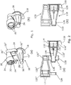
- the needle tip storage container is made up of a relatively large diameter portion 10 1 , which merges with a frustoconical portion 10 2 which itself merges with a closed tip portion 10 3 of relative small diameter, as seen for example in Figures 1(a) , 5(a) and 10(b) .
- the larger cylindrical portion defines an internal cylindrical wall with splines 22 equi-spaced around it, the splines being designed to allow the needle tip hub to be slid into and out of non-rotatable engagement with the needle tip storage container.
- the needle tip has a double ended needle (see Figure 2(a) ).
- the needle tip storage container 10 is sealed by a removable foil 18.
- the needle tip removal housing 20 is formed in a separate process and from, typically, different materials but has a similar overall shape and internal shape as that of the needle tip storage container 10.
- the needle tip removal housing 20 has a relatively large diameter portion 20 1 that merges with a frustoconical portion 20 2 which itself merges with a cylindrical tip portion 20 3 .
- the large cylindrical portion 20 1 is provided with splines 22 into which a used needle tip may be slid in non-rotatable engagement.
- the open end of the larger diameter cylindrical portion 20 1 is provided with an internal snap rib 24 designed to lock a used needle tip in the removal housing 20 when it is fully pushed home.
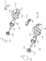
- the needle tip removal housing is provided with laterally extending small and large ring portions 126 and 128 respectively.
- the needle tip storage container is provided with small and large diameter snap rings 130, 132 on the external surface of the small and large diameter cylindrical portions 110 3 and 110 1 .
- the needle tip storage container and the needle tip removal housing may be assembled together by disposing them in the position of Figure 2(a) and then bringing them together so that the ribs 130, 132 squeeze through and snap through the ring shaped portions 126 and 128, as seen in Figure 2(b) .
- the small and large diameter portions of the needle tip storage container 210 are formed with annular ribs 230 and 232.
- the needle tip storage container 210 and the needle tip removal housing 220 are positioned as shown in Figure 3 and then pushed together so that the annular ribs 230 and 232 contact and pass into the inner cylindrical surface of rings 226, 228 on the needle tip removal housing 220.
- An ultrasonic welding process is then applied to cause the ribs 230 and 232 to fuse or melt with surrounding ring portion 226, 228 permanently to secure the needle tip storage container and the needle tip removal housing together.
- the needle tip storage container 310 is provided with annular recesses 330 and 332 in its small and large diameter portions respectively.
- the needle tip removal housing 320 is identical to that of the fourth embodiment and the needle tip storage container and the needle tip removal housing are assembled together by applying an adhesive to the grooves 330 and 332 and then assembling the two together as shown in Figure 4(b) .
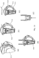
- a needle tip storage container 410 similar to that of the previous embodiment, containing a needle tip of the type described above and sealed by a foil 418 is provided with a tab 420 that extends transversely from a flange 422 provided at the open end of the larger cylindrical portion of the needle tip storage container.
- the flange 422 provides a planar radial surface to which the foil 418 is heat-sealed.
- the tab 420 is formed integrally in the same moulding process as the main portion of the needle tip storage container 410.
- the needle tip removal housing is based on our existing UniGuard® device, as described in WO 2005/102424 .
- the needle tip removal housing 426 has an opening 428 of outline generally matching and adapted to receive the hub 414 and needle 416 of a needle tip when inserted laterally.
- the opening includes a U-shaped cradle portion 428 which has two abutments 430 past which the needle hub snaps when inserted laterally. Once in its fully home position, the needle hub engages splines (not shown) on the interior of the U-shaped portion 428 to engage it non-rotatably.
- the needle removal housing 426 is provided with a recess 434 into which the tab 420 on the flange of the needle tip storage container be snapped irreversibly.
- Snapping the tab 420 into the recess 434 holds the needle tip storage container closely against the underside of the needle tip removal housing 426, with portions thereof cradled by supports 436, 438 and the smaller diameter end of the needle housing is provided with a dished portion 440 over into the edge of which hooks a protrusion 442 to hold the needle tip storage container and the needle tip removal housing securely together.
- a two-shot or overmoulding process is used to initially form a needle tip storage container 510 of similar form to those of the earlier embodiments which can then be fitted with a needle tip sealed and then sterilised.
- a needle tip removal housing 520 is moulded which has a main needle tip receiving portion with an integral frame structure embracing and connecting the needle tip storage container.
- the needle tip removal portion may include flexible tabs 522 to prevent removal of a used needle tip once inserted into the needle tip removal portion.
- the needle tip removal portion has a recess configured non-rotatably to receive a used needle tip.
- the main frame elements encasing the needle tip storage container run generally longitudinally, whereas in the arrangement of Figure 7 , they run generally circumferentially.
- a needle tip removal housing 810 is provided with a needle tip removal portion 812 designed non-rotatably to receive a used needle tip as before. Adjacent to the needle tip removal portion there is a shaped recess 814 designed to receive by a snap fit a needle tip storage container. As previously, therefore, each of the needle tip removal housing and a needle tip storage container may be separately formed and then assembled together to form the final product.
- the needle tip storage and removal device is made up by assembling a needle tip within the needle tip storage container to provide sterile primary packaging as previously, with that assembly then being fitted into a disposal system 900, thereby allowing broader material selection for the disposal system and reducing processing costs.
- the needle disposal system comprises a housing 910 with a moveable 912 lid that can be moved from an open position, in which access to the needle tip storage container is allowed, and a closed position in which access to the needle storage container is obstructed.
- the device may use any suitable form of closing movement but, in the embodiment of Figures 9 to 11 , an arcuate sliding movement is used to slide a cover from the open position shown in Figure 9(a) to the closed position shown in Figure 9(b) .
- the cover includes a latching mechanism 914, 916 to latch it in its closed position.
- the housing 910 has a recess 916 designed to receive the needle tip storage container 918.
- the needle tip storage container may be an interference fit within the recess or it may snap into place.
- the recess is provided with stepped internal radial ribs 920 which co-operate with formations 922 on the outside of the needle tip storage container to prevent rotation there between.
- the latching mechanism for locking the cover 912 in its closed position comprises a tooth 914 on the housing which co-operates with the corresponding flexible tooth on the cover 916.
- the device of Figure 10 is designed so that, when a needle storage container 918 is fitted into the recess, the foil 922 on the needle storage container 918 obstructs movement of the cover 912 towards its closed position, so that the cover can only be slid closed once the foil has been removed.
- the radial ribs 920 are stepped inwardly and designed so that, in the event that the needle tip storage container should somehow become dislodged from the disposal system, as a failsafe arrangement the recess can slideably receive a non-rotatable fashion the needle hub 926, with the inwardly stepped ribs 920-co-operating with the splines 928 on the hub.
- the cover 912 when the device is as supplied, the cover 912 is its open position and prevented from moving to the closed position by the tab of the foil seal 922.
- the user prepares the device by removing the foil seal 922 and then inserting a pen and screwing it on to the needle to collect the needle.
- the user then withdraws the pen from the device and then removes an inner needle shield 930 to expose the needle ready for an injection ( Figure 11(e) ).
- the user replaces the needle hub into the needle storage container and unscrews the pen. This can be seen in Figure 11(f) .
- the pen can be inserted deeper into the disposal system to engage the needle hub with the radial splines. Having removed the pen, the cover may be slid around the body to cover the needle with the tooth on the cover snapping past the tooth on the housing to lock it in place. The used needle is then in a safe condition ready for disposal.
Landscapes
- Health & Medical Sciences (AREA)
- Engineering & Computer Science (AREA)
- General Health & Medical Sciences (AREA)
- Life Sciences & Earth Sciences (AREA)
- Veterinary Medicine (AREA)
- Biomedical Technology (AREA)
- Heart & Thoracic Surgery (AREA)
- Hematology (AREA)
- Vascular Medicine (AREA)
- Animal Behavior & Ethology (AREA)
- Anesthesiology (AREA)
- Public Health (AREA)
- Environmental & Geological Engineering (AREA)
- Mechanical Engineering (AREA)
- Diabetes (AREA)
- Toxicology (AREA)
- Infusion, Injection, And Reservoir Apparatuses (AREA)
Claims (15)
- Dispositif de stockage et de retrait de pointe d'aiguille à utiliser avec une pointe d'aiguille d'injection comprenant un moyeu d'aiguille et une aiguille s'étendant axialement à partir de celui-ci, qui inclut :un compartiment de stockage (10) étant scellé par un élément d'étanchéité ouvrable (18), etun boîtier de retrait d'aiguille (20) pour recevoir une pointe d'aiguille usagée, caractérisé en ce queledit compartiment de stockage (10) a été formé au cours d'une étape de formation donnée et contient une pointe d'aiguille dans un environnement stérile ; etledit boîtier de retrait (20) a été formé dans une étape de formation séparée, et est connecté au ou autour dudit compartiment de stockage (10) par un moyen de connexion, dans lequel ledit boîtier de retrait (20) et ledit compartiment de stockage (10) sont des parties distinctes.
- Dispositif de stockage et de retrait de pointe d'aiguille selon la revendication 1, dans lequel le moyeu de ladite pointe d'aiguille comprend une surface cylindrique externe cannelée et ledit boîtier de retrait (20) comprend une grande partie cylindrique (201) pourvue de cannelures internes (22) de telle sorte qu'il est adapté pour recevoir une pointe d'aiguille usagée en engagement non rotatif, lorsqu'elle y est insérée.
- Dispositif de stockage et de retrait de pointe d'aiguille selon la revendication 2, dans lequel ledit boîtier de retrait (20) est configuré pour recevoir une pointe d'aiguille insérée dans une direction transversale à l'axe de l'aiguille ou dans lequel ledit boîtier de retrait (20) est adapté pour recevoir une pointe d'aiguille usagée lorsqu'elle est insérée dans une direction généralement parallèle ou coïncidant avec ledit axe de l'aiguille.
- Dispositif de stockage et de retrait de pointe d'aiguille selon l'une quelconque des revendications précédentes, dans lequel ledit boîtier de retrait (20) enveloppe l'aiguille d'une pointe d'aiguille usagée lorsqu'elle est insérée dans ledit boîtier (20) et éventuellement dans lequel ledit boîtier (20) enferme entièrement l'aiguille de ladite pointe d'aiguille usagée.
- Dispositif de stockage et de retrait de pointe d'aiguille selon l'une quelconque des revendications précédentes, dans lequel le compartiment de stockage (10) a une forme externe incluant une plus grande partie cylindrique (101) et une plus petite partie cylindrique (103) interconnectées par une partie de pontage (102) et/ou dans lequel le moyeu de ladite pointe d'aiguille est généralement cylindrique ayant une surface externe cannelée et ladite plus grande partie cylindrique (101) du compartiment de stockage (10) définit une paroi cylindrique interne avec des cannelures (12), de telle sorte que ladite pointe d'aiguille et ledit compartiment de stockage (10) sont configurés pour permettre à ladite pointe d'aiguille d'être glissée dans et hors de l'engagement non rotatif avec ledit compartiment de stockage (10) et/ou dans lequel ledit boîtier de retrait inclut un agencement d'engagement par encliquetage pour empêcher ou résister au retrait d'une pointe d'aiguille usagée une fois insérée dans ledit boîtier de retrait.
- Dispositif de stockage et de retrait de pointe d'aiguille selon l'une quelconque des revendications précédentes, dans lequel ledit boîtier de retrait (20) inclut au moins une partie en forme d'anneau (26) adaptée pour entourer et fixer une partie du compartiment de stockage (10) et éventuellement dans lequel ledit boîtier de retrait (20)_comprend une partie en forme d'anneau espacée (28) adaptée pour entourer et fixer une autre partie espacée respective dudit compartiment de stockage (10).
- Dispositif de stockage et de retrait de pointe d'aiguille selon la revendication 6, dans lequel chacune desdites parties en forme d'anneau (26, 28) est fixée à une partie adjacente dudit compartiment de stockage (10) par un ou plusieurs des éléments suivants : soudage à chaud, soudage à ultrasons, collage, encliquetage et verrouillage mécanique.
- Dispositif de stockage et de retrait de pointe d'aiguille selon l'une quelconque des revendications 1 à 5, dans lequel ledit boîtier de retrait (20) inclut au moins une partie d'attache adaptée pour s'attacher autour d'une partie dudit compartiment de stockage (10) pour fixer ledit boîtier de retrait (20) audit compartiment de stockage (10) et éventuellement dans lequel ledit boîtier de retrait (20) inclut deux parties d'attache espacées (26, 28) adaptées pour s'attacher autour des parties espacées respectives dudit compartiment de stockage (10), pour fixer ledit boîtier de retrait (20) sur ledit compartiment de stockage (10).
- Dispositif de stockage et de retrait de pointe d'aiguille selon l'une quelconque des revendications précédentes, dans lequel ledit boîtier de retrait (20) comprend une plus grande partie cylindrique (201) fusionnant avec une partie tronconique (202) qui fusionne avec une plus petite partie cylindrique (203) et/ou dans lequel ledit boîtier de retrait (20) inclut un évidement (434) pour recevoir et localiser des parties d'extrémité longitudinales opposées dudit compartiment de stockage (10).
- Dispositif de stockage et de retrait de pointe d'aiguille selon l'une quelconque des revendications précédentes, dans lequel ledit boîtier de retrait (20) est formé en surmoulant un matériau sur au moins une partie dudit compartiment de stockage (10), pour ainsi fournir un boîtier de retrait (20) connecté autour dudit compartiment de stockage (10) et/ou dans lequel ledit compartiment de stockage (10) et ledit boîtier de retrait (20) définissent chacun des parties de maintien respectives pour la pointe d'aiguille de telle sorte qu'une pointe d'aiguille maintenue dans le compartiment de stockage (10) est maintenue avec son aiguille s'étendant généralement parallèlement à et faisant face dans la direction opposée à une pointe d'aiguille maintenue dans le boîtier de retrait (20).
- Procédé de production d'un dispositif de stockage et de retrait de pointe d'aiguille selon l'une quelconque des revendications 1-10, le procédé comprenant :la formation d'un compartiment de stockage (10) dans une étape de traitement ;la formation d'un outil de retrait (20) dans une étape de traitement séparée, etl'assemblage du compartiment de stockage (10) et de l'outil de retrait (20)dans lequel le procédé inclut en outre l'étape de stérilisation de l'assemblage de la pointe de l'aiguille et du compartiment de stockage (10).
- Procédé selon la revendication 11, dans lequel ledit compartiment de stockage (10) et ledit outil de retrait (20) sont formés de matériaux différents.
- Procédé selon la revendication 11 ou la revendication 12, qui inclut l'étape d'insertion d'une pointe d'aiguille dans ledit compartiment de stockage (10) et d'application d'un élément de fermeture (18) audit compartiment (10) pour sceller hermétiquement la pointe d'aiguille dans ledit compartiment de stockage (10) et éventuellement qui inclut en outre l'étape de stérilisation de l'assemblage de la pointe de l'aiguille et du compartiment de stockage (10) et éventuellement dans lequel ladite étape de stérilisation inclut l'irradiation.
- Procédé selon l'une quelconque des revendications 11 à 13, dans lequel ledit outil de retrait (20) comprend un évidement (434) pour recevoir ladite pointe d'aiguille et/ou dans lequel ledit outil de retrait (20) est joint audit compartiment de stockage (10) par au moins l'une des méthodes suivantes :• soudage à ultrasons• verrouillage mécanique• soudage à chaud, et• collage.
- Procédé selon l'une quelconque des revendications 11 à 14, dans lequel ledit compartiment de stockage (10) et ledit outil de retrait (20) sont réunis en formant l'outil de retrait (20) autour dudit compartiment de stockage (10) et éventuellement dans lequel ledit l'outil de retrait (20) est formé par surmoulage dudit compartiment de stockage (10).
Applications Claiming Priority (3)
| Application Number | Priority Date | Filing Date | Title |
|---|---|---|---|
| GB1306601.4A GB2512913A (en) | 2013-04-11 | 2013-04-11 | Needle tip storage and removal device and methods of manufacture thereof |
| PCT/GB2014/051125 WO2014167340A1 (fr) | 2013-04-11 | 2014-04-10 | Dispositif d'entreposage et d'élimination de pointe d'aiguille et procédés de fabrication correspondants |
| EP14724128.5A EP2996739B1 (fr) | 2013-04-11 | 2014-04-10 | Dispositif d'entreposage et d'élimination de pointe d'aiguille et procédés de fabrication correspondants |
Related Parent Applications (2)
| Application Number | Title | Priority Date | Filing Date |
|---|---|---|---|
| EP14724128.5A Division EP2996739B1 (fr) | 2013-04-11 | 2014-04-10 | Dispositif d'entreposage et d'élimination de pointe d'aiguille et procédés de fabrication correspondants |
| EP14724128.5A Division-Into EP2996739B1 (fr) | 2013-04-11 | 2014-04-10 | Dispositif d'entreposage et d'élimination de pointe d'aiguille et procédés de fabrication correspondants |
Publications (2)
| Publication Number | Publication Date |
|---|---|
| EP3345636A1 EP3345636A1 (fr) | 2018-07-11 |
| EP3345636B1 true EP3345636B1 (fr) | 2020-05-27 |
Family
ID=48537102
Family Applications (2)
| Application Number | Title | Priority Date | Filing Date |
|---|---|---|---|
| EP18158443.4A Active EP3345636B1 (fr) | 2013-04-11 | 2014-04-10 | Dispositif de retrait et de stockage de pointe d'aiguille et leurs procédés de fabrication |
| EP14724128.5A Active EP2996739B1 (fr) | 2013-04-11 | 2014-04-10 | Dispositif d'entreposage et d'élimination de pointe d'aiguille et procédés de fabrication correspondants |
Family Applications After (1)
| Application Number | Title | Priority Date | Filing Date |
|---|---|---|---|
| EP14724128.5A Active EP2996739B1 (fr) | 2013-04-11 | 2014-04-10 | Dispositif d'entreposage et d'élimination de pointe d'aiguille et procédés de fabrication correspondants |
Country Status (9)
| Country | Link |
|---|---|
| US (1) | US20160303331A1 (fr) |
| EP (2) | EP3345636B1 (fr) |
| JP (2) | JP2016518905A (fr) |
| KR (1) | KR20160020412A (fr) |
| CN (1) | CN105283208A (fr) |
| GB (1) | GB2512913A (fr) |
| MX (1) | MX2015014247A (fr) |
| MY (1) | MY175894A (fr) |
| WO (1) | WO2014167340A1 (fr) |
Cited By (5)
| Publication number | Priority date | Publication date | Assignee | Title |
|---|---|---|---|---|
| USD914208S1 (en) | 2019-06-14 | 2021-03-23 | Owen Mumford Limited | Syringe component |
| USD938022S1 (en) | 2016-08-10 | 2021-12-07 | Owen Mumford Limited | Safety pen needle |
| USD952136S1 (en) | 2019-06-14 | 2022-05-17 | Owen Mumford Limited | Syringe |
| USD959651S1 (en) | 2020-04-08 | 2022-08-02 | Owen Mumford Limited | Medical instrument |
| USD972745S1 (en) | 2020-05-07 | 2022-12-13 | Owen Mumford Limited | Testing device |
Families Citing this family (19)
| Publication number | Priority date | Publication date | Assignee | Title |
|---|---|---|---|---|
| WO2016087187A1 (fr) * | 2014-12-01 | 2016-06-09 | Novo Nordisk A/S | Ensemble aiguille comportant un capuchon pour la mise au rebut en toute sécurité d'aiguille de stylo |
| USD825749S1 (en) | 2016-04-14 | 2018-08-14 | Becton, Dickinson And Company | Pen needle outer cover |
| USD804023S1 (en) | 2016-04-14 | 2017-11-28 | Becton, Dickinson And Company | Pen needle inner shield |
| USD787669S1 (en) | 2016-04-14 | 2017-05-23 | Becton, Dickinson And Company | Pen needle outer cover |
| USD787054S1 (en) | 2016-04-14 | 2017-05-16 | Becton, Dickinson And Company | Pen needle hub |
| USD787053S1 (en) | 2016-04-14 | 2017-05-16 | Becton, Dickinson And Company | Pen needle inner shield |
| US20180015224A1 (en) | 2016-07-13 | 2018-01-18 | California Institute Of Technology | Dampers and Methods for Performing Measurements in an Autoinjector |
| US11173253B2 (en) | 2016-12-12 | 2021-11-16 | Becton, Dickinson And Company | Packaging for safety needle |
| US11103651B2 (en) | 2016-12-13 | 2021-08-31 | Beckon, Dickinson and Company | Safety needle devices |
| US10729843B2 (en) | 2016-12-12 | 2020-08-04 | Becton, Dickinson And Company | Dual packaging for fill needle and safety needle |
| US11147910B2 (en) | 2016-12-12 | 2021-10-19 | Becton, Dickinson And Company | Packaging for safety needle |
| US20180161491A1 (en) * | 2016-12-12 | 2018-06-14 | Becton, Dickinson And Company | Packaging For Safety Needle |
| US10792438B2 (en) | 2016-12-13 | 2020-10-06 | Becton, Dickinson And Company | Safety needle devices |
| US10661026B2 (en) | 2016-12-13 | 2020-05-26 | Becton, Dickinson And Company | Safety needle device |
| US10589036B2 (en) | 2016-12-13 | 2020-03-17 | Becton, Dickinson And Company | Safety needle device |
| US20180221590A1 (en) * | 2017-02-08 | 2018-08-09 | Rajpal SUBHASH | Apparatus for safely detaching a hypodermic needle from a syringe |
| JP7089019B2 (ja) * | 2018-03-16 | 2022-06-21 | テルモ株式会社 | 皮内針及びその包装体並びに注射装置 |
| KR101940085B1 (ko) * | 2018-03-29 | 2019-01-18 | (주)풍림파마텍 | 주사바늘 재사용 방지캡 |
| EP4114481A1 (fr) * | 2020-03-05 | 2023-01-11 | Becton, Dickinson and Company | Emballage pour aiguilles de sécurité |
Family Cites Families (23)
| Publication number | Priority date | Publication date | Assignee | Title |
|---|---|---|---|---|
| GB967302A (en) * | 1960-07-28 | 1964-08-19 | Gillette Industries Ltd | Improvements in packaging |
| US4673094A (en) * | 1986-09-22 | 1987-06-16 | Universal Symetrics Corporation | Large stub spout bottles and mated combination unit |
| US4836373A (en) * | 1988-10-03 | 1989-06-06 | Boris Goldman | Hypodermic syringe and cover handling device |
| US5084027A (en) * | 1991-07-19 | 1992-01-28 | Bernard Daniel H | Needle cover with safety disposal chamber |
| US5347078A (en) * | 1992-09-04 | 1994-09-13 | Eckels John F | Syringe needle disposal apparatus |
| ATE209515T1 (de) * | 1994-07-19 | 2001-12-15 | Novo Nordisk As | Nadelmagazin |
| US5545145A (en) * | 1994-08-16 | 1996-08-13 | Becton Dickinson And Company | Pen needle despenser |
| US5554129A (en) * | 1994-11-28 | 1996-09-10 | Stevenson; John A. | Safety cap and hub for medical instruments |
| US6315113B1 (en) * | 1997-06-30 | 2001-11-13 | Richard B. Britton | Chemical disposal of medical syringe needles and other hazardous sharps |
| US6346094B2 (en) * | 1998-09-28 | 2002-02-12 | Becton, Dickinson And Company | Pen needle magazine |
| DE60128083T2 (de) * | 2000-05-15 | 2007-12-27 | Ares Trading S.A. | Vorrichtung zum separieren des subkutaninjektionsnadelanschlussende von dem ende eines einspritzinstrumentes |
| WO2002011797A1 (fr) * | 2000-08-03 | 2002-02-14 | Novo Nordisk A/S | Magasin a aiguilles |
| US20040173488A1 (en) * | 2002-11-07 | 2004-09-09 | Griffin Carl E. | Disposal device for sampling materials |
| US7201736B2 (en) * | 2003-08-28 | 2007-04-10 | Smiths Medical Asd, Inc. | Needle protection assembly |
| GB0409354D0 (en) * | 2004-04-27 | 2004-06-02 | Owen Mumford Ltd | Removal of needles |
| US7665605B2 (en) * | 2004-08-14 | 2010-02-23 | Ultimed, Inc. | Sharps container for (I) safe disposal and storage of a single used medical pen needle and/or (II) safe storage and dispensing of a single unused medical pen needle |
| EP1741459A1 (fr) * | 2005-07-08 | 2007-01-10 | Biofluid Systems S.A. | Dispositif multifonctionnel pour aiguilles de seringue |
| GB2437923B (en) * | 2006-05-11 | 2011-11-23 | Owen Mumford Ltd | Needle tip storage and removal device |
| US20110071475A1 (en) * | 2009-09-18 | 2011-03-24 | Becton, Dickinson And Company | Outer cover of a pen needle for a drug delivery pen |
| JP5771225B2 (ja) * | 2010-03-05 | 2015-08-26 | ノボ・ノルデイスク・エー/エス | 針マガジン |
| US8464896B2 (en) * | 2011-02-10 | 2013-06-18 | Brian Beary | Straw holder for beverage cup or beverage cup lid |
| EP2522380A1 (fr) * | 2011-05-12 | 2012-11-14 | Sanofi-Aventis Deutschland GmbH | Magasin d'aiguilles |
| GB2497735A (en) * | 2011-12-16 | 2013-06-26 | Owen Mumford Ltd | Needle Tip Storage and Removal Device |
-
2013
- 2013-04-11 GB GB1306601.4A patent/GB2512913A/en not_active Withdrawn
-
2014
- 2014-04-10 US US14/783,630 patent/US20160303331A1/en not_active Abandoned
- 2014-04-10 MX MX2015014247A patent/MX2015014247A/es unknown
- 2014-04-10 WO PCT/GB2014/051125 patent/WO2014167340A1/fr active Application Filing
- 2014-04-10 JP JP2016507062A patent/JP2016518905A/ja not_active Ceased
- 2014-04-10 KR KR1020157032386A patent/KR20160020412A/ko not_active Application Discontinuation
- 2014-04-10 EP EP18158443.4A patent/EP3345636B1/fr active Active
- 2014-04-10 CN CN201480032938.XA patent/CN105283208A/zh active Pending
- 2014-04-10 MY MYPI2015002527A patent/MY175894A/en unknown
- 2014-04-10 EP EP14724128.5A patent/EP2996739B1/fr active Active
-
2019
- 2019-01-10 JP JP2019002814A patent/JP2019088819A/ja active Pending
Non-Patent Citations (1)
| Title |
|---|
| None * |
Cited By (6)
| Publication number | Priority date | Publication date | Assignee | Title |
|---|---|---|---|---|
| USD938022S1 (en) | 2016-08-10 | 2021-12-07 | Owen Mumford Limited | Safety pen needle |
| USD959654S1 (en) | 2016-08-10 | 2022-08-02 | Owen Mumford Limited | Safety pen needle |
| USD914208S1 (en) | 2019-06-14 | 2021-03-23 | Owen Mumford Limited | Syringe component |
| USD952136S1 (en) | 2019-06-14 | 2022-05-17 | Owen Mumford Limited | Syringe |
| USD959651S1 (en) | 2020-04-08 | 2022-08-02 | Owen Mumford Limited | Medical instrument |
| USD972745S1 (en) | 2020-05-07 | 2022-12-13 | Owen Mumford Limited | Testing device |
Also Published As
| Publication number | Publication date |
|---|---|
| CN105283208A (zh) | 2016-01-27 |
| EP3345636A1 (fr) | 2018-07-11 |
| GB201306601D0 (en) | 2013-05-29 |
| JP2019088819A (ja) | 2019-06-13 |
| MX2015014247A (es) | 2016-03-01 |
| GB2512913A (en) | 2014-10-15 |
| EP2996739A1 (fr) | 2016-03-23 |
| MY175894A (en) | 2020-07-14 |
| EP2996739B1 (fr) | 2018-05-30 |
| KR20160020412A (ko) | 2016-02-23 |
| WO2014167340A1 (fr) | 2014-10-16 |
| JP2016518905A (ja) | 2016-06-30 |
| US20160303331A1 (en) | 2016-10-20 |
Similar Documents
| Publication | Publication Date | Title |
|---|---|---|
| EP3345636B1 (fr) | Dispositif de retrait et de stockage de pointe d'aiguille et leurs procédés de fabrication | |
| JP7154254B2 (ja) | 医療用カニューレ包装体 | |
| JP6194153B2 (ja) | 薬剤送達デバイスのためのニードル繰出し/保管装置 | |
| US10434243B2 (en) | Living hinge needle assembly for medicament delivery device | |
| CN104288855B (zh) | 用于药剂输送装置的适配器以及用于在药剂输送装置上安装所述适配器的方法 | |
| JP2003265607A (ja) | プランジャ後退制限機構付きプレフィルドシリンジ | |
| EP2919834B1 (fr) | Ensemble aiguille d'injection | |
| CA2930881C (fr) | Partie exterieure d'aiguille de stylo et enveloppe exterieure | |
| EP3180058B1 (fr) | Ensemble aiguille | |
| EP2790749B1 (fr) | Dispositif de retrait et de stockage de pointe d'aiguille | |
| CA2714260A1 (fr) | Conteneur d'expedition integrant un contenant de mise au rebut d'aiguilles avec contenant de stockage de nouvel article | |
| RU2013144348A (ru) | Крышка и способ изготовления крышки | |
| WO2012176643A1 (fr) | Seringue pré-remplie | |
| JP2008237454A (ja) | プロテクタ | |
| BR112013031764B1 (pt) | Fechamento para uso com um recipiente de coleta de amostra, recipiente de coleta de amostra e conjunto de transferência de fluido | |
| CN111032131B (zh) | 皮内针及其包装体以及注射装置 | |
| CN107666931A (zh) | 用于将容器安装在注射笔上的壳体 | |
| CA3134322A1 (fr) | Chargeur d'aiguilles de stylo injecteur | |
| CN112173344A (zh) | 用于旨在保持无菌的物体的双层包装 |
Legal Events
| Date | Code | Title | Description |
|---|---|---|---|
| PUAI | Public reference made under article 153(3) epc to a published international application that has entered the european phase |
Free format text: ORIGINAL CODE: 0009012 |
|
| STAA | Information on the status of an ep patent application or granted ep patent |
Free format text: STATUS: REQUEST FOR EXAMINATION WAS MADE |
|
| 17P | Request for examination filed |
Effective date: 20180223 |
|
| AC | Divisional application: reference to earlier application |
Ref document number: 2996739 Country of ref document: EP Kind code of ref document: P |
|
| AK | Designated contracting states |
Kind code of ref document: A1 Designated state(s): AL AT BE BG CH CY CZ DE DK EE ES FI FR GB GR HR HU IE IS IT LI LT LU LV MC MK MT NL NO PL PT RO RS SE SI SK SM TR |
|
| RIC1 | Information provided on ipc code assigned before grant |
Ipc: B65B 5/02 20060101ALI20191002BHEP Ipc: B65B 7/28 20060101ALI20191002BHEP Ipc: A61M 5/32 20060101ALI20191002BHEP Ipc: A61M 5/00 20060101AFI20191002BHEP Ipc: B65B 55/08 20060101ALI20191002BHEP |
|
| GRAP | Despatch of communication of intention to grant a patent |
Free format text: ORIGINAL CODE: EPIDOSNIGR1 |
|
| STAA | Information on the status of an ep patent application or granted ep patent |
Free format text: STATUS: GRANT OF PATENT IS INTENDED |
|
| INTG | Intention to grant announced |
Effective date: 20191118 |
|
| GRAS | Grant fee paid |
Free format text: ORIGINAL CODE: EPIDOSNIGR3 |
|
| GRAA | (expected) grant |
Free format text: ORIGINAL CODE: 0009210 |
|
| STAA | Information on the status of an ep patent application or granted ep patent |
Free format text: STATUS: THE PATENT HAS BEEN GRANTED |
|
| AC | Divisional application: reference to earlier application |
Ref document number: 2996739 Country of ref document: EP Kind code of ref document: P |
|
| AK | Designated contracting states |
Kind code of ref document: B1 Designated state(s): AL AT BE BG CH CY CZ DE DK EE ES FI FR GB GR HR HU IE IS IT LI LT LU LV MC MK MT NL NO PL PT RO RS SE SI SK SM TR |
|
| REG | Reference to a national code |
Ref country code: GB Ref legal event code: FG4D |
|
| REG | Reference to a national code |
Ref country code: CH Ref legal event code: EP |
|
| REG | Reference to a national code |
Ref country code: DE Ref legal event code: R096 Ref document number: 602014066100 Country of ref document: DE |
|
| REG | Reference to a national code |
Ref country code: AT Ref legal event code: REF Ref document number: 1273872 Country of ref document: AT Kind code of ref document: T Effective date: 20200615 |
|
| REG | Reference to a national code |
Ref country code: LT Ref legal event code: MG4D |
|
| PG25 | Lapsed in a contracting state [announced via postgrant information from national office to epo] |
Ref country code: SE Free format text: LAPSE BECAUSE OF FAILURE TO SUBMIT A TRANSLATION OF THE DESCRIPTION OR TO PAY THE FEE WITHIN THE PRESCRIBED TIME-LIMIT Effective date: 20200527 Ref country code: LT Free format text: LAPSE BECAUSE OF FAILURE TO SUBMIT A TRANSLATION OF THE DESCRIPTION OR TO PAY THE FEE WITHIN THE PRESCRIBED TIME-LIMIT Effective date: 20200527 Ref country code: FI Free format text: LAPSE BECAUSE OF FAILURE TO SUBMIT A TRANSLATION OF THE DESCRIPTION OR TO PAY THE FEE WITHIN THE PRESCRIBED TIME-LIMIT Effective date: 20200527 Ref country code: PT Free format text: LAPSE BECAUSE OF FAILURE TO SUBMIT A TRANSLATION OF THE DESCRIPTION OR TO PAY THE FEE WITHIN THE PRESCRIBED TIME-LIMIT Effective date: 20200928 Ref country code: IS Free format text: LAPSE BECAUSE OF FAILURE TO SUBMIT A TRANSLATION OF THE DESCRIPTION OR TO PAY THE FEE WITHIN THE PRESCRIBED TIME-LIMIT Effective date: 20200927 Ref country code: NO Free format text: LAPSE BECAUSE OF FAILURE TO SUBMIT A TRANSLATION OF THE DESCRIPTION OR TO PAY THE FEE WITHIN THE PRESCRIBED TIME-LIMIT Effective date: 20200827 Ref country code: GR Free format text: LAPSE BECAUSE OF FAILURE TO SUBMIT A TRANSLATION OF THE DESCRIPTION OR TO PAY THE FEE WITHIN THE PRESCRIBED TIME-LIMIT Effective date: 20200828 |
|
| REG | Reference to a national code |
Ref country code: NL Ref legal event code: MP Effective date: 20200527 |
|
| PG25 | Lapsed in a contracting state [announced via postgrant information from national office to epo] |
Ref country code: LV Free format text: LAPSE BECAUSE OF FAILURE TO SUBMIT A TRANSLATION OF THE DESCRIPTION OR TO PAY THE FEE WITHIN THE PRESCRIBED TIME-LIMIT Effective date: 20200527 Ref country code: RS Free format text: LAPSE BECAUSE OF FAILURE TO SUBMIT A TRANSLATION OF THE DESCRIPTION OR TO PAY THE FEE WITHIN THE PRESCRIBED TIME-LIMIT Effective date: 20200527 Ref country code: BG Free format text: LAPSE BECAUSE OF FAILURE TO SUBMIT A TRANSLATION OF THE DESCRIPTION OR TO PAY THE FEE WITHIN THE PRESCRIBED TIME-LIMIT Effective date: 20200827 Ref country code: HR Free format text: LAPSE BECAUSE OF FAILURE TO SUBMIT A TRANSLATION OF THE DESCRIPTION OR TO PAY THE FEE WITHIN THE PRESCRIBED TIME-LIMIT Effective date: 20200527 |
|
| REG | Reference to a national code |
Ref country code: AT Ref legal event code: MK05 Ref document number: 1273872 Country of ref document: AT Kind code of ref document: T Effective date: 20200527 |
|
| PG25 | Lapsed in a contracting state [announced via postgrant information from national office to epo] |
Ref country code: NL Free format text: LAPSE BECAUSE OF FAILURE TO SUBMIT A TRANSLATION OF THE DESCRIPTION OR TO PAY THE FEE WITHIN THE PRESCRIBED TIME-LIMIT Effective date: 20200527 Ref country code: AL Free format text: LAPSE BECAUSE OF FAILURE TO SUBMIT A TRANSLATION OF THE DESCRIPTION OR TO PAY THE FEE WITHIN THE PRESCRIBED TIME-LIMIT Effective date: 20200527 |
|
| PG25 | Lapsed in a contracting state [announced via postgrant information from national office to epo] |
Ref country code: CZ Free format text: LAPSE BECAUSE OF FAILURE TO SUBMIT A TRANSLATION OF THE DESCRIPTION OR TO PAY THE FEE WITHIN THE PRESCRIBED TIME-LIMIT Effective date: 20200527 Ref country code: RO Free format text: LAPSE BECAUSE OF FAILURE TO SUBMIT A TRANSLATION OF THE DESCRIPTION OR TO PAY THE FEE WITHIN THE PRESCRIBED TIME-LIMIT Effective date: 20200527 Ref country code: IT Free format text: LAPSE BECAUSE OF FAILURE TO SUBMIT A TRANSLATION OF THE DESCRIPTION OR TO PAY THE FEE WITHIN THE PRESCRIBED TIME-LIMIT Effective date: 20200527 Ref country code: SM Free format text: LAPSE BECAUSE OF FAILURE TO SUBMIT A TRANSLATION OF THE DESCRIPTION OR TO PAY THE FEE WITHIN THE PRESCRIBED TIME-LIMIT Effective date: 20200527 Ref country code: EE Free format text: LAPSE BECAUSE OF FAILURE TO SUBMIT A TRANSLATION OF THE DESCRIPTION OR TO PAY THE FEE WITHIN THE PRESCRIBED TIME-LIMIT Effective date: 20200527 Ref country code: DK Free format text: LAPSE BECAUSE OF FAILURE TO SUBMIT A TRANSLATION OF THE DESCRIPTION OR TO PAY THE FEE WITHIN THE PRESCRIBED TIME-LIMIT Effective date: 20200527 Ref country code: AT Free format text: LAPSE BECAUSE OF FAILURE TO SUBMIT A TRANSLATION OF THE DESCRIPTION OR TO PAY THE FEE WITHIN THE PRESCRIBED TIME-LIMIT Effective date: 20200527 Ref country code: ES Free format text: LAPSE BECAUSE OF FAILURE TO SUBMIT A TRANSLATION OF THE DESCRIPTION OR TO PAY THE FEE WITHIN THE PRESCRIBED TIME-LIMIT Effective date: 20200527 |
|
| PG25 | Lapsed in a contracting state [announced via postgrant information from national office to epo] |
Ref country code: SK Free format text: LAPSE BECAUSE OF FAILURE TO SUBMIT A TRANSLATION OF THE DESCRIPTION OR TO PAY THE FEE WITHIN THE PRESCRIBED TIME-LIMIT Effective date: 20200527 Ref country code: PL Free format text: LAPSE BECAUSE OF FAILURE TO SUBMIT A TRANSLATION OF THE DESCRIPTION OR TO PAY THE FEE WITHIN THE PRESCRIBED TIME-LIMIT Effective date: 20200527 |
|
| REG | Reference to a national code |
Ref country code: DE Ref legal event code: R097 Ref document number: 602014066100 Country of ref document: DE |
|
| PLBE | No opposition filed within time limit |
Free format text: ORIGINAL CODE: 0009261 |
|
| STAA | Information on the status of an ep patent application or granted ep patent |
Free format text: STATUS: NO OPPOSITION FILED WITHIN TIME LIMIT |
|
| 26N | No opposition filed |
Effective date: 20210302 |
|
| PG25 | Lapsed in a contracting state [announced via postgrant information from national office to epo] |
Ref country code: SI Free format text: LAPSE BECAUSE OF FAILURE TO SUBMIT A TRANSLATION OF THE DESCRIPTION OR TO PAY THE FEE WITHIN THE PRESCRIBED TIME-LIMIT Effective date: 20200527 |
|
| PG25 | Lapsed in a contracting state [announced via postgrant information from national office to epo] |
Ref country code: MC Free format text: LAPSE BECAUSE OF FAILURE TO SUBMIT A TRANSLATION OF THE DESCRIPTION OR TO PAY THE FEE WITHIN THE PRESCRIBED TIME-LIMIT Effective date: 20200527 |
|
| PG25 | Lapsed in a contracting state [announced via postgrant information from national office to epo] |
Ref country code: LU Free format text: LAPSE BECAUSE OF NON-PAYMENT OF DUE FEES Effective date: 20210410 |
|
| REG | Reference to a national code |
Ref country code: BE Ref legal event code: MM Effective date: 20210430 |
|
| PG25 | Lapsed in a contracting state [announced via postgrant information from national office to epo] |
Ref country code: LI Free format text: LAPSE BECAUSE OF NON-PAYMENT OF DUE FEES Effective date: 20210430 Ref country code: CH Free format text: LAPSE BECAUSE OF NON-PAYMENT OF DUE FEES Effective date: 20210430 Ref country code: FR Free format text: LAPSE BECAUSE OF NON-PAYMENT OF DUE FEES Effective date: 20210430 |
|
| PG25 | Lapsed in a contracting state [announced via postgrant information from national office to epo] |
Ref country code: IE Free format text: LAPSE BECAUSE OF NON-PAYMENT OF DUE FEES Effective date: 20210410 |
|
| PG25 | Lapsed in a contracting state [announced via postgrant information from national office to epo] |
Ref country code: BE Free format text: LAPSE BECAUSE OF NON-PAYMENT OF DUE FEES Effective date: 20210430 |
|
| PG25 | Lapsed in a contracting state [announced via postgrant information from national office to epo] |
Ref country code: CY Free format text: LAPSE BECAUSE OF FAILURE TO SUBMIT A TRANSLATION OF THE DESCRIPTION OR TO PAY THE FEE WITHIN THE PRESCRIBED TIME-LIMIT Effective date: 20200527 |
|
| P01 | Opt-out of the competence of the unified patent court (upc) registered |
Effective date: 20230530 |
|
| PG25 | Lapsed in a contracting state [announced via postgrant information from national office to epo] |
Ref country code: HU Free format text: LAPSE BECAUSE OF FAILURE TO SUBMIT A TRANSLATION OF THE DESCRIPTION OR TO PAY THE FEE WITHIN THE PRESCRIBED TIME-LIMIT; INVALID AB INITIO Effective date: 20140410 |
|
| PGFP | Annual fee paid to national office [announced via postgrant information from national office to epo] |
Ref country code: DE Payment date: 20230420 Year of fee payment: 10 |
|
| PGFP | Annual fee paid to national office [announced via postgrant information from national office to epo] |
Ref country code: GB Payment date: 20230419 Year of fee payment: 10 |
|
| PG25 | Lapsed in a contracting state [announced via postgrant information from national office to epo] |
Ref country code: MK Free format text: LAPSE BECAUSE OF FAILURE TO SUBMIT A TRANSLATION OF THE DESCRIPTION OR TO PAY THE FEE WITHIN THE PRESCRIBED TIME-LIMIT Effective date: 20200527 |