EP3345475A1 - Mischbehälter mit seitenentladevorrichtung - Google Patents
Mischbehälter mit seitenentladevorrichtung Download PDFInfo
- Publication number
- EP3345475A1 EP3345475A1 EP18305003.8A EP18305003A EP3345475A1 EP 3345475 A1 EP3345475 A1 EP 3345475A1 EP 18305003 A EP18305003 A EP 18305003A EP 3345475 A1 EP3345475 A1 EP 3345475A1
- Authority
- EP
- European Patent Office
- Prior art keywords
- conveyor
- mixer
- mixer according
- length
- unloading
- Prior art date
- Legal status (The legal status is an assumption and is not a legal conclusion. Google has not performed a legal analysis and makes no representation as to the accuracy of the status listed.)
- Granted
Links
- 238000006073 displacement reaction Methods 0.000 claims description 10
- 230000032258 transport Effects 0.000 description 8
- 230000033001 locomotion Effects 0.000 description 7
- 239000000203 mixture Substances 0.000 description 6
- 241001465754 Metazoa Species 0.000 description 4
- 238000010276 construction Methods 0.000 description 4
- 241000946381 Timon Species 0.000 description 2
- 230000009471 action Effects 0.000 description 2
- 239000000470 constituent Substances 0.000 description 2
- 238000009434 installation Methods 0.000 description 2
- 230000007246 mechanism Effects 0.000 description 2
- 241001080024 Telles Species 0.000 description 1
- 239000000654 additive Substances 0.000 description 1
- 230000004888 barrier function Effects 0.000 description 1
- 230000005540 biological transmission Effects 0.000 description 1
- 230000001419 dependent effect Effects 0.000 description 1
- 239000002184 metal Substances 0.000 description 1
- 230000004048 modification Effects 0.000 description 1
- 238000012986 modification Methods 0.000 description 1
- 230000011218 segmentation Effects 0.000 description 1
- 230000000087 stabilizing effect Effects 0.000 description 1
- 230000003068 static effect Effects 0.000 description 1
- 238000006467 substitution reaction Methods 0.000 description 1
Images


Classifications
-
- A—HUMAN NECESSITIES
- A01—AGRICULTURE; FORESTRY; ANIMAL HUSBANDRY; HUNTING; TRAPPING; FISHING
- A01K—ANIMAL HUSBANDRY; AVICULTURE; APICULTURE; PISCICULTURE; FISHING; REARING OR BREEDING ANIMALS, NOT OTHERWISE PROVIDED FOR; NEW BREEDS OF ANIMALS
- A01K5/00—Feeding devices for stock or game ; Feeding wagons; Feeding stacks
- A01K5/001—Fodder distributors with mixer or shredder
- A01K5/004—Fodder distributors with mixer or shredder with mixing or shredding element rotating on vertical axis
-
- A—HUMAN NECESSITIES
- A01—AGRICULTURE; FORESTRY; ANIMAL HUSBANDRY; HUNTING; TRAPPING; FISHING
- A01K—ANIMAL HUSBANDRY; AVICULTURE; APICULTURE; PISCICULTURE; FISHING; REARING OR BREEDING ANIMALS, NOT OTHERWISE PROVIDED FOR; NEW BREEDS OF ANIMALS
- A01K5/00—Feeding devices for stock or game ; Feeding wagons; Feeding stacks
Definitions
- the present invention relates to the field of agricultural machinery, more particularly the equipment for the distribution of animal feed products, in particular mixtures based on ensiled food or otherwise, in stables or the like.
- the invention relates more specifically to a mixer, self-propelled or intended to be coupled, provided with a lateral discharge device.
- This type of animal feeding machine (often mixtures of different feeds, fillings and rationing additives) must be able to adapt to the various equipment and installations of barns or similar buildings, and in particular to the different table configurations. feeding (all buildings within a farm rarely have the same configuration or dimensions).
- This mixer comprises a mixing tank with an unloading opening, preferably frontally and preferably substantially centered with respect to the feed direction, and an unloading device which is associated with the discharge opening and which is suitable and intended to transport the mixed product coming out of the opening of unloading and deposit it at a feed table located on a lateral side of said mixer.
- This unloading device comprises a conveyor belt arranged transversely to the feed direction of the mixer and extending at least under the unloading opening over the entire width of the latter.
- the conveyor of this known mixer is movable transversely to the direction of advance and consists of two parts, in the direction of its longitudinal extension, namely a first part of greater length and a second part of shorter length, the latter being connected to the first part by a pivot connection and being movable between several positions inclined with respect to said first part.
- the automatic inclination movement of the second part is slaved to the lateral translational movement of the conveyor, thus defining a limited number of inclined positions: to a translational position corresponding an inclined position via a cam mechanism.
- the inclined portion can not take a horizontal position to form a rectilinear conveyor.
- Certain types of installations can not be fed with this mixer, in particular the barns or enclosures having barriers or containment bars at the height of withers.
- a mixer is known with a discharge device which is able to dispense the mixed product, at the user's choice, selectively on the right side or on the left side.
- each of the two parts of the conveyor belt can be inclined independently, the two parts are of the same length, and this length must be greater than the width of the unloading opening (to recover the entire unloaded product through the opening when the other part is tilted).
- the total width of the mixer is given by the total length of the conveyor belt (addition of the lengths of the two parts), which is often a disadvantage for access in narrow buildings.
- the object of the invention is to propose a solution that makes it possible to overcome the main limitations of the known constructions presented above, that is to say, in particular to provide a solution that is both relatively flexible to use and adapted to the most demanding practices. Users, but also a limited cost and which is compact transversely, to access narrow buildings without changing the capacity of the tank.
- the invention relates to a mixer of the type mentioned above and which is characterized in that, in its low pivoting position, the second part is coplanar with the first part and in that it comprises first means pivotally displacing the second portion and the second transverse sliding means of the conveyor, the first and second means being mutually distinct.
- the feeding table 16 for example in the form of a trough, can be located substantially at the level of the running surface of the mixer 1 ( figure 4 ), be offset in height from this surface ( figure 6 ).
- the mixer 1 may be a self-propelled machine which comprises a chassis provided with drive wheels at the rear and steering wheels at the front.
- a self propelled mixer has a cockpit and a drive unit with a motor.
- the mixer 1 may be an autonomous machine, with automatic operation.
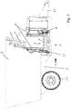
- This unloading device 4 comprises a conveyor 5 5 'conveyor belt arranged transversely to the feed direction A of the mixer 1 and extending at least under the unloading opening 3 over the entire width of the latter.
- the conveyor 5 is movable transversely to the direction of advance A and consists of two parts 6 and 7, in the direction of its longitudinal extension, namely a first part 6 of larger length and a second portion 7 of shorter length, the latter being connected to the first portion 6 by a pivot connection 8 and being movable between several positions inclined with respect to said first portion 6.
- the mixer 1 comprises means which ensure the animation of the working members, for example one or more rotating shafts, advantageously driven by the power take-off of the tractor (not shown) to which it is attached in the variant shown.
- these animation or actuation means may consist of hydraulic or electric motors, powered by a source on board the machine 1 or present on the tractor.
- the tank 2, of substantially cylindrical shape (for example, rectangular section, elliptical or circular), is generally equipped with a vertical rotating shaft 2 'resulting knives 2 "for deagglomerate and mix the various products loaded in the tank 2, then to promote their evacuation through the unloading opening 3.
- the latter which may for example be closed by a shutter or a sliding door 3 ', possibly moved (s) by an actuator 3 ", is typically at level of the lower base of the tank 2, on the front or rear side of the latter and being centered with respect to the longitudinal axis of the mixer 1 (parallel to the direction of advance A).
- This opening 3 generally has a large width (for example up to half the width of the vessel 2) and a substantially rectangular shape.
- the unloading opening may be disposed off-center with respect to the feed direction A and to the median longitudinal axis of the machine 1 and the tank 2.
- the unloading opening may be disposed off-center with respect to the feed direction A and to the median longitudinal axis of the machine 1 and the tank 2.
- the conveyor 5 is advantageously mounted on transverse slides allowing its displacement in translation perpendicular to the longitudinal axis of the mixer 1.
- containment walls 5 for example sheet metal, plastic or canvas
- the pivot connection 8 and the arrangement between the two constituent parts 6 and 7 are configured in such a way that, in its low pivoting position, the second part 7 is coplanar with the first part 6 and the machine 1 comprises first means 9, 14 of pivotal displacement of the second portion 7 and second means 10 of displacement in transverse sliding of the conveyor 5, the first and second means 9, 14; 10 being mutually distinct.
- the invention makes it possible to provide a mixer 1 with a compact unloading device, relatively simple structure, flexible in terms of use and adapted to the needs of users.
- Each of the two types of actuating means 9, 14; 10 may have its own active member or actuator.
- the same member or actuator performs both movements (in translation of the conveyor 5 / pivoting of the second part 7), directly and separately or indirectly and linked, for example by a kinematic mechanism of motion transmission.
- the means 9, 14 for pivotally displacing the second part 7 are controlled independently of the transverse sliding displacement means 10 of the conveyor 5.
- the means 9, 14 for pivotally displacing the second part 7 in a continuous manner and the means 10 for moving the conveyor 5 in a sliding manner are controlled in a manner that is at least partially interdependent, in particular with a conditional or subordinate control of the means 9, 14 of pivotal displacement.
- the second part 7 can take any inclined position, between the horizontal position and its maximum upward inclination position.
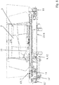
- the total length L of the conveyor 5 is less than the width 1 of the mixing tank 2, in particular less than the largest transverse dimension of the said tank 2. It is therefore not the unloading device 4 which determines the minimum passage width required for the mixer 1.
- the length L1 of the first longitudinal portion 6 of the conveyor 5 is at least equal, preferably at least slightly greater, than the width L0 of the unloading opening 3 of the vessel 2.
- the length L2 of the second longitudinal portion 7 of the conveyor 5 is smaller than the width L0 of the unloading opening 3 of the vessel 2.
- the second longitudinal portion 7 extends at least partially under the unloading opening 3 in its rectilinear configuration (that is to say not inclined with respect to the first part 6, or horizontal) and without offset.
- the total length L of the conveyor 5 is greater than the distance D between each of the lateral edges of the unloading opening. 3 and the opposite lateral side of the tank 2.
- the inclined configuration of the second longitudinal portion 7 can be reached only after an offset of the conveyor 5 at least sufficient so that the axis AP of the pivot connection 8 is outside the bulk of the tank 2.
- the conveyor 5 advantageously comprises three rollers 11, 11 ', 12 for the support and the guided circulation of its conveyor belt 5 ', namely two end rollers 11 and 11', of which at least one is driven or motorized, and an intermediate roller 12, tensioner and return, located at the pivot connection 8 and in pressing under pressure on the lower return portion of said conveyor belt 5 '.
- the conveyor belt 5 ' can flow in both directions by being driven by one of the end rollers 11, 11' so as to discharge the mixed product, in the horizontal straight configuration of the conveyor 5, on the right side or the left side of the mixer 1 (see figure 3 or 4 ).
- the conveyor 5 is also configured to be offset laterally from one or the other side of the mixer 1. More specifically in the case of the mixer 1 shown, the mixed product can be distributed on the right side in rectilinear configuration with offset when the end 14 'of the link 14 is in abutment at the end of the slide 9 under the action of the means 10 which will translate the conveyor 5 to the right.
- the means 10 can move the conveyor 5 to the left in rectilinear configuration. The maximum position of offset to the left is limited by the conveyor 5 itself since its lateral position with respect to the unloading opening 3 must be such that it can recover all of the product poured through the unloading opening 3 in this position.
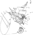
- the mixer 1 is able to dispense the mixed product in raised troughs only on the right side (seen in the direction of advance A) thanks to the conveyor 5 which goes off to the right and the second part 7 which pivots upwards by relative to the pivot connection 8.
- the conveyor 5 may comprise a support frame on which the rollers 11, 11 ', 12 for supporting and guiding the conveyor belt 5' and which is divided into two parts 13 and 13 ', for example U-shaped each, respectively defining the first and second longitudinal parts 6 and 7 of the conveyor 5 and hinged together by the pivot connection 8, the latter connecting for example the ends ends of the branches look at the U-shaped parts between them.
- This support frame is itself slidably mounted on the frame of the mixer 1.
- the axis of rotation AR of the tensioner and return roller 12 is preferably located below the axis AP of the pivot connection 8.
- the axis of rotation AR is preferably shifted below and on the side of the second longitudinal portion 7.
- the pivoting movement means 9, 14 of the second part 7 are controlled in a dependent manner by means of transverse sliding movement of the conveyor 5. It should be noted that the transverse sliding of the conveyor 5 is in this construction, necessary for the axis AR of the tensioning roller 12 and the axis AP of the pivot connection 8 to come out from under the vessel 2 so as to be able to incline the second longitudinal part 7.
- the transverse displacement of the conveyor 5 can be achieved for example by sliding the support frame 13, 13 'on rails or in slides of a support frame mounted transversely on the drawbar of the mixer 1, under the action of a cylinder.
- the rotational displacement of the second part 7, that is to say more precisely of the corresponding support frame part 13 ', around the pivot connection 8 can be realized in different ways, in particular according to other variants than the one represented.
- a rotary actuator can be provided at the pivot connection 8 itself (motorized connection).
- the unloading device 4 may comprise, on each lateral side of the second longitudinal portion 7 of the conveyor 5, a rod 14, pivotally attached by a first end on said second portion 7, these two rods being of variable length by operation and / or having second ends movable in translation in a direction parallel to the longitudinal axis AL of the conveyor 5.
- the second ends 14 'of the rods 14 are slidably mounted on rails or in rails extending under the lateral sides of the second longitudinal part 7 of the conveyor 5, and parallel to these sides, for example by means of pads.
- the second ends 14 'of the rods 14 are hingedly attached at the free ends of sliding portions of telescopic rails 9 extending under the lateral sides of the second longitudinal portion 7 and parallel to its sides, said rail portions 9 being movable in translation by suitable actuators.
- the rods 14 may each represent a telescopic structure for adjusting, possibly by discrete values, the distance between the two ends of the rod 14 considered, that is to say its length LB.
- the second tilting part 7 can be located, seen in the direction of advance A, on the right side (variant shown) or on the left side (variant not shown) of the first part 6 not inclinable and movable in translation transversely to the direction of A.
- the length L1 is approximately double the length L2 (1/3 - 2/3 segmentation of the conveyor 5).
Landscapes
- Life Sciences & Earth Sciences (AREA)
- Environmental Sciences (AREA)
- Birds (AREA)
- Animal Husbandry (AREA)
- Biodiversity & Conservation Biology (AREA)
- Apparatuses For Bulk Treatment Of Fruits And Vegetables And Apparatuses For Preparing Feeds (AREA)
- Accessories For Mixers (AREA)
- Mixers Of The Rotary Stirring Type (AREA)
- Structure Of Belt Conveyors (AREA)
Applications Claiming Priority (1)
| Application Number | Priority Date | Filing Date | Title |
|---|---|---|---|
| FR1750089A FR3061409B1 (fr) | 2017-01-05 | 2017-01-05 | Melangeuse avec un dispositif de dechargement lateral |
Publications (2)
| Publication Number | Publication Date |
|---|---|
| EP3345475A1 true EP3345475A1 (de) | 2018-07-11 |
| EP3345475B1 EP3345475B1 (de) | 2023-10-11 |
Family
ID=58162930
Family Applications (1)
| Application Number | Title | Priority Date | Filing Date |
|---|---|---|---|
| EP18305003.8A Active EP3345475B1 (de) | 2017-01-05 | 2018-01-04 | Mischbehälter mit seitenentladevorrichtung |
Country Status (4)
| Country | Link |
|---|---|
| EP (1) | EP3345475B1 (de) |
| DK (1) | DK3345475T3 (de) |
| ES (1) | ES2967795T3 (de) |
| FR (1) | FR3061409B1 (de) |
Cited By (2)
| Publication number | Priority date | Publication date | Assignee | Title |
|---|---|---|---|---|
| EP4005374A1 (de) | 2020-11-30 | 2022-06-01 | Kuhn-Audureau SAS | Mischer mit einer zweiteiligen auslassöffnung |
| EP4005375A1 (de) | 2020-11-30 | 2022-06-01 | Kuhn-Audureau SAS | Landwirtschaftliches gerät zur verteilung eines produkts, wie z. b. ein mischer, bestehend aus einem behälter mit mindestens einer auslassöffnung |
Citations (3)
| Publication number | Priority date | Publication date | Assignee | Title |
|---|---|---|---|---|
| EP1084612A1 (de) * | 1999-09-13 | 2001-03-21 | Giuseppe Loppoli | Häckselmischwagen mit senkrechter Drehachse für Futter und Grasslage mit adjustierbaren Entladungsmitteln |
| US20080105520A1 (en) * | 2006-10-11 | 2008-05-08 | Kuhn Knight Inc. | Conveyor system with automatic incline |
| EP2189058A2 (de) * | 2008-11-20 | 2010-05-26 | B. Strautmann & Söhne GmbH & Co. KG | Quer zur Fahrtrichtung verschiebbare Entladevorrichtung eines Futtermischwagens sowie ein Förderband zum Ausbringen und Verteilen von Viehfutter |
-
2017
- 2017-01-05 FR FR1750089A patent/FR3061409B1/fr active Active
-
2018
- 2018-01-04 EP EP18305003.8A patent/EP3345475B1/de active Active
- 2018-01-04 DK DK18305003.8T patent/DK3345475T3/da active
- 2018-01-04 ES ES18305003T patent/ES2967795T3/es active Active
Patent Citations (3)
| Publication number | Priority date | Publication date | Assignee | Title |
|---|---|---|---|---|
| EP1084612A1 (de) * | 1999-09-13 | 2001-03-21 | Giuseppe Loppoli | Häckselmischwagen mit senkrechter Drehachse für Futter und Grasslage mit adjustierbaren Entladungsmitteln |
| US20080105520A1 (en) * | 2006-10-11 | 2008-05-08 | Kuhn Knight Inc. | Conveyor system with automatic incline |
| EP2189058A2 (de) * | 2008-11-20 | 2010-05-26 | B. Strautmann & Söhne GmbH & Co. KG | Quer zur Fahrtrichtung verschiebbare Entladevorrichtung eines Futtermischwagens sowie ein Förderband zum Ausbringen und Verteilen von Viehfutter |
Cited By (4)
| Publication number | Priority date | Publication date | Assignee | Title |
|---|---|---|---|---|
| EP4005374A1 (de) | 2020-11-30 | 2022-06-01 | Kuhn-Audureau SAS | Mischer mit einer zweiteiligen auslassöffnung |
| EP4005375A1 (de) | 2020-11-30 | 2022-06-01 | Kuhn-Audureau SAS | Landwirtschaftliches gerät zur verteilung eines produkts, wie z. b. ein mischer, bestehend aus einem behälter mit mindestens einer auslassöffnung |
| FR3116693A1 (fr) | 2020-11-30 | 2022-06-03 | Kuhn-Audureau S.A.S. | Mélangeuse avec un dispositif de déchargement en deux parties |
| FR3116694A1 (fr) | 2020-11-30 | 2022-06-03 | Kuhn-Audureau S.A.S. | Equipement agricole de distribution de produit, telle qu’une mélangeuse, comprenant une cuve avec au moins une ouverture de déchargement |
Also Published As
| Publication number | Publication date |
|---|---|
| EP3345475B1 (de) | 2023-10-11 |
| FR3061409A1 (fr) | 2018-07-06 |
| DK3345475T3 (da) | 2024-01-15 |
| FR3061409B1 (fr) | 2019-05-24 |
| ES2967795T3 (es) | 2024-05-03 |
Similar Documents
| Publication | Publication Date | Title |
|---|---|---|
| EP3345475B1 (de) | Mischbehälter mit seitenentladevorrichtung | |
| EP1250834A1 (de) | Heuwerbungsmaschine mit Schwadgruppierugsvorrichtung | |
| EP3054760B1 (de) | Heuerntemaschine mit verbesserter bodenanpassung | |
| EP0166653B1 (de) | Silageentnehmer, Mischer und Verteiler | |
| EP4005374B1 (de) | Mischer mit einer zweiteiligen auslassöffnung | |
| EP1806048B1 (de) | Landwirtschaftliche Maschine zur Verteilung von Viehfutter mit Bodenfördervorrichtung | |
| EP0659333B1 (de) | Landwirtschaftliche Maschine zur Verteilung von Viehfutter und/oder zum Stroheinstreu | |
| EP3469885A1 (de) | Zylindrische rolle mit zwei teilen mit klinge und landwirtschaftliche maschine mit eine solche rolle | |
| BE1017306A3 (fr) | Godet de chargement et de dechargement. | |
| EP3771333B1 (de) | Maschine zum mischen von einem oder mehreren produkten, insbesondere einem oder mehreren produkten, die der ernährung von tieren dienen, sowie verteilung dieser mischung aus einem oder mehreren solchen produkten | |
| EP3550957B1 (de) | Siloentladerschaufel mit einer vorrichtung zum trennen und entladen von material | |
| EP1405557B1 (de) | Verteilmaschine | |
| EP3297428B1 (de) | Schaufel zur aufnahme und zur verteilung, versehen mit verbesserten auflockermitteln | |
| EP0081447B1 (de) | Maschinen zur Entnahme von Futterblocks aus einem Silo | |
| FR2770369A1 (fr) | Machine agricole telle que pailleuse ou pailleuse-desileuse | |
| FR2769793A1 (fr) | Machine agricole de deroulage de balles rondes | |
| FR2754671A1 (fr) | Dispositif pour prelever et charger des produits ensiles | |
| FR2920635A1 (fr) | Dispositif d'epandage, notamment de fumier | |
| FR2768014A1 (fr) | Epandeur a deux disques a cadre de protection | |
| FR2768415A1 (fr) | Dispositif de convoyage et d'elevation d'articles pour le chargement d'un vehicule | |
| FR2771896A1 (fr) | Dispositif pour distribuer la matiere vegetale d'une balle cylindrique | |
| FR3032662A1 (fr) | Benne comprenant un module de distribution amovible et module de distribution associe | |
| FR2759537A1 (fr) | Machine agricole de deroulage de balles rondes | |
| FR2770370A1 (fr) | Desileuse distributrice pour des produits agricoles tels que du fourrage ou les produits emballes dans une balle enrubannee tres compacte | |
| FR3032696A1 (fr) | Module de distribution d'une benne et benne equipee d'un tel module |
Legal Events
| Date | Code | Title | Description |
|---|---|---|---|
| PUAI | Public reference made under article 153(3) epc to a published international application that has entered the european phase |
Free format text: ORIGINAL CODE: 0009012 |
|
| STAA | Information on the status of an ep patent application or granted ep patent |
Free format text: STATUS: THE APPLICATION HAS BEEN PUBLISHED |
|
| AK | Designated contracting states |
Kind code of ref document: A1 Designated state(s): AL AT BE BG CH CY CZ DE DK EE ES FI FR GB GR HR HU IE IS IT LI LT LU LV MC MK MT NL NO PL PT RO RS SE SI SK SM TR |
|
| AX | Request for extension of the european patent |
Extension state: BA ME |
|
| STAA | Information on the status of an ep patent application or granted ep patent |
Free format text: STATUS: REQUEST FOR EXAMINATION WAS MADE |
|
| 17P | Request for examination filed |
Effective date: 20190109 |
|
| RBV | Designated contracting states (corrected) |
Designated state(s): AL AT BE BG CH CY CZ DE DK EE ES FI FR GB GR HR HU IE IS IT LI LT LU LV MC MK MT NL NO PL PT RO RS SE SI SK SM TR |
|
| STAA | Information on the status of an ep patent application or granted ep patent |
Free format text: STATUS: EXAMINATION IS IN PROGRESS |
|
| 17Q | First examination report despatched |
Effective date: 20190403 |
|
| RIN1 | Information on inventor provided before grant (corrected) |
Inventor name: SORIN, BENOIT Inventor name: MIGNON, FLORENT |
|
| RAP1 | Party data changed (applicant data changed or rights of an application transferred) |
Owner name: KUHN-AUDUREAU SAS |
|
| STAA | Information on the status of an ep patent application or granted ep patent |
Free format text: STATUS: EXAMINATION IS IN PROGRESS |
|
| STAA | Information on the status of an ep patent application or granted ep patent |
Free format text: STATUS: EXAMINATION IS IN PROGRESS |
|
| GRAP | Despatch of communication of intention to grant a patent |
Free format text: ORIGINAL CODE: EPIDOSNIGR1 |
|
| STAA | Information on the status of an ep patent application or granted ep patent |
Free format text: STATUS: GRANT OF PATENT IS INTENDED |
|
| INTG | Intention to grant announced |
Effective date: 20230509 |
|
| P01 | Opt-out of the competence of the unified patent court (upc) registered |
Effective date: 20230622 |
|
| GRAS | Grant fee paid |
Free format text: ORIGINAL CODE: EPIDOSNIGR3 |
|
| GRAA | (expected) grant |
Free format text: ORIGINAL CODE: 0009210 |
|
| STAA | Information on the status of an ep patent application or granted ep patent |
Free format text: STATUS: THE PATENT HAS BEEN GRANTED |
|
| AK | Designated contracting states |
Kind code of ref document: B1 Designated state(s): AL AT BE BG CH CY CZ DE DK EE ES FI FR GB GR HR HU IE IS IT LI LT LU LV MC MK MT NL NO PL PT RO RS SE SI SK SM TR |
|
| REG | Reference to a national code |
Ref country code: GB Ref legal event code: FG4D Free format text: NOT ENGLISH |
|
| REG | Reference to a national code |
Ref country code: CH Ref legal event code: EP |
|
| REG | Reference to a national code |
Ref country code: DE Ref legal event code: R096 Ref document number: 602018059093 Country of ref document: DE |
|
| REG | Reference to a national code |
Ref country code: IE Ref legal event code: FG4D Free format text: LANGUAGE OF EP DOCUMENT: FRENCH |
|
| REG | Reference to a national code |
Ref country code: DK Ref legal event code: T3 Effective date: 20240110 |
|
| REG | Reference to a national code |
Ref country code: NL Ref legal event code: FP |
|
| REG | Reference to a national code |
Ref country code: LT Ref legal event code: MG9D |
|
| PGFP | Annual fee paid to national office [announced via postgrant information from national office to epo] |
Ref country code: NL Payment date: 20240126 Year of fee payment: 7 |
|
| REG | Reference to a national code |
Ref country code: AT Ref legal event code: MK05 Ref document number: 1619263 Country of ref document: AT Kind code of ref document: T Effective date: 20231011 |
|
| PG25 | Lapsed in a contracting state [announced via postgrant information from national office to epo] |
Ref country code: GR Free format text: LAPSE BECAUSE OF FAILURE TO SUBMIT A TRANSLATION OF THE DESCRIPTION OR TO PAY THE FEE WITHIN THE PRESCRIBED TIME-LIMIT Effective date: 20240112 |
|
| PG25 | Lapsed in a contracting state [announced via postgrant information from national office to epo] |
Ref country code: IS Free format text: LAPSE BECAUSE OF FAILURE TO SUBMIT A TRANSLATION OF THE DESCRIPTION OR TO PAY THE FEE WITHIN THE PRESCRIBED TIME-LIMIT Effective date: 20240211 |
|
| PG25 | Lapsed in a contracting state [announced via postgrant information from national office to epo] |
Ref country code: LT Free format text: LAPSE BECAUSE OF FAILURE TO SUBMIT A TRANSLATION OF THE DESCRIPTION OR TO PAY THE FEE WITHIN THE PRESCRIBED TIME-LIMIT Effective date: 20231011 |
|
| PGFP | Annual fee paid to national office [announced via postgrant information from national office to epo] |
Ref country code: IE Payment date: 20240129 Year of fee payment: 7 Ref country code: ES Payment date: 20240201 Year of fee payment: 7 |
|
| PG25 | Lapsed in a contracting state [announced via postgrant information from national office to epo] |
Ref country code: AT Free format text: LAPSE BECAUSE OF FAILURE TO SUBMIT A TRANSLATION OF THE DESCRIPTION OR TO PAY THE FEE WITHIN THE PRESCRIBED TIME-LIMIT Effective date: 20231011 |
|
| PG25 | Lapsed in a contracting state [announced via postgrant information from national office to epo] |
Ref country code: LT Free format text: LAPSE BECAUSE OF FAILURE TO SUBMIT A TRANSLATION OF THE DESCRIPTION OR TO PAY THE FEE WITHIN THE PRESCRIBED TIME-LIMIT Effective date: 20231011 Ref country code: IS Free format text: LAPSE BECAUSE OF FAILURE TO SUBMIT A TRANSLATION OF THE DESCRIPTION OR TO PAY THE FEE WITHIN THE PRESCRIBED TIME-LIMIT Effective date: 20240211 Ref country code: GR Free format text: LAPSE BECAUSE OF FAILURE TO SUBMIT A TRANSLATION OF THE DESCRIPTION OR TO PAY THE FEE WITHIN THE PRESCRIBED TIME-LIMIT Effective date: 20240112 Ref country code: BG Free format text: LAPSE BECAUSE OF FAILURE TO SUBMIT A TRANSLATION OF THE DESCRIPTION OR TO PAY THE FEE WITHIN THE PRESCRIBED TIME-LIMIT Effective date: 20240111 Ref country code: AT Free format text: LAPSE BECAUSE OF FAILURE TO SUBMIT A TRANSLATION OF THE DESCRIPTION OR TO PAY THE FEE WITHIN THE PRESCRIBED TIME-LIMIT Effective date: 20231011 Ref country code: PT Free format text: LAPSE BECAUSE OF FAILURE TO SUBMIT A TRANSLATION OF THE DESCRIPTION OR TO PAY THE FEE WITHIN THE PRESCRIBED TIME-LIMIT Effective date: 20240212 |
|
| PGFP | Annual fee paid to national office [announced via postgrant information from national office to epo] |
Ref country code: DE Payment date: 20240129 Year of fee payment: 7 Ref country code: GB Payment date: 20240129 Year of fee payment: 7 |
|
| REG | Reference to a national code |
Ref country code: ES Ref legal event code: FG2A Ref document number: 2967795 Country of ref document: ES Kind code of ref document: T3 Effective date: 20240503 |
|
| PG25 | Lapsed in a contracting state [announced via postgrant information from national office to epo] |
Ref country code: SE Free format text: LAPSE BECAUSE OF FAILURE TO SUBMIT A TRANSLATION OF THE DESCRIPTION OR TO PAY THE FEE WITHIN THE PRESCRIBED TIME-LIMIT Effective date: 20231011 Ref country code: RS Free format text: LAPSE BECAUSE OF FAILURE TO SUBMIT A TRANSLATION OF THE DESCRIPTION OR TO PAY THE FEE WITHIN THE PRESCRIBED TIME-LIMIT Effective date: 20231011 Ref country code: PL Free format text: LAPSE BECAUSE OF FAILURE TO SUBMIT A TRANSLATION OF THE DESCRIPTION OR TO PAY THE FEE WITHIN THE PRESCRIBED TIME-LIMIT Effective date: 20231011 Ref country code: NO Free format text: LAPSE BECAUSE OF FAILURE TO SUBMIT A TRANSLATION OF THE DESCRIPTION OR TO PAY THE FEE WITHIN THE PRESCRIBED TIME-LIMIT Effective date: 20240111 Ref country code: LV Free format text: LAPSE BECAUSE OF FAILURE TO SUBMIT A TRANSLATION OF THE DESCRIPTION OR TO PAY THE FEE WITHIN THE PRESCRIBED TIME-LIMIT Effective date: 20231011 Ref country code: HR Free format text: LAPSE BECAUSE OF FAILURE TO SUBMIT A TRANSLATION OF THE DESCRIPTION OR TO PAY THE FEE WITHIN THE PRESCRIBED TIME-LIMIT Effective date: 20231011 |
|
| PGFP | Annual fee paid to national office [announced via postgrant information from national office to epo] |
Ref country code: IT Payment date: 20240122 Year of fee payment: 7 Ref country code: FR Payment date: 20240125 Year of fee payment: 7 Ref country code: DK Payment date: 20240125 Year of fee payment: 7 Ref country code: BE Payment date: 20240129 Year of fee payment: 7 |
|
| REG | Reference to a national code |
Ref country code: DE Ref legal event code: R097 Ref document number: 602018059093 Country of ref document: DE |
|
| PG25 | Lapsed in a contracting state [announced via postgrant information from national office to epo] |
Ref country code: CZ Free format text: LAPSE BECAUSE OF FAILURE TO SUBMIT A TRANSLATION OF THE DESCRIPTION OR TO PAY THE FEE WITHIN THE PRESCRIBED TIME-LIMIT Effective date: 20231011 |
|
| PG25 | Lapsed in a contracting state [announced via postgrant information from national office to epo] |
Ref country code: SK Free format text: LAPSE BECAUSE OF FAILURE TO SUBMIT A TRANSLATION OF THE DESCRIPTION OR TO PAY THE FEE WITHIN THE PRESCRIBED TIME-LIMIT Effective date: 20231011 |
|
| PG25 | Lapsed in a contracting state [announced via postgrant information from national office to epo] |
Ref country code: SM Free format text: LAPSE BECAUSE OF FAILURE TO SUBMIT A TRANSLATION OF THE DESCRIPTION OR TO PAY THE FEE WITHIN THE PRESCRIBED TIME-LIMIT Effective date: 20231011 Ref country code: SK Free format text: LAPSE BECAUSE OF FAILURE TO SUBMIT A TRANSLATION OF THE DESCRIPTION OR TO PAY THE FEE WITHIN THE PRESCRIBED TIME-LIMIT Effective date: 20231011 Ref country code: RO Free format text: LAPSE BECAUSE OF FAILURE TO SUBMIT A TRANSLATION OF THE DESCRIPTION OR TO PAY THE FEE WITHIN THE PRESCRIBED TIME-LIMIT Effective date: 20231011 Ref country code: EE Free format text: LAPSE BECAUSE OF FAILURE TO SUBMIT A TRANSLATION OF THE DESCRIPTION OR TO PAY THE FEE WITHIN THE PRESCRIBED TIME-LIMIT Effective date: 20231011 Ref country code: CZ Free format text: LAPSE BECAUSE OF FAILURE TO SUBMIT A TRANSLATION OF THE DESCRIPTION OR TO PAY THE FEE WITHIN THE PRESCRIBED TIME-LIMIT Effective date: 20231011 |
|
| PLBE | No opposition filed within time limit |
Free format text: ORIGINAL CODE: 0009261 |
|
| STAA | Information on the status of an ep patent application or granted ep patent |
Free format text: STATUS: NO OPPOSITION FILED WITHIN TIME LIMIT |
|
| PG25 | Lapsed in a contracting state [announced via postgrant information from national office to epo] |
Ref country code: MC Free format text: LAPSE BECAUSE OF FAILURE TO SUBMIT A TRANSLATION OF THE DESCRIPTION OR TO PAY THE FEE WITHIN THE PRESCRIBED TIME-LIMIT Effective date: 20231011 |
|
| PG25 | Lapsed in a contracting state [announced via postgrant information from national office to epo] |
Ref country code: MC Free format text: LAPSE BECAUSE OF FAILURE TO SUBMIT A TRANSLATION OF THE DESCRIPTION OR TO PAY THE FEE WITHIN THE PRESCRIBED TIME-LIMIT Effective date: 20231011 |
|
| REG | Reference to a national code |
Ref country code: CH Ref legal event code: PL |
|
| PG25 | Lapsed in a contracting state [announced via postgrant information from national office to epo] |
Ref country code: LU Free format text: LAPSE BECAUSE OF NON-PAYMENT OF DUE FEES Effective date: 20240104 |
|
| 26N | No opposition filed |
Effective date: 20240712 |