EP3345468B1 - Measuring and/or checking system including at least two units, and method to connect such units - Google Patents
Measuring and/or checking system including at least two units, and method to connect such units Download PDFInfo
- Publication number
- EP3345468B1 EP3345468B1 EP16760045.1A EP16760045A EP3345468B1 EP 3345468 B1 EP3345468 B1 EP 3345468B1 EP 16760045 A EP16760045 A EP 16760045A EP 3345468 B1 EP3345468 B1 EP 3345468B1
- Authority
- EP
- European Patent Office
- Prior art keywords
- unit
- multipolar
- cable
- connector
- master unit
- Prior art date
- Legal status (The legal status is an assumption and is not a legal conclusion. Google has not performed a legal analysis and makes no representation as to the accuracy of the status listed.)
- Active
Links
Images


Classifications
-
- H—ELECTRICITY
- H01—ELECTRIC ELEMENTS
- H01R—ELECTRICALLY-CONDUCTIVE CONNECTIONS; STRUCTURAL ASSOCIATIONS OF A PLURALITY OF MUTUALLY-INSULATED ELECTRICAL CONNECTING ELEMENTS; COUPLING DEVICES; CURRENT COLLECTORS
- H01R13/00—Details of coupling devices of the kinds covered by groups H01R12/70 or H01R24/00 - H01R33/00
- H01R13/46—Bases; Cases
- H01R13/502—Bases; Cases composed of different pieces
-
- H—ELECTRICITY
- H01—ELECTRIC ELEMENTS
- H01R—ELECTRICALLY-CONDUCTIVE CONNECTIONS; STRUCTURAL ASSOCIATIONS OF A PLURALITY OF MUTUALLY-INSULATED ELECTRICAL CONNECTING ELEMENTS; COUPLING DEVICES; CURRENT COLLECTORS
- H01R13/00—Details of coupling devices of the kinds covered by groups H01R12/70 or H01R24/00 - H01R33/00
- H01R13/46—Bases; Cases
- H01R13/516—Means for holding or embracing insulating body, e.g. casing, hoods
-
- H—ELECTRICITY
- H01—ELECTRIC ELEMENTS
- H01R—ELECTRICALLY-CONDUCTIVE CONNECTIONS; STRUCTURAL ASSOCIATIONS OF A PLURALITY OF MUTUALLY-INSULATED ELECTRICAL CONNECTING ELEMENTS; COUPLING DEVICES; CURRENT COLLECTORS
- H01R13/00—Details of coupling devices of the kinds covered by groups H01R12/70 or H01R24/00 - H01R33/00
- H01R13/66—Structural association with built-in electrical component
- H01R13/665—Structural association with built-in electrical component with built-in electronic circuit
- H01R13/6691—Structural association with built-in electrical component with built-in electronic circuit with built-in signalling means
-
- H—ELECTRICITY
- H01—ELECTRIC ELEMENTS
- H01R—ELECTRICALLY-CONDUCTIVE CONNECTIONS; STRUCTURAL ASSOCIATIONS OF A PLURALITY OF MUTUALLY-INSULATED ELECTRICAL CONNECTING ELEMENTS; COUPLING DEVICES; CURRENT COLLECTORS
- H01R4/00—Electrically-conductive connections between two or more conductive members in direct contact, i.e. touching one another; Means for effecting or maintaining such contact; Electrically-conductive connections having two or more spaced connecting locations for conductors and using contact members penetrating insulation
- H01R4/24—Connections using contact members penetrating or cutting insulation or cable strands
- H01R4/2416—Connections using contact members penetrating or cutting insulation or cable strands the contact members having insulation-cutting edges, e.g. of tuning fork type
- H01R4/242—Connections using contact members penetrating or cutting insulation or cable strands the contact members having insulation-cutting edges, e.g. of tuning fork type the contact members being plates having a single slot
- H01R4/2425—Flat plates, e.g. multi-layered flat plates
- H01R4/2429—Flat plates, e.g. multi-layered flat plates mounted in an insulating base
- H01R4/2433—Flat plates, e.g. multi-layered flat plates mounted in an insulating base one part of the base being movable to push the cable into the slot
-
- H—ELECTRICITY
- H01—ELECTRIC ELEMENTS
- H01R—ELECTRICALLY-CONDUCTIVE CONNECTIONS; STRUCTURAL ASSOCIATIONS OF A PLURALITY OF MUTUALLY-INSULATED ELECTRICAL CONNECTING ELEMENTS; COUPLING DEVICES; CURRENT COLLECTORS
- H01R43/00—Apparatus or processes specially adapted for manufacturing, assembling, maintaining, or repairing of line connectors or current collectors or for joining electric conductors
- H01R43/01—Apparatus or processes specially adapted for manufacturing, assembling, maintaining, or repairing of line connectors or current collectors or for joining electric conductors for connecting unstripped conductors to contact members having insulation cutting edges
-
- H—ELECTRICITY
- H01—ELECTRIC ELEMENTS
- H01R—ELECTRICALLY-CONDUCTIVE CONNECTIONS; STRUCTURAL ASSOCIATIONS OF A PLURALITY OF MUTUALLY-INSULATED ELECTRICAL CONNECTING ELEMENTS; COUPLING DEVICES; CURRENT COLLECTORS
- H01R43/00—Apparatus or processes specially adapted for manufacturing, assembling, maintaining, or repairing of line connectors or current collectors or for joining electric conductors
- H01R43/26—Apparatus or processes specially adapted for manufacturing, assembling, maintaining, or repairing of line connectors or current collectors or for joining electric conductors for engaging or disengaging the two parts of a coupling device
-
- H—ELECTRICITY
- H05—ELECTRIC TECHNIQUES NOT OTHERWISE PROVIDED FOR
- H05K—PRINTED CIRCUITS; CASINGS OR CONSTRUCTIONAL DETAILS OF ELECTRIC APPARATUS; MANUFACTURE OF ASSEMBLAGES OF ELECTRICAL COMPONENTS
- H05K7/00—Constructional details common to different types of electric apparatus
- H05K7/14—Mounting supporting structure in casing or on frame or rack
- H05K7/1462—Mounting supporting structure in casing or on frame or rack for programmable logic controllers [PLC] for automation or industrial process control
- H05K7/1468—Mechanical features of input/output (I/O) modules
- H05K7/1469—Terminal blocks for connecting sensors
-
- H—ELECTRICITY
- H05—ELECTRIC TECHNIQUES NOT OTHERWISE PROVIDED FOR
- H05K—PRINTED CIRCUITS; CASINGS OR CONSTRUCTIONAL DETAILS OF ELECTRIC APPARATUS; MANUFACTURE OF ASSEMBLAGES OF ELECTRICAL COMPONENTS
- H05K7/00—Constructional details common to different types of electric apparatus
- H05K7/14—Mounting supporting structure in casing or on frame or rack
- H05K7/1462—Mounting supporting structure in casing or on frame or rack for programmable logic controllers [PLC] for automation or industrial process control
- H05K7/1468—Mechanical features of input/output (I/O) modules
- H05K7/1472—Bus coupling modules, e.g. bus distribution modules
Definitions
- the present invention relates to a measuring and/or checking system, including at least two units, each comprising electronic circuits, and a multipolar cable with multipolar connectors, and a method for connecting the two units.
- the system and method are used advantageously in the checking operations performed by a machine tool.
- German patent application published with n. DE4207402A1 shows devices connecting electronic units, including plug adapters with particular arrangements and operation of electric contacts.
- International patent application published with n. WO2009/119028A1 shows an electric modular system with cable connected units.
- EP0909121A2 refers to an electronic I/O module with an electronic unit, a termination device with input/output terminations and a bus termination element coupled to the termination device via the electronic unit.
- control unit CNC, Computer Numerical Control
- CNC Computer Numerical Control
- the numerical control unit detects in real time measurements of the mechanical piece being processed and machine parameters (for example temperature, imbalance of rotary tools, acoustic emissions) and/or controls actuators located in the machine tool, for example for moving balancing weights or carriages.
- machine parameters for example temperature, imbalance of rotary tools, acoustic emissions
- actuators located in the machine tool, for example for moving balancing weights or carriages.
- devices are present in the machine tool, such as sensors and/or actuators, adapted to exchange operational signals with the control unit.
- the control unit receives data detected by the sensors and/or transmits control signals to the actuators.
- a data processing and transmission system is used, operatively interposed between the control unit and the devices.
- the checking performed by the numerical control unit may be basically of two types with respect to the actions performed by the machine tool to be checked: post-process or in-process, depending on whether the checking takes place, respectively, after the action performed by the machine or during the machining with feedback on the machine.
- the prior art teaches the use of centralized intelligence data processing and transmission systems.
- the processing hardware of the data processing and transmission system is concentrated in a single apparatus, that is positioned in the electrical cabinet and has a plurality of ports for a parallel connection with the various devices by respective cables.
- all the operational signals are connected to the single apparatus, and the synchronisation occurs inside the apparatuses.
- a first drawback is due to the fact that the apparatus is bulky and not very flexible, in the sense that it has predetermined dimensions and number of ports which cannot be adapted to the specific application; this means that the apparatus is generally over-sized for a specific application.
- a further drawback is due to the installation difficulty, due to the high number of cables to be connected to the apparatus.
- the distance between the devices and the processing hardware is the cause of not insignificant noise and has a negative effect on the accuracy of the checking.
- a first drawback is due to the fact that they do not allow an effective and simple synchronisation of the data. Another difficulty of these systems is linked to the correlation of the data acquired by the various devices.
- Another limitation of such systems is linked to the reliability, in terms of continuity of service and the possibility of preventing faults and malfunctions.
- the aim of the present invention is to provide a data processing and transmission system and method for a numeral control unit adapted to control a machine tool which overcome the above-mentioned drawbacks of the prior art.
- an aim of the present invention is to provide a data processing and transmission system and method which are particularly flexible, which can be adapted simply to the different requirements of use.
- Another aim of the present invention is to provide a data processing and transmission system and method which allow a simple and effective in-process checking to be performed.
- Another aim of the invention is to provide a data processing and transmission system and method which are particularly reliable.
- Another aim of the present invention is to provide a data processing and transmission system and method which allow a particularly simple and effective data synchronising.
- the data processing and transmission system is adapted to be connected to at least one device present in the machine tool.
- the device may be a sensor (with relative transducer) or an actuator. More specifically, the data processing and transmission system is adapted to be connected to a plurality of devices such as sensors and/or actuators.
- the system comprises at least one input channel adapted to a transit of operational signals from or to devices present in the machine tool. Moreover, the system includes electronic circuits configured to process the operational signals to make available on an output interface control signals for the numerical control unit.
- the data processing and transmission system is equipped with a multipolar cable having a first and a second end, each provided with a multipolar connector.
- the processing and transmission system has a master unit, equipped with a main processor, a memory and at least one socket configured to be coupled to one of the multipolar connectors; moreover, the master unit comprises the output interface toward the control unit.
- the processing and transmission system also comprises one or more slave units which are connected to the master unit.
- Each slave unit has at least one external port, defining one of the input channels of the system for a connection to a device.
- the slave unit has its own memory and a secondary processor.
- the slave unit is also equipped with a first socket and a second socket, configured to be coupled at least to a first and a second connector of the multipolar connectors. In this way, the slave unit is interconnected with the master unit.
- the multipolar cable makes it possible to connect a plurality of slave units to each other and to the master unit, for example in a daisy chain configuration, in such a way that there is a single multipolar cable in the data processing and transmission system connected to the master unit to exchange data with the slave units.
- the data processing and transmission system makes it possible to create a network including a master unit and one or more slave units, interconnected by means of the multipolar cable.
- the system is particularly flexible, because it may be adapted to interconnect different configurations of devices simply by adding or removing slave units, without having to over-size the master unit.
- the first and/or the second socket may be connected to at least one first or one second socket of a further slave unit either directly or by a piece of the multipolar cable.
- the first and/or the second socket may be connected to at least one first or one second socket of a further slave unit either directly or by a piece of the multipolar cable.
- the multipolar cable defines a plurality of communication channels, which are different from each other according to hierarchical levels depending on the communication speed and complexity (for example, Ethernet, CAN and RS485, in decreasing order of ranking).
- the slave unit always has its own unique address which may be detected by the master unit through the multipolar cable and acts as a repeater of the signals circulating in the multipolar cable.
- the slave units may have different functions (depending on the configuration of one of their printed circuit board), but they have in common the presence of an external port for connection to a device, a memory and a processor adapted to allow a communication through the channel of higher ranking (within the plurality of channels provided by the multipolar cable).
- the system can also comprise at least one ancillary unit, provided with a first socket and a second socket configured to connect to at least one of the first and second sockets of at least one slave unit.
- the ancillary unit is interconnected in the multipolar cable and it propagates the signal.
- the ancillary unit relative to the slave unit, does not have one or more of the above-mentioned features: external port, memory or processor adapted to allow a communication through the channel of higher ranking.
- the ancillary unit differs from the slave unit since it may have one or more of these properties, but not all.
- an ancillary unit might be without the memory and/or the external port and/or a processor; it could have a programmable logic or other processing means allowing access to a communication channel of lower ranking (for example, CAN and RS485); or, it could be totally invisible to the master unit (as it does not have an identification code), in which case it can communicate exclusively with the slave unit to which it is connected.
- At least one operation of the ancillary unit is exclusively related to an operation of the slave unit to which it is connected. In other words, in relation to this operation, the ancillary unit performs only functions necessary for the respective slave unit.
- the master unit is connected to other units, which allow an extension of the functions of the master unit.
- the master unit is equipped with a first and a second socket and the system comprises a dedicated bridge connector.
- the bridge connector has a first and a second end and comprises a first multipolar connector at the first end and a second multipolar connector at the second end. Both the first and the second connector can be coupled (directly) to one of the first or second sockets of the master unit and to a socket of the supplementary unit.
- bridge connector according to the present invention can be used, advantageously, in any data processing and transmission system for numeral control unit adapted to control a machine tool, which comprises a unit adapted to be connectable modularly to another unit positioned alongside (for example with both the units connected mechanically to a DIN rail in an electrical panel or switchboard).
- the connector bridge according to the present invention may be used in measuring and/or control systems comprising at least one first and one second unit positioned side by side and configured to be connected to each other.
- both the first and the second connector of the bridge connector has retractable (spring type) electrical contacts to facilitate the operations of electrical connection to corresponding sockets of respective units of the system, these sockets comprising, for example, planar electrical contacts, or padtime slot s, adapted to cooperate with such retractable contacts.
- the data processing and transmission system comprises a fast wiring multipolar connector, for assembling in-situ, quickly and simply the connector to an end of the multipolar cable.
- the fast wiring multipolar connector is equipped with perforating electrical contacts, configured to perforate an insulating sheath which covers the wires contained in the multipolar cable and fixed to the wires.
- the fast wiring multipolar connector has a first body, equipped with a first group of electrical contacts with a plurality of contact pins which can be coupled to the multipolar socket of the master unit, and a second body, which can be plugged into the first body and equipped with perforating electrical contacts.
- the contact pins of the first body are retractable (or "spring type") electrical contacts.
- the fast wiring multipolar connector according to the present invention can be used, advantageously, in any data processing and transmission system for numeral control unit adapted to control a machine tool, which uses a multipolar cable.
- the advantage of assembling in a quick and easy manner a connector to one of the two ends of the cable is not limited to distributed intelligence systems.
- the other end of the multipolar cable preferably has a pre-assembled multipolar connector, having special sealing capacity with regard to moisture and dust.
- the fast wiring multipolar connector according to the present invention may be advantageously used in measurement and/or checking systems comprising at least one first and one second unit with sockets configured to be coupled to multipolar connectors of a cable, to make the electrical connection.
- the multipolar cable also has the function of electrically powering the slave units.
- the master unit has a clock and each slave unit has its own clock.
- the main processor is programmed to generate a synchronisation signal and to transmit the synchronisation signal through the multipolar cable, in order to synchronise all the clocks of the slave units with the clock of the master unit.
- the synchronization of the clocks is implemented according to the method provided by the IEEE 1588 Precision Time Protocol (PTP).
- PTP Precision Time Protocol
- the master unit sends, through for example the Ethernet communication channel, a synchronization signal that is received almost simultaneously by all the slave units. More specifically, the synchronization signal sent by the master unit is propagated through the slave units, starting from the nearest one in the series, and is received by every slave unit that synchronizes its own clocks independently from the other slave units. Every slave unit receives the synchronization signal with a minimal delay with respect to the upstream slave unit due to the signal propagation time.
- the synchronization signal is transmitted as it is by every slave unit, that is to say, every slave unit receives the synchronization signal as it is generated by the master unit, the signal is not processed by the slave unit before reaching the other one.
- two or more slave units comprise an electronic circuit for generating an alternating electric excitation signal (for an inductive transducer of a sensor to which the slave unit is connected). All the alternating electric excitation signals generated are synchronised temporally with each other. This prevents noise in the system due to a beat phenomenon generated by the simultaneous presence of unsynchronised sinusoidal signals. This noise is typically low frequency and is particularly harmful to the system.
- the main processor is programmed to divide a data transmission time interval into a plurality of time slot sand to uniquely assign to each slave unit a corresponding time-slot of the plurality of time slots.
- the secondary processor can be set for transmitting data through the multipolar cable only within the respective time slot.
- the main processor is programmed to assign to each slave unit a unique identification code and it is programmed to perform a continuous data collection cycle. At each time slot of the data transmission time interval the main processor receives and stores the data transmitted by the corresponding slave unit and associates the data with the slave unit which the data comes from.
- each slave unit is configured to receive at least one operational signal through the external port, and to acquire and store corresponding data.
- each slave unit is configured to assign corresponding acquisition instants to the data acquired, on the basis of its own clock.
- the master unit comprises a diagnostic block.
- the diagnostic block has electronic circuits and is configured for detecting or collecting, at least for the master unit, at least one power supply parameter. Alternatively or in addition, the diagnostic block is configured for collecting, at least for the master unit and/or for one or more of the slave units, an internal temperature.
- the diagnostic block is configured for collecting the internal temperatures of both the master unit and all the slave (and ancillary) units.
- the diagnostic block is configured for collecting at least one power supply parameter also for the slave units, taken individually, or for the entire system, that is, all the slave units and the master unit.
- the diagnostic block of the master unit is configured for detecting or collecting one or more of the following parameters: supply voltage, electrical current draw, power draw.
- the diagnostic block is connected to an electrical power supply of the master unit: to prevent that the detection of the at least one power supply parameter causes an electromagnetic pollution in the electronic components of the system the diagnostic block is coupled to the main processor through an opto-isolated interface.
- the multipolar cable preferably contains one or more wires (at least one supply and one return) which define an electrical power supply for the system, in particular for the slave and ancillary units.
- the slave (and ancillary) units and preferably also the master unit are connected in parallel to the power supply wires.
- the slave (and ancillary) units and preferably also the master unit each have a power supply circuit (for example a DC/DC converter) defining a galvanic insulation, interposed between the relative electronic components (to be powered) and the power supply wires.
- a power supply circuit for example a DC/DC converter
- the purpose of this is to guarantee that the electronic components of the slave (and ancillary) units and the master unit operate in a "clean" electric room.
- the diagnostic block has its own connection with the power supply wires, whilst the interface with the main processor is insulated galvanically, for example by an optical connection (coupling).
- This allows the diagnostic block to read voltage and current or other quantities representing an electricity consumption by the system, without causing alterations in the electrical power supply of the electronic components of the master unit.
- An optical coupling with relative voltage or current reading may be provided in one or more of the ancillary units.
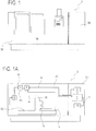
- the reference number 1 indicates a data processing and transmission system for a numerical control unit 2 adapted to control a machine tool 3.
- the machine tool 3 has a work chamber 3A, in which at least one tool is positioned.
- the work chamber 3A defines its own inner space 3C, that is to say a work space.
- the work space 3C constitutes a polluted (dirty) environment.
- the machine tool 3 also comprises, typically, an electrical panel or switchboard 3B, in which the numerical control unit 2 is positioned.
- the electrical panel 3B defines its own inner space 3D.
- the inner space 3D of the electrical panel 3B constitutes a relatively clean environment; indeed, it is separated, for example by a wall, from the work space 3C of the machine tool 3.
- the system 1 comprises at least one input channel 4 adapted to a transit of operational signals from devices 15 present in the machine tool 3 or to devices 15 present in the machine tool 3.
- the system 1 also comprises electronic circuits configured to process the operational signals to make available on an output interface 5 control signals for the numerical control unit 2.
- the devices 15 are positioned in the work space 3C of the machine tool 3 and can be for example sensors or actuators.
- the system 1 comprises one or more slave units 6, that is, at least one slave unit 6, provided with at least one external port 6A, defining the input channel 4.
- the system 1 comprises a master unit 7 having the output interface 5.
- the master unit 7 is located in the space 3D of the electrical panel, and is therefore positioned in the non-polluted environment, close to the numeral control unit 2.
- At least one of the slave units 6 is located in the work space 3C, close to a respective device 15 (thus minimising also the length of the cable, or the cables connecting the slave unit 6 to the respective device 15).
- slave units 6 are preferably located in the work space 3C; however, one or more slave units 6 may be positioned in the space 3D of the electrical panel, depending on the relative function.
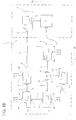
- the master unit 7 comprises a memory (that is, main memory) 7R and a main processor 7S.
- Each slave unit 6 comprises a memory (that is, secondary memory) 6R and a secondary processor 6S.
- the slave unit 6 is configured for acquiring at least one operational signal through the external port 6A and storing it in the memory 6R.
- the system 1 comprises a multipolar cable 8 for connecting at least one of the slave units 6 to the master unit 7.
- the multipolar cable 8 is inserted in an opening in the partition wall which separates the work space 3C from the space 3D of the electrical panel.
- connection between the slave units 6 may be carried out by pieces of multipolar cable 8 or by direct connection of the sockets 6B and 6C.
- the multipolar cable 8 has a first and a second end, each end provided with a multipolar connector 9.
- the master unit 7 comprises at least one first socket 7A configured to be coupled to one of the multipolar connectors 9.
- Each slave units 6 is provided with a first socket 6B and a second socket 6C, configured to be coupled at least to one first or one second connector of the multipolar connectors.
- the multipolar cable 8 connects the at least one slave unit 6 to the master unit 7.
- the system 1 comprises a plurality of slave units 6 connected in series to each other and one of them is connected to the master unit 7 by means of a piece of the multipolar cable 8.
- the slave units are connected to each other directly or by the multipolar cable 8.
- the system 1 comprises at least two slave units 6, that is to say, it comprises a plurality of slave units 6.
- the system 1 comprises a multipolar connector 16.
- the multiple connector 16 has a first, a second and a third multipolar connector 9, each of which is configured to couple to one of the multipolar connectors of the multipolar cable 8 and connect to the first or the second socket of the slave units 6. It should be noted that in this way it is possible to make branches, for example connecting the first multipolar connector to a first slave unit 6, the second multipolar connector to a second slave unit 6 and the third multipolar connector, either directly or indirectly, to the multipolar cable 8 which is connected to the master unit 7.
- the multiple connector 16 has its own processor, programmed to detect the data entering in one of the three multipolar connectors and to handle a flow of data coming from the remaining two multipolar connectors.
- the present invention also relates to a fast wiring multipolar connector 12.
- the purpose of the fast wiring multipolar connector 12 is to allow a multipolar cable to be connected, that is, provided with a connector at one end, in a fast and simple manner, on-site, without the need for specific or complicated tools (for example, a screwdriver and a pair of scissors are sufficient).
- the system 1 comprises the fast wiring multipolar connector 12, which can be coupled to an end of the multipolar cable 8.
- the fast wiring multipolar connector 12 of the illustrated example is equipped with a plurality of perforating electrical contacts 12P, configured to perforate an insulating sheath which covers wires 8A housed in the multipolar cable 8 and fasten and electrically connect the wires and the perforating electrical contacts to each other.
- the perforating electrical contacts 12P are housed in a plurality of seats 12S of a frame which also house the sheathed wires 8A of the multipolar cable 8.
- a plurality of movable elements 12D, coupled to the frame, are adapted for cooperating, in the seats, with the wires housed in the multipolar cable to fasten and the electrically connecting the wires and the perforating electrical contacts to each other.
- the movable elements 12D are covering elements, each of which is movable between a first position, wherein it closes the respective seat and presses on the wire 8A positioned in this seat, and an open position, which allows the insertion and extraction of the wire 8A in and from the seat.
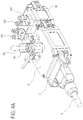
- the perforating electrical contacts 12P may have an elongate shape and comprise one or more conductive teeth (that is, plates or other cutting elements made of a conductive material) at one end, whilst the free end opposite may have the form of gripper, as shown in Figure 6A .
- the conductive teeth of the respective perforating electrical contact perforate the sheath thus connecting electrically the wire and the perforating electrical contact.
- the perforating contacts may be positioned, for example, in the covering element 12D and be movable with it.
- the fast wiring multipolar connector 12 has a first body 12A and a second body 12B.
- the first body 12A has a support with two opposite faces which may comprise at least one printed circuit board, or two or more printed circuit board rigidly and electrically connected to each other.
- Front electrical contacts of a first group of electrical contacts, or contact pins 12C are fixed to one of the faces of the support and can be coupled to corresponding electrical contacts (for example pads, that is to say planar electrical contacts, or holes) of a multipolar socket (for example a socket 7A of the master unit 7 or a socket 6B, 6C of a slave unit 6).
- the contact pins 12C are retractable, or "spring type", that is to say, they are movable elastically independently of each other.
- Electrical contacts of a second group of electrical contacts are fixed to the other face of the support of the first body 12A.
- the second body 12B can be plugged into the first body 12A.
- the electrical contacts of the second group, electrically connected to the contact pins are housed in hollow coupling elements 12E fixed to the respective face of the support.
- the second body 12B has a first and a second end, the latter connected to the cable 8.
- the ends in the form of a gripper of the perforating electrical contacts 12P which, in an embodiment, are housed in protruding coupling elements 12F fixed to the frame. More specifically, the protruding coupling elements 12F can be snap coupled to the hollow coupling elements 12E to plug the second body into the first one and electrically connecting the perforating electrical contacts and the electrical contacts of the first group.
- Figure 6 shows only one half of a protective casing, of known type, for the fast wiring connector.
- the master unit 7 has a clock and each slave unit 6 has its own clock.
- the main processor 7S of the master unit 7 is programmed to generate a synchronisation signal and to transmit the synchronisation signal through the multipolar cable 8, synchronising the clocks of the slave units 6 with the clock of the master unit 7.
- each slave unit 6 has its own unique address which may be detected by the master unit 7 through the multipolar cable 8.
- slave unit 6 (or slave units 6), the following should be considered.
- the slave unit 6 comprises a first electronic bo printed circuit board ard 6D connected to the first socket 6B and to the second socket 6C and configured for managing data transmission through the multipolar cable 8.
- the first printed circuit board 6D comprises a processor (for example a CPU).
- the slave unit 6 comprises a second printed circuit board 6E connected to the first printed circuit board 6D and to the external port 6A and adapted for managing the transit of operational signals through the corresponding input channel 4.
- the second printed circuit board 6E comprises a further, relative processor; alternatively, the second printed circuit board 6E my use the processor of the first printed circuit board 6D (and is free of its ownprocessor).
- the first printed circuit board 6D is the same for all the slave units 6, both in terms of software and hardware.
- the second electronic board 6E preferably has a configuration (hardware and/or software) which depends on the function performed by the slave unit in which it is mounted.
- the slave unit 6 comprises a protective shell 6F, containing the memory 6R, the secondary processor 6S, the first printed circuit board 6D and the second printed circuit board 6E.
- the protective shell 6F defines a seal equal to or greater than IP65 rating .
- the protective shell 6F comprises a first side wall 6G on which is positioned the first socket 6B and a second side wall 6H on which is positioned the second socket 6C.
- the protective shell 6F also comprises an upper wall 6I on which is positioned at least one external port 6A.
- the external port 6A of the slave unit 6 is enabled both for transmitting and receiving operational signals.
- the slave unit 6 is connectable, by means of the external port 6A, to one or more sensors 15 present in the work space 3C of the machine tool 3.
- the term "sensor” identifies for example a measurement head with a position transducer, a vibrations sensor or an acoustic sensor. These sensors are adapted to generate signals representing parameters relative to the machining performed by the machine tool 3, detected during the operation of the machine 3.
- the slave unit 6 is connectable to the sensors 15 for acquiring these signals.
- the slave unit 6 is also connectable to actuators adapted to receive control signals transmitted by the slave unit 6.
- the slave units 6 comprise an electronic circuit for generating an alternating electric excitation signal, and all the alternating electric excitation signals are synchronised in time with each other.
- Each of the two or more slave units 6 is programmed to transmit as output the alternating electric excitation signal through the respective external port 6A, in order to energise the corresponding measuring transducer made with a variable inductive coupling.
- each of the two or more slave units 6 comprises a generator of a first and a second digital PWM (pulse width modulation) signal.
- Each of these two or more slave units 6 comprises processing circuits adapted to receive the first and second digital PWM signals and to process them to generate the alternating electric excitation signal consisting of a sinusoid.
- the generation of the sinusoid for exciting the transducer is achieved with a digital technique, according to which two PWM digital signals are generated.
- the PWM signals are summed and/or subtracted, or in any case combined according to a mathematical function; the signal resulting from that sum or subtraction or combination is filtered to generate the sinusoid.
- This technique make it possible to obtain a sinusoid with a very low level of harmonic distortion, thanks to the possibility of conveniently modulating the duration of the two PWM digital signals. It should also be noted that the use of a digital device facilitates the synchronisation of the generation of the sinusoid with signals coming from the outside.
- the electronic circuits for generating the alternating electric excitation signal are configured to correct the alternating electric excitation signal in phase, preferably at predetermined regular time intervals, in order to synchronise it in phase with another alternating electric excitation signal generated by another slave unit 6.
- each slave unit 6 has a timer to generate a reference signal (for example a square wave), which is used to generate the sinusoid (for example using one or more PWM signals).
- a reference signal for example a square wave
- each slave unit 6 has a clock (connected to the timer) and all the clocks are synchronised, the slave unit 6 is programmed to vary over time the frequency of the reference signal, to phase all the reference signals of all the slave units 6 (all those designed to generate reference signals), since they are synchronised with a reference signal generated by the master unit or with the reference signal generated by one of the slave units (selected in an arbitrary way as a reference for the others). As a result, the sinusoids generated by all the slave units are synchronised with each other.
- each slave unit 6 is configured for acquiring, through the external port 6A, at least one operational signal.
- the operational signal may be a digital signal comprising data, or an analogue signal representing the trend of quantity and therefore having an information content.
- each slave unit 6 is configured to store the operational signal and is programmed to assign to the data acquired through the external port 6A corresponding acquisition instants, on the basis of a relative clock.
- the data acquired by the devices 15 are stored in the slave units 6 and transmitted according to a communication protocol to the master unit 7.
- a corresponding timing information detected by the high precision clock present in each slave unit is associated to the data acquired.
- the timing information is sent to the master unit 7 associated with the data acquired.
- the master unit 7 allows (in combination with the fact that the clocks of the slave units 6 are synchronised with that of the master unit) the master unit 7 to collect data coming from different slave units 6 and to correlate them in time with each other, either in real time (this is particularly useful for the in-process checking) or a posteriori.
- each slave unit on 6 is programmed for storing, for a predetermined interval of time, the data acquired through the external port 6A.
- each slave unit 6 is programmed for storing the data in a data packet and is programmed to transmit at least the data packet to the master unit 7, through the multipolar cable 8.
- the slave units 6 of the plurality of slave units 6 can be connected together to form a modular structure.
- the first socket 6 of the slave unit 6B is male and the second socket 6C is female.
- the first socket 6B of a first slave unit can be coupled to a second socket 6C of a second slave unit; the second socket 6C of a first slave unit can be coupled to a first socket 6B of a second slave unit.
- the first slave unit has the first socket 6B coupled to one of the multipolar connectors 9 of the multipolar cable 8 and the second socket 6C connected, for example directly coupled, to the first socket 6B of the second slave unit; the second socket 6C of the second slave unit is coupled to one of the multipolar connectors 9 of the multipolar cable 8.
- the slave units 6 are not connected with each other by coupling the respective sockets 6B, 6C, they may be connected using the multipolar cable 8.
- the multipolar cable 8 comprises two or more pieces, each having a first and a second end equipped with a multipolar connector 9, to connect to each other the slave units 6 and/or to connect at least one slave unit 6 with the master unit 7.
- slave unit identifies a unit which interfaces a device, such as a sensor, with a network comprising at least one slave unit and the master unit 7 connected by the multipolar cable 8.
- the slave unit is able to perform basic processing such as filtering and/or conditioning a signal or even more complex operations.
- the slave unit 6 is able to autonomously process control signals for an actuator connected to it, even as a function of a signal detected by a sensor connected to the slave unit.
- the system 1 may comprise at least one ancillary unit 10, provided with a first socket 10A and a second socket 10B.
- the first socket 10A and the second socket 10B of the ancillary unit 10 are configured to connect at least to one of the first socket 6B and second socket 6C of the slave unit 6.
- the ancillary unit 10 differs from the slave unit 6 due to the fact that it has a reduced processing and/or communication capacity.
- the slave unit 6 has, as well as a memory, a processor which allows to perform complex processing and exchange data through a complex and fast communication channel (for example Ethernet).
- a complex and fast communication channel for example Ethernet
- the ancillary unit 10 does not have a processor, that is, a data processing system; alternatively, the ancillary unit 10 can have its own processing means, consisting for example of a programmable logic.
- the ancillary unit 10 is equipped with its ownmemory.
- the ancillary unit 10 may not have access to any communication channel defined by the multipolar cable 8, or may be configured for exchanging data through a communication channel defined by the multipolar cable 8, preferably of lower ranking than the communication channel used by the slave units (for example, a CAN or RS485 communication channel).
- At least one operation of the ancillary unit 10 is controlled by an operation of the slave unit to which it is connected.
- a relative ancillary unit 10 may comprise a solenoid valve and a connecting element 10C for a compressed air circuit, to retract the measuring feeler in a per se known step of a checking cycle.
- the multiple multipolar connector 16 which does not have an external port for connection to a device 15, itself defines an ancillary unit 10.
- the ancillary unit 10 might consist of a voltage amplifier, connectable to an external electrical power source, to provide an output supply voltage higher than the input voltage.
- This type of ancillary unit 10 does not have a memory and processor.
- the master unit 7 comprises a first socket 7A and a second socket 7B.
- each of the sockets may comprise planar electrical contacts or "pads" which can be coupled to respective retractable electrical contacts present in multipolar connectors.
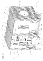
- the master unit 7 has the shape generically of a parallelepiped with a front wall 7C, a back wall 7F and a bottom wall 7T.
- the first socket 7A and the second socket 7B are positioned in the front wall 7C of the master unit 7.
- the master unit 7 comprises elastic snap-on locking elements (not shown, per se known and located on the back wall 7F) which are configured to fix the master unit 7 to a supporting or mounting bar of the electrical panel, for example a DIN rail.
- the first socket 7A and the second socket 7B of the master unit 7 are positioned on opposite sides of the front wall 7C, respectively close to a first outer side wall 7D and a second outer side wall 7E of the master unit 7.
- the first socket 7A and the second socket 7B of the master unit 7 are positioned at the same height, that is to say, at a same distance from the bottom wall 7T of the master unit 7.
- the master unit 7 has flat side walls 7D, 7E and a plurality of fins 17 which protrude from the side walls 7D, 7E.
- the function of the fins 17 is to favour heat exchange and thus the cooling of the master unit 7.
- the fins 17 are parallel to each other and perpendicular to the bottom wall 7T of the master unit 7.
- the fins are oriented vertically.
- the fins 17 are arranged perpendicularly to the locking elements of the master unit 7 to a support.
- the fins are oriented perpendicularly to the locking elements on the back wall 7F for connection to the DIN rail.
- top surface of the master unit 7 is also provided with fins.
- the master unit 7 also comprises a cooling fan (not illustrated) positioned in a space inside the master unit 7.
- the purpose of the cooling fan is to make uniform the temperature inside the master unit 7 and it cooperates with the fins 17 to cool the electronic components housed in the master unit 7.
- the master unit 7 comprises a power supply socket 7G, a network socket 7H, a field bus socket 7I adapted to couple to a further multipolar signal connector, one or more alarm warning lights 7L, a peripheral port 7M for a connection to a display which is remote or can be made remote.
- the master unit can also comprise one or more USB 7N and/or USB On-The-Go 7P ports (also known as USB OTG) and/or a HDMI 7Q port.
- the electricity supply socket 7G, the network socket 7H, the field bus socket 71, the alarm warning lights 7L, the peripheral port 7M, the USB ports 7N, 7P and the HDMI port 7Q are positioned on the front wall 7C of the master unit 7.
- the main processor 7S is programmed to divide a data transmission time interval into a plurality of time slots and to uniquely assign to each slave unit 6 a corresponding time slot of the plurality of time slots.
- the secondary processor 6S can be set for transmitting data through the multipolar cable 8 only within the respective time slot.
- the main processor 7S is programmed to assign to each slave unit 6 a unique identification code and it is programmed to perform a continuous data collection cycle.
- the main processor 7S in every data transmission time interval, is configured to receive and store the data transmitted from the corresponding slave unit 6.
- the main processor 7S is also configured for associating the data with the slave unit 6 which they come from.
- each slave unit 6 (and, if necessary, the ancillary units 10 equipped with processing means) has a first and a second switch; the first switch is positioned between the first socket 6B and the processor, the second switch is positioned between the second socket 6C and the processor.
- the first and second switches could be conventional electrical switches, but preferably they are electronic switches that are made by means of appropriate circuits and can be actuated via software (for example from the sockets 6B, 6C).
- the first switch is set in the closed position and the second switch is set up in the open position.
- the multiple connector 16 has a first, a second and a third switch; in this case the first switch is set in the closed position and the second and the third switches are set in the open position.
- the step of configuring the system is started, for example by means of the procedure which follows.
- the master unit 7 sends a (first) signal, through the multipolar cable 8, towards the first slave unit 6 of the chain defined by the system 1; the signal constitutes an interrogation and is received by the processor of the (first) slave unit 6 through the corresponding first switch (the signal does not continue further because the second switch of the first slave unit 6 is open).
- the processor replies to the interrogation (because the slave unit 6 is programmed to provide the response to the interrogation) by providing details regarding its existence and the function of the slave unit 6.
- the master unit 7 receives the response, records it and stores the position and the function of the slave unit 6 and assigns to the slave unit 6 a unique identification code.
- the slave unit 7 transmits a control signal to the processor of the (first) slave unit 6, for switching the second switch from the open position to the closed position.
- the master unit 7 sends a (second) signal through the multipolar cable 8, which, like the first one, constitutes an interrogation for a processor.
- the signal is received by the processor of the second slave unit 6 (the first slave unit downstream with respect to the first slave unit 6) through the corresponding first switch (the signal does not continue further because the second switch of the second slave unit 6 is open).
- the slave unit 6 it is sufficient for the slave unit 6 to comprise at least one switch, in particular the second switch positioned facing away from the master unit 7. Indeed, in an embodiment of the invention, the first switch mentioned above may remain closed and be replaced by a permanent electrical connection.
- the main processor 7S is programmed to divide the data transmission time intervalinto a number of time slots greater than the number of slave units 6 of the system 1, saving at least one additional or extra time slot (in addition to the time slots corresponding to respective slave units 6 and uniquely assigned to them).
- the main processor 7S is programmed to set parameters of the slave units 6 through the multipolar cable 8.
- the main processor 7S is programmed to re-set valid parameters for the slave units 6, such as, for example, the duration of the data transmission time interval, and/or to perform the downloading of a digital document in the processor of the slave unit 6.
- the additional time interval can also be exploited by using, for example, a file transfer protocol such as FTP.
- the master unit 7 comprises a diagnostic block having electronic circuits.
- the diagnostic block is configured for detecting or collecting, for the slave units 6 and/or for the master unit 7, at least one power supply parameter, representing a supply voltage.
- the diagnostic block is configured for collecting, in addition or alternatively to the power supply parameter, for each slave unit 6 and/or for the master unit 7, an internal temperature.
- a temperature sensor may be present in each slave unit 6 and/or in the master unit 7 for providing a value relative to the internal temperature.
- the diagnostic block of the master unit 7 is configured to collect, for the slave units 6 and/or for the master unit 7, one or more of the following parameters: power supply voltage, electrical current draw, power draw.
- the diagnostic block can detect or collect at least one power supply parameter relative to the entire system (that is, the slave units 6 and the master unit), only to the master unit 7 or to each slave unit 6.
- the diagnostic block is also able to collect, alternatively or in addition to the power supply parameter, a temperature inside the single slave unit 6 and/or the master unit 7.
- the diagnostic block of the master unit 7 is programmed for storing data representing a trend over time of the power supply parameter and/or the internal temperature detected.
- the diagnostic block of the master unit 7 has stored in its memory one or more reference values of the power supply parameter and/or internal temperature.
- the diagnostic block is programmed to compare values, preferably detected in real time, of the power supply parameter and/or internal temperature with the reference values.
- the diagnostic block is preferably programmed to generate an alarm depending on the comparison carried out. For example, the diagnostic block is programmed to generate an alarm if the internal temperature exceeds a reference value for a predetermined time. In an embodiment, the diagnostic block is programmed to generate an alarm if the power supply parameter differs from a reference value for a predetermined time.
- the slave unit 6 is programmed to transmit in synchrony to the master unit 7 data relating to the operational signals and data relating to the at least one power supply parameter and/or internal temperature.
- the master unit 7 is configured to perform the most complex mathematical operations requested by the various measuring cycles and it has the duty of interpreting and/or combining the information received from the various sensors (by means of the slave units 6), translating them into signals that can be received and processed by the numerical control unit 2 and, generally speaking, it is the only interlocutor (within the system 1) of the numerical control unit 2.
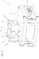
- the system 1 comprises a connector bridge 11 having a first and a second end.
- the bridge connector 11 comprises a first connector 11A at the first end and a second connector 11B at the second end.
- Each of the first and second connectors 11A, 11B comprises electrical contacts and can be coupled to the first or to the second socket of the master unit 7.
- the connector bridge 11 comprises asymmetrically shaped profiles (which define mechanical keys) and the sockets 7A, 7B with which the connector bridge 11 is designed to be coupled have corresponding shaped profiles adapetd to cooperate with the shaped profiles of the connector bridge 11 to facilitate the correct positioning of the connector bridge in a step of alignment of these shaped profiles.
- the connector bridge 11 comprises a rim made of insulating material (that is, made of electrical or dielectric insulating material), with a central opening and an edge which can be positioned around the electrical contacts of the first or second connector 11A, 11B.
- the function of the insulating rim is to prevent accidental short circuits during positioning of the connector bridge 11.
- the connector bridge 11 has mainly the function of connecting a first and a second unit, in particular the master unit 7 to at least one other unit which defines a supplementary unit 13 equipped with a front wall with at least one socket.
- the first and second connector 11A, 11B have spring contacts, that is to say, retractable contacts, adapted to touch planar electrical contacts or "pads" of the respective sockets. This makes it possible to annul mechanical clearances and compensate for positioning errors between the units to be connected together.
- the edge delimiting an area occupied by the spring contacts is raised; this is to protect the contacts in the case of accidental impact.
- the first and second connector 11A, 11B face the same direction (along axes parallel to each other and spaced), located on the same side of the bridge connector. That makes it possible to connect the front of the connector bridge 11 to the units positioned alongside as the first and second connectors 11A, 11B face the front wall of the master unit 7 and the supplementary unit 13 where the respective sockets are defined.
- This front position of the connector bridge 11 makes it possible to remove the connector bridge 11, and pull out the master unit 7 or a supplementary unit 13, without moving the other unit or the master unit 7 (that is to say, the one which must not be removed).
- the bridge connector 11 comprises fastening elements associated with the first and the second connector 11A, 11B with retractable contacts. More specifically, fastening screws are coupled to holes defined in the connector bridge 11 and are inserted in corresponding holes of the front wall where the socket to which the connector 11A, 11B must be coupled is defined, so as to guarantee the correct and stable connection of the connector bridge 11.
- the connector bridge 11 is equipped with an LED visible from the outside, which light up and visually indicates when the bridge connector is connected.
- the first and the second connector 11A, 11B of the bridge connector 11 are connected rigidly, for example by means of a main body 11C.
- the first and the second connector 11A, 11B are positioned at a mutual distance D1 which is greater than twice the distance D2 which separates the first socket 7A or the second socket 7B of the master unit 7 from an outer side wall 7D, 7E of the master unit 7.
- the supplementary unit 13 may be, for example, a further master unit provided with its own network of slave units or an input/output module of the digital or analogue type or even a slave unit.
- the supplementary unit 13 has a first socket 13A and a second socket 13B.
- each of the sockets may comprise planar electrical contacts or "pads" which can be coupled to respective retractable electrical contacts present in the multipolar connectors of the connector bridge 11.
- the supplementary unit 13 has the shape generically of a parallelepiped and the first socket 13A and the second socket 13B are positioned on opposite sides of a front wall 13C, respectively close to a first outer side wall 13D and a second outer side wall 13E of the supplementary unit 13.
- the supplementary unit 13 has flat side walls 13D, 13E and a plurality of fins 17' which protrude from the side walls 13D, 13E.
- the fins 17 are parallel to each other and arranged perpendicularly to a bottom wall 13T of the supplementary unit 13.
- the fins 17' are oriented perpendicularly to fastening elements positioned on a back wall 13F of the supplementary unit.
- the fins 17, 17' present on a side wall of the master unit 7 and on a side wall of the supplementary unit 13 cooperate to form cooling ducts 14 arranged vertically which enhance dissipation of the hot air using the so-called “chimney or stack effect” to optimise the heat exchange (that is, the cooling) of the master unit 7 and the supplementary unit 13.
- the supplementary unit is also preferably provided with fins at a top surface.
- the multipolar cable 8 comprises at least a first bundle of signal wires, which are intended for a corresponding communication channel and one or more power supply wires.
- the multipolar cable 8 defines a plurality of communication channels, preferably of different rankings in terms of speed and complexity of the communication.
- the multipolar cable 8 preferably defines a first communication channel (high ranking, for example Ethernet), a second communication channel (intermediate ranking, for example CAN) and a third communication channel (low ranking, for example RS485).
- the multipolar cable 8 comprises a plurality of signal wires, for example four, for the first communication channel; a plurality of signal wires, for example two, for the second communication channel; a plurality of signal wires, for example, two, for the third communication channel.
- the first channel is used, for example, for data transmission between the slave units 6 and the master unit 7.
- the second channel is used, for example, for transmitting data between the ancillary units 10 provided with processing means and the master unit 7 of one or more slave units 6.
- the third channel is used, for example, for transmitting trigger signals, that is, pulse signals constituting operational commands transmitted by the master unit 7 to the slave units 6 or ancillary units 10.
- the conducting multipolar cable 8 comprises one or more wires for transmitting logic type signals.
- the multipolar cable 8 comprises one or more wires for distributing electrical power supply in the network of the system 1.
- the multipolar cable 8 comprises a plurality of power supply wires (for example, three) at a first voltage value (for example the positive DC voltage of 24 V), and preferably a further plurality (for example, three) of reference power supply wires (for example GND of the 24 V DC).
- the present invention also relates to a method for processing and transmitting data between a numerical control unit 2 adapted to control a machine tool 3 and one or more devices present in the machine tool 3.
- the method comprises the following steps:
- synchronization signal may mean, for example, a data packet generated and transmitted inside the communication channel, for example the Ethernet network.
- the method comprises the following steps:
- the correction of a relative phase displacement between the alternating electric excitation signals is obtained by continuously varying the clock frequency of the slave units 6.
- the alternating electric excitation signals are sinusoids generated by processing a first and a second digital PWM (pulse width modulation) signals having suitable pulse-duration modulation. More specifically, the processing comprises a sum of the first and second digital signal PWM and a subsequent filtering.
- the method comprises one or more of the following steps:
- the method comprises the following steps:
- the configuration step comprises a step of assigning to each slave unit 6 a unique identification code, with the following steps:
- the step of arranging the network comprises connecting two or more slave units 6 connecting the second socket 6C of a slave unit 6 and the first socket 6B of another slave unit 6.
- the mutual connection of two slave units 6 may be performed by connecting directly the respective sockets or by using the multipolar cable 8.
- the step of arranging the network comprises connecting at least one slave unit 6 to one or two ancillary units 10 provided with a first socket 10A and a second socket 10B.
- the first and second socket 10A, 10B of each ancillary unit 10 is configured to be coupled to a first or a second connector of the multipolar connectors 9 and to one of the first and second sockets 6B, 6C of the slave unit 6.
- an operation of the ancillary unit 10 is controlled by an operation of the slave unit 6 to which it is connected.
- the multipolar cable 8 comprises two or more pieces, each having a first and a second end provided with a multipolar connector 9, the mutual connection of two slave units 6 is carried out by means of one of the pieces.
- the step of arranging the network comprises making a configuration of the "daisy chain" type.
- the arrangment of the network comprises making a branch, with respect to the configuration of the "daisy chain" type, through a multipolar connector coupled to one of the multipolar connectors 9 of the multipolar cable 8 and/or connected to the first or the second socket 6B, 6C of the slave unit 6.
- the step of arranging the network comprises connecting a first unit to a second unit, that is to say the master unit 7 to a supplementary unit 13 provided with at least one socket 13A through a bridge connector 11 having a first connector 11A and a second connector 11B which can be coupled to the first or to the second socket 7A, 7B of the master unit 7.
- the connector bridge 11 is rigid and U-shaped with the two multipolar connectors 11A, 11B placed at the ends.
- the electrical connection of the master unit 7 to the supplementary unit 13 comprises coupling the bridge connector 11 to one of the sockets 7A, 7B of the master unit 7 and to one of the sockets 13A, 13B of the supplementary unit 13.
- the method comprises a step of connecting the master unit 7 and the supplementary unit 13 to the same supporting bar.
- the master unit 7 and the supplementary unit 13 are positioned alongside of each other. Subsequently, the master unit 7 and the supplementary unit 13 are connected electrically by means of the bridge connector 11.
- the electrical connection comprises positioning the bridge connector 11 in such a way that the retractable contacts touch corresponding planar electrical contacts of the sockets of the master unit 7 and the supplementary unit 13, and defining and fixing the position of the bridge connector 11 with respect to to the master unit 7 and the supplementary unit 13 by means of fastening elements.
- a step of disconnecting, for example to replace a supplementary unit 13 alongside the master unit 7, comprises removing the fastening elements and unplugging the bridge connector 11 to detach the retractable contacts of the bridge connector 11 from the planar electrical contacts of the sockets of the two units, and removing the unit to be replaced, for example the supplementary unit 13, pulling it from the front without the need to move the master unit 7.
- This is particularly advantageous when there are several units side by side and electrically connected by connector bridges, and a unit flanked by other units is to be replaced.
- the steps for electrical connection and disconnection are part of a method for managing electrical connections according to the invention, which is generally applicable to measuring and/or checking systems.
- the network comprises at least one slave unit 6 positioned in the work space 3C of the machine tool 3.
- the master unit 7 and any supplementary unit(s) 13 are generally positioned in an electrical panel.
- the method comprises the steps of:
- the method preferably comprises the following steps:
- the data transmission time interval is divided into a number of time slotsgreater than the number of slave units 6 of the system 1, to keep at least one additional or extra time slot (as well as the time slots assigned to the slave units 6) which may be used by the master unit 7 to set parameters, during the continuous data collection cycle, the slave units 6.
- the data transmission, the electrical power supply of slave unit 6 and the synchronization of the clock of each slave unit 6 with the clock of the master unit 7 are carried out by means of the multipolar cable 8.
- the method comprises a step of acquiring and storing, by the slave unit 6, data corresponding to at least one operational signal received through the input channel 4 (that is, the port 6A) and a step of assigning corresponding acquisition instants to the data acquired.
- the method also comprises a step of detecting or collecting, by the master unit 7, at least one power supply parameter (voltage or current, for example) representing the electrical current draw in the entire system, in only the master unit 7 or in each slave unit 6.
- at least one power supply parameter voltage or current, for example
- the method also comprises a step for collecting, by the master unit 7, an internal temperature of one or more (preferably all) the slave units 6 and/or the master unit 7.
- the master unit 7 detects or collects one or more of the following parameters for the slave units 6 and/or for the master unit 7: supply voltage, electrical current draw, absorbed power.
- the method comprises a step of comparing detected parameters of power supply and/or internal temperature with reference values.
- the method also comprises a step of generating alarm signals as a function of such comparison.
- the at least one slave unit 6 transfers in synchrony to the master unit 7 data relating to the operational signals and data relating to the power supply parameter and/or to the internal temperature.
- the multipolar cable 8 has at least one connectorless end, that is one end without a connector (a free end).
- a method according to the present invention to connect, in a generic measuring and/or checking system, at least a first and a second unit using the multipolar cable 8 comprises the following steps:
- the step of positioning the multipolar cable comprises the insertion of the end without a connector in a machine cable carrying duct of the machine tool 3 and, after the insertion, a step of coupling a fast wiring multipolar connector 12 to the free end.
- the coupling of the fast wiring multipolar connector 12 to the free end of the multipolar cable 8 comprises a step of perforating the insulating sheath which covers the sheathed wires 8A contained in the multipolar cable 8, by means of perforating electrical contacts 12P present in the fast wiring multipolar connector 12.
- the fast wiring multipolar connector 12 is then connected to the master unit 7.
- the master unit 7 is positioned in the space 3D of the electrical panel.
- the end with a pre-assembled multipolar connector of the multipolar cable 8 is positioned in the work space 3C.
- slave unit 6 The end with a pre-assembled multipolar connector of the multipolar cable 8 is connected to a slave unit 6.
- other slave units 6 and/or ancillary units 10 are connected to the slave unit 6, either directly or by means of further pieces of multipolar cable 8.
- other slave units 6 and/or ancillary units 10 are positioned in the work space 3C of the machine tool 3.
Landscapes
- Engineering & Computer Science (AREA)
- Microelectronics & Electronic Packaging (AREA)
- Automation & Control Theory (AREA)
- Manufacturing & Machinery (AREA)
- Arrangements For Transmission Of Measured Signals (AREA)
- Machine Tool Units (AREA)
- Connections By Means Of Piercing Elements, Nuts, Or Screws (AREA)
- Details Of Connecting Devices For Male And Female Coupling (AREA)
Applications Claiming Priority (2)
| Application Number | Priority Date | Filing Date | Title |
|---|---|---|---|
| ITUB2015A003294A ITUB20153294A1 (it) | 2015-08-31 | 2015-08-31 | Sistema di misura e/o controllo con almeno due unita', e metodo per collegare le due unita' |
| PCT/EP2016/070459 WO2017037087A1 (en) | 2015-08-31 | 2016-08-31 | Measuring and/or checking system including at least two units, and method to connect such units |
Publications (2)
| Publication Number | Publication Date |
|---|---|
| EP3345468A1 EP3345468A1 (en) | 2018-07-11 |
| EP3345468B1 true EP3345468B1 (en) | 2021-11-03 |
Family
ID=54843926
Family Applications (1)
| Application Number | Title | Priority Date | Filing Date |
|---|---|---|---|
| EP16760045.1A Active EP3345468B1 (en) | 2015-08-31 | 2016-08-31 | Measuring and/or checking system including at least two units, and method to connect such units |
Country Status (6)
| Country | Link |
|---|---|
| US (1) | US10396487B2 (enExample) |
| EP (1) | EP3345468B1 (enExample) |
| JP (1) | JP6946271B2 (enExample) |
| CN (1) | CN107926133B (enExample) |
| IT (1) | ITUB20153294A1 (enExample) |
| WO (1) | WO2017037087A1 (enExample) |
Families Citing this family (5)
| Publication number | Priority date | Publication date | Assignee | Title |
|---|---|---|---|---|
| CN110391576B (zh) * | 2019-08-22 | 2024-06-28 | 中国工程物理研究院电子工程研究所 | 特殊环境电缆插头插座拆装专用工具 |
| DE102020123853A1 (de) * | 2019-09-20 | 2021-03-25 | Tyco Electronics France Sas | Befestigungsvorrichtung |
| CN110678009B (zh) * | 2019-09-29 | 2021-04-06 | 中国科学院长春光学精密机械与物理研究所 | 一种连接器定位装置 |
| JP7390184B2 (ja) * | 2019-12-26 | 2023-12-01 | Thk株式会社 | センサ及び、このセンサを備える運動案内装置 |
| IT202100002711A1 (it) * | 2021-02-08 | 2022-08-08 | Te Connectivity Solutions Gmbh | Involucro protettivo di schiuma per connettori per frigoriferi |
Family Cites Families (19)
| Publication number | Priority date | Publication date | Assignee | Title |
|---|---|---|---|---|
| JPS61133584A (ja) * | 1985-10-31 | 1986-06-20 | アンプ インコ−ポレ−テツド | 電気コネクタ用プラグ |
| DE4207402C2 (de) * | 1992-03-09 | 1994-05-19 | Wieland Elektrische Industrie | Steckverbinder für speicherprogrammierbare Steuerungen |
| JPH1013394A (ja) * | 1996-06-21 | 1998-01-16 | Fanuc Ltd | 通信における同期方法 |
| DE19743972A1 (de) | 1997-10-06 | 1999-04-29 | Phoenix Contact Gmbh & Co | Elektronisches Ein-/Ausgabemodul |
| JPH11299291A (ja) * | 1998-04-16 | 1999-10-29 | Sanyo Denki Co Ltd | 多軸モータ制御装置 |
| US5947761A (en) * | 1998-09-29 | 1999-09-07 | The Whitaker Corporation | Electrical connector with pivoting wire fixture |
| US7156688B2 (en) * | 2002-05-31 | 2007-01-02 | Molex Incorporated | Insulation displacement connector |
| US6752647B1 (en) * | 2003-05-02 | 2004-06-22 | Jyh Eng Industrial Co., Ltd. | Rotary insulation displacement connector |
| JP4343212B2 (ja) * | 2006-11-27 | 2009-10-14 | ファナック株式会社 | データ送受信方式 |
| US7503810B1 (en) * | 2007-09-12 | 2009-03-17 | Commscope, Inc. Of North Carolina | Board edge termination back-end connection assemblies and communications jacks including such assemblies |
| EP2258153B1 (de) * | 2008-03-28 | 2017-08-02 | FESTO AG & Co. KG | Elektrisches baukastenmodulsystem mit einem variabel einsetzbaren feldbusmodul |
| TWM349123U (en) * | 2008-06-18 | 2009-01-11 | Surtec Ind Inc | Socket structure for communication cable |
| DE202009010037U1 (de) * | 2009-07-23 | 2010-12-23 | Weidmüller Interface GmbH & Co. KG | Steckerverbindung aus zusammensteckbaren Steckverbindern |
| CN201594669U (zh) * | 2009-12-11 | 2010-09-29 | 富港电子(东莞)有限公司 | 微型同轴连接器 |
| EP2466697B1 (de) * | 2010-12-17 | 2020-01-22 | LEONI Kabel GmbH | Datenkabelanschlussmodul sowie ein Verfahren zu dessen Konfektion an einem Kabel |
| CN202159250U (zh) * | 2011-07-19 | 2012-03-07 | 无锡星月科技有限公司 | 蜗杆砂轮磨齿机数控系统 |
| EP2645491B1 (de) * | 2012-03-29 | 2017-02-01 | Siemens Aktiengesellschaft | Netzwerkanschlußstecker und Steckverbindung |
| US20140273605A1 (en) * | 2013-03-12 | 2014-09-18 | Telebox Industries Corp. | Connector |
| WO2015007939A2 (es) * | 2013-07-15 | 2015-01-22 | Te Connectivity Amp España, S.L.U. | Conector macho de telecomunicaciones para aplicaciones de alta tasa de datos |
-
2015
- 2015-08-31 IT ITUB2015A003294A patent/ITUB20153294A1/it unknown
-
2016
- 2016-08-31 US US15/755,825 patent/US10396487B2/en active Active
- 2016-08-31 EP EP16760045.1A patent/EP3345468B1/en active Active
- 2016-08-31 WO PCT/EP2016/070459 patent/WO2017037087A1/en not_active Ceased
- 2016-08-31 JP JP2018510923A patent/JP6946271B2/ja active Active
- 2016-08-31 CN CN201680050522.XA patent/CN107926133B/zh active Active
Non-Patent Citations (1)
| Title |
|---|
| None * |
Also Published As
| Publication number | Publication date |
|---|---|
| JP6946271B2 (ja) | 2021-10-06 |
| CN107926133B (zh) | 2020-11-17 |
| US10396487B2 (en) | 2019-08-27 |
| WO2017037087A1 (en) | 2017-03-09 |
| EP3345468A1 (en) | 2018-07-11 |
| US20180331457A1 (en) | 2018-11-15 |
| ITUB20153294A1 (it) | 2017-03-03 |
| CN107926133A (zh) | 2018-04-17 |
| JP2018538652A (ja) | 2018-12-27 |
Similar Documents
| Publication | Publication Date | Title |
|---|---|---|
| EP3345061B1 (en) | Data processing and transmission system and method | |
| EP3345468B1 (en) | Measuring and/or checking system including at least two units, and method to connect such units | |
| EP3345469B1 (en) | Measuring and/or checking system including at least two units, and method to manage relative electrical connections | |
| US8274782B2 (en) | Motor control center network connectivity method and system | |
| EP3345062B1 (en) | Data processing and transmission system and method | |
| JP2000509206A (ja) | 自動構築型電気接続部を有するモジュール拡張式モジュラー型周辺装置 | |
| US12114458B2 (en) | Power distribution unit with a modular construction | |
| WO2017037086A1 (en) | Data processing and transmission system and method | |
| JP2000509207A (ja) | 自己支持構造のモジュール拡張式モジュラー型周辺装置 | |
| WO2021061008A1 (ru) | Контролирующий пункт ввода-вывода дискретных сигналов | |
| RU198149U1 (ru) | Процессорный блок промышленного программируемого контроллера | |
| RU2749103C1 (ru) | Промышленный программируемый контроллер | |
| JPH1063977A (ja) | 電子システム | |
| IT202000010999A1 (it) | Dispositivo elettromeccanico | |
| GB2385948A (en) | Switchgear cabinet monitoring and control system |
Legal Events
| Date | Code | Title | Description |
|---|---|---|---|
| STAA | Information on the status of an ep patent application or granted ep patent |
Free format text: STATUS: THE INTERNATIONAL PUBLICATION HAS BEEN MADE |
|
| PUAI | Public reference made under article 153(3) epc to a published international application that has entered the european phase |
Free format text: ORIGINAL CODE: 0009012 |
|
| STAA | Information on the status of an ep patent application or granted ep patent |
Free format text: STATUS: REQUEST FOR EXAMINATION WAS MADE |
|
| 17P | Request for examination filed |
Effective date: 20180403 |
|
| AK | Designated contracting states |
Kind code of ref document: A1 Designated state(s): AL AT BE BG CH CY CZ DE DK EE ES FI FR GB GR HR HU IE IS IT LI LT LU LV MC MK MT NL NO PL PT RO RS SE SI SK SM TR |
|
| AX | Request for extension of the european patent |
Extension state: BA ME |
|
| DAV | Request for validation of the european patent (deleted) | ||
| DAX | Request for extension of the european patent (deleted) | ||
| STAA | Information on the status of an ep patent application or granted ep patent |
Free format text: STATUS: EXAMINATION IS IN PROGRESS |
|
| 17Q | First examination report despatched |
Effective date: 20191004 |
|
| GRAP | Despatch of communication of intention to grant a patent |
Free format text: ORIGINAL CODE: EPIDOSNIGR1 |
|
| STAA | Information on the status of an ep patent application or granted ep patent |
Free format text: STATUS: GRANT OF PATENT IS INTENDED |
|
| INTG | Intention to grant announced |
Effective date: 20210608 |
|
| GRAS | Grant fee paid |
Free format text: ORIGINAL CODE: EPIDOSNIGR3 |
|
| GRAA | (expected) grant |
Free format text: ORIGINAL CODE: 0009210 |
|
| STAA | Information on the status of an ep patent application or granted ep patent |
Free format text: STATUS: THE PATENT HAS BEEN GRANTED |
|
| AK | Designated contracting states |
Kind code of ref document: B1 Designated state(s): AL AT BE BG CH CY CZ DE DK EE ES FI FR GB GR HR HU IE IS IT LI LT LU LV MC MK MT NL NO PL PT RO RS SE SI SK SM TR |
|
| REG | Reference to a national code |
Ref country code: GB Ref legal event code: FG4D |
|
| REG | Reference to a national code |
Ref country code: AT Ref legal event code: REF Ref document number: 1445177 Country of ref document: AT Kind code of ref document: T Effective date: 20211115 Ref country code: CH Ref legal event code: EP |
|
| REG | Reference to a national code |
Ref country code: IE Ref legal event code: FG4D |
|
| REG | Reference to a national code |
Ref country code: DE Ref legal event code: R096 Ref document number: 602016065738 Country of ref document: DE |
|
| REG | Reference to a national code |
Ref country code: SE Ref legal event code: TRGR |
|
| REG | Reference to a national code |
Ref country code: LT Ref legal event code: MG9D |
|
| REG | Reference to a national code |
Ref country code: NL Ref legal event code: MP Effective date: 20211103 |
|
| REG | Reference to a national code |
Ref country code: AT Ref legal event code: MK05 Ref document number: 1445177 Country of ref document: AT Kind code of ref document: T Effective date: 20211103 |
|
| PG25 | Lapsed in a contracting state [announced via postgrant information from national office to epo] |
Ref country code: RS Free format text: LAPSE BECAUSE OF FAILURE TO SUBMIT A TRANSLATION OF THE DESCRIPTION OR TO PAY THE FEE WITHIN THE PRESCRIBED TIME-LIMIT Effective date: 20211103 Ref country code: LT Free format text: LAPSE BECAUSE OF FAILURE TO SUBMIT A TRANSLATION OF THE DESCRIPTION OR TO PAY THE FEE WITHIN THE PRESCRIBED TIME-LIMIT Effective date: 20211103 Ref country code: FI Free format text: LAPSE BECAUSE OF FAILURE TO SUBMIT A TRANSLATION OF THE DESCRIPTION OR TO PAY THE FEE WITHIN THE PRESCRIBED TIME-LIMIT Effective date: 20211103 Ref country code: BG Free format text: LAPSE BECAUSE OF FAILURE TO SUBMIT A TRANSLATION OF THE DESCRIPTION OR TO PAY THE FEE WITHIN THE PRESCRIBED TIME-LIMIT Effective date: 20220203 Ref country code: AT Free format text: LAPSE BECAUSE OF FAILURE TO SUBMIT A TRANSLATION OF THE DESCRIPTION OR TO PAY THE FEE WITHIN THE PRESCRIBED TIME-LIMIT Effective date: 20211103 |
|
| PG25 | Lapsed in a contracting state [announced via postgrant information from national office to epo] |
Ref country code: IS Free format text: LAPSE BECAUSE OF FAILURE TO SUBMIT A TRANSLATION OF THE DESCRIPTION OR TO PAY THE FEE WITHIN THE PRESCRIBED TIME-LIMIT Effective date: 20220303 Ref country code: PT Free format text: LAPSE BECAUSE OF FAILURE TO SUBMIT A TRANSLATION OF THE DESCRIPTION OR TO PAY THE FEE WITHIN THE PRESCRIBED TIME-LIMIT Effective date: 20220303 Ref country code: PL Free format text: LAPSE BECAUSE OF FAILURE TO SUBMIT A TRANSLATION OF THE DESCRIPTION OR TO PAY THE FEE WITHIN THE PRESCRIBED TIME-LIMIT Effective date: 20211103 Ref country code: NO Free format text: LAPSE BECAUSE OF FAILURE TO SUBMIT A TRANSLATION OF THE DESCRIPTION OR TO PAY THE FEE WITHIN THE PRESCRIBED TIME-LIMIT Effective date: 20220203 Ref country code: NL Free format text: LAPSE BECAUSE OF FAILURE TO SUBMIT A TRANSLATION OF THE DESCRIPTION OR TO PAY THE FEE WITHIN THE PRESCRIBED TIME-LIMIT Effective date: 20211103 Ref country code: LV Free format text: LAPSE BECAUSE OF FAILURE TO SUBMIT A TRANSLATION OF THE DESCRIPTION OR TO PAY THE FEE WITHIN THE PRESCRIBED TIME-LIMIT Effective date: 20211103 Ref country code: HR Free format text: LAPSE BECAUSE OF FAILURE TO SUBMIT A TRANSLATION OF THE DESCRIPTION OR TO PAY THE FEE WITHIN THE PRESCRIBED TIME-LIMIT Effective date: 20211103 Ref country code: GR Free format text: LAPSE BECAUSE OF FAILURE TO SUBMIT A TRANSLATION OF THE DESCRIPTION OR TO PAY THE FEE WITHIN THE PRESCRIBED TIME-LIMIT Effective date: 20220204 Ref country code: ES Free format text: LAPSE BECAUSE OF FAILURE TO SUBMIT A TRANSLATION OF THE DESCRIPTION OR TO PAY THE FEE WITHIN THE PRESCRIBED TIME-LIMIT Effective date: 20211103 |
|
| PG25 | Lapsed in a contracting state [announced via postgrant information from national office to epo] |
Ref country code: SM Free format text: LAPSE BECAUSE OF FAILURE TO SUBMIT A TRANSLATION OF THE DESCRIPTION OR TO PAY THE FEE WITHIN THE PRESCRIBED TIME-LIMIT Effective date: 20211103 Ref country code: SK Free format text: LAPSE BECAUSE OF FAILURE TO SUBMIT A TRANSLATION OF THE DESCRIPTION OR TO PAY THE FEE WITHIN THE PRESCRIBED TIME-LIMIT Effective date: 20211103 Ref country code: RO Free format text: LAPSE BECAUSE OF FAILURE TO SUBMIT A TRANSLATION OF THE DESCRIPTION OR TO PAY THE FEE WITHIN THE PRESCRIBED TIME-LIMIT Effective date: 20211103 Ref country code: EE Free format text: LAPSE BECAUSE OF FAILURE TO SUBMIT A TRANSLATION OF THE DESCRIPTION OR TO PAY THE FEE WITHIN THE PRESCRIBED TIME-LIMIT Effective date: 20211103 Ref country code: DK Free format text: LAPSE BECAUSE OF FAILURE TO SUBMIT A TRANSLATION OF THE DESCRIPTION OR TO PAY THE FEE WITHIN THE PRESCRIBED TIME-LIMIT Effective date: 20211103 Ref country code: CZ Free format text: LAPSE BECAUSE OF FAILURE TO SUBMIT A TRANSLATION OF THE DESCRIPTION OR TO PAY THE FEE WITHIN THE PRESCRIBED TIME-LIMIT Effective date: 20211103 |
|
| REG | Reference to a national code |
Ref country code: DE Ref legal event code: R097 Ref document number: 602016065738 Country of ref document: DE |
|
| PLBE | No opposition filed within time limit |
Free format text: ORIGINAL CODE: 0009261 |
|
| STAA | Information on the status of an ep patent application or granted ep patent |
Free format text: STATUS: NO OPPOSITION FILED WITHIN TIME LIMIT |
|
| 26N | No opposition filed |
Effective date: 20220804 |
|
| PG25 | Lapsed in a contracting state [announced via postgrant information from national office to epo] |
Ref country code: AL Free format text: LAPSE BECAUSE OF FAILURE TO SUBMIT A TRANSLATION OF THE DESCRIPTION OR TO PAY THE FEE WITHIN THE PRESCRIBED TIME-LIMIT Effective date: 20211103 |
|
| PG25 | Lapsed in a contracting state [announced via postgrant information from national office to epo] |
Ref country code: SI Free format text: LAPSE BECAUSE OF FAILURE TO SUBMIT A TRANSLATION OF THE DESCRIPTION OR TO PAY THE FEE WITHIN THE PRESCRIBED TIME-LIMIT Effective date: 20211103 |
|
| PG25 | Lapsed in a contracting state [announced via postgrant information from national office to epo] |
Ref country code: MC Free format text: LAPSE BECAUSE OF FAILURE TO SUBMIT A TRANSLATION OF THE DESCRIPTION OR TO PAY THE FEE WITHIN THE PRESCRIBED TIME-LIMIT Effective date: 20211103 |
|
| PG25 | Lapsed in a contracting state [announced via postgrant information from national office to epo] |
Ref country code: LU Free format text: LAPSE BECAUSE OF NON-PAYMENT OF DUE FEES Effective date: 20220831 |
|
| REG | Reference to a national code |
Ref country code: BE Ref legal event code: MM Effective date: 20220831 |
|
| P01 | Opt-out of the competence of the unified patent court (upc) registered |
Effective date: 20230526 |
|
| PG25 | Lapsed in a contracting state [announced via postgrant information from national office to epo] |
Ref country code: IE Free format text: LAPSE BECAUSE OF NON-PAYMENT OF DUE FEES Effective date: 20220831 |
|
| PG25 | Lapsed in a contracting state [announced via postgrant information from national office to epo] |
Ref country code: BE Free format text: LAPSE BECAUSE OF NON-PAYMENT OF DUE FEES Effective date: 20220831 |
|
| PG25 | Lapsed in a contracting state [announced via postgrant information from national office to epo] |
Ref country code: HU Free format text: LAPSE BECAUSE OF FAILURE TO SUBMIT A TRANSLATION OF THE DESCRIPTION OR TO PAY THE FEE WITHIN THE PRESCRIBED TIME-LIMIT; INVALID AB INITIO Effective date: 20160831 |
|
| PG25 | Lapsed in a contracting state [announced via postgrant information from national office to epo] |
Ref country code: CY Free format text: LAPSE BECAUSE OF FAILURE TO SUBMIT A TRANSLATION OF THE DESCRIPTION OR TO PAY THE FEE WITHIN THE PRESCRIBED TIME-LIMIT Effective date: 20211103 |
|
| PG25 | Lapsed in a contracting state [announced via postgrant information from national office to epo] |
Ref country code: MK Free format text: LAPSE BECAUSE OF FAILURE TO SUBMIT A TRANSLATION OF THE DESCRIPTION OR TO PAY THE FEE WITHIN THE PRESCRIBED TIME-LIMIT Effective date: 20211103 |
|
| PG25 | Lapsed in a contracting state [announced via postgrant information from national office to epo] |
Ref country code: MT Free format text: LAPSE BECAUSE OF FAILURE TO SUBMIT A TRANSLATION OF THE DESCRIPTION OR TO PAY THE FEE WITHIN THE PRESCRIBED TIME-LIMIT Effective date: 20211103 |
|
| PGFP | Annual fee paid to national office [announced via postgrant information from national office to epo] |
Ref country code: DE Payment date: 20250828 Year of fee payment: 10 |
|
| PGFP | Annual fee paid to national office [announced via postgrant information from national office to epo] |
Ref country code: IT Payment date: 20250827 Year of fee payment: 10 |
|
| PGFP | Annual fee paid to national office [announced via postgrant information from national office to epo] |
Ref country code: GB Payment date: 20250827 Year of fee payment: 10 |
|
| PGFP | Annual fee paid to national office [announced via postgrant information from national office to epo] |
Ref country code: FR Payment date: 20250826 Year of fee payment: 10 |
|
| PGFP | Annual fee paid to national office [announced via postgrant information from national office to epo] |
Ref country code: CH Payment date: 20250901 Year of fee payment: 10 Ref country code: SE Payment date: 20250827 Year of fee payment: 10 |