EP3345007B1 - Induktive messung mit ablesung der differenziellen induktivität auf der basis von sensor-/referenz-lc-ringoszillatoren mit gemeinsamem kondensator - Google Patents
Induktive messung mit ablesung der differenziellen induktivität auf der basis von sensor-/referenz-lc-ringoszillatoren mit gemeinsamem kondensator Download PDFInfo
- Publication number
- EP3345007B1 EP3345007B1 EP16843125.2A EP16843125A EP3345007B1 EP 3345007 B1 EP3345007 B1 EP 3345007B1 EP 16843125 A EP16843125 A EP 16843125A EP 3345007 B1 EP3345007 B1 EP 3345007B1
- Authority
- EP
- European Patent Office
- Prior art keywords
- lsense
- lref
- resonator
- multiplexed
- time
- Prior art date
- Legal status (The legal status is an assumption and is not a legal conclusion. Google has not performed a legal analysis and makes no representation as to the accuracy of the status listed.)
- Active
Links
Images


Classifications
-
- G—PHYSICS
- G01—MEASURING; TESTING
- G01V—GEOPHYSICS; GRAVITATIONAL MEASUREMENTS; DETECTING MASSES OR OBJECTS; TAGS
- G01V3/00—Electric or magnetic prospecting or detecting; Measuring magnetic field characteristics of the earth, e.g. declination, deviation
- G01V3/08—Electric or magnetic prospecting or detecting; Measuring magnetic field characteristics of the earth, e.g. declination, deviation operating with magnetic or electric fields produced or modified by objects or geological structures or by detecting devices
- G01V3/10—Electric or magnetic prospecting or detecting; Measuring magnetic field characteristics of the earth, e.g. declination, deviation operating with magnetic or electric fields produced or modified by objects or geological structures or by detecting devices using induction coils
- G01V3/101—Electric or magnetic prospecting or detecting; Measuring magnetic field characteristics of the earth, e.g. declination, deviation operating with magnetic or electric fields produced or modified by objects or geological structures or by detecting devices using induction coils by measuring the impedance of the search coil; by measuring features of a resonant circuit comprising the search coil
-
- G—PHYSICS
- G01—MEASURING; TESTING
- G01D—MEASURING NOT SPECIALLY ADAPTED FOR A SPECIFIC VARIABLE; ARRANGEMENTS FOR MEASURING TWO OR MORE VARIABLES NOT COVERED IN A SINGLE OTHER SUBCLASS; TARIFF METERING APPARATUS; MEASURING OR TESTING NOT OTHERWISE PROVIDED FOR
- G01D5/00—Mechanical means for transferring the output of a sensing member; Means for converting the output of a sensing member to another variable where the form or nature of the sensing member does not constrain the means for converting; Transducers not specially adapted for a specific variable
- G01D5/12—Mechanical means for transferring the output of a sensing member; Means for converting the output of a sensing member to another variable where the form or nature of the sensing member does not constrain the means for converting; Transducers not specially adapted for a specific variable using electric or magnetic means
- G01D5/14—Mechanical means for transferring the output of a sensing member; Means for converting the output of a sensing member to another variable where the form or nature of the sensing member does not constrain the means for converting; Transducers not specially adapted for a specific variable using electric or magnetic means influencing the magnitude of a current or voltage
- G01D5/20—Mechanical means for transferring the output of a sensing member; Means for converting the output of a sensing member to another variable where the form or nature of the sensing member does not constrain the means for converting; Transducers not specially adapted for a specific variable using electric or magnetic means influencing the magnitude of a current or voltage by varying inductance, e.g. by a movable armature
- G01D5/22—Mechanical means for transferring the output of a sensing member; Means for converting the output of a sensing member to another variable where the form or nature of the sensing member does not constrain the means for converting; Transducers not specially adapted for a specific variable using electric or magnetic means influencing the magnitude of a current or voltage by varying inductance, e.g. by a movable armature differentially influencing two coils
-
- G—PHYSICS
- G01—MEASURING; TESTING
- G01D—MEASURING NOT SPECIALLY ADAPTED FOR A SPECIFIC VARIABLE; ARRANGEMENTS FOR MEASURING TWO OR MORE VARIABLES NOT COVERED IN A SINGLE OTHER SUBCLASS; TARIFF METERING APPARATUS; MEASURING OR TESTING NOT OTHERWISE PROVIDED FOR
- G01D5/00—Mechanical means for transferring the output of a sensing member; Means for converting the output of a sensing member to another variable where the form or nature of the sensing member does not constrain the means for converting; Transducers not specially adapted for a specific variable
- G01D5/12—Mechanical means for transferring the output of a sensing member; Means for converting the output of a sensing member to another variable where the form or nature of the sensing member does not constrain the means for converting; Transducers not specially adapted for a specific variable using electric or magnetic means
- G01D5/14—Mechanical means for transferring the output of a sensing member; Means for converting the output of a sensing member to another variable where the form or nature of the sensing member does not constrain the means for converting; Transducers not specially adapted for a specific variable using electric or magnetic means influencing the magnitude of a current or voltage
- G01D5/20—Mechanical means for transferring the output of a sensing member; Means for converting the output of a sensing member to another variable where the form or nature of the sensing member does not constrain the means for converting; Transducers not specially adapted for a specific variable using electric or magnetic means influencing the magnitude of a current or voltage by varying inductance, e.g. by a movable armature
- G01D5/22—Mechanical means for transferring the output of a sensing member; Means for converting the output of a sensing member to another variable where the form or nature of the sensing member does not constrain the means for converting; Transducers not specially adapted for a specific variable using electric or magnetic means influencing the magnitude of a current or voltage by varying inductance, e.g. by a movable armature differentially influencing two coils
- G01D5/2208—Mechanical means for transferring the output of a sensing member; Means for converting the output of a sensing member to another variable where the form or nature of the sensing member does not constrain the means for converting; Transducers not specially adapted for a specific variable using electric or magnetic means influencing the magnitude of a current or voltage by varying inductance, e.g. by a movable armature differentially influencing two coils by influencing the self-induction of the coils
-
- G—PHYSICS
- G01—MEASURING; TESTING
- G01D—MEASURING NOT SPECIALLY ADAPTED FOR A SPECIFIC VARIABLE; ARRANGEMENTS FOR MEASURING TWO OR MORE VARIABLES NOT COVERED IN A SINGLE OTHER SUBCLASS; TARIFF METERING APPARATUS; MEASURING OR TESTING NOT OTHERWISE PROVIDED FOR
- G01D5/00—Mechanical means for transferring the output of a sensing member; Means for converting the output of a sensing member to another variable where the form or nature of the sensing member does not constrain the means for converting; Transducers not specially adapted for a specific variable
- G01D5/12—Mechanical means for transferring the output of a sensing member; Means for converting the output of a sensing member to another variable where the form or nature of the sensing member does not constrain the means for converting; Transducers not specially adapted for a specific variable using electric or magnetic means
- G01D5/243—Mechanical means for transferring the output of a sensing member; Means for converting the output of a sensing member to another variable where the form or nature of the sensing member does not constrain the means for converting; Transducers not specially adapted for a specific variable using electric or magnetic means influencing the phase or frequency of AC
Definitions
- This relates generally to inductive sensing, and more particularly to resonant inductive sensing.
- Inductive sensors are used to detect/measure events/conditions based on changes in a sensing B-field.
- the inductive sensor includes a sense inductor coil, coupled to an inductance-to-data converter (IDC).
- IDC inductance-to-data converter
- the IDC drives the sensor coil to project the sensing B-field, and acquires sensor measurements (readout) corresponding to changes in the projected B-field, which correspond to the sensed event/condition.
- inductive proximity sensor/switches detect the proximity of a conductive target to the inductive sensor, within a defined proximity switching threshold.
- Inductive proximity sensors/switches have sufficient dynamic range to detect proximity with nanometer resolution.
- switching accuracy is limited by temperature drift and component tolerances.
- Inductive sensing including inductive proximity sensing, can be implemented based on resonant sensing in which the inductive sensor is a resonator with a inductor coil and a series/parallel capacitor (LC tank circuit), with losses in the sensor resonator characterized by a series resistance Rs (loss factor).
- the IDC drives the sensor resonator to maintain a resonance state (sustained oscillation), projecting a sensing B-field, and acquires sensor measurements corresponding to sensor response to a proximate target as reflected in changes in the resonance state of the sensor resonator.
- Sensor resonator response manifested as changes in resonance state can be based on either: (a) measuring changes in sensor resonator losses due to eddy current losses in the target (eddy current sensing), manifested as a change in sensor resonator impedance; or (b) measuring a change in sense coil inductance due to eddy current back emf, manifested as a change in sensor resonator oscillation frequency.
- Rp equivalent parallel impedance
- Rp (1/Rs) ⁇ (L/C)
- EP 0371261 relates to a method for inductively generating electric measuring signals for determining the park/position/material properties of a test sample, proximity sensor constructed according to the method and its use as a proximity switch.
- Described examples include apparatus and methods for inductive sensing with differential inductance readout based on sense/reference LC-ring oscillators with a shared resonator capacitor, such as can be used for inductive proximity sensing/switching.
- the inductive sensing methodology is suitable for use with sense/reference resonators, the Lsense/Lref resonators including sense/reference inductor coils LS/LR, and including a common (shared) resonator capacitor Cc.
- the methodology includes: (a) driving the Lsense resonator as a time-multiplexed Lsense ring oscillator, including driving time-multiplexed Lsense resonator excitation signals into the Lsense resonator, to maintain Lsense resonator oscillation, based on resulting time-multiplexed Lsense resonance measurements input to the Lsense ring oscillator from the Lsense resonator; and (b) driving the Lref resonator as a time-multiplexed Lref ring oscillator, including driving time-multiplexed Lref resonator excitation signals into the Lref resonator, to maintain Lsense resonator oscillation, based on resulting time-multiplexed Lref resonance measurements input to the Lref ring oscillator from the Lref resonator; and (c) time-multiplexing the operation of the Lsense and Lref ring oscillators to enable sharing the common resonator capacitor
- the Lsense resonance measurements correspond to a resonance state of the Lsense resonator, including a resonance state with steady-state oscillation
- the Lref resonance measurements correspond to a resonance state of the Lref resonator, including a resonance state with steady-state oscillation
- the differential readout data is based on Lsense and Lref resonator oscillation frequency, as related respectively to the inductances of the LS/LR inductor coils
- the LC-ring oscillators can be implemented with a Schmitt trigger coupled to the LCOM input to convert time-multiplexed Lsense/Lref resonance measurements, to digital Schmitt trigger output, based on predetermined high and low thresholds, provided to the Lsense/Lref drivers
- parasitic capacitance can be suppressed by one of selectively shorting an inactive one of the inductor coils, or selectively bootstrapping a voltage from the common resonator capacitor Cc across an in
- Example embodiments are directed generally to inductive sensing for various applications, such as inductive proximity sensing.
- inductive sensing with differential inductance readout is based on sense/reference LC-Ring oscillators with a shared capacitor.
- applications for inductive sensing include proximity switching based on a difference or ratio of the differential sense/reference inductance readout, and applications such as weight scales where a ratio of the differential sense/reference inductance readout can be used directly.
- LC-ring oscillator refers to a ring (time-delay) oscillator in which an LC resonator is a delay element (in the example embodiments, the dominant delay element).
- Resonance measurements refer to measurements of the resonance state of an LC resonators, including a resonance state with steady-state oscillation, such as based on resonator oscillation frequency at resonance.
- inductive sensing provides differential inductance readout based on Sense/Reference resonators implemented as LC-ring oscillators, with LS/LR inductor coils and a shared (time-multiplexed) resonator capacitor.
- the ring oscillators include matched Lsense/Lref drivers time-multiplexed (by out enable signals), to provide Lsense/Lref resonator excitation signals to the Lsense/Lref resonators, based on resulting Lsense/Lref resonance measurements (such as of resonance state) acquired by the ring oscillators from the Lsense/Lref resonators (establishing an LC-ring oscillator loop).
- Differential readout data is based on the time-multiplexed Lsense/Lref resonance measurements, corresponding respectively to LS/LR coil inductances (such as based on Lsense/Lref resonator oscillation frequency).
- the ring oscillators can be implemented with a Schmitt trigger, converting analog resonance measurements into digital input to the Lsense/Lref drivers.
- Driver matching and layout matching can be used to improve accuracy. Effects of parasitic capacitance at the driver outputs can be suppressed by shorting or bootstrapping across the inactive LS/LR coil inductances.
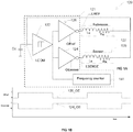
- FIGS. 1A/1B illustrate an example embodiment of an inductive sensor 120 with differential inductance readout based on sense/reference LC-ring oscillators with a shared capacitor.
- Differential sense (Lsense) and reference (Lref) resonators (LS/LR, Cc) are coupled to an inductance-to-data converter (IDC) including an IDC core 121.
- IDC inductance-to-data converter
- the Lsense/Lref resonators and IDC core 121 form dual, sense/reference LC-ring oscillators in which the Lsense/Lref resonators are time-multiplexed to enable resonator operation with a shared capacitor Cc.
- the Lsense and Lref resonators include LS and LR inductor coils, each coupled to common (shared) capacitor Cc, forming dual LC tank circuits.
- the resonator inductor coils are represented by an inductor element 125 that includes sense inductor coil LS and a loss factor represented by resistor RS, and an inductor element 127 that includes reference inductor coil LS and a loss factor represented by resistor RR.
- the resonator inductor coils can be referenced by either LS/LR, or 125/127.
- Using sense and reference inductor coils LS and LR eliminates temperature drift.
- accurate differential inductance readout requires matching the LS and LR sensor inputs (measurements).
- Using sense/reference LC-ring oscillators with time-multiplexed Lsense/Lref resonators enables resonator operation with a shared capacitor, eliminating the need for accurately matched separate resonator capacitors.
- LC-ring oscillators have a low noise floor, providing low phase jitter.
- IDC core 121 drives the Lsense/Lref resonators as LC-ring oscillators using a Schmitt trigger 122 and matched Lsense and Lref inverting drivers 124, 126.
- Schmitt trigger 122 has an input coupled to the Lsense/Lref resonators at an LCOM input port coupled to common (shared) capacitor Cc, and an output coupled to the Lsense/Lref drivers 124, 126.
- Drivers 124/126 are coupled to respective Lsense/Lref resonators through LSENSE and LREF output ports, coupled to the LS and LR inductor coils.
- Schmitt trigger 122 converts analog resonance measurements received from the Lsense/Lref resonators through the LCOM port, into digital Lsense/Lref resonator excitation signals.
- the matched Lsense/Lref inverting drivers 124, 126 drive the Lsense/Lref resonator excitation signals out of the LSENSE/LREF output ports to the resonators.
- Lsense/Lref drivers 124, 126 are enabled/disabled by out enable signals OEsense/OEref to time-multiplex the Lsense/Lref resonator excitation signals, thereby time-multiplexing the Lsense/Lref resonators for operation with the shared capacitor Cc (see FIG. 1B , 124_OE, 126_OE). That is, when the inductance of the LS sense inductor coil is measured (Lsense resonance measurement input to the Schmitt trigger), only OEsense is active to enable the Lsense driver 124, while OEref is low, disabling Lref driver 126 (high output impedance).
- Schmitt trigger 122 and the resonator capacitor Cc are shared.
- Mismatch between the Lsense/Lref drivers 124, 126 results in mismatch in propagation delay from Schmitt trigger input to the output, and mismatch in output impedance.
- Mismatch requirements for the delay can be relaxed under the condition that the delay is only a small fraction of the total oscillation period (for example, less than 2%).
- analog Schmitt trigger 122 in the ring oscillator core is a design choice to provide noise immunity.
- the analog Schmitt trigger can be eliminated.
- FIGS. 2A/2B illustrate, for the example inductive sensor of FIG. 1A , an example LC-ring oscillator operation for the Lsense (sense) resonator (LS, Cc).
- the sense-side LC-ring oscillator includes Schmitt trigger 122 and inverting driver 124.
- Schmitt trigger 122 receives Lsense resonance measurements 125osc from the Lsense resonator (Ls/Cc) through the LCOM port coupled to the shared capacitor Cc.
- the Schmitt trigger converts the Lsense resonance measurements 125osc to digital Lsense resonator excitation signals 122A.
- FIG. 2B illustrates the relationship between resonator oscillation frequency 125osc (across the shared capacitor Cc), and the high/low Schmitt trigger levels used to generate the digital Lsense resonator excitation signals 122A.
- differential inductance readout is based on LS and LR coil inductances, derived from the time-multiplexed Lsense/Lref resonance measurements for the Lsense/Lref resonators.
- IDC core 121 includes differential readout implemented as a differential frequency counter 141.
- Frequency counter 141 is coupled to receive the differential, time-multiplexed Schmitt trigger digital output ( FIG. 2B ).
- the Schmitt trigger digital output is based on the time-multiplexed Lsense/Lref resonance measurements input to Schmitt trigger 122.
- the frequency of the Schmitt trigger digital output depends on resonator oscillation frequency, which is a function of LS/LR coil inductance.
- LS/LR coil inductance can be used.
- sensor inductance can be measured as changes back emf caused by induced eddy currents
- sensor inductance can also be measured as changes in sensor losses resulting from induced eddy current losses, and changes in total sensor impedance based on changes in sensor inductance and loss factor.
- FIG. 3 illustrates, for the example embodiment of an inductive sensor 120 using sense/reference LC-ring oscillators, the effect of parasitic capacitance Cpar on the sense/reference drivers 124, 126, including introducing a second resonance mode.
- the time-multiplex phase is reading LS coil inductance (for the Lsense resonator), and hence the Lsense driver 124 is enabled to drive resonator excitation signals to the Lsense resonator.
- Lsense driver 124 has low output impedance, while the Lref driver is disabled, and has a high output impedance (which can be referred to as a high-Z).
- the Lsense resonator (LS Cc) is active, which is indicated by dashed line 125A through the LS inductor coil.
- the parasitic capacitance Cpar that is loading the enabled Lsense driver 124 has no impact on the resonator oscillation frequency, and therefore no impact on inductance readout, due to the low output impedance of this driver.
- dashed line 127A the parasitic capacitor Cpar loading the disabled Lref driver 126 (high-Z) adds a second resonant mode through the inactive LR inductor coil.
- the parasitic capacitor Cpar loading the disabled Lsense driver driving the Lsense resonator causes a second resonance mode through the inactive Ls inductor coil.
- the second resonance mode is undesirable, since it can interfere with desired resonance mode.
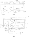
- FIGS. 4 and 5 illustrate alternate example embodiments of an inductive sensor 120, including modifications to the sense/reference LC-ring oscillators to minimize the second resonance mode caused by parasitic capacitance. To suppress the second resonant mode, these alternate embodiments prevent current flowing through the parasitic capacitor and inactive LS/LR inductor coil.
- FIG. 4 illustrates an example embodiment in which the LC-ring oscillators include shorting switches Ssense, Sref connected across the LS and LR inductor coils to selectively short the inactive LS/LR inductor coil. If a matched layout is used, both parasitic capacitors are matched as well, and the accuracy of the differential inductance measurement is not affected. For this implementation, the parasitic capacitance Cpar is added to the resonator capacitance Cc.
- FIG. 5 illustrates an example embodiment in which the LC-ring oscillators include shorting switches Ssense, Sref connected in series with respective bootstrap buffer amplifiers 535, 537, across the LS and LR inductor coils, to selectively bootstrap the common capacitor voltage across the disabled resonator.
- the bootstrap amplifiers can be as simple as a source follower or emitter follower. The advantage of this implementation is that any mismatch between the parasitic capacitors does not impact overall accuracy.
- FIGS. 6A and 6B illustrate example embodiments of inductive sensor systems 600 for inductive proximity switching according to example embodiments.
- An IDC 601 is coupled to sense/reference resonators, with LSENSE and LREF outputs respectively coupled to LS and LR inductor coils, and an LCOM input coupled to a common (shared) resonator capacitor Cc.
- IDC 601 provides proximity switching based on a difference (or ratio) of LS and LR coil inductance.
- a differential IDC core 621 includes sense and reference LC-ring oscillator converters incorporating the sense/reference resonators (sense/reference LS/LR inductor coils).
- Differential IDC core 621 provides differential inductance readout for input to a digital Schmitt trigger 651 (LS+ and LR-). As illustrated, the proximity switching response of the digital Schmitt trigger 651 is based on a difference (LS - LR) of LS and LR coil inductances provided as differential inductance readout from IDC core 621.
- the digital Schmitt trigger 651 can be configured to switch based on a differential inductance readout that is a ratio of the LS and LR coil inductances.
- differential inductance readout is a ratio of inductances LS/LR, such that, if LR is known, LS can be calculated, then the differential inductance ratio LS/LR, can be used directly for applications like weight scales, and for such implementations, the digital Schmitt trigger 651 is not required.
- example embodiments of an inductive sensing system include differential sense (Lsense) and reference (Lref) resonators with LS/LR sense/reference inductor coils, and a common capacitor Cc coupled to the LS and LR inductor coils.
- An inductance-to-data converter (IDC) is coupled to the Lsense/Lref resonators, through LSENSE/LREF output ports, coupled respectively to the LS/LR inductor coils, and through an LCOM input port to the common capacitor Cc.
- An Lsense driver with an output coupled through the LSENSE output to the LS inductor coil, and with an input coupled to the LCOM input, is selectively enabled by an out enable signal OEsense.
- An Lref driver with an output coupled through the LREF output to the LR inductor coil, and with an input coupled to the LCOM input, is selectively enabled by an out enable signal OEref.
- the OEsense and OEref signals are controlled to time-multiplex operation of the Lsense and Lref drivers.
- the Lsense driver and Lsense resonator are operable as an Lsense ring oscillator to drive, when enabled by the OEsense signal, time-multiplexed Lsense resonator excitation signals through the LSENSE output to the Lsense resonator, to maintain Lsense resonator oscillation, based on resulting time-multiplexed Lsense resonance measurements acquired from the Lsense resonator through the LCOM input.
- the Lref driver and the Lref resonator are operable as an Lref ring oscillator to drive, when enabled by the OEref signal, time-multiplexed Lref resonator excitation signals through the LREF output to the Lref resonator, to maintain Lref resonator oscillation, based on resulting time-multiplexed Lref resonance measurements acquired from the Lref resonator through the LCOM input.
- Readout circuitry provides differential readout data based on the time-multiplexed Lsense and Lref resonance measurements, corresponding respectively to the inductances of the LS and LR inductor coils.
- the Lsense resonance measurements can correspond to a resonance state of the Lsense resonator, including a resonance state with steady-state oscillation
- the Lref resonance measurements can correspond to a resonance state of the Lref resonator, including a resonance state with steady-state oscillation.
- Differential readout data can be based on Lsense and Lref resonator oscillation frequency, as related respectively to the inductances of the LS/LR inductor coils.
- the LC-ring oscillators can be implemented with a Schmitt trigger coupled to the LCOM input to convert time-multiplexed Lsense/Lref resonance measurements from the Lsense/Lref resonators, to digital Schmitt trigger output based on predetermined high and low thresholds, with the Lsense/Lref drivers coupled to receive the Schmitt trigger output.
- the Lsense/Lref drivers can be fabricated with matched circuitry to provide matched output impedance, and layout matching can be used for the Lsense/Lref drivers to match respective parasitic capacitances at the outputs of the Lsense/Lref drivers.
- parasitic capacitances at the Lsense/Lref driver outputs can be suppressed by either: (a) Ssense/Sref shorting switches connected across respectively the LS/LR inductor coils, and operable to selectively short the inactive inductor coil; or (b) Ssense/Sref shorting switches connected in series with respective bootstrap buffer amplifiers, across respectively the LS/LR inductor coils, the Ssense/Sref switches operable to selectively bootstrap a voltage from the common capacitor Cc across the inactive inductor coil.
Landscapes
- Physics & Mathematics (AREA)
- General Physics & Mathematics (AREA)
- Life Sciences & Earth Sciences (AREA)
- Engineering & Computer Science (AREA)
- Remote Sensing (AREA)
- Environmental & Geological Engineering (AREA)
- Electromagnetism (AREA)
- Geology (AREA)
- General Life Sciences & Earth Sciences (AREA)
- Geophysics (AREA)
- Inductance-Capacitance Distribution Constants And Capacitance-Resistance Oscillators (AREA)
- Electronic Switches (AREA)
- Measuring Magnetic Variables (AREA)
Claims (16)
- Integrierte Induktivität-zu-Daten-Umsetzer-Schaltung, d. h. integrierte IDC-Schaltung, die für einen Betrieb mit einem externen Erfassungs- und einem externen Referenzresonator, Lsense bzw. Lref, geeignet ist, wobei der Lsense- und der Lref-Resonator jeweils eine Erfassungsinduktionsspule, LS, und eine Referenzinduktionsspule, LR, enthalten, und einen gemeinsamen Resonatorkondensator, Cc, enthalten, wobei die IDC-Schaltung Folgendes umfasst:einen LSENSE-Ausgang zum Koppeln an die LS-Induktionsspule;einen LREF-Ausgang zum Koppeln an die LR-Induktionsspule;einen LCOM-Eingang zum Koppeln an den Resonatorkondensator, Cc;eine Lsense-Ansteuerung mit einem Ausgang, der an den LSENSE-Ausgang gekoppelt ist, und einem Eingang, der an den LCOM-Eingang gekoppelt ist, wobei die Lsense-Ansteuerung wahlweise durch ein Aus-Aktivierungssignal, OEsense, aktiviert wird;eine Lref-Ansteuerung mit einem Ausgang, der an den LREF-Ausgang gekoppelt ist, und einem Eingang, der an den LCOM-Eingang gekoppelt ist, wobei die Lref-Ansteuerung wahlweise durch ein Aus-Aktivierungssignal, OEref, aktiviert wird;wobei das OEsense- und das OEref-Signal durch einen Zeitmultiplex-Betrieb der Lsense- und der Lref-Ansteuerung gesteuert werden;wobei die Lsense-Ansteuerung mit dem Lsense-Resonator als einem Lsense-Ringoszillator dann, wenn sie durch das OEsense-Signal aktiviert wird, betreibbar ist, zeitmultiplexierte Lsense-Resonatoranregungssignale durch den LSENSE-Ausgang anhand von zeitmultiplexierten Lsense-Resonatormessungen, die von dem LCOM-Eingang empfangen werden, zu lenken;wobei die Lref-Ansteuerung mit dem Lref-Resonator als einem Lref-Ringoszillator dann, wenn sie durch das OEref-Signal aktiviert wird, betreibbar ist, zeitmultiplexierte Lres-Resonator-Anregungssignale durch den LREF-Ausgang anhand von zeitmultiplexierten Lref-Resonanzmessungen, die von dem LCOM-Eingang empfangen werden, zu lenken; undeine Ausleseschaltung, um differenzielle Auslesedaten anhand der zeitmultiplexierten Lsense- und Lref-Resonanzmessungen zu liefern, die jeweils Induktivitäten der LS- und der LR-Induktionsspule entsprechen.
- Integrierte Schaltung nach Anspruch 1, wobei:der LSENSE-Ausgang an die externe LS-Induktionsspule gekoppelt ist;der LREF-Ausgang an die externe LR-Induktionsspule gekoppelt ist;der LCOM-Eingang an den gemeinsamen Resonatorkondensator gekoppelt ist;die zeitmultiplexierten Lsense-Resonatoranregungssignale durch den LENSE-Ausgang zu dem Lsense-Resonator gelenkt werden, um eine Lsense-Resonatorschwingung aufrechtzuerhalten; unddie zeitmultiplexierten Lref-Resonatoranregungssignale durch den LREF-Ausgang zu dem Lref-Resonator gelenkt werden, um die Lref-Resonatorschwingung aufrechtzuerhalten.
- Integrierte Schaltung nach Anspruch 1, die ferner Folgendes umfasst:
einen Schmitt-Trigger, der an den LCOM-Eingang gekoppelt ist, um die zeitmultiplexierten Lsense- und Lref-Resonanzmessungen von dem Lsense- und dem Lref-Resonator anhand eines vorbestimmte hohen und niedrigen Schwellenwerts, die an die Lsense- und die Lref-Ansteuerung geliefert werden, in einen digitalen Schmitt-Trigger-Ausgang umzusetzen. - Induktives Erfassungssystem, das Folgendes umfasst:einen differenziellen Erfassungs- und einen differenziellen Referenzresonator, Lsense bzw. Lref, die Folgendes enthalten: eine Erfassungsinduktionsspule, LS; eine Referenzinduktionsspule, LR; und einen gemeinsamen Kondensator, Cc, der an die LS- und die LR-Induktionsspule gekoppelt ist,wobei die IDC nach Anspruch 1 durch einen LSENSE- und einen LREF-Ausgang, die jeweils an die LS- und die LR-Induktionsspule gekoppelt sind, und durch einen LCOM-Eingang, der an den gemeinsamen Kondensator, Cc, gekoppelt ist, an den Lsense- und den Lref-Resonator gekoppelt ist.
- Integrierte Schaltung nach Anspruch 2 oder System nach Anspruch 4, wobei:die Lsense-Resonanzmessungen einem Resonanzzustand des Lsense-Resonators entsprechen, einschließlich eines Resonanzzustands mit einer Schwingung eines stabilen Zustands; unddie Lref-Resonanzmessungen einem Resonanzzustand des Lref-Resonators entsprechen, einschließlich eines Resonanzzustands mit einer Schwingung eines stabilen Zustands.
- Integrierte Schaltung nach Anspruch 1 oder das System nach Anspruch 4, wobei die Ausleseschaltung differenzielle Auslesedaten anhand der Lsense- und der Lref-Resonatorschwingungsfrequenz liefert, wie jeweils auf die Induktivitäten der LS- und LR-Induktionsspule bezogen.
- System nach Anspruch 4, wobei die LC-Ring- Oszillatoren mit einem Schmitt-Trigger implementiert sind, der an den LCOM-Eingang gekoppelt ist, um die zeitmultiplexierten Lsense- und Lref-Resonanzmessungen von dem Lsense- und dem Lref-Resonator anhand eines vorbestimmten hohen und niedrigen Schwellenwerts, die an die Lsense- und die Lref-Ansteuerung geliefert werden, zu einem digitalen Schmitt-Triggerausgang umzusetzen.
- Integrierte Schaltung nach Anspruch 1 oder System nach Anspruch 4, wobei:die Lsense- und die Lref-Ansteuerung mit angepasster Schaltung hergestellt werden, um eine angepasste Ausgangsimpedanz zu liefern; undeine Layoutanpassung für die Lsense- und die Lref-Ansteuerung verwendet wird, um jeweilige parasitäre Kapazitäten an den Ausgängen der Lsense- und der Lref-Ansteuerung anzupassen.
- Integrierte Schaltung nach Anspruch 2 oder System nach Anspruch 4, das ferner eines des Folgenden umfasst:einen Ssense- und einen Sref-Kurschlussschalter, die jeweils über die LS- und die LR-Induktionsspule angeschlossen sind und betreibbar sind, wahlweise eine inaktive der Induktionsspulen kurzzuschließen; undeinen Ssense- und einen Sref-Kurzschlussschalter, die in Reihe mit jeweiligen Bootstrap-Pufferverstärkern jeweils über die LS- und die LR-Induktionsspule angeschlossen sind, wobei der Ssense- und der Sref-Schalter betreibbar sind, wahlweise eine Spannung von dem gemeinsamen Kondensator, Cc, über eine inaktive der Induktionsspulen urzuladen.
- Integrierte Schaltung nach Anspruch 2 oder System nach Anspruch 4 für die Verwendung als ein induktiver Schalter, wobei:die LS-Induktionsspule angeordnet ist, um die Nähe eines leitenden Ziels zu detektieren; unddie Ausleseschaltung differenzielle Auslesedaten liefert, die einem Näheereignis entsprechen, in dem sich das Ziel in einer vordefinierten Nähe zu der LS-Induktionsspule befindet.
- Verfahren zum induktiven Erfassen, das für die Verwendung mit einem Erfassungs- und einem Referenzresonator, Lsense und Lref, geeignet ist, wobei der Lsense- und der Lref-Resonator jeweils eine Erfassungsinduktionsspule, LS, und eine Referenzinduktionsspule LR, enthalten, und einen gemeinsamen Resonanzkondensator, Cc, enthalten, das Folgendes umfasst:Ansteuern des Lsense-Resonators als einen zeitmultiplexierten Lsense-Ringoszillator, das enthält, zeitmultiplexierte Lsense-Resonatoranregungssignale in den Lsense-Resonator zu lenken, um eine Lsense-Resonator-Schwingung aufrechtzuerhalten, anhand sich ergebender zeitmultiplexierter Lsense-Resonanzmessungen, die in den Lsense-Ringoszillator von dem Lsense-Resonator eingegeben werden;Ansteuern des Lref-Resonators als einen zeitmultiplexierten Lref-Ringoszillator, das enthält, zeitmultiplexierte Lref-Resonatoranregungssignale in den Lref-Resonator zu lenken, um eine Lsense-Resonatorsschwingung aufrechtzuerhalten, anhand sich ergebender zeitmultiplexierter Lref-Resonatormessungen, die in den Lref-Ringoszillator von dem Lref-Resonator eingegeben werden;Zeitpultiplexen des Betriebs des Lsense- und des Lref-Ringoszillators, um zu ermöglichen, den gemeinsamen Resonatorkondensator, Cc, durch den Lsense- und den Lref-resonator gemeinsam zu nutzen; undLiefern differenzieller Auslesedaten anhand der zeitmultiplexierten Lsense- und Lref-Resonanzmessungen, die jeweils Induktivitäten der Ls- und der LR-Induktionsspule entsprechen.
- Verfahren nach Anspruch 11, wobei:die Lsense-Resonanzmessungen einem Resonanzzustand des Lsense-Resonators entsprechen, einschließlich eines Resonanzzustands mit Schwingung eines stabilen Zustands; unddie Lref-Resonanzmessungen einem Resonanzzustand des Lref-Resonators entsprechen, einschließlich eines Resonanzzustands mit Schwingung eines stabilen Zustands.
- Verfahren nach Anspruch 11, wobei die differenziellen Auslesedaten auf einer Lsense- und einer Lref-Resonatorschwingungsfrequenz beruhen, wie jeweils auf die Induktivitäten der LS- und der LR-Induktionsspule bezogen.
- Verfahren nach Anspruch 11, wobei die LC-Ringoszillatoren mit einem Schmitt-Trigger implementiert sind, der an den LCOM-Eingang gekoppelt ist, um die zeitmultiplexierten Lsense- und Lref-Resonanzmessungen von dem Lsense- und dem Lref-Resonator in einen digitalen Schmitt-Trigger-Ausgang umzusetzen, anhand eines vorbestimmten hohen und niedrigen Schwellenwerts, die an die Lsense- und die Lref-Ansteuerung geliefert werden.
- Verfahren nach Anspruch 11, das ferner eines der Folgenden umfasst:wahlweise Kurzschließen einer inaktiven der Induktionsspulen; undwahlweise Urladen einer Spannung von dem gemeinsamen Resonatorkondensator, Cc, über eine inaktive der Induktionsspulen.
- Verfahren nach Anspruch 11 für die Verwendung in einer induktiven Schaltung, wobei:die LS-Induktionsspule angeordnet ist, um die Nähe eines leitenden Ziels zu detektieren; unddie differenziellen Auslesedaten einem Näheereignis entsprechen, in dem sich das Ziel in einer vordefinierten Nähe zu der LS-Induktionsspule befindet.
Applications Claiming Priority (2)
| Application Number | Priority Date | Filing Date | Title |
|---|---|---|---|
| US201562213252P | 2015-09-02 | 2015-09-02 | |
| PCT/US2016/050238 WO2017041019A1 (en) | 2015-09-02 | 2016-09-02 | Inductive sensing with differential inductance readout based on sense/reference lc-ring oscillators with a shared capacitor |
Publications (3)
| Publication Number | Publication Date |
|---|---|
| EP3345007A1 EP3345007A1 (de) | 2018-07-11 |
| EP3345007A4 EP3345007A4 (de) | 2018-12-19 |
| EP3345007B1 true EP3345007B1 (de) | 2019-11-13 |
Family
ID=58103988
Family Applications (1)
| Application Number | Title | Priority Date | Filing Date |
|---|---|---|---|
| EP16843125.2A Active EP3345007B1 (de) | 2015-09-02 | 2016-09-02 | Induktive messung mit ablesung der differenziellen induktivität auf der basis von sensor-/referenz-lc-ringoszillatoren mit gemeinsamem kondensator |
Country Status (4)
| Country | Link |
|---|---|
| US (1) | US10295694B2 (de) |
| EP (1) | EP3345007B1 (de) |
| CN (1) | CN107923930B (de) |
| WO (1) | WO2017041019A1 (de) |
Families Citing this family (2)
| Publication number | Priority date | Publication date | Assignee | Title |
|---|---|---|---|---|
| US11340064B2 (en) * | 2017-04-10 | 2022-05-24 | Texas Instruments Incorporated | Tilt switch based on differential sensing |
| CN121602983B (zh) * | 2026-01-29 | 2026-04-10 | 无锡中微爱芯电子有限公司 | 一种应用于fpc柔性电路板的圆盘式滑轮触摸检测方法 |
Family Cites Families (12)
| Publication number | Priority date | Publication date | Assignee | Title |
|---|---|---|---|---|
| JPS5928012B2 (ja) * | 1979-06-18 | 1984-07-10 | オムロン株式会社 | 近接スイッチ |
| CH672383A5 (de) * | 1986-10-29 | 1989-11-15 | Baumer Electric Ag | |
| DE3840532A1 (de) | 1988-12-01 | 1990-06-07 | Pepperl & Fuchs | Verfahren zur induktiven erzeugung eines elektrischen messsignals zur bestimmung des weges und/oder der position im raum und/oder von materialeigenschaften eines pruefkoerpers und nach diesem verfahren aufgebauter naeherungssensor und verwendung desselben als naeherherungsschalter |
| US7772839B2 (en) * | 2003-09-19 | 2010-08-10 | Tk Holdings, Inc. | Eddy current magnetic crash sensor |
| US7292026B2 (en) | 2005-04-08 | 2007-11-06 | Ksr International Co. | Signal conditioning system for inductive position sensor |
| JP2009545356A (ja) * | 2006-08-02 | 2009-12-24 | コーニンクレッカ フィリップス エレクトロニクス エヌ ヴィ | 患者の動脈系からパルス波の通過を検出するセンサー |
| US7808235B2 (en) * | 2007-11-29 | 2010-10-05 | Rockwell Automation Technologies, Inc. | Apparatus and methods for proximity sensing circuitry |
| US9176206B2 (en) | 2008-03-07 | 2015-11-03 | California Institute Of Technology | Effective-inductance-change based magnetic particle sensing |
| JP5490482B2 (ja) * | 2009-10-09 | 2014-05-14 | ピーエスフォー ルクスコ エスエイアールエル | 半導体装置 |
| CN102003973B (zh) * | 2010-10-19 | 2013-01-23 | 首都医科大学 | 一种无线无源的测量方法与电路 |
| US9479134B2 (en) * | 2013-03-04 | 2016-10-25 | Texas Instruments Incorporated | Position detecting system |
| GB2517152A (en) * | 2013-08-12 | 2015-02-18 | Gde Technology Ltd | Position sensor |
-
2016
- 2016-09-02 EP EP16843125.2A patent/EP3345007B1/de active Active
- 2016-09-02 US US15/255,145 patent/US10295694B2/en active Active
- 2016-09-02 WO PCT/US2016/050238 patent/WO2017041019A1/en not_active Ceased
- 2016-09-02 CN CN201680045259.5A patent/CN107923930B/zh active Active
Non-Patent Citations (1)
| Title |
|---|
| None * |
Also Published As
| Publication number | Publication date |
|---|---|
| US10295694B2 (en) | 2019-05-21 |
| US20170059735A1 (en) | 2017-03-02 |
| CN107923930B (zh) | 2020-07-10 |
| WO2017041019A1 (en) | 2017-03-09 |
| EP3345007A1 (de) | 2018-07-11 |
| EP3345007A4 (de) | 2018-12-19 |
| CN107923930A (zh) | 2018-04-17 |
Similar Documents
| Publication | Publication Date | Title |
|---|---|---|
| JP6515107B2 (ja) | 複数の共振センサに対する単一チャネルインタフェースを備えた誘導性位置感知 | |
| JP5389389B2 (ja) | 線間電圧測定装置およびプログラム | |
| US7576533B2 (en) | Inductive angular-position sensor | |
| CN101387709A (zh) | 具有被切换的线圈的感应式临近检测器 | |
| NL8701980A (nl) | Inductieve naderingssensor. | |
| WO1991018299A1 (en) | Device for sensing magnetism | |
| JP2008020270A (ja) | 電圧測定装置 | |
| JP2007163414A (ja) | 可変容量回路、電圧測定装置および電力測定装置 | |
| US11143681B2 (en) | Method and device for determining a sensor coil inductance | |
| CN106403792A (zh) | 基于反射导纳进行距离确定 | |
| JP2007195137A (ja) | 可変容量回路、電圧測定装置および電力測定装置 | |
| KR20140052827A (ko) | 임피던스 소스 레인징 장치 및 방법 | |
| JP2008014645A (ja) | 電圧測定装置 | |
| US10295694B2 (en) | Inductive sensing with differential inductance readout | |
| CN114112092A (zh) | 一种传感器环境温度测量电路及传感器 | |
| US11268832B2 (en) | Coil assembly and corresponding measuring assembly | |
| US9372217B2 (en) | Cable detector | |
| CN101788611A (zh) | 电阻率测量装置及方法 | |
| US20140002069A1 (en) | Eddy current probe | |
| CN218781916U (zh) | 一种传感器环境温度测量电路及传感器 | |
| US11112439B2 (en) | Evaluating circuit, system, and method for evaluating a capacitive or inductive sensor | |
| JP2019144222A (ja) | 磁気センサ | |
| JP5106816B2 (ja) | 電圧測定装置および電力測定装置 | |
| JP3701510B2 (ja) | トナー濃度センサ | |
| US12123754B2 (en) | Magnetic-inductive flowmeter and method of operating the same |
Legal Events
| Date | Code | Title | Description |
|---|---|---|---|
| STAA | Information on the status of an ep patent application or granted ep patent |
Free format text: STATUS: THE INTERNATIONAL PUBLICATION HAS BEEN MADE |
|
| PUAI | Public reference made under article 153(3) epc to a published international application that has entered the european phase |
Free format text: ORIGINAL CODE: 0009012 |
|
| STAA | Information on the status of an ep patent application or granted ep patent |
Free format text: STATUS: REQUEST FOR EXAMINATION WAS MADE |
|
| 17P | Request for examination filed |
Effective date: 20180403 |
|
| AK | Designated contracting states |
Kind code of ref document: A1 Designated state(s): AL AT BE BG CH CY CZ DE DK EE ES FI FR GB GR HR HU IE IS IT LI LT LU LV MC MK MT NL NO PL PT RO RS SE SI SK SM TR |
|
| AX | Request for extension of the european patent |
Extension state: BA ME |
|
| REG | Reference to a national code |
Ref country code: DE Ref legal event code: R079 Ref document number: 602016024468 Country of ref document: DE Free format text: PREVIOUS MAIN CLASS: G01R0015180000 Ipc: G01D0005220000 |
|
| DAV | Request for validation of the european patent (deleted) | ||
| DAX | Request for extension of the european patent (deleted) | ||
| A4 | Supplementary search report drawn up and despatched |
Effective date: 20181115 |
|
| RIC1 | Information provided on ipc code assigned before grant |
Ipc: G01D 5/22 20060101AFI20181109BHEP Ipc: G01V 3/10 20060101ALI20181109BHEP Ipc: G01D 5/243 20060101ALI20181109BHEP |
|
| GRAP | Despatch of communication of intention to grant a patent |
Free format text: ORIGINAL CODE: EPIDOSNIGR1 |
|
| STAA | Information on the status of an ep patent application or granted ep patent |
Free format text: STATUS: GRANT OF PATENT IS INTENDED |
|
| INTG | Intention to grant announced |
Effective date: 20190726 |
|
| GRAS | Grant fee paid |
Free format text: ORIGINAL CODE: EPIDOSNIGR3 |
|
| GRAA | (expected) grant |
Free format text: ORIGINAL CODE: 0009210 |
|
| STAA | Information on the status of an ep patent application or granted ep patent |
Free format text: STATUS: THE PATENT HAS BEEN GRANTED |
|
| AK | Designated contracting states |
Kind code of ref document: B1 Designated state(s): AL AT BE BG CH CY CZ DE DK EE ES FI FR GB GR HR HU IE IS IT LI LT LU LV MC MK MT NL NO PL PT RO RS SE SI SK SM TR |
|
| REG | Reference to a national code |
Ref country code: CH Ref legal event code: EP Ref country code: AT Ref legal event code: REF Ref document number: 1202149 Country of ref document: AT Kind code of ref document: T Effective date: 20191115 |
|
| REG | Reference to a national code |
Ref country code: DE Ref legal event code: R096 Ref document number: 602016024468 Country of ref document: DE |
|
| REG | Reference to a national code |
Ref country code: IE Ref legal event code: FG4D |
|
| REG | Reference to a national code |
Ref country code: NL Ref legal event code: MP Effective date: 20191113 |
|
| REG | Reference to a national code |
Ref country code: LT Ref legal event code: MG4D |
|
| PG25 | Lapsed in a contracting state [announced via postgrant information from national office to epo] |
Ref country code: NL Free format text: LAPSE BECAUSE OF FAILURE TO SUBMIT A TRANSLATION OF THE DESCRIPTION OR TO PAY THE FEE WITHIN THE PRESCRIBED TIME-LIMIT Effective date: 20191113 Ref country code: SE Free format text: LAPSE BECAUSE OF FAILURE TO SUBMIT A TRANSLATION OF THE DESCRIPTION OR TO PAY THE FEE WITHIN THE PRESCRIBED TIME-LIMIT Effective date: 20191113 Ref country code: LV Free format text: LAPSE BECAUSE OF FAILURE TO SUBMIT A TRANSLATION OF THE DESCRIPTION OR TO PAY THE FEE WITHIN THE PRESCRIBED TIME-LIMIT Effective date: 20191113 Ref country code: PL Free format text: LAPSE BECAUSE OF FAILURE TO SUBMIT A TRANSLATION OF THE DESCRIPTION OR TO PAY THE FEE WITHIN THE PRESCRIBED TIME-LIMIT Effective date: 20191113 Ref country code: GR Free format text: LAPSE BECAUSE OF FAILURE TO SUBMIT A TRANSLATION OF THE DESCRIPTION OR TO PAY THE FEE WITHIN THE PRESCRIBED TIME-LIMIT Effective date: 20200214 Ref country code: PT Free format text: LAPSE BECAUSE OF FAILURE TO SUBMIT A TRANSLATION OF THE DESCRIPTION OR TO PAY THE FEE WITHIN THE PRESCRIBED TIME-LIMIT Effective date: 20200313 Ref country code: BG Free format text: LAPSE BECAUSE OF FAILURE TO SUBMIT A TRANSLATION OF THE DESCRIPTION OR TO PAY THE FEE WITHIN THE PRESCRIBED TIME-LIMIT Effective date: 20200213 Ref country code: NO Free format text: LAPSE BECAUSE OF FAILURE TO SUBMIT A TRANSLATION OF THE DESCRIPTION OR TO PAY THE FEE WITHIN THE PRESCRIBED TIME-LIMIT Effective date: 20200213 Ref country code: FI Free format text: LAPSE BECAUSE OF FAILURE TO SUBMIT A TRANSLATION OF THE DESCRIPTION OR TO PAY THE FEE WITHIN THE PRESCRIBED TIME-LIMIT Effective date: 20191113 Ref country code: LT Free format text: LAPSE BECAUSE OF FAILURE TO SUBMIT A TRANSLATION OF THE DESCRIPTION OR TO PAY THE FEE WITHIN THE PRESCRIBED TIME-LIMIT Effective date: 20191113 |
|
| PG25 | Lapsed in a contracting state [announced via postgrant information from national office to epo] |
Ref country code: HR Free format text: LAPSE BECAUSE OF FAILURE TO SUBMIT A TRANSLATION OF THE DESCRIPTION OR TO PAY THE FEE WITHIN THE PRESCRIBED TIME-LIMIT Effective date: 20191113 Ref country code: IS Free format text: LAPSE BECAUSE OF FAILURE TO SUBMIT A TRANSLATION OF THE DESCRIPTION OR TO PAY THE FEE WITHIN THE PRESCRIBED TIME-LIMIT Effective date: 20200313 Ref country code: RS Free format text: LAPSE BECAUSE OF FAILURE TO SUBMIT A TRANSLATION OF THE DESCRIPTION OR TO PAY THE FEE WITHIN THE PRESCRIBED TIME-LIMIT Effective date: 20191113 |
|
| PG25 | Lapsed in a contracting state [announced via postgrant information from national office to epo] |
Ref country code: AL Free format text: LAPSE BECAUSE OF FAILURE TO SUBMIT A TRANSLATION OF THE DESCRIPTION OR TO PAY THE FEE WITHIN THE PRESCRIBED TIME-LIMIT Effective date: 20191113 |
|
| PG25 | Lapsed in a contracting state [announced via postgrant information from national office to epo] |
Ref country code: CZ Free format text: LAPSE BECAUSE OF FAILURE TO SUBMIT A TRANSLATION OF THE DESCRIPTION OR TO PAY THE FEE WITHIN THE PRESCRIBED TIME-LIMIT Effective date: 20191113 Ref country code: ES Free format text: LAPSE BECAUSE OF FAILURE TO SUBMIT A TRANSLATION OF THE DESCRIPTION OR TO PAY THE FEE WITHIN THE PRESCRIBED TIME-LIMIT Effective date: 20191113 Ref country code: RO Free format text: LAPSE BECAUSE OF FAILURE TO SUBMIT A TRANSLATION OF THE DESCRIPTION OR TO PAY THE FEE WITHIN THE PRESCRIBED TIME-LIMIT Effective date: 20191113 Ref country code: EE Free format text: LAPSE BECAUSE OF FAILURE TO SUBMIT A TRANSLATION OF THE DESCRIPTION OR TO PAY THE FEE WITHIN THE PRESCRIBED TIME-LIMIT Effective date: 20191113 Ref country code: DK Free format text: LAPSE BECAUSE OF FAILURE TO SUBMIT A TRANSLATION OF THE DESCRIPTION OR TO PAY THE FEE WITHIN THE PRESCRIBED TIME-LIMIT Effective date: 20191113 |
|
| REG | Reference to a national code |
Ref country code: DE Ref legal event code: R097 Ref document number: 602016024468 Country of ref document: DE |
|
| REG | Reference to a national code |
Ref country code: AT Ref legal event code: MK05 Ref document number: 1202149 Country of ref document: AT Kind code of ref document: T Effective date: 20191113 |
|
| PG25 | Lapsed in a contracting state [announced via postgrant information from national office to epo] |
Ref country code: SM Free format text: LAPSE BECAUSE OF FAILURE TO SUBMIT A TRANSLATION OF THE DESCRIPTION OR TO PAY THE FEE WITHIN THE PRESCRIBED TIME-LIMIT Effective date: 20191113 Ref country code: SK Free format text: LAPSE BECAUSE OF FAILURE TO SUBMIT A TRANSLATION OF THE DESCRIPTION OR TO PAY THE FEE WITHIN THE PRESCRIBED TIME-LIMIT Effective date: 20191113 |
|
| PLBE | No opposition filed within time limit |
Free format text: ORIGINAL CODE: 0009261 |
|
| STAA | Information on the status of an ep patent application or granted ep patent |
Free format text: STATUS: NO OPPOSITION FILED WITHIN TIME LIMIT |
|
| 26N | No opposition filed |
Effective date: 20200814 |
|
| PG25 | Lapsed in a contracting state [announced via postgrant information from national office to epo] |
Ref country code: AT Free format text: LAPSE BECAUSE OF FAILURE TO SUBMIT A TRANSLATION OF THE DESCRIPTION OR TO PAY THE FEE WITHIN THE PRESCRIBED TIME-LIMIT Effective date: 20191113 Ref country code: SI Free format text: LAPSE BECAUSE OF FAILURE TO SUBMIT A TRANSLATION OF THE DESCRIPTION OR TO PAY THE FEE WITHIN THE PRESCRIBED TIME-LIMIT Effective date: 20191113 |
|
| PG25 | Lapsed in a contracting state [announced via postgrant information from national office to epo] |
Ref country code: IT Free format text: LAPSE BECAUSE OF FAILURE TO SUBMIT A TRANSLATION OF THE DESCRIPTION OR TO PAY THE FEE WITHIN THE PRESCRIBED TIME-LIMIT Effective date: 20191113 |
|
| REG | Reference to a national code |
Ref country code: CH Ref legal event code: PL |
|
| REG | Reference to a national code |
Ref country code: BE Ref legal event code: MM Effective date: 20200930 |
|
| PG25 | Lapsed in a contracting state [announced via postgrant information from national office to epo] |
Ref country code: LU Free format text: LAPSE BECAUSE OF NON-PAYMENT OF DUE FEES Effective date: 20200902 |
|
| PG25 | Lapsed in a contracting state [announced via postgrant information from national office to epo] |
Ref country code: LI Free format text: LAPSE BECAUSE OF NON-PAYMENT OF DUE FEES Effective date: 20200930 Ref country code: IE Free format text: LAPSE BECAUSE OF NON-PAYMENT OF DUE FEES Effective date: 20200902 Ref country code: CH Free format text: LAPSE BECAUSE OF NON-PAYMENT OF DUE FEES Effective date: 20200930 Ref country code: BE Free format text: LAPSE BECAUSE OF NON-PAYMENT OF DUE FEES Effective date: 20200930 |
|
| PG25 | Lapsed in a contracting state [announced via postgrant information from national office to epo] |
Ref country code: TR Free format text: LAPSE BECAUSE OF FAILURE TO SUBMIT A TRANSLATION OF THE DESCRIPTION OR TO PAY THE FEE WITHIN THE PRESCRIBED TIME-LIMIT Effective date: 20191113 Ref country code: MT Free format text: LAPSE BECAUSE OF FAILURE TO SUBMIT A TRANSLATION OF THE DESCRIPTION OR TO PAY THE FEE WITHIN THE PRESCRIBED TIME-LIMIT Effective date: 20191113 Ref country code: CY Free format text: LAPSE BECAUSE OF FAILURE TO SUBMIT A TRANSLATION OF THE DESCRIPTION OR TO PAY THE FEE WITHIN THE PRESCRIBED TIME-LIMIT Effective date: 20191113 |
|
| PG25 | Lapsed in a contracting state [announced via postgrant information from national office to epo] |
Ref country code: MK Free format text: LAPSE BECAUSE OF FAILURE TO SUBMIT A TRANSLATION OF THE DESCRIPTION OR TO PAY THE FEE WITHIN THE PRESCRIBED TIME-LIMIT Effective date: 20191113 Ref country code: MC Free format text: LAPSE BECAUSE OF FAILURE TO SUBMIT A TRANSLATION OF THE DESCRIPTION OR TO PAY THE FEE WITHIN THE PRESCRIBED TIME-LIMIT Effective date: 20191113 |
|
| P01 | Opt-out of the competence of the unified patent court (upc) registered |
Effective date: 20230523 |
|
| PGFP | Annual fee paid to national office [announced via postgrant information from national office to epo] |
Ref country code: DE Payment date: 20250820 Year of fee payment: 10 |
|
| PGFP | Annual fee paid to national office [announced via postgrant information from national office to epo] |
Ref country code: GB Payment date: 20250820 Year of fee payment: 10 |
|
| PGFP | Annual fee paid to national office [announced via postgrant information from national office to epo] |
Ref country code: FR Payment date: 20250821 Year of fee payment: 10 |