EP3344387B1 - Clean chamber technology for 3d printers and bioprinters - Google Patents
Clean chamber technology for 3d printers and bioprinters Download PDFInfo
- Publication number
- EP3344387B1 EP3344387B1 EP16842913.2A EP16842913A EP3344387B1 EP 3344387 B1 EP3344387 B1 EP 3344387B1 EP 16842913 A EP16842913 A EP 16842913A EP 3344387 B1 EP3344387 B1 EP 3344387B1
- Authority
- EP
- European Patent Office
- Prior art keywords
- housing
- printer
- air
- supply unit
- air supply
- Prior art date
- Legal status (The legal status is an assumption and is not a legal conclusion. Google has not performed a legal analysis and makes no representation as to the accuracy of the status listed.)
- Active
Links
Images



Classifications
-
- B—PERFORMING OPERATIONS; TRANSPORTING
- B29—WORKING OF PLASTICS; WORKING OF SUBSTANCES IN A PLASTIC STATE IN GENERAL
- B29C—SHAPING OR JOINING OF PLASTICS; SHAPING OF MATERIAL IN A PLASTIC STATE, NOT OTHERWISE PROVIDED FOR; AFTER-TREATMENT OF THE SHAPED PRODUCTS, e.g. REPAIRING
- B29C64/00—Additive manufacturing, i.e. manufacturing of three-dimensional [3D] objects by additive deposition, additive agglomeration or additive layering, e.g. by 3D printing, stereolithography or selective laser sintering
- B29C64/30—Auxiliary operations or equipment
- B29C64/364—Conditioning of environment
-
- B—PERFORMING OPERATIONS; TRANSPORTING
- B01—PHYSICAL OR CHEMICAL PROCESSES OR APPARATUS IN GENERAL
- B01L—CHEMICAL OR PHYSICAL LABORATORY APPARATUS FOR GENERAL USE
- B01L1/00—Enclosures; Chambers
- B01L1/02—Air-pressure chambers; Air-locks therefor
-
- B—PERFORMING OPERATIONS; TRANSPORTING
- B01—PHYSICAL OR CHEMICAL PROCESSES OR APPARATUS IN GENERAL
- B01L—CHEMICAL OR PHYSICAL LABORATORY APPARATUS FOR GENERAL USE
- B01L3/00—Containers or dishes for laboratory use, e.g. laboratory glassware; Droppers
- B01L3/02—Burettes; Pipettes
- B01L3/0241—Drop counters; Drop formers
-
- B—PERFORMING OPERATIONS; TRANSPORTING
- B29—WORKING OF PLASTICS; WORKING OF SUBSTANCES IN A PLASTIC STATE IN GENERAL
- B29C—SHAPING OR JOINING OF PLASTICS; SHAPING OF MATERIAL IN A PLASTIC STATE, NOT OTHERWISE PROVIDED FOR; AFTER-TREATMENT OF THE SHAPED PRODUCTS, e.g. REPAIRING
- B29C64/00—Additive manufacturing, i.e. manufacturing of three-dimensional [3D] objects by additive deposition, additive agglomeration or additive layering, e.g. by 3D printing, stereolithography or selective laser sintering
- B29C64/20—Apparatus for additive manufacturing; Details thereof or accessories therefor
- B29C64/245—Platforms or substrates
-
- B—PERFORMING OPERATIONS; TRANSPORTING
- B29—WORKING OF PLASTICS; WORKING OF SUBSTANCES IN A PLASTIC STATE IN GENERAL
- B29C—SHAPING OR JOINING OF PLASTICS; SHAPING OF MATERIAL IN A PLASTIC STATE, NOT OTHERWISE PROVIDED FOR; AFTER-TREATMENT OF THE SHAPED PRODUCTS, e.g. REPAIRING
- B29C64/00—Additive manufacturing, i.e. manufacturing of three-dimensional [3D] objects by additive deposition, additive agglomeration or additive layering, e.g. by 3D printing, stereolithography or selective laser sintering
- B29C64/20—Apparatus for additive manufacturing; Details thereof or accessories therefor
- B29C64/25—Housings, e.g. machine housings
-
- B—PERFORMING OPERATIONS; TRANSPORTING
- B29—WORKING OF PLASTICS; WORKING OF SUBSTANCES IN A PLASTIC STATE IN GENERAL
- B29C—SHAPING OR JOINING OF PLASTICS; SHAPING OF MATERIAL IN A PLASTIC STATE, NOT OTHERWISE PROVIDED FOR; AFTER-TREATMENT OF THE SHAPED PRODUCTS, e.g. REPAIRING
- B29C64/00—Additive manufacturing, i.e. manufacturing of three-dimensional [3D] objects by additive deposition, additive agglomeration or additive layering, e.g. by 3D printing, stereolithography or selective laser sintering
- B29C64/20—Apparatus for additive manufacturing; Details thereof or accessories therefor
- B29C64/264—Arrangements for irradiation
-
- B—PERFORMING OPERATIONS; TRANSPORTING
- B29—WORKING OF PLASTICS; WORKING OF SUBSTANCES IN A PLASTIC STATE IN GENERAL
- B29C—SHAPING OR JOINING OF PLASTICS; SHAPING OF MATERIAL IN A PLASTIC STATE, NOT OTHERWISE PROVIDED FOR; AFTER-TREATMENT OF THE SHAPED PRODUCTS, e.g. REPAIRING
- B29C64/00—Additive manufacturing, i.e. manufacturing of three-dimensional [3D] objects by additive deposition, additive agglomeration or additive layering, e.g. by 3D printing, stereolithography or selective laser sintering
- B29C64/30—Auxiliary operations or equipment
- B29C64/386—Data acquisition or data processing for additive manufacturing
- B29C64/393—Data acquisition or data processing for additive manufacturing for controlling or regulating additive manufacturing processes
-
- B—PERFORMING OPERATIONS; TRANSPORTING
- B33—ADDITIVE MANUFACTURING TECHNOLOGY
- B33Y—ADDITIVE MANUFACTURING, i.e. MANUFACTURING OF THREE-DIMENSIONAL [3D] OBJECTS BY ADDITIVE DEPOSITION, ADDITIVE AGGLOMERATION OR ADDITIVE LAYERING, e.g. BY 3D PRINTING, STEREOLITHOGRAPHY OR SELECTIVE LASER SINTERING
- B33Y30/00—Apparatus for additive manufacturing; Details thereof or accessories therefor
-
- B—PERFORMING OPERATIONS; TRANSPORTING
- B33—ADDITIVE MANUFACTURING TECHNOLOGY
- B33Y—ADDITIVE MANUFACTURING, i.e. MANUFACTURING OF THREE-DIMENSIONAL [3D] OBJECTS BY ADDITIVE DEPOSITION, ADDITIVE AGGLOMERATION OR ADDITIVE LAYERING, e.g. BY 3D PRINTING, STEREOLITHOGRAPHY OR SELECTIVE LASER SINTERING
- B33Y40/00—Auxiliary operations or equipment, e.g. for material handling
-
- B—PERFORMING OPERATIONS; TRANSPORTING
- B33—ADDITIVE MANUFACTURING TECHNOLOGY
- B33Y—ADDITIVE MANUFACTURING, i.e. MANUFACTURING OF THREE-DIMENSIONAL [3D] OBJECTS BY ADDITIVE DEPOSITION, ADDITIVE AGGLOMERATION OR ADDITIVE LAYERING, e.g. BY 3D PRINTING, STEREOLITHOGRAPHY OR SELECTIVE LASER SINTERING
- B33Y40/00—Auxiliary operations or equipment, e.g. for material handling
- B33Y40/10—Pre-treatment
-
- B—PERFORMING OPERATIONS; TRANSPORTING
- B33—ADDITIVE MANUFACTURING TECHNOLOGY
- B33Y—ADDITIVE MANUFACTURING, i.e. MANUFACTURING OF THREE-DIMENSIONAL [3D] OBJECTS BY ADDITIVE DEPOSITION, ADDITIVE AGGLOMERATION OR ADDITIVE LAYERING, e.g. BY 3D PRINTING, STEREOLITHOGRAPHY OR SELECTIVE LASER SINTERING
- B33Y50/00—Data acquisition or data processing for additive manufacturing
- B33Y50/02—Data acquisition or data processing for additive manufacturing for controlling or regulating additive manufacturing processes
-
- B—PERFORMING OPERATIONS; TRANSPORTING
- B33—ADDITIVE MANUFACTURING TECHNOLOGY
- B33Y—ADDITIVE MANUFACTURING, i.e. MANUFACTURING OF THREE-DIMENSIONAL [3D] OBJECTS BY ADDITIVE DEPOSITION, ADDITIVE AGGLOMERATION OR ADDITIVE LAYERING, e.g. BY 3D PRINTING, STEREOLITHOGRAPHY OR SELECTIVE LASER SINTERING
- B33Y70/00—Materials specially adapted for additive manufacturing
-
- B—PERFORMING OPERATIONS; TRANSPORTING
- B33—ADDITIVE MANUFACTURING TECHNOLOGY
- B33Y—ADDITIVE MANUFACTURING, i.e. MANUFACTURING OF THREE-DIMENSIONAL [3D] OBJECTS BY ADDITIVE DEPOSITION, ADDITIVE AGGLOMERATION OR ADDITIVE LAYERING, e.g. BY 3D PRINTING, STEREOLITHOGRAPHY OR SELECTIVE LASER SINTERING
- B33Y80/00—Products made by additive manufacturing
-
- C—CHEMISTRY; METALLURGY
- C12—BIOCHEMISTRY; BEER; SPIRITS; WINE; VINEGAR; MICROBIOLOGY; ENZYMOLOGY; MUTATION OR GENETIC ENGINEERING
- C12M—APPARATUS FOR ENZYMOLOGY OR MICROBIOLOGY; APPARATUS FOR CULTURING MICROORGANISMS FOR PRODUCING BIOMASS, FOR GROWING CELLS OR FOR OBTAINING FERMENTATION OR METABOLIC PRODUCTS, i.e. BIOREACTORS OR FERMENTERS
- C12M21/00—Bioreactors or fermenters specially adapted for specific uses
- C12M21/08—Bioreactors or fermenters specially adapted for specific uses for producing artificial tissue or for ex-vivo cultivation of tissue
-
- F—MECHANICAL ENGINEERING; LIGHTING; HEATING; WEAPONS; BLASTING
- F24—HEATING; RANGES; VENTILATING
- F24F—AIR-CONDITIONING; AIR-HUMIDIFICATION; VENTILATION; USE OF AIR CURRENTS FOR SCREENING
- F24F13/00—Details common to, or for air-conditioning, air-humidification, ventilation or use of air currents for screening
- F24F13/28—Arrangement or mounting of filters
-
- F—MECHANICAL ENGINEERING; LIGHTING; HEATING; WEAPONS; BLASTING
- F24—HEATING; RANGES; VENTILATING
- F24F—AIR-CONDITIONING; AIR-HUMIDIFICATION; VENTILATION; USE OF AIR CURRENTS FOR SCREENING
- F24F3/00—Air-conditioning systems in which conditioned primary air is supplied from one or more central stations to distributing units in the rooms or spaces where it may receive secondary treatment; Apparatus specially designed for such systems
- F24F3/12—Air-conditioning systems in which conditioned primary air is supplied from one or more central stations to distributing units in the rooms or spaces where it may receive secondary treatment; Apparatus specially designed for such systems characterised by the treatment of the air otherwise than by heating and cooling
- F24F3/16—Air-conditioning systems in which conditioned primary air is supplied from one or more central stations to distributing units in the rooms or spaces where it may receive secondary treatment; Apparatus specially designed for such systems characterised by the treatment of the air otherwise than by heating and cooling by purification, e.g. by filtering; by sterilisation; by ozonisation
- F24F3/167—Clean rooms, i.e. enclosed spaces in which a uniform flow of filtered air is distributed
-
- B—PERFORMING OPERATIONS; TRANSPORTING
- B01—PHYSICAL OR CHEMICAL PROCESSES OR APPARATUS IN GENERAL
- B01L—CHEMICAL OR PHYSICAL LABORATORY APPARATUS FOR GENERAL USE
- B01L2200/00—Solutions for specific problems relating to chemical or physical laboratory apparatus
- B01L2200/06—Fluid handling related problems
- B01L2200/0636—Focussing flows, e.g. to laminate flows
-
- B—PERFORMING OPERATIONS; TRANSPORTING
- B01—PHYSICAL OR CHEMICAL PROCESSES OR APPARATUS IN GENERAL
- B01L—CHEMICAL OR PHYSICAL LABORATORY APPARATUS FOR GENERAL USE
- B01L2300/00—Additional constructional details
- B01L2300/06—Auxiliary integrated devices, integrated components
- B01L2300/0681—Filter
-
- B—PERFORMING OPERATIONS; TRANSPORTING
- B29—WORKING OF PLASTICS; WORKING OF SUBSTANCES IN A PLASTIC STATE IN GENERAL
- B29L—INDEXING SCHEME ASSOCIATED WITH SUBCLASS B29C, RELATING TO PARTICULAR ARTICLES
- B29L2031/00—Other particular articles
- B29L2031/40—Test specimens ; Models, e.g. model cars ; Probes
-
- F—MECHANICAL ENGINEERING; LIGHTING; HEATING; WEAPONS; BLASTING
- F24—HEATING; RANGES; VENTILATING
- F24F—AIR-CONDITIONING; AIR-HUMIDIFICATION; VENTILATION; USE OF AIR CURRENTS FOR SCREENING
- F24F11/00—Control or safety arrangements
- F24F11/0001—Control or safety arrangements for ventilation
- F24F2011/0002—Control or safety arrangements for ventilation for admittance of outside air
- F24F2011/0004—Control or safety arrangements for ventilation for admittance of outside air to create overpressure in a room
Definitions
- the present invention relates to 3D printers and bioprinters, and more particularly, to technology that provides a clean-air operating environment, with reduced contaminants, pollutants and particles, for 3D printers and bioprinters without the use of clean room facilities.
- Three-dimensional (3D) printing and 3D bioprinting are additive manufacturing technologies in which a material or biomaterial can be deposited layer by layer in a predetermined pattern using a 3D printer or bioprinter.
- the biomaterial may be any form, such as liquid, hydrogel or paste-like, and it can be mixed with animal or human cells to produce tissue models or organs. Sterility is a major issue in these operations. It is normally solved by placing the 3D bioprinter in a clean room, which is very expensive and limited to special certified facilities. Thus, there is a need in the art for improvements which overcome these disadvantages.
- CN 204 547 088 U discloses a casing of environmental protection for a 3D printer wherein gases discharged from the casing are filtered, thus limiting the release of harmful substances in the surrounding environment during 3D printing.
- WiiBoox One Mini Review 22 August 2015, XP055566861, https://www.3dengr.com/ wiiboox-one-mini-review.html ) discloses a portable desktop 3D printer designed for home or office use and incorporating an air particle filtration system.
- Embodiments of the invention provide clean chamber technology for 3D printers and bioprinters.
- the technology provides a clean environment for 3D bioprinting of human tissue models and organs and 3D cell culturing without requiring clean room facilities.
- a chamber or enclosure with a metallic frame is provided which is fully or relatively airtight so that positive pressure can be created inside the printing chamber.
- Unfiltered air is drawn from outside into the chamber through a high efficiency filter such as a High-Efficiency Particulate Arresting (HEPA) filter, using an electrically powered fan, filtering out at least about 99% of particles and contaminants.
- the filtered air is then blown preferably in a very smooth, laminar flow towards into the printing chamber and out through vents within the frame.
- HEPA High-Efficiency Particulate Arresting
- Embodiments of the invention provide a clean chamber which includes a housing and an air supply unit and one or more vents disposed within the housing.
- the housing is adapted to house a 3D printer or bioprinter and has a volume that is less than 1 m 3 .
- the air supply unit and one or more vents can be configured to provide laminar air flow inside the housing.
- the laminar flow may be vertical or horizontal.
- the air supply unit includes a high efficiency filter and a fan and the high efficiency filter can be a HEPA filter or an Ultra Low Penetration Air (ULPA) filter.
- the air supply unit and one or more vents are configured to provide positive pressure inside the housing, such as a positive pressure differential of 0.05 cm to 0.5 cm (0.02 in to 0.2 in) water column.
- the housing further includes doors or ports configured to provide access to the 3D printer or bioprinter as well as windows adapted for viewing the 3D printer or bioprinter.
- the housing further includes a sealing system around the windows and doors to make the housing airtight.
- the housing can be constructed of materials which include one or more of steel, stainless steel, aluminum, titanium, glass, or plastic, or any combination thereof.
- the clean chamber is included in a laboratory instrument, which clean chamber includes a housing and an air supply unit and one or more vents disposed within the housing.
- the laboratory instrument further includes a 3D printer which includes a 3D printing platform or print bed and one or more fluid sources adapted for 3D printing disposed above the print bed.
- the 3D printer is disposed within the housing such that the 3D print bed is disposed between the air supply unit and the one or more vents.
- the clean chamber is capable of maintaining positive pressure inside by way of the air supply unit such as a positive differential pressure in the range of 0.05 cm to 0.5 cm (0.02 in to 0.2 in) water column.
- the housing further includes one or more controls or displays for interfacing with the 3D printer.
- the housing further includes a door adapted for providing access inside the housing and at least one window adapted for viewing inside the housing.
- the air supply unit is disposed at the top of the housing and the one or more vents are disposed at the sides or the bottom of the housing.
- the air supply unit and one or more vents are configured to provide vertical laminar air flow which is disposed above the 3D print bed.
- the air supply unit comprises a fan and a high efficiency filter such as a HEPA filter or an ULPA filter.
- the housing is made of a material which includes one or more of steel, stainless steel, aluminum, titanium, glass, or plastic.
- the instrument is dimensioned to be less than 1 m 3 , and, preferably, has a footprint (such as a base with a length and width) that is smaller than the depth of a standard laboratory bench, i.e. 60 cm.
- the present invention provides a clean chamber adapted to house or contain a 3D printer such as a 3D bioprinter.
- the clean chamber may be a separate housing that surrounds the 3D printer, or may be integrated with the 3D printer.
- the clean chamber is sized such that it is adapted to surround or encompass the 3D printer while minimizing additional space.
- the inventive clean chamber provides a zone of purified air surrounding the 3D printer that can be housed in a standard laboratory facility that does not meet clean room specifications.
- the clean chamber is a small sized unit, smaller than 1m 3 , with an integrated air supply unit.
- Dimensions of the clean chamber may vary, but are typically configured such that the clean chamber takes up a volume that is less than 10x, 9x, 8x, 7x, 6x, 5x, 4x, 3x, or 2x the volume of the 3D printer itself.
- the volume of the clean chamber is less than 1.9x, 1.8x, 1.7x, 1.6x, 1.5x, 1.4x, 1.3x, 1.2x, 1.1x the volume of the 3D printer.
- the shape of the clean chamber can vary, but generally a square or rectangular cuboid, or box-like shape, is preferred.
- Exemplary dimensions of the clean chamber include 100cm x 90cm x 90cm, 90cm x 80cm x 80cm, 80cm x 80cm x 80cm, 90cm x 90cm x 80cm, 95cm x 80cm x 80cm, 80cm x 80cm x 75cm, 75cm x 75cm x75cm, 80cm x 70cm x 70cm, 70cm x 70cm x 70cm, 60cm x 60cm x 60cm, 50cm x 50cm x 50cm, and so on.
- the dimensions of the clean chamber can accommodate any 3D printer or bioprinter, including inkjet, laser-assisted, and extrusion 3D printers or bioprinters.
- the clean chamber is dimensioned to have a footprint that fits on a standard laboratory bench and is less than 0.5m 3 in volume, such as 40cm x 40cm x 50cm, and 40cm x 40cm x 40cm and has a weight in the range of about 13.6-22.7 kg (30-50 lbs), which includes the 3D bioprinter inside.
- the clean chamber has exemplary dimensions of 33cm x 30cm x 38cm or 33cm x 30cm x 47cm and has a weight of approximately 18.1 kg (40 lbs), including the 3D bioprinter.
- the clean chamber provides transparent windows and doors for viewing or access to various components of the 3D printer.
- the windows and door may provide viewing or access to components such as motors, print heads, print bed, substrates for printing, printed structures, cartridges, syringes, platforms, lasers and controls.
- the clean chamber may provide ports for cables which connect to the 3D printer, such as power cables, USB cables, and the like.
- the clean chamber provides transparent windows for viewing specific operating components of the 3D printer.
- the transparent windows may be made of glass, plexiglass, plastic, or the like.
- Some embodiments provide arm ports with sleeves and gloves made of an airtight material such as acrylic, PVC, rubber, or polypropylene.
- the clean chamber allows the operator access to the 3D printer while maintaining a clean air environment inside the clean chamber surrounding the 3D printer.
- doors or ports can be provided which allow the operator to insert or remove materials inside the chamber and allow access to the 3D printer. The doors or ports can be designed to minimize the introduction of particulate matter inside the chamber.
- the doors and ports are transparent to provide for viewing of the 3D printer and can be made of glass, plexiglass, or plastic.
- the doors or ports may have an airtight sealed closed position, or an open position which allows access to the 3D printer. In the open position, the positive pressure environment inside the clean chamber ensures that no contaminants are introduced inside the chamber.
- the clean chamber can be equipped with an Ultraviolet C germicidal lamp (100-280nm, 4.43-12.4eV) to sterilize the interior of the 3D printer, particularly the print bed, before usage to prevent contamination by inactivating bacteria, viruses, and protozoa that may enter the clean chamber.
- the doors or ports are optimally positioned to allow access to various components of the 3D printer or bioprinter that may need removal or replacement, such as syringes containing printing materials, or 3D printed materials from the print bed of the printer.
- the doors or ports may also provide access to operating controls of the printer.
- the clean chamber can be integrated with the 3D printer or bioprinter in a manner which allows for operation of the 3D printer while maintaining a clean air environment.
- the print bed of the 3D printer may be configured as or enclosed in a sliding access door or tray that allows removal of 3D printed products. Again, the positive pressure environment maintained by the air supply unit ensures that unfiltered air does not enter the clean chamber when sliding access door or other ports are open.
- the controls of the 3D printer are provided outside the housing of the clean chamber, and transmit commands to the 3D printer.
- the housing may have USB ports which are wired to the 3D printer, and the 3D printer can be controlled through a computer, motherboard or processor connected to the housing through the USB ports.
- the firmware installed in the computer of the 3D printer can be programmed to control the speed of the fan or blower in the high efficiency filtration system through a micro controller and a metal-oxide-semiconductor field-effect transistor or any other type of transistor used for amplifying or switching electronic signals.
- the speed of the fan or blower can be controlled through the software interface in an external computer device.
- the air flow speed, high efficiency filter life cycle and particle count in the clean chamber can be displayed in the touch-screen or LCD display in the 3D printer and in the software interface.
- a sealing system is provided around the windows, doors, and/or ports of the clean chamber.
- the sealing system can be made of rubber, silicone, or foam in combination with an adhesive.
- the sealing system ensures that the clean chamber may maintain a positive pressure environment when air is introduced inside the chamber.
- the sealing system can be disposed at the interface of the windows and doors with the housing to ensure the inside of the housing is airtight or substantially airtight.
- airtight housing allows the air supply unit (described below) to maintain a positive pressure inside the housing.
- the clean chamber includes an air supply unit.
- the air supply unit includes a blower or fan in communication with a high efficiency filter.
- the high efficiency filter may be a High-Efficiency Particulate Arresting (HEPA) filter, Ultra Low Penetration Air (ULPA) filter, or the like.
- the high efficiency filter may be, at a minimum, a HEPA filter class EU10, which has an efficiency of 95-99.9%.
- the HEPA filter may be up to class U17, which has an efficiency of 99.999995%.
- Embodiments provide a filtration system which brings non-filtered air from the outside environment of the bioprinter and pushes it through the high efficiency filter with the help of a fan to the inside of the clean chamber, when moving volumes of air with small increase in pressure, or with the help of a blower, when moving volumes of air with moderate increase of pressure.
- the air can be pushed through the high efficiency filter using an air pump.
- the filtration system is designed so that all of the air drawn into bioprinter is expelled through the filter such that none of the air leaks past the filter.
- the filtration system is capable of covering an area between 25 cm 2 and 2 m 2 , such as an area of about 25 cm 2 , 50 cm 2 , 75 cm 2 , 1 m 2 , 1.25 m 2 , 1.5 m 2 , 1.75 m 2 , or 2 m 2 or higher depending on the size of the printer or bioprinter and number of print heads that the clean chamber must accommodate.
- the volume of air that can be treated can range up to 1 m 3 , up to 2 m 3 , up to 3 m 3 , up to 4 m 3 , up to 5 m 3 , or up to 6 m 3 and so on depending on the bioprinter requirements.
- the filtration system can incorporate high-energy UV light units to kill off the live bacteria and viruses trapped by the high efficiency filter.
- the high efficiency filter is placed ahead of the output of the blower or fan such that the filter directly receives the output. In other embodiments, the high efficiency filter is placed behind the blower or fan such that incoming air first passes through the filter before entering the blower or fan. In other embodiments, two high efficiency filters are placed, with one placed before the blower or fan and one placed after the blower or fan.
- the blower or fan may have a single phase electric motor, or alternatively, a three phase motor. Further, the electric motor may run on AC or DC electric power sources. Alternatively or in addition, the blower or fan may be powered by a battery such that the clean chamber is operable during power outages. Further, in embodiments the blower or fan is configured to have different speeds.
- variable speed fan that is driven by a variable speed drive.
- the variable speed fan provides for precise control of air flow inside the clean chamber.
- the air supply unit is operated at a flow which is designed to maintain a positive pressure differential inside the chamber in comparison to the outside pressure. Thus, should any leaks in the sealing system occur, the pressurized air inside the chamber will leak outward rather than inward, ensuring that contaminated air does not leak in.
- the high efficiency air filter(s) filter out at least 99% of the particles from ambient air surrounding the chamber.
- the high efficiency air filter(s) filters out at least about 95%, preferably at least 96%, 97%, 98%, 99%, 99.1%, 99.2%, 99.3%, 99.4%, 99.5%, 99.6%, 99.7%, 99.8%, 99.9%, 99.95%, 99.96%, 99.97%, 99.98%, 99.99%, 99.995%, 99.999%, 99.9999%, 99.99999%, 99.999995% or more of particles of 0.30 microns or greater from ambient air surrounding the chamber.
- the high efficiency air filter(s) provide a sterile, or almost sterile environment inside the chamber. This allows for 3D manufacturing of printed tissues or organs.
- the air supply unit is positioned on top of the clean chamber and receives unfiltered air from the surrounding laboratory environment.
- the air supply unit then pushes filtered air downwards so that it surrounds the 3D printer while creating and maintaining a positive pressure environment inside the chamber.
- the filtered air exits the clean chamber through one or more vents positioned on the bottom of the clean chamber.
- the clean chamber may provide a laminar or unidirectional ( i.e. vertical) stream of filtered air across the 3D printer.
- the clean chamber is configured to provide a horizontal laminar flow by changing the position of the air supply unit and/or vents.
- the clean chamber is configured to have non-unidirectional (e.g . turbulent) or mixed air flow patterns.
- the air supply unit creates a positive pressure inside the chamber that is higher than the ambient pressure surrounding the chamber by having an air flow that is higher than the output through the exhaust vents.
- This can be achieved by constricting flow through the exhaust vents through obstruction or coupling the exhaust vents with a fan to provide an exhaust unit that has an output that is lower than the fan of the air supply unit.
- the exhaust vents ventilate the air and assist in controlling the air flow and pressure inside the clean chamber.
- the positive pressure inside the chamber is preferably higher than 1 atmosphere pressure (atm).
- the differential pressure inside the chamber is in the range of 0.05 cm to 0.5 cm (0.02 in to 0.2 in) water column (H 2 O), which is similar to the positive pressure inside standard clean rooms.
- the outputs of the air supply units and exhaust units can be adjusted to provide negative pressure inside the chamber.
- multiple air supply units and/or exhaust units are used to move air through the clean chamber.
- the clean chamber is equipped with pressure sensors for measuring the air pressure inside the chamber and displays on the outer portion of the housing for displaying the air pressure.
- the air supply unit provides a flow inside the clean chamber at a rate of at least 0.51 cm/s (1 foot/minute). In some embodiments, the air supply unit provides a flow inside the clean chamber at a rate of at least 1.02 cm/s (2 feet/minute, preferably at least 3, 4, 5, 10, 15, 20, 25, 30, 35, 40, 45, 50, 55, 60, 65, 70, 75, 80, 85, 90, 95, 100 feet/minute, or higher).
- the air supply unit and/or exhaust vent or unit may be configured to replace the air inside the chamber at rate of at least 1 air change by hour.
- the air inside the chamber is changed at a rate of at least 2, 3, 4, 5, 10, 15, 20, 25, 30, 35, 40, 45, 50, 60, 70, 80, 80, 100, 150, 200, 250, 300, 350, 400, 450, 500, 550, 600 or more air changes per hour.
- the clean chamber provides an air cleanliness that meets ISO 14644-1 Cleanroom Standards, such as ISO 1, ISO 2, ISO 3, ISO 4, ISO 4, ISO 5, ISO 6, ISO 7, ISO 8, and ISO 9. These standards are based on the size and number of airborne particles per cubic meter of air.
- the clean chamber provides air cleanliness that meets US Federal Standard 209E Cleanroom Standards, such as Class 1, 10, 100, 1,000, 10,000, 10,000, or 100,000. US Federal Standard 209E Cleanroom Standards are based on the number of particles 0.5 ⁇ m or larger per cubic foot of air ( e.g. a Class 1,000 cleanroom would indicate 1,000 particles 0.5 ⁇ m or smaller in each cubic foot of air).
- the clean chamber may be made of a combination of steel, stainless steel, aluminum, titanium, glass, plastic, or any combination of these materials.
- the clean chamber is an enclosure made of a steel, stainless steel, or powder coated steel frame and glass or plastic windows or doors. Further, the edges of the clean chamber may be rounded on the bottom, top, and or sides of the clean chamber. Additionally, the clean chamber may have casters or wheels on the bottom so that it me be easily moved, or feet on the bottom for providing stability on a flat surface such as a benchtop.
- FIG. 1 shows an embodiment of a clean chamber 5 in which an air supply unit 30 is positioned on the top of the clean chamber 5.
- the air supply unit 30 includes a HEPA filter 10 and a fan unit 20, where the HEPA filter 10 is positioned immediately before the fan unit 20 at its intake.
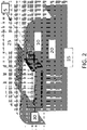
- FIG. 2 shows the embodiment of the clean chamber 5 of FIG. 1 , where air 25 from outside the unit enters the air supply unit 30 and passes through it such that the output of air supply unit produces clean and vertical laminar flow 35 through the clean chamber 5 to the 3D printer (not shown). Additional, an exhaust vent (not shown) is positioned on the bottom of the chamber.
- FIGS. 3 and 4 show a particular embodiment of a clean chamber housing integrated with a 3D bioprinter.
- the integrated clean chamber-3D bioprinter 105 has a powder coated steel frame 145 which is designed to be chemically resistant to form a cubicle-shaped housing.
- the housing further comprises a front door 160 which can have a seal to form an airlock when shut and two windows 150 on either side of the housing for viewing inside.
- the front door can be made of glass, plexiglass, or plastic to provide a view inside the print bed when the door is shut.
- On top of the housing is an air supply unit 130, which includes a small fan and HEPA filter. Below the front door of the housing are various displays and controls 165 for interfacing with the 3D bioprinter inside.
- the displays or controls include displays for pressure sensors and an off/on switch.
- various components of the 3D bioprinter inside can be seen including a moveable platform or print bed 190 and syringes 185 for extrusion.
- the moveable print bed can support multiwell plates, petri dishes, and/or glass slides.
- a vent 155 for discharging air passing through the clean chamber.
- Embodiments of the invention provide for additional features of the 3D bioprinter inside the clean chamber which can include the following.
- the bioprinter can contain a UV curing light with wavelength ranging from 300nm to 500nm, as well as a UV light for sterilization of the printing area.
- the bioprinter can have print heads for printing eukaryotic and prokaryotic cells within, on and without hydrogels.
- the print heads can dispense materials with dynamic viscosity ranges of 0.001 to 20,000 Pa-s (1 to 20,000,000 centiPoise cP).
- the print heads can be used to dispense biomaterials, hydrogels, materials prepared from decellularized human and animal tissues and organs, as well as cells in suspension in a defined and non-defined pattern.
- the print heads are capable of dispensing these biomaterials to create a 3D structure, including those containing eukaryotic and prokaryotic cells.
- the bioprinter can contain between 1 to 20 print heads, such as 1, 2, 3, 4, 5, 6, 7, 8, 9, 10, 11, 12, 13, 14, 15, 16, 17, 18, 19, or 20 print heads.
- the print heads can be positioned apart from each other with a distance of between 1 mm to 100 mm.
- the print heads can dispense material such as bioinks through needles with straight or conical tips and co-axial needles.
- the bioinks can be mixed with human cells prior to dispensing.
- embodiments provide a print bed where the material can be dispensed on a removable substrate or directly on top of the print bed itself.
- the print bed can hold petri dishes, multi well plates, and/or glass slides.
- the bioprinter dispenses materials using pneumatic pressure, mechanical pressure, heated extrusion, hydraulic extrusion, or pneumatic extrusion, or by way of a jet printer with piezoelectric applicator or jet dispenser with pneumatic applicator.
- the print heads and print beds are positioned under the high efficiency air filter(s) so that they directly receive filtered air entering the clean chamber. The filtered air and positive pressure created inside the clean chamber allows for sterile printing of cell-laden and cell-free 3D structures.
- the housing can accommodate a 3D printer or bioprinter of a variety of other configurations, non-limiting examples of which are described in U.S. Patent Nos. 7051654 , 8241905 , 8691274 , 9149952 as well as U.S. Patent Application Publication No. 20130302872 .
- This invention contemplates that the housing can be configured to house any 3D printer or bioprinter known in the art, as well as future improvements in 3D printer or bioprinter technology.
- the housing of the clean chamber can be manufactured together with the 3D printer or bioprinter in an integrated fashion, or alternatively, it can be retrofitted to accommodate the 3D printer or bioprinter.
- kits for 3D printing or 3D bioprinting includes an integrated clean chamber-3D bioprinter, as well as various reagents and consumables for use in the 3D bioprinter such as hydrogels, syringes, binding agents, cells, multiwell plates, petri dishes, replacement filters, and the like.
Landscapes
- Engineering & Computer Science (AREA)
- Chemical & Material Sciences (AREA)
- Materials Engineering (AREA)
- Manufacturing & Machinery (AREA)
- Health & Medical Sciences (AREA)
- Mechanical Engineering (AREA)
- Optics & Photonics (AREA)
- Physics & Mathematics (AREA)
- Life Sciences & Earth Sciences (AREA)
- General Engineering & Computer Science (AREA)
- Chemical Kinetics & Catalysis (AREA)
- Clinical Laboratory Science (AREA)
- Organic Chemistry (AREA)
- Toxicology (AREA)
- Zoology (AREA)
- Wood Science & Technology (AREA)
- Biomedical Technology (AREA)
- Genetics & Genomics (AREA)
- Bioinformatics & Cheminformatics (AREA)
- Combustion & Propulsion (AREA)
- Sustainable Development (AREA)
- Biotechnology (AREA)
- Environmental & Geological Engineering (AREA)
- Molecular Biology (AREA)
- Microbiology (AREA)
- General Health & Medical Sciences (AREA)
- Biochemistry (AREA)
Description
- This application relies on the disclosure of and claims priority to and the benefit of the filing date of
U.S. Provisional Application No. 62/212,324, filed August 31, 2015 - The present invention relates to 3D printers and bioprinters, and more particularly, to technology that provides a clean-air operating environment, with reduced contaminants, pollutants and particles, for 3D printers and bioprinters without the use of clean room facilities.
- Three-dimensional (3D) printing and 3D bioprinting are additive manufacturing technologies in which a material or biomaterial can be deposited layer by layer in a predetermined pattern using a 3D printer or bioprinter. In 3D bioprinting, the biomaterial may be any form, such as liquid, hydrogel or paste-like, and it can be mixed with animal or human cells to produce tissue models or organs. Sterility is a major issue in these operations. It is normally solved by placing the 3D bioprinter in a clean room, which is very expensive and limited to special certified facilities. Thus, there is a need in the art for improvements which overcome these disadvantages.
-
CN 204 547 088 U discloses a casing of environmental protection for a 3D printer wherein gases discharged from the casing are filtered, thus limiting the release of harmful substances in the surrounding environment during 3D printing. - The article "WiiBoox One Mini Review" (22 August 2015, XP055566861, https://www.3dengr.com/ wiiboox-one-mini-review.html) discloses a portable desktop 3D printer designed for home or office use and incorporating an air particle filtration system.
- The article "Afinia H800 3D Printer User's Manual - Version 1.2" (XP055566714) describes the commercial 3D printer H800 from Afinia 3D and mentions the presence of a HEPA filter therein.
- The article "Deposition of Cell-Laden Hydrogels in a Complex Geometry Using a 3D BioPrinter" from SARAH GRACE DENNIS ET AL in MICROSCOPY AND MICROANALYSIS (DOI: 10.1017/ S1431927615003906) shows a bioprinter enclosed in an airtight containment chamber with filtered intake and exhaust that maintains an internal positive pressure to reduce risk of contamination.
- The invention is defined by the appended claims. Embodiments of the invention provide clean chamber technology for 3D printers and bioprinters. In embodiments, the technology provides a clean environment for 3D bioprinting of human tissue models and organs and 3D cell culturing without requiring clean room facilities. In the context of the claimed invention, a chamber or enclosure with a metallic frame is provided which is fully or relatively airtight so that positive pressure can be created inside the printing chamber. Unfiltered air is drawn from outside into the chamber through a high efficiency filter such as a High-Efficiency Particulate Arresting (HEPA) filter, using an electrically powered fan, filtering out at least about 99% of particles and contaminants. The filtered air is then blown preferably in a very smooth, laminar flow towards into the printing chamber and out through vents within the frame.
- Embodiments of the invention provide a clean chamber which includes a housing and an air supply unit and one or more vents disposed within the housing. The housing is adapted to house a 3D printer or bioprinter and has a volume that is less than 1 m3. The air supply unit and one or more vents can be configured to provide laminar air flow inside the housing. The laminar flow may be vertical or horizontal. The air supply unit includes a high efficiency filter and a fan and the high efficiency filter can be a HEPA filter or an Ultra Low Penetration Air (ULPA) filter. The air supply unit and one or more vents are configured to provide positive pressure inside the housing, such as a positive pressure differential of 0.05 cm to 0.5 cm (0.02 in to 0.2 in) water column. The housing further includes doors or ports configured to provide access to the 3D printer or bioprinter as well as windows adapted for viewing the 3D printer or bioprinter. The housing further includes a sealing system around the windows and doors to make the housing airtight. The housing can be constructed of materials which include one or more of steel, stainless steel, aluminum, titanium, glass, or plastic, or any combination thereof.
- According to the invention, the clean chamber is included in a laboratory instrument, which clean chamber includes a housing and an air supply unit and one or more vents disposed within the housing. The laboratory instrument further includes a 3D printer which includes a 3D printing platform or print bed and one or more fluid sources adapted for 3D printing disposed above the print bed. The 3D printer is disposed within the housing such that the 3D print bed is disposed between the air supply unit and the one or more vents. Further, the clean chamber is capable of maintaining positive pressure inside by way of the air supply unit such as a positive differential pressure in the range of 0.05 cm to 0.5 cm (0.02 in to 0.2 in) water column. In embodiments, the housing further includes one or more controls or displays for interfacing with the 3D printer. The housing further includes a door adapted for providing access inside the housing and at least one window adapted for viewing inside the housing. The air supply unit is disposed at the top of the housing and the one or more vents are disposed at the sides or the bottom of the housing. In this embodiment, the air supply unit and one or more vents are configured to provide vertical laminar air flow which is disposed above the 3D print bed. In embodiments, the air supply unit comprises a fan and a high efficiency filter such as a HEPA filter or an ULPA filter. The housing is made of a material which includes one or more of steel, stainless steel, aluminum, titanium, glass, or plastic. According to the claimed invention, the instrument is dimensioned to be less than 1 m3, and, preferably, has a footprint (such as a base with a length and width) that is smaller than the depth of a standard laboratory bench, i.e. 60 cm.
- The accompanying drawings illustrate certain aspects of embodiments of the present invention, and should not be used to limit the invention. Together with the written description the drawings serve to explain certain principles of the invention.
-
FIG.1 is a schematic diagram showing a top view of the clean chamber technology according to an embodiment of the invention. -
FIG. 2 is a schematic diagram showing a detailed configuration of the high efficiency filter and electrically powered fan according to an embodiment of the invention. -
FIG. 3 is a photograph showing a side view of an integrated clean chamber-3D bioprinter according to a particular embodiment of the invention. -
FIG. 4 is a photograph showing a front view of an integrated clean chamber-3D bioprinter according to a particular embodiment of the invention. - Reference will now be made in detail to various exemplary embodiments of the invention. It is to be understood that the following discussion of exemplary embodiments is not intended as a limitation on the invention. Rather, the following discussion is provided to give the reader a more detailed understanding of certain aspects and features of the invention.
- The present invention provides a clean chamber adapted to house or contain a 3D printer such as a 3D bioprinter. The clean chamber may be a separate housing that surrounds the 3D printer, or may be integrated with the 3D printer. The clean chamber is sized such that it is adapted to surround or encompass the 3D printer while minimizing additional space. The inventive clean chamber provides a zone of purified air surrounding the 3D printer that can be housed in a standard laboratory facility that does not meet clean room specifications.
- Thus, according to the claimed invention, the clean chamber is a small sized unit, smaller than 1m3, with an integrated air supply unit. Dimensions of the clean chamber may vary, but are typically configured such that the clean chamber takes up a volume that is less than 10x, 9x, 8x, 7x, 6x, 5x, 4x, 3x, or 2x the volume of the 3D printer itself. In some embodiments, the volume of the clean chamber is less than 1.9x, 1.8x, 1.7x, 1.6x, 1.5x, 1.4x, 1.3x, 1.2x, 1.1x the volume of the 3D printer. The shape of the clean chamber can vary, but generally a square or rectangular cuboid, or box-like shape, is preferred. Exemplary dimensions of the clean chamber include 100cm x 90cm x 90cm, 90cm x 80cm x 80cm, 80cm x 80cm x 80cm, 90cm x 90cm x 80cm, 95cm x 80cm x 80cm, 80cm x 80cm x 75cm, 75cm x 75cm x75cm, 80cm x 70cm x 70cm, 70cm x 70cm x 70cm, 60cm x 60cm x 60cm, 50cm x 50cm x 50cm, and so on. In embodiments, the dimensions of the clean chamber can accommodate any 3D printer or bioprinter, including inkjet, laser-assisted, and extrusion 3D printers or bioprinters. In certain embodiments, the clean chamber is dimensioned to have a footprint that fits on a standard laboratory bench and is less than 0.5m3 in volume, such as 40cm x 40cm x 50cm, and 40cm x 40cm x 40cm and has a weight in the range of about 13.6-22.7 kg (30-50 lbs), which includes the 3D bioprinter inside. In specific embodiments, the clean chamber has exemplary dimensions of 33cm x 30cm x 38cm or 33cm x 30cm x 47cm and has a weight of approximately 18.1 kg (40 lbs), including the 3D bioprinter.
- According to the claimed invention, the clean chamber provides transparent windows and doors for viewing or access to various components of the 3D printer. For example, the windows and door may provide viewing or access to components such as motors, print heads, print bed, substrates for printing, printed structures, cartridges, syringes, platforms, lasers and controls. Additionally, the clean chamber may provide ports for cables which connect to the 3D printer, such as power cables, USB cables, and the like.
- In one embodiment, the clean chamber provides transparent windows for viewing specific operating components of the 3D printer. The transparent windows may be made of glass, plexiglass, plastic, or the like. Some embodiments provide arm ports with sleeves and gloves made of an airtight material such as acrylic, PVC, rubber, or polypropylene. In this embodiment, the clean chamber allows the operator access to the 3D printer while maintaining a clean air environment inside the clean chamber surrounding the 3D printer. Alternatively or in addition, doors or ports can be provided which allow the operator to insert or remove materials inside the chamber and allow access to the 3D printer. The doors or ports can be designed to minimize the introduction of particulate matter inside the chamber. In some embodiments, the doors and ports are transparent to provide for viewing of the 3D printer and can be made of glass, plexiglass, or plastic. The doors or ports may have an airtight sealed closed position, or an open position which allows access to the 3D printer. In the open position, the positive pressure environment inside the clean chamber ensures that no contaminants are introduced inside the chamber. Alternatively or in addition, the clean chamber can be equipped with an Ultraviolet C germicidal lamp (100-280nm, 4.43-12.4eV) to sterilize the interior of the 3D printer, particularly the print bed, before usage to prevent contamination by inactivating bacteria, viruses, and protozoa that may enter the clean chamber. The doors or ports are optimally positioned to allow access to various components of the 3D printer or bioprinter that may need removal or replacement, such as syringes containing printing materials, or 3D printed materials from the print bed of the printer. The doors or ports may also provide access to operating controls of the printer. Additionally, the clean chamber can be integrated with the 3D printer or bioprinter in a manner which allows for operation of the 3D printer while maintaining a clean air environment. For example, the print bed of the 3D printer may be configured as or enclosed in a sliding access door or tray that allows removal of 3D printed products. Again, the positive pressure environment maintained by the air supply unit ensures that unfiltered air does not enter the clean chamber when sliding access door or other ports are open. In another embodiment, the controls of the 3D printer are provided outside the housing of the clean chamber, and transmit commands to the 3D printer. In this way, the 3D printer is controlled without an operator having to breach the airtight housing to control the printer. Alternatively, the housing may have USB ports which are wired to the 3D printer, and the 3D printer can be controlled through a computer, motherboard or processor connected to the housing through the USB ports. The firmware installed in the computer of the 3D printer can be programmed to control the speed of the fan or blower in the high efficiency filtration system through a micro controller and a metal-oxide-semiconductor field-effect transistor or any other type of transistor used for amplifying or switching electronic signals. Alternatively, the speed of the fan or blower can be controlled through the software interface in an external computer device. The air flow speed, high efficiency filter life cycle and particle count in the clean chamber can be displayed in the touch-screen or LCD display in the 3D printer and in the software interface.
- According to the claimed invention, a sealing system is provided around the windows, doors, and/or ports of the clean chamber. The sealing system can be made of rubber, silicone, or foam in combination with an adhesive. The sealing system ensures that the clean chamber may maintain a positive pressure environment when air is introduced inside the chamber. The sealing system can be disposed at the interface of the windows and doors with the housing to ensure the inside of the housing is airtight or substantially airtight. Such airtight housing allows the air supply unit (described below) to maintain a positive pressure inside the housing.
- According to the claimed invention, the clean chamber includes an air supply unit. The air supply unit includes a blower or fan in communication with a high efficiency filter. The high efficiency filter may be a High-Efficiency Particulate Arresting (HEPA) filter, Ultra Low Penetration Air (ULPA) filter, or the like. In particular embodiments, the high efficiency filter may be, at a minimum, a HEPA filter class EU10, which has an efficiency of 95-99.9%. In other embodiments, the HEPA filter may be up to class U17, which has an efficiency of 99.999995%. Embodiments provide a filtration system which brings non-filtered air from the outside environment of the bioprinter and pushes it through the high efficiency filter with the help of a fan to the inside of the clean chamber, when moving volumes of air with small increase in pressure, or with the help of a blower, when moving volumes of air with moderate increase of pressure. Alternatively, the air can be pushed through the high efficiency filter using an air pump. The filtration system is designed so that all of the air drawn into bioprinter is expelled through the filter such that none of the air leaks past the filter. In embodiments, the filtration system is capable of covering an area between 25 cm2 and 2 m2, such as an area of about 25 cm2, 50 cm2, 75 cm2, 1 m2, 1.25 m2, 1.5 m2, 1.75 m2, or 2 m2 or higher depending on the size of the printer or bioprinter and number of print heads that the clean chamber must accommodate. In embodiments, the volume of air that can be treated can range up to 1 m3, up to 2 m3, up to 3 m3, up to 4 m3, up to 5 m3, or up to 6 m3 and so on depending on the bioprinter requirements. Additionally, the filtration system can incorporate high-energy UV light units to kill off the live bacteria and viruses trapped by the high efficiency filter.
- In some embodiments, the high efficiency filter is placed ahead of the output of the blower or fan such that the filter directly receives the output. In other embodiments, the high efficiency filter is placed behind the blower or fan such that incoming air first passes through the filter before entering the blower or fan. In other embodiments, two high efficiency filters are placed, with one placed before the blower or fan and one placed after the blower or fan. The blower or fan may have a single phase electric motor, or alternatively, a three phase motor. Further, the electric motor may run on AC or DC electric power sources. Alternatively or in addition, the blower or fan may be powered by a battery such that the clean chamber is operable during power outages. Further, in embodiments the blower or fan is configured to have different speeds. One particular embodiment provides a variable speed fan that is driven by a variable speed drive. The variable speed fan provides for precise control of air flow inside the clean chamber. The air supply unit is operated at a flow which is designed to maintain a positive pressure differential inside the chamber in comparison to the outside pressure. Thus, should any leaks in the sealing system occur, the pressurized air inside the chamber will leak outward rather than inward, ensuring that contaminated air does not leak in.
- In some embodiments, the high efficiency air filter(s) filter out at least 99% of the particles from ambient air surrounding the chamber. According to the claimed invention, the high efficiency air filter(s) filters out at least about 95%, preferably at least 96%, 97%, 98%, 99%, 99.1%, 99.2%, 99.3%, 99.4%, 99.5%, 99.6%, 99.7%, 99.8%, 99.9%, 99.95%, 99.96%, 99.97%, 99.98%, 99.99%, 99.995%, 99.999%, 99.9999%, 99.99999%, 99.999995% or more of particles of 0.30 microns or greater from ambient air surrounding the chamber. In embodiments, the high efficiency air filter(s) provide a sterile, or almost sterile environment inside the chamber. This allows for 3D manufacturing of printed tissues or organs.
- According to the claimed invention, the air supply unit is positioned on top of the clean chamber and receives unfiltered air from the surrounding laboratory environment. The air supply unit then pushes filtered air downwards so that it surrounds the 3D printer while creating and maintaining a positive pressure environment inside the chamber. After passing the 3D printer, the filtered air exits the clean chamber through one or more vents positioned on the bottom of the clean chamber. In this way, the clean chamber may provide a laminar or unidirectional (i.e. vertical) stream of filtered air across the 3D printer. However, in some further configurations not forming part of the claimed invention, the clean chamber is configured to provide a horizontal laminar flow by changing the position of the air supply unit and/or vents. In other configurations, the clean chamber is configured to have non-unidirectional (e.g. turbulent) or mixed air flow patterns.
- According to the claimed invention, the air supply unit creates a positive pressure inside the chamber that is higher than the ambient pressure surrounding the chamber by having an air flow that is higher than the output through the exhaust vents. This can be achieved by constricting flow through the exhaust vents through obstruction or coupling the exhaust vents with a fan to provide an exhaust unit that has an output that is lower than the fan of the air supply unit. In this way, the exhaust vents ventilate the air and assist in controlling the air flow and pressure inside the clean chamber. The positive pressure inside the chamber is preferably higher than 1 atmosphere pressure (atm). In some embodiments, the differential pressure inside the chamber is in the range of 0.05 cm to 0.5 cm (0.02 in to 0.2 in) water column (H2O), which is similar to the positive pressure inside standard clean rooms. However, in some further configurations not forming part of the claimed invention, the outputs of the air supply units and exhaust units can be adjusted to provide negative pressure inside the chamber. In some embodiments, multiple air supply units and/or exhaust units are used to move air through the clean chamber. In some embodiments, the clean chamber is equipped with pressure sensors for measuring the air pressure inside the chamber and displays on the outer portion of the housing for displaying the air pressure.
- In some embodiments, the air supply unit provides a flow inside the clean chamber at a rate of at least 0.51 cm/s (1 foot/minute). In some embodiments, the air supply unit provides a flow inside the clean chamber at a rate of at least 1.02 cm/s (2 feet/minute, preferably at least 3, 4, 5, 10, 15, 20, 25, 30, 35, 40, 45, 50, 55, 60, 65, 70, 75, 80, 85, 90, 95, 100 feet/minute, or higher). The air supply unit and/or exhaust vent or unit may be configured to replace the air inside the chamber at rate of at least 1 air change by hour. In some embodiments, the air inside the chamber is changed at a rate of at least 2, 3, 4, 5, 10, 15, 20, 25, 30, 35, 40, 45, 50, 60, 70, 80, 80, 100, 150, 200, 250, 300, 350, 400, 450, 500, 550, 600 or more air changes per hour.
- In some embodiments, the clean chamber provides an air cleanliness that meets ISO 14644-1 Cleanroom Standards, such as ISO 1, ISO 2, ISO 3, ISO 4, ISO 4,
ISO 5, ISO 6, ISO 7, ISO 8, and ISO 9. These standards are based on the size and number of airborne particles per cubic meter of air. In other embodiments, the clean chamber provides air cleanliness that meets US Federal Standard 209E Cleanroom Standards, such asClass 1, 10, 100, 1,000, 10,000, 10,000, or 100,000. US Federal Standard 209E Cleanroom Standards are based on the number of particles 0.5µm or larger per cubic foot of air (e.g. a Class 1,000 cleanroom would indicate 1,000 particles 0.5 µm or smaller in each cubic foot of air). These standards can be met by adjusting the air flow and rate of air replacement inside the clean chamber, which is a function of the volume of air moved by the air supply unit(s) and exhaust unit(s). For example, to meet cleaner air standards, the flow of the air supply units can be increased, or additional air supply units can be fitted in the chamber when the maximum flow is reached. Whether the clean chamber meets the above standards can be confirmed through various testing procedures known in the art, such as those described in the Federal Standard 209 document or IEST-RP-CC-006: TESTING CLEANROOMS, which is available on the Institute of Environmental Sciences and Technology (IEST) website. - The clean chamber may be made of a combination of steel, stainless steel, aluminum, titanium, glass, plastic, or any combination of these materials. In some embodiments, the clean chamber is an enclosure made of a steel, stainless steel, or powder coated steel frame and glass or plastic windows or doors. Further, the edges of the clean chamber may be rounded on the bottom, top, and or sides of the clean chamber. Additionally, the clean chamber may have casters or wheels on the bottom so that it me be easily moved, or feet on the bottom for providing stability on a flat surface such as a benchtop.
- The following figures are intended to illustrate a particular embodiment of the invention.
FIG. 1 shows an embodiment of aclean chamber 5 in which anair supply unit 30 is positioned on the top of theclean chamber 5. In this embodiment, theair supply unit 30 includes aHEPA filter 10 and afan unit 20, where theHEPA filter 10 is positioned immediately before thefan unit 20 at its intake.FIG. 2 shows the embodiment of theclean chamber 5 ofFIG. 1 , whereair 25 from outside the unit enters theair supply unit 30 and passes through it such that the output of air supply unit produces clean and verticallaminar flow 35 through theclean chamber 5 to the 3D printer (not shown). Additional, an exhaust vent (not shown) is positioned on the bottom of the chamber. -
FIGS. 3 and4 show a particular embodiment of a clean chamber housing integrated with a 3D bioprinter. The integrated clean chamber-3D bioprinter 105 has a powder coatedsteel frame 145 which is designed to be chemically resistant to form a cubicle-shaped housing. The housing further comprises afront door 160 which can have a seal to form an airlock when shut and twowindows 150 on either side of the housing for viewing inside. The front door can be made of glass, plexiglass, or plastic to provide a view inside the print bed when the door is shut. On top of the housing is anair supply unit 130, which includes a small fan and HEPA filter. Below the front door of the housing are various displays and controls 165 for interfacing with the 3D bioprinter inside. The displays or controls include displays for pressure sensors and an off/on switch. Inside the housing various components of the 3D bioprinter inside can be seen including a moveable platform or print bed 190 andsyringes 185 for extrusion. The moveable print bed can support multiwell plates, petri dishes, and/or glass slides. At the bottom of thewindow 150 is avent 155 for discharging air passing through the clean chamber. - Embodiments of the invention provide for additional features of the 3D bioprinter inside the clean chamber which can include the following. The bioprinter can contain a UV curing light with wavelength ranging from 300nm to 500nm, as well as a UV light for sterilization of the printing area. The bioprinter can have print heads for printing eukaryotic and prokaryotic cells within, on and without hydrogels. The print heads can dispense materials with dynamic viscosity ranges of 0.001 to 20,000 Pa-s (1 to 20,000,000 centiPoise cP). The print heads can be used to dispense biomaterials, hydrogels, materials prepared from decellularized human and animal tissues and organs, as well as cells in suspension in a defined and non-defined pattern. The print heads are capable of dispensing these biomaterials to create a 3D structure, including those containing eukaryotic and prokaryotic cells. In embodiments, the bioprinter can contain between 1 to 20 print heads, such as 1, 2, 3, 4, 5, 6, 7, 8, 9, 10, 11, 12, 13, 14, 15, 16, 17, 18, 19, or 20 print heads. The print heads can be positioned apart from each other with a distance of between 1 mm to 100 mm. The print heads can dispense material such as bioinks through needles with straight or conical tips and co-axial needles. The bioinks can be mixed with human cells prior to dispensing. Further, embodiments provide a print bed where the material can be dispensed on a removable substrate or directly on top of the print bed itself. The print bed can hold petri dishes, multi well plates, and/or glass slides. The bioprinter dispenses materials using pneumatic pressure, mechanical pressure, heated extrusion, hydraulic extrusion, or pneumatic extrusion, or by way of a jet printer with piezoelectric applicator or jet dispenser with pneumatic applicator. In embodiments, the print heads and print beds are positioned under the high efficiency air filter(s) so that they directly receive filtered air entering the clean chamber. The filtered air and positive pressure created inside the clean chamber allows for sterile printing of cell-laden and cell-free 3D structures.
- In alternative embodiments, the housing can accommodate a 3D printer or bioprinter of a variety of other configurations, non-limiting examples of which are described in
U.S. Patent Nos. 7051654 ,8241905 ,8691274 ,9149952 U.S. Patent Application Publication No. 20130302872 . This invention contemplates that the housing can be configured to house any 3D printer or bioprinter known in the art, as well as future improvements in 3D printer or bioprinter technology. The housing of the clean chamber can be manufactured together with the 3D printer or bioprinter in an integrated fashion, or alternatively, it can be retrofitted to accommodate the 3D printer or bioprinter. - Additional embodiments provide a kit for 3D printing or 3D bioprinting. The kit includes an integrated clean chamber-3D bioprinter, as well as various reagents and consumables for use in the 3D bioprinter such as hydrogels, syringes, binding agents, cells, multiwell plates, petri dishes, replacement filters, and the like.
- The present invention has been described with reference to particular embodiments having various features. In light of the disclosure provided above, it will be apparent to those skilled in the art that various modifications and variations can be made in the practice of the present invention without departing from the scope of the invention which is defined by the appended claims. One skilled in the art will recognize that the disclosed features may be used singularly, in any combination, or omitted based on the requirements and specifications of a given application or design. When an embodiment refers to "comprising" certain features, it is to be understood that the embodiments can alternatively "consist of' or "consist essentially of' any one or more of the features. Other embodiments of the invention will be apparent to those skilled in the art from consideration of the specification and practice of the invention.
- It is noted in particular that where a range of values is provided in this specification, each value between the upper and lower limits of that range is also specifically disclosed. The upper and lower limits of these smaller ranges may independently be included or excluded in the range as well. The singular forms "a," "an," and "the" include plural referents unless the context clearly dictates otherwise. It is intended that the specification and examples be considered as exemplary in nature. Further, all of the references cited in this disclosure are intended to provide an efficient way of supplementing the enabling disclosure of this invention as well as provide background detailing the level of ordinary skill in the art.
Claims (11)
- A laboratory instrument, comprising:a clean chamber (5, 105), comprisinga housing adapted to house a 3D printer or bioprinter, wherein the housing comprises a metal frame (145);an air supply unit (30, 130) comprising a blower or fan (20) and being adapted to bring filtered air into the housing from outside the housing;and one or more vents (155) disposed within the housing; said vents (155) being adapted to let air exit the housing;a plurality of windows (150) and doors (160) disposed within the housing that provide viewing or access to portions of the 3D printer or bioprinter;a sealing system around the doors (160) and windows (150) of the housing;wherein together the air supply unit (30, 130), one or more vents (155), and sealing system are configured to provide positive pressure and an essentially clean environment inside the housing;wherein the clean chamber (5, 105) is capable of maintaining positive pressure inside by way of the air supply unit (30, 130);
anda 3D printer comprising:a 3D printbed (190);one or more fluid sources adapted for 3D printing disposed above the printbed (190);characterized in that said air supply unit (30, 130) comprises a high-efficiency air filter (10); said filter (10) being adapted to filter out at least 95% of particles of 0.30 microns or greater in ambient air surrounding the housing; andwherein the air supply unit (30, 130) is disposed within the housing and at the top of the housing, and the one or more vents (155) are disposed at the sides or the bottom of the housing, andwherein the housing has a volume that is less than 1m3; andwherein the 3D printer is disposed within the housing such that the 3D printbed (190) is disposed between the air supply unit (30, 130) and the one or more vents (155). - The laboratory instrument of claim 1, wherein the housing further comprises one or more controls or displays (165) for interfacing with the 3D printer.
- The laboratory instrument of claim 1, wherein the positive pressure inside the housing is in the range of 0.05 cm to 0.5 cm (0.02 in. to 0.2 in) water column.
- The laboratory instrument of claim 1, wherein the housing comprises one or more of steel, stainless steel, aluminum, titanium, glass, or plastic.
- The laboratory instrument of claim 1, wherein the air supply unit (30, 130) and one or more vents (155) are configured to provide vertical laminar flow (35), and wherein the vertical laminar flow (35) is disposed above the 3D printbed (190).
- The laboratory instrument of claim 1, wherein the 3D printbed (190) is adapted to support a multiwell plate or a petri dish.
- The laboratory instrument of claim 1, wherein the 3D printer is a 3D bioprinter.
- The laboratory instrument of any of the previous claims, further comprising a UV light source.
- The laboratory instrument of claim 8, wherein the UV light source comprises a UV curing light with wavelength ranging from 300 nm to 500 nm.
- The laboratory instrument of claim 8 or 9, further comprising a UV light with wavelength ranging from 100 nm to 280 nm for sterilization of the printing area.
- The laboratory instrument of any of the previous claims, wherein the clean chamber housing is integrated with a 3D bioprinter comprising a moveable platform or printbed (190) and syringes (185) for extrusion.
Priority Applications (1)
| Application Number | Priority Date | Filing Date | Title |
|---|---|---|---|
| EP21166018.8A EP3862086A1 (en) | 2015-08-31 | 2016-08-31 | Clean chamber technology for 3d printers and bioprinters |
Applications Claiming Priority (2)
| Application Number | Priority Date | Filing Date | Title |
|---|---|---|---|
| US201562212324P | 2015-08-31 | 2015-08-31 | |
| PCT/US2016/049716 WO2017040675A1 (en) | 2015-08-31 | 2016-08-31 | Clean chamber technology for 3d printers and bioprinters |
Related Child Applications (1)
| Application Number | Title | Priority Date | Filing Date |
|---|---|---|---|
| EP21166018.8A Division EP3862086A1 (en) | 2015-08-31 | 2016-08-31 | Clean chamber technology for 3d printers and bioprinters |
Publications (3)
| Publication Number | Publication Date |
|---|---|
| EP3344387A1 EP3344387A1 (en) | 2018-07-11 |
| EP3344387A4 EP3344387A4 (en) | 2019-04-24 |
| EP3344387B1 true EP3344387B1 (en) | 2021-04-07 |
Family
ID=58188244
Family Applications (2)
| Application Number | Title | Priority Date | Filing Date |
|---|---|---|---|
| EP16842913.2A Active EP3344387B1 (en) | 2015-08-31 | 2016-08-31 | Clean chamber technology for 3d printers and bioprinters |
| EP21166018.8A Withdrawn EP3862086A1 (en) | 2015-08-31 | 2016-08-31 | Clean chamber technology for 3d printers and bioprinters |
Family Applications After (1)
| Application Number | Title | Priority Date | Filing Date |
|---|---|---|---|
| EP21166018.8A Withdrawn EP3862086A1 (en) | 2015-08-31 | 2016-08-31 | Clean chamber technology for 3d printers and bioprinters |
Country Status (5)
| Country | Link |
|---|---|
| US (1) | US11370171B2 (en) |
| EP (2) | EP3344387B1 (en) |
| KR (3) | KR20190057168A (en) |
| ES (1) | ES2878120T3 (en) |
| WO (1) | WO2017040675A1 (en) |
Families Citing this family (44)
| Publication number | Priority date | Publication date | Assignee | Title |
|---|---|---|---|---|
| KR20170037020A (en) * | 2015-09-25 | 2017-04-04 | 전자부품연구원 | Information Insert in 3D Structure and Non-Destructive Information Recognition Method |
| US11691341B2 (en) * | 2015-10-30 | 2023-07-04 | Seurat Technologies, Inc. | Part manipulation using printed manipulation points |
| US11285228B2 (en) * | 2015-11-05 | 2022-03-29 | Vitae Industries, Inc. | Method and apparatus for sterilized 3D printing |
| DE202017002012U1 (en) * | 2016-05-17 | 2017-08-21 | Brand Gmbh + Co Kg | Housing for a laboratory device |
| US20180095450A1 (en) | 2016-09-30 | 2018-04-05 | Velo3D, Inc. | Three-dimensional objects and their formation |
| KR101828345B1 (en) * | 2016-10-19 | 2018-03-29 | 주식회사 로킷 | Bio 3d printer |
| CN106827518B (en) * | 2017-04-10 | 2023-05-30 | 云南增材佳唯科技有限公司 | Tandem type photosensitive resin 3D printing all-in-one machine for printing medical instruments |
| CN107505959A (en) * | 2017-09-14 | 2017-12-22 | 广州迈普再生医学科技有限公司 | The temperature and cleanliness factor control system of a kind of 3D printer closing space and biological 3D printer |
| WO2019060680A1 (en) | 2017-09-22 | 2019-03-28 | The Regents Of The University Of Colorado, A Body Corporate | Organ-on-chip microphysiological system |
| DE102017122849A1 (en) | 2017-10-02 | 2019-04-04 | Stefan Fischer | Fluid supply system for a 3D printer |
| IT201700118967A1 (en) * | 2017-10-20 | 2019-04-20 | Travaglini S P A | CULTIVATION METHOD OF AGRICULTURAL PRODUCTS IN ENVIRONMENTS CLOSED INCLUDING A PLURALITY OF AIR-CONDITIONED PREMISES |
| CN111655451A (en) * | 2017-11-29 | 2020-09-11 | 奥里根生物治疗公司 | Aseptic Additive Manufacturing System |
| KR102645547B1 (en) * | 2017-12-08 | 2024-03-11 | 인벤티아 라이프 사이언스 피티와이 엘티디 | Bioprinter for manufacturing 3D cellular constructs |
| WO2019114771A1 (en) * | 2017-12-12 | 2019-06-20 | Chow Chun To | An apparatus and method for three-dimensional (3d) printing/bio-printing |
| KR102069725B1 (en) | 2018-01-16 | 2020-01-23 | 주식회사 더하임 | A Filter Unit For 3D Printer |
| WO2019145795A2 (en) | 2018-01-26 | 2019-08-01 | Cellink Ab | Systems and methods for optical assessments of bioink printability |
| US11679546B2 (en) * | 2018-02-09 | 2023-06-20 | The Regents Of The University Of Colorado, A Body Corporate | Bioprinter and methods of manufacturing an organomimetic device |
| US11480560B2 (en) | 2018-06-11 | 2022-10-25 | The Regents Of The University Of Colorado, A Body Corporate | Delivery of aerosolized respiratory pathogens |
| US11426818B2 (en) | 2018-08-10 | 2022-08-30 | The Research Foundation for the State University | Additive manufacturing processes and additively manufactured products |
| EP3623136B1 (en) * | 2018-09-14 | 2023-11-29 | Fraunhofer-Gesellschaft zur Förderung der angewandten Forschung e.V. | Method for producing three-dimensional hydrogel structures and device for the layerwise building-up of such hydrogel structures |
| US11186736B2 (en) | 2018-10-10 | 2021-11-30 | Cellink Ab | Double network bioinks |
| FR3087702B1 (en) | 2018-10-25 | 2021-03-19 | Poietis | ISOLATED BIO-PRINTING DEVICE |
| CN113165374B (en) * | 2018-12-06 | 2022-12-16 | 英文提亚生命科学有限公司 | Printhead components for 3D bioprinters |
| GB201820397D0 (en) * | 2018-12-14 | 2019-01-30 | Secure Micro Solutions Ltd | Safety apparatus and method |
| CA3148849A1 (en) | 2019-07-26 | 2021-02-04 | Velo3D, Inc. | Quality assurance in formation of three-dimensional objects |
| DE102019122302A1 (en) | 2019-08-20 | 2021-02-25 | Kumovis GmbH | Print head for an additive manufacturing system as well as an additive manufacturing system |
| DE102019122291A1 (en) | 2019-08-20 | 2021-02-25 | Kumovis GmbH | Positioning system for an additive manufacturing system as well as an additive manufacturing system |
| DE102019122286B4 (en) | 2019-08-20 | 2024-09-19 | Kumovis GmbH | 3D printer for 3D printing of plastics for medical applications |
| DE102019122282B4 (en) * | 2019-08-20 | 2025-08-07 | Kumovis GmbH | Storage compartment for printing material of an additive manufacturing system, in particular a 3D printer and additive manufacturing system |
| WO2021040723A1 (en) | 2019-08-29 | 2021-03-04 | Hewlett-Packard Development Company, L.P. | Pressure-regulating apparatus for three-dimensional printer |
| US11826951B2 (en) | 2019-09-06 | 2023-11-28 | Cellink Ab | Temperature-controlled multi-material overprinting |
| KR102335747B1 (en) * | 2019-12-24 | 2021-12-08 | (주)캐리마 | Manufacturing system of an artificial eye |
| KR102357162B1 (en) * | 2020-06-09 | 2022-01-28 | 주식회사 로킷헬스케어 | Chamber environmental control system for bio 3d printer |
| IL301022B2 (en) * | 2020-09-09 | 2024-01-01 | Jabil Inc | A 3D printed support block with an improved design |
| KR102932741B1 (en) | 2020-11-03 | 2026-03-04 | 김재욱 | A 3D printer |
| AU2021377710B2 (en) | 2020-11-16 | 2023-10-19 | Craitor, Inc. | Portable, ruggedized and easy to use 3d printing system |
| US12162074B2 (en) | 2020-11-25 | 2024-12-10 | Lawrence Livermore National Security, Llc | System and method for large-area pulsed laser melting of metallic powder in a laser powder bed fusion application |
| WO2022177496A1 (en) | 2021-02-17 | 2022-08-25 | Bico Group Ab | Bioprinting workflow systems and methods |
| US20240157629A1 (en) * | 2021-03-12 | 2024-05-16 | Hector Martinez | 3d bioprinter with continuous workflow capability |
| WO2023039374A1 (en) * | 2021-09-07 | 2023-03-16 | Donaldson Company, Inc. | Fume extractor system and methods |
| CN113757833B (en) * | 2021-09-14 | 2022-04-08 | 北京联合大学 | Method and system for switching between production mode and duty mode based on data-driven |
| WO2023172389A1 (en) * | 2022-03-11 | 2023-09-14 | Velo3D, Inc., | Viewing window assemblies |
| KR20240006327A (en) | 2022-07-06 | 2024-01-15 | 한국기계연구원 | Impurity removal apparatus in gas, three dimension printer having them and gas control method using them |
| PT118381A (en) | 2022-12-07 | 2024-06-07 | Inst Politecnico De Leiria | INTEGRATED BIOFABRICATION SYSTEM FOR THE PRODUCTION OF THREE-DIMENSIONAL STRUCTURES |
Family Cites Families (27)
| Publication number | Priority date | Publication date | Assignee | Title |
|---|---|---|---|---|
| SU1112193A1 (en) | 1983-01-18 | 1984-09-07 | Ленинградский научно-исследовательский институт гигиены труда и профзаболеваний | Dust protection chamber for work table |
| US5083558A (en) | 1990-11-06 | 1992-01-28 | Thomas William R | Mobile surgical compartment with micro filtered laminar air flow |
| US5563767A (en) * | 1995-05-04 | 1996-10-08 | Chen; Teng-Chun | Drawer type hard diskdrive adapter |
| US6722872B1 (en) | 1999-06-23 | 2004-04-20 | Stratasys, Inc. | High temperature modeling apparatus |
| US7027887B2 (en) * | 2002-07-03 | 2006-04-11 | Theries, Llc | Apparatus, systems and methods for use in three-dimensional printing |
| RU28639U1 (en) | 2002-10-01 | 2003-04-10 | Общество с ограниченной ответственностью "Диапазон-Мед" | Laboratory cabinet for sterile work |
| US7051654B2 (en) | 2003-05-30 | 2006-05-30 | Clemson University | Ink-jet printing of viable cells |
| US8241905B2 (en) | 2004-02-24 | 2012-08-14 | The Curators Of The University Of Missouri | Self-assembling cell aggregates and methods of making engineered tissue using the same |
| WO2006020685A2 (en) | 2004-08-11 | 2006-02-23 | Cornell Research Foundation, Inc. | Modular fabrication systems and methods |
| JP4701458B2 (en) | 2006-03-28 | 2011-06-15 | 独立行政法人放射線医学総合研究所 | Clean bench for handling radiopharmaceuticals |
| JP2009047613A (en) | 2007-08-22 | 2009-03-05 | Kubota Konpusu Kk | Bio-printer |
| US8691274B2 (en) | 2008-02-14 | 2014-04-08 | Wake Forest University Health Sciences | Inkjet printing of tissues and cells |
| KR101711354B1 (en) | 2008-06-24 | 2017-02-28 | 더 큐레이터스 오브 더 유니버시티 오브 미주리 | Self-assembling multicellular bodies and methods of producing a three-dimensional biological structure using the same |
| JP5540304B2 (en) | 2008-07-17 | 2014-07-02 | 独立行政法人理化学研究所 | Fabrication of three-dimensional cellular tissue using electrostatic inkjet phenomenon |
| CN104324563B (en) * | 2010-06-18 | 2016-01-20 | 株式会社爱瑞思 | Filter unit |
| EP2629975B1 (en) | 2010-10-21 | 2022-03-09 | Organovo, Inc. | Devices for the fabrication of tissue |
| US9499779B2 (en) | 2012-04-20 | 2016-11-22 | Organovo, Inc. | Devices, systems, and methods for the fabrication of tissue utilizing UV cross-linking |
| JP6397420B2 (en) | 2012-11-05 | 2018-09-26 | ストラタシス リミテッド | Direct inkjet printing system and method for 3D objects |
| KR20160036619A (en) * | 2013-07-31 | 2016-04-04 | 오가노보, 인크. | Automated devices, systems, and methods for the fabrication of tissue |
| US9764515B2 (en) * | 2014-05-01 | 2017-09-19 | Musc Foundation For Research Development | Multidispensor cartesian robotic printer |
| US20150321419A1 (en) * | 2014-05-06 | 2015-11-12 | Todd Linthicum | Extrusion system for additive manufacturing and 3-d printing |
| CA2962090A1 (en) | 2014-09-21 | 2016-03-24 | Made In Space, Inc. | Terrestrial and space-based manufacturing systems |
| CN104758085B (en) | 2014-12-26 | 2016-11-09 | 南京师范大学 | A three-dimensional bioprinting device and bioprinting method |
| US20160236413A1 (en) * | 2015-02-17 | 2016-08-18 | Michael Daniel Armani | Nozzle cover coating |
| CN204547088U (en) * | 2015-03-30 | 2015-08-12 | 三维泰柯(厦门)电子科技有限公司 | A kind of environmental protection 3D printer closed shell |
| CN105642891B (en) | 2015-10-14 | 2017-08-11 | 哈尔滨福沃德多维智能装备有限公司 | Laser fusion shaping dust pelletizing system and dust removal method with multifunctional circulation air-flow |
| CN205185336U (en) | 2015-12-14 | 2016-04-27 | 广西三集科技有限公司 | Novel desktop 3D printer |
-
2016
- 2016-08-31 ES ES16842913T patent/ES2878120T3/en active Active
- 2016-08-31 WO PCT/US2016/049716 patent/WO2017040675A1/en not_active Ceased
- 2016-08-31 EP EP16842913.2A patent/EP3344387B1/en active Active
- 2016-08-31 KR KR1020197014508A patent/KR20190057168A/en not_active Ceased
- 2016-08-31 US US15/755,767 patent/US11370171B2/en active Active
- 2016-08-31 KR KR1020177015356A patent/KR20170088874A/en not_active Ceased
- 2016-08-31 KR KR1020187011462A patent/KR101982328B1/en active Active
- 2016-08-31 EP EP21166018.8A patent/EP3862086A1/en not_active Withdrawn
Non-Patent Citations (1)
| Title |
|---|
| SARAH GRACE DENNIS ET AL: "Deposition of Cell-Laden Hydrogels in a Complex Geometry Using a 3D BioPrinter", MICROSCOPY AND MICROANALYSIS (PROCEEDINGS OF MICROSCOPY & MICROANALYSIS 2015; AUGUST 2-6 - PORTLAND, OR), vol. 21, no. S3, 4 August 2015 (2015-08-04), pages 621 - 622, XP055625576, ISSN: 1431-9276, DOI: 10.1017/S1431927615003906 * |
Also Published As
| Publication number | Publication date |
|---|---|
| EP3344387A1 (en) | 2018-07-11 |
| KR101982328B1 (en) | 2019-05-24 |
| US11370171B2 (en) | 2022-06-28 |
| KR20170088874A (en) | 2017-08-02 |
| EP3862086A1 (en) | 2021-08-11 |
| WO2017040675A1 (en) | 2017-03-09 |
| ES2878120T3 (en) | 2021-11-18 |
| KR20180043855A (en) | 2018-04-30 |
| US20180326665A1 (en) | 2018-11-15 |
| EP3344387A4 (en) | 2019-04-24 |
| KR20190057168A (en) | 2019-05-27 |
Similar Documents
| Publication | Publication Date | Title |
|---|---|---|
| US11370171B2 (en) | Clean chamber technology for 3D printers and bioprinters | |
| US10689606B2 (en) | Apparatus and method for three-dimensional (3D) printing/bio-printing | |
| CN101501180B (en) | Cell manipulation and cultivation equipments for the production of cell therapy products | |
| US20230158820A1 (en) | Portable cleanroom printing cabinet | |
| EP4079333A1 (en) | Germicidal apparatuses with configurations to selectively conduct different disinfection modes interior and exterior to the apparatus | |
| KR102306467B1 (en) | Portable cleanroom printing cabinet | |
| KR102132193B1 (en) | air purifier of multi type with movable and standing | |
| JP3185604U (en) | Attachment panel of cabinet for biohazard countermeasures | |
| JP6028014B2 (en) | Isolator | |
| KR101358297B1 (en) | Multi function documentary sterilization device | |
| CN213031396U (en) | Dual-purpose sterilizer | |
| CN219367834U (en) | Movable laminar flow hundred-grade clean cabin | |
| AU2022205235B2 (en) | Portable cleanroom printing cabinet | |
| KR100697095B1 (en) | Prefab Clean Bench | |
| CN213284057U (en) | Laminar flow transfer trolley for transferring sterile medicines | |
| TR2024006210Y (en) | Mobile laminar flow unit. | |
| JP2007223800A (en) | Open type clean storage device | |
| LV14930B (en) | Thermo-stabilized laminar cabinet |
Legal Events
| Date | Code | Title | Description |
|---|---|---|---|
| STAA | Information on the status of an ep patent application or granted ep patent |
Free format text: STATUS: THE INTERNATIONAL PUBLICATION HAS BEEN MADE |
|
| TPAC | Observations filed by third parties |
Free format text: ORIGINAL CODE: EPIDOSNTIPA |
|
| PUAI | Public reference made under article 153(3) epc to a published international application that has entered the european phase |
Free format text: ORIGINAL CODE: 0009012 |
|
| STAA | Information on the status of an ep patent application or granted ep patent |
Free format text: STATUS: REQUEST FOR EXAMINATION WAS MADE |
|
| 17P | Request for examination filed |
Effective date: 20180326 |
|
| AK | Designated contracting states |
Kind code of ref document: A1 Designated state(s): AL AT BE BG CH CY CZ DE DK EE ES FI FR GB GR HR HU IE IS IT LI LT LU LV MC MK MT NL NO PL PT RO RS SE SI SK SM TR |
|
| AX | Request for extension of the european patent |
Extension state: BA ME |
|
| DAV | Request for validation of the european patent (deleted) | ||
| DAX | Request for extension of the european patent (deleted) | ||
| A4 | Supplementary search report drawn up and despatched |
Effective date: 20190326 |
|
| RIC1 | Information provided on ipc code assigned before grant |
Ipc: F24F 3/16 20060101ALI20190320BHEP Ipc: F24F 13/28 20060101ALI20190320BHEP Ipc: B29C 64/364 20170101ALI20190320BHEP Ipc: F24F 11/00 20180101ALN20190320BHEP Ipc: B01L 3/02 20060101ALN20190320BHEP Ipc: B01L 1/02 20060101AFI20190320BHEP |
|
| STAA | Information on the status of an ep patent application or granted ep patent |
Free format text: STATUS: EXAMINATION IS IN PROGRESS |
|
| 17Q | First examination report despatched |
Effective date: 20191001 |
|
| RIC1 | Information provided on ipc code assigned before grant |
Ipc: B01L 1/02 20060101AFI20201019BHEP Ipc: F24F 3/16 20060101ALI20201019BHEP Ipc: F24F 13/28 20060101ALI20201019BHEP Ipc: F24F 11/00 20180101ALN20201019BHEP Ipc: B33Y 40/00 20200101ALI20201019BHEP Ipc: B29C 64/364 20170101ALI20201019BHEP Ipc: B01L 3/02 20060101ALN20201019BHEP Ipc: B29C 64/25 20170101ALI20201019BHEP |
|
| GRAP | Despatch of communication of intention to grant a patent |
Free format text: ORIGINAL CODE: EPIDOSNIGR1 |
|
| STAA | Information on the status of an ep patent application or granted ep patent |
Free format text: STATUS: GRANT OF PATENT IS INTENDED |
|
| GRAJ | Information related to disapproval of communication of intention to grant by the applicant or resumption of examination proceedings by the epo deleted |
Free format text: ORIGINAL CODE: EPIDOSDIGR1 |
|
| STAA | Information on the status of an ep patent application or granted ep patent |
Free format text: STATUS: EXAMINATION IS IN PROGRESS |
|
| INTG | Intention to grant announced |
Effective date: 20201127 |
|
| INTC | Intention to grant announced (deleted) | ||
| RIC1 | Information provided on ipc code assigned before grant |
Ipc: B29C 64/364 20170101ALI20201216BHEP Ipc: B01L 3/02 20060101ALN20201216BHEP Ipc: B29C 64/25 20170101ALI20201216BHEP Ipc: F24F 3/16 20060101ALI20201216BHEP Ipc: F24F 13/28 20060101ALI20201216BHEP Ipc: F24F 11/00 20180101ALN20201216BHEP Ipc: B01L 1/02 20060101AFI20201216BHEP Ipc: B33Y 40/00 20200101ALI20201216BHEP |
|
| GRAP | Despatch of communication of intention to grant a patent |
Free format text: ORIGINAL CODE: EPIDOSNIGR1 |
|
| STAA | Information on the status of an ep patent application or granted ep patent |
Free format text: STATUS: GRANT OF PATENT IS INTENDED |
|
| INTG | Intention to grant announced |
Effective date: 20210126 |
|
| GRAS | Grant fee paid |
Free format text: ORIGINAL CODE: EPIDOSNIGR3 |
|
| GRAA | (expected) grant |
Free format text: ORIGINAL CODE: 0009210 |
|
| STAA | Information on the status of an ep patent application or granted ep patent |
Free format text: STATUS: THE PATENT HAS BEEN GRANTED |
|
| RAP1 | Party data changed (applicant data changed or rights of an application transferred) |
Owner name: CELLINK AB |
|
| AK | Designated contracting states |
Kind code of ref document: B1 Designated state(s): AL AT BE BG CH CY CZ DE DK EE ES FI FR GB GR HR HU IE IS IT LI LT LU LV MC MK MT NL NO PL PT RO RS SE SI SK SM TR |
|
| REG | Reference to a national code |
Ref country code: GB Ref legal event code: FG4D |
|
| REG | Reference to a national code |
Ref country code: AT Ref legal event code: REF Ref document number: 1378973 Country of ref document: AT Kind code of ref document: T Effective date: 20210415 Ref country code: CH Ref legal event code: EP |
|
| REG | Reference to a national code |
Ref country code: DE Ref legal event code: R096 Ref document number: 602016055813 Country of ref document: DE |
|
| REG | Reference to a national code |
Ref country code: IE Ref legal event code: FG4D |
|
| REG | Reference to a national code |
Ref country code: FI Ref legal event code: FGE |
|
| REG | Reference to a national code |
Ref country code: SE Ref legal event code: TRGR |
|
| REG | Reference to a national code |
Ref country code: LT Ref legal event code: MG9D |
|
| REG | Reference to a national code |
Ref country code: NL Ref legal event code: MP Effective date: 20210407 Ref country code: AT Ref legal event code: MK05 Ref document number: 1378973 Country of ref document: AT Kind code of ref document: T Effective date: 20210407 |
|
| PG25 | Lapsed in a contracting state [announced via postgrant information from national office to epo] |
Ref country code: NL Free format text: LAPSE BECAUSE OF FAILURE TO SUBMIT A TRANSLATION OF THE DESCRIPTION OR TO PAY THE FEE WITHIN THE PRESCRIBED TIME-LIMIT Effective date: 20210407 Ref country code: HR Free format text: LAPSE BECAUSE OF FAILURE TO SUBMIT A TRANSLATION OF THE DESCRIPTION OR TO PAY THE FEE WITHIN THE PRESCRIBED TIME-LIMIT Effective date: 20210407 Ref country code: AT Free format text: LAPSE BECAUSE OF FAILURE TO SUBMIT A TRANSLATION OF THE DESCRIPTION OR TO PAY THE FEE WITHIN THE PRESCRIBED TIME-LIMIT Effective date: 20210407 Ref country code: BG Free format text: LAPSE BECAUSE OF FAILURE TO SUBMIT A TRANSLATION OF THE DESCRIPTION OR TO PAY THE FEE WITHIN THE PRESCRIBED TIME-LIMIT Effective date: 20210707 Ref country code: LT Free format text: LAPSE BECAUSE OF FAILURE TO SUBMIT A TRANSLATION OF THE DESCRIPTION OR TO PAY THE FEE WITHIN THE PRESCRIBED TIME-LIMIT Effective date: 20210407 |
|
| REG | Reference to a national code |
Ref country code: ES Ref legal event code: FG2A Ref document number: 2878120 Country of ref document: ES Kind code of ref document: T3 Effective date: 20211118 |
|
| PG25 | Lapsed in a contracting state [announced via postgrant information from national office to epo] |
Ref country code: PT Free format text: LAPSE BECAUSE OF FAILURE TO SUBMIT A TRANSLATION OF THE DESCRIPTION OR TO PAY THE FEE WITHIN THE PRESCRIBED TIME-LIMIT Effective date: 20210809 Ref country code: NO Free format text: LAPSE BECAUSE OF FAILURE TO SUBMIT A TRANSLATION OF THE DESCRIPTION OR TO PAY THE FEE WITHIN THE PRESCRIBED TIME-LIMIT Effective date: 20210707 Ref country code: PL Free format text: LAPSE BECAUSE OF FAILURE TO SUBMIT A TRANSLATION OF THE DESCRIPTION OR TO PAY THE FEE WITHIN THE PRESCRIBED TIME-LIMIT Effective date: 20210407 Ref country code: RS Free format text: LAPSE BECAUSE OF FAILURE TO SUBMIT A TRANSLATION OF THE DESCRIPTION OR TO PAY THE FEE WITHIN THE PRESCRIBED TIME-LIMIT Effective date: 20210407 Ref country code: GR Free format text: LAPSE BECAUSE OF FAILURE TO SUBMIT A TRANSLATION OF THE DESCRIPTION OR TO PAY THE FEE WITHIN THE PRESCRIBED TIME-LIMIT Effective date: 20210708 Ref country code: IS Free format text: LAPSE BECAUSE OF FAILURE TO SUBMIT A TRANSLATION OF THE DESCRIPTION OR TO PAY THE FEE WITHIN THE PRESCRIBED TIME-LIMIT Effective date: 20210807 Ref country code: LV Free format text: LAPSE BECAUSE OF FAILURE TO SUBMIT A TRANSLATION OF THE DESCRIPTION OR TO PAY THE FEE WITHIN THE PRESCRIBED TIME-LIMIT Effective date: 20210407 |
|
| REG | Reference to a national code |
Ref country code: DE Ref legal event code: R097 Ref document number: 602016055813 Country of ref document: DE |
|
| PG25 | Lapsed in a contracting state [announced via postgrant information from national office to epo] |
Ref country code: RO Free format text: LAPSE BECAUSE OF FAILURE TO SUBMIT A TRANSLATION OF THE DESCRIPTION OR TO PAY THE FEE WITHIN THE PRESCRIBED TIME-LIMIT Effective date: 20210407 Ref country code: CZ Free format text: LAPSE BECAUSE OF FAILURE TO SUBMIT A TRANSLATION OF THE DESCRIPTION OR TO PAY THE FEE WITHIN THE PRESCRIBED TIME-LIMIT Effective date: 20210407 Ref country code: DK Free format text: LAPSE BECAUSE OF FAILURE TO SUBMIT A TRANSLATION OF THE DESCRIPTION OR TO PAY THE FEE WITHIN THE PRESCRIBED TIME-LIMIT Effective date: 20210407 Ref country code: EE Free format text: LAPSE BECAUSE OF FAILURE TO SUBMIT A TRANSLATION OF THE DESCRIPTION OR TO PAY THE FEE WITHIN THE PRESCRIBED TIME-LIMIT Effective date: 20210407 Ref country code: SM Free format text: LAPSE BECAUSE OF FAILURE TO SUBMIT A TRANSLATION OF THE DESCRIPTION OR TO PAY THE FEE WITHIN THE PRESCRIBED TIME-LIMIT Effective date: 20210407 Ref country code: SK Free format text: LAPSE BECAUSE OF FAILURE TO SUBMIT A TRANSLATION OF THE DESCRIPTION OR TO PAY THE FEE WITHIN THE PRESCRIBED TIME-LIMIT Effective date: 20210407 |
|
| PLBE | No opposition filed within time limit |
Free format text: ORIGINAL CODE: 0009261 |
|
| STAA | Information on the status of an ep patent application or granted ep patent |
Free format text: STATUS: NO OPPOSITION FILED WITHIN TIME LIMIT |
|
| 26N | No opposition filed |
Effective date: 20220110 |
|
| PG25 | Lapsed in a contracting state [announced via postgrant information from national office to epo] |
Ref country code: MC Free format text: LAPSE BECAUSE OF FAILURE TO SUBMIT A TRANSLATION OF THE DESCRIPTION OR TO PAY THE FEE WITHIN THE PRESCRIBED TIME-LIMIT Effective date: 20210407 |
|
| REG | Reference to a national code |
Ref country code: BE Ref legal event code: MM Effective date: 20210831 |
|
| PG25 | Lapsed in a contracting state [announced via postgrant information from national office to epo] |
Ref country code: IS Free format text: LAPSE BECAUSE OF FAILURE TO SUBMIT A TRANSLATION OF THE DESCRIPTION OR TO PAY THE FEE WITHIN THE PRESCRIBED TIME-LIMIT Effective date: 20210807 Ref country code: LU Free format text: LAPSE BECAUSE OF NON-PAYMENT OF DUE FEES Effective date: 20210831 Ref country code: AL Free format text: LAPSE BECAUSE OF FAILURE TO SUBMIT A TRANSLATION OF THE DESCRIPTION OR TO PAY THE FEE WITHIN THE PRESCRIBED TIME-LIMIT Effective date: 20210407 |
|
| REG | Reference to a national code |
Ref country code: FI Ref legal event code: PCE Owner name: CELLINK BIOPRINTING AB |
|
| PG25 | Lapsed in a contracting state [announced via postgrant information from national office to epo] |
Ref country code: IE Free format text: LAPSE BECAUSE OF NON-PAYMENT OF DUE FEES Effective date: 20210831 Ref country code: BE Free format text: LAPSE BECAUSE OF NON-PAYMENT OF DUE FEES Effective date: 20210831 |
|
| REG | Reference to a national code |
Ref country code: DE Ref legal event code: R081 Ref document number: 602016055813 Country of ref document: DE Owner name: CELLINK BIOPRINTING AB, SE Free format text: FORMER OWNER: CELLINK AB, GOTHENBURG, SE Ref country code: GB Ref legal event code: 732E Free format text: REGISTERED BETWEEN 20221020 AND 20221026 |
|
| PG25 | Lapsed in a contracting state [announced via postgrant information from national office to epo] |
Ref country code: HU Free format text: LAPSE BECAUSE OF FAILURE TO SUBMIT A TRANSLATION OF THE DESCRIPTION OR TO PAY THE FEE WITHIN THE PRESCRIBED TIME-LIMIT; INVALID AB INITIO Effective date: 20160831 |
|
| PG25 | Lapsed in a contracting state [announced via postgrant information from national office to epo] |
Ref country code: CY Free format text: LAPSE BECAUSE OF FAILURE TO SUBMIT A TRANSLATION OF THE DESCRIPTION OR TO PAY THE FEE WITHIN THE PRESCRIBED TIME-LIMIT Effective date: 20210407 |
|
| P01 | Opt-out of the competence of the unified patent court (upc) registered |
Effective date: 20230526 |
|
| PG25 | Lapsed in a contracting state [announced via postgrant information from national office to epo] |
Ref country code: MK Free format text: LAPSE BECAUSE OF FAILURE TO SUBMIT A TRANSLATION OF THE DESCRIPTION OR TO PAY THE FEE WITHIN THE PRESCRIBED TIME-LIMIT Effective date: 20210407 |
|
| REG | Reference to a national code |
Ref country code: ES Ref legal event code: PC2A Owner name: BICO GROUP AB Effective date: 20240625 |
|
| PG25 | Lapsed in a contracting state [announced via postgrant information from national office to epo] |
Ref country code: MT Free format text: LAPSE BECAUSE OF FAILURE TO SUBMIT A TRANSLATION OF THE DESCRIPTION OR TO PAY THE FEE WITHIN THE PRESCRIBED TIME-LIMIT Effective date: 20210407 |
|
| PGFP | Annual fee paid to national office [announced via postgrant information from national office to epo] |
Ref country code: FI Payment date: 20240716 Year of fee payment: 9 |
|
| PGFP | Annual fee paid to national office [announced via postgrant information from national office to epo] |
Ref country code: CH Payment date: 20240901 Year of fee payment: 9 |
|
| PGFP | Annual fee paid to national office [announced via postgrant information from national office to epo] |
Ref country code: SE Payment date: 20240624 Year of fee payment: 9 |
|
| REG | Reference to a national code |
Ref country code: DE Ref legal event code: R082 Ref document number: 602016055813 Country of ref document: DE |
|
| PGFP | Annual fee paid to national office [announced via postgrant information from national office to epo] |
Ref country code: DE Payment date: 20250804 Year of fee payment: 10 |
|
| PGFP | Annual fee paid to national office [announced via postgrant information from national office to epo] |
Ref country code: IT Payment date: 20250821 Year of fee payment: 10 |
|
| PGFP | Annual fee paid to national office [announced via postgrant information from national office to epo] |
Ref country code: GB Payment date: 20250828 Year of fee payment: 10 |
|
| PGFP | Annual fee paid to national office [announced via postgrant information from national office to epo] |
Ref country code: FR Payment date: 20250804 Year of fee payment: 10 |
|
| PG25 | Lapsed in a contracting state [announced via postgrant information from national office to epo] |
Ref country code: TR Free format text: LAPSE BECAUSE OF FAILURE TO SUBMIT A TRANSLATION OF THE DESCRIPTION OR TO PAY THE FEE WITHIN THE PRESCRIBED TIME-LIMIT Effective date: 20210407 |
|
| PGFP | Annual fee paid to national office [announced via postgrant information from national office to epo] |
Ref country code: ES Payment date: 20251027 Year of fee payment: 10 |
|
| REG | Reference to a national code |
Ref country code: CH Ref legal event code: H13 Free format text: ST27 STATUS EVENT CODE: U-0-0-H10-H13 (AS PROVIDED BY THE NATIONAL OFFICE) Effective date: 20260324 |
|
| PG25 | Lapsed in a contracting state [announced via postgrant information from national office to epo] |
Ref country code: FI Free format text: LAPSE BECAUSE OF NON-PAYMENT OF DUE FEES Effective date: 20250831 |
|
| PG25 | Lapsed in a contracting state [announced via postgrant information from national office to epo] |
Ref country code: CH Free format text: LAPSE BECAUSE OF NON-PAYMENT OF DUE FEES Effective date: 20250831 |