EP3344384B1 - Integrated scr and ammonia oxidation catalyst systems - Google Patents
Integrated scr and ammonia oxidation catalyst systems Download PDFInfo
- Publication number
- EP3344384B1 EP3344384B1 EP16757666.9A EP16757666A EP3344384B1 EP 3344384 B1 EP3344384 B1 EP 3344384B1 EP 16757666 A EP16757666 A EP 16757666A EP 3344384 B1 EP3344384 B1 EP 3344384B1
- Authority
- EP
- European Patent Office
- Prior art keywords
- catalyst
- molecular sieve
- washcoat
- platinum
- ammonia
- Prior art date
- Legal status (The legal status is an assumption and is not a legal conclusion. Google has not performed a legal analysis and makes no representation as to the accuracy of the status listed.)
- Active
Links
Images

Classifications
-
- B—PERFORMING OPERATIONS; TRANSPORTING
- B01—PHYSICAL OR CHEMICAL PROCESSES OR APPARATUS IN GENERAL
- B01D—SEPARATION
- B01D53/00—Separation of gases or vapours; Recovering vapours of volatile solvents from gases; Chemical or biological purification of waste gases, e.g. engine exhaust gases, smoke, fumes, flue gases, aerosols
- B01D53/34—Chemical or biological purification of waste gases
- B01D53/92—Chemical or biological purification of waste gases of engine exhaust gases
- B01D53/94—Chemical or biological purification of waste gases of engine exhaust gases by catalytic processes
- B01D53/9404—Removing only nitrogen compounds
- B01D53/9409—Nitrogen oxides
- B01D53/9413—Processes characterised by a specific catalyst
- B01D53/9418—Processes characterised by a specific catalyst for removing nitrogen oxides by selective catalytic reduction [SCR] using a reducing agent in a lean exhaust gas
-
- B—PERFORMING OPERATIONS; TRANSPORTING
- B01—PHYSICAL OR CHEMICAL PROCESSES OR APPARATUS IN GENERAL
- B01D—SEPARATION
- B01D53/00—Separation of gases or vapours; Recovering vapours of volatile solvents from gases; Chemical or biological purification of waste gases, e.g. engine exhaust gases, smoke, fumes, flue gases, aerosols
- B01D53/34—Chemical or biological purification of waste gases
- B01D53/92—Chemical or biological purification of waste gases of engine exhaust gases
- B01D53/94—Chemical or biological purification of waste gases of engine exhaust gases by catalytic processes
- B01D53/9404—Removing only nitrogen compounds
- B01D53/9436—Ammonia
-
- B—PERFORMING OPERATIONS; TRANSPORTING
- B01—PHYSICAL OR CHEMICAL PROCESSES OR APPARATUS IN GENERAL
- B01D—SEPARATION
- B01D53/00—Separation of gases or vapours; Recovering vapours of volatile solvents from gases; Chemical or biological purification of waste gases, e.g. engine exhaust gases, smoke, fumes, flue gases, aerosols
- B01D53/34—Chemical or biological purification of waste gases
- B01D53/92—Chemical or biological purification of waste gases of engine exhaust gases
- B01D53/94—Chemical or biological purification of waste gases of engine exhaust gases by catalytic processes
- B01D53/9459—Removing one or more of nitrogen oxides, carbon monoxide, or hydrocarbons by multiple successive catalytic functions; systems with more than one different function, e.g. zone coated catalysts
- B01D53/9477—Removing one or more of nitrogen oxides, carbon monoxide, or hydrocarbons by multiple successive catalytic functions; systems with more than one different function, e.g. zone coated catalysts with catalysts positioned on separate bricks, e.g. exhaust systems
-
- B—PERFORMING OPERATIONS; TRANSPORTING
- B01—PHYSICAL OR CHEMICAL PROCESSES OR APPARATUS IN GENERAL
- B01J—CHEMICAL OR PHYSICAL PROCESSES, e.g. CATALYSIS OR COLLOID CHEMISTRY; THEIR RELEVANT APPARATUS
- B01J23/00—Catalysts comprising metals or metal oxides or hydroxides, not provided for in group B01J21/00
- B01J23/38—Catalysts comprising metals or metal oxides or hydroxides, not provided for in group B01J21/00 of noble metals
- B01J23/40—Catalysts comprising metals or metal oxides or hydroxides, not provided for in group B01J21/00 of noble metals of the platinum group metals
- B01J23/42—Platinum
-
- B—PERFORMING OPERATIONS; TRANSPORTING
- B01—PHYSICAL OR CHEMICAL PROCESSES OR APPARATUS IN GENERAL
- B01J—CHEMICAL OR PHYSICAL PROCESSES, e.g. CATALYSIS OR COLLOID CHEMISTRY; THEIR RELEVANT APPARATUS
- B01J23/00—Catalysts comprising metals or metal oxides or hydroxides, not provided for in group B01J21/00
- B01J23/38—Catalysts comprising metals or metal oxides or hydroxides, not provided for in group B01J21/00 of noble metals
- B01J23/40—Catalysts comprising metals or metal oxides or hydroxides, not provided for in group B01J21/00 of noble metals of the platinum group metals
- B01J23/46—Ruthenium, rhodium, osmium or iridium
- B01J23/464—Rhodium
-
- B—PERFORMING OPERATIONS; TRANSPORTING
- B01—PHYSICAL OR CHEMICAL PROCESSES OR APPARATUS IN GENERAL
- B01J—CHEMICAL OR PHYSICAL PROCESSES, e.g. CATALYSIS OR COLLOID CHEMISTRY; THEIR RELEVANT APPARATUS
- B01J29/00—Catalysts comprising molecular sieves
- B01J29/04—Catalysts comprising molecular sieves having base-exchange properties, e.g. crystalline zeolites
- B01J29/06—Crystalline aluminosilicate zeolites; Isomorphous compounds thereof
- B01J29/70—Crystalline aluminosilicate zeolites; Isomorphous compounds thereof of types characterised by their specific structure not provided for in groups B01J29/08 - B01J29/65
- B01J29/72—Crystalline aluminosilicate zeolites; Isomorphous compounds thereof of types characterised by their specific structure not provided for in groups B01J29/08 - B01J29/65 containing iron group metals, noble metals or copper
- B01J29/76—Iron group metals or copper
- B01J29/763—CHA-type, e.g. Chabazite, LZ-218
-
- B—PERFORMING OPERATIONS; TRANSPORTING
- B01—PHYSICAL OR CHEMICAL PROCESSES OR APPARATUS IN GENERAL
- B01J—CHEMICAL OR PHYSICAL PROCESSES, e.g. CATALYSIS OR COLLOID CHEMISTRY; THEIR RELEVANT APPARATUS
- B01J35/00—Catalysts, in general, characterised by their form or physical properties
- B01J35/19—Catalysts containing parts with different compositions
-
- B—PERFORMING OPERATIONS; TRANSPORTING
- B01—PHYSICAL OR CHEMICAL PROCESSES OR APPARATUS IN GENERAL
- B01J—CHEMICAL OR PHYSICAL PROCESSES, e.g. CATALYSIS OR COLLOID CHEMISTRY; THEIR RELEVANT APPARATUS
- B01J37/00—Processes, in general, for preparing catalysts; Processes, in general, for activation of catalysts
- B01J37/02—Impregnation, coating or precipitation
- B01J37/024—Multiple impregnation or coating
- B01J37/0244—Coatings comprising several layers
-
- B—PERFORMING OPERATIONS; TRANSPORTING
- B01—PHYSICAL OR CHEMICAL PROCESSES OR APPARATUS IN GENERAL
- B01J—CHEMICAL OR PHYSICAL PROCESSES, e.g. CATALYSIS OR COLLOID CHEMISTRY; THEIR RELEVANT APPARATUS
- B01J37/00—Processes, in general, for preparing catalysts; Processes, in general, for activation of catalysts
- B01J37/02—Impregnation, coating or precipitation
- B01J37/024—Multiple impregnation or coating
- B01J37/0246—Coatings comprising a zeolite
-
- F—MECHANICAL ENGINEERING; LIGHTING; HEATING; WEAPONS; BLASTING
- F01—MACHINES OR ENGINES IN GENERAL; ENGINE PLANTS IN GENERAL; STEAM ENGINES
- F01N—GAS-FLOW SILENCERS OR EXHAUST APPARATUS FOR MACHINES OR ENGINES IN GENERAL; GAS-FLOW SILENCERS OR EXHAUST APPARATUS FOR INTERNAL-COMBUSTION ENGINES
- F01N3/00—Exhaust or silencing apparatus having means for purifying, rendering innocuous, or otherwise treating exhaust
- F01N3/08—Exhaust or silencing apparatus having means for purifying, rendering innocuous, or otherwise treating exhaust for rendering innocuous
- F01N3/10—Exhaust or silencing apparatus having means for purifying, rendering innocuous, or otherwise treating exhaust for rendering innocuous by thermal or catalytic conversion of noxious components of exhaust
- F01N3/18—Exhaust or silencing apparatus having means for purifying, rendering innocuous, or otherwise treating exhaust for rendering innocuous by thermal or catalytic conversion of noxious components of exhaust characterised by methods of operation; Control
- F01N3/20—Exhaust or silencing apparatus having means for purifying, rendering innocuous, or otherwise treating exhaust for rendering innocuous by thermal or catalytic conversion of noxious components of exhaust characterised by methods of operation; Control specially adapted for catalytic conversion
- F01N3/206—Adding periodically or continuously substances to exhaust gases for promoting purification, e.g. catalytic material in liquid form, NOx reducing agents
- F01N3/2066—Selective catalytic reduction [SCR]
-
- B—PERFORMING OPERATIONS; TRANSPORTING
- B01—PHYSICAL OR CHEMICAL PROCESSES OR APPARATUS IN GENERAL
- B01D—SEPARATION
- B01D2255/00—Catalysts
- B01D2255/10—Noble metals or compounds thereof
- B01D2255/102—Platinum group metals
- B01D2255/1021—Platinum
-
- B—PERFORMING OPERATIONS; TRANSPORTING
- B01—PHYSICAL OR CHEMICAL PROCESSES OR APPARATUS IN GENERAL
- B01D—SEPARATION
- B01D2255/00—Catalysts
- B01D2255/10—Noble metals or compounds thereof
- B01D2255/102—Platinum group metals
- B01D2255/1025—Rhodium
-
- B—PERFORMING OPERATIONS; TRANSPORTING
- B01—PHYSICAL OR CHEMICAL PROCESSES OR APPARATUS IN GENERAL
- B01D—SEPARATION
- B01D2255/00—Catalysts
- B01D2255/20—Metals or compounds thereof
- B01D2255/204—Alkaline earth metals
- B01D2255/2042—Barium
-
- B—PERFORMING OPERATIONS; TRANSPORTING
- B01—PHYSICAL OR CHEMICAL PROCESSES OR APPARATUS IN GENERAL
- B01D—SEPARATION
- B01D2255/00—Catalysts
- B01D2255/20—Metals or compounds thereof
- B01D2255/206—Rare earth metals
- B01D2255/2063—Lanthanum
-
- B—PERFORMING OPERATIONS; TRANSPORTING
- B01—PHYSICAL OR CHEMICAL PROCESSES OR APPARATUS IN GENERAL
- B01D—SEPARATION
- B01D2255/00—Catalysts
- B01D2255/20—Metals or compounds thereof
- B01D2255/206—Rare earth metals
- B01D2255/2065—Cerium
-
- B—PERFORMING OPERATIONS; TRANSPORTING
- B01—PHYSICAL OR CHEMICAL PROCESSES OR APPARATUS IN GENERAL
- B01D—SEPARATION
- B01D2255/00—Catalysts
- B01D2255/20—Metals or compounds thereof
- B01D2255/207—Transition metals
- B01D2255/20707—Titanium
-
- B—PERFORMING OPERATIONS; TRANSPORTING
- B01—PHYSICAL OR CHEMICAL PROCESSES OR APPARATUS IN GENERAL
- B01D—SEPARATION
- B01D2255/00—Catalysts
- B01D2255/20—Metals or compounds thereof
- B01D2255/207—Transition metals
- B01D2255/20715—Zirconium
-
- B—PERFORMING OPERATIONS; TRANSPORTING
- B01—PHYSICAL OR CHEMICAL PROCESSES OR APPARATUS IN GENERAL
- B01D—SEPARATION
- B01D2255/00—Catalysts
- B01D2255/20—Metals or compounds thereof
- B01D2255/207—Transition metals
- B01D2255/2073—Manganese
-
- B—PERFORMING OPERATIONS; TRANSPORTING
- B01—PHYSICAL OR CHEMICAL PROCESSES OR APPARATUS IN GENERAL
- B01D—SEPARATION
- B01D2255/00—Catalysts
- B01D2255/20—Metals or compounds thereof
- B01D2255/207—Transition metals
- B01D2255/20769—Molybdenum
-
- B—PERFORMING OPERATIONS; TRANSPORTING
- B01—PHYSICAL OR CHEMICAL PROCESSES OR APPARATUS IN GENERAL
- B01D—SEPARATION
- B01D2255/00—Catalysts
- B01D2255/20—Metals or compounds thereof
- B01D2255/207—Transition metals
- B01D2255/20776—Tungsten
-
- B—PERFORMING OPERATIONS; TRANSPORTING
- B01—PHYSICAL OR CHEMICAL PROCESSES OR APPARATUS IN GENERAL
- B01D—SEPARATION
- B01D2255/00—Catalysts
- B01D2255/20—Metals or compounds thereof
- B01D2255/209—Other metals
- B01D2255/2092—Aluminium
-
- B—PERFORMING OPERATIONS; TRANSPORTING
- B01—PHYSICAL OR CHEMICAL PROCESSES OR APPARATUS IN GENERAL
- B01D—SEPARATION
- B01D2255/00—Catalysts
- B01D2255/50—Zeolites
-
- B—PERFORMING OPERATIONS; TRANSPORTING
- B01—PHYSICAL OR CHEMICAL PROCESSES OR APPARATUS IN GENERAL
- B01D—SEPARATION
- B01D2255/00—Catalysts
- B01D2255/90—Physical characteristics of catalysts
- B01D2255/92—Dimensions
- B01D2255/9205—Porosity
-
- Y—GENERAL TAGGING OF NEW TECHNOLOGICAL DEVELOPMENTS; GENERAL TAGGING OF CROSS-SECTIONAL TECHNOLOGIES SPANNING OVER SEVERAL SECTIONS OF THE IPC; TECHNICAL SUBJECTS COVERED BY FORMER USPC CROSS-REFERENCE ART COLLECTIONS [XRACs] AND DIGESTS
- Y02—TECHNOLOGIES OR APPLICATIONS FOR MITIGATION OR ADAPTATION AGAINST CLIMATE CHANGE
- Y02T—CLIMATE CHANGE MITIGATION TECHNOLOGIES RELATED TO TRANSPORTATION
- Y02T10/00—Road transport of goods or passengers
- Y02T10/10—Internal combustion engine [ICE] based vehicles
- Y02T10/12—Improving ICE efficiencies
Definitions
- the invention pertains to catalysts, methods of treating emissions in an exhaust stream, and systems for treating emissions produced in an exhaust gas stream.
- Diesel engine exhaust is a heterogeneous mixture that contains particulate emissions such as soot and gaseous emissions such as carbon monoxide, unburned or partially burned hydrocarbons, and nitrogen oxides (collectively referred to as NO x ).
- Catalyst compositions often disposed on one or more monolithic substrates, are placed in engine exhaust systems to convert certain or all of these exhaust components to innocuous compounds.
- Ammonia selective catalytic reduction is a NO x abatement technology that will be used to meet strict NO x emission targets in diesel and lean-burn engines.
- NO x normally consisting of NO + NO 2
- ammonia or an ammonia precursor such as urea
- N 2 dinitrogen
- This technology is capable of NO x conversions greater than 90% over a typical diesel driving cycle, and thus it represents one of the best approaches for achieving aggressive NO x abatement goals.
- a characteristic feature of some ammonia SCR catalyst materials is a propensity to retain considerable amounts of ammonia on Lewis and Br ⁇ nsted acidic sites on the catalyst surface during low temperature portions of a typical driving cycle.
- a subsequent increase in exhaust temperature can cause ammonia to desorb from the ammonia SCR catalyst surface and exit the exhaust pipe of the vehicle.
- Overdosing ammonia in order to increase NO x conversion rate is another potential scenario where ammonia may exit from the ammonia SCR catalyst.
- Ammonia slip from the ammonia SCR catalyst presents a number of problems.
- the odor threshold for NH 3 is 20 ppm in air. Eye and throat irritation are noticeable above 100 ppm, skin irritation occurs above 400 ppm, and the IDLH is 500 ppm in air.
- NH 3 is caustic, especially in its aqueous form. Condensation of NH 3 and water in cooler regions of the exhaust line downstream of the exhaust catalysts will give a corrosive mixture.
- a selective ammonia oxidation (AMOx) catalyst is employed for this purpose, with the objective to convert the excess ammonia to N 2 .
- WO2010/062730 describes the application of an undercoat with Pt on alumina located in the outlet zone of the monolith with an overlayer of copper on chabazite distributed over the entire length of a monolithic converter.
- WO 2012/075400 A1 discloses a catalyst composition comprising extra-framework metal Cu or Fe on a zeolitic material CHA and a platinum group metal such as Pt which can be supported on alumina.
- US 2011/0182791 A1 discloses a catalytic system comprising an ammonia oxidation catalyst which comprises a first layer comprising Cu-CHA and a second layer comprising a platinum group metal, preferably Pt, which can be supported on alumina or zirconia.
- EP 2878360 A1 discloses an exhaust gas purification catalyst comprising a lower layer comprising a NOx reduction catalyst, a front upper layer comprising a NOx reduction catalyst and a rear upper layer comprising an oxidation catalyst.
- catalyst systems for treating an exhaust gas stream, and methods of preparing catalysts for the treatment of such gas.
- catalyst system shall include two or more chemical catalytic functions on one substrate or on more than one separate substrate.
- a first aspect of the invention is directed to a catalyst for oxidizing ammonia.
- a catalyst for oxidizing ammonia comprises: a washcoat including copper or iron on a small pore molecular sieve material having a maximum ring size of eight tetrahedral atoms physically mixed with platinum and rhodium on a refractory metal oxide support including alumina, silica, zirconia, titania, and physical mixtures or chemical combinations thereof, including atomically doped combinations.
- the catalyst of the first embodiment is modified, wherein the washcoat is disposed on a monolithic substrate.
- the catalyst of the second embodiment is modified, wherein the monolithic substrate is a flow-through honeycomb substrate comprising a plurality of fine, substantially parallel gas flow passages extending along a longitudinal axis of the substrate.
- the catalyst of the first through third embodiments is modified, wherein the catalyst contains an amount of platinum and an amount of rhodium.
- the catalyst of the fourth embodiment is modified, wherein the amount of platinum is present in an amount in a range of 0.01 g/l to 0.71 g/l (0.3 g/ft 3 to 20 g/ft 3 ) and rhodium is present in an amount in a range of 0.01 g/l to 0.71 g/l (0.3 g/ft 3 to 20 g/ft 3 ) and wherein there is no other platinum group metal present.
- the catalyst of the first through fifth embodiments is modified, wherein the copper or iron on a molecular sieve material and the platinum and rhodium on the refractory metal oxide support are homogenously mixed in the washcoat.
- the catalyst of the first through fifth embodiments is modified, wherein the copper or iron on a molecular sieve material and the platinum and rhodium on the refractory metal oxide support are segregated from one another and the platinum and rhodium on the refractory metal oxide support is physically mixed with copper or iron on a molecular sieve material.
- the catalyst of the first through seventh embodiments is modified, wherein the refractory metal oxide support is doped with a dopant selected from one or more of Ce, La, Ba, Zr, Hf, Ta, Mn, Si, Ti, W, Mo, and Re.
- a dopant selected from one or more of Ce, La, Ba, Zr, Hf, Ta, Mn, Si, Ti, W, Mo, and Re.
- the catalyst of the first through eighth embodiments is modified, wherein the washcoat is substantially free of copper aluminate.
- the catalyst of the first through ninth embodiments is modified, wherein the molecular sieve material is selected from framework types CHA, AEI, AFX, ERI, KFI, LEV, AFT, EAB, DDR, PAU, RHO, SAV, SAT, TSC, UEI and combinations thereof.
- the molecular sieve material is selected from framework types CHA, AEI, AFX, ERI, KFI, LEV, AFT, EAB, DDR, PAU, RHO, SAV, SAT, TSC, UEI and combinations thereof.
- the catalyst of the first through tenth embodiments is modified, wherein the molecular sieve material has the CHA framework type.
- the catalyst of the first through ninth embodiments is modified, wherein the molecular sieve material has a silica to alumina ratio in a range of 2 to 200.
- the catalyst of the first through twelfth embodiments is modified, wherein the washcoat includes copper on a small pore molecular sieve material having a maximum ring size of eight tetrahedral atoms.
- the catalyst of the first through twelfth embodiments is modified, wherein the washcoat includes iron on a small pore molecular sieve material having a maximum ring size of eight tetrahedral atoms.
- a second aspect of the present invention is directed to a catalyst for oxidizing ammonia.
- a catalyst for oxidizing ammonia comprises: a first washcoat zone including copper or iron on a small pore molecular sieve material having a maximum ring size of eight tetrahedral atoms, the first washcoat zone being substantially free of platinum group metal; and a second washcoat zone including copper or iron on a small pore molecular sieve material having a maximum ring size of eight tetrahedral atoms physically mixed with platinum and rhodium on a refractory metal oxide support including alumina, silica, zirconia, titania, and physical mixtures or chemical combinations thereof, including atomically doped combinations.
- the catalyst of the fifteenth embodiment is modified, wherein the first washcoat zone and second washcoat zone are disposed on a monolithic substrate.
- the catalyst of the sixteenth embodiment is modified, wherein the first washcoat zone and the second washcoat zone are disposed adjacent on the monolithic substrate, and the first washcoat zone is upstream from the second washcoat zone.
- the catalyst of the fifteenth through seventeenth embodiments is modified, wherein the second washcoat zone contains platinum, rhodium and no other platinum group metal.
- the catalyst of the fifteenth through eighteenth embodiments is modified, wherein the molecular sieve material is selected from framework types CHA, AEI, AFX, ERI, KFI, LEV, AFT, EAB, DDR, PAU, RHO, SAV, SAT, TSC, UEI and combinations thereof.
- the molecular sieve material is selected from framework types CHA, AEI, AFX, ERI, KFI, LEV, AFT, EAB, DDR, PAU, RHO, SAV, SAT, TSC, UEI and combinations thereof.
- the catalyst of the fifteenth through nineteenth embodiments is modified, wherein the molecular sieve material has the CHA framework type.
- the catalyst of the fifteenth through twentieth embodiments is modified, wherein the molecular sieve material has a silica to alumina ratio in a range of 2 to 200.
- a third aspect of the present invention is directed to a method for treating emissions.
- a method for treating emissions produced in an exhaust gas stream of a lean-burn engine comprises: injecting ammonia or an ammonia precursor into an exhaust gas stream containing one or more of NO x , CO, or hydrocarbons; and passing the exhaust gas stream through the catalyst of any of the first through twenty-first embodiments.
- a fourth aspect of the present invention is directed to a system for treating emissions.
- a system for treating emissions produced in an exhaust gas stream of a lean-burn engine comprises: a source of ammonia and an injector to inject the source of ammonia into the exhaust gas stream; a selective catalytic reduction catalyst downstream from the source of ammonia to promote reaction of the ammonia with nitrogen oxides to form nitrogen and H 2 O selectively; and the catalyst according to any of the first through twenty-first embodiments.
- system of twenty-third embodiment is modified wherein the system further comprises an ammonia oxidation (AMOx) catalyst.
- AMOx ammonia oxidation
- Embodiments of the invention are directed to catalysts for oxidizing ammonia.
- a first aspect of the invention is directed to a catalyst comprising a washcoat including copper or iron on a small pore molecular sieve material having a maximum ring size of eight tetrahedral atoms physically mixed with platinum and rhodium on a refractory metal oxide support including alumina, silica, zirconia, titania, and physical mixtures or chemical combinations thereof, including atomically doped combinations.
- a second aspect of the invention is directed to a catalyst comprising a first washcoat zone including copper or iron on a small pore molecular sieve material having a maximum ring size of eight tetrahedral atoms, the first washcoat zone being substantially free of platinum group metal; and a second washcoat zone including copper or iron on a small pore molecular sieve material having a maximum ring size of eight tetrahedral atoms mixed with platinum and rhodium on a refractory metal oxide support including alumina, silica, zirconia, titania, and physical mixtures or chemical combinations thereof, including atomically doped combinations.
- the catalysts are particularly suitable in exhaust gas purification catalyst components, in particular as ammonia oxidation catalysts that provide good NO x conversion with low N 2 O and NH 3 emissions. It is desirable to avoid NH 3 emissions during temperature increases that are accompanied by a strong reduction of ammonia adsorption capacity (i.e. from approximately 200 °C to 300 and 400 °C).
- exhaust stream and “engine exhaust stream” refer to the engine out effluent as well as to the effluent downstream of one or more other catalyst system components including but not limited to a diesel oxidation catalyst and/or soot filter.
- an aspect of the invention pertains to a catalyst.
- the catalyst may be disposed on a monolithic substrate as a washcoat layer.
- a washcoat layer comprises a compositionally distinct layer of material disposed on the surface of the monolithic substrate or an underlying washcoat layer.
- a washcoat typically is comprised of a high surface area carrier, for example aluminum oxide, and catalytic components such as a platinum group metal.
- a catalyst can contain one or more washcoat layers, and each washcoat layer can have unique chemical catalytic functions.
- catalyst or “catalyst composition” or “catalyst material” refers to a material that promotes a reaction.
- a catalytic article refers to an element that is used to promote a desired reaction.
- a catalytic article may comprise a washcoat containing a catalytic species, e.g. a catalyst composition, on a substrate.
- SCR selective catalytic reduction
- the selective reduction process is referred to as a SCR process (Selective Catalytic Reduction).
- the SCR process uses catalytic reduction of nitrogen oxides with ammonia in the presence of atmospheric oxygen with the formation predominantly of nitrogen and steam: 4NO + 4NH 3 + O 2 ⁇ 4N 2 +6H 2 O (standard SCR reaction) 2NO 2 + 4NH 3 ⁇ 3N 2 + 6H 2 O (slow SCR reaction) NO + NO 2 + NH 3 ⁇ 2N 2 + 3H 2 O (fast SCR reaction)
- Catalysts employed in the SCR process ideally should be able to retain good catalytic activity over the wide range of temperature conditions of use, for example, 200 °C to 600 °C or higher, under hydrothermal conditions.
- Hydrothermal conditions are often encountered in practice, such as during the regeneration of a soot filter, a component of the exhaust gas treatment system used for the removal of particles.
- NH 3 oxidation reaction or “ammonia oxidation reaction” are used herein to refer to a chemical process described by: 4 NH 3 + 5 O 2 ⁇ 4 NO + 6 H 2 O (NH 3 oxidation reaction)
- NH 3 oxidation reaction refers to a process in which ammonia (NH 3 ) is reacted with oxygen (O 2 ) to produce NO, NO 2 , N 2 O, or preferably N 2 .
- NH 3 oxidation composition refers to a material composition effective to catalyze the NH 3 oxidation reaction.
- a component effective to catalyze the SCR function (herein referred to as an "SCR component") is utilized in a washcoat as part of a NO x abatement catalyst composition.
- SCR component is part of a composition that includes other components in a washcoat.
- NO x abatement catalyst composition may include only the SCR component.
- molecular sieve refers to framework materials such as zeolites and other framework materials (e.g. isomorphously substituted materials), which may in particulate form in combination with one or more promoter metals be used as catalysts.
- Molecular sieves are materials based on an extensive three-dimensional network of oxygen ions containing generally tetrahedral type sites and having a substantially uniform pore distribution, with the average pore size being no larger than 20 ⁇ . The pore sizes are defined by the ring size.
- zeolite refers to a specific example of a molecular sieve, including silicon and aluminum atoms.
- the molecular sieves by their framework type, it is intended to include the framework type and any and all isotypic framework materials such as SAPO, ALPO and MeAPO materials having the same framework type as the zeolite materials.
- aluminosilicate zeolite excludes aluminophosphate materials such as SAPO, ALPO, and MeAPO materials, and the broader term "zeolite” is intended to include aluminosilicates and aluminophosphates.
- Zeolites are crystalline materials having rather uniform pore sizes which, depending upon the type of zeolite and the type and amount of cations included in the zeolite lattice, range from about 3 to 10 Angstroms in diameter. Zeolites generally comprise silica to alumina (SAR) molar ratios of 2 or greater.
- aluminophosphates refers to another specific example of a molecular sieve, including aluminum and phosphate atoms. Aluminophosphates are crystalline materials having rather uniform pore sizes.
- molecular sieves e.g. zeolite
- zeolite are defined as aluminosilicates with open 3-dimensional framework structures composed of corner-sharing TO 4 tetrahedra, where T is Al or Si, or optionally P.
- Cations that balance the charge of the anionic framework are loosely associated with the framework oxygens, and the remaining pore volume is filled with water molecules.
- the non-framework cations are generally exchangeable, and the water molecules removable.
- the molecular sieve materials independently, comprise SiO 4 /AlO 4 tetrahedra and are linked by common oxygen atoms to form a three-dimensional network. In other embodiments, the molecular sieve materials comprise SiO 4 /AlO 4 /PO 4 tetrahedra.
- the molecular sieve materials of one or more embodiments can be differentiated mainly according to the geometry of the voids which are formed by the rigid network of the (SiO 4 )/AlO 4 , or SiO 4 /AlO 4 /PO 4 , tetrahedra.
- the entrances to the voids are formed from 6, 8, 10, or 12 ring atoms with respect to the atoms which form the entrance opening. In one or more embodiments, the molecular sieve materials comprise ring sizes of no larger than 12, including 6, 8, 10, and 12.
- the molecular sieve materials comprise an 8-ring small pore aluminosilicate zeolite.
- small pore refers to pore openings, which are smaller than about 5 Angstroms, for example on the order of ⁇ 3.8 Angstroms.
- the phrase "8-ring" zeolites refers to zeolites having 8-ring pore openings and double-six ring secondary building units and having a cage like structure resulting from the connection of double six-ring building units by 4 rings.
- the molecular sieve material is a small pore molecular sieve having a maximum ring size of eight tetrahedral atoms.
- Zeolites are comprised of secondary building units (SBU) and composite building units (CBU), and appear in many different framework structures. Secondary building units contain up to 16 tetrahedral atoms and are non-chiral. Composite building units are not required to be achiral, and cannot necessarily be used to build the entire framework. For example, a group of zeolites have a single 4-ring (s4r) composite building unit in their framework structure. In the 4-ring, the "4" denotes the positions of tetrahedral silicon and aluminum atoms, and the oxygen atoms are located in between tetrahedral atoms.
- SBU secondary building units
- CBU composite building units
- composite building units include, for example, a single 6-ring (s6r) unit, a double 4-ring (d4r) unit, and a double 6-ring (d6r) unit.
- the d4r unit is created by joining two s4r units.
- the d6r unit is created by joining two s6r units. In a d6r unit, there are twelve tetrahedral atoms.
- Zeolitic framework types that have a d6r secondary building unit include AEI, AFT, AFX, CHA, EAB, EMT, ERI, FAU, GME, JSR, KFI, LEV, LTL, LTN, MOZ, MSO, MWW, OFF, SAS, SAT, SAV, SBS, SBT, SFW, SSF, SZR, TSC, and WEN.
- the molecular sieve materials comprise a d6r unit.
- the molecular sieve materials have a framework type selected from AEI, AFT, AFX, CHA, EAB, EMT, ERI, FAU, GME, JSR, KFI, LEV, LTL, LTN, MOZ, MSO, MWW, OFF, SAS, SAT, SAV, SBS, SBT, SFW, SSF, SZR, TSC, WEN, and combinations thereof.
- the molecular sieve materials have a framework type selected from the group consisting of CHA, AEI, AFX, ERI, KFI, LEV, AFT, EAB, DDR, PAU, RHO, SAV, SAT, TSC, UEI and combinations thereof.
- the molecular sieve materials have a framework type selected from CHA, AEI, and AFX. In one or more very specific embodiments, the molecular sieve materials have the CHA framework type.
- Zeolitic CHA-framework type molecular sieves includes a naturally occurring tectosilicate mineral of a zeolite group with approximate formula: (Ca,Na 2 ,K 2 ,Mg)Al 2 Si 4 O 12 •6H 2 O (e.g., hydrated calcium aluminum silicate).
- zeolitic CHA-framework type molecular sieves Three synthetic forms of zeolitic CHA-framework type molecular sieves are described in " Zeolite Molecular Sieves," by D. W. Breck, published in 1973 by John Wiley & Sons ,.
- the molecular sieve materials can include all aluminosilicate, borosilicate, gallosilicate, MeAPSO, and MeAPO compositions. These include, but are not limited to SSZ-13, SSZ-62, natural chabazite, zeolite K-G, Linde D, Linde R, LZ-218, LZ-235. LZ-236, ZK-14, SAPO-34, SAPO-44, SAPO-47, ZYT-6, CuSAPO-34, CuSAPO-44, and CuSAPO-47.
- the ratio of silica to alumina of an aluminosilicate molecular sieve component can vary over a wide range.
- the molecular sieve materials have a silica to alumina molar ratio (SAR) in the range of 2 to 300, including 5 to 250; 5 to 200; 5 to 100; and 5 to 50.
- the molecular sieve materials have a silica to alumina molar ratio (SAR) in the range of 2 to 200, including 10 to 200, 10 to 100, 10 to 75, 10 to 60, and 10 to 50; 15 to 100, 15 to 75, 15 to 60, and 15 to 50; 20 to 100, 20 to 75, 20 to 60, and 20 to 50.
- the term "promoted” refers to a component that is intentionally added to the molecular sieve material, as opposed to impurities inherent in the molecular sieve.
- a promoter is intentionally added to enhance activity of a catalyst compared to a catalyst that does not have promoter intentionally added.
- suitable metal(s) is independently exchanged into the molecular sieve.
- the molecular sieve is promoted with one or more of copper (Cu), iron (Fe), cobalt (Co), nickel (Ni), lanthanum (La), cerium (Ce), manganese (Mn), vanadium (V), or silver (Ag).
- the molecular sieve is promoted with one or more of copper (Cu) or iron (Fe). In very specific embodiments, the molecular sieve is promoted with copper (Cu). In other specific embodiments, the molecular sieve is promoted with iron (Fe).
- the promoter metal content of the catalyst, calculated as the oxide is, in one or more embodiments, at least about 0.1 wt. %, reported on a volatile-free basis.
- the promoter metal content, calculated as the oxide is in the range of 0.1 wt. % up to about 10 wt. %, including 9, 8, 7, 6, 5, 4, 3, 2, 1, 0.5, 0.25, and 0.1 wt. %, in each case based on the total weight of the calcined molecular sieve reported on a volatile free basis.
- the promoter metal comprises Cu
- the Cu content, calculated as CuO is in the range of 0.1 wt. % up to about 5 wt. %, including 5, 4, 3, 2, 1, 0.5, 0.25, and 0.1 wt. %, in each case based on the total weight of the calcined molecular sieve reported on a volatile free basis.
- the Cu content of the molecular sieve, calculated as CuO is in the range of about 2 to about 5 wt.%.
- the promoter metal comprises Fe
- the Fe content, calculated as Fe 2 O 3 is in the range of 0.1 wt. % up to about 5 wt. %, including 5, 4, 3, 2, 1, 0.5, 0.25, and 0.1 wt. %, in each case based on the total weight of the calcined molecular sieve reported on a volatile free basis.
- the Fe content of the molecular sieve, calculated as Fe 2 O 3 is in the range of about 2 to about 5 wt.%.
- a composition effective to catalyze the NH 3 oxidation reaction is utilized as the catalyst of one or more embodiments.
- the ammonia contained in an exhaust gas stream is reacted with oxygen over the NH 3 oxidation catalyst to form N 2 .
- the NH 3 oxidation catalyst may include a zeolitic or non-zeolitic molecular sieve, which may have any one of the framework structures listed in the Database of Zeolite Structures published by the International Zeolite Association (IZA).
- the molecular sieve material is a small pore molecular sieve material having a maximum ring size of eight tetrahedral atoms.
- the molecular sieve material is selected from framework types CHA, AEI, AFX, ERI, KFI, LEV, AFT, EAB, DDR, PAU, RHO, SAV, SAT, TSC, UEI and combinations thereof.
- the molecular sieve material has the CHA framework type.
- the NH 3 oxidation catalyst may contain a component active for the ammonia SCR function.
- the SCR component may include any one of the molecular sieve materials described in the preceding section.
- the NH 3 oxidation component is a physical mixture of platinum and rhodium supported on a refractory metal oxide including alumina, silica, zirconia, titania, and physical mixtures or chemical combinations thereof, including atomically doped combinations, and copper or iron on a small pore molecular sieve material having a maximum ring size of eight tetrahedral atoms.
- the mixture is a homogeneous mixture.
- homogeneously mixed or “homogeneous mixture” refer to a washcoat mixture wherein a molecular sieve material and the one or more platinum group metals supported on a refractory metal oxide support are uniformly distributed throughout the washcoat such that the washcoat is the same throughout.
- the NH 3 oxidation component is segregated from the SCR component, not separated in a distinct layer, but physically mixed with the SCR component.
- platinum group metal refers to one or more chemical elements defined in the Periodic Table of Elements, including platinum (Pt), palladium (Pd), rhodium (Rh), osmium (Os), iridium (Ir), and ruthenium (Ru), and mixtures thereof.
- platinum group metal component refers the respective platinum group metal compound, complex, or the like which, upon calcination or use of the catalyst decomposes or otherwise converts to a catalytically active form, usually, the metal or the metal oxide.”
- the catalyst comprises platinum and rhodium.
- the platinum loading is in the range of 0.01 g/l to 0.71 g/l, including 0.07 g/l to 0.71 g/l, 0.07 g/l to 0.35 g/l, and 0.07 g/l to 0.18 g/l (0.3 g/ft 3 to 20 g/ft 3 , including 2 g/ft 3 to 20 g/ft 3 , 2 g/ft 3 to 10 g/ft 3 , and 2 g/ft 3 to 5 g/ft 3 ), and the rhodium loading is in the range of 0.01 g/l to 0.71 g/l, including 0.07 g/l to 0.71 g/l, 0.07 g/l to 0.35 g/l, and 0.07 g/l to 0.18 g
- the amount of platinum present in the catalyst is greater than or equal to the amount of rhodium present in the catalyst.
- the ratio of Pt to Rh is equal to or greater than 1, including greater than about 1.5, greater than about 2, greater than about 5, greater than about 10, and greater than about 20.
- the catalyst of a first aspect of the invention is substantially free of other platinum group metals.
- the terms "substantially free of other platinum group metals" or “no other platinum group metals” means that no platinum group metal other than platinum and rhodium have been intentionally added to the catalyst, and that there is generally less than about 1 wt. %, including less than about 0.75 wt. %, less than about 0.5 wt. %, less than about 0.25 wt. %, and less than about 0.1 wt. %, of other platinum group metals in the catalyst.
- the catalyst does not comprise palladium (Pd), ruthenium (Ru), osmium (Os), or iridium (Ir). It will be appreciated by one of skill in the art, however, that during loading/coating trace amounts of other platinum group metals may migrate from one washcoat component to another, such that trace amounts of other platinum group metals can be present in the catalyst.
- one or more platinum group metal components are deposited on a refractory metal oxide support.
- platinum and rhodium are deposited on a refractory metal oxide support.
- the terms "refractory metal oxide support” and “support” refer to the underlying high surface area material upon which additional chemical compounds or elements are carried.
- the support particles have pores larger than 20 ⁇ and a wide pore distribution.
- such metal oxide supports exclude molecular sieves, specifically, zeolites.
- high surface area refractory metal oxide supports can be utilized, e.g., alumina support materials, also referred to as "gamma alumina” or “activated alumina,” which typically exhibit a BET surface area in excess of 60 square meters per gram ("m 2 /g"), often up to about 200 m 2 /g or higher.
- alumina support materials also referred to as "gamma alumina” or “activated alumina”
- activated alumina is usually a mixture of the gamma and delta phases of alumina, but may also contain substantial amounts of eta, kappa, and theta alumina phases.
- Refractory metal oxides other than activated alumina can be used as a support for at least some of the catalytic components in a given catalyst. For example, zirconia, alpha alumina, silica, titania, and other materials are known for such use.
- One or more embodiments of the present invention include a refractory metal oxide support comprising an activated compound selected from alumina, silica, zirconia, titania, and physical mixtures or chemical combinations thereof, including atomically doped combinations.
- One or more embodiments of the present invention include a refractory metal oxide support comprising an activated compound selected from the group consisting of alumina, zirconia, alumina-zirconia, lanthana-alumina, lanthana-zirconia-alumina, baria-alumina, baria-lanthana-alumina, baria-lanthana-neodymia-alumina, alumina-chromia, and combinations thereof.
- the refractory metal oxide support comprises one or more of alumina, ceria, zirconia, ceria-zirconia mixed oxide, titania, or silica, and the refractory metal oxide support can be doped with one or more of Ce, La, Ba, Zr, Hf, Ta, Mn, Si, Ti, W, Mo, and Re.
- zirconia rich mixed phases, pure zirconia, or doped zirconia are used. Although many of these materials suffer from the disadvantage of having a considerably lower BET surface area than activated alumina, that disadvantage tends to be offset by a greater durability or performance enhancement of the resulting catalyst.
- BET surface area has its usual meaning of referring to the Brunauer, Emmett, Teller method for determining surface area by N 2 adsorption. Pore diameter and pore volume can also be determined using BET-type N 2 adsorption or desorption experiments.
- the refractory metal oxide support comprises alumina that is doped/stabilized with one or more of Ce, La, Ba, Zr, Hf, Ta, Mn, Si, Ti, W, Mo, and Re. In one or more embodiments, the refractory metal oxide support comprises alumina that is doped/stabilized with one or more of zirconia, silica, and titania. In one or more specific embodiments, the refractory metal oxide support comprises alumina that is doped with zirconia.
- the dopant one or more of zirconia, silica, and titania
- the dopant can be present in an amount in the range of from about 5 to 30 wt. %, including about 10 to 25 wt. %, and about 15 to 20 wt. %, based on the total weight of the refractory metal oxide support.
- the washcoat is substantially free of copper aluminate.
- a neutral such as zirconia, or acidic dopant, such as silica or tungsten
- the washcoat is substantially free of copper aluminate.
- substantially free of copper aluminate means that there is generally less than 2% of copper aluminate present in the washcoat.
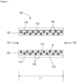
- a layered catalytic article 100 includes a substrate 110 coated with a catalyst 120, which is a washcoat including a mixture of copper on a molecular sieve material 130 and platinum and rhodium on a refractory metal oxide support 140.
- the substrate 110 has an inlet end 150 and an outlet end 160 defining an axial length L1.
- the substrate 110 generally comprises a plurality of channels 170 of a honeycomb substrate, of which only one channel is shown in cross-section for clarity.
- the length of the catalyst 120 on the substrate 110 can be varied, such that the catalyst 120 covers the entire substrate 110 or covers only a portion of the substrate 110.
- Embodiments of a second aspect of the present invention are directed to a catalyst for oxidizing ammonia, the catalyst comprising a first washcoat zone and a second washcoat zone, wherein the first washcoat zone includes copper or iron on a small pore molecular sieve material having a maximum ring size of eight tetrahedral atoms, the first washcoat zone being substantially free of platinum group metal; and the second washcoat zone includes copper or iron on a small pore molecular sieve material having a maximum ring size of eight tetrahedral atoms physically mixed with platinum and rhodium on a refractory metal oxide support including alumina, silica, zirconia, titania, and physical mixtures or chemical combinations thereof, including atomically doped combinations.
- the term "substantially free of platinum group metals” means that there is no platinum group metal intentionally added to the first washcoat zone, and that there is generally less than about 1 wt. %, including less than about 0.75 wt. %, less than about 0.5 wt. %, less than about 0.25 wt. %, and less than about 0.1 wt. %, of platinum group metal in the first washcoat zone. It will be appreciated by one of skill in the art, however, that during loading/coating trace amounts of platinum group metals may migrate from one washcoat zone component to another, such that trace amounts of platinum group metals can be present in the first washcoat zone.
- first washcoat zone and the second washcoat zone are arranged in an axially zoned configuration.
- axially zoned refers to the location of the first washcoat zone and the second washcoat relative to one another. Axially means side-by-side such that the first washcoat zone and the second washcoat zone are located one beside the other.
- first washcoat zone and second washcoat zone are disposed on a monolithic substrate.
- the first washcoat zone and the second washcoat zone are disposed on the same, or a common, substrate. In other embodiments the first washcoat zone and the second washcoat zone are disposed on separate substrates.
- the first washcoat zone is upstream from the second washcoat zone.
- upstream and downstream refer to relative directions according to the flow of an engine exhaust gas stream from an engine towards a tailpipe, with the engine in an upstream location and the tailpipe and any pollution abatement articles such as filters and catalysts being downstream from the engine.
- the second washcoat zone includes platinum and no other platinum group metal.
- the platinum loading is in the range of 0.01 g/l to 0.71 g/l, including 0.07 g/l to 0.71 g/l, 0.07 g/l to 0.35 g/l, and 0.07 g/l to 0.18 g/l (0.3 g/ft 3 to 20 g/ft 3 , including 2 g/ft 3 to 20 g/ft 3 , 2 g/ft 3 to 10 g/ft 3 and 2 g/ft 3 to 5 g/ft 3 ).
- the second washcoat zone includes platinum and further includes rhodium and no other platinum group metal.
- the platinum loading is in the range of 0.01 g/l to 0.71 g/l, including 0.07 g/l to 0.71 g/l, 0.07 g/l to 0.35 g/l, and 0.07 g/l to 0.18 g/l (0.3 g/ft 3 to 20 g/ft 3 , including 2 g/ft 3 to 20 g/ft 3 , 2 g/ft 3 to 10 g/ft3, and 2 g/ft 3 to 5 g/ft 3 ), and the rhodium loading is in the range of 0.01 g/l to 0.71 g/l, including 0.07 g/l to 0.35 g/l, and 0.07 g/l to 0.18 g/l (
- the amount of platinum present in the catalyst is greater than or equal to the amount of rhodium present in the catalyst.
- the ratio of Pt to Rh is equal to or greater than 1, including greater than about 1.5, greater than about 2, greater than about 5, greater than about 10, and greater than about 20.
- the molecular sieve material of the first washcoat zone and the second washcoat zone is a small pore molecular sieve material having a maximum ring size of eight tetrahedral atoms.
- the molecular sieve material of the first washcoat zone and/or the second washcoat zone is selected from framework types CHA, AEI, AFX, ERI, KFI, LEV, AFT, EAB, DDR, PAU, RHO, SAV, SAT, TSC, UEI and combinations thereof.
- the molecular sieve material of the first washcoat zone and/or the second washcoat zone has the CHA framework type.
- the refractory metal oxide support of the second washcoat zone includes alumina, silica, zirconia, titania, and physical mixtures or chemical combinations thereof, including atomically doped combinations.
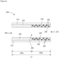
- FIGS. 2A and 2B Embodiments of a second aspect of the invention, where the catalyst is coated onto a substrate are illustrated in FIGS. 2A and 2B .
- FIG. 2A an exemplary embodiment of an axially zoned catalytic article is shown.
- the catalytic article 200 is shown in an axially zoned arrangement where a first washcoat zone 220 is located upstream of a second washcoat zone 230 on a substrate 210.
- the first washcoat zone 220 includes copper or iron on a molecular sieve.
- the second washcoat zone 230 includes a mixture of copper or iron on a molecular sieve material 240 and platinum and rhodium on a refractory metal oxide support 250.
- the substrate 210 has an inlet end 260 and an outlet end 270 defining an axial length L2.
- the substrate 210 generally comprises a plurality of channels 280 of a honeycomb substrate, of which only one channel is show in cross-section for clarity.
- the first washcoat zone 220 extends from the inlet end 260 of the substrate 210 through less than the entire axial length L2 of the substrate 210.
- the length of the first washcoat zone 220 is denoted as first washcoat zone length 2230a in FIG. 2 .
- the second washcoat zone 230 extends from the outlet end 270 of the substrate 210 through less than the entire axial length L2 of the substrate L2.
- the length of the second washcoat zone 230 is denoted as second washcoat zone length 230a in FIGs. 2A and 2B .
- the first washcoat zone 220 including copper or iron on a molecular sieve is directly abutting the second washcoat zone 230 including a mixture of copper or iron on a molecular sieve material 240 and platinum and rhodium on a refractory metal oxide support 250.
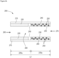
- the first washcoat zone 220 including copper or iron on a molecular sieve and the second washcoat zone 230 including a mixture of copper or iron on a molecular sieve material 240 and platinum and rhodium on a refractory metal oxide support 250 may be separated by a gap 290.
- the length of the first washcoat zone 220 and the second washcoat zone 230 can be varied.
- the first washcoat zone 220 and the second washcoat zone 230 can be equal in length.
- the first washcoat zone 220 can be in the range of about 10 to 90%, or about 20 to about 80% of the length L2 of the substrate 210, with the second washcoat zone 230 respectively covering the remainder of the length L2 of the substrate 210, as depicted in FIG. 2A .
- the first washcoat zone 220 can be about 10%, about 15%, about 20%, about 25%, about 30%, about 35%, about 40%, about 45%, about 50%, about 55%, about 60%, about 65%, about 70%, about 75%, about 80%, about 85%, or about 90% of the length L2 of the substrate 210, with the second washcoat zone 230 respectively covering the remainder of the length L2 of the substrate 210, with a gap 290, as depicted in FIG. 2B .
- first washcoat zone and second washcoat zone can be at least partially overlapping (not illustrated).
- at least partially overlapping means that the first washcoat zone and the second washcoat zone can overlap each other by an amount in the range of at least about 0.1% to at least about 99%.
- the first washcoat zone and second washcoat zone can be completely overlapping.
- the first washcoat zone is partially overlapping the second washcoat zone.
- the second washcoat zone is partially overlapping the first washcoat zone.
- the catalyst materials can be applied to a substrate as a washcoat.
- substrate refers to the monolithic material onto which the catalyst is placed, typically in the form of a washcoat.
- a washcoat is formed by preparing a slurry containing a specified solids content (e.g., 30-90% by weight) of catalyst in a liquid vehicle, which is then coated onto a substrate and dried to provide a washcoat layer.
- the substrate is a ceramic or metal having a honeycomb structure.
- Any suitable substrate may be employed, such as a monolithic substrate of the type having fine, parallel gas flow passages extending there through from an inlet or an outlet face of the substrate such that passages are open to fluid flow there through.
- the passages which are essentially straight paths from their fluid inlet to their fluid outlet, are defined by walls on which the catalytic material is coated as a washcoat so that the gases flowing through the passages contact the catalytic material.
- the flow passages of the monolithic substrate are thin-walled channels, which can be of any suitable cross-sectional shape and size such as trapezoidal, rectangular, square, sinusoidal, hexagonal, oval, circular, etc.
- Such structures may contain from about 9 to about 140 or more gas inlet openings (i.e. cells) per square cm of cross section (about 60 to about 900 or more gas inlet openings (i.e. cells) per square inch of cross section).
- the ceramic substrate may be made of any suitable refractory material, e.g. cordierite, cordierite- ⁇ -alumina, silicon nitride, zircon mullite, spodumene, alumina-silica-magnesia, zircon silicate, sillimanite, a magnesium silicate, zircon, petalite, ⁇ -alumina, an aluminosilicate and the like.
- suitable refractory material e.g. cordierite, cordierite- ⁇ -alumina, silicon nitride, zircon mullite, spodumene, alumina-silica-magnesia, zircon silicate, sillimanite, a magnesium silicate, zircon, petalite, ⁇ -alumina, an aluminosilicate and the like.
- the substrates useful for the catalyst of embodiments of the present invention may also be metallic in nature and be composed of one or more metals or metal alloys.
- the metallic substrates may be employed in various shapes such as pellets, corrugated sheet or monolithic form.
- Specific examples of metallic substrates include the heat-resistant, base-metal alloys, especially those in which iron is a substantial or major component.
- Such alloys may contain one or more of nickel, chromium, and aluminum, and the total of these metals may advantageously comprise at least about 15 wt. % of the alloy, for instance, about 10 to 25 wt. % chromium, about 1 to 8 wt. % of aluminum, and about 0 to 20 wt. % of nickel.
- the catalyst for oxidizing ammonia may be coated on a high porosity ceramic honeycomb flow through support.
- the high porosity ceramic honeycomb flow through support can have the following properties: a large fraction of interconnected pores; the porosity of wall material is greater than about 50 % and up to about 70% porosity; a mean pore size greater than 20 microns, for example, greater than 25 microns, more specifically greater than about 30 microns, and more particularly greater than about 40 microns but less than about 100 microns; and a broad pore size distribution.
- the catalyst for oxidizing ammonia of one or more embodiments may be coated on a wall-flow filter.
- a selective catalytic reduction article when coated on a wall-flow filter, the result is SCR on a Filter.
- the catalyst comprising a washcoat including copper or iron on a molecular sieve material mixed with platinum and rhodium on a refractory metal oxide support may be coated on a wall-flow filter.
- the first washcoat zone including copper or iron on a molecular sieve material having a maximum ring size of eight tetrahedral atoms is coated on a wall-flow filter, such as to produce SCR on a Filter
- the second washcoat zone including copper or iron on a molecular sieve material having a maximum ring size of eight tetrahedral atoms mixed with platinum and rhodium on a refractory metal oxide support including alumina, silica, zirconia, titania, and physical mixtures or chemical combinations thereof, including atomically doped combinations is coated on a flow through monolith.
- both the first washcoat zone and the second washcoat zone are coated on a wall-flow filter.
- the first washcoat zone and the second washcoat zone can be coated on a single wall-flow filter, or the first washcoat zone and the second washcoat zone can be coated on separate wall-flow filters so that two bricks are present in the exhaust gas treatment system.
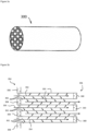
- FIGs. 3A and 3B illustrate a wall flow filter substrate 300 which has a plurality of passages 352.
- the passages are tubularly enclosed by the channel walls 353 of the filter substrate.
- the substrate has an inlet end 354 and an outlet end 356.
- Alternate passages are plugged at the inlet end with inlet plugs 358, and at the outlet end with outlet plugs 360 to form opposing checkerboard patterns at the inlet end 354 and outlet end 356.
- a gas stream 362 enters through the unplugged channel inlet 364, is stopped by outlet plug 360 and diffuses through channel walls 353 (which are porous) to the outlet side 366. The gas cannot pass back to the inlet side of walls because of inlet plugs 358.
- wall flow filter substrates are composed of ceramic-like materials such as cordierite, ⁇ -alumina, silicon carbide, silicon nitride, zirconia, mullite, spodumene, alumina-silica-magnesia or zirconium silicate, or of porous, refractory metal.
- wall flow substrates are formed of ceramic fiber composite materials.
- wall flow substrates are formed from cordierite and silicon carbide. Such materials are able to withstand the environment, particularly high temperatures, encountered in treating the exhaust streams.
- wall flow substrates include thin porous walled honeycombs monoliths through which the fluid stream passes without causing too great an increase in back pressure or pressure across the article. Normally, the presence of a clean wall flow article will create a back pressure of 249 Pa to 68950 Pa (1 inch water column to 10 psig). Ceramic wall flow substrates used in the system are formed of a material having a porosity of at least 50% (e.g., from 50 to 75%) having a mean pore size of at least 5 microns (e.g., from 5 to 30 microns). In one or more embodiments, the substrates have a porosity of at least 55% and have a mean pore size of at least 10 microns.
- Typical wall flow filters in commercial use are formed with lower wall porosities, e.g., from about 35% to 50%, than the wall flow filters utilized in the invention.
- the pore size distribution of commercial wall flow filters is typically very broad with a mean pore size smaller than 17 microns.
- the porous wall flow filter used in one or more embodiments is catalyzed in that the wall of said element has thereon or contained therein one or more catalytic materials.
- Catalytic materials may be present on the inlet side of the element wall alone, the outlet side alone, both the inlet and outlet sides, or the wall itself may consist all, or in part, of the catalytic material.
- This invention includes the use of one or more layers of catalytic materials and combinations of one or more layers of catalytic materials on the inlet and/or outlet walls of the element.
- the substrates are immersed vertically in a portion of the catalyst slurry such that the top of the substrate is located just above the surface of the slurry. In this manner slurry contacts the inlet face of each honeycomb wall, but is prevented from contacting the outlet face of each wall.
- the sample is left in the slurry for about 30 seconds.
- the substrate is removed from the slurry, and excess slurry is removed from the wall flow substrate first by allowing it to drain from the channels, then by blowing with compressed air (against the direction of slurry penetration ), and then by pulling a vacuum from the direction of slurry penetration.
- the catalyst slurry permeates the walls of the substrate, yet the pores are not occluded to the extent that undue back pressure will build up in the finished substrate.
- permeate when used to describe the dispersion of the catalyst slurry on the substrate, means that the catalyst composition is dispersed throughout the wall of the substrate.
- the coated substrates are dried typically at about 100 °C and calcined at a higher temperature (e.g., 300 to 450 °C). After calcining, the catalyst loading can be determined through calculation of the coated and uncoated weights of the substrate. As will be apparent to those of skill in the art, the catalyst loading can be modified by altering the solids content of the coating slurry. Alternatively, repeated immersions of the substrate in the coating slurry can be conducted, followed by removal of the excess slurry as described above.
- the NH 3 oxidation catalyst can be applied in washcoat layers, which are coated upon and adhered to the substrate.
- washcoat has its usual meaning in the art of a thin, adherent coating of a catalytic or other material applied to a substrate material, such as a honeycomb-type carrier member, which is sufficiently porous to permit the passage of the gas stream being treated.
- a washcoat layer of a composition containing an NH 3 oxidation catalyst may be formed by preparing a mixture or a solution of copper or iron on a molecular sieve material and a platinum precursor and/or a rhodium precursor in a suitable solvent, e.g. water.
- a suitable solvent e.g. water.
- aqueous solutions of soluble compounds or complexes of the platinum and/or rhodium are preferred.
- the platinum and/or rhodium precursor is utilized in the form of a compound or complex to achieve dispersion of the platinum precursor and/or rhodium precursor on the support.
- platinum precursor means any compound, complex, or the like which, upon calcination or initial phase of use thereof, decomposes or otherwise converts to a catalytically active form.
- Suitable platinum complexes or compounds include, but are not limited to platinum chlorides (e.g. salts of [PtCl 4 ] 2- , [PtCl 6 ] 2- ), platinum hydroxides (e.g. salts of [Pt(OH) 6 ] 2- ), platinum ammines (e.g.
- Suitable rhodium complexes or compounds include, but are not limited to rhodium chlorides, rhodium hydroxides, rhodium nitrates, and the like.
- a rhodium nitrate solution is used, which can be prepared by dissolution of Rh 2 O 3 in nitreous acid and may be denoted as dissolved Rh(NO 3 ) 3 .
- this invention is not restricted to rhodium precursors of a particular type, composition, or purity.
- a mixture or solution of the platinum and/or rhodium precursor is added to the support by one of several chemical means. These include impregnation of a solution of the platinum precursor and/or rhodium precursor onto the support, which may be followed by a fixation step incorporating acidic component (e.g. acetic acid) or a basic component (e.g. ammonium hydroxide). This wet solid can be chemically reduced or calcined or be used as is.
- the support may be suspended in a suitable vehicle (e.g. water) and reacted with the platinum precursor and/or rhodium precursor in solution. Additional processing steps may include fixation by an acidic component (e.g. acetic acid) or a basic component (e.g. ammonium hydroxide), chemical reduction, or calcination.
- the layer can contain a zeolitic or non-zeolitic molecular sieve on which has been distributed a metal selected from one or more of copper (Cu), iron (Fe), cobalt (Co), nickel (Ni), lanthanum (La), cerium (Ce), manganese (Mn), vanadium (V), or silver (Ag).
- a metal selected from one or more of copper (Cu), iron (Fe), cobalt (Co), nickel (Ni), lanthanum (La), cerium (Ce), manganese (Mn), vanadium (V), or silver (Ag).
- An exemplary metal of this series is copper.
- Exemplary molecular sieves include, but are not limited to zeolites having one of the following crystal structures CHA, AEI, AFX, ERI, KFI, LEV, AFT, EAB, DDR, PAU, RHO, SAV, SAT, TSC, UEI and combinations thereof.
- a suitable method for distributing the metal on the zeolite is to first prepare a mixture or a solution of the metal precursor in a suitable solvent, e.g. water.
- a suitable solvent e.g. water.
- aqueous solutions of soluble compounds or complexes of the metal are preferred.
- the term "metal precursor" means any compound, complex, or the like which can be dispersed on the zeolite support to give a catalytically-active metal component.
- suitable complexes or compounds include, but are not limited to anhydrous and hydrated copper sulfate, copper nitrate, copper acetate, copper acetylacetonate, copper oxide, copper hydroxide, and salts of copper ammines (e.g. [Cu(NH 3 ) 4 ] 2+ ).
- this invention is not restricted to metal precursors of a particular type, composition, or purity.
- the molecular sieve can be added to the solution of the metal component to form a suspension. This suspension can be allowed to react so that the copper component is distributed on the zeolite. This may result in copper being distributed in the pore channels as well as on the outer surface of the molecular sieve.
- Copper may be distributed as copper (II) ions, copper (I) ions, or as copper oxide. After the copper is distributed on the molecular sieve, the solids can be separated from the liquid phase of the suspension, washed, and dried. The resulting copper-containing molecular sieve may also be calcined to fix the copper.
- finely divided particles of a catalyst including the SCR component, the NH 3 oxidation catalyst, or a mixture thereof, are suspended in an appropriate vehicle, e.g., water, to form a slurry.
- an appropriate vehicle e.g., water
- Other promoters and/or stabilizers and/or surfactants may be added to the slurry as mixtures or solutions in water or a water-miscible vehicle.
- the slurry is comminuted/milled to result in substantially all of the solids having particle sizes of less than about 10 microns, i.e., in the range of about 0.1-8 microns, in an average diameter.
- the suspension or slurry has a pH of about 2 to less than about 7.
- the pH of the slurry may be adjusted if necessary by the addition of an adequate amount of an inorganic or an organic acid to the slurry.
- the solids content of the slurry may be, e.g., about 20-60 wt. %, and more particularly about 35-45 wt. %.
- the substrate may then be dipped into the slurry, or the slurry otherwise may be coated on the substrate, such that there will be deposited on the substrate a desired loading of the catalyst layer.
- the coated substrate is dried at about 100 °C and calcined by heating, e.g., at 300-650 °C for about 1 to about 3 hours. Drying and calcination are typically done in air. The coating, drying, and calcination processes may be repeated if necessary to achieve the final desired gravimetric amount of the catalyst washcoat layer on the support. In some cases, the complete removal of the liquid and other volatile components may not occur until the catalyst is placed into use and subjected to the high temperatures encountered during operation.
- the catalyst washcoat loading can determined through calculation of the difference in coated and uncoated weights of the substrate.
- the catalyst loading can be modified by altering the solids content of the coating slurry and slurry viscosity. Alternatively, repeated immersions of the substrate in the coating slurry can be conducted, followed by removal of the excess slurry as described above.
- Another aspect of the present invention includes a method of treating emissions produced in the exhaust gas stream of a lean-burn engine.
- the exhaust gas stream can include one or more of NO x , CO, hydrocarbons, and ammonia.
- the method includes injecting ammonia or an ammonia precursor into an exhaust gas stream containing one or more of NOx, CO, or hydrocarbons and then passing the exhaust gas stream through the catalyst of one or more embodiments of the present invention.
- Diesel engine exhaust is a heterogeneous mixture which contains not only gaseous emissions such as carbon monoxide, unburned hydrocarbons and NO x , but also condensed phase materials (liquids and solids) which constitute the particulates or particulate matter.
- catalyst compositions and substrates on which the compositions are disposed are provided in diesel engine exhaust systems to convert certain or all of these exhaust components to innocuous components.
- diesel exhaust systems can contain one or more of a diesel oxidation catalyst and a soot filter, in addition to a catalyst for the reduction of NO x .
- Embodiments of the present invention can be incorporated into diesel exhaust gas treatment systems.
- One such system is disclosed in U.S. Patent No. 7,229,597 .
- FIG. 4 depicts a schematic representation of an emission treatment system 400, in accordance with one or more embodiments of the present invention.
- An exhaust gas stream containing gaseous pollutants e.g., unburned hydrocarbons, carbon monoxide and NO x
- gaseous pollutants e.g., unburned hydrocarbons, carbon monoxide and NO x
- particulate matter is conveyed via line 415 from an engine 410 to a diesel oxidation catalyst (DOC) 420.
- DOC diesel oxidation catalyst
- unburned gaseous and non-volatile hydrocarbons and carbon monoxide are largely combusted to form carbon dioxide and water.
- a proportion of the NO of the NO x component may be oxidized to NO 2 in the DOC.
- the exhaust stream is next conveyed via line 425 to a catalyzed soot filter (CSF) 430, which traps particulate matter present within the exhaust gas stream.
- CSF catalyzed soot filter
- the CSF is optionally catalyzed for passive regeneration.
- the exhaust gas stream is conveyed via line 435 to a downstream catalyst 440.
- the downstream catalyst 440 may be the catalyst according to one or more embodiments described herein, for the treatment and/or conversion of NO x and ammonia.
- the downstream catalyst 440 may be a SCR catalyst.
- the exhaust gas treatment system includes one or more of a urea storage tank, a urea pump, a urea dosing system, a urea injector/nozzle, and a respective control unit 455 upstream from the SCR catalyst 440 for injecting a source of ammonia into the exhaust gas stream.
- the exhaust gas treatment system may also include an ammonia oxidation catalyst 450 downstream from the SCR catalyst 440 via line 445.
- the ammonia oxidation catalyst 450 may be a catalyst according to one or more embodiments described herein.
- a zirconia acetate solution (1.3 kg) was mixed with deionized water (9 kg) in a container.
- Cu-SSZ-13 with 3 wt. % CuO (8.6 kg) was added to this mixture to form a dispersion, and the resulting dispersion was milled with a ball mill until a particle size measurement resulted in a particle size distribution of 90% of the particle smaller than 5 microns.
- alumina powder (716 g) that was doped with 20 wt. % zirconia was added into deionized water (4.5 Kg) containing tartaric acid (13 mg) and monoethanolamine (5 mg). The pH of the mixture was adjusted to 4 with tartaric acid. Afterwards, the mixture was milled with a ball mill to obtain a particle size distribution of 90% of the particles smaller than 10 micron.
- a solution of zirconia acetate (1.3 Kg) was mixed with deionized water (9 Kg) in a container.
- deionized water 9 Kg
- Cu-SSZ-13 3 wt. % CuO (8.6 Kg)
- the resulting dispersion was milled with a ball mill until a particle size measurement resulted in a particle size distribution of 90% of the particles smaller than 5 microns.
- a solution of platinum monoethanol (45 g) with 17 wt. % Pt was mixed with deionized water (100 mL). This mixture was added dropwise onto an alumina powder that was doped with 20 wt. % zirconia (716 g). The resulting powder was then calcined in a box oven for 2 h at 600 °C under air. The calcined powder was added into deionized water (4.5 kg) that contained tartaric acid (13 mg) and monoethanolamine (5 mg). The pH of the mixture was adjusted to 4 with tartaric acid. Afterwards, the mixture was milled with a ball mill to obtain a particle size distribution of 90% of the particle smaller than 10 micron.
- the resulting slurry was coated onto a ceramic honeycomb substrate to obtain a loading of 198 g/l (3.25 g/in 3 ) after calcination for 2 h at 600 °C.
- the Amox with Pt, Pt/Rh on Zr doped alumina has 198 g/l (3,25 g/inch 3 ) loading
- a zone catalyst was prepared from the slurries from Comparative Example 1 and Comparative Example 2 in the following way: The slurry from Comparative Example 1 was coated to 50% on the inlet part of a honeycomb, and the platinum containing slurry of Comparative Example 2 was coated on the remaining 50% of the rear zone of the honeycomb. In this way, the platinum was located only in 50% of the rear of the honeycomb.
- a solution of zirconia acetate (1.3 kg) was mixed with deionized water (9 kg) in a container.
- deionized water 9 kg
- Cu-SSZ-13 3 wt. % CuO (8.6 kg)
- the resulting dispersion was milled with a ball mill until a particle size measurement resulted in a particle size distribution of 90% of the particles smaller than 5 microns.
- a solution of platinum monoethanol (10 g) with 17 wt. % Pt was mixed with deionized water (100 mL). This mixture was added dropwise onto an Alumina powder (716 g) that was doped with 20 wt. % zirconia. Subsequently a solution of rhodium-nitrate (33 mL) with 10 wt. % of Rh was added dropwise onto the platinum alumina powder. The resulting powder was then calcined in a box oven for 2 h at 600 °C under air. The calcined powder was added into deionized water (4.5 kg) that contained tartaric acid (13 mg) and monoethanolamine (5 mg). The pH of the mixture was adjusted to 4 with tartaric acid. Afterwards, the mixture was milled with a ball mill to obtain a particle size distribution of 90% of the particle smaller than 10 micron.
- a solution of zirconia acetate (1.3 kg) was mixed with deionized water (9 kg) in a container.
- deionized water 9 kg
- Cu-SSZ-13 3 wt. % CuO (8.6 kg)
- the resulting dispersion was milled with a ball mill until a particle size measurement resulted in a particle size distribution of 90% of the particle smaller than 5 microns.
- a solution of rhodium-nitrate (85 g) with 9 wt. % Rh was mixed with deionized water (100 mL). This mixture was added dropwise onto an alumina powder (716 g) that was doped with 20 wt. % zirconia. The resulting powder was than calcined in a box oven for 2 h at 600 °C under air. The calcined powder was added into deionized water (4.5 kg) that contained tartaric acid (13 mg) and monoethanolamine (5 mg). The pH of the mixture was adjusted to 4 with tartaric acid. Afterwards, the mixture was milled with a ball mill to obtain a particle size distribution of 90% of the particle smaller than 10 micron.
- the resulting slurry was coated onto a ceramic honeycomb substrate to obtain a loading of 198 g/l (3.25 g/in 3 ) after calcination for 2 h at 600 °C.
- a solution of zirconia acetate (1.3 kg) was mixed with deionized water (9 kg) in a container.
- deionized water 9 kg
- Cu-SSZ-13 3 wt. % CuO (8.6 kg)
- the resulting dispersion was milled with a ball mill until a particle size measurement resulted in a particle size distribution of 90% of the particles smaller than 5 microns.
- a solution of platinum monoethanolamine (26 g) with 17 wt. % Pt was mixed with deionized water (100 mL). This mixture was added dropwise onto an alumina powder (716 g) that was doped with 20 wt. % zirconia. Subsequently a solution of palladium-nitrate (15 mL) with 20 wt. % of Pd was added dropwise onto the platinum alumina powder. The resulting powder was then calcined in a box oven for 2 h at 600 °C under air. The calcined powder was added into deionized water (4.5 kg) that contained tartaric acid (13 mg) and monoethanolamine (5 mg). The pH of the mixture was adjusted to 4 with tartaric acid. Afterwards, the mixture was milled with a ball mill to obtain a particle size distribution of 90% of the particle smaller than 10 micron.
- the resulting slurry was coated onto a ceramic honeycomb substrate to obtain a loading of 198 g/l (3.25 g/in 3 ) after calcination for 2 h at 600 °C.
- First slurry A solution of platinum monoethanol (330 g) with 17 wt. % Pt was mixed with deionized water (100 mL). This mixture was added dropwise onto an alumina powder (716 g) that was doped with 1.5 wt. % silica. To this powder was added water (800 mL) and glacial acetic acid (450 g). Subsequently, this powder was put into deionized water (4.5 kg) and milled at pH 4 with a ball mill to obtain a particle size distribution of 90% of the particle smaller than 7.5 micron.
- the resulting slurry was coated onto a ceramic honeycomb substrate to obtain a covering of 40% of the rear zone of the honeycomb.
- the loading of the coating was 12 g/l (0.2 g/in 3 ) after calcination for 2 h at 600 °C.
- Second slurry A solution of zirconia acetate (1.3 kg) was mixed with deionized water (9 kg) in a container. To this mixture was added Cu-SSZ-13 with 3 wt. % CuO (8.6 kg), and the resulting dispersion was milled with a ball mill until a particle size measurement resulted in a particle size distribution of 90% of the particle smaller than 5 microns.
- the resulting slurry was coated onto a ceramic honeycomb substrate to obtain a loading of 174 g/l (2.85 g/in 3 ) after calcination for 2 h at 600 °C.
- a zirconia acetate solution (1.3 kg) was mixed with deionized water (9 kg) in a container.
- Cu-SSZ-13 with 3 wt. % CuO (8.6 kg) was added to this mixture to form a dispersion, and the resulting dispersion was milled with a ball mill until a particle size measurement resulted in a particle size distribution of 90% of the particle smaller than 5 microns.
- the resulting slurry was coated onto a ceramic honeycomb substrate to obtain a loading of 183 g/l (3 g/in 3 ) after calcination for 2 h at 600 °C.
- Table 1 summarizes the formulations of the catalysts Table 1 Ex. # Pt (g/l) Rh (g/l) Pd (g/l) Cu-CHA (g/L) Zirconium Acetate (g/L) PGM Support Feature Comp. Ex. 1 - - - 2.85 9 alumina doped with 20% zirconia No PGM Comp. Ex. 2 0.18 (5 g/ft 3 ) - - 2.85 9 alumina doped with 20% zirconia PGM/support is mixed into zeolite coating Comp. Ex. 3 0.09 (2.5 g/ft 3 ) - - 2.85 9 alumina doped with 20% zirconia PGM/support covers 50% in the outlet of the monolith Ex.
- the SCR activity was tested under steady state engine operation conditions after aging for 16 h under hydrothermal conditions (10% H 2 O with 10% O 2 and 80% N 2 ). For this test the engine was tuned to achieve a desired exhaust gas temperature at NO x emission of 250-300 ppm. If a constant temperature was achieved, urea was injected after the DOC/filter canning. The urea amount was adjusted to achieve a NH 3 to NO x ratio of 1.2 and was maintained for 10 min after 20 ppm NH 3 was measured after the catalyst. After stopping the urea dosing, the measurement was prolonged until the NO x conversion was decrease to less than 5% conversion.
- Table 2 shows the arrangements of the catalyst for the stationary engine bench evaluation.
- Catalyst PGM (g/l) Volume (L) Dimensions (cm*cm) cells/wall thickness (cells/cm) 1 DOC 4.2 (120 g/ft 3 ) 1.24 14.4*7.6
- Pt:Pd 1:1 (5.66 inch*3 inch) 263/1 (400/6 cells/mil) 2 CSF 1.5 (43 g/ft 3 ) 2.44 SiC, 14.4*15.2
- Pt:Pd 3:1 (5.66 inch*6 inch) 98/1 (300/12 cells/mil) 3 SCR(AMOx) 0 1.54 14.4*11,4 (5.66 inch*4.5 inch) 394/1 (400/4 cells/mil)
- Table 3 shows the engine operation points and the exhaust gas conditions for the stationary bench evaluation.
- Table 3 Engine Operation Conditions At SCR Test, Standard Inlet Gas Temp. (°C) Inlet NO x Conc. (ppm) Inlet CO Conc. (ppm) Inlet HC Conc. (ppm) Alpha VL (m 3 /h) Urea Flow (mg/s) 200 241 2 17 2 92 49 230 217 2 11 1.1 94 27 360 264 3 2 1.1 177 58 650 351 121 228 1.5 220 135
- Table 4 shows the rest results of the stationary engine bench evaluation.
- Table 4 Ex. # Temp. Out (°C) NO x Conv. (%) N 2 O Emissions at 20 ppm NH 3 slip (ppm) NH 3 /NO x Ratio NH 3 Emissions at Full NO x Conv. (ppm)
- Example 5 that contains Rh only had the same NO x conversion as Example 1, and, therefore, Rh behaved inert to the selective NO x reduction.
- the Pt only sample (Example 3) had the lowest NO x conversion at higher temperature and higher N 2 O formation.
- Negative NO x conversions at 650 °C mean that NH 3 feed converted to undesired NO x at a high rate.
- Example 4 The Pt and Rh containing sample (Example 4), however, had lower N 2 O formation compared to the zoned Example 7 sample and the same NO x conversion at 370 °C. The result shows that the addition of Rh to Pt lowers the N 2 O formation and a high NH 3 oxidation rate is maintained.
- the Artemis test was performed with a 2 L EU 6 engine with a system consisting of a DOC, SCR on a filter close coupled to the engine, and an AMOx-SCR catalyst in a position 1.5 meter downstream of the engine. All AMOx catalysts were hydrothermally aged (10% H 2 O with 10% O 2 and 80% N 2 ) for 16 h at 750 °C in an oven prior to the measurement.
- Table 6 shows the catalyst arrangement for the Artemis test at the engine bench.
- the urea was dosed into the exhausted system after the DOC to achieve a NH 3 to NO x ratio of 1.06.
- Table 7 shows the emission results with the different AMOx catalysts used in the system.
- Table 7 AMOx Catalyst NO x Engine Out (g/Km) NO x (g/Km) NH 3 (g/Km) N 2 O (g/Km) Average Inlet Temp. (°C) Ex. 1 0.313 0.087 0.027 0.010 180 Ex. 4 0.314 0.103 0.000 0.013 180 Ex. 5 0.314 0.119 0.000 0.014 180 Ex. 7 0.305 0.105 0.000 0.015 180
- Example 1 without PGM. In this case, however, ammonia emissions are difficult to avoid. All Pt containing samples completely avoided NH 3 emissions, and the sample with the lowest N 2 O and lowest NO x emissions among these samples was the Pt/Rh containing sample (Example 4). Example 7 resulted in higher N 2 O emissions.
- laboratory tests were conducted that simulated the dynamic Artemis test protocol with an NO only feed to simulate the conditions in an exhaust manifold after a soot filter with Cu-zeolite coating (SCR on a filter) in the underbody positions of a 2L VW EU 6 Engine.
- a very effective ammonia oxidation catalyst was prepared by mixing Pt/Rh supported on a doped gamma alumina material with a Cu-CHA zeolite for selective catalytic reduction of NO x with ammonia. The mixing was performed in a way that the Pt/Rh/doped alumina was spatially separated from the zeolite material.
- the Pt and Rh did not migrate to the zeolite particles and remained located on the doped alumina particles.
- the Cu migrated to the doped alumina particles in a way that there was the same or slightly higher Cu concentration found on the doped alumina particles as found on the zeolite particles.
- the Rh formed an alloy with the Pt and thus lowered the reaction rate for NO 2 and N 2 O formation strongly.
- This design allowed the application of a higher Pt concentration compared to Comparative Example 7 (according to WO2010/012730 ), and, thus, enabled implementation of a higher ammonia oxidation rate.
- the homogeneous design (Example 4) has an advantage over the layered design of Comparative Example 7 because nitrogen oxides formed on Pt can react with ammonia absorbed in the close vicinity of the doped alumina particles to form the desired N 2 . In this way a high selectivity for N 2 formation can be achieved, even at very high ammonia or urea dosing rates.
- the Artemis test was performed with a 2 L EU 6 engine with a system consisting of a DOC, SCR on a filter close coupled to the engine, and an AMOx-SCR catalyst in a position 1.5 meter downstream of the engine. All AMOx catalysts were hydrothermally aged (10% H 2 O with 10% O 2 and 80% N 2 ) for 16 h at 750 °C in an oven prior to the measurement.
- the maximum NO x engine out concentration was 1500 ppm, the average NO x concentration was 145 ppm.
- the maximum AMOx inlet (SCR on a filter out) concentration was 1100 ppm, the average NO x concentration was 50 ppm.
- the maximum AMOx space velocity was 150,000 h -1 , the average space velocity was 32 000 h -1 .
- the maximum AMOx inlet temperature was 420 °C, and the average temperature was 192 °C.
- Table 9 shows the NO x emissions in g/Km before the DOC and after the DOC plus SCR on a filter system. Furthermore, the quantity of NO x reduced over the underfloor AMOx catalyst is given in g/Km, as well as the N 2 O and NH 3 emissions downstream of the AMOx catalyst. The highest value for the quantity of NO x removed over the AMOx indicates the best results.
- Table 9 AMOx Catalyst NO x Engine Out (g/Km) NO x SCR on Filter Out (g/Km) NO x Removed Over AMOx (g/Km) N 2 O System Emissions (g/Km) NH 3 System Emissions (g/Km) Comp. Ex.
- the Comparative Example 1 catalyst without PGM provides the best NO x reduction and lowest N 2 O emissions, but does not remove the undesired NH 3 emissions.
- Pt in the homogeneous AMOx design can be alloyed with Pd or Rh.
- Comparative Example 5 shows the result with Pd and Comparative Example 6 with Rh.
- the catalyst with Rh (Example 4) achieves lower N 2 O and NH 3 emissions and it is, therefore, beneficial to use Rh.
- the advantage of using Rh becomes evident, since the Rh containing catalyst achieves the lowest NH 3 and N 2 O emissions at a high NO x conversion efficiency.
- the maximum space velocity was 180,000 h -1
- the average space velocity was 54,000 h -1 .
- the maximum NO x emissions were 580 ppm
- the average NO x emissions were 80 ppm.
- the cores were aged for 16 h at 750 °C with 10% steam in air. The evaluation was done without preconditioning with a typical H 2 O and CO 2 concentration, but without hydrocarbon and carbon monoxide present in the feed gas.
- Table 11 shows the NO x emissions in g/Km.
- Table 11 AMOx Catalyst NO x Inlet (g/(L*Km)) NO x Outlet (g/(L*Km)) NH 3 Feed (g/(L*Km)) NH 3 Outlet (g/(L*Km)) N 2 O Outlet (g/(L*Km)) Comp.
- 1 0.692 0.165 0.276 0.054 0.011
- 2 0.697 0.278 0.278 0.002 0.098
- 4 0.689 0.232 0.277 0.003 0.052
- Comp. Ex. 5 0.696 0.167 0.276 0.059 0.011
- Comp. Ex. 6 0.688 0.212 0.277 0.083 0.015
Landscapes
- Chemical & Material Sciences (AREA)
- Engineering & Computer Science (AREA)
- Chemical Kinetics & Catalysis (AREA)
- Organic Chemistry (AREA)
- Materials Engineering (AREA)
- Combustion & Propulsion (AREA)
- Health & Medical Sciences (AREA)
- Oil, Petroleum & Natural Gas (AREA)
- General Chemical & Material Sciences (AREA)
- Analytical Chemistry (AREA)
- Environmental & Geological Engineering (AREA)
- Biomedical Technology (AREA)
- Crystallography & Structural Chemistry (AREA)
- Toxicology (AREA)
- Mechanical Engineering (AREA)
- General Engineering & Computer Science (AREA)
- Exhaust Gas Treatment By Means Of Catalyst (AREA)
- Catalysts (AREA)
- Exhaust Gas After Treatment (AREA)
Applications Claiming Priority (2)
| Application Number | Priority Date | Filing Date | Title |
|---|---|---|---|
| EP15183947 | 2015-09-04 | ||
| PCT/EP2016/070292 WO2017037006A1 (en) | 2015-09-04 | 2016-08-29 | Integrated scr and ammonia oxidation catalyst systems |
Publications (2)
| Publication Number | Publication Date |
|---|---|
| EP3344384A1 EP3344384A1 (en) | 2018-07-11 |
| EP3344384B1 true EP3344384B1 (en) | 2025-03-26 |
Family
ID=54065745
Family Applications (1)
| Application Number | Title | Priority Date | Filing Date |
|---|---|---|---|
| EP16757666.9A Active EP3344384B1 (en) | 2015-09-04 | 2016-08-29 | Integrated scr and ammonia oxidation catalyst systems |
Country Status (9)
| Country | Link |
|---|---|
| US (1) | US11213789B2 (enExample) |
| EP (1) | EP3344384B1 (enExample) |
| JP (1) | JP6885927B2 (enExample) |
| KR (1) | KR102593060B1 (enExample) |
| CN (1) | CN107949436B (enExample) |
| CA (1) | CA2997040A1 (enExample) |
| MX (1) | MX2018002701A (enExample) |
| RU (1) | RU2018111984A (enExample) |
| WO (1) | WO2017037006A1 (enExample) |
Families Citing this family (25)
| Publication number | Priority date | Publication date | Assignee | Title |
|---|---|---|---|---|
| RU2770069C2 (ru) | 2017-03-29 | 2022-04-14 | Джонсон Мэтти Паблик Лимитед Компани | Катализатор предотвращения проскока аммиака (asc) с металлом платиновой группы в множестве слоев |
| US10828623B2 (en) * | 2018-05-18 | 2020-11-10 | Umicore Ag & Co. Kg | Hydrocarbon trap catalyst |
| US10850264B2 (en) * | 2018-05-18 | 2020-12-01 | Umicore Ag & Co. Kg | Hydrocarbon trap catalyst |
| WO2019223761A1 (en) * | 2018-05-25 | 2019-11-28 | Basf Se | Rare earth element containing aluminum-rich zeolitic material |
| CN108722477B (zh) * | 2018-06-06 | 2021-01-15 | 中国科学院过程工程研究所 | 一种抗碱中毒高效脱硝催化剂及其制备方法和应用 |
| CN112638526B (zh) * | 2018-08-22 | 2024-01-05 | 巴斯夫公司 | 先进的nox还原催化剂 |
| JP7555819B2 (ja) * | 2018-10-23 | 2024-09-25 | エヌ・イーケムキャット株式会社 | Cu-P共担持ゼオライト、並びに、これを用いた選択的還元触媒及び排ガス用触媒 |
| CN112955255B (zh) * | 2018-10-30 | 2023-07-21 | 巴斯夫公司 | 在预交换铜沸石材料上的原位铜离子交换 |
| CN112955256B (zh) * | 2018-10-30 | 2024-04-19 | 巴斯夫公司 | 位于过滤器基材上的选择性催化还原催化剂 |
| CN111219236A (zh) * | 2018-11-23 | 2020-06-02 | 汪利峰 | 柴油机尾气的后处理系统 |
| US10669908B1 (en) | 2018-12-03 | 2020-06-02 | Wellhead Power Solutions, Llc | Power generating systems and methods for reducing startup NOx emissions in fossile fueled power generation system |
| US11786887B2 (en) * | 2018-12-06 | 2023-10-17 | Basf Se | Aqueous suspension comprising a zeolitic material and a zirconium chelate complex |
| CN114072223B (zh) * | 2019-03-11 | 2024-05-24 | 印度商宜诺摩托克普有限公司 | 用于处理机动车排气的催化剂系统及其制造方法 |
| BR112021021118A2 (pt) | 2019-05-21 | 2021-12-14 | Basf Corp | Catalisador de oxidação de amônia, processo para a preparação do catalisador de oxidação de amônia e método para oxidar amônia |
| CN110237858A (zh) * | 2019-06-25 | 2019-09-17 | 无锡威孚环保催化剂有限公司 | 复合结构分子筛催化剂及其制备方法 |
| EP3782726A1 (en) * | 2019-08-20 | 2021-02-24 | Umicore Ag & Co. Kg | Catalyst for the abatement of ammonia and nitrogen oxide emissions from the exhaust gases of combustion engines |
| EP3782727A1 (de) * | 2019-08-20 | 2021-02-24 | Umicore Ag & Co. Kg | Katalysator zur reduzierung von ammoniak-emissionen |
| CN112412588A (zh) * | 2019-08-20 | 2021-02-26 | 汪利峰 | 柴油机尾气后处理催化剂单元 |
| KR102218996B1 (ko) * | 2019-09-23 | 2021-02-22 | 희성촉매 주식회사 | 지지체에 망간이 도핑된 산화 촉매조성물 |
| JP7725496B2 (ja) * | 2020-04-01 | 2025-08-19 | ビーエーエスエフ モバイル エミッションズ カタリスツ エルエルシー | 高アンモニア貯蔵能scr触媒 |
| US20240024819A1 (en) | 2020-12-14 | 2024-01-25 | Umicore Ag & Co. Kg | Catalytic Devices for the Abatement of NH3 and Nox Emissions From Internal Combustion Engines |
| CN112675901B (zh) * | 2020-12-29 | 2023-06-20 | 惠州市瑞合环保科技有限公司 | 用于柴油机尾气处理的scr催化剂及其制备方法和应用 |
| KR20230147151A (ko) * | 2021-02-17 | 2023-10-20 | 바스프 코포레이션 | 암모니아 산화 촉매 및 이의 제조 방법 |
| US11986802B2 (en) | 2021-08-31 | 2024-05-21 | Johnson Matthey Public Limited Company | Transition metal incorporated alumina for improved three way catalysts |
| EP4414054A1 (en) * | 2023-02-09 | 2024-08-14 | Johnson Matthey Public Limited Company | Transition metal incorporated alumina for improved three way catalysts |
Family Cites Families (29)
| Publication number | Priority date | Publication date | Assignee | Title |
|---|---|---|---|---|
| US1927963A (en) * | 1932-08-18 | 1933-09-26 | Grasselli Chemical Co | Catalyst for ammonia oxidation |
| GB868846A (en) | 1957-08-26 | 1961-05-25 | Union Carbide Corp | Improvements in and relating to zeolites |
| US3030181A (en) | 1957-08-26 | 1962-04-17 | Union Carbide Corp | Crystalline zeolite r |
| YU195874A (en) * | 1973-08-17 | 1982-05-31 | Degussa | Catalyst for the oxidation of ammonia |
| US4329162A (en) | 1980-07-03 | 1982-05-11 | Corning Glass Works | Diesel particulate trap |
| US4544538A (en) | 1982-07-09 | 1985-10-01 | Chevron Research Company | Zeolite SSZ-13 and its method of preparation |
| US4440871A (en) | 1982-07-26 | 1984-04-03 | Union Carbide Corporation | Crystalline silicoaluminophosphates |
| US6162415A (en) | 1997-10-14 | 2000-12-19 | Exxon Chemical Patents Inc. | Synthesis of SAPO-44 |
| ID28170A (id) | 1998-07-29 | 2001-05-10 | Exxon Chemical Patents Inc | Proses untuk pembuatan ayakan molekul |
| US7229597B2 (en) | 2003-08-05 | 2007-06-12 | Basfd Catalysts Llc | Catalyzed SCR filter and emission treatment system |
| US20100166628A1 (en) | 2006-02-15 | 2010-07-01 | Nicola Soeger | Catalyst for reducing nitrogen-containing pollutants from the exhaust gases of diesel engines |
| CN101454065A (zh) * | 2006-05-31 | 2009-06-10 | 尤米科尔股份公司及两合公司 | 降低柴油发动机废气中含氮污染气体的催化剂 |
| WO2008106523A2 (en) | 2007-02-27 | 2008-09-04 | Basf Catalysts Llc | Bifunctional catalysts for selective ammonia oxidation |
| US7815289B2 (en) * | 2007-08-31 | 2010-10-19 | Lexmark International, Inc. | Micro-fluid ejection heads and methods for bonding substrates to supports |
| US7821942B2 (en) | 2008-08-01 | 2010-10-26 | International Business Machines Corporation | Controlling data flow through a data communications link |
| US8524185B2 (en) | 2008-11-03 | 2013-09-03 | Basf Corporation | Integrated SCR and AMOx catalyst systems |
| DE102008055890A1 (de) * | 2008-11-05 | 2010-05-12 | Süd-Chemie AG | Partikelminderung mit kombiniertem SCR- und NH3-Schlupf-Katalysator |
| US8293182B2 (en) | 2010-05-05 | 2012-10-23 | Basf Corporation | Integrated SCR and AMOx catalyst systems |
| US20110286900A1 (en) | 2010-05-21 | 2011-11-24 | Basf Corporation | PGM-Zoned Catalyst for Selective Oxidation of Ammonia in Diesel Systems |
| RU2614411C2 (ru) | 2010-12-02 | 2017-03-28 | Джонсон Мэтти Паблик Лимитед Компани | Цеолитный катализатор, содержащий металл |
| GB201021887D0 (en) * | 2010-12-21 | 2011-02-02 | Johnson Matthey Plc | Oxidation catalyst for a lean burn internal combustion engine |
| US8722000B2 (en) * | 2011-03-29 | 2014-05-13 | Basf Corporation | Multi-component filters for emissions control |
| EP2692437B1 (en) * | 2011-03-31 | 2023-09-20 | N.E. Chemcat Corporation | Ammonia oxidation catalyst, exhaust gas purification device using same, and exhaust gas purification method |
| US8101146B2 (en) | 2011-04-08 | 2012-01-24 | Johnson Matthey Public Limited Company | Catalysts for the reduction of ammonia emission from rich-burn exhaust |
| JP6469578B2 (ja) * | 2012-10-19 | 2019-02-13 | ビーエーエスエフ コーポレーション | 混合金属8員環小孔分子ふるい触媒組成物、触媒製品、システム及び方法 |
| BR112015011998A2 (pt) * | 2012-11-30 | 2017-07-11 | Johnson Matthey Plc | artigo catalisador, método e sistema para o tratamento de um gás de emissão, e, método para preparar um artigo catalisador |
| US9511355B2 (en) * | 2013-11-26 | 2016-12-06 | Clean Diesel Technologies, Inc. (Cdti) | System and methods for using synergized PGM as a three-way catalyst |
| JP6239305B2 (ja) * | 2013-07-31 | 2017-11-29 | イビデン株式会社 | ハニカムフィルタ |
| JP5888312B2 (ja) | 2013-11-29 | 2016-03-22 | トヨタ自動車株式会社 | 排ガス浄化用触媒 |
-
2016
- 2016-08-29 CN CN201680050901.9A patent/CN107949436B/zh active Active
- 2016-08-29 WO PCT/EP2016/070292 patent/WO2017037006A1/en not_active Ceased
- 2016-08-29 CA CA2997040A patent/CA2997040A1/en not_active Abandoned
- 2016-08-29 EP EP16757666.9A patent/EP3344384B1/en active Active
- 2016-08-29 US US15/757,384 patent/US11213789B2/en active Active
- 2016-08-29 JP JP2018512135A patent/JP6885927B2/ja active Active
- 2016-08-29 KR KR1020187009265A patent/KR102593060B1/ko active Active
- 2016-08-29 RU RU2018111984A patent/RU2018111984A/ru not_active Application Discontinuation
- 2016-08-29 MX MX2018002701A patent/MX2018002701A/es unknown
Also Published As
| Publication number | Publication date |
|---|---|
| CN107949436A (zh) | 2018-04-20 |
| CA2997040A1 (en) | 2017-03-09 |
| RU2018111984A3 (enExample) | 2020-01-20 |
| MX2018002701A (es) | 2018-04-13 |
| US20190022584A1 (en) | 2019-01-24 |
| KR102593060B1 (ko) | 2023-10-25 |
| CN107949436B (zh) | 2021-11-12 |
| EP3344384A1 (en) | 2018-07-11 |
| JP2018534126A (ja) | 2018-11-22 |
| JP6885927B2 (ja) | 2021-06-16 |
| US11213789B2 (en) | 2022-01-04 |
| KR20180050687A (ko) | 2018-05-15 |
| RU2018111984A (ru) | 2019-10-04 |
| WO2017037006A1 (en) | 2017-03-09 |
Similar Documents
| Publication | Publication Date | Title |
|---|---|---|
| EP3344384B1 (en) | Integrated scr and ammonia oxidation catalyst systems | |
| US10792648B2 (en) | Mixed metal large crystal molecular sieve catalyst compositions, catalytic articles, systems and methods | |
| EP3337609B1 (en) | Exhaust gas treatment catalysts | |
| KR102429402B1 (ko) | Twc 촉매 및 scr-hct 촉매를 갖는 배출물 처리 시스템 | |
| US8293182B2 (en) | Integrated SCR and AMOx catalyst systems | |
| KR102443392B1 (ko) | 선택적 접촉 환원 물품 및 시스템 | |
| KR102477786B1 (ko) | 선택적 접촉 환원 물품 및 시스템 | |
| US20240109036A1 (en) | Exhaust gas treatment system for reducing ammonia emissions from mobile gasoline applications | |
| US20240024819A1 (en) | Catalytic Devices for the Abatement of NH3 and Nox Emissions From Internal Combustion Engines | |
| KR102471292B1 (ko) | 통합된 배출물 제어 시스템 |
Legal Events
| Date | Code | Title | Description |
|---|---|---|---|
| STAA | Information on the status of an ep patent application or granted ep patent |
Free format text: STATUS: THE INTERNATIONAL PUBLICATION HAS BEEN MADE |
|
| PUAI | Public reference made under article 153(3) epc to a published international application that has entered the european phase |
Free format text: ORIGINAL CODE: 0009012 |
|
| STAA | Information on the status of an ep patent application or granted ep patent |
Free format text: STATUS: REQUEST FOR EXAMINATION WAS MADE |
|
| 17P | Request for examination filed |
Effective date: 20180404 |
|
| AK | Designated contracting states |
Kind code of ref document: A1 Designated state(s): AL AT BE BG CH CY CZ DE DK EE ES FI FR GB GR HR HU IE IS IT LI LT LU LV MC MK MT NL NO PL PT RO RS SE SI SK SM TR |
|
| AX | Request for extension of the european patent |
Extension state: BA ME |
|
| DAV | Request for validation of the european patent (deleted) | ||
| DAX | Request for extension of the european patent (deleted) | ||
| STAA | Information on the status of an ep patent application or granted ep patent |
Free format text: STATUS: EXAMINATION IS IN PROGRESS |
|
| 17Q | First examination report despatched |
Effective date: 20211001 |
|
| GRAP | Despatch of communication of intention to grant a patent |
Free format text: ORIGINAL CODE: EPIDOSNIGR1 |
|
| STAA | Information on the status of an ep patent application or granted ep patent |
Free format text: STATUS: GRANT OF PATENT IS INTENDED |
|
| INTG | Intention to grant announced |
Effective date: 20240611 |
|
| GRAJ | Information related to disapproval of communication of intention to grant by the applicant or resumption of examination proceedings by the epo deleted |
Free format text: ORIGINAL CODE: EPIDOSDIGR1 |
|
| STAA | Information on the status of an ep patent application or granted ep patent |
Free format text: STATUS: EXAMINATION IS IN PROGRESS |
|
| GRAP | Despatch of communication of intention to grant a patent |
Free format text: ORIGINAL CODE: EPIDOSNIGR1 |
|
| STAA | Information on the status of an ep patent application or granted ep patent |
Free format text: STATUS: GRANT OF PATENT IS INTENDED |
|
| INTC | Intention to grant announced (deleted) | ||
| INTG | Intention to grant announced |
Effective date: 20241017 |
|
| RAP1 | Party data changed (applicant data changed or rights of an application transferred) |
Owner name: BASF MOBILE EMISSIONS CATALYSTS LLC |
|
| GRAS | Grant fee paid |
Free format text: ORIGINAL CODE: EPIDOSNIGR3 |
|
| GRAA | (expected) grant |
Free format text: ORIGINAL CODE: 0009210 |
|
| STAA | Information on the status of an ep patent application or granted ep patent |
Free format text: STATUS: THE PATENT HAS BEEN GRANTED |
|
| P01 | Opt-out of the competence of the unified patent court (upc) registered |
Free format text: CASE NUMBER: APP_7032/2025 Effective date: 20250211 |
|
| AK | Designated contracting states |
Kind code of ref document: B1 Designated state(s): AL AT BE BG CH CY CZ DE DK EE ES FI FR GB GR HR HU IE IS IT LI LT LU LV MC MK MT NL NO PL PT RO RS SE SI SK SM TR |
|
| REG | Reference to a national code |
Ref country code: GB Ref legal event code: FG4D |
|
| REG | Reference to a national code |
Ref country code: CH Ref legal event code: EP |
|
| REG | Reference to a national code |
Ref country code: DE Ref legal event code: R096 Ref document number: 602016091676 Country of ref document: DE |
|
| REG | Reference to a national code |
Ref country code: IE Ref legal event code: FG4D |
|
| PG25 | Lapsed in a contracting state [announced via postgrant information from national office to epo] |
Ref country code: RS Free format text: LAPSE BECAUSE OF FAILURE TO SUBMIT A TRANSLATION OF THE DESCRIPTION OR TO PAY THE FEE WITHIN THE PRESCRIBED TIME-LIMIT Effective date: 20250626 |
|
| PG25 | Lapsed in a contracting state [announced via postgrant information from national office to epo] |
Ref country code: FI Free format text: LAPSE BECAUSE OF FAILURE TO SUBMIT A TRANSLATION OF THE DESCRIPTION OR TO PAY THE FEE WITHIN THE PRESCRIBED TIME-LIMIT Effective date: 20250326 |
|
| REG | Reference to a national code |
Ref country code: LT Ref legal event code: MG9D |
|
| PG25 | Lapsed in a contracting state [announced via postgrant information from national office to epo] |
Ref country code: NO Free format text: LAPSE BECAUSE OF FAILURE TO SUBMIT A TRANSLATION OF THE DESCRIPTION OR TO PAY THE FEE WITHIN THE PRESCRIBED TIME-LIMIT Effective date: 20250626 |
|
| PG25 | Lapsed in a contracting state [announced via postgrant information from national office to epo] |
Ref country code: HR Free format text: LAPSE BECAUSE OF FAILURE TO SUBMIT A TRANSLATION OF THE DESCRIPTION OR TO PAY THE FEE WITHIN THE PRESCRIBED TIME-LIMIT Effective date: 20250326 |
|
| PG25 | Lapsed in a contracting state [announced via postgrant information from national office to epo] |
Ref country code: LV Free format text: LAPSE BECAUSE OF FAILURE TO SUBMIT A TRANSLATION OF THE DESCRIPTION OR TO PAY THE FEE WITHIN THE PRESCRIBED TIME-LIMIT Effective date: 20250326 |
|
| PG25 | Lapsed in a contracting state [announced via postgrant information from national office to epo] |
Ref country code: GR Free format text: LAPSE BECAUSE OF FAILURE TO SUBMIT A TRANSLATION OF THE DESCRIPTION OR TO PAY THE FEE WITHIN THE PRESCRIBED TIME-LIMIT Effective date: 20250627 Ref country code: BG Free format text: LAPSE BECAUSE OF FAILURE TO SUBMIT A TRANSLATION OF THE DESCRIPTION OR TO PAY THE FEE WITHIN THE PRESCRIBED TIME-LIMIT Effective date: 20250326 |
|
| REG | Reference to a national code |
Ref country code: NL Ref legal event code: MP Effective date: 20250326 |
|
| PG25 | Lapsed in a contracting state [announced via postgrant information from national office to epo] |
Ref country code: NL Free format text: LAPSE BECAUSE OF FAILURE TO SUBMIT A TRANSLATION OF THE DESCRIPTION OR TO PAY THE FEE WITHIN THE PRESCRIBED TIME-LIMIT Effective date: 20250326 |
|
| PG25 | Lapsed in a contracting state [announced via postgrant information from national office to epo] |
Ref country code: SE Free format text: LAPSE BECAUSE OF FAILURE TO SUBMIT A TRANSLATION OF THE DESCRIPTION OR TO PAY THE FEE WITHIN THE PRESCRIBED TIME-LIMIT Effective date: 20250326 |
|
| REG | Reference to a national code |
Ref country code: AT Ref legal event code: MK05 Ref document number: 1778531 Country of ref document: AT Kind code of ref document: T Effective date: 20250326 |
|
| PG25 | Lapsed in a contracting state [announced via postgrant information from national office to epo] |
Ref country code: SM Free format text: LAPSE BECAUSE OF FAILURE TO SUBMIT A TRANSLATION OF THE DESCRIPTION OR TO PAY THE FEE WITHIN THE PRESCRIBED TIME-LIMIT Effective date: 20250326 |
|
| PG25 | Lapsed in a contracting state [announced via postgrant information from national office to epo] |
Ref country code: ES Free format text: LAPSE BECAUSE OF FAILURE TO SUBMIT A TRANSLATION OF THE DESCRIPTION OR TO PAY THE FEE WITHIN THE PRESCRIBED TIME-LIMIT Effective date: 20250326 Ref country code: PT Free format text: LAPSE BECAUSE OF FAILURE TO SUBMIT A TRANSLATION OF THE DESCRIPTION OR TO PAY THE FEE WITHIN THE PRESCRIBED TIME-LIMIT Effective date: 20250728 |
|
| PGFP | Annual fee paid to national office [announced via postgrant information from national office to epo] |
Ref country code: DE Payment date: 20250724 Year of fee payment: 10 |
|
| PG25 | Lapsed in a contracting state [announced via postgrant information from national office to epo] |
Ref country code: IT Free format text: LAPSE BECAUSE OF FAILURE TO SUBMIT A TRANSLATION OF THE DESCRIPTION OR TO PAY THE FEE WITHIN THE PRESCRIBED TIME-LIMIT Effective date: 20250326 Ref country code: PL Free format text: LAPSE BECAUSE OF FAILURE TO SUBMIT A TRANSLATION OF THE DESCRIPTION OR TO PAY THE FEE WITHIN THE PRESCRIBED TIME-LIMIT Effective date: 20250326 |
|
| PGFP | Annual fee paid to national office [announced via postgrant information from national office to epo] |
Ref country code: GB Payment date: 20250725 Year of fee payment: 10 |
|
| PG25 | Lapsed in a contracting state [announced via postgrant information from national office to epo] |
Ref country code: AT Free format text: LAPSE BECAUSE OF FAILURE TO SUBMIT A TRANSLATION OF THE DESCRIPTION OR TO PAY THE FEE WITHIN THE PRESCRIBED TIME-LIMIT Effective date: 20250326 |
|
| PG25 | Lapsed in a contracting state [announced via postgrant information from national office to epo] |
Ref country code: EE Free format text: LAPSE BECAUSE OF FAILURE TO SUBMIT A TRANSLATION OF THE DESCRIPTION OR TO PAY THE FEE WITHIN THE PRESCRIBED TIME-LIMIT Effective date: 20250326 |
|
| PG25 | Lapsed in a contracting state [announced via postgrant information from national office to epo] |
Ref country code: RO Free format text: LAPSE BECAUSE OF FAILURE TO SUBMIT A TRANSLATION OF THE DESCRIPTION OR TO PAY THE FEE WITHIN THE PRESCRIBED TIME-LIMIT Effective date: 20250326 |
|
| PG25 | Lapsed in a contracting state [announced via postgrant information from national office to epo] |
Ref country code: SK Free format text: LAPSE BECAUSE OF FAILURE TO SUBMIT A TRANSLATION OF THE DESCRIPTION OR TO PAY THE FEE WITHIN THE PRESCRIBED TIME-LIMIT Effective date: 20250326 |
|
| PG25 | Lapsed in a contracting state [announced via postgrant information from national office to epo] |
Ref country code: IS Free format text: LAPSE BECAUSE OF FAILURE TO SUBMIT A TRANSLATION OF THE DESCRIPTION OR TO PAY THE FEE WITHIN THE PRESCRIBED TIME-LIMIT Effective date: 20250726 |