EP3344317B1 - Beatmungsvorrichtung mit fehlererfassung für durchflusssensoren - Google Patents
Beatmungsvorrichtung mit fehlererfassung für durchflusssensoren Download PDFInfo
- Publication number
- EP3344317B1 EP3344317B1 EP16758203.0A EP16758203A EP3344317B1 EP 3344317 B1 EP3344317 B1 EP 3344317B1 EP 16758203 A EP16758203 A EP 16758203A EP 3344317 B1 EP3344317 B1 EP 3344317B1
- Authority
- EP
- European Patent Office
- Prior art keywords
- flow sensor
- value
- measurement signal
- proximal
- distal
- Prior art date
- Legal status (The legal status is an assumption and is not a legal conclusion. Google has not performed a legal analysis and makes no representation as to the accuracy of the status listed.)
- Active
Links
Images


Classifications
-
- A—HUMAN NECESSITIES
- A61—MEDICAL OR VETERINARY SCIENCE; HYGIENE
- A61M—DEVICES FOR INTRODUCING MEDIA INTO, OR ONTO, THE BODY; DEVICES FOR TRANSDUCING BODY MEDIA OR FOR TAKING MEDIA FROM THE BODY; DEVICES FOR PRODUCING OR ENDING SLEEP OR STUPOR
- A61M16/00—Devices for influencing the respiratory system of patients by gas treatment, e.g. ventilators; Tracheal tubes
- A61M16/0051—Devices for influencing the respiratory system of patients by gas treatment, e.g. ventilators; Tracheal tubes with alarm devices
-
- A—HUMAN NECESSITIES
- A61—MEDICAL OR VETERINARY SCIENCE; HYGIENE
- A61M—DEVICES FOR INTRODUCING MEDIA INTO, OR ONTO, THE BODY; DEVICES FOR TRANSDUCING BODY MEDIA OR FOR TAKING MEDIA FROM THE BODY; DEVICES FOR PRODUCING OR ENDING SLEEP OR STUPOR
- A61M16/00—Devices for influencing the respiratory system of patients by gas treatment, e.g. ventilators; Tracheal tubes
- A61M16/0057—Pumps therefor
- A61M16/0066—Blowers or centrifugal pumps
-
- A—HUMAN NECESSITIES
- A61—MEDICAL OR VETERINARY SCIENCE; HYGIENE
- A61M—DEVICES FOR INTRODUCING MEDIA INTO, OR ONTO, THE BODY; DEVICES FOR TRANSDUCING BODY MEDIA OR FOR TAKING MEDIA FROM THE BODY; DEVICES FOR PRODUCING OR ENDING SLEEP OR STUPOR
- A61M16/00—Devices for influencing the respiratory system of patients by gas treatment, e.g. ventilators; Tracheal tubes
- A61M16/021—Devices for influencing the respiratory system of patients by gas treatment, e.g. ventilators; Tracheal tubes operated by electrical means
- A61M16/022—Control means therefor
- A61M16/024—Control means therefor including calculation means, e.g. using a processor
-
- A—HUMAN NECESSITIES
- A61—MEDICAL OR VETERINARY SCIENCE; HYGIENE
- A61M—DEVICES FOR INTRODUCING MEDIA INTO, OR ONTO, THE BODY; DEVICES FOR TRANSDUCING BODY MEDIA OR FOR TAKING MEDIA FROM THE BODY; DEVICES FOR PRODUCING OR ENDING SLEEP OR STUPOR
- A61M16/00—Devices for influencing the respiratory system of patients by gas treatment, e.g. ventilators; Tracheal tubes
- A61M16/04—Tracheal tubes
- A61M16/0463—Tracheal tubes combined with suction tubes, catheters or the like; Outside connections
-
- A—HUMAN NECESSITIES
- A61—MEDICAL OR VETERINARY SCIENCE; HYGIENE
- A61M—DEVICES FOR INTRODUCING MEDIA INTO, OR ONTO, THE BODY; DEVICES FOR TRANSDUCING BODY MEDIA OR FOR TAKING MEDIA FROM THE BODY; DEVICES FOR PRODUCING OR ENDING SLEEP OR STUPOR
- A61M16/00—Devices for influencing the respiratory system of patients by gas treatment, e.g. ventilators; Tracheal tubes
- A61M16/08—Bellows; Connecting tubes ; Water traps; Patient circuits
- A61M16/0816—Joints or connectors
- A61M16/0841—Joints or connectors for sampling
- A61M16/0858—Pressure sampling ports
-
- A—HUMAN NECESSITIES
- A61—MEDICAL OR VETERINARY SCIENCE; HYGIENE
- A61M—DEVICES FOR INTRODUCING MEDIA INTO, OR ONTO, THE BODY; DEVICES FOR TRANSDUCING BODY MEDIA OR FOR TAKING MEDIA FROM THE BODY; DEVICES FOR PRODUCING OR ENDING SLEEP OR STUPOR
- A61M16/00—Devices for influencing the respiratory system of patients by gas treatment, e.g. ventilators; Tracheal tubes
- A61M16/10—Preparation of respiratory gases or vapours
- A61M16/14—Preparation of respiratory gases or vapours by mixing different fluids, one of them being in a liquid phase
-
- A—HUMAN NECESSITIES
- A61—MEDICAL OR VETERINARY SCIENCE; HYGIENE
- A61M—DEVICES FOR INTRODUCING MEDIA INTO, OR ONTO, THE BODY; DEVICES FOR TRANSDUCING BODY MEDIA OR FOR TAKING MEDIA FROM THE BODY; DEVICES FOR PRODUCING OR ENDING SLEEP OR STUPOR
- A61M16/00—Devices for influencing the respiratory system of patients by gas treatment, e.g. ventilators; Tracheal tubes
- A61M16/20—Valves specially adapted to medical respiratory devices
- A61M16/201—Controlled valves
- A61M16/202—Controlled valves electrically actuated
- A61M16/203—Proportional
- A61M16/204—Proportional used for inhalation control
-
- A—HUMAN NECESSITIES
- A61—MEDICAL OR VETERINARY SCIENCE; HYGIENE
- A61M—DEVICES FOR INTRODUCING MEDIA INTO, OR ONTO, THE BODY; DEVICES FOR TRANSDUCING BODY MEDIA OR FOR TAKING MEDIA FROM THE BODY; DEVICES FOR PRODUCING OR ENDING SLEEP OR STUPOR
- A61M16/00—Devices for influencing the respiratory system of patients by gas treatment, e.g. ventilators; Tracheal tubes
- A61M16/20—Valves specially adapted to medical respiratory devices
- A61M16/201—Controlled valves
- A61M16/202—Controlled valves electrically actuated
- A61M16/203—Proportional
- A61M16/205—Proportional used for exhalation control
-
- A—HUMAN NECESSITIES
- A61—MEDICAL OR VETERINARY SCIENCE; HYGIENE
- A61M—DEVICES FOR INTRODUCING MEDIA INTO, OR ONTO, THE BODY; DEVICES FOR TRANSDUCING BODY MEDIA OR FOR TAKING MEDIA FROM THE BODY; DEVICES FOR PRODUCING OR ENDING SLEEP OR STUPOR
- A61M16/00—Devices for influencing the respiratory system of patients by gas treatment, e.g. ventilators; Tracheal tubes
- A61M16/10—Preparation of respiratory gases or vapours
- A61M16/14—Preparation of respiratory gases or vapours by mixing different fluids, one of them being in a liquid phase
- A61M16/16—Devices to humidify the respiration air
- A61M16/162—Water-reservoir filling system, e.g. automatic
-
- A—HUMAN NECESSITIES
- A61—MEDICAL OR VETERINARY SCIENCE; HYGIENE
- A61M—DEVICES FOR INTRODUCING MEDIA INTO, OR ONTO, THE BODY; DEVICES FOR TRANSDUCING BODY MEDIA OR FOR TAKING MEDIA FROM THE BODY; DEVICES FOR PRODUCING OR ENDING SLEEP OR STUPOR
- A61M16/00—Devices for influencing the respiratory system of patients by gas treatment, e.g. ventilators; Tracheal tubes
- A61M16/0003—Accessories therefor, e.g. sensors, vibrators, negative pressure
- A61M2016/0027—Accessories therefor, e.g. sensors, vibrators, negative pressure pressure meter
-
- A—HUMAN NECESSITIES
- A61—MEDICAL OR VETERINARY SCIENCE; HYGIENE
- A61M—DEVICES FOR INTRODUCING MEDIA INTO, OR ONTO, THE BODY; DEVICES FOR TRANSDUCING BODY MEDIA OR FOR TAKING MEDIA FROM THE BODY; DEVICES FOR PRODUCING OR ENDING SLEEP OR STUPOR
- A61M16/00—Devices for influencing the respiratory system of patients by gas treatment, e.g. ventilators; Tracheal tubes
- A61M16/0003—Accessories therefor, e.g. sensors, vibrators, negative pressure
- A61M2016/003—Accessories therefor, e.g. sensors, vibrators, negative pressure with a flowmeter
- A61M2016/0033—Accessories therefor, e.g. sensors, vibrators, negative pressure with a flowmeter electrical
- A61M2016/0036—Accessories therefor, e.g. sensors, vibrators, negative pressure with a flowmeter electrical in the breathing tube and used in both inspiratory and expiratory phase
-
- A—HUMAN NECESSITIES
- A61—MEDICAL OR VETERINARY SCIENCE; HYGIENE
- A61M—DEVICES FOR INTRODUCING MEDIA INTO, OR ONTO, THE BODY; DEVICES FOR TRANSDUCING BODY MEDIA OR FOR TAKING MEDIA FROM THE BODY; DEVICES FOR PRODUCING OR ENDING SLEEP OR STUPOR
- A61M2205/00—General characteristics of the apparatus
- A61M2205/18—General characteristics of the apparatus with alarm
Definitions
- the present invention relates to a ventilation device for artificial ventilation according to the preamble of claim 1.
- a generic ventilation device is from the WO 03/055552 A1 known. This discloses the determination of leaks in an inspiration line by comparing the detection values of different sensors that detect the inspiratory flow.
- the WO 03/055552 A1 further teaches to check the plausibility of a sensor measured value by checking a gradient delivered by the same sensor or the sign of the measured value.
- Another ventilation device is known, for example, on the market as the "SERVO-U" product from Maquet.
- This known ventilation device uses an internal sensor inside a ventilation device as a distal flow sensor. The distal end of the ventilation line arrangement is connected to the ventilator.
- the known ventilation device uses a proximal flow sensor in the form of a hot-wire anemometer in a Y-connector, in which an inspiratory and an expiratory ventilation hose are combined in the direction of the patient to form a common ventilation line leading to the patient.
- the operating instructions for this known ventilation device indicate that the outputs from internal pressure and flow sensors are compared with the measurement result of the proximal sensor in the Y-connector and that the proximal sensor is deactivated if a significant discrepancy is found between the values used for comparison .
- a disadvantage of the known ventilation device and the error detection disclosed therein is that the mere error detection based on a comparison of measured values from two different sensors is only able to detect some of the errors actually occurring in a sensor arrangement.
- the ventilation line arrangement in the form of an elastic tube is located between the two sensors, which is stretched against its elasticity with each breath by the breathing gas flowing through it. Because of this hose elasticity, the two flow sensors arranged at different points in the breathing gas flow deliver different measured values at both detection points, even with the same effective breathing gas flow.
- the breathing gas that expands the tube passes the distal flow sensor, but not the proximal flow sensor, which is why the measured values of the distal flow sensor are generally higher than those of the proximal one.
- Ventilation devices are vital devices for patients who cannot breathe on their own or who cannot breathe sufficiently. Their correct function is therefore of crucial importance. The correct functioning of the ventilation devices in turn depends on the most precise possible recording of the amount of breathing gas supplied to a patient.
- the change value of the measurement signal of one flow sensor from the proximal and distal flow sensor can be compared with a measurement signal from the same flow sensor - that is, from the one flow sensor again - so that solely on the basis of signals from one and the same flow sensor: proximal or distal flow sensor, without taking the signals into account of the respective other flow sensor can be inferred to an error of one flow sensor, for example if its change value based on the last measurement signal before the change is unusually large or unusually small due to the prevailing operating conditions.
- change values from different sensors are compared with one another, these are simultaneous or quasi-simultaneous change values, that is to say change values that are determined at the same point in time or on the same breath.
- a change value of a measurement signal is compared with a measurement signal, this is a comparison of a change value with a measurement signal detected earlier, preferably with a measurement signal determined immediately before the change value.
- a particularly reliable error detection can be obtained if the above options for detecting errors in the flow sensor arrangement are used not only alternatively but also cumulatively.
- control device is designed to conclude that there is a fault in the flow sensor arrangement when the change value of the measurement signal of the one flow sensor from the distal and proximal flow sensor shows a change direction opposite to that Change value of the other flow sensor.
- jump error One error, which is referred to below as the "jump error" occurs suddenly and leads to a considerable error in the measurement result within a few seconds.
- drift error occurs gradually and develops over several minutes, up to half an hour or three quarters of an hour, into a considerable error in the measurement result.
- the proximal flow sensor is preferably a flow sensor that works according to the differential pressure principle, such as that from FIG DE 10 2010 040287 A1 is known
- the present invention should not be limited to ventilation devices with a flow sensor arrangement with at least one flow sensor operating on the differential pressure principle.
- the presently proposed improved ventilation device with increased accuracy in error detection in flow sensors can basically use any desired flow sensor, regardless of which physical operating principles it uses to measure the gas flow.
- the jump error in a proximal flow sensor operating on the differential pressure principle according to FIG DE 10 2010 040287 A1 occurs when a movable flap, which separates two pressure measuring chambers arranged one after the other in the flow direction, dips into the condensate collected in the sensor and thus has to overcome a greater resistance to its movement than in a dry sensor.
- Change values of the measurement signal of the proximal and distal flow sensors that occur one after the other are added up in order to quantify the overall change in the measurement signal of the respective flow sensor that occurs over the duration of the addition.
- This sum value of the change in the measurement signal can then be related to a reference variable in order to assess whether the flow sensor arrangement is working correctly or not. The assessment is made on the basis of a predetermined reference threshold value.
- change values of measurement signals occurring immediately one after the other are preferably summed up in order to be able to form the sum value over a period of time that is as short as possible and thus to be able to quickly determine a corresponding error in the flow sensor arrangement. It can also be ensured in this way that no change value of a measurement signal is left out of consideration for assessing the correctness of the operation of the flow sensor arrangement.
- the first and / or the second reference variable is a measurement signal value of the proximal flow sensor.
- the change values of the proximal flow sensor and the change values of the distal flow sensor can each be related to a sum of the changes in the proximal flow sensor as the more error-prone flow sensor from the proximal and distal flow sensors. This is often helpful for assessing the correct operation of the flow sensor arrangement, since the absolute value of a change in a measurement signal with regard to its plausibility can usually only be sensibly assessed in connection with the measurement value that is changed by the change.
- the accuracy of the error detection in particular a jump error
- the first and / or the second reference variable is a measurement signal value of the proximal flow sensor at or immediately before the start of the summation of the change values.
- the changes are then directly related to the measurement signal with which they are related to assess their plausibility or correctness.
- the ventilator does not need to continuously detect errors throughout its operation. It is sufficient to provide the computing power of the control device of the ventilation device for more precise error detection when this necessity emerges from the operation of the ventilation device.
- the control device of the ventilation device is therefore preferably designed to permanently monitor the operation of the flow sensor arrangement for errors in accordance with a first test method that requires less computing power, and is also designed to monitor the operation of the flow sensor arrangement when the first test method reveals a suspected error state of the flow sensor arrangement to monitor for errors according to a second test method requiring more computing power.
- the test as to whether the measurement signal value and / or the change value of the proximal flow sensor exceeds a predetermined signal threshold value is preferably carried out continuously and corresponds to the first test method referred to in the abstract above, which requires less computing power. Then, if the change value and / or the measurement signal value of the proximal flow sensor exceeds the predetermined signal threshold value, a suspected error state is determined, so that the above-described summation of change values and their comparison with reference values is preferably started.
- the first test method can be continued and it can be considered to end the second test method again if the first test method no longer indicates a suspected fault condition over a predetermined number of breathing cycles, for example if the measurement signal value and / or the change value of the proximal flow sensor exceeds a predetermined number of successively evaluated measurement signals no longer exceeds the predetermined signal threshold value.
- the distal flow sensor can be used to regulate the breathing gas flow as precisely as possible during a breath. This means that the breathing gas flow is changed during a breath on the basis of the measurement signal supplied by the distal flow sensor.
- the proximal flow sensor can be used to regulate the minute volume, as is used, for example, in the known ventilation modes ASV, Intellivent-ASV and APV.
- the minute volume is preferably set or regulated only by breath, ie. H. there is no change in the breathing gas flow during the breath based on the measurement signal from the proximal flow sensor.
- the distal flow sensor is preferably flowed through exclusively with inspiratory breathing gas, while the proximal flow sensor is flowed through with both inspiratory and expiratory breathing gas. This also results in an increased susceptibility of the proximal flow sensor to errors compared with that of the distal flow sensor.
- the control device is also designed to process the measurement signals of the proximal and distal flow sensors by breath . This has the advantage that most of the ventilation parameters which determine the operation of the ventilation device are available for each breath, that is, related to the respective breath to be performed.
- the first and / or the second reference variable is the measurement signal value of the proximal flow sensor is assigned to the breath immediately preceding the threshold breath. This, in turn, serves to establish a temporal relationship that is as immediate as possible between the measurement signals and / or change values to be used for fault detection of the flow sensor arrangement and the reference variable with which the signals or values are related.
- the summation is preferably carried out from a common start to the current breath stroke.
- any reference variables that appear suitable can be used for assessing the plausibility or correctness of change values of the measurement signal from one of the two or both flow sensors.
- a particularly meaningful reference variable for evaluating changes in the measurement signals or of the measurement signals themselves is a measurement signal value from the proximal flow sensor. Therefore, according to an advantageous development of the present invention, it can be provided that the third and / or the fifth reference variable is a measurement signal value of the proximal flow sensor.
- the third and / or the fifth reference variable is preferably a measurement signal value of the proximal flow sensor at or immediately before the start of the summation of the change values.
- the fourth and / or the sixth reference variable is a measurement signal value of the distal flow sensor, in particular a measurement signal value of the distal flow sensor at or immediately before the start of the summation of the change values.
- the summation of change values to form sum values begins when the amount of the change value of the measurement signal of the proximal and / or the distal flow sensor exceeds a predetermined threshold value.
- the comparison of the amount of the change value of the measurement signal of the proximal and / or the distal flow sensor with a predetermined amount threshold value is a first test method in the above sense that requires less computing power and is based on the above-described test method second test procedures requiring more computing power can be triggered.
- the duration of the execution of the test method for determining the drift error which requires more computing power
- a first test method for determining whether a second test method that requires more computing power should be started can alternatively or additionally be a comparison of the direction of change, i.e. for example the sign, of change values of the proximal and distal flow sensors based on the same breathing stroke. If the signs are different, i.e. if the measurement signals from the proximal and distal flow sensors change in different directions for the same breath, then there is sufficient suspicion of an error to start the second test method.
- control device can be designed to smooth the measuring signals of the flow sensors by filtering.
- a disruptive effect can be, for example, the spontaneous breathing activity of a patient ventilated with the ventilator.
- One possible type of effective filtering is the moving average. Since the jump error occurs quickly, ie within a few seconds, it is sufficient to form the moving average over a few change values and / or measured signal value, for example over no more than 25, preferably no more than 20, for example over 16 values.
- a sliding weighted average can preferably be formed in order, for example, to differently weight breaths taking place at different times. For example, when taking the moving average into account, it can make sense to take less into account the values immediately preceding the current measurement in time than values further back in time.
- the values to be filtered at the end of the time window to be considered for the filtering can also have a positive effect on the accuracy of the error determination again to be weighted less than values located approximately in the middle of the time window to be considered for the filtering.
- the measurement signal values of the two flow sensors can each be smoothed by a sliding mean value, in particular by a weighted sliding mean value.
- the measurement signal values to be smoothed can also be filtered by a digital filter with an order higher than 1, with filtering with an order higher than 2, particularly preferably with a fourth-order digital filter, achieving even better smoothing effects without loss of accuracy in error detection will.
- a digital filter is preferably used when determining the drift error.
- a larger number of measurement signals are preferably included in the smoothing of the measurement signals by an optionally weighted, moving average or by the digital filter than in the smoothing for determining the jump error.
- at least the last 50 measured values, particularly preferably at least the last 75 measured values, and most preferably at least the last 100 measured values are used for the smoothing to determine the drift error.
- the control device is then preferably designed to determine the change values on the basis of the smoothed measurement signals.
- An m-th order filter is the m-fold application of the filter structure referred to above with the filter output of the i-th order for the n-th breath as the input signal of the filter of the next higher (i + 1) -th order for the n-th Breath, where 1 ⁇ i ⁇ m applies.
- the proximal and distal flow sensors preferably do not work continuously, but rather time-discrete, so that the proximal and distal flow sensors each deliver one, preferably exactly one, measured value per breath, which represents the gas flow associated with this breath.
- control device In order not only to detect an error, but also to be able to derive measures from this in the event of an error detection, the control device is preferably designed to output an alarm when it concludes that an error is present. In contrast to the prior art, however, it is not necessary to switch off a sensor.
- the control device is therefore preferably designed to continue the processing of measurement signals from the proximal flow sensor and, in particular, to continue to check for the presence of a sensor error.
- FIG. 1 an embodiment of a ventilation device according to the invention is designated generally by 10.
- the ventilation device 10 is used for artificial ventilation of a human patient 12.
- the ventilation device 10 can be accommodated as a mobile ventilation device 10 on a rollable frame 13.
- the ventilation device 10 has a housing 14 in which - not visible from the outside because of the opaque housing material - a pressure change arrangement 16 and a control device 18 can be accommodated.
- the pressure change arrangement 16 is constructed in a manner known per se and can have a pump, a compressor, a blower, a pressure vessel, a reducing valve and the like.
- the ventilation device 10 also has an inspiration valve 20 and an expiration valve 22 in a manner known per se.
- the control device 18 is usually implemented as a computer or microprocessor. It includes an in Figure 1 Storage device, not shown, in order to be able to store data necessary for the operation of the ventilation device 10 and to be able to call it up if necessary. In network operation, the storage device can also be located outside the housing 14 and through a data transmission connection be connected to the control device 18. The data transmission connection can be formed by a cable or a radio link. However, in order to prevent disturbances in the data transmission connection from affecting the operation of the ventilation device 10, the memory device is preferably integrated into the control device 18 or at least received in the same housing 14 as this.
- the ventilation device 10 has a data input 24, which in the in Figure 1 shown example is represented by a keyboard.
- the control device 18 can receive data via various data inputs, for example via a network line, a radio link or via sensor connections 26, which will be discussed in detail below.
- the ventilation device 10 can have an output device 28, in the example shown a screen.
- the patient 12 is connected to the ventilation device 10, more precisely to the pressure change arrangement 16 in the housing 14, via a ventilation line arrangement 30.
- the patient 12 is intubated for this.
- the ventilation line arrangement 30 has an inspiration tube 32, via which fresh breathing gas can be conducted from the pressure change arrangement 16 into the lungs of the patient 12.
- the inspiration hose 32 can be interrupted and have a first inspiration sub-hose 34 and a second inspiration sub-hose 36, between which a conditioning device 38 for targeted humidification and, if necessary, temperature control of the fresh breathing gas supplied to the patient 12 can be provided.
- the conditioning device 38 can be connected to an external liquid supply 40, via which water for humidification or also a medicament, for example for anti-inflammatory purposes or to widen the airways, can be supplied to the breathing gas.
- volatile anesthetics can thus be delivered to the patient 12 in a controlled manner via the ventilation device 10.
- the conditioning device 38 ensures that the fresh breathing gas is supplied to the patient 12 with a predetermined moisture content, if necessary with the addition of a medicament aerosol and at a predetermined temperature.
- the ventilation line arrangement 30 has an expiration valve 22 and also an expiration tube 42, via which metabolized breathing gas is blown out of the patient's 12 lungs into the atmosphere.
- the inspiration tube 32 is coupled to the inspiration valve 20, the expiration tube 42 to the expiration valve 22. Only one of the two valves is open at the same time for the passage of a gas flow.
- the actuation control of the valves 20 and 22 is also carried out by the control device 18.
- the expiration valve 22 is initially closed and the inspiration valve 20 is opened for the duration of the inspiration phase, so that fresh breathing gas can be conducted from the housing 14 to the patient 12.
- a flow of the fresh breathing gas is brought about by a targeted pressure increase of the breathing gas by the pressure change arrangement 16. Due to the increase in pressure, the fresh breathing gas flows into the lungs of the patient 12 and there expands the area of the body close to the lungs, ie in particular the chest, against the individual elasticity of the parts of the body close to the lungs. This also increases the gas pressure inside the patient's 12 lungs.
- the inspiration valve 20 is closed and the expiration valve 22 is opened.
- the expiratory phase begins. Due to the increased gas pressure of the breathing gas in the lungs of the patient 12 until the end of the inspiration phase, the gas flows into the atmosphere after the expiration valve 22 is opened, with the gas pressure in the lungs of the patient 12 decreasing as the flow progresses. If the gas pressure in the lungs 12 reaches one positive end-expiratory pressure set on the ventilation device 10, that is to say a slightly higher pressure than atmospheric pressure, the expiration phase is ended with the closing of the expiration valve 22 and another ventilation cycle follows.
- the so-called ventilation tidal volume is supplied to the patient 12, that is to say the breathing gas volume per breath.
- the ventilation device 10, in particular the control device 18, is preferably designed to repeatedly update or determine ventilation operating parameters that characterize the ventilation operation of the ventilation device 10 during the ventilation operation in order to ensure that the ventilation operation is as optimal as possible at all times each patient 12 to be ventilated is coordinated.
- One or more ventilation operating parameters are particularly advantageously determined using the ventilation frequency, so that current ventilation operating parameters that are optimally adapted to the patient 12 can be provided for each ventilation cycle.
- the ventilation device 10 can be connected to one or more sensors for data transmission, which monitor the condition of the patient and / or the operation of the ventilation device.
- the flow sensor 44 can be coupled to the data inputs 26 of the control device 18 by means of a sensor line arrangement 46.
- the sensor line arrangement 46 can, but does not have to, comprise electrical signal transmission lines. It can also have hose lines which transmit the gas pressure prevailing in the flow direction on both sides of the flow sensor 44 to the data inputs 26, where these from in Figure 1 not shown Pressure sensors are quantified.
- the flow sensor 44 is shown here as a differential pressure flow sensor 44.
- the flow sensor 44 is preferably a flow sensor that works according to the differential pressure principle, but it can also be a flow sensor that works according to a different physical operating principle.
- a further flow sensor 48 is provided in the housing 14, which due to its greater distance from the patient 12 - compared to the proximal flow sensor 44 - is referred to as the distal flow sensor 48.
- the distal flow sensor 48 and its measurement signal can, for example, serve to regulate the breathing gas flow through the ventilation line arrangement 30, in the case of the distal flow sensor 48 more precisely through the inspiration tube 32, during an inspiration phase, while the proximal flow sensor 44 and its measurement signal regulate the amount supplied to the patient 12 Minute volume can serve.
- the distal flow sensor 48 thus preferably has a faster response behavior than the proximal flow sensor 44, since the measurement signal of the distal flow sensor 48 is also used to change the respiratory gas flow during a breath, while the measurement signal of the proximal flow sensor 44 is preferably only taken into account in a breath stroke, thus on its Basically, there is no change in the breathing gas flow through the Y connector 45 during a breath.
- the proximal flow sensor 44 is basically also able to detect the flow of expiratory breathing gas through the expiratory tube 42.
- the correct functioning of the flow sensors 44 and 48 is essential for the correct operation of the ventilation device 10 and thus for the health of the patient 12.
- proximal flow sensor 48 due to its proximity to the patient 12, is subject to a greater risk of error than the distal flow sensor 48.
- the proximal flow sensor 44, through which expiratory breathing gas also flows, is, for example, stronger than the distal flow sensor 48 the moisture contained in the breathing gas. This is all the more true when the distal flow sensor 48, as in the present example, of Figure 1 is arranged upstream of the conditioning device 38 in the direction of inspiration, and thus essentially only dry inspiratory breathing gas flows through it.
- the control device 18 of the ventilation device 10 is designed to monitor the operation of the flow sensor arrangement formed from the proximal flow sensor 44 and the distal flow sensor 48 in order to be able to detect a malfunction of the flow sensor arrangement in good time.
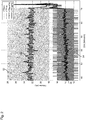
- the detection signals of the proximal flow sensor 44 are shown as “VTProx” with reference number 52 and of the distal flow sensor 48 as “VTServ” with reference number 54. These are time-discrete signals in their form recorded directly by the respective sensors 44 and 48.
- these signals can be used to carry out the fault detection according to the invention.
- these signals can be smooth these signals.
- a smoothing method is advantageous which only takes a few measurement signals into account and therefore does not suppress changes in the sensor signals that occur at short notice. Smoothing by forming a weighted moving average has proven to be advantageous for this, for example over the last 16 measured values.
- the measurement signals of the proximal flow sensor 44 and the distal flow sensor 48 are advantageously smoothed using the same measurement methods and the same filter coefficients. However, this does not have to be the case. Different smoothing methods or the same smoothing method with different filter coefficients can be used for the measurement signals from different sensors.
- the filter coefficients are the weighting factors of the respective measured values.
- the measured values in the middle of the last 16 measured values are weighted most heavily, with a linear increase from the most recent measured value to the mean measured value and a linear decrease from the mean measured value to the oldest measured value.
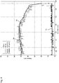
- the weighted smoothed mean VT SerfFilt is in Figure 2 with the reference number 56, and the weighted smoothed mean value VT ProxFilt with the reference number 58.
- the abscissa of the diagram of Figure 2 indicates the time in minutes, the ordinate the volume in milliliters.
- the change values that are important for detecting errors in the ventilation device according to the invention are used particularly advantageously as differences between the value of the current breath and the immediately preceding breath, the smoothed values preferably being used to form the differences.
- Reference numeral 64 denotes a threshold value which, when exceeded by the change value 62 of the proximal flow sensor 44, starts the control device 18 with the error detection method described in the introduction to the description.
- the start of the error detection method is coupled to the exceeding of the threshold value 64 in order not to use unnecessary computing power of the control device 18 for the error detection method.
- VT Serv reference VT Serv Filt k - 1
- VT Prox reference VT Prox Filt k - 1
- VT Serv total n VT Serv total n - 1 + VT Serv Diff n
- VT Prox total n VT Prox total n - 1 + VT Prox Diff n
- a total value is thus formed which, for the nth breath, is the total value of the immediately preceding (n-1) th breath plus the current change value of the nth breath.
- the control device 18 detects a jump error when the ratio of the sum value of the proximal flow sensor 44 to the reference value VT Prox reference of the proximal flow sensor 44 exceeds a predetermined reference threshold value, for example exceeds a reference threshold value of 0.08, which means that the sum of the change values of the proximal flow sensor since the start of the summation is at least 8% of the reference value.
- the reference threshold value can also have a value other than 8%, however, in previous tests, 8% has proven to be a very good reference threshold value.
- Another condition that can be added to the one mentioned in the previous paragraph is that the total value of the distal flow sensor 48 does not differ from the total value of the proximal flow sensor 44 by more than a further reference threshold value - this can be, for example, 10%.
- condition can be added that the current, preferably smoothed, value of the distal flow sensor 48 does not differ from its reference value by more than another reference threshold value.
- This still further reference threshold value can be between 1 and 5%, for example. tries have found a further reference threshold of 2% to be expedient.
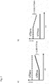
- FIG Figure 6 The case of a jump error occurring at the proximal flow sensor 44 is shown in FIG Figure 6 exemplarily shown thematically.
- control device 18 Only when all the conditions predetermined for reliable detection of a jump error are met does the control device 18 recognize the presence of a jump error and, for example, trigger a corresponding alarm.
- smoothed measured values are also used, with the smoothing of the measured values preferably taking place over a larger number of previous measured values than is the case with a jump error.
- the weighting coefficients b i are selected such that the sum of all weighting coefficients results in 1.
- the measured values can also be smoothed by a digital filter of higher order, preferably at least fourth order.
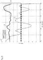
- the raw signals of the distal flow sensor 48 are provided with the reference number 66 and those of the proximal flow sensor 44 with the reference number 68.
- the smoothed signal of the distal flow sensor 48 is provided with the reference number 70, the smoothed signal of the proximal flow sensor 44 with the reference number 72.
- VT Serv Diff n VT Serv Filt n - VT Serv Filt n - 1
- VT Prox Diff n VT Prox Filt n - VT Prox Filt n - 1
- the change values of the measurement signals of the distal flow sensor 48 are shown in FIG Figure 5 denoted by reference number 74, that of the proximal flow sensor 44 with reference number 76.
- the error detection by the control device 18 begins only after predetermined start conditions have been met, for example when one of the change values is in Figure 5 tolerance band designated by 78 leaves around 0 ml and / or when the change values have different signs. In Figure 5 If the upper edge of the tolerance band is not shown, it ranges from -3 to +3 ml.
- the change value tolerance band the departure of which can be a start condition for the error detection by the control device 18, is preferably arranged symmetrically around the zero point. However, this does not have to be the case; depending on the application, there may also be limits that differ from one another in terms of amount.
- VT Serv total n VT Serv total n - 1 + VT Serv Diff n
- VT Prox total n VT Prox total n - 1 + VT Prox Diff n
- VT Serv reference VT Serv Filt k - 1
- VT Prox reference VT Prox Filt k - 1
- the control device 18 then recognizes the presence of a drift error in the flow sensor arrangement when the ratio of the change sum value VT Prox total [ n ] of the proximal flow sensor 44 to its reference value VT Prox reference exceeds a predetermined reference threshold and if at the same time the ratio of the change sum value VT Serv total [ n ] of the distal flow sensor 48 for its reference value VT ServBezug does not exceed a predetermined further reference threshold value.
- the reference threshold value of the proximal flow sensor 44 for the detection of a drift error can again be 8%, the further reference threshold value can be, for example, 2%.
- control device 18 also recognizes the presence of a drift error in the flow sensor arrangement when the ratio of the change sum value VT Serv total [ n ] of the distal flow sensor 48 to its reference value VT Serv reference exceeds the predetermined reference threshold and, at the same time, the ratio of the change sum value of the proximal flow sensor 44 VT Prox total [ n ] to its reference value VT Prox reference does not exceed the predetermined further reference threshold value.
- the exemplary values given in the previous paragraph for the reference threshold values apply.
- the conditions for detecting the drift error are preferably symmetrical with respect to the two reference threshold values.
- An additional condition for the detection of a drift error can be that one of the two change sum values exceeds a predetermined threshold amount of change, for example an amount of 2 ml.
- control device 18 preferably triggers an alarm, but preferably continues to operate the flow sensor arrangement.
Landscapes
- Health & Medical Sciences (AREA)
- Pulmonology (AREA)
- Heart & Thoracic Surgery (AREA)
- Engineering & Computer Science (AREA)
- Anesthesiology (AREA)
- Biomedical Technology (AREA)
- Emergency Medicine (AREA)
- Hematology (AREA)
- Life Sciences & Earth Sciences (AREA)
- Animal Behavior & Ethology (AREA)
- General Health & Medical Sciences (AREA)
- Public Health (AREA)
- Veterinary Medicine (AREA)
- Measurement Of The Respiration, Hearing Ability, Form, And Blood Characteristics Of Living Organisms (AREA)
- Measuring Volume Flow (AREA)
Applications Claiming Priority (2)
| Application Number | Priority Date | Filing Date | Title |
|---|---|---|---|
| DE102015216895.6A DE102015216895A1 (de) | 2015-09-03 | 2015-09-03 | Beatmungsvorrichtung mit Fehlererfassung für Durchflusssensoren |
| PCT/EP2016/070572 WO2017037152A1 (de) | 2015-09-03 | 2016-09-01 | Beatmungsvorrichtung mit fehlererfassung für durchflusssensoren |
Publications (2)
| Publication Number | Publication Date |
|---|---|
| EP3344317A1 EP3344317A1 (de) | 2018-07-11 |
| EP3344317B1 true EP3344317B1 (de) | 2020-10-28 |
Family
ID=56851612
Family Applications (1)
| Application Number | Title | Priority Date | Filing Date |
|---|---|---|---|
| EP16758203.0A Active EP3344317B1 (de) | 2015-09-03 | 2016-09-01 | Beatmungsvorrichtung mit fehlererfassung für durchflusssensoren |
Country Status (6)
| Country | Link |
|---|---|
| US (1) | US10905838B2 (enExample) |
| EP (1) | EP3344317B1 (enExample) |
| JP (1) | JP6840736B2 (enExample) |
| CN (1) | CN107949412B (enExample) |
| DE (1) | DE102015216895A1 (enExample) |
| WO (1) | WO2017037152A1 (enExample) |
Cited By (7)
| Publication number | Priority date | Publication date | Assignee | Title |
|---|---|---|---|---|
| DE102021116062A1 (de) | 2021-06-22 | 2022-12-22 | Hamilton Medical Ag | Beatmungsvorrichtung mit automatisierter Korrektur proximal gemessener Atemgasflusswerte während des Beatmungsbetriebs |
| US11709156B2 (en) | 2017-09-18 | 2023-07-25 | Waters Technologies Corporation | Use of vapor deposition coated flow paths for improved analytical analysis |
| US11709155B2 (en) | 2017-09-18 | 2023-07-25 | Waters Technologies Corporation | Use of vapor deposition coated flow paths for improved chromatography of metal interacting analytes |
| US11918936B2 (en) | 2020-01-17 | 2024-03-05 | Waters Technologies Corporation | Performance and dynamic range for oligonucleotide bioanalysis through reduction of non specific binding |
| US12180581B2 (en) | 2017-09-18 | 2024-12-31 | Waters Technologies Corporation | Use of vapor deposition coated flow paths for improved chromatography of metal interacting analytes |
| US12181452B2 (en) | 2017-09-18 | 2024-12-31 | Waters Technologies Corporation | Use of vapor deposition coated flow paths for improved chromatography of metal interacting analytes |
| US12352734B2 (en) | 2020-09-24 | 2025-07-08 | Waters Technologies Corporation | Chromatographic hardware improvements for separation of reactive molecules |
Families Citing this family (5)
| Publication number | Priority date | Publication date | Assignee | Title |
|---|---|---|---|---|
| US11027079B2 (en) * | 2016-06-22 | 2021-06-08 | Loewenstein Medical Technology S.A. | Ventilation device and method |
| DE102017217858A1 (de) * | 2017-10-06 | 2019-04-11 | Hamilton Medical Ag | Beatmungsvorrichtung mit automatisierter Erfassung eines Fehlers eines Durchflusssensors unter Berücksichtigung von Spontanatmung |
| DE102018121080A1 (de) | 2018-08-29 | 2020-03-05 | B. Braun Avitum Ag | Verfahren und Vorrichtung zur intermittierenden, pulsierenden Proportionierung einer Dialysierflüssigkeitsmischung |
| EP3649929A1 (en) * | 2018-11-06 | 2020-05-13 | Koninklijke Philips N.V. | An apparatus for use with a wearable cuff |
| CN116531628B (zh) * | 2023-06-13 | 2023-12-29 | 大庆油田总医院 | 一种智能麻醉呼吸安全监控系统及方法 |
Family Cites Families (25)
| Publication number | Priority date | Publication date | Assignee | Title |
|---|---|---|---|---|
| EP2305116A1 (en) * | 1993-11-05 | 2011-04-06 | ResMed Ltd. | Control of CPAP Treatment |
| SE503155C2 (sv) * | 1994-07-28 | 1996-04-01 | Comasec International Sa | Sätt och anordning för funktionskontroll vid andningsapparat |
| SE9504312L (sv) * | 1995-12-01 | 1996-12-23 | Siemens Elema Ab | Sätt vid styrning av en andningsapparat samt en andningsapparat |
| SE0000205D0 (sv) * | 2000-01-25 | 2000-01-25 | Siemens Elema Ab | Ventilator |
| DE10164313A1 (de) | 2001-12-28 | 2003-07-10 | Muefa Ag | Beatmungsvorrichtung |
| US20040149282A1 (en) * | 2002-12-02 | 2004-08-05 | Scott Laboratories, Inc. | Respiratory monitoring systems and methods |
| US7044129B1 (en) * | 2003-09-03 | 2006-05-16 | Ric Investments, Llc. | Pressure support system and method |
| US7115097B2 (en) * | 2003-10-09 | 2006-10-03 | Johnson Joseph L | Positive airway pressure notification system for treatment of breathing disorders during sleep |
| US20070062533A1 (en) * | 2005-09-21 | 2007-03-22 | Choncholas Gary J | Apparatus and method for identifying FRC and PEEP characteristics |
| US8474455B2 (en) * | 2006-01-10 | 2013-07-02 | Carefusion 207, Inc. | System and method for circuit compliance compensated volume assured pressure control in a patient respiratory ventilator |
| CN101528295A (zh) * | 2006-08-30 | 2009-09-09 | 雷斯梅德有限公司 | 确定cpap治疗过程中的泄漏 |
| ITMI20061755A1 (it) | 2006-09-14 | 2008-03-15 | Milano Politecnico | Apparato di supporto respiratorio e rilevamento non invasivo di dereclutamento alveolare per pazienti con insufficenze respiratorie |
| EP2111248B1 (en) | 2007-01-23 | 2016-04-20 | Fisher & Paykel Healthcare Limited | Humidification apparatus with rfid tag sensor |
| CN101288791B (zh) * | 2007-04-18 | 2011-09-28 | 深圳迈瑞生物医疗电子股份有限公司 | 一种麻醉机呼吸装置及其流量传感器的标定方法 |
| WO2009119449A1 (ja) | 2008-03-26 | 2009-10-01 | 国立大学法人 九州工業大学 | 気管チューブ維持管理システム |
| EP3597251B1 (en) * | 2008-06-05 | 2023-04-26 | ResMed Pty Ltd | Treatment of respiratory conditions |
| DE102009013396B3 (de) * | 2009-03-16 | 2010-08-05 | Dräger Medical AG & Co. KG | Vorrichtung und Verfahren zur Steuerung der Sauerstoffdosierung eines Beatmungsgerätes |
| JP5046057B2 (ja) * | 2009-08-06 | 2012-10-10 | 高圧ガス保安協会 | ガス遮断装置 |
| CH701755B1 (de) | 2009-09-07 | 2014-03-14 | Hamilton Medical Ag | Durchflussmessfühler. |
| EP2383008B1 (en) * | 2010-04-30 | 2013-11-06 | General Electric Company | Arrangement for maintaining volume of breathing gas in a desired level |
| US9259545B2 (en) * | 2011-11-05 | 2016-02-16 | Drägerwerk AG & Co. KGaA | Process for checking the function of a respiration system |
| DE102012010525A1 (de) * | 2011-07-02 | 2013-01-03 | Dräger Medical GmbH | Verfahren zur Funktionskontrolle eines Beatmungssystems |
| US9999742B2 (en) * | 2012-04-10 | 2018-06-19 | Fisher & Paykel Healthcare Limited | Combination CPAP and resuscitation systems and methods |
| EP3030302B1 (en) * | 2013-09-04 | 2023-02-22 | Fisher&Paykel Healthcare Limited | Improvements to flow therapy |
| US11491291B2 (en) * | 2015-03-31 | 2022-11-08 | Fisher & Paykel Healthcare Limited | Methods and apparatus for oxygenation and/or CO2 removal |
-
2015
- 2015-09-03 DE DE102015216895.6A patent/DE102015216895A1/de not_active Withdrawn
-
2016
- 2016-09-01 JP JP2018511656A patent/JP6840736B2/ja active Active
- 2016-09-01 EP EP16758203.0A patent/EP3344317B1/de active Active
- 2016-09-01 US US15/757,208 patent/US10905838B2/en active Active
- 2016-09-01 CN CN201680051327.9A patent/CN107949412B/zh active Active
- 2016-09-01 WO PCT/EP2016/070572 patent/WO2017037152A1/de not_active Ceased
Cited By (8)
| Publication number | Priority date | Publication date | Assignee | Title |
|---|---|---|---|---|
| US11709156B2 (en) | 2017-09-18 | 2023-07-25 | Waters Technologies Corporation | Use of vapor deposition coated flow paths for improved analytical analysis |
| US11709155B2 (en) | 2017-09-18 | 2023-07-25 | Waters Technologies Corporation | Use of vapor deposition coated flow paths for improved chromatography of metal interacting analytes |
| US12180581B2 (en) | 2017-09-18 | 2024-12-31 | Waters Technologies Corporation | Use of vapor deposition coated flow paths for improved chromatography of metal interacting analytes |
| US12181452B2 (en) | 2017-09-18 | 2024-12-31 | Waters Technologies Corporation | Use of vapor deposition coated flow paths for improved chromatography of metal interacting analytes |
| US12416607B2 (en) | 2017-09-18 | 2025-09-16 | Waters Technologies Corporation | Use of vapor deposition coated flow paths for improved chromatography of metal interacting analytes |
| US11918936B2 (en) | 2020-01-17 | 2024-03-05 | Waters Technologies Corporation | Performance and dynamic range for oligonucleotide bioanalysis through reduction of non specific binding |
| US12352734B2 (en) | 2020-09-24 | 2025-07-08 | Waters Technologies Corporation | Chromatographic hardware improvements for separation of reactive molecules |
| DE102021116062A1 (de) | 2021-06-22 | 2022-12-22 | Hamilton Medical Ag | Beatmungsvorrichtung mit automatisierter Korrektur proximal gemessener Atemgasflusswerte während des Beatmungsbetriebs |
Also Published As
| Publication number | Publication date |
|---|---|
| DE102015216895A1 (de) | 2017-03-09 |
| WO2017037152A1 (de) | 2017-03-09 |
| JP6840736B2 (ja) | 2021-03-10 |
| US10905838B2 (en) | 2021-02-02 |
| EP3344317A1 (de) | 2018-07-11 |
| US20190192796A1 (en) | 2019-06-27 |
| CN107949412B (zh) | 2020-12-18 |
| CN107949412A (zh) | 2018-04-20 |
| JP2018533999A (ja) | 2018-11-22 |
Similar Documents
| Publication | Publication Date | Title |
|---|---|---|
| EP3344317B1 (de) | Beatmungsvorrichtung mit fehlererfassung für durchflusssensoren | |
| EP3247437B1 (de) | Beatmungsgerät mit verbesserter synchronität beim übergang von exspiratorischem zu inspiratorischem betrieb | |
| EP1148907B1 (de) | Nichtinvasives verfahren zur optimierung der beatmung atelektatischer lungen | |
| EP3691723B1 (de) | Beatmungsvorrichtung mit automatisierter erfassung eines fehlers eines durchflusssensors unter berücksichtigung von spontanatmung | |
| DE102017217859A1 (de) | Beatmungsvorrichtung mit fluss- und drucksignalbasierter Erfassung von Fehlern eines Durchflusssensors der Vorrichtung | |
| EP1605999A1 (de) | Verfahren und vorrichtung zur erkennung von leckagen bei einrichtungen zum zuführen von atemgasen | |
| EP1960025A1 (de) | Schlauchsystem für beatmungsgeräte | |
| EP3156091B1 (de) | Vorrichtung zur überwachung einer diskonnektion | |
| WO2003055552A1 (de) | Beatmungsvorrichtung | |
| DE102010055253B4 (de) | Automatisch gesteuertes Beatmungsgerät | |
| DE102016013140A1 (de) | Beatmungsvorrichtung und Betriebsverfahren für eine Beatmungsvorrichtung mit einer Bestimmung von Hustenattacken | |
| DE102018003026A1 (de) | Beatmungsvorrichtung mit einem Sicherheitsventil | |
| EP3957347A1 (de) | Beatmungsgerät für high-flow-sauerstofftherapie | |
| EP3998941B1 (de) | Beatmungsvorrichtung zur ausführung eines verfahrens zur ermittlung einer funktionalen restkapazität einer patientenlunge | |
| EP4109466A1 (de) | Beatmungsvorrichtung mit automatisierter korrektur proximal gemessener atemgasflusswerte während des beatmungsbetriebs | |
| DE102020002656A1 (de) | Beatmungssteuereinheit und Beatmungssteuersystem | |
| DE102014119374B4 (de) | Beatmungssystem | |
| EP2153857A2 (de) | Verfahren und Vorrichtung zur Beatmung | |
| WO2011000359A1 (de) | Beatmungseinrichtung | |
| DE102025107151A1 (de) | Verfahren und Vorrichtung zur Messung der volumetrischen Kapnometrie, Oxymetrie und der funktionellen Residualkapazität (FRC) | |
| WO2007137825A2 (de) | Verfahren zur atemzugsweisen kontinuierlichen bestimmung der intratidalen dynamischen atemmechanik mittels gleitender multipler regressionsanalyse | |
| DE102025102271A1 (de) | Verfahren und Vorrichtung zum Lokalisieren eines Lecks | |
| WO2011009911A1 (de) | Atemmessvorrichtung und verfahren zu deren betrieb | |
| DE102021102886A1 (de) | Verfahren und Beatmungsvorrichtung zur Bestimmung eines Atemtraktinhalts an Atemgas während einer künstlichen Beatmung | |
| EP4251246A1 (de) | Erkennung von asynchronien bei der beatmung |
Legal Events
| Date | Code | Title | Description |
|---|---|---|---|
| STAA | Information on the status of an ep patent application or granted ep patent |
Free format text: STATUS: THE INTERNATIONAL PUBLICATION HAS BEEN MADE |
|
| PUAI | Public reference made under article 153(3) epc to a published international application that has entered the european phase |
Free format text: ORIGINAL CODE: 0009012 |
|
| STAA | Information on the status of an ep patent application or granted ep patent |
Free format text: STATUS: REQUEST FOR EXAMINATION WAS MADE |
|
| 17P | Request for examination filed |
Effective date: 20180328 |
|
| AK | Designated contracting states |
Kind code of ref document: A1 Designated state(s): AL AT BE BG CH CY CZ DE DK EE ES FI FR GB GR HR HU IE IS IT LI LT LU LV MC MK MT NL NO PL PT RO RS SE SI SK SM TR |
|
| AX | Request for extension of the european patent |
Extension state: BA ME |
|
| RIN1 | Information on inventor provided before grant (corrected) |
Inventor name: NOVOTNI, DOMINIK Inventor name: SCHRANZ, CHRISTOPH Inventor name: FRANKE, KAROLIN |
|
| DAV | Request for validation of the european patent (deleted) | ||
| DAX | Request for extension of the european patent (deleted) | ||
| REG | Reference to a national code |
Ref country code: DE Ref legal event code: R079 Ref document number: 502016011562 Country of ref document: DE Free format text: PREVIOUS MAIN CLASS: A61M0016000000 Ipc: A61M0016040000 |
|
| GRAP | Despatch of communication of intention to grant a patent |
Free format text: ORIGINAL CODE: EPIDOSNIGR1 |
|
| STAA | Information on the status of an ep patent application or granted ep patent |
Free format text: STATUS: GRANT OF PATENT IS INTENDED |
|
| INTG | Intention to grant announced |
Effective date: 20200421 |
|
| RIC1 | Information provided on ipc code assigned before grant |
Ipc: A61M 16/20 20060101ALI20200403BHEP Ipc: A61M 16/04 20060101AFI20200403BHEP Ipc: A61M 16/00 20060101ALI20200403BHEP Ipc: A61M 16/16 20060101ALI20200403BHEP |
|
| GRAS | Grant fee paid |
Free format text: ORIGINAL CODE: EPIDOSNIGR3 |
|
| GRAA | (expected) grant |
Free format text: ORIGINAL CODE: 0009210 |
|
| STAA | Information on the status of an ep patent application or granted ep patent |
Free format text: STATUS: THE PATENT HAS BEEN GRANTED |
|
| RIN1 | Information on inventor provided before grant (corrected) |
Inventor name: NOVOTNI, DOMINIK Inventor name: SCHRANZ, CHRISTOPH Inventor name: FRANKE, KAROLIN |
|
| AK | Designated contracting states |
Kind code of ref document: B1 Designated state(s): AL AT BE BG CH CY CZ DE DK EE ES FI FR GB GR HR HU IE IS IT LI LT LU LV MC MK MT NL NO PL PT RO RS SE SI SK SM TR |
|
| REG | Reference to a national code |
Ref country code: GB Ref legal event code: FG4D Free format text: NOT ENGLISH |
|
| REG | Reference to a national code |
Ref country code: CH Ref legal event code: EP |
|
| REG | Reference to a national code |
Ref country code: AT Ref legal event code: REF Ref document number: 1327586 Country of ref document: AT Kind code of ref document: T Effective date: 20201115 |
|
| REG | Reference to a national code |
Ref country code: DE Ref legal event code: R096 Ref document number: 502016011562 Country of ref document: DE |
|
| REG | Reference to a national code |
Ref country code: IE Ref legal event code: FG4D Free format text: LANGUAGE OF EP DOCUMENT: GERMAN |
|
| REG | Reference to a national code |
Ref country code: CH Ref legal event code: NV Representative=s name: E. BLUM AND CO. AG PATENT- UND MARKENANWAELTE , CH |
|
| REG | Reference to a national code |
Ref country code: NL Ref legal event code: MP Effective date: 20201028 |
|
| PG25 | Lapsed in a contracting state [announced via postgrant information from national office to epo] |
Ref country code: FI Free format text: LAPSE BECAUSE OF FAILURE TO SUBMIT A TRANSLATION OF THE DESCRIPTION OR TO PAY THE FEE WITHIN THE PRESCRIBED TIME-LIMIT Effective date: 20201028 Ref country code: GR Free format text: LAPSE BECAUSE OF FAILURE TO SUBMIT A TRANSLATION OF THE DESCRIPTION OR TO PAY THE FEE WITHIN THE PRESCRIBED TIME-LIMIT Effective date: 20210129 Ref country code: NO Free format text: LAPSE BECAUSE OF FAILURE TO SUBMIT A TRANSLATION OF THE DESCRIPTION OR TO PAY THE FEE WITHIN THE PRESCRIBED TIME-LIMIT Effective date: 20210128 Ref country code: RS Free format text: LAPSE BECAUSE OF FAILURE TO SUBMIT A TRANSLATION OF THE DESCRIPTION OR TO PAY THE FEE WITHIN THE PRESCRIBED TIME-LIMIT Effective date: 20201028 Ref country code: PT Free format text: LAPSE BECAUSE OF FAILURE TO SUBMIT A TRANSLATION OF THE DESCRIPTION OR TO PAY THE FEE WITHIN THE PRESCRIBED TIME-LIMIT Effective date: 20210301 |
|
| REG | Reference to a national code |
Ref country code: LT Ref legal event code: MG4D |
|
| PG25 | Lapsed in a contracting state [announced via postgrant information from national office to epo] |
Ref country code: ES Free format text: LAPSE BECAUSE OF FAILURE TO SUBMIT A TRANSLATION OF THE DESCRIPTION OR TO PAY THE FEE WITHIN THE PRESCRIBED TIME-LIMIT Effective date: 20201028 Ref country code: IS Free format text: LAPSE BECAUSE OF FAILURE TO SUBMIT A TRANSLATION OF THE DESCRIPTION OR TO PAY THE FEE WITHIN THE PRESCRIBED TIME-LIMIT Effective date: 20210228 Ref country code: LV Free format text: LAPSE BECAUSE OF FAILURE TO SUBMIT A TRANSLATION OF THE DESCRIPTION OR TO PAY THE FEE WITHIN THE PRESCRIBED TIME-LIMIT Effective date: 20201028 Ref country code: PL Free format text: LAPSE BECAUSE OF FAILURE TO SUBMIT A TRANSLATION OF THE DESCRIPTION OR TO PAY THE FEE WITHIN THE PRESCRIBED TIME-LIMIT Effective date: 20201028 Ref country code: BG Free format text: LAPSE BECAUSE OF FAILURE TO SUBMIT A TRANSLATION OF THE DESCRIPTION OR TO PAY THE FEE WITHIN THE PRESCRIBED TIME-LIMIT Effective date: 20210128 |
|
| PG25 | Lapsed in a contracting state [announced via postgrant information from national office to epo] |
Ref country code: NL Free format text: LAPSE BECAUSE OF FAILURE TO SUBMIT A TRANSLATION OF THE DESCRIPTION OR TO PAY THE FEE WITHIN THE PRESCRIBED TIME-LIMIT Effective date: 20201028 Ref country code: HR Free format text: LAPSE BECAUSE OF FAILURE TO SUBMIT A TRANSLATION OF THE DESCRIPTION OR TO PAY THE FEE WITHIN THE PRESCRIBED TIME-LIMIT Effective date: 20201028 |
|
| REG | Reference to a national code |
Ref country code: DE Ref legal event code: R097 Ref document number: 502016011562 Country of ref document: DE |
|
| PG25 | Lapsed in a contracting state [announced via postgrant information from national office to epo] |
Ref country code: EE Free format text: LAPSE BECAUSE OF FAILURE TO SUBMIT A TRANSLATION OF THE DESCRIPTION OR TO PAY THE FEE WITHIN THE PRESCRIBED TIME-LIMIT Effective date: 20201028 Ref country code: CZ Free format text: LAPSE BECAUSE OF FAILURE TO SUBMIT A TRANSLATION OF THE DESCRIPTION OR TO PAY THE FEE WITHIN THE PRESCRIBED TIME-LIMIT Effective date: 20201028 Ref country code: SM Free format text: LAPSE BECAUSE OF FAILURE TO SUBMIT A TRANSLATION OF THE DESCRIPTION OR TO PAY THE FEE WITHIN THE PRESCRIBED TIME-LIMIT Effective date: 20201028 Ref country code: LT Free format text: LAPSE BECAUSE OF FAILURE TO SUBMIT A TRANSLATION OF THE DESCRIPTION OR TO PAY THE FEE WITHIN THE PRESCRIBED TIME-LIMIT Effective date: 20201028 Ref country code: RO Free format text: LAPSE BECAUSE OF FAILURE TO SUBMIT A TRANSLATION OF THE DESCRIPTION OR TO PAY THE FEE WITHIN THE PRESCRIBED TIME-LIMIT Effective date: 20201028 Ref country code: SK Free format text: LAPSE BECAUSE OF FAILURE TO SUBMIT A TRANSLATION OF THE DESCRIPTION OR TO PAY THE FEE WITHIN THE PRESCRIBED TIME-LIMIT Effective date: 20201028 |
|
| PG25 | Lapsed in a contracting state [announced via postgrant information from national office to epo] |
Ref country code: DK Free format text: LAPSE BECAUSE OF FAILURE TO SUBMIT A TRANSLATION OF THE DESCRIPTION OR TO PAY THE FEE WITHIN THE PRESCRIBED TIME-LIMIT Effective date: 20201028 |
|
| PLBE | No opposition filed within time limit |
Free format text: ORIGINAL CODE: 0009261 |
|
| STAA | Information on the status of an ep patent application or granted ep patent |
Free format text: STATUS: NO OPPOSITION FILED WITHIN TIME LIMIT |
|
| 26N | No opposition filed |
Effective date: 20210729 |
|
| PG25 | Lapsed in a contracting state [announced via postgrant information from national office to epo] |
Ref country code: AL Free format text: LAPSE BECAUSE OF FAILURE TO SUBMIT A TRANSLATION OF THE DESCRIPTION OR TO PAY THE FEE WITHIN THE PRESCRIBED TIME-LIMIT Effective date: 20201028 |
|
| PG25 | Lapsed in a contracting state [announced via postgrant information from national office to epo] |
Ref country code: SI Free format text: LAPSE BECAUSE OF FAILURE TO SUBMIT A TRANSLATION OF THE DESCRIPTION OR TO PAY THE FEE WITHIN THE PRESCRIBED TIME-LIMIT Effective date: 20201028 |
|
| REG | Reference to a national code |
Ref country code: BE Ref legal event code: MM Effective date: 20210930 |
|
| PG25 | Lapsed in a contracting state [announced via postgrant information from national office to epo] |
Ref country code: IS Free format text: LAPSE BECAUSE OF FAILURE TO SUBMIT A TRANSLATION OF THE DESCRIPTION OR TO PAY THE FEE WITHIN THE PRESCRIBED TIME-LIMIT Effective date: 20210228 Ref country code: MC Free format text: LAPSE BECAUSE OF FAILURE TO SUBMIT A TRANSLATION OF THE DESCRIPTION OR TO PAY THE FEE WITHIN THE PRESCRIBED TIME-LIMIT Effective date: 20201028 |
|
| PG25 | Lapsed in a contracting state [announced via postgrant information from national office to epo] |
Ref country code: LU Free format text: LAPSE BECAUSE OF NON-PAYMENT OF DUE FEES Effective date: 20210901 Ref country code: IE Free format text: LAPSE BECAUSE OF NON-PAYMENT OF DUE FEES Effective date: 20210901 Ref country code: BE Free format text: LAPSE BECAUSE OF NON-PAYMENT OF DUE FEES Effective date: 20210930 |
|
| REG | Reference to a national code |
Ref country code: AT Ref legal event code: MM01 Ref document number: 1327586 Country of ref document: AT Kind code of ref document: T Effective date: 20210901 |
|
| PG25 | Lapsed in a contracting state [announced via postgrant information from national office to epo] |
Ref country code: AT Free format text: LAPSE BECAUSE OF NON-PAYMENT OF DUE FEES Effective date: 20210901 |
|
| PG25 | Lapsed in a contracting state [announced via postgrant information from national office to epo] |
Ref country code: HU Free format text: LAPSE BECAUSE OF FAILURE TO SUBMIT A TRANSLATION OF THE DESCRIPTION OR TO PAY THE FEE WITHIN THE PRESCRIBED TIME-LIMIT; INVALID AB INITIO Effective date: 20160901 |
|
| P01 | Opt-out of the competence of the unified patent court (upc) registered |
Effective date: 20230521 |
|
| PG25 | Lapsed in a contracting state [announced via postgrant information from national office to epo] |
Ref country code: CY Free format text: LAPSE BECAUSE OF FAILURE TO SUBMIT A TRANSLATION OF THE DESCRIPTION OR TO PAY THE FEE WITHIN THE PRESCRIBED TIME-LIMIT Effective date: 20201028 |
|
| PGFP | Annual fee paid to national office [announced via postgrant information from national office to epo] |
Ref country code: IT Payment date: 20230822 Year of fee payment: 8 |
|
| PG25 | Lapsed in a contracting state [announced via postgrant information from national office to epo] |
Ref country code: MK Free format text: LAPSE BECAUSE OF FAILURE TO SUBMIT A TRANSLATION OF THE DESCRIPTION OR TO PAY THE FEE WITHIN THE PRESCRIBED TIME-LIMIT Effective date: 20201028 |
|
| PG25 | Lapsed in a contracting state [announced via postgrant information from national office to epo] |
Ref country code: MT Free format text: LAPSE BECAUSE OF FAILURE TO SUBMIT A TRANSLATION OF THE DESCRIPTION OR TO PAY THE FEE WITHIN THE PRESCRIBED TIME-LIMIT Effective date: 20201028 |
|
| PGFP | Annual fee paid to national office [announced via postgrant information from national office to epo] |
Ref country code: CH Payment date: 20241001 Year of fee payment: 9 |
|
| PG25 | Lapsed in a contracting state [announced via postgrant information from national office to epo] |
Ref country code: IT Free format text: LAPSE BECAUSE OF NON-PAYMENT OF DUE FEES Effective date: 20240901 |
|
| REG | Reference to a national code |
Ref country code: CH Ref legal event code: U11 Free format text: ST27 STATUS EVENT CODE: U-0-0-U10-U11 (AS PROVIDED BY THE NATIONAL OFFICE) Effective date: 20251001 |
|
| PGFP | Annual fee paid to national office [announced via postgrant information from national office to epo] |
Ref country code: DE Payment date: 20250820 Year of fee payment: 10 |
|
| PGFP | Annual fee paid to national office [announced via postgrant information from national office to epo] |
Ref country code: GB Payment date: 20250820 Year of fee payment: 10 |
|
| PGFP | Annual fee paid to national office [announced via postgrant information from national office to epo] |
Ref country code: FR Payment date: 20250820 Year of fee payment: 10 |
|
| PGFP | Annual fee paid to national office [announced via postgrant information from national office to epo] |
Ref country code: SE Payment date: 20250820 Year of fee payment: 10 |