EP3344317B1 - Ventilator with error detection for flow sensors - Google Patents
Ventilator with error detection for flow sensors Download PDFInfo
- Publication number
- EP3344317B1 EP3344317B1 EP16758203.0A EP16758203A EP3344317B1 EP 3344317 B1 EP3344317 B1 EP 3344317B1 EP 16758203 A EP16758203 A EP 16758203A EP 3344317 B1 EP3344317 B1 EP 3344317B1
- Authority
- EP
- European Patent Office
- Prior art keywords
- flow sensor
- value
- measurement signal
- proximal
- distal
- Prior art date
- Legal status (The legal status is an assumption and is not a legal conclusion. Google has not performed a legal analysis and makes no representation as to the accuracy of the status listed.)
- Active
Links
- 238000001514 detection method Methods 0.000 title claims description 39
- 230000008859 change Effects 0.000 claims description 110
- 238000005259 measurement Methods 0.000 claims description 107
- 238000009423 ventilation Methods 0.000 claims description 84
- 230000029058 respiratory gaseous exchange Effects 0.000 claims description 36
- 238000001914 filtration Methods 0.000 claims description 6
- 230000003434 inspiratory effect Effects 0.000 claims description 6
- 238000000034 method Methods 0.000 claims description 6
- 230000008569 process Effects 0.000 claims description 3
- 238000012545 processing Methods 0.000 claims description 2
- 238000012935 Averaging Methods 0.000 claims 1
- 238000010998 test method Methods 0.000 description 16
- 238000009499 grossing Methods 0.000 description 10
- 210000004072 lung Anatomy 0.000 description 9
- 238000010586 diagram Methods 0.000 description 8
- 230000005540 biological transmission Effects 0.000 description 4
- 230000003750 conditioning effect Effects 0.000 description 4
- 238000011161 development Methods 0.000 description 4
- 230000000694 effects Effects 0.000 description 4
- 238000012360 testing method Methods 0.000 description 4
- 230000008901 benefit Effects 0.000 description 3
- 230000000241 respiratory effect Effects 0.000 description 3
- 239000003814 drug Substances 0.000 description 2
- 230000007257 malfunction Effects 0.000 description 2
- 230000002123 temporal effect Effects 0.000 description 2
- 239000000443 aerosol Substances 0.000 description 1
- 230000003444 anaesthetic effect Effects 0.000 description 1
- 229940035674 anesthetics Drugs 0.000 description 1
- 230000003110 anti-inflammatory effect Effects 0.000 description 1
- 230000015572 biosynthetic process Effects 0.000 description 1
- 230000001186 cumulative effect Effects 0.000 description 1
- 230000003247 decreasing effect Effects 0.000 description 1
- 230000006870 function Effects 0.000 description 1
- 239000003193 general anesthetic agent Substances 0.000 description 1
- 230000036541 health Effects 0.000 description 1
- 239000007788 liquid Substances 0.000 description 1
- 239000000463 material Substances 0.000 description 1
- 238000000691 measurement method Methods 0.000 description 1
- 230000008450 motivation Effects 0.000 description 1
- 238000011022 operating instruction Methods 0.000 description 1
- 230000008092 positive effect Effects 0.000 description 1
- 238000001556 precipitation Methods 0.000 description 1
- 230000001105 regulatory effect Effects 0.000 description 1
- 230000004044 response Effects 0.000 description 1
- 230000008054 signal transmission Effects 0.000 description 1
- 230000002269 spontaneous effect Effects 0.000 description 1
- 230000001960 triggered effect Effects 0.000 description 1
- 238000011144 upstream manufacturing Methods 0.000 description 1
- XLYOFNOQVPJJNP-UHFFFAOYSA-N water Substances O XLYOFNOQVPJJNP-UHFFFAOYSA-N 0.000 description 1
Images


Classifications
-
- A—HUMAN NECESSITIES
- A61—MEDICAL OR VETERINARY SCIENCE; HYGIENE
- A61M—DEVICES FOR INTRODUCING MEDIA INTO, OR ONTO, THE BODY; DEVICES FOR TRANSDUCING BODY MEDIA OR FOR TAKING MEDIA FROM THE BODY; DEVICES FOR PRODUCING OR ENDING SLEEP OR STUPOR
- A61M16/00—Devices for influencing the respiratory system of patients by gas treatment, e.g. mouth-to-mouth respiration; Tracheal tubes
- A61M16/0051—Devices for influencing the respiratory system of patients by gas treatment, e.g. mouth-to-mouth respiration; Tracheal tubes with alarm devices
-
- A—HUMAN NECESSITIES
- A61—MEDICAL OR VETERINARY SCIENCE; HYGIENE
- A61M—DEVICES FOR INTRODUCING MEDIA INTO, OR ONTO, THE BODY; DEVICES FOR TRANSDUCING BODY MEDIA OR FOR TAKING MEDIA FROM THE BODY; DEVICES FOR PRODUCING OR ENDING SLEEP OR STUPOR
- A61M16/00—Devices for influencing the respiratory system of patients by gas treatment, e.g. mouth-to-mouth respiration; Tracheal tubes
- A61M16/0057—Pumps therefor
- A61M16/0066—Blowers or centrifugal pumps
-
- A—HUMAN NECESSITIES
- A61—MEDICAL OR VETERINARY SCIENCE; HYGIENE
- A61M—DEVICES FOR INTRODUCING MEDIA INTO, OR ONTO, THE BODY; DEVICES FOR TRANSDUCING BODY MEDIA OR FOR TAKING MEDIA FROM THE BODY; DEVICES FOR PRODUCING OR ENDING SLEEP OR STUPOR
- A61M16/00—Devices for influencing the respiratory system of patients by gas treatment, e.g. mouth-to-mouth respiration; Tracheal tubes
- A61M16/021—Devices for influencing the respiratory system of patients by gas treatment, e.g. mouth-to-mouth respiration; Tracheal tubes operated by electrical means
- A61M16/022—Control means therefor
- A61M16/024—Control means therefor including calculation means, e.g. using a processor
-
- A—HUMAN NECESSITIES
- A61—MEDICAL OR VETERINARY SCIENCE; HYGIENE
- A61M—DEVICES FOR INTRODUCING MEDIA INTO, OR ONTO, THE BODY; DEVICES FOR TRANSDUCING BODY MEDIA OR FOR TAKING MEDIA FROM THE BODY; DEVICES FOR PRODUCING OR ENDING SLEEP OR STUPOR
- A61M16/00—Devices for influencing the respiratory system of patients by gas treatment, e.g. mouth-to-mouth respiration; Tracheal tubes
- A61M16/04—Tracheal tubes
- A61M16/0463—Tracheal tubes combined with suction tubes, catheters or the like; Outside connections
-
- A—HUMAN NECESSITIES
- A61—MEDICAL OR VETERINARY SCIENCE; HYGIENE
- A61M—DEVICES FOR INTRODUCING MEDIA INTO, OR ONTO, THE BODY; DEVICES FOR TRANSDUCING BODY MEDIA OR FOR TAKING MEDIA FROM THE BODY; DEVICES FOR PRODUCING OR ENDING SLEEP OR STUPOR
- A61M16/00—Devices for influencing the respiratory system of patients by gas treatment, e.g. mouth-to-mouth respiration; Tracheal tubes
- A61M16/08—Bellows; Connecting tubes ; Water traps; Patient circuits
- A61M16/0816—Joints or connectors
- A61M16/0841—Joints or connectors for sampling
- A61M16/0858—Pressure sampling ports
-
- A—HUMAN NECESSITIES
- A61—MEDICAL OR VETERINARY SCIENCE; HYGIENE
- A61M—DEVICES FOR INTRODUCING MEDIA INTO, OR ONTO, THE BODY; DEVICES FOR TRANSDUCING BODY MEDIA OR FOR TAKING MEDIA FROM THE BODY; DEVICES FOR PRODUCING OR ENDING SLEEP OR STUPOR
- A61M16/00—Devices for influencing the respiratory system of patients by gas treatment, e.g. mouth-to-mouth respiration; Tracheal tubes
- A61M16/10—Preparation of respiratory gases or vapours
- A61M16/14—Preparation of respiratory gases or vapours by mixing different fluids, one of them being in a liquid phase
-
- A—HUMAN NECESSITIES
- A61—MEDICAL OR VETERINARY SCIENCE; HYGIENE
- A61M—DEVICES FOR INTRODUCING MEDIA INTO, OR ONTO, THE BODY; DEVICES FOR TRANSDUCING BODY MEDIA OR FOR TAKING MEDIA FROM THE BODY; DEVICES FOR PRODUCING OR ENDING SLEEP OR STUPOR
- A61M16/00—Devices for influencing the respiratory system of patients by gas treatment, e.g. mouth-to-mouth respiration; Tracheal tubes
- A61M16/20—Valves specially adapted to medical respiratory devices
- A61M16/201—Controlled valves
- A61M16/202—Controlled valves electrically actuated
- A61M16/203—Proportional
- A61M16/204—Proportional used for inhalation control
-
- A—HUMAN NECESSITIES
- A61—MEDICAL OR VETERINARY SCIENCE; HYGIENE
- A61M—DEVICES FOR INTRODUCING MEDIA INTO, OR ONTO, THE BODY; DEVICES FOR TRANSDUCING BODY MEDIA OR FOR TAKING MEDIA FROM THE BODY; DEVICES FOR PRODUCING OR ENDING SLEEP OR STUPOR
- A61M16/00—Devices for influencing the respiratory system of patients by gas treatment, e.g. mouth-to-mouth respiration; Tracheal tubes
- A61M16/20—Valves specially adapted to medical respiratory devices
- A61M16/201—Controlled valves
- A61M16/202—Controlled valves electrically actuated
- A61M16/203—Proportional
- A61M16/205—Proportional used for exhalation control
-
- A—HUMAN NECESSITIES
- A61—MEDICAL OR VETERINARY SCIENCE; HYGIENE
- A61M—DEVICES FOR INTRODUCING MEDIA INTO, OR ONTO, THE BODY; DEVICES FOR TRANSDUCING BODY MEDIA OR FOR TAKING MEDIA FROM THE BODY; DEVICES FOR PRODUCING OR ENDING SLEEP OR STUPOR
- A61M16/00—Devices for influencing the respiratory system of patients by gas treatment, e.g. mouth-to-mouth respiration; Tracheal tubes
- A61M16/10—Preparation of respiratory gases or vapours
- A61M16/14—Preparation of respiratory gases or vapours by mixing different fluids, one of them being in a liquid phase
- A61M16/16—Devices to humidify the respiration air
- A61M16/162—Water-reservoir filling system, e.g. automatic
-
- A—HUMAN NECESSITIES
- A61—MEDICAL OR VETERINARY SCIENCE; HYGIENE
- A61M—DEVICES FOR INTRODUCING MEDIA INTO, OR ONTO, THE BODY; DEVICES FOR TRANSDUCING BODY MEDIA OR FOR TAKING MEDIA FROM THE BODY; DEVICES FOR PRODUCING OR ENDING SLEEP OR STUPOR
- A61M16/00—Devices for influencing the respiratory system of patients by gas treatment, e.g. mouth-to-mouth respiration; Tracheal tubes
- A61M16/0003—Accessories therefor, e.g. sensors, vibrators, negative pressure
- A61M2016/0027—Accessories therefor, e.g. sensors, vibrators, negative pressure pressure meter
-
- A—HUMAN NECESSITIES
- A61—MEDICAL OR VETERINARY SCIENCE; HYGIENE
- A61M—DEVICES FOR INTRODUCING MEDIA INTO, OR ONTO, THE BODY; DEVICES FOR TRANSDUCING BODY MEDIA OR FOR TAKING MEDIA FROM THE BODY; DEVICES FOR PRODUCING OR ENDING SLEEP OR STUPOR
- A61M16/00—Devices for influencing the respiratory system of patients by gas treatment, e.g. mouth-to-mouth respiration; Tracheal tubes
- A61M16/0003—Accessories therefor, e.g. sensors, vibrators, negative pressure
- A61M2016/003—Accessories therefor, e.g. sensors, vibrators, negative pressure with a flowmeter
- A61M2016/0033—Accessories therefor, e.g. sensors, vibrators, negative pressure with a flowmeter electrical
- A61M2016/0036—Accessories therefor, e.g. sensors, vibrators, negative pressure with a flowmeter electrical in the breathing tube and used in both inspiratory and expiratory phase
-
- A—HUMAN NECESSITIES
- A61—MEDICAL OR VETERINARY SCIENCE; HYGIENE
- A61M—DEVICES FOR INTRODUCING MEDIA INTO, OR ONTO, THE BODY; DEVICES FOR TRANSDUCING BODY MEDIA OR FOR TAKING MEDIA FROM THE BODY; DEVICES FOR PRODUCING OR ENDING SLEEP OR STUPOR
- A61M2205/00—General characteristics of the apparatus
- A61M2205/18—General characteristics of the apparatus with alarm
Definitions
- the present invention relates to a ventilation device for artificial ventilation according to the preamble of claim 1.
- a generic ventilation device is from the WO 03/055552 A1 known. This discloses the determination of leaks in an inspiration line by comparing the detection values of different sensors that detect the inspiratory flow.
- the WO 03/055552 A1 further teaches to check the plausibility of a sensor measured value by checking a gradient delivered by the same sensor or the sign of the measured value.
- Another ventilation device is known, for example, on the market as the "SERVO-U" product from Maquet.
- This known ventilation device uses an internal sensor inside a ventilation device as a distal flow sensor. The distal end of the ventilation line arrangement is connected to the ventilator.
- the known ventilation device uses a proximal flow sensor in the form of a hot-wire anemometer in a Y-connector, in which an inspiratory and an expiratory ventilation hose are combined in the direction of the patient to form a common ventilation line leading to the patient.
- the operating instructions for this known ventilation device indicate that the outputs from internal pressure and flow sensors are compared with the measurement result of the proximal sensor in the Y-connector and that the proximal sensor is deactivated if a significant discrepancy is found between the values used for comparison .
- a disadvantage of the known ventilation device and the error detection disclosed therein is that the mere error detection based on a comparison of measured values from two different sensors is only able to detect some of the errors actually occurring in a sensor arrangement.
- the ventilation line arrangement in the form of an elastic tube is located between the two sensors, which is stretched against its elasticity with each breath by the breathing gas flowing through it. Because of this hose elasticity, the two flow sensors arranged at different points in the breathing gas flow deliver different measured values at both detection points, even with the same effective breathing gas flow.
- the breathing gas that expands the tube passes the distal flow sensor, but not the proximal flow sensor, which is why the measured values of the distal flow sensor are generally higher than those of the proximal one.
- Ventilation devices are vital devices for patients who cannot breathe on their own or who cannot breathe sufficiently. Their correct function is therefore of crucial importance. The correct functioning of the ventilation devices in turn depends on the most precise possible recording of the amount of breathing gas supplied to a patient.
- the change value of the measurement signal of one flow sensor from the proximal and distal flow sensor can be compared with a measurement signal from the same flow sensor - that is, from the one flow sensor again - so that solely on the basis of signals from one and the same flow sensor: proximal or distal flow sensor, without taking the signals into account of the respective other flow sensor can be inferred to an error of one flow sensor, for example if its change value based on the last measurement signal before the change is unusually large or unusually small due to the prevailing operating conditions.
- change values from different sensors are compared with one another, these are simultaneous or quasi-simultaneous change values, that is to say change values that are determined at the same point in time or on the same breath.
- a change value of a measurement signal is compared with a measurement signal, this is a comparison of a change value with a measurement signal detected earlier, preferably with a measurement signal determined immediately before the change value.
- a particularly reliable error detection can be obtained if the above options for detecting errors in the flow sensor arrangement are used not only alternatively but also cumulatively.
- control device is designed to conclude that there is a fault in the flow sensor arrangement when the change value of the measurement signal of the one flow sensor from the distal and proximal flow sensor shows a change direction opposite to that Change value of the other flow sensor.
- jump error One error, which is referred to below as the "jump error" occurs suddenly and leads to a considerable error in the measurement result within a few seconds.
- drift error occurs gradually and develops over several minutes, up to half an hour or three quarters of an hour, into a considerable error in the measurement result.
- the proximal flow sensor is preferably a flow sensor that works according to the differential pressure principle, such as that from FIG DE 10 2010 040287 A1 is known
- the present invention should not be limited to ventilation devices with a flow sensor arrangement with at least one flow sensor operating on the differential pressure principle.
- the presently proposed improved ventilation device with increased accuracy in error detection in flow sensors can basically use any desired flow sensor, regardless of which physical operating principles it uses to measure the gas flow.
- the jump error in a proximal flow sensor operating on the differential pressure principle according to FIG DE 10 2010 040287 A1 occurs when a movable flap, which separates two pressure measuring chambers arranged one after the other in the flow direction, dips into the condensate collected in the sensor and thus has to overcome a greater resistance to its movement than in a dry sensor.
- Change values of the measurement signal of the proximal and distal flow sensors that occur one after the other are added up in order to quantify the overall change in the measurement signal of the respective flow sensor that occurs over the duration of the addition.
- This sum value of the change in the measurement signal can then be related to a reference variable in order to assess whether the flow sensor arrangement is working correctly or not. The assessment is made on the basis of a predetermined reference threshold value.
- change values of measurement signals occurring immediately one after the other are preferably summed up in order to be able to form the sum value over a period of time that is as short as possible and thus to be able to quickly determine a corresponding error in the flow sensor arrangement. It can also be ensured in this way that no change value of a measurement signal is left out of consideration for assessing the correctness of the operation of the flow sensor arrangement.
- the first and / or the second reference variable is a measurement signal value of the proximal flow sensor.
- the change values of the proximal flow sensor and the change values of the distal flow sensor can each be related to a sum of the changes in the proximal flow sensor as the more error-prone flow sensor from the proximal and distal flow sensors. This is often helpful for assessing the correct operation of the flow sensor arrangement, since the absolute value of a change in a measurement signal with regard to its plausibility can usually only be sensibly assessed in connection with the measurement value that is changed by the change.
- the accuracy of the error detection in particular a jump error
- the first and / or the second reference variable is a measurement signal value of the proximal flow sensor at or immediately before the start of the summation of the change values.
- the changes are then directly related to the measurement signal with which they are related to assess their plausibility or correctness.
- the ventilator does not need to continuously detect errors throughout its operation. It is sufficient to provide the computing power of the control device of the ventilation device for more precise error detection when this necessity emerges from the operation of the ventilation device.
- the control device of the ventilation device is therefore preferably designed to permanently monitor the operation of the flow sensor arrangement for errors in accordance with a first test method that requires less computing power, and is also designed to monitor the operation of the flow sensor arrangement when the first test method reveals a suspected error state of the flow sensor arrangement to monitor for errors according to a second test method requiring more computing power.
- the test as to whether the measurement signal value and / or the change value of the proximal flow sensor exceeds a predetermined signal threshold value is preferably carried out continuously and corresponds to the first test method referred to in the abstract above, which requires less computing power. Then, if the change value and / or the measurement signal value of the proximal flow sensor exceeds the predetermined signal threshold value, a suspected error state is determined, so that the above-described summation of change values and their comparison with reference values is preferably started.
- the first test method can be continued and it can be considered to end the second test method again if the first test method no longer indicates a suspected fault condition over a predetermined number of breathing cycles, for example if the measurement signal value and / or the change value of the proximal flow sensor exceeds a predetermined number of successively evaluated measurement signals no longer exceeds the predetermined signal threshold value.
- the distal flow sensor can be used to regulate the breathing gas flow as precisely as possible during a breath. This means that the breathing gas flow is changed during a breath on the basis of the measurement signal supplied by the distal flow sensor.
- the proximal flow sensor can be used to regulate the minute volume, as is used, for example, in the known ventilation modes ASV, Intellivent-ASV and APV.
- the minute volume is preferably set or regulated only by breath, ie. H. there is no change in the breathing gas flow during the breath based on the measurement signal from the proximal flow sensor.
- the distal flow sensor is preferably flowed through exclusively with inspiratory breathing gas, while the proximal flow sensor is flowed through with both inspiratory and expiratory breathing gas. This also results in an increased susceptibility of the proximal flow sensor to errors compared with that of the distal flow sensor.
- the control device is also designed to process the measurement signals of the proximal and distal flow sensors by breath . This has the advantage that most of the ventilation parameters which determine the operation of the ventilation device are available for each breath, that is, related to the respective breath to be performed.
- the first and / or the second reference variable is the measurement signal value of the proximal flow sensor is assigned to the breath immediately preceding the threshold breath. This, in turn, serves to establish a temporal relationship that is as immediate as possible between the measurement signals and / or change values to be used for fault detection of the flow sensor arrangement and the reference variable with which the signals or values are related.
- the summation is preferably carried out from a common start to the current breath stroke.
- any reference variables that appear suitable can be used for assessing the plausibility or correctness of change values of the measurement signal from one of the two or both flow sensors.
- a particularly meaningful reference variable for evaluating changes in the measurement signals or of the measurement signals themselves is a measurement signal value from the proximal flow sensor. Therefore, according to an advantageous development of the present invention, it can be provided that the third and / or the fifth reference variable is a measurement signal value of the proximal flow sensor.
- the third and / or the fifth reference variable is preferably a measurement signal value of the proximal flow sensor at or immediately before the start of the summation of the change values.
- the fourth and / or the sixth reference variable is a measurement signal value of the distal flow sensor, in particular a measurement signal value of the distal flow sensor at or immediately before the start of the summation of the change values.
- the summation of change values to form sum values begins when the amount of the change value of the measurement signal of the proximal and / or the distal flow sensor exceeds a predetermined threshold value.
- the comparison of the amount of the change value of the measurement signal of the proximal and / or the distal flow sensor with a predetermined amount threshold value is a first test method in the above sense that requires less computing power and is based on the above-described test method second test procedures requiring more computing power can be triggered.
- the duration of the execution of the test method for determining the drift error which requires more computing power
- a first test method for determining whether a second test method that requires more computing power should be started can alternatively or additionally be a comparison of the direction of change, i.e. for example the sign, of change values of the proximal and distal flow sensors based on the same breathing stroke. If the signs are different, i.e. if the measurement signals from the proximal and distal flow sensors change in different directions for the same breath, then there is sufficient suspicion of an error to start the second test method.
- control device can be designed to smooth the measuring signals of the flow sensors by filtering.
- a disruptive effect can be, for example, the spontaneous breathing activity of a patient ventilated with the ventilator.
- One possible type of effective filtering is the moving average. Since the jump error occurs quickly, ie within a few seconds, it is sufficient to form the moving average over a few change values and / or measured signal value, for example over no more than 25, preferably no more than 20, for example over 16 values.
- a sliding weighted average can preferably be formed in order, for example, to differently weight breaths taking place at different times. For example, when taking the moving average into account, it can make sense to take less into account the values immediately preceding the current measurement in time than values further back in time.
- the values to be filtered at the end of the time window to be considered for the filtering can also have a positive effect on the accuracy of the error determination again to be weighted less than values located approximately in the middle of the time window to be considered for the filtering.
- the measurement signal values of the two flow sensors can each be smoothed by a sliding mean value, in particular by a weighted sliding mean value.
- the measurement signal values to be smoothed can also be filtered by a digital filter with an order higher than 1, with filtering with an order higher than 2, particularly preferably with a fourth-order digital filter, achieving even better smoothing effects without loss of accuracy in error detection will.
- a digital filter is preferably used when determining the drift error.
- a larger number of measurement signals are preferably included in the smoothing of the measurement signals by an optionally weighted, moving average or by the digital filter than in the smoothing for determining the jump error.
- at least the last 50 measured values, particularly preferably at least the last 75 measured values, and most preferably at least the last 100 measured values are used for the smoothing to determine the drift error.
- the control device is then preferably designed to determine the change values on the basis of the smoothed measurement signals.
- An m-th order filter is the m-fold application of the filter structure referred to above with the filter output of the i-th order for the n-th breath as the input signal of the filter of the next higher (i + 1) -th order for the n-th Breath, where 1 ⁇ i ⁇ m applies.
- the proximal and distal flow sensors preferably do not work continuously, but rather time-discrete, so that the proximal and distal flow sensors each deliver one, preferably exactly one, measured value per breath, which represents the gas flow associated with this breath.
- control device In order not only to detect an error, but also to be able to derive measures from this in the event of an error detection, the control device is preferably designed to output an alarm when it concludes that an error is present. In contrast to the prior art, however, it is not necessary to switch off a sensor.
- the control device is therefore preferably designed to continue the processing of measurement signals from the proximal flow sensor and, in particular, to continue to check for the presence of a sensor error.
- FIG. 1 an embodiment of a ventilation device according to the invention is designated generally by 10.
- the ventilation device 10 is used for artificial ventilation of a human patient 12.
- the ventilation device 10 can be accommodated as a mobile ventilation device 10 on a rollable frame 13.
- the ventilation device 10 has a housing 14 in which - not visible from the outside because of the opaque housing material - a pressure change arrangement 16 and a control device 18 can be accommodated.
- the pressure change arrangement 16 is constructed in a manner known per se and can have a pump, a compressor, a blower, a pressure vessel, a reducing valve and the like.
- the ventilation device 10 also has an inspiration valve 20 and an expiration valve 22 in a manner known per se.
- the control device 18 is usually implemented as a computer or microprocessor. It includes an in Figure 1 Storage device, not shown, in order to be able to store data necessary for the operation of the ventilation device 10 and to be able to call it up if necessary. In network operation, the storage device can also be located outside the housing 14 and through a data transmission connection be connected to the control device 18. The data transmission connection can be formed by a cable or a radio link. However, in order to prevent disturbances in the data transmission connection from affecting the operation of the ventilation device 10, the memory device is preferably integrated into the control device 18 or at least received in the same housing 14 as this.
- the ventilation device 10 has a data input 24, which in the in Figure 1 shown example is represented by a keyboard.
- the control device 18 can receive data via various data inputs, for example via a network line, a radio link or via sensor connections 26, which will be discussed in detail below.
- the ventilation device 10 can have an output device 28, in the example shown a screen.
- the patient 12 is connected to the ventilation device 10, more precisely to the pressure change arrangement 16 in the housing 14, via a ventilation line arrangement 30.
- the patient 12 is intubated for this.
- the ventilation line arrangement 30 has an inspiration tube 32, via which fresh breathing gas can be conducted from the pressure change arrangement 16 into the lungs of the patient 12.
- the inspiration hose 32 can be interrupted and have a first inspiration sub-hose 34 and a second inspiration sub-hose 36, between which a conditioning device 38 for targeted humidification and, if necessary, temperature control of the fresh breathing gas supplied to the patient 12 can be provided.
- the conditioning device 38 can be connected to an external liquid supply 40, via which water for humidification or also a medicament, for example for anti-inflammatory purposes or to widen the airways, can be supplied to the breathing gas.
- volatile anesthetics can thus be delivered to the patient 12 in a controlled manner via the ventilation device 10.
- the conditioning device 38 ensures that the fresh breathing gas is supplied to the patient 12 with a predetermined moisture content, if necessary with the addition of a medicament aerosol and at a predetermined temperature.
- the ventilation line arrangement 30 has an expiration valve 22 and also an expiration tube 42, via which metabolized breathing gas is blown out of the patient's 12 lungs into the atmosphere.
- the inspiration tube 32 is coupled to the inspiration valve 20, the expiration tube 42 to the expiration valve 22. Only one of the two valves is open at the same time for the passage of a gas flow.
- the actuation control of the valves 20 and 22 is also carried out by the control device 18.
- the expiration valve 22 is initially closed and the inspiration valve 20 is opened for the duration of the inspiration phase, so that fresh breathing gas can be conducted from the housing 14 to the patient 12.
- a flow of the fresh breathing gas is brought about by a targeted pressure increase of the breathing gas by the pressure change arrangement 16. Due to the increase in pressure, the fresh breathing gas flows into the lungs of the patient 12 and there expands the area of the body close to the lungs, ie in particular the chest, against the individual elasticity of the parts of the body close to the lungs. This also increases the gas pressure inside the patient's 12 lungs.
- the inspiration valve 20 is closed and the expiration valve 22 is opened.
- the expiratory phase begins. Due to the increased gas pressure of the breathing gas in the lungs of the patient 12 until the end of the inspiration phase, the gas flows into the atmosphere after the expiration valve 22 is opened, with the gas pressure in the lungs of the patient 12 decreasing as the flow progresses. If the gas pressure in the lungs 12 reaches one positive end-expiratory pressure set on the ventilation device 10, that is to say a slightly higher pressure than atmospheric pressure, the expiration phase is ended with the closing of the expiration valve 22 and another ventilation cycle follows.
- the so-called ventilation tidal volume is supplied to the patient 12, that is to say the breathing gas volume per breath.
- the ventilation device 10, in particular the control device 18, is preferably designed to repeatedly update or determine ventilation operating parameters that characterize the ventilation operation of the ventilation device 10 during the ventilation operation in order to ensure that the ventilation operation is as optimal as possible at all times each patient 12 to be ventilated is coordinated.
- One or more ventilation operating parameters are particularly advantageously determined using the ventilation frequency, so that current ventilation operating parameters that are optimally adapted to the patient 12 can be provided for each ventilation cycle.
- the ventilation device 10 can be connected to one or more sensors for data transmission, which monitor the condition of the patient and / or the operation of the ventilation device.
- the flow sensor 44 can be coupled to the data inputs 26 of the control device 18 by means of a sensor line arrangement 46.
- the sensor line arrangement 46 can, but does not have to, comprise electrical signal transmission lines. It can also have hose lines which transmit the gas pressure prevailing in the flow direction on both sides of the flow sensor 44 to the data inputs 26, where these from in Figure 1 not shown Pressure sensors are quantified.
- the flow sensor 44 is shown here as a differential pressure flow sensor 44.
- the flow sensor 44 is preferably a flow sensor that works according to the differential pressure principle, but it can also be a flow sensor that works according to a different physical operating principle.
- a further flow sensor 48 is provided in the housing 14, which due to its greater distance from the patient 12 - compared to the proximal flow sensor 44 - is referred to as the distal flow sensor 48.
- the distal flow sensor 48 and its measurement signal can, for example, serve to regulate the breathing gas flow through the ventilation line arrangement 30, in the case of the distal flow sensor 48 more precisely through the inspiration tube 32, during an inspiration phase, while the proximal flow sensor 44 and its measurement signal regulate the amount supplied to the patient 12 Minute volume can serve.
- the distal flow sensor 48 thus preferably has a faster response behavior than the proximal flow sensor 44, since the measurement signal of the distal flow sensor 48 is also used to change the respiratory gas flow during a breath, while the measurement signal of the proximal flow sensor 44 is preferably only taken into account in a breath stroke, thus on its Basically, there is no change in the breathing gas flow through the Y connector 45 during a breath.
- the proximal flow sensor 44 is basically also able to detect the flow of expiratory breathing gas through the expiratory tube 42.
- the correct functioning of the flow sensors 44 and 48 is essential for the correct operation of the ventilation device 10 and thus for the health of the patient 12.
- proximal flow sensor 48 due to its proximity to the patient 12, is subject to a greater risk of error than the distal flow sensor 48.
- the proximal flow sensor 44, through which expiratory breathing gas also flows, is, for example, stronger than the distal flow sensor 48 the moisture contained in the breathing gas. This is all the more true when the distal flow sensor 48, as in the present example, of Figure 1 is arranged upstream of the conditioning device 38 in the direction of inspiration, and thus essentially only dry inspiratory breathing gas flows through it.
- the control device 18 of the ventilation device 10 is designed to monitor the operation of the flow sensor arrangement formed from the proximal flow sensor 44 and the distal flow sensor 48 in order to be able to detect a malfunction of the flow sensor arrangement in good time.
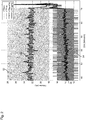
- the detection signals of the proximal flow sensor 44 are shown as “VTProx” with reference number 52 and of the distal flow sensor 48 as “VTServ” with reference number 54. These are time-discrete signals in their form recorded directly by the respective sensors 44 and 48.
- these signals can be used to carry out the fault detection according to the invention.
- these signals can be smooth these signals.
- a smoothing method is advantageous which only takes a few measurement signals into account and therefore does not suppress changes in the sensor signals that occur at short notice. Smoothing by forming a weighted moving average has proven to be advantageous for this, for example over the last 16 measured values.
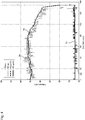
- the measurement signals of the proximal flow sensor 44 and the distal flow sensor 48 are advantageously smoothed using the same measurement methods and the same filter coefficients. However, this does not have to be the case. Different smoothing methods or the same smoothing method with different filter coefficients can be used for the measurement signals from different sensors.
- the filter coefficients are the weighting factors of the respective measured values.
- the measured values in the middle of the last 16 measured values are weighted most heavily, with a linear increase from the most recent measured value to the mean measured value and a linear decrease from the mean measured value to the oldest measured value.
- the weighted smoothed mean VT SerfFilt is in Figure 2 with the reference number 56, and the weighted smoothed mean value VT ProxFilt with the reference number 58.
- the abscissa of the diagram of Figure 2 indicates the time in minutes, the ordinate the volume in milliliters.
- the change values that are important for detecting errors in the ventilation device according to the invention are used particularly advantageously as differences between the value of the current breath and the immediately preceding breath, the smoothed values preferably being used to form the differences.
- Reference numeral 64 denotes a threshold value which, when exceeded by the change value 62 of the proximal flow sensor 44, starts the control device 18 with the error detection method described in the introduction to the description.
- the start of the error detection method is coupled to the exceeding of the threshold value 64 in order not to use unnecessary computing power of the control device 18 for the error detection method.
- VT Serv reference VT Serv Filt k - 1
- VT Prox reference VT Prox Filt k - 1
- VT Serv total n VT Serv total n - 1 + VT Serv Diff n
- VT Prox total n VT Prox total n - 1 + VT Prox Diff n
- a total value is thus formed which, for the nth breath, is the total value of the immediately preceding (n-1) th breath plus the current change value of the nth breath.
- the control device 18 detects a jump error when the ratio of the sum value of the proximal flow sensor 44 to the reference value VT Prox reference of the proximal flow sensor 44 exceeds a predetermined reference threshold value, for example exceeds a reference threshold value of 0.08, which means that the sum of the change values of the proximal flow sensor since the start of the summation is at least 8% of the reference value.
- the reference threshold value can also have a value other than 8%, however, in previous tests, 8% has proven to be a very good reference threshold value.
- Another condition that can be added to the one mentioned in the previous paragraph is that the total value of the distal flow sensor 48 does not differ from the total value of the proximal flow sensor 44 by more than a further reference threshold value - this can be, for example, 10%.
- condition can be added that the current, preferably smoothed, value of the distal flow sensor 48 does not differ from its reference value by more than another reference threshold value.
- This still further reference threshold value can be between 1 and 5%, for example. tries have found a further reference threshold of 2% to be expedient.
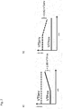
- FIG Figure 6 The case of a jump error occurring at the proximal flow sensor 44 is shown in FIG Figure 6 exemplarily shown thematically.
- control device 18 Only when all the conditions predetermined for reliable detection of a jump error are met does the control device 18 recognize the presence of a jump error and, for example, trigger a corresponding alarm.
- smoothed measured values are also used, with the smoothing of the measured values preferably taking place over a larger number of previous measured values than is the case with a jump error.
- the weighting coefficients b i are selected such that the sum of all weighting coefficients results in 1.
- the measured values can also be smoothed by a digital filter of higher order, preferably at least fourth order.
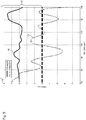
- the raw signals of the distal flow sensor 48 are provided with the reference number 66 and those of the proximal flow sensor 44 with the reference number 68.
- the smoothed signal of the distal flow sensor 48 is provided with the reference number 70, the smoothed signal of the proximal flow sensor 44 with the reference number 72.
- VT Serv Diff n VT Serv Filt n - VT Serv Filt n - 1
- VT Prox Diff n VT Prox Filt n - VT Prox Filt n - 1
- the change values of the measurement signals of the distal flow sensor 48 are shown in FIG Figure 5 denoted by reference number 74, that of the proximal flow sensor 44 with reference number 76.
- the error detection by the control device 18 begins only after predetermined start conditions have been met, for example when one of the change values is in Figure 5 tolerance band designated by 78 leaves around 0 ml and / or when the change values have different signs. In Figure 5 If the upper edge of the tolerance band is not shown, it ranges from -3 to +3 ml.
- the change value tolerance band the departure of which can be a start condition for the error detection by the control device 18, is preferably arranged symmetrically around the zero point. However, this does not have to be the case; depending on the application, there may also be limits that differ from one another in terms of amount.
- VT Serv total n VT Serv total n - 1 + VT Serv Diff n
- VT Prox total n VT Prox total n - 1 + VT Prox Diff n
- VT Serv reference VT Serv Filt k - 1
- VT Prox reference VT Prox Filt k - 1
- the control device 18 then recognizes the presence of a drift error in the flow sensor arrangement when the ratio of the change sum value VT Prox total [ n ] of the proximal flow sensor 44 to its reference value VT Prox reference exceeds a predetermined reference threshold and if at the same time the ratio of the change sum value VT Serv total [ n ] of the distal flow sensor 48 for its reference value VT ServBezug does not exceed a predetermined further reference threshold value.
- the reference threshold value of the proximal flow sensor 44 for the detection of a drift error can again be 8%, the further reference threshold value can be, for example, 2%.
- control device 18 also recognizes the presence of a drift error in the flow sensor arrangement when the ratio of the change sum value VT Serv total [ n ] of the distal flow sensor 48 to its reference value VT Serv reference exceeds the predetermined reference threshold and, at the same time, the ratio of the change sum value of the proximal flow sensor 44 VT Prox total [ n ] to its reference value VT Prox reference does not exceed the predetermined further reference threshold value.
- the exemplary values given in the previous paragraph for the reference threshold values apply.
- the conditions for detecting the drift error are preferably symmetrical with respect to the two reference threshold values.
- An additional condition for the detection of a drift error can be that one of the two change sum values exceeds a predetermined threshold amount of change, for example an amount of 2 ml.
- control device 18 preferably triggers an alarm, but preferably continues to operate the flow sensor arrangement.
Description
Die vorliegende Erfindung betrifft eine Beatmungsvorrichtung zur künstlichen Beatmung gemäß dem Oberbegriff des Anspruchs 1.The present invention relates to a ventilation device for artificial ventilation according to the preamble of
Eine gattungsgemäße Beatmungsvorrichtung ist aus der
Eine weitere Beatmungsvorrichtung ist beispielsweise im Markt als Produkt "SERVO-U" der Firma Maquet bekannt. Diese bekannte Beatmungsvorrichtung verwendet einen internen Sensor im Inneren eines Beatmungsgeräts als distalen Durchflusssensor. An dem Beatmungsgerät ist das distale Ende der Beatmungsleitungsanordnung angeschlossen. Weiter verwendet die bekannte Beatmungsvorrichtung einen proximalen Durchflusssensor in Form eines Heißdrahtanemometers in einem Y-Verbindungsstück, in welchem in Richtung zum Patienten hin ein inspiratorischer und ein expiratorischer Beatmungsschlauch zu einer gemeinsamen zum Patienten hin führenden Beatmungsleitung vereinigt werden. Die Bedienungsanleitung zu dieser bekannten Beatmungsvorrichtung gibt an, dass die Ausgaben von internen Druck- und Flusssensoren mit dem Messergebnis des proximalen Sensors in dem Y-Verbindungsstück verglichen werden und der proximale Sensor deaktiviert wird, wenn zwischen den zum Vergleich herangezogenen Werten eine signifikante Abweichung festgestellt wird.Another ventilation device is known, for example, on the market as the "SERVO-U" product from Maquet. This known ventilation device uses an internal sensor inside a ventilation device as a distal flow sensor. The distal end of the ventilation line arrangement is connected to the ventilator. Furthermore, the known ventilation device uses a proximal flow sensor in the form of a hot-wire anemometer in a Y-connector, in which an inspiratory and an expiratory ventilation hose are combined in the direction of the patient to form a common ventilation line leading to the patient. The operating instructions for this known ventilation device indicate that the outputs from internal pressure and flow sensors are compared with the measurement result of the proximal sensor in the Y-connector and that the proximal sensor is deactivated if a significant discrepancy is found between the values used for comparison .
Nachteilig an der bekannten Beatmungsvorrichtung und der dort offenbarten Fehlererfassung ist, dass die bloße Fehlererfassung aufgrund eines Vergleichs von Messwerten zweier unterschiedlicher Sensoren nur einen Teil der tatsächlich an einer Sensoranordnung auftretenden Fehler zu erfassen vermag. Außerdem liegt zwischen den beiden Sensoren die Beatmungsleitungsanordnung in Form eines elastischen Schlauches, der bei jedem Atemhub von dem ihn durchströmenden Atemgas gegen seine Elastizität gedehnt wird. Aufgrund dieser Schlauchelastizität liefern die beiden an unterschiedlichen Stellen im Atemgasstrom angeordneten Durchflusssensoren selbst bei gleichem effektiven Atemgasstrom an beiden Erfassungsstellen unterschiedliche Messwerte. Das den Schlauch dehnende Atemgas passiert nämlich den distalen Durchflusssensor, jedoch nicht den proximalen Durchflusssensor, weshalb die Messwerte des distalen Durchflusssensors in der Regel höher sind als jene des proximalen.A disadvantage of the known ventilation device and the error detection disclosed therein is that the mere error detection based on a comparison of measured values from two different sensors is only able to detect some of the errors actually occurring in a sensor arrangement. In addition, the ventilation line arrangement in the form of an elastic tube is located between the two sensors, which is stretched against its elasticity with each breath by the breathing gas flowing through it. Because of this hose elasticity, the two flow sensors arranged at different points in the breathing gas flow deliver different measured values at both detection points, even with the same effective breathing gas flow. The breathing gas that expands the tube passes the distal flow sensor, but not the proximal flow sensor, which is why the measured values of the distal flow sensor are generally higher than those of the proximal one.
Beatmungsvorrichtungen sind für Patienten, die selbstständig nicht oder nicht in ausreichendem Maße atmen können, lebenswichtige Geräte. Ihre korrekte Funktion ist daher von entscheidender Bedeutung. Die korrekte Funktion der Beatmungsvorrichtungen hängt wiederum von der möglichst präzisen Erfassung der einem Patienten zugeführten Atemgasmenge ab.Ventilation devices are vital devices for patients who cannot breathe on their own or who cannot breathe sufficiently. Their correct function is therefore of crucial importance. The correct functioning of the ventilation devices in turn depends on the most precise possible recording of the amount of breathing gas supplied to a patient.
Es ist daher Aufgabe der vorliegenden Erfindung, eine Beatmungsvorrichtung der eingangs genannten Art derart weiterzubilden, dass etwaige Fehlfunktionen der Durchflusssensoranordnung frühzeitig zuverlässig erkannt werden können.It is therefore the object of the present invention to develop a ventilation device of the type mentioned at the outset in such a way that any malfunctions of the flow sensor arrangement can be reliably detected at an early stage.
Diese Aufgabe wird erfindungsgemäß gelöst durch eine gattungsgemäße Beatmungsvorrichtung mit allen Merkmalen des Anspruchs 1. Durch die Verwendung von Änderungswerten des Messsignals anstelle des Messsignals selbst können Fehler der Durchflusssensoranordnung früher oder/und zuverlässiger als bis her erfasst werden. Somit ist es beispielsweise möglich, einen Fehler bereits zu erfassen, wenn sich die Messwerte des proximalen und des distalen Durchflusssensors zwar nur sehr geringfügig, jedoch in unterschiedliche Richtungen ändern, etwa der eine Durchflusssensor eine Erhöhung der Durchflussmenge anzeigt und der jeweils andere Durchflusssensor eine Verringerung. Somit kann bereits auf einen Fehler geschlossen werden, obwohl ein Vergleich der Messwerte der beiden Durchflusssensoren miteinander noch keine signifikante Abweichung voneinander aufzeigen würde.This object is achieved according to the invention by a generic ventilation device with all the features of
Alternativ oder zusätzlich kann der Änderungswert des Messsignals des einen Durchflusssensors aus proximalem und distalem Durchflusssensor mit einem Messsignal desselben Durchflusssensors - also wiederum des einen Durchflusssensors - verglichen werden, sodass allein aufgrund von Signalen ein und desselben Durchflusssensors: proximale oder distale Durchflusssensor, ohne Berücksichtigung der Signale des jeweils anderen Durchflusssensors auf einen Fehler des einen Durchflusssensors geschlossen werden kann, etwa wenn dessen Änderungswert bezogen auf das letzte Messsignal vor der Änderung aufgrund der vorherrschenden Betriebsbedingungen ungewöhnlich groß oder ungewöhnlich klein ist.Alternatively or additionally, the change value of the measurement signal of one flow sensor from the proximal and distal flow sensor can be compared with a measurement signal from the same flow sensor - that is, from the one flow sensor again - so that solely on the basis of signals from one and the same flow sensor: proximal or distal flow sensor, without taking the signals into account of the respective other flow sensor can be inferred to an error of one flow sensor, for example if its change value based on the last measurement signal before the change is unusually large or unusually small due to the prevailing operating conditions.
Wenn dabei Änderungswerte unterschiedlicher Sensoren miteinander verglichen werden, handelt es sich dabei um gleichzeitige oder quasi-gleichzeitige Änderungswerte, also um Änderungswerte die zum selben Zeitpunkt oder am selben Atemhub ermittelt werden.If change values from different sensors are compared with one another, these are simultaneous or quasi-simultaneous change values, that is to say change values that are determined at the same point in time or on the same breath.
Wird ein Änderungswert eines Messsignals mit einem Messsignal verglichen, handelt es sich dabei um einen Vergleich eines Änderungswerts mit einem zeitlich früher erfassten Messsignal, vorzugsweise mit einem zeitlich unmittelbar vor dem Änderungswert ermittelten Messsignal.If a change value of a measurement signal is compared with a measurement signal, this is a comparison of a change value with a measurement signal detected earlier, preferably with a measurement signal determined immediately before the change value.
Eine besonders sichere Fehlererkennung kann dabei erhalten werden, wenn die obigen Möglichkeiten zur Erkennung von Fehlern der Durchflusssensoranordnung nicht nur alternativ, sondern kumulativ angewendet werden.A particularly reliable error detection can be obtained if the above options for detecting errors in the flow sensor arrangement are used not only alternatively but also cumulatively.
Wie oben bereits angedeutet wurde, ist eine schnelle und effektive Fehlererkennung dann möglich, wenn die Steuereinrichtung dazu ausgebildet ist, dann auf einen Fehler der Durchflusssensoranordnung zu schließen, wenn der Änderungswert des Messsignals des einen Durchflusssensors aus distalem und proximalem Durchflusssensor eine entgegengesetzte Änderungsrichtung aufweist als der Änderungswert des jeweils anderen Durchflusssensors. Hierzu müssen nicht einmal Zahlenwerte miteinander verglichen werden, sondern es kann ein Vergleich von Vorzeichen der jeweiligen Änderungswerte miteinander ausreichen, um auf einen Fehler zu schließen.As already indicated above, rapid and effective error detection is possible if the control device is designed to conclude that there is a fault in the flow sensor arrangement when the change value of the measurement signal of the one flow sensor from the distal and proximal flow sensor shows a change direction opposite to that Change value of the other flow sensor. For this purpose, it is not even necessary to compare numerical values with one another, rather a comparison of the signs of the respective change values with one another can be sufficient to infer an error.
An der Durchflusssensoranordnung, insbesondere am proximalen Durchflusssensor, treten nach bisherigen Erfahrungen im Wesentlichen zwei unterschiedliche Fehlerarten auf, die sich hauptsächlich durch die Zeitdauer unterscheiden, in welcher sie sich entwickeln und auf die Beatmungsvorrichtung auswirken.According to previous experience, essentially two different types of errors occur on the flow sensor arrangement, in particular on the proximal flow sensor, which mainly differ in the length of time in which they develop and affect the ventilation device.
Der eine Fehler, der nachfolgend als "Sprungfehler" bezeichnet wird, tritt plötzlich auf und führt innerhalb weniger Sekunden zu einem beträchtlichen Fehler im Messergebnis.One error, which is referred to below as the "jump error", occurs suddenly and leads to a considerable error in the measurement result within a few seconds.
Der andere Fehler, der nachfolgend als "Driftfehler" bezeichnet wird, tritt schleichend auf und entwickelt sich über mehrere Minuten, bis hin zu einer halben Stunde oder einer Dreiviertelstunde, zu einem beträchtlichen Fehler im Messergebnis.The other error, referred to below as the "drift error", occurs gradually and develops over several minutes, up to half an hour or three quarters of an hour, into a considerable error in the measurement result.
Nach bisherigen Erkenntnissen stehen diese beiden Fehler höchstwahrscheinlich mit dem Niederschlag von Kondensat im proximalen Durchflusssensor im Zusammenhang. Dadurch, dass der proximale Durchflusssensor sehr nahe am Patienten vorgesehen ist, kann dieser stärker durch die Feuchtigkeit in der Atemluft beeinflusst werden. Während der Sprungfehler vor allem bei Durchflusssensoren, die nach dem Differenzdruckprinzip arbeiten, sehr gut verstanden wird, konnte für den Driftfehler bisher lediglich phänomenologisch festgestellt werden, dass dieser verschwindet, wenn man einen mit Kondensat beschlagenen Durchflusssensor durch einen trockenen ersetzt hat, nachdem man den Driftfehler erkannt hat.According to previous knowledge, these two errors are most likely related to the precipitation of condensate in the proximal flow sensor. Because the proximal flow sensor is provided very close to the patient, the patient can be more strongly influenced by the moisture in the breathing air. While the jump error is very well understood, especially with flow sensors that work according to the differential pressure principle, it was previously possible for the drift error It can only be ascertained phenomenologically that this disappears when one has replaced a condensate-fogged flow sensor with a dry one after recognizing the drift error.
Wenngleich wenigstens der proximale Durchflusssensor bevorzugt ein nach dem Differenzdruckprinzip arbeitender Durchflusssensor ist, wie er etwa aus der
Der Vollständigkeit halber sei erwähnt, dass nach derzeitiger Theorie der Sprungfehler in einem nach dem Differenzdruckprinzip arbeitenden proximalen Durchflusssensor gemäß der
Der Sprungfehler kann erfindungsgemäß dann schnell und sicher erkannt werden, wenn die Steuereinrichtung dazu ausgebildet ist, dann auf einen Fehler der Durchflusssensoranordnung zu schließen, wenn
- ein Verhältnis eines Summenwerts von nacheinander anfallenden Änderungswerten des Messsignals des proximalen Durchflusssensors zu einer ersten Bezugsgröße einen vorbestimmten Bezugsschwellenwert übersteigt und
- wenn ein Verhältnis eines Summenwerts von nacheinander anfallenden Änderungswerten des Messsignals des distalen Durchflusssensors zu einer zweiten Bezugsgröße einen vorbestimmten Bezugsschwellenwert unterschreitet.
- a ratio of a sum value of successively occurring change values of the measurement signal of the proximal flow sensor to a first reference variable exceeds a predetermined reference threshold value and
- when a ratio of a sum value of successively occurring change values of the measurement signal of the distal flow sensor to a second reference value falls below a predetermined reference threshold value.
Dabei werden also nacheinander anfallende Änderungswerte des Messsignals des proximalen und des distalen Durchflusssensors aufsummiert, um die über die Dauer der Summierung insgesamt auftretende Änderung des Messsignals des jeweiligen Durchflusssensors zu quantifizieren. Dieser Summenwert der Änderung des Messsignals kann dann mit einer Bezugsgröße in Bezug gesetzt werden, um zu beurteilen, ob die Durchflusssensoranordnung korrekt arbeitet oder nicht. Die Beurteilung erfolgt anhand eines vorbestimmten Bezugsschwellenwertes.Change values of the measurement signal of the proximal and distal flow sensors that occur one after the other are added up in order to quantify the overall change in the measurement signal of the respective flow sensor that occurs over the duration of the addition. This sum value of the change in the measurement signal can then be related to a reference variable in order to assess whether the flow sensor arrangement is working correctly or not. The assessment is made on the basis of a predetermined reference threshold value.
Bevorzugt werden zur Bildung des Summenwerts unmittelbar nacheinander anfallende Änderungswerte von Messsignalen aufsummiert, um den Summenwert über einen möglichst kurzen Zeitraum bilden zu können und so schnell einen entsprechenden Fehler in der Durchflusssensoranordnung ermitteln zu können. Außerdem kann so sichergestellt werden, dass kein Änderungswert eines Messsignals für die Beurteilung der Korrektheit des Betriebs der Durchflusssensoranordnung außer Betracht bleibt.To form the sum value, change values of measurement signals occurring immediately one after the other are preferably summed up in order to be able to form the sum value over a period of time that is as short as possible and thus to be able to quickly determine a corresponding error in the flow sensor arrangement. It can also be ensured in this way that no change value of a measurement signal is left out of consideration for assessing the correctness of the operation of the flow sensor arrangement.
Gemäß einer bevorzugten Weiterbildung der vorliegenden Erfindung ist die erste oder/und die zweite Bezugsgröße ein Messsignalwert des proximalen Durchflusssensors. Dadurch können die Änderungswerte des proximalen Durchflusssensors und die Änderungswerte des distalen Durchflusssensors jeweils mit einer Summe der Änderungen des proximalen Durchflusssensors als dem fehleranfälligeren Durchflusssensor aus proximalem und distalem Durchflusssensor in Bezug gesetzt werden. Dies ist für die Beurteilung des korrekten Betriebs der Durchflusssensoranordnung häufig hilfreich, da der absolute Wert einer Änderung eines Messsignals hinsichtlich seiner Plausibilität in der Regel nur im Zusammenhang mit dem Messwert, der durch die Änderung geändert wird, sinnvoll beurteilbar ist. Dementsprechend kann die Genauigkeit der Fehlererfassung, insbesondere eines Sprungfehlers, dadurch erhöht werden, dass die erste oder/und die zweite Bezugsgröße ein Messsignalwert des proximalen Durchflusssensors bei oder unmittelbar vor dem Beginn der Aufsummierung der Änderungswerte ist. Dann stehen die Änderungen in unmittelbarem Bezug zu dem Messsignal, mit dem sie zur Beurteilung ihrer Plausibilität bzw. Richtigkeit in Beziehung gesetzt werden.According to a preferred development of the present invention, the first and / or the second reference variable is a measurement signal value of the proximal flow sensor. As a result, the change values of the proximal flow sensor and the change values of the distal flow sensor can each be related to a sum of the changes in the proximal flow sensor as the more error-prone flow sensor from the proximal and distal flow sensors. This is often helpful for assessing the correct operation of the flow sensor arrangement, since the absolute value of a change in a measurement signal with regard to its plausibility can usually only be sensibly assessed in connection with the measurement value that is changed by the change. Accordingly, the accuracy of the error detection, in particular a jump error, can be increased in that the first and / or the second reference variable is a measurement signal value of the proximal flow sensor at or immediately before the start of the summation of the change values. The changes are then directly related to the measurement signal with which they are related to assess their plausibility or correctness.
Die Beatmungsvorrichtung muss jedoch nicht dauerhaft eine Fehlererfassung während ihres gesamten Betriebs durchführen. Es genügt, Rechenleistung der Steuereinrichtung der Beatmungsvorrichtung dann für eine genauere Fehlererfassung bereitzustellen, wenn sich diese Notwendigkeit aus dem Betrieb der Beatmungsvorrichtung heraus abzeichnet.However, the ventilator does not need to continuously detect errors throughout its operation. It is sufficient to provide the computing power of the control device of the ventilation device for more precise error detection when this necessity emerges from the operation of the ventilation device.
Bevorzugt ist daher die Steuereinrichtung der Beatmungsvorrichtung dazu ausgebildet, den Betrieb der Durchflusssensoranordnung dauerhaft gemäß einem ersten, weniger Rechenleistung erfordernden Prüfverfahren auf Fehler zu überwachen, und ist weiter dazu ausgebildet, dann, wenn das erste Prüfverfahren einen Fehlerverdachtszustand der Durchflusssensoranordnung aufzeigt, den Betrieb der Durchflusssensoranordnung gemäß einem zweiten, mehr Rechenleistung erfordernden Prüfverfahren auf Fehler zu überwachen.The control device of the ventilation device is therefore preferably designed to permanently monitor the operation of the flow sensor arrangement for errors in accordance with a first test method that requires less computing power, and is also designed to monitor the operation of the flow sensor arrangement when the first test method reveals a suspected error state of the flow sensor arrangement to monitor for errors according to a second test method requiring more computing power.
Für den oben bereits beschriebenen bevorzugten Fall eines intensiven Prüfverfahrens kann dies bedeuten, dass die Steuereinrichtung dazu ausgebildet ist, mit der Aufsummierung von Änderungswerten zu beginnen, wenn der Messsignalwert oder/und der Änderungswert des proximalen Durchflusssensors einen vorbestimmten Signalschwellenwert übersteigt. Die Prüfung, ob der Messsignalwert oder/und der Änderungswert des proximalen Durchflusssensors einen vorbestimmten Signalschwellenwert übersteigt, wird bevorzugt dauerhaft ausgeführt und entspricht dem oben abstrakt bezeichneten ersten Prüfverfahren, welches weniger Rechenleistung erfordert. Dann, wenn der Änderungswert oder/und der Messsignalwert des proximalen Durchflusssensors den vorbestimmten Signalschwellenwert übersteigt, ist ein Fehlerverdachtszustand ermittelt, sodass bevorzugt mit der oben beschriebenen Aufsummierung von Änderungswerten und deren Vergleich mit Bezugswerten begonnen wird.For the preferred case of an intensive test method already described above, this can mean that the control device is designed to start adding up change values when the measurement signal value and / or the change value of the proximal flow sensor exceeds a predetermined signal threshold value. The test as to whether the measurement signal value and / or the change value of the proximal flow sensor exceeds a predetermined signal threshold value is preferably carried out continuously and corresponds to the first test method referred to in the abstract above, which requires less computing power. Then, if the change value and / or the measurement signal value of the proximal flow sensor exceeds the predetermined signal threshold value, a suspected error state is determined, so that the above-described summation of change values and their comparison with reference values is preferably started.
Parallel kann das erste Prüfverfahren weitergeführt werden und es kann daran gedacht sein, das zweite Prüfverfahren wieder zu beenden, wenn das erste Prüfverfahren über eine vorbestimmte Anzahl von Atemzyklen keinen Fehlerverdachtszustand mehr aufzeigt, also beispielsweise wenn der Messsignalwert oder/und der Änderungswert des proximalen Durchflusssensors über eine vorbestimmte Anzahl nacheinander ausgewerteter Messsignale den vorbestimmten Signalschwellenwert nicht mehr übersteigt.At the same time, the first test method can be continued and it can be considered to end the second test method again if the first test method no longer indicates a suspected fault condition over a predetermined number of breathing cycles, for example if the measurement signal value and / or the change value of the proximal flow sensor exceeds a predetermined number of successively evaluated measurement signals no longer exceeds the predetermined signal threshold value.
Es kann jedoch ebenso daran gedacht sein, das zweite, mehr Rechenleistung erfordernde Prüfverfahren bis zum Ende des Betriebs der Beatmungsvorrichtung fortzusetzen, wenn einmal ein Fehlerverdachtszustand ermittelt wurde.However, it can also be considered to continue the second test method, which requires more computing power, until the end of operation of the ventilation device, once a suspected fault condition has been determined.
In einer bevorzugten Ausgestaltung der Beatmungsvorrichtung kann der distale Durchflusssensor zur möglichst genauen Regelung des Atemgasflusses während eines Atemhubs dienen. Dies bedeutet, dass der Atemgasfluss während eines Atemhubs auf Grundlage des vom distalen Durchflusssensor gelieferten Messsignals verändert wird.In a preferred embodiment of the ventilation device, the distal flow sensor can be used to regulate the breathing gas flow as precisely as possible during a breath. This means that the breathing gas flow is changed during a breath on the basis of the measurement signal supplied by the distal flow sensor.
Demgegenüber kann der proximale Durchflusssensor zur Regelung des Minutenvolumens herangezogen werden, wie es etwa bei den bekannten Beatmungsmodi ASV, Intellivent-ASV und APV verwendet wird. Hierbei wird bevorzugt das Minutenvolumen nur atemhubsweise eingestellt bzw. geregelt, d. h. es erfolgt keine Veränderung des Atemgasflusses während des Atemhubs auf Grundlage des Messsignals des proximalen Durchflusssensors. Dies hat den Vorteil, dass das dem Patienten tatsächlich verabreichte Atemgasvolumen mit dem näher beim Patienten angeordneten proximalen Durchflusssensor genauer als mit dem distalen Durchflusssensor bestimmt werden kann, unter anderem auch weil die Genauigkeit des Messsignals negativ beeinflussende Effekte, wie etwa die Elastizität von Schlauchleitungen im Beatmungsschlauch, sich auf das Messsignal des proximalen Durchflusssensors nicht oder nur in sehr geringem Umfang auswirken.In contrast, the proximal flow sensor can be used to regulate the minute volume, as is used, for example, in the known ventilation modes ASV, Intellivent-ASV and APV. In this case, the minute volume is preferably set or regulated only by breath, ie. H. there is no change in the breathing gas flow during the breath based on the measurement signal from the proximal flow sensor. This has the advantage that the respiratory gas volume actually administered to the patient can be determined more precisely with the proximal flow sensor located closer to the patient than with the distal flow sensor, among other things because the accuracy of the measurement signal is negatively influenced by effects such as the elasticity of tubing in the ventilation tube , do not affect the measurement signal of the proximal flow sensor or only to a very small extent.
Aufgrund der Anordnung des distalen und des proximalen Durchflusssensors wird der distale Durchflusssensor bevorzugt ausschließlich mit inspiratorischem Atemgas durchströmt, während der proximale Durchflusssensor sowohl mit inspiratorischem als auch mit exspiratorischem Atemgas durchströmt wird. Auch hieraus ergibt sich eine verglichen mit jener des distalen Durchflusssensors erhöhte Fehleranfälligkeit des proximalen Durchflusssensors.Due to the arrangement of the distal and proximal flow sensors, the distal flow sensor is preferably flowed through exclusively with inspiratory breathing gas, while the proximal flow sensor is flowed through with both inspiratory and expiratory breathing gas. This also results in an increased susceptibility of the proximal flow sensor to errors compared with that of the distal flow sensor.
Da die Beatmungsvorrichtung, wenngleich sie wie oben beschrieben Atemgasflüsse auch während eines Atemhubs verändert, im Wesentlichen den Patienten mit diskreten Atemhüben beatmet, kann bevorzugt daran gedacht sein, dass auch die Steuereinrichtung dazu ausgebildet ist, die Messsignale des proximalen und des distalen Durchflusssensors atemhubsweise zu verarbeiten. Dies hat den Vorteil, dass die meisten Beatmungsparameter, welche den Betrieb der Beatmungsvorrichtung bestimmen, atemhubsweise, also auf den jeweiligen auszuführenden Atemhubs bezogen, vorliegen.Since the ventilation device, although it also changes respiratory gas flows during a breath as described above, essentially ventilates the patient with discrete breaths, it can preferably be considered that the control device is also designed to process the measurement signals of the proximal and distal flow sensors by breath . This has the advantage that most of the ventilation parameters which determine the operation of the ventilation device are available for each breath, that is, related to the respective breath to be performed.
In diesem Fall kann gemäß einer bevorzugten Weiterbildung zur weiteren Erhöhung der Genauigkeit der Fehlererkennung daran gedacht sein, dann, wenn der Messsignalwert des proximalen Durchflusssensors den vorbestimmten Signalschwellenwert bei einem Schwellen-Atemhub übersteigt, die erste oder/und die zweite Bezugsgröße der Messsignalwert des proximalen Durchflusssensors ist, welcher dem dem Schwellen-Atemhub unmittelbar vorhergehenden Atemhub zugeordnet ist. Auch dies dient wiederum der Herstellung eines möglichst unmittelbaren zeitlichen Zusammenhangs zwischen den für die Fehlererkennung der Durchflusssensoranordnung heranzuziehenden Messsignalen oder/und Änderungswerten und der Bezugsgröße, mit der die Signale bzw. Werte in Beziehung gesetzt werden.In this case, according to a preferred development, to further increase the accuracy of the error detection, when the measurement signal value of the proximal flow sensor exceeds the predetermined signal threshold value during a threshold breathing stroke, the first and / or the second reference variable is the measurement signal value of the proximal flow sensor is assigned to the breath immediately preceding the threshold breath. This, in turn, serves to establish a temporal relationship that is as immediate as possible between the measurement signals and / or change values to be used for fault detection of the flow sensor arrangement and the reference variable with which the signals or values are related.
Versuche haben gezeigt, dass der Driftfehler dadurch gut erfasst werden kann, dass die Steuereinrichtung dazu ausgebildet ist, dann auf einen Fehler der Durchflusssensoranordnung zu schließen, wenn
- ein Verhältnis eines Summenwerts von nacheinander anfallenden, vorzugsweise unmittelbar aufeinanderfolgenden, Änderungswerten des Messsignals des proximalen Durchflusssensors zu einer dritten Bezugsgröße einen vorbestimmten Bezugsschwellenwert übersteigt und
- wenn ein Verhältnis eines Summenwerts von nacheinander anfallenden, vorzugsweise unmittelbar aufeinanderfolgenden, Änderungswerten des Messsignals des distalen Durchflusssensors zu einer vierten Bezugsgröße einen vorbestimmten Bezugsschwellenwert unterschreitet,
- ein Verhältnis eines Summenwerts von nacheinander anfallenden, vorzugsweise unmittelbar aufeinanderfolgenden, Änderungswerten des Messsignals des proximalen Durchflusssensors zu einer fünften Bezugsgröße einen vorbestimmten Bezugsschwellenwert unterschreitet und
- wenn ein Verhältnis eines Summenwerts von nacheinander anfallenden, vorzugsweise unmittelbar aufeinanderfolgenden, Änderungswerten des Messsignals des distalen Durchflusssensors zu einer sechsten Bezugsgröße einen vorbestimmten Bezugsschwellenwert übersteigt.
- a ratio of a sum value of successively occurring, preferably immediately consecutive, change values of the measurement signal of the proximal flow sensor to a third reference value exceeds a predetermined reference threshold value and
- if a ratio of a sum value of successively occurring, preferably immediately consecutive, change values of the measurement signal of the distal flow sensor to a fourth reference value falls below a predetermined reference threshold value,
- a ratio of a sum value of successively occurring, preferably immediately consecutive, change values of the measurement signal of the proximal flow sensor to a fifth reference value falls below a predetermined reference threshold value and
- when a ratio of a sum value of successively occurring, preferably immediately successive, change values of the measurement signal of the distal flow sensor to a sixth reference value exceeds a predetermined reference threshold value.
Es sei an dieser Stelle klargestellt, dass die Verwendung von Ordinalzahlen zur Unterscheidung der Bezugsschwellenwerte in der vorliegenden Anmeldung die Reihenfolge der Nennung der Bezugsschwellenwerte im Anmeldungstext wiedergibt und nicht als Angabe einer Mindestanzahl an Bezugsschwellenwerten in der Beatmungsvorrichtung verstanden werden soll.It should be made clear at this point that the use of ordinal numbers to differentiate the reference threshold values in the present application reflects the order in which the reference threshold values are named in the application text and should not be understood as indicating a minimum number of reference threshold values in the ventilator.
Zu den Vorteilen der Verwendung unmittelbar aufeinanderfolgender Änderungswerte sei auf die obigen Ausführungen zur Erfassung des Sprungfehlers verwiesen, die auch hier gelten. Die genannten Bezugsschwellenwerte lassen sich durch Versuche unter Berücksichtigung medizinischer Randbedingungen ohne nennenswerten Aufwand ermitteln.Regarding the advantages of using directly successive change values, reference is made to the above explanations on the detection of the jump error, which also apply here. The reference threshold values mentioned can be determined without any significant effort by means of tests taking into account medical boundary conditions.
Grundsätzlich kann der Driftfehler mit den vorstehend genannten Bedingungen bereits zuverlässig ermittelt werden. Eine noch höhere Genauigkeit der Erfassung des Driftfehlers kann dadurch erreicht werden, dass die Steuereinrichtung dazu ausgebildet ist, nur dann auf einen Fehler der Durchflusssensoranordnung zu schließen, wenn zusätzlich
- der Summenwert von nacheinander anfallenden, vorzugsweise unmittelbar aufeinanderfolgenden, Änderungswerten des Messsignals des proximalen Durchflusssensors einen vorbestimmten ersten Summenschwellenwert übersteigt,
oder/und - der Summenwert von nacheinander anfallenden, vorzugsweise unmittelbar aufeinanderfolgenden, Änderungswerten des Messsignals des distalen Durchflusssensors einen vorbestimmten zweiten Summenschwellenwert übersteigt.
- the sum value of successively occurring, preferably immediately consecutive, change values of the measurement signal of the proximal flow sensor exceeds a predetermined first sum threshold value,
or and - the sum value of successively occurring, preferably immediately consecutive, change values of the measurement signal of the distal flow sensor exceeds a predetermined second sum threshold value.
Wiederum erhöht die kumulative Anwendung obiger Bedingungen die Genauigkeit. Die Aufsummierung erfolgt für beide Sensoren bevorzugt von einem gemeinsamen Beginn bis zum jeweils aktuellen Atemhub.Again, the cumulative application of the above conditions increases the accuracy. For both sensors, the summation is preferably carried out from a common start to the current breath stroke.
Grundsätzlich können beliebige geeignet erscheinende Bezugsgrößen für die Beurteilung der Plausibilität bzw. Korrektheit von Änderungswerten des Messsignals eines der beiden oder beider Durchflusssensoren herangezogen werden. Wie oben bereits dargelegt wurde, ist eine besonders aussagekräftige Bezugsgröße zur Bewertung von Änderungen der Messsignale oder von den Messsignalen selbst, ein Messsignalwert des proximalen Durchflusssensors. Daher kann gemäß einer vorteilhaften Weiterbildung der vorliegenden Erfindung vorgesehen sein, dass die dritte oder/und die fünfte Bezugsgröße ein Messsignalwert des proximalen Durchflusssensors ist. Um einen möglichst unmittelbaren zeitlichen Zusammenhang zwischen Bezugsgröße und zu beurteilenden Größen herzustellen, ist die dritte oder/und die fünfte Bezugsgröße bevorzugt ein Messsignalwert des proximalen Durchflusssensors bei oder unmittelbar vor dem Beginn der Aufsummierung der Änderungswerte.In principle, any reference variables that appear suitable can be used for assessing the plausibility or correctness of change values of the measurement signal from one of the two or both flow sensors. As has already been explained above, a particularly meaningful reference variable for evaluating changes in the measurement signals or of the measurement signals themselves is a measurement signal value from the proximal flow sensor. Therefore, according to an advantageous development of the present invention, it can be provided that the third and / or the fifth reference variable is a measurement signal value of the proximal flow sensor. In order to establish as direct a temporal relationship as possible between the reference variable and the variables to be assessed, the third and / or the fifth reference variable is preferably a measurement signal value of the proximal flow sensor at or immediately before the start of the summation of the change values.
Mit der gleichen Motivation ist bei einer bevorzugten Weiterbildung der vorliegenden Erfindung vorgesehen, dass die vierte oder/und die sechste Bezugsgröße ein Messsignalwert des distalen Durchflusssensors ist, insbesondere ein Messsignalwert des distalen Durchflusssensors bei oder unmittelbar vor dem Beginn der Aufsummierung der Änderungswerte ist.With the same motivation, a preferred development of the present invention provides that the fourth and / or the sixth reference variable is a measurement signal value of the distal flow sensor, in particular a measurement signal value of the distal flow sensor at or immediately before the start of the summation of the change values.
Auch hier kann vorgesehen sein, dass die Aufsummierung von Änderungswerten zur Bildung von Summenwerten beginnt, wenn der Betrag des Änderungswerts des Messsignals des proximalen oder/und des distalen Durchflusssensors einen vorbestimmten Betragsschwellenwert übersteigt.Here, too, it can be provided that the summation of change values to form sum values begins when the amount of the change value of the measurement signal of the proximal and / or the distal flow sensor exceeds a predetermined threshold value.
In diesem Falle ist wiederum der Vergleich des Betrags des Änderungswerts des Messsignals des proximalen oder/und des distalen Durchflusssensors mit einem vorbestimmten Betragsschwellenwert ein erstes, weniger Rechenleistung erforderndes Prüfverfahren im obigen Sinne, ausgehend von welchem das oben beschriebene zweite, mehr Rechenleistung erfordernde Prüfverfahren ausgelöst werden kann. Hinsichtlich der Dauer der Ausführung des mehr Rechenleistung erfordernden Prüfverfahrens zur Feststellung des Driftfehlers wird auf die obigen Ausführungen zur Ermittlung eines Sprungfehlers verwiesen, die auch vorliegend im Zusammenhang mit der Ermittlung des Driftfehlers gelten.In this case, the comparison of the amount of the change value of the measurement signal of the proximal and / or the distal flow sensor with a predetermined amount threshold value is a first test method in the above sense that requires less computing power and is based on the above-described test method second test procedures requiring more computing power can be triggered. With regard to the duration of the execution of the test method for determining the drift error, which requires more computing power, reference is made to the above explanations for determining a jump error, which also apply in the present case in connection with the determination of the drift error.
Ein erstes Prüfverfahren zur Bestimmung, ob ein zweites, mehr Rechenleistung erforderndes Prüfverfahren gestartet werden soll, kann alternativ oder zusätzlich ein Vergleich der Änderungsrichtung, also etwa der Vorzeichen, von Änderungswerten des proximalen und des distalen Durchflusssensors auf jeweils denselben Atemhub bezogen sein. Sind die Vorzeichen verschieden, ändern sich also die Messsignale von proximalem und distalem Durchflusssensor für denselben Atemhub in unterschiedliche Richtungen, dann liegt ein ausreichender Fehlerverdacht vor, um das zweite Prüfverfahren zu beginnen.A first test method for determining whether a second test method that requires more computing power should be started can alternatively or additionally be a comparison of the direction of change, i.e. for example the sign, of change values of the proximal and distal flow sensors based on the same breathing stroke. If the signs are different, i.e. if the measurement signals from the proximal and distal flow sensors change in different directions for the same breath, then there is sufficient suspicion of an error to start the second test method.
Um Störeffekte möglichst nicht in die Berücksichtigung der zur Fehlererkennung herangezogenen Größen einzubeziehen, kann die Steuereinrichtung dazu ausgebildet sein, die Messsignale der Durchflusssensoren durch Filterung zu glätten. Ein solcher Störeffekt kann beispielsweise die spontane Atemaktivität eines mit der Beatmungsvorrichtung beatmeten Patienten sein.In order as far as possible not to include interference effects in the consideration of the variables used for error detection, the control device can be designed to smooth the measuring signals of the flow sensors by filtering. Such a disruptive effect can be, for example, the spontaneous breathing activity of a patient ventilated with the ventilator.
Eine mögliche Art der effektiven Filterung ist die gleitende Mittelwertbildung. Da der Sprungfehler schnell, d. h. innerhalb von wenigen Sekunden, auftritt, reicht es aus, den gleitenden Mittelwert über einige wenige Änderungswerte oder/und Messsignalwert zu bilden, etwa über nicht mehr als 25, vorzugsweise nicht mehr als 20, beispielsweise über 16 Werte hinweg. Bevorzugt kann ein gleitender gewichteter Mittelwert gebildet werden, um etwa zu unterschiedlichen Zeiten stattfindende Atemhübe unterschiedlich zu gewichten. So kann es beispielsweise sinnvoll sein, bei der Berücksichtigung des gleitenden Mittelwerts die zeitlich unmittelbar der aktuellen Messung vorausgehenden Werte weniger stark zu berücksichtigen als zeitlich weiter zurückliegende Werte. Ebenso kann es sich auch positiv auf die Genauigkeit der Fehlermittlung auswirken, die zu filternden Werte zum Ende des für die Filterung zu betrachtenden Zeitfensters wiederum weniger zu gewichten als etwa in der Mitte des für die Filterung zu betrachtenden Zeitfensters gelegene Werte.One possible type of effective filtering is the moving average. Since the jump error occurs quickly, ie within a few seconds, it is sufficient to form the moving average over a few change values and / or measured signal value, for example over no more than 25, preferably no more than 20, for example over 16 values. A sliding weighted average can preferably be formed in order, for example, to differently weight breaths taking place at different times. For example, when taking the moving average into account, it can make sense to take less into account the values immediately preceding the current measurement in time than values further back in time. Likewise, the values to be filtered at the end of the time window to be considered for the filtering can also have a positive effect on the accuracy of the error determination again to be weighted less than values located approximately in the middle of the time window to be considered for the filtering.
Auch für die Bestimmung des Driftfehlers können die Messsignalwerte der beiden Durchflusssensoren jeweils durch einen gleitenden Mittelwert, insbesondere durch einen gewichteten gleitenden Mittelwert, geglättet werden.For the determination of the drift error, the measurement signal values of the two flow sensors can each be smoothed by a sliding mean value, in particular by a weighted sliding mean value.
Zusätzlich oder alternativ können die zu glättenden Messsignalwerte auch durch einen digitalen Filter mit einer höheren Ordnung als 1 gefiltert werden, wobei durch eine Filterung mit einer Ordnung höher als 2, besonders bevorzugt mit einem digitalen Filter vierter Ordnung noch bessere Glättungseffekte ohne Genauigkeitsverlust bei der Fehlererfassung erzielt werden. Ein derartiger digitaler Filter kommt vorzugsweise bei der Ermittlung des Driftfehlers zum Einsatz.Additionally or alternatively, the measurement signal values to be smoothed can also be filtered by a digital filter with an order higher than 1, with filtering with an order higher than 2, particularly preferably with a fourth-order digital filter, achieving even better smoothing effects without loss of accuracy in error detection will. Such a digital filter is preferably used when determining the drift error.
Da der Driftfehler schleichend über einen längeren Zeitraum von mehreren Minuten auftritt, werden bei der Glättung der Messsignale durch einen, gegebenenfalls gewichteten, gleitenden Mittelwert oder durch den digitalen Filter bevorzugt eine größere Anzahl an Messsignalen einbezogen als bei der Glättung für die Ermittlung des Sprungfehlers. Vorzugsweise werden für die Glättung zur Ermittlung des Driftfehlers wenigstens die letzten 50 Messwerte, besonders bevorzugt wenigstens die letzten 75 Messwerte, höchstbevorzugt wenigstens die letzten 100 Messwerte herangezogen.Since the drift error occurs gradually over a longer period of several minutes, a larger number of measurement signals are preferably included in the smoothing of the measurement signals by an optionally weighted, moving average or by the digital filter than in the smoothing for determining the jump error. Preferably, at least the last 50 measured values, particularly preferably at least the last 75 measured values, and most preferably at least the last 100 measured values are used for the smoothing to determine the drift error.
Die Steuereinrichtung ist dann bevorzugt dazu ausgebildet ist, die Änderungswerte auf Grundlage der geglätteten Messsignale zu ermitteln.The control device is then preferably designed to determine the change values on the basis of the smoothed measurement signals.
Es sei an dieser Stelle klargestellt, dass unter einem digitalen Filter erster Ordnung eine rekursive Filtervorschrift unter Verwendung eines Filterkoeffizienten a gemäß folgender Struktur verstanden wird: ![]()
![]()
Ein Filter m-ter Ordnung ist dabei die m-fache Anwendung der oben bezeichneten Filterstruktur mit der Filterausgabe der i-ten Ordnung für den n-ten Atemhub als Eingangssignal des Filters der nächsthöheren (i+1)-ten Ordnung für den n-ten Atemhub, wobei 1 ≤ i ≤ m gilt.An m-th order filter is the m-fold application of the filter structure referred to above with the filter output of the i-th order for the n-th breath as the input signal of the filter of the next higher (i + 1) -th order for the n-th Breath, where 1 ≤ i ≤ m applies.
Bevorzugt arbeiten der proximale und der distale Durchflusssensor nicht kontinuierlich, sondern zeitdiskret, sodass der proximale und der distale Durchflusssensor jeweils pro Atemhub einen, vorzugsweise genau einen, Messwert liefern, welcher den diesem Atemhub zugeordneten Gasfluss repräsentiert.The proximal and distal flow sensors preferably do not work continuously, but rather time-discrete, so that the proximal and distal flow sensors each deliver one, preferably exactly one, measured value per breath, which represents the gas flow associated with this breath.
Um nicht nur einen Fehler zu erfassen, sondern im Falle einer Fehlererfassung hieraus auch Maßnahmen ableiten zu können, ist die Steuereinrichtung vorzugsweise dazu ausgebildet, dann, wenn sie auf einen Fehler schließt, einen Alarm auszugeben. Anders als im Stand der Technik ist es jedoch nicht notwendig, einen Sensor abzuschalten. Daher ist die Steuereinrichtung bevorzugt dazu ausgebildet, die Verarbeitung von Messsignalen des proximalen Durchflusssensors fortzusetzen und insbesondere weiterhin auf das Vorliegen eines Sensorfehlers zu überprüfen.In order not only to detect an error, but also to be able to derive measures from this in the event of an error detection, the control device is preferably designed to output an alarm when it concludes that an error is present. In contrast to the prior art, however, it is not necessary to switch off a sensor. The control device is therefore preferably designed to continue the processing of measurement signals from the proximal flow sensor and, in particular, to continue to check for the presence of a sensor error.
Die vorliegende Erfindung wird nachfolgend anhand der beiliegenden Zeichnungen näher erläutert werden. Es stellt dar:
Figur 1- eine erfindungsgemäße Ausführungsform einer Beatmungsvorrichtung der vorliegenden Erfindung,
Figur 2- ein Diagramm mit Rohmesssignalen und geglätteten Messsignalen des distalen und des proximalen Durchflusssensors,
- Figur 3
- ein Diagramm mit Änderungswerten der Messsignale des distalen und des proximalen Durchflusssensors,
Figur 4- ein weiteres Diagramm mit Rohmesssignalen und geglätteten Messsignalen des distalen und des proximalen Durchflusssensors,
Figur 5- ein weiteres Diagramm mit Änderungswerten der Messsignale des distalen und des proximalen Durchflusssensors,
Figur 6- ein grobschematisches Diagramm zur Fehlererfassung eines Sprungfehlers,
Figur 7- grobschematische Diagramme zur Fehlererfassung eines Driftfehlers.
- Figure 1
- an embodiment according to the invention of a ventilation device of the present invention,
- Figure 2
- a diagram with raw measurement signals and smoothed measurement signals from the distal and proximal flow sensors,
- Figure 3
- a diagram with change values of the measurement signals of the distal and proximal flow sensors,
- Figure 4
- another diagram with raw measurement signals and smoothed measurement signals of the distal and proximal flow sensors,
- Figure 5
- another diagram with change values of the measurement signals of the distal and the proximal flow sensor,
- Figure 6
- a roughly schematic diagram for the error detection of a jump error,
- Figure 7
- Roughly schematic diagrams for error detection of a drift error.
In
Lediglich der Vollständigkeit halber sei darauf hingewiesen, dass die erfindungsgemäße Beatmungsvorrichtung 10 als mobile Beatmungsvorrichtung 10 auf einem rollbaren Gestell 13 aufgenommen sein kann.Merely for the sake of completeness, it should be pointed out that the
Die Beatmungsvorrichtung 10 weist ein Gehäuse 14 auf, in dem - von außen wegen des blickdichten Gehäusematerials nicht erkennbar - eine Druckveränderungsanordnung 16 und eine Steuereinrichtung 18 aufgenommen sein können.The
Die Druckveränderungsanordnung 16 ist in an sich bekannter Weise aufgebaut und kann eine Pumpe, einen Verdichter, ein Gebläse, einen Druckbehälter, ein Reduzierventil und dergleichen aufweisen. Weiter weist die Beatmungsvorrichtung 10 in an sich bekannter Weise ein Inspirationsventil 20 und ein Exspirationsventil 22 auf.The
Die Steuereinrichtung 18 ist üblicherweise als Computer oder Mikroprozessor realisiert. Sie umfasst eine in
Zur Eingabe von Daten in die Beatmungsvorrichtung 10 bzw. genauer in die Steuereinrichtung 18 weist die Beatmungsvorrichtung 10 einen Dateneingang 24 auf, welcher in dem in
Zur Ausgabe von Daten an den behandelnden Therapeuten kann die Beatmungsvorrichtung 10 ein Ausgabegerät 28 aufweisen, im dargestellten Beispiel einen Bildschirm.To output data to the treating therapist, the
Zur künstlichen Beatmung ist der Patient 12 mit der Beatmungsvorrichtung 10, genauer mit der Druckveränderungsanordnung 16 im Gehäuse 14, über eine Beatmungsleitungsanordnung 30 verbunden. Der Patient 12 ist hierfür intubiert.For artificial ventilation, the
Die Beatmungsleitungsanordnung 30 weist einen Inspirationsschlauch 32 auf, über welchen frisches Atemgas von der Druckveränderungsanordnung 16 in die Lunge des Patienten 12 geleitet werden kann. Der Inspirationsschlauch 32 kann unterbrochen sein und einen ersten Inspirationsteilschlauch 34 und einen zweiten Inspirationsteilschlauch 36 aufweisen, zwischen welchen eine Konditionierungseinrichtung 38 zur gezielten Befeuchtung und gegebenenfalls auch Temperierung des dem Patienten 12 zugeführten frischen Atemgases vorgesehen sein kann. Die Konditionierungseinrichtung 38 kann mit einem externen Flüssigkeitsvorrat 40 verbunden sein, über den Wasser zur Befeuchtung oder auch ein Medikament, etwa zur Entzündungshemmung oder zur Erweiterung der Atemwege, dem Atemgas zugeführt werden kann. Bei einem Einsatz der vorliegenden Beatmungsvorrichtung 10 als Anästhesie-Beatmungsvorrichtung können so volatile Anästhetika kontrolliert über die Beatmungsvorrichtung 10 an den Patienten 12 abgegeben werden. Die Konditionierungseinrichtung 38 sorgt dafür, dass das frische Atemgas dem Patienten 12 mit einem vorbestimmten Feuchtegehalt, gegebenenfalls unter Zugabe eines Medikamenten-Aerosols und mit einer vorbestimmten Temperatur zugeleitet wird.The
Die Beatmungsleitungsanordnung 30 weist neben dem bereits erwähnten Inspirationsventil 20 ein Exspirationsventil 22 und weiter einen Exspirationsschlauch 42 auf, über welchen verstoffwechseltes Atemgas aus der Lunge des Patienten 12 in die Atmosphäre abgeblasen wird.In addition to the already mentioned
Der Inspirationsschlauch 32 ist mit dem Inspirationsventil 20 gekoppelt, der Exspirationsschlauch 42 mit dem Exspirationsventil 22. Von den beiden Ventilen ist jeweils nur eines gleichzeitig zum Durchlass einer Gasströmung geöffnet. Die Betätigungssteuerung der Ventile 20 und 22 erfolgt ebenfalls durch die Steuereinrichtung 18.The
Während eines Beatmungszyklus ist zunächst für die Dauer der Inspirationsphase das Exspirationsventil 22 geschlossen und das Inspirationsventil 20 geöffnet, sodass frisches Atemgas vom Gehäuse 14 zum Patienten 12 geleitet werden kann. Eine Strömung des frischen Atemgases wird durch gezielte Druckerhöhung des Atemgases durch die Druckveränderungsanordnung 16 bewirkt. Aufgrund der Druckerhöhung strömt das frische Atemgas in die Lunge des Patienten 12 und expandiert dort den lungennahen Körperbereich, also insbesondere den Brustkorb, gegen die individuelle Elastizität der lungennahen Körperteile. Hierdurch steigt auch der Gasdruck im Inneren der Lunge des Patienten 12 an.During a ventilation cycle, the
Am Ende der Inspirationsphase wird das Inspirationsventil 20 geschlossen und das Exspirationsventil 22 geöffnet. Es beginnt die Exspirationsphase. Aufgrund des bis zum Ende der Inspirationsphase erhöhten Gasdrucks des in der Lunge des Patienten 12 befindlichen Atemgases strömt dieses nach dem Öffnen des Exspirationsventils 22 in die Atmosphäre, wobei sich mit fortschreitender Strömungsdauer der Gasdruck in der Lunge des Patienten 12 verringert. Erreicht der Gasdruck in der Lunge 12 einen an der Beatmungsvorrichtung 10 eingestellten positiven end-exspiratorischen Druck, also einen geringfügig höheren Druck als den Atmosphärendruck, wird die Exspirationsphase mit dem Schließen des Exspirationsventils 22 beendet und es schließt sich ein weiterer Beatmungszyklus an.At the end of the inspiration phase, the
Während der Inspirationsphase wird dem Patienten 12 das sogenannte Beatmungs-Tidalvolumen zugeführt, also das Atemgas-Volumen pro Atemhub. Das Beatmungs-Tidalvolumen multipliziert mit der Anzahl an Beatmungszyklen pro Minute, also multipliziert mit der Beatmungsfrequenz, ergibt das Minutenvolumen der vorliegend durchgeführten künstlichen Beatmung.During the inspiration phase, the so-called ventilation tidal volume is supplied to the
Bevorzugt ist die Beatmungsvorrichtung 10, insbesondere die Steuereinrichtung 18, dazu ausgebildet, Beatmungs-Betriebsparameter, die den Beatmungsbetrieb der Beatmungsvorrichtung 10 kennzeichnen, während des Beatmungsbetriebs wiederholt zu aktualisieren bzw. zu ermitteln, um sicherzustellen, dass der Beatmungsbetrieb zu jedem Zeitpunkt möglichst optimal auf den jeweils zu beatmenden Patienten 12 abgestimmt ist. Besonders vorteilhaft erfolgt die Bestimmung eines oder mehrerer Beatmungs-Betriebsparameter mit der Beatmungsfrequenz, sodass für jeden Beatmungszyklus aktuelle und damit optimal an den Patienten 12 angepasste Beatmungs-Betriebsparameter bereitgestellt werden können.The
Hierzu kann die Beatmungsvorrichtung 10 mit einem oder mehreren Sensoren datenübertragungsmäßig verbunden sein, welche den Zustand des Patienten oder/und den Betrieb der Beatmungsvorrichtung überwachen.For this purpose, the
Einer dieser Sensoren ist ein proximaler Durchflusssensor 44, welcher in einem Y-Verbindungsstück 45 die dort in der Beatmungsleitungsanordnung 30 herrschende Atemgas-Strömung erfasst. Der Durchflusssensor 44 kann mittels einer Sensor-Leitungsanordnung 46 mit den Dateneingängen 26 der Steuereinrichtung 18 gekoppelt sein. Die Sensor-Leitungsanordnung 46 kann, muss jedoch nicht, elektrische Signalübertragungsleitungen umfassen. Sie kann ebenso Schlauchleitungen aufweisen, die den in Strömungsrichtung beiderseits des Durchflusssensors 44 herrschenden Gasdruck an die Dateneingänge 26 übertragen, wo diese von in
Im Gehäuse 14 ist ein weiterer Durchflusssensor 48 vorgesehen, welcher aufgrund seiner größeren Entfernung vom Patienten 12 - verglichen mit dem proximalen Durchflusssensor 44 - als distaler Durchflusssensor 48 bezeichnet ist.A
Der distale Durchflusssensor 48 und sein Messsignal können beispielsweise zur Regelung des Atemgasflusses durch die Beatmungsleitungsanordnung 30, im Falle des distalen Durchflusssensors 48 genauer durch den Inspirationsschlauch 32, während einer Inspirationsphase dienen, während der proximale Durchflusssensor 44 und sein Messsignal zur Regelung des dem Patienten 12 zugeführten Minutenvolumens dienen können. Der distale Durchflusssensor 48 weist somit bevorzugt ein schnelleres Ansprechverhalten auf als der proximale Durchflusssensor 44, da das Messsignal des distalen Durchflusssensors 48 auch zur Veränderung des Atemgasflusses während eines Atemhubes dient, während das Messsignal des proximalen Durchflusssensors 44 bevorzugt nur atemhubsweise berücksichtigt wird, somit auf dessen Grundlage keine Veränderung des Atemgasflusses durch das Y-Verbindungsstück 45 während eines Atemhubs erfolgt.The
Aufgrund des Ortes seiner Anbringung in dem Y-Verbindungsstück 45 ist der proximale Durchflusssensor 44 im Gegensatz zum distalen Durchflusssensor 48 grundsätzlich auch in der Lage, den Fluss von exspiratorischem Atemgas durch den Exspirationsschlauch 42 zu erfassen.Due to the location of its attachment in the Y-
Die korrekte Funktion der Durchflusssensoren 44 und 48 ist für den korrekten Betrieb der Beatmungsvorrichtung 10 und somit für die Gesundheit des Patienten 12 wesentlich.The correct functioning of the
Es hat sich im Betrieb gezeigt, dass gerade der proximale Durchflusssensor 48 aufgrund seiner Nähe zum Patienten 12 einem größeren Fehlerrisiko unterliegt als der distale Durchflusssensor 48. Der proximale Durchflusssensor 44, durch den auch exspiratorisches Atemgas strömt, ist beispielsweise stärker als der distale Durchflusssensor 48 durch im Atemgas enthaltene Feuchtigkeit belastet. Dies gilt umso mehr, wenn der distale Durchflusssensor 48 wie im vorliegenden Beispiel der
Die Steuereinrichtung 18 der erfindungsgemäßen Beatmungsvorrichtung 10 ist zur Überwachung des Betriebs der aus dem proximalen Durchflusssensor 44 und dem distalen Durchflusssensor 48 gebildeten Durchflusssensoranordnung ausgebildet, um eine Fehlfunktion der Durchflusssensoranordnung rechtzeitig erkennen zu können.The
Gemäß der bisher gemachten Erfahrungen treten am proximalen Durchflusssensor 44 zwei sich hinsichtlich der Geschwindigkeit ihres Auftretens unterscheidende Fehlertypen auf, nämlich ein schnell innerhalb weniger Sekunden auftretender Sprungfehler und ein schleichend innerhalb mehrerer Minuten auftretender Driftfehler.According to the experiences made so far, two types of errors which differ with regard to the speed of their occurrence occur at the
Zunächst soll die Erfassung des Sprungfehlers beschrieben werden.First, the detection of the jump error will be described.
In
Grundsätzlich können diese Signale zur Durchführung der erfindungsgemäßen Fehlererfassung verwendet werden. Zur Erhöhung der Erkennungssicherheit von Fehlern insbesondere am proximalen Durchflusssensor 44 empfiehlt es sich jedoch, diese Signale zu glätten.In principle, these signals can be used to carry out the fault detection according to the invention. However, in order to increase the reliability of the detection of errors, particularly on the
Für die Erfassung des spontan auftretenden Sprungfehlers ist ein Glättverfahren vorteilhaft, welches nur einige wenige Messsignale berücksichtigt und somit kurzfristig auftretende Änderungen in den Sensorsignalen nicht unterdrückt. Als vorteilhaft hierfür hat sich die Glättung durch Bildung eines gewichteten gleitenden Mittelwerts erwiesen, etwa über die letzten 16 Messwerte hinweg. Die Messsignale des proximalen Durchflusssensors 44 und des distalen Durchflusssensors 48 werden dabei vorteilhaft mit den gleichen Messverfahren und den gleichen Filterkoeffizienten geglättet. Dies muss jedoch nicht so sein. Für die Messsignale unterschiedlicher Sensoren können unterschiedliche Glättungsverfahren oder das gleiche Glättungsverfahren mit unterschiedlichen Filterkoeffizienten verwendet werden. Im vorliegenden Fall eines gewichteten gleitenden Mittelwerts sind die Filterkoeffizienten die Gewichtungsfaktoren der jeweiligen Messwerte. Dies führt zu ungefilterten Messwerten, welche für den n-ten Atemhub des distalen Durchflusssensors 48 wie folgt aussehen können: 
Es werden bei dem angegebenen Beispiel die in der Mitte der 16 letzten Messwerte gelegenen Messwerte am stärksten gewichtet, mit einem linearen Anstieg vom jüngsten Messwert zu den mittleren Messwerten hin und mit einem linearen Abfall von den mittleren Messwerten zum ältesten Messwert. Entsprechend kann das zur Ermittlung eines Sprungfehlers geglättete Signal des proximalen Sensors wie folgt aussehen: 
Der gewichtete geglättete Mittelwert VTSerfFilt ist in
Die Abszisse des Diagramms von
Die für die Fehlererfassung der erfindungsgemäßen Beatmungsvorrichtung wichtigen Änderungswerte werden besonders vorteilhaft als Differenzen des Werts des aktuellen Atemhubs und des unmittelbar vorhergehenden Atemhubs verwendet, wobei bevorzugt die geglätteten Werte zur Bildung der Differenzen herangezogen werden. Die Änderungswerte VTSerfDiff des distalen Durchflusssensors 48 und VTProxDiff des proximalen Durchflusssensors 44 können daher wie folgt gebildet werden: ![]()
![]()
![]()
![]()
Diese Änderungswerte sind in ihrem zeitlichen Verlauf in
In
Wenn beim k-ten Atemhub der Änderungswert 62 des proximalen Durchflusssensors 44 der Schwellenwert 64 vom Änderungswert 62 des proximalen Durchflusssensors 44 überschritten wird, werden die Änderungswerte der beiden Durchflusssensoren 44 und 48 des unmittelbar vorhergehenden (k-1)-ten Atemhubs jeweils als Bezugsgrößen für einen späteren Vergleich gespeichert: ![]()
![]()
![]()
![]()
Es wird dann mit einer Aufsummierung der Änderungswerte begonnen: ![]()
![]()
![]()
![]()
Für jeden Durchflusssensor 44 und 48 wird somit ein Summenwert gebildet, der für den n-ten Atemhub der Summenwert des unmittelbar vorhergehenden (n-1)-ten Atemhubs zuzüglich des aktuellen Änderungswerts des n-ten Atemhubs ist.For each
Auf einen Sprungfehler erkennt die Steuereinrichtung 18 im dargestellten Ausführungsbeispiel dann, wenn das Verhältnis des Summenwerts des proximalen Durchflusssensors 44 zum Bezugswert VTProx
Als weitere Bedingung, welche zu der im vorhergehenden Absatz genannten hinzutreten kann, ist, dass sich der Summenwert des distalen Durchflusssensors 48 um nicht mehr als einen weiteren Bezugsschwellenwert - dieser kann beispielsweise bei 10 % liegen - vom Summenwert des proximalen Durchflusssensors 44 unterscheidet.Another condition that can be added to the one mentioned in the previous paragraph is that the total value of the
Alternativ oder zusätzlich zu der im vorhergehenden Absatz genannten weiteren Bedingung kann die Bedingung hinzutreten, dass sich der aktuelle, vorzugsweise geglättete, Wert des distalen Durchflusssensors 48 nicht mehr als um einen noch weiteren Bezugsschwellenwert von seinem Bezugswert unterscheidet. Dieser noch weitere Bezugsschwellenwert kann beispielsweise zwischen 1 und 5 % liegen. Versuche haben einen noch weiteren Bezugsschwellenwert von 2 % als zielführend herausgestellt.As an alternative or in addition to the further condition mentioned in the preceding paragraph, the condition can be added that the current, preferably smoothed, value of the
Der Fall eines am proximalen Durchflusssensor 44 auftretenden Sprungfehlers ist in
Erst wenn alle für eine zuverlässige Erkennung eines Sprungfehlers vorbestimmten Bedingungen erfüllt sind, erkennt die Steuereinrichtung 18 auf Vorhandensein eines Sprungfehlers und löst beispielsweise einen entsprechenden Alarm aus.Only when all the conditions predetermined for reliable detection of a jump error are met does the
Für die Erkennung eines schleichend auftretenden Driftfehlers werden ebenfalls geglättete Messwerte verwendet, wobei vorzugsweise die Glättung der Messwerte über eine größere Anzahl an zurückliegenden Messwerten erfolgt, als dies beim Sprungfehler der Fall ist. Beispielsweise kann die Glättung wieder durch Bildung eines gewichteten gleitenden Mittelwerts erfolgen, etwa über die 100 letzten Messwerte hinweg: 

Die Gewichtungskoeffizienten bi sind dabei so gewählt, dass die Summe aller Gewichtungskoeffizienten 1 ergibt. Alternativ oder zusätzlich können die Messwerte auch durch einen digitalen Filter höherer Ordnung, vorzugsweise wenigstens vierter Ordnung, geglättet werden.The weighting coefficients b i are selected such that the sum of all weighting coefficients results in 1. Alternatively or additionally, the measured values can also be smoothed by a digital filter of higher order, preferably at least fourth order.
In
Die Bildung der Änderungswerte der Messsignale 66 und 68 des distalen bzw. proximalen Durchflusssensors 48 bzw. 44 erfolgt wie oben bereits beschrieben, nämlich durch Bildung der Differenz zwischen dem geglätteten Messwert des jeweiligen Sensors für den aktuellen Atemhub und jenem des unmittelbar vorhergehenden Atemhubs. Es gilt also wiederum: ![]()
![]()
![]()
![]()
Die Änderungswerte der Messsignale des distalen Durchflusssensors 48 sind in
Wiederum beginnt die Fehlererfassung durch die Steuereinrichtung 18 erst, nachdem vorbestimmte Startbedingungen erfüllt sind, etwa dann, wenn einer der Änderungswerte ein in
Dann, wenn die vorbestimmte Startbedingung für die Erfassung eines Driftfehlers vorliegt, beginnt die Steuereinrichtung 18 wiederum, in der bereits oben beschriebenen Weise für die Änderungswerte eines jeden Durchflusssensors 44 bzw. 48 Summenwerte zu bilden: ![]()
![]()
![]()
![]()
Ebenso werden die Messwerte der beiden Sensoren 44 und 48 desjenigen Atemhubs, welcher jenem Atemhub unmittelbar vorausging, bei dem die wenigstens eine Startbedingung einer Fehlererfassung erfüllt wurde, als Bezugswerte für spätere Vergleiche gespeichert: ![]()
![]()
![]()
![]()
Hier unterscheidet sich die Fehlererfassung eines Driftfehlers nicht von der Fehlererfassung eines Sprungfehlers.Here the error detection of a drift error does not differ from the error detection of a jump error.
Die Steuereinrichtung 18 erkennt im vorliegenden Beispiel dann auf Vorliegen eines Driftfehlers in der Durchflusssensoranordnung, wenn das Verhältnis des Änderungssummenwerts VTProx
Ebenso erkennt die Steuereinrichtung 18 im vorliegenden Beispiel dann auf Vorliegen eines Driftfehlers in der Durchflusssensoranordnung, wenn das Verhältnis des Änderungssummenwerts VTServ
Da der Driftfehler sich am proximalen oder am distalen Durchflusssensor auswirken kann, sind die Bedingungen für die Erfassung des Driftfehlers bevorzugt symmetrisch bezüglich der beiden Bezugsschwellenwerte.Since the drift error can affect the proximal or the distal flow sensor, the conditions for detecting the drift error are preferably symmetrical with respect to the two reference threshold values.
Als zusätzliche Bedingung für die Erfassung eines Driftfehlers kann hinzutreten, dass einer der beiden Änderungssummenwerte eine vorbestimmte Schwellenänderungsmenge überschreitet, beispielsweise eine Menge von 2 ml.An additional condition for the detection of a drift error can be that one of the two change sum values exceeds a predetermined threshold amount of change, for example an amount of 2 ml.
Die Bedingungen zur Erfassung eines Driftfehlers anhand der Änderungssummenwerte sind in
Mit der vorliegenden erfindungsgemäßen Beatmungsvorrichtung 10 können Fehler in der Durchflusssensoranordnung umfangreicher und zielgenauer als bisher erfasst werden.With the
Claims (15)
- Ventilation device (10) for artificial respiration with- a breathing gas source (16),- a ventilation line arrangement (30) extending between the breathing gas source (16) and a patient-side proximal end,- a valve assembly (20, 22) comprising an inspiratory valve (20) and an expiratory valve (22),- a flow sensor arrangement (44, 48) for the quantitative detection of a gas flow in the ventilation line arrangement (30) comprising a distal flow sensor (48) located farther from the patient end of the ventilation line arrangement (30) and a proximal flow sensor (44) located closer to the patient end of the ventilation line arrangement (30), and with- a control device (18) at least for processing measurement signals of the flow sensor arrangement (44, 48), wherein the control device (18) is adapted to error detection based on measurement signals of the distal (48) or/and the proximal sensor (44),wherein the control device (18) is adapted to detect an error of the flow sensor arrangement (44, 48) based on a comparison of a change value (62, 76) of a measurement signal (54, 58, 68, 72) of one flow sensor (44) out of the distal flow sensor (48) and the proximal flow sensor (44) with- a change value (60, 74) of a measurement signal (52, 56, 66, 70) of the respective other flow sensor (48)
or/and with- a measurement signal (54, 58, 68, 72) of the one flow sensor (44),characterized in that the control device (18) is adapted to detect an error of the flow sensor arrangement (44, 48) when- a ratio of a sum value of consecutively occurring change values (62, 76) of the measurement signal (54, 58, 68, 72) of the proximal flow sensor (44) to a first reference variable exceeds a predetermined reference threshold value, and- a ratio of a sum value of consecutively occurring change values (60, 74) of the measurement signal (52, 56, 66, 70) of the distal flow sensor (48) to a second reference variable falls below a predetermined reference threshold value. - A ventilation device according to claim 1,
characterized in that the control device (18) is adapted to detect an error of the flow sensor arrangement (44, 48) when the change value (62, 76 or 60, 74) of the measurement signal (54, 58 , 68, 72 or 52, 56, 66, 70) of the one flow sensor (44 or 48) out of the distal (48) and proximal flow sensor (44) has an opposite direction of change than the change value (60, 74 or 62, 76 60, 74) of the respective other flow sensor (48 or 44). - Ventilator according to one of the preceding claims,
characterized in that the change values (62, 76) of the measurement signal (54, 58, 68, 72) of the proximal flow sensor (44) occur immediately successively or/and that the change values (60, 74) of the measurement signal (52, 56, 66, 70) of the distal flow sensor (48) occur immediately successively. - A ventilator according to claim 3,
characterized in that the first or/and the second reference variable is a measurement signal value of the proximal flow sensor (44), in particular a measurement signal value of the proximal flow sensor (44) at or immediately before the beginning of the summation of the change values (62, 76 , 60, 74). - Ventilator according to one of claims 3 or 4,
characterized in that the control device (18) is adapted to start adding change values (62, 76, 60, 74) when the measurement signal value or/and the change value of the proximal flow sensor (44) exceeds a predetermined signal threshold (64). - Ventilator according to claim 5,
characterized in that the control device (18) is adapted to process the measurement signals of the proximal (44) and the distal flow sensor (48) on by-breath basis, wherein preferably when the measurement signal value of the proximal flow sensor (44) exceeds the predetermined signal threshold (64) at a threshold breath, the first or/and second reference variable is the measurement signal value of the proximal flow sensor (48), which is associated with the breath immediately preceding the threshold breath. - Ventilator according to one of the preceding claims,
characterized in that the control device (18) is adapted to detect an error of the flow sensor arrangement (44, 48) when- a ratio of a sum value of consecutively occurring, preferably immediately successive, change values of the measurement signal of the proximal flow sensor (44) to a third reference variable exceeds a predetermined reference threshold value, and- a ratio of a sum value of successively occurring, preferably immediately successive, change values of the measurement signal of the distal flow sensor (48) to a fourth reference variable falls below a predetermined reference threshold value,or to detect an error in the flow sensor arrangement (44, 48) when- a ratio of a sum value of consecutively occurring, preferably immediately successive, change values of the measurement signal of the proximal flow sensor (44) to a fifth reference value falls below a predetermined reference threshold and- a ratio of a sum value of consecutively occurring, preferably immediately successive, change values of the measurement signal of the distal flow sensor (48) to a sixth reference value exceeds a predetermined reference threshold value. - Ventilation device according to claim 7,
characterized in that the control device (18) is adapted to detect an error of the flow sensor arrangement (44, 48), only if in addition- the sum value of consecutively occurring, preferably immediately successive, change values of the measurement signal of the proximal flow sensor (44, 48) exceeds a predetermined first sum threshold value,
or/and- the sum value of consecutively occurring, preferably immediately successive, change values of the measurement signal of the distal flow sensor (48) exceeds a predetermined second sum threshold value. - Ventilator according to claim 7 or 8,
characterized in that the third or/and the fifth reference variable is a measurement signal value of the proximal flow sensor (44), in particular a measurement signal value of the proximal flow sensor (44) at or immediately before the beginning of the summation of the change values. - Ventilator according to one of claims 7 to 9,
characterized in that the fourth or/and the sixth reference value is a measurement signal value of the distal flow sensor (48), in particular a measurement signal value of the distal flow sensor (48) at or immediately before the beginning of the summation of the change values. - Ventilator according to one of claims 7 to 10,
characterized in that the summation of change values to form summation values begins when the absolute value of the change value of the measurement signal of the proximal (44) or/and the distal flow sensor (48) exceeds a predetermined absolute value threshold value (78). - Ventilator according to one of the preceding claims,
characterized in that the control device (18) is adapted to smooth the measurement signals of the flow sensors (44, 48) by filtering, in particular by moving averaging, preferably by forming a weighted moving average, or by a digital filter with a higher order than 1, preferably 2, particularly preferably with a fourth-order digital filter, wherein the control device (18) is preferably further configured to determine the change values on the basis of the smoothed measurement signals. - Ventilator according to one of the preceding claims,
characterized in that the proximal (44) and the distal flow sensor (48) each provide one, preferably exactly one, measured value per breath, which represents the gas flow associated with this breath. - Ventilator according to one of the preceding claims,
characterized in that the proximal flow sensor (44) is a differential pressure sensor. - Ventilator according to one of the preceding claims,
characterized in that the control device (18) is adapted to emit an alarm when it detects an error, and preferably continues to process measurement signals from the proximal flow sensor (44).
Applications Claiming Priority (2)
| Application Number | Priority Date | Filing Date | Title |
|---|---|---|---|
| DE102015216895.6A DE102015216895A1 (en) | 2015-09-03 | 2015-09-03 | Ventilation device with error detection for flow sensors |
| PCT/EP2016/070572 WO2017037152A1 (en) | 2015-09-03 | 2016-09-01 | Ventilator with error detection for flow sensors |
Publications (2)
| Publication Number | Publication Date |
|---|---|
| EP3344317A1 EP3344317A1 (en) | 2018-07-11 |
| EP3344317B1 true EP3344317B1 (en) | 2020-10-28 |
Family
ID=56851612
Family Applications (1)
| Application Number | Title | Priority Date | Filing Date |
|---|---|---|---|
| EP16758203.0A Active EP3344317B1 (en) | 2015-09-03 | 2016-09-01 | Ventilator with error detection for flow sensors |
Country Status (6)
| Country | Link |
|---|---|
| US (1) | US10905838B2 (en) |
| EP (1) | EP3344317B1 (en) |
| JP (1) | JP6840736B2 (en) |
| CN (1) | CN107949412B (en) |
| DE (1) | DE102015216895A1 (en) |
| WO (1) | WO2017037152A1 (en) |
Cited By (4)
| Publication number | Priority date | Publication date | Assignee | Title |
|---|---|---|---|---|
| DE102021116062A1 (en) | 2021-06-22 | 2022-12-22 | Hamilton Medical Ag | Ventilation device with automated correction of respiratory gas flow values measured proximally during ventilation operation |
| US11709156B2 (en) | 2017-09-18 | 2023-07-25 | Waters Technologies Corporation | Use of vapor deposition coated flow paths for improved analytical analysis |
| US11709155B2 (en) | 2017-09-18 | 2023-07-25 | Waters Technologies Corporation | Use of vapor deposition coated flow paths for improved chromatography of metal interacting analytes |
| US11918936B2 (en) | 2020-01-17 | 2024-03-05 | Waters Technologies Corporation | Performance and dynamic range for oligonucleotide bioanalysis through reduction of non specific binding |
Families Citing this family (5)
| Publication number | Priority date | Publication date | Assignee | Title |
|---|---|---|---|---|
| US11027079B2 (en) * | 2016-06-22 | 2021-06-08 | Loewenstein Medical Technology S.A. | Ventilation device and method |
| DE102017217858A1 (en) * | 2017-10-06 | 2019-04-11 | Hamilton Medical Ag | Ventilation device with automated detection of a flow sensor error taking into account spontaneous breathing |
| DE102018121080A1 (en) * | 2018-08-29 | 2020-03-05 | B. Braun Avitum Ag | Method and device for intermittent, pulsating proportioning of a dialysis fluid mixture |
| EP3649929A1 (en) * | 2018-11-06 | 2020-05-13 | Koninklijke Philips N.V. | An apparatus for use with a wearable cuff |
| CN116531628B (en) * | 2023-06-13 | 2023-12-29 | 大庆油田总医院 | Intelligent anesthesia breathing safety monitoring system and method |
Family Cites Families (25)
| Publication number | Priority date | Publication date | Assignee | Title |
|---|---|---|---|---|
| EP0927538B1 (en) * | 1993-11-05 | 2004-04-07 | Resmed Limited | Determination of airway patency |
| SE503155C2 (en) | 1994-07-28 | 1996-04-01 | Comasec International Sa | Methods and apparatus for functional control of breathing apparatus |
| SE9504312L (en) | 1995-12-01 | 1996-12-23 | Siemens Elema Ab | When controlling a breathing apparatus and a breathing apparatus |
| SE0000205D0 (en) | 2000-01-25 | 2000-01-25 | Siemens Elema Ab | ventilator |
| DE10164313A1 (en) | 2001-12-28 | 2003-07-10 | Muefa Ag | breathing device |
| JP2006507905A (en) | 2002-12-02 | 2006-03-09 | スコット・ラボラトリーズ・インコーポレイテッド | Respiratory monitoring system and method |
| US7044129B1 (en) * | 2003-09-03 | 2006-05-16 | Ric Investments, Llc. | Pressure support system and method |
| US7115097B2 (en) * | 2003-10-09 | 2006-10-03 | Johnson Joseph L | Positive airway pressure notification system for treatment of breathing disorders during sleep |
| US20070062533A1 (en) * | 2005-09-21 | 2007-03-22 | Choncholas Gary J | Apparatus and method for identifying FRC and PEEP characteristics |
| US8474455B2 (en) * | 2006-01-10 | 2013-07-02 | Carefusion 207, Inc. | System and method for circuit compliance compensated volume assured pressure control in a patient respiratory ventilator |
| CN102727976B (en) | 2006-08-30 | 2017-03-01 | 瑞思迈有限公司 | Determine the leakage during CPAP therapy |
| ITMI20061755A1 (en) * | 2006-09-14 | 2008-03-15 | Milano Politecnico | RESPIRATORY SUPPORT SYSTEM AND NON-INVASIVE DETECTION OF ALVEOLAR DERECLUTATION FOR PATIENTS WITH RESPIRATORY INSUFFICIENCIES |
| EP3721931B1 (en) | 2007-01-23 | 2022-04-06 | Fisher & Paykel Healthcare Limited | Gases conduit with integrated heater wire acting as rfid aerial |
| CN101288791B (en) * | 2007-04-18 | 2011-09-28 | 深圳迈瑞生物医疗电子股份有限公司 | Anesthesia apparatus respiration apparatus and marking method of its flow sensor |
| WO2009119449A1 (en) * | 2008-03-26 | 2009-10-01 | 国立大学法人 九州工業大学 | Tracheal tube maintenance and management system |
| NZ708912A (en) * | 2008-06-05 | 2016-12-23 | Resmed Ltd | Treatment of respiratory conditions |
| DE102009013396B3 (en) * | 2009-03-16 | 2010-08-05 | Dräger Medical AG & Co. KG | Apparatus and method for controlling the oxygen dosage of a ventilator |
| JP5046057B2 (en) | 2009-08-06 | 2012-10-10 | 高圧ガス保安協会 | Gas shut-off device |
| CH701755B1 (en) | 2009-09-07 | 2014-03-14 | Hamilton Medical Ag | Flow sensor. |
| EP2383008B1 (en) * | 2010-04-30 | 2013-11-06 | General Electric Company | Arrangement for maintaining volume of breathing gas in a desired level |
| DE102012010525A1 (en) * | 2011-07-02 | 2013-01-03 | Dräger Medical GmbH | Method for functional control of a ventilation system |
| US9259545B2 (en) * | 2011-11-05 | 2016-02-16 | Drägerwerk AG & Co. KGaA | Process for checking the function of a respiration system |
| EP3616740A1 (en) * | 2012-04-10 | 2020-03-04 | Fisher & Paykel Healthcare Limited | Combination cpap and resuscitation systems |
| EP4205787A1 (en) * | 2013-09-04 | 2023-07-05 | Fisher & Paykel Healthcare Limited | Improvements to flow therapy |
| CN114392441A (en) * | 2015-03-31 | 2022-04-26 | 费雪派克医疗保健有限公司 | Method and apparatus for oxygenating and/or purging CO2 |
-
2015
- 2015-09-03 DE DE102015216895.6A patent/DE102015216895A1/en not_active Withdrawn
-
2016
- 2016-09-01 CN CN201680051327.9A patent/CN107949412B/en active Active
- 2016-09-01 US US15/757,208 patent/US10905838B2/en active Active
- 2016-09-01 JP JP2018511656A patent/JP6840736B2/en active Active
- 2016-09-01 WO PCT/EP2016/070572 patent/WO2017037152A1/en active Application Filing
- 2016-09-01 EP EP16758203.0A patent/EP3344317B1/en active Active
Cited By (4)
| Publication number | Priority date | Publication date | Assignee | Title |
|---|---|---|---|---|
| US11709156B2 (en) | 2017-09-18 | 2023-07-25 | Waters Technologies Corporation | Use of vapor deposition coated flow paths for improved analytical analysis |
| US11709155B2 (en) | 2017-09-18 | 2023-07-25 | Waters Technologies Corporation | Use of vapor deposition coated flow paths for improved chromatography of metal interacting analytes |
| US11918936B2 (en) | 2020-01-17 | 2024-03-05 | Waters Technologies Corporation | Performance and dynamic range for oligonucleotide bioanalysis through reduction of non specific binding |
| DE102021116062A1 (en) | 2021-06-22 | 2022-12-22 | Hamilton Medical Ag | Ventilation device with automated correction of respiratory gas flow values measured proximally during ventilation operation |
Also Published As
| Publication number | Publication date |
|---|---|
| US10905838B2 (en) | 2021-02-02 |
| EP3344317A1 (en) | 2018-07-11 |
| CN107949412A (en) | 2018-04-20 |
| WO2017037152A1 (en) | 2017-03-09 |
| CN107949412B (en) | 2020-12-18 |
| JP6840736B2 (en) | 2021-03-10 |
| JP2018533999A (en) | 2018-11-22 |
| DE102015216895A1 (en) | 2017-03-09 |
| US20190192796A1 (en) | 2019-06-27 |
Similar Documents
| Publication | Publication Date | Title |
|---|---|---|
| EP3344317B1 (en) | Ventilator with error detection for flow sensors | |
| EP3247437B1 (en) | Respirator having improved synchronicity during the transition from expiratory to inspiratory operation | |
| EP1148907B1 (en) | Non-invasive method for optimizing the respiration of atelectatic lungs | |
| EP3691723B1 (en) | Ventilator with automatic detection of a fault in a flow sensor, taking into account spontaneous breathing | |
| WO2004084980A1 (en) | Method and device for detecting leaks in respiratory gas supply systems | |
| DE102017217859A1 (en) | Ventilation device with flow and pressure signal based detection of errors of a flow sensor of the device | |
| WO2007068132A1 (en) | Tube system for ventilation appliances | |
| WO2003055552A1 (en) | Respiratory device | |
| DE102016012824A1 (en) | Method and apparatus for adaptively controlling positive end-expiratory pressure (PEEP) | |
| DE102010055253B4 (en) | Automatically controlled ventilator | |
| EP3156091B1 (en) | Device for monitoring a disconnection | |
| DE102016013140A1 (en) | A respiratory apparatus and method of operation for a ventilator with a determination of coughing attacks | |
| EP3903863B1 (en) | Method and device for detecting a leak in a ventilation circuit | |
| DE102018003026A1 (en) | Ventilation device with a safety valve | |
| EP3957347A1 (en) | Ventilator for high-flow oxygen therapy | |
| EP3524306A1 (en) | Artificial respiration device and control and test method | |
| EP2153857A2 (en) | Method and device for artificial ventilation | |
| DE102020002656A1 (en) | Ventilation control unit and ventilation control system | |
| DE102014119374B4 (en) | ventilation system | |
| DE102021116062A1 (en) | Ventilation device with automated correction of respiratory gas flow values measured proximally during ventilation operation | |
| DE102021102886A1 (en) | Method and ventilation device for determining a respiratory tract content of respiratory gas during artificial ventilation | |
| EP4251246A1 (en) | Detection of asynchrony during respiratory treatment | |
| WO2011009911A1 (en) | Respiration measurement device and method for the operation thereof | |
| WO2011000359A1 (en) | Respiration device | |
| DE102006025809A1 (en) | Method and apparatus for the continuous measurement of intratidal dynamic respiratory mechanics by means of sliding multiple regression analysis |
Legal Events
| Date | Code | Title | Description |
|---|---|---|---|
| STAA | Information on the status of an ep patent application or granted ep patent |
Free format text: STATUS: THE INTERNATIONAL PUBLICATION HAS BEEN MADE |
|
| PUAI | Public reference made under article 153(3) epc to a published international application that has entered the european phase |
Free format text: ORIGINAL CODE: 0009012 |
|
| STAA | Information on the status of an ep patent application or granted ep patent |
Free format text: STATUS: REQUEST FOR EXAMINATION WAS MADE |
|
| 17P | Request for examination filed |
Effective date: 20180328 |
|
| AK | Designated contracting states |
Kind code of ref document: A1 Designated state(s): AL AT BE BG CH CY CZ DE DK EE ES FI FR GB GR HR HU IE IS IT LI LT LU LV MC MK MT NL NO PL PT RO RS SE SI SK SM TR |
|
| AX | Request for extension of the european patent |
Extension state: BA ME |
|
| RIN1 | Information on inventor provided before grant (corrected) |
Inventor name: NOVOTNI, DOMINIK Inventor name: SCHRANZ, CHRISTOPH Inventor name: FRANKE, KAROLIN |
|
| DAV | Request for validation of the european patent (deleted) | ||
| DAX | Request for extension of the european patent (deleted) | ||
| REG | Reference to a national code |
Ref country code: DE Ref legal event code: R079 Ref document number: 502016011562 Country of ref document: DE Free format text: PREVIOUS MAIN CLASS: A61M0016000000 Ipc: A61M0016040000 |
|
| GRAP | Despatch of communication of intention to grant a patent |
Free format text: ORIGINAL CODE: EPIDOSNIGR1 |
|
| STAA | Information on the status of an ep patent application or granted ep patent |
Free format text: STATUS: GRANT OF PATENT IS INTENDED |
|
| INTG | Intention to grant announced |
Effective date: 20200421 |
|
| RIC1 | Information provided on ipc code assigned before grant |
Ipc: A61M 16/20 20060101ALI20200403BHEP Ipc: A61M 16/04 20060101AFI20200403BHEP Ipc: A61M 16/00 20060101ALI20200403BHEP Ipc: A61M 16/16 20060101ALI20200403BHEP |
|
| GRAS | Grant fee paid |
Free format text: ORIGINAL CODE: EPIDOSNIGR3 |
|
| GRAA | (expected) grant |
Free format text: ORIGINAL CODE: 0009210 |
|
| STAA | Information on the status of an ep patent application or granted ep patent |
Free format text: STATUS: THE PATENT HAS BEEN GRANTED |
|
| RIN1 | Information on inventor provided before grant (corrected) |
Inventor name: NOVOTNI, DOMINIK Inventor name: SCHRANZ, CHRISTOPH Inventor name: FRANKE, KAROLIN |
|
| AK | Designated contracting states |
Kind code of ref document: B1 Designated state(s): AL AT BE BG CH CY CZ DE DK EE ES FI FR GB GR HR HU IE IS IT LI LT LU LV MC MK MT NL NO PL PT RO RS SE SI SK SM TR |
|
| REG | Reference to a national code |
Ref country code: GB Ref legal event code: FG4D Free format text: NOT ENGLISH |
|
| REG | Reference to a national code |
Ref country code: CH Ref legal event code: EP |
|
| REG | Reference to a national code |
Ref country code: AT Ref legal event code: REF Ref document number: 1327586 Country of ref document: AT Kind code of ref document: T Effective date: 20201115 |
|
| REG | Reference to a national code |
Ref country code: DE Ref legal event code: R096 Ref document number: 502016011562 Country of ref document: DE |
|
| REG | Reference to a national code |
Ref country code: IE Ref legal event code: FG4D Free format text: LANGUAGE OF EP DOCUMENT: GERMAN |
|
| REG | Reference to a national code |
Ref country code: CH Ref legal event code: NV Representative=s name: E. BLUM AND CO. AG PATENT- UND MARKENANWAELTE , CH |
|
| REG | Reference to a national code |
Ref country code: NL Ref legal event code: MP Effective date: 20201028 |
|
| PG25 | Lapsed in a contracting state [announced via postgrant information from national office to epo] |
Ref country code: FI Free format text: LAPSE BECAUSE OF FAILURE TO SUBMIT A TRANSLATION OF THE DESCRIPTION OR TO PAY THE FEE WITHIN THE PRESCRIBED TIME-LIMIT Effective date: 20201028 Ref country code: GR Free format text: LAPSE BECAUSE OF FAILURE TO SUBMIT A TRANSLATION OF THE DESCRIPTION OR TO PAY THE FEE WITHIN THE PRESCRIBED TIME-LIMIT Effective date: 20210129 Ref country code: NO Free format text: LAPSE BECAUSE OF FAILURE TO SUBMIT A TRANSLATION OF THE DESCRIPTION OR TO PAY THE FEE WITHIN THE PRESCRIBED TIME-LIMIT Effective date: 20210128 Ref country code: RS Free format text: LAPSE BECAUSE OF FAILURE TO SUBMIT A TRANSLATION OF THE DESCRIPTION OR TO PAY THE FEE WITHIN THE PRESCRIBED TIME-LIMIT Effective date: 20201028 Ref country code: PT Free format text: LAPSE BECAUSE OF FAILURE TO SUBMIT A TRANSLATION OF THE DESCRIPTION OR TO PAY THE FEE WITHIN THE PRESCRIBED TIME-LIMIT Effective date: 20210301 |
|
| REG | Reference to a national code |
Ref country code: LT Ref legal event code: MG4D |
|
| PG25 | Lapsed in a contracting state [announced via postgrant information from national office to epo] |
Ref country code: ES Free format text: LAPSE BECAUSE OF FAILURE TO SUBMIT A TRANSLATION OF THE DESCRIPTION OR TO PAY THE FEE WITHIN THE PRESCRIBED TIME-LIMIT Effective date: 20201028 Ref country code: IS Free format text: LAPSE BECAUSE OF FAILURE TO SUBMIT A TRANSLATION OF THE DESCRIPTION OR TO PAY THE FEE WITHIN THE PRESCRIBED TIME-LIMIT Effective date: 20210228 Ref country code: LV Free format text: LAPSE BECAUSE OF FAILURE TO SUBMIT A TRANSLATION OF THE DESCRIPTION OR TO PAY THE FEE WITHIN THE PRESCRIBED TIME-LIMIT Effective date: 20201028 Ref country code: PL Free format text: LAPSE BECAUSE OF FAILURE TO SUBMIT A TRANSLATION OF THE DESCRIPTION OR TO PAY THE FEE WITHIN THE PRESCRIBED TIME-LIMIT Effective date: 20201028 Ref country code: BG Free format text: LAPSE BECAUSE OF FAILURE TO SUBMIT A TRANSLATION OF THE DESCRIPTION OR TO PAY THE FEE WITHIN THE PRESCRIBED TIME-LIMIT Effective date: 20210128 |
|
| PG25 | Lapsed in a contracting state [announced via postgrant information from national office to epo] |
Ref country code: NL Free format text: LAPSE BECAUSE OF FAILURE TO SUBMIT A TRANSLATION OF THE DESCRIPTION OR TO PAY THE FEE WITHIN THE PRESCRIBED TIME-LIMIT Effective date: 20201028 Ref country code: HR Free format text: LAPSE BECAUSE OF FAILURE TO SUBMIT A TRANSLATION OF THE DESCRIPTION OR TO PAY THE FEE WITHIN THE PRESCRIBED TIME-LIMIT Effective date: 20201028 |
|
| REG | Reference to a national code |
Ref country code: DE Ref legal event code: R097 Ref document number: 502016011562 Country of ref document: DE |
|
| PG25 | Lapsed in a contracting state [announced via postgrant information from national office to epo] |
Ref country code: EE Free format text: LAPSE BECAUSE OF FAILURE TO SUBMIT A TRANSLATION OF THE DESCRIPTION OR TO PAY THE FEE WITHIN THE PRESCRIBED TIME-LIMIT Effective date: 20201028 Ref country code: CZ Free format text: LAPSE BECAUSE OF FAILURE TO SUBMIT A TRANSLATION OF THE DESCRIPTION OR TO PAY THE FEE WITHIN THE PRESCRIBED TIME-LIMIT Effective date: 20201028 Ref country code: SM Free format text: LAPSE BECAUSE OF FAILURE TO SUBMIT A TRANSLATION OF THE DESCRIPTION OR TO PAY THE FEE WITHIN THE PRESCRIBED TIME-LIMIT Effective date: 20201028 Ref country code: LT Free format text: LAPSE BECAUSE OF FAILURE TO SUBMIT A TRANSLATION OF THE DESCRIPTION OR TO PAY THE FEE WITHIN THE PRESCRIBED TIME-LIMIT Effective date: 20201028 Ref country code: RO Free format text: LAPSE BECAUSE OF FAILURE TO SUBMIT A TRANSLATION OF THE DESCRIPTION OR TO PAY THE FEE WITHIN THE PRESCRIBED TIME-LIMIT Effective date: 20201028 Ref country code: SK Free format text: LAPSE BECAUSE OF FAILURE TO SUBMIT A TRANSLATION OF THE DESCRIPTION OR TO PAY THE FEE WITHIN THE PRESCRIBED TIME-LIMIT Effective date: 20201028 |
|
| PG25 | Lapsed in a contracting state [announced via postgrant information from national office to epo] |
Ref country code: DK Free format text: LAPSE BECAUSE OF FAILURE TO SUBMIT A TRANSLATION OF THE DESCRIPTION OR TO PAY THE FEE WITHIN THE PRESCRIBED TIME-LIMIT Effective date: 20201028 |
|
| PLBE | No opposition filed within time limit |
Free format text: ORIGINAL CODE: 0009261 |
|
| STAA | Information on the status of an ep patent application or granted ep patent |
Free format text: STATUS: NO OPPOSITION FILED WITHIN TIME LIMIT |
|
| 26N | No opposition filed |
Effective date: 20210729 |
|
| PG25 | Lapsed in a contracting state [announced via postgrant information from national office to epo] |
Ref country code: AL Free format text: LAPSE BECAUSE OF FAILURE TO SUBMIT A TRANSLATION OF THE DESCRIPTION OR TO PAY THE FEE WITHIN THE PRESCRIBED TIME-LIMIT Effective date: 20201028 |
|
| PG25 | Lapsed in a contracting state [announced via postgrant information from national office to epo] |
Ref country code: SI Free format text: LAPSE BECAUSE OF FAILURE TO SUBMIT A TRANSLATION OF THE DESCRIPTION OR TO PAY THE FEE WITHIN THE PRESCRIBED TIME-LIMIT Effective date: 20201028 |
|
| REG | Reference to a national code |
Ref country code: BE Ref legal event code: MM Effective date: 20210930 |
|
| PG25 | Lapsed in a contracting state [announced via postgrant information from national office to epo] |
Ref country code: IS Free format text: LAPSE BECAUSE OF FAILURE TO SUBMIT A TRANSLATION OF THE DESCRIPTION OR TO PAY THE FEE WITHIN THE PRESCRIBED TIME-LIMIT Effective date: 20210228 Ref country code: MC Free format text: LAPSE BECAUSE OF FAILURE TO SUBMIT A TRANSLATION OF THE DESCRIPTION OR TO PAY THE FEE WITHIN THE PRESCRIBED TIME-LIMIT Effective date: 20201028 |
|
| PG25 | Lapsed in a contracting state [announced via postgrant information from national office to epo] |
Ref country code: LU Free format text: LAPSE BECAUSE OF NON-PAYMENT OF DUE FEES Effective date: 20210901 Ref country code: IE Free format text: LAPSE BECAUSE OF NON-PAYMENT OF DUE FEES Effective date: 20210901 Ref country code: BE Free format text: LAPSE BECAUSE OF NON-PAYMENT OF DUE FEES Effective date: 20210930 |
|
| REG | Reference to a national code |
Ref country code: AT Ref legal event code: MM01 Ref document number: 1327586 Country of ref document: AT Kind code of ref document: T Effective date: 20210901 |
|
| PG25 | Lapsed in a contracting state [announced via postgrant information from national office to epo] |
Ref country code: AT Free format text: LAPSE BECAUSE OF NON-PAYMENT OF DUE FEES Effective date: 20210901 |
|
| PG25 | Lapsed in a contracting state [announced via postgrant information from national office to epo] |
Ref country code: HU Free format text: LAPSE BECAUSE OF FAILURE TO SUBMIT A TRANSLATION OF THE DESCRIPTION OR TO PAY THE FEE WITHIN THE PRESCRIBED TIME-LIMIT; INVALID AB INITIO Effective date: 20160901 |
|
| P01 | Opt-out of the competence of the unified patent court (upc) registered |
Effective date: 20230521 |
|
| PG25 | Lapsed in a contracting state [announced via postgrant information from national office to epo] |
Ref country code: CY Free format text: LAPSE BECAUSE OF FAILURE TO SUBMIT A TRANSLATION OF THE DESCRIPTION OR TO PAY THE FEE WITHIN THE PRESCRIBED TIME-LIMIT Effective date: 20201028 |
|
| PGFP | Annual fee paid to national office [announced via postgrant information from national office to epo] |
Ref country code: IT Payment date: 20230822 Year of fee payment: 8 Ref country code: GB Payment date: 20230823 Year of fee payment: 8 |
|
| PGFP | Annual fee paid to national office [announced via postgrant information from national office to epo] |
Ref country code: SE Payment date: 20230822 Year of fee payment: 8 Ref country code: FR Payment date: 20230822 Year of fee payment: 8 Ref country code: DE Payment date: 20230822 Year of fee payment: 8 |
|
| PGFP | Annual fee paid to national office [announced via postgrant information from national office to epo] |
Ref country code: CH Payment date: 20231001 Year of fee payment: 8 |