EP3344162B1 - Device to aid in arterial microvascular anastomosis - Google Patents
Device to aid in arterial microvascular anastomosis Download PDFInfo
- Publication number
- EP3344162B1 EP3344162B1 EP16843041.1A EP16843041A EP3344162B1 EP 3344162 B1 EP3344162 B1 EP 3344162B1 EP 16843041 A EP16843041 A EP 16843041A EP 3344162 B1 EP3344162 B1 EP 3344162B1
- Authority
- EP
- European Patent Office
- Prior art keywords
- everter
- arterial
- coupler
- shaft
- coupler ring
- Prior art date
- Legal status (The legal status is an assumption and is not a legal conclusion. Google has not performed a legal analysis and makes no representation as to the accuracy of the status listed.)
- Active
Links
- 230000003872 anastomosis Effects 0.000 title claims description 10
- 239000000463 material Substances 0.000 claims description 27
- 229910001220 stainless steel Inorganic materials 0.000 claims description 6
- 239000010935 stainless steel Substances 0.000 claims description 6
- 229920002379 silicone rubber Polymers 0.000 claims description 4
- 239000004945 silicone rubber Substances 0.000 claims description 4
- 229920001169 thermoplastic Polymers 0.000 claims description 4
- 229920002725 thermoplastic elastomer Polymers 0.000 claims description 4
- 239000004416 thermosoftening plastic Substances 0.000 claims description 4
- 229920002529 medical grade silicone Polymers 0.000 claims description 3
- 230000035515 penetration Effects 0.000 claims 1
- 210000001519 tissue Anatomy 0.000 description 22
- 210000001367 artery Anatomy 0.000 description 13
- 238000000034 method Methods 0.000 description 12
- 230000008878 coupling Effects 0.000 description 8
- 238000010168 coupling process Methods 0.000 description 8
- 238000005859 coupling reaction Methods 0.000 description 8
- 239000000523 sample Substances 0.000 description 6
- 210000003462 vein Anatomy 0.000 description 5
- 239000012530 fluid Substances 0.000 description 4
- 230000007246 mechanism Effects 0.000 description 4
- 238000012546 transfer Methods 0.000 description 4
- 238000011144 upstream manufacturing Methods 0.000 description 4
- 230000013011 mating Effects 0.000 description 3
- 230000017531 blood circulation Effects 0.000 description 2
- 210000004204 blood vessel Anatomy 0.000 description 2
- 230000006378 damage Effects 0.000 description 2
- 208000014674 injury Diseases 0.000 description 2
- 210000005036 nerve Anatomy 0.000 description 2
- 230000008569 process Effects 0.000 description 2
- 230000002792 vascular Effects 0.000 description 2
- 206010006187 Breast cancer Diseases 0.000 description 1
- 208000026310 Breast neoplasm Diseases 0.000 description 1
- 206010010356 Congenital anomaly Diseases 0.000 description 1
- 206010028980 Neoplasm Diseases 0.000 description 1
- 208000027418 Wounds and injury Diseases 0.000 description 1
- 230000003213 activating effect Effects 0.000 description 1
- QVGXLLKOCUKJST-UHFFFAOYSA-N atomic oxygen Chemical compound [O] QVGXLLKOCUKJST-UHFFFAOYSA-N 0.000 description 1
- 210000000988 bone and bone Anatomy 0.000 description 1
- 210000000481 breast Anatomy 0.000 description 1
- 238000004891 communication Methods 0.000 description 1
- 239000002131 composite material Substances 0.000 description 1
- 229920001971 elastomer Polymers 0.000 description 1
- 239000012528 membrane Substances 0.000 description 1
- 238000012986 modification Methods 0.000 description 1
- 230000004048 modification Effects 0.000 description 1
- 238000012544 monitoring process Methods 0.000 description 1
- 210000003205 muscle Anatomy 0.000 description 1
- 230000003387 muscular Effects 0.000 description 1
- 229910052760 oxygen Inorganic materials 0.000 description 1
- 239000001301 oxygen Substances 0.000 description 1
- 230000008439 repair process Effects 0.000 description 1
- 230000000717 retained effect Effects 0.000 description 1
- 230000000087 stabilizing effect Effects 0.000 description 1
- 238000012549 training Methods 0.000 description 1
- 230000008733 trauma Effects 0.000 description 1
Images


Classifications
-
- A—HUMAN NECESSITIES
- A61—MEDICAL OR VETERINARY SCIENCE; HYGIENE
- A61B—DIAGNOSIS; SURGERY; IDENTIFICATION
- A61B17/00—Surgical instruments, devices or methods, e.g. tourniquets
- A61B17/11—Surgical instruments, devices or methods, e.g. tourniquets for performing anastomosis; Buttons for anastomosis
-
- A—HUMAN NECESSITIES
- A61—MEDICAL OR VETERINARY SCIENCE; HYGIENE
- A61M—DEVICES FOR INTRODUCING MEDIA INTO, OR ONTO, THE BODY; DEVICES FOR TRANSDUCING BODY MEDIA OR FOR TAKING MEDIA FROM THE BODY; DEVICES FOR PRODUCING OR ENDING SLEEP OR STUPOR
- A61M25/00—Catheters; Hollow probes
- A61M25/10—Balloon catheters
-
- A—HUMAN NECESSITIES
- A61—MEDICAL OR VETERINARY SCIENCE; HYGIENE
- A61B—DIAGNOSIS; SURGERY; IDENTIFICATION
- A61B17/00—Surgical instruments, devices or methods, e.g. tourniquets
- A61B17/00234—Surgical instruments, devices or methods, e.g. tourniquets for minimally invasive surgery
- A61B2017/00345—Micromachines, nanomachines, microsystems
-
- A—HUMAN NECESSITIES
- A61—MEDICAL OR VETERINARY SCIENCE; HYGIENE
- A61B—DIAGNOSIS; SURGERY; IDENTIFICATION
- A61B17/00—Surgical instruments, devices or methods, e.g. tourniquets
- A61B2017/00535—Surgical instruments, devices or methods, e.g. tourniquets pneumatically or hydraulically operated
- A61B2017/00557—Surgical instruments, devices or methods, e.g. tourniquets pneumatically or hydraulically operated inflatable
-
- A—HUMAN NECESSITIES
- A61—MEDICAL OR VETERINARY SCIENCE; HYGIENE
- A61B—DIAGNOSIS; SURGERY; IDENTIFICATION
- A61B17/00—Surgical instruments, devices or methods, e.g. tourniquets
- A61B2017/00831—Material properties
- A61B2017/00946—Material properties malleable
-
- A—HUMAN NECESSITIES
- A61—MEDICAL OR VETERINARY SCIENCE; HYGIENE
- A61B—DIAGNOSIS; SURGERY; IDENTIFICATION
- A61B17/00—Surgical instruments, devices or methods, e.g. tourniquets
- A61B17/064—Surgical staples, i.e. penetrating the tissue
- A61B2017/0641—Surgical staples, i.e. penetrating the tissue having at least three legs as part of one single body
-
- A—HUMAN NECESSITIES
- A61—MEDICAL OR VETERINARY SCIENCE; HYGIENE
- A61B—DIAGNOSIS; SURGERY; IDENTIFICATION
- A61B17/00—Surgical instruments, devices or methods, e.g. tourniquets
- A61B17/11—Surgical instruments, devices or methods, e.g. tourniquets for performing anastomosis; Buttons for anastomosis
- A61B2017/1107—Surgical instruments, devices or methods, e.g. tourniquets for performing anastomosis; Buttons for anastomosis for blood vessels
-
- A—HUMAN NECESSITIES
- A61—MEDICAL OR VETERINARY SCIENCE; HYGIENE
- A61B—DIAGNOSIS; SURGERY; IDENTIFICATION
- A61B17/00—Surgical instruments, devices or methods, e.g. tourniquets
- A61B17/11—Surgical instruments, devices or methods, e.g. tourniquets for performing anastomosis; Buttons for anastomosis
- A61B2017/1121—Surgical instruments, devices or methods, e.g. tourniquets for performing anastomosis; Buttons for anastomosis adapted for performing tissue or graft eversion
-
- A—HUMAN NECESSITIES
- A61—MEDICAL OR VETERINARY SCIENCE; HYGIENE
- A61B—DIAGNOSIS; SURGERY; IDENTIFICATION
- A61B17/00—Surgical instruments, devices or methods, e.g. tourniquets
- A61B17/11—Surgical instruments, devices or methods, e.g. tourniquets for performing anastomosis; Buttons for anastomosis
- A61B2017/1132—End-to-end connections
-
- A—HUMAN NECESSITIES
- A61—MEDICAL OR VETERINARY SCIENCE; HYGIENE
- A61B—DIAGNOSIS; SURGERY; IDENTIFICATION
- A61B17/00—Surgical instruments, devices or methods, e.g. tourniquets
- A61B17/22—Implements for squeezing-off ulcers or the like on the inside of inner organs of the body; Implements for scraping-out cavities of body organs, e.g. bones; Calculus removers; Calculus smashing apparatus; Apparatus for removing obstructions in blood vessels, not otherwise provided for
- A61B2017/22051—Implements for squeezing-off ulcers or the like on the inside of inner organs of the body; Implements for scraping-out cavities of body organs, e.g. bones; Calculus removers; Calculus smashing apparatus; Apparatus for removing obstructions in blood vessels, not otherwise provided for with an inflatable part, e.g. balloon, for positioning, blocking, or immobilisation
- A61B2017/22065—Functions of balloons
- A61B2017/22069—Immobilising; Stabilising
-
- A—HUMAN NECESSITIES
- A61—MEDICAL OR VETERINARY SCIENCE; HYGIENE
- A61M—DEVICES FOR INTRODUCING MEDIA INTO, OR ONTO, THE BODY; DEVICES FOR TRANSDUCING BODY MEDIA OR FOR TAKING MEDIA FROM THE BODY; DEVICES FOR PRODUCING OR ENDING SLEEP OR STUPOR
- A61M25/00—Catheters; Hollow probes
- A61M25/0021—Catheters; Hollow probes characterised by the form of the tubing
- A61M2025/0042—Microcatheters, cannula or the like having outside diameters around 1 mm or less
Definitions
- This disclosure relates generally to microsurgical instruments and, more specifically, to devices that provide uniform or substantially uniform intraluminal support to an arterial segment in a manner that facilitates securing everted arterial tissue to a joinable ring or other coupler used in microvascular anastomosis.
- Free tissue transfers from one part of a patient's body to another provide a means for reconstructive surgeons to repair and replace body parts, restoring appearance and in many cases function and feeling.
- the most common reasons for patients to undergo tissue transfers is after tumor extirpation (i.e. breast cancer reconstruction), trauma, burn injury, or to restore absent function associated with congenital anomalies.
- the microsurgeon removes tissue, including skin, fat, muscle, nerves and bone, with an associated vascular pedicle, from one part of the body and moves it to the part of the body where it is needed for aesthetic or functional restoration.
- the arteries and veins are re-attached and, in some cases, the nerves are as well.
- the surgical reattachment of veins and arteries is called microvascular anastomosis, occasionally referred to herein for the sake of brevity as microanastomosis. This procedure helps to restore blood circulation, and consequently, oxygen supply to the transferred tissue.
- Microvascular anastomosis is the surgical coaptation of veins and arteries.
- Microvascular anastomosis of veins is readily accomplished using a microanastomotic coupling device, such as the GEM FLOW COUPLER®, which reduces complication rates, improves patency rates, substantially reduces the time necessary to complete the coaptation compared to manual suturing techniques, and can allow for blood flow monitoring so the vessel patency can be checked postoperatively.
- a microanastomotic coupling device such as the GEM FLOW COUPLER®, which reduces complication rates, improves patency rates, substantially reduces the time necessary to complete the coaptation compared to manual suturing techniques, and can allow for blood flow monitoring so the vessel patency can be checked postoperatively.
- microanastomosis of arteries is most often accomplished with standard manual suturing techniques because the thick, muscular wall of the arteries precludes use of the current microanastomotic couplers.
- the thick wall of the artery prevents the tissue of the arterial wall from being stretched over the rings of a coupler.
- Each microanastomotic coupler ring has a plurality of pins or posts, which are used to secure an everted portion of a vessel segment to the ring.
- US 2006/085017 discloses a vascular graft for anastomosis of blood vessels comprising piercing means for engaging an end portion of a blood vessel and means for guiding one or more piercing elements to pierce the wall of the vessel.
- US 2002/198545 discloses an instrument for everting an end of a vessel.
- the instrument comprises: a tubular member having an axial bore, a distal end and a proximal end; and an elastic membrane sealably mounted on the distal end of the tubular member.
- the present invention provides a system for performing microvascular anastomosis according to claim 1.
- the system disclosed herein makes arterial microanastomosis easier and more time-efficient by eliminating the need for sutures and enabling the use of the microanastomotic coupler. Simplifying the arterial microanastomotic procedure minimizes required exercise of operator skill, reduces the duration of intense concentration, and helps reduce the surgeon's fatigue during long, complex operative procedures.
- a device provides a mechanism for delivering a uniform or substantially uniform intraluminal force behind or within a coupling ring of a microanastomotic coupler.
- the intraluminal force is supplied by an intraluminal catheter balloon inserted in an uninflated state into an arterial segment past a microanastomotic coupler ring through which the arterial segment extends.
- An everting tool preferably having a conical end, is provided coaxially with a fluid conduit via which the catheter balloon can be inflated and deflated.
- each of two arterial segments to be attached via microanastomosis is inserted through a respective microanastomotic coupler ring.
- the coupler ring is positioned sufficiently proximal to the open (distal) end of the arterial segment to permit an exposed end portion of the arterial segment to be everted and secured to the pins or posts of the coupler ring.
- the device of the present disclosure with an uninflated intraluminal catheter balloon at the leading end thereof, is then aligned coaxially with one of the coupler rings and advanced toward the coupling ring until the catheter balloon is inserted into the arterial segment, past the coupler ring.
- the intraluminal catheter balloon is inflated, such as by activating a syringe, piston, or plunger associated with the fluid conduit of the catheter balloon.
- the catheter balloon When inflated, the catheter balloon provides a substantially uniform stabilizing force radially outward and in a direction toward a side of the coupler ring opposite the securement pins or posts.
- the everting tool is advanced toward the coupling ring.
- the conical leading end of the everting tool is provided with slots or apertures, or a continuous annular channel, to receive the plurality of pins or posts of the coupler ring after they have pierced the everted arterial tissue.
- the slots, apertures, or continuous channel could be filled with a deformable, penetrable, or axially-receding member, such as a soft, rubber or rubber-like material, such that the pins or posts can easily push into, through, or past the deformable, penetrable, or axially-receding member.
- the slots, apertures, or channels could also, or alternatively, include a covering to promote sliding of the everter along the arterial tissue to help with everting the tissue over a coupler ring.
- the intraluminal catheter balloon can be deflated and removed from the arterial segment.
- the microanastomotic coupler can then be actuated to secure the coupler rings carrying the two arterial segments together.
- the device of the present disclosure is provided with an intraluminal shaft that can be telescopically extended into the arterial segment to provide the desirable supporting force.
- the device of the present disclosure features an intraluminal member that is inserted into an arterial segment, and the intraluminal member includes an expandable mechanism by which at least a portion of the intraluminal member radially expands at a location coincident with, or at least overlapping with, an interior of the coupler ring. Radial forces exerted by this intraluminal mechanism on the wall of the arterial segment provides sufficient support to facilitate eversion of an exposed region of the arterial segment and securement of that everted region to the posts or pins of the coupler ring.
- the eversion surface of the device of the present disclosure is made of a pierceable material, which permits the pins of the coupler to penetrate the eversion surface and project into the device without significant deformation of the coupler pins.
- the eversion surface may be manufactured of a medical grade silicone having a Brinell Hardness in a range of 100-341 kgf/mm 2 (Shore A hardness between 10 and 50).
- the pierceable material may extend beyond the eversion surface, the majority of the length of, substantially the entire length of, or the entire length of, the eversion device.
- a supporting rod can be included within, outside, or a combination of within and outside the tool so as to maintain the structural rigidity of the tool.
- the supporting rod may be a stainless steel rod embedded within the tool.
- the supporting rod may be sufficiently ductile such that it is deformable by the user, enabling the user to customize the shape of the tool so as to manipulate it for maneuverability in small and hard to reach areas.
- the device of the present disclosure may be provided with an eversion surface at either end of the device, allowing for a greater size range of vessels and couplers to be accommodated with a single eversion tool.
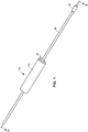
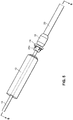
- an arterial everter device 10 of a first embodiment of the present disclosure includes an everting member 12, a hollow inflation shaft 14, and an intraluminal catheter balloon 16 disposed at a distal end of the hollow inflation shaft 14.
- the intraluminal catheter balloon 16 has a nominal deflated diameter less than a nominal inner diameter of an arterial segment 29 for which the arterial everter device 12 is to be used.
- the intraluminal catheter balloon 16 preferably has a nominal inflated diameter that is at least just greater than the nominal inner diameter of the arterial segment 29, so as to put pressure on the arterial wall when inflated, thereby providing a holding force.
- the intraluminal catheter balloon 16 may or may not accommodate over-inflation, i.e.
- An intraluminal catheter balloon 16 for use with arterial segments having a 1mm diameter preferably has a nominal deflated diameter in a range of 0.5-0.9mm and an inflated diameter of 1.5-2.5mm.
- An intraluminal catheter balloon 16 for use with arterial segments having a 3mm diameter preferably has a nominal deflated diameter in a range of 1.4-2.9mm and an inflated diameter of 3.5-4.5mm.
- the everting member 12 is longitudinally slidable along an exterior of the hollow inflation shaft 14.
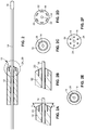
- An everter end 18 of the everting member 12 is preferably conical in shape and may have an angle ⁇ (see FIG. 2A ) between 10° and 60°. This angle of the everter end 18 may be a constant angle or, alternatively, may be a progressively changing angle.
- the everting member 12 is provided with one or more pin- or post-receiving openings 20, which may be in the form of a continuous circumferential (i.e., annular) slot (as illustrated in FIG. 2C ), or discontinuous openings 20, such as in the form of interrupted arcuate openings 22 or round openings 24 (as illustrated in FIGS. 2D, 2F , respectively) that accommodate pins or posts 30 of a coupler ring 28.
- at least a portion 26 of the everter end 18 is formed of a compliant material that deforms, such as a thermoplastic elastomer or silicone rubber (as depicted by the stippled region in FIG.
- the portion 26 of the everter end 18 may be a slideable member that axially recedes into the everter to receive the pins or posts after they move through the arterial segment.
- the coupler ring 28 is provided near a free end region 29a of an arterial segment 29 that is to be surgically coapted to another arterial segment (not shown) using microanastomosis.
- the coupler ring 28 is arranged with its pins or posts 30 directed toward the free end region 29a.
- the arterial segment 29 is part of an artery that has been clamped by a vessel clamp (not shown) upstream of the coupler ring 28 and has been irrigated.
- the arterial everter device 10 is advanced toward the arterial segment 29 until the intraluminal catheter balloon 16, while in an uninflated condition, is received in the arterial segment 29 and is disposed just beyond the coupler ring 28.
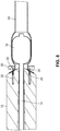
- the intraluminal catheter balloon 16 is inflated (see FIGS. 5 , 6 ).
- the intraluminal balloon 16 provides an atraumatic hard-stop for the coupler 28 so as to maintain the proper length of the free end region 29a of the arterial segment 29 to be everted over the pins or posts of the coupler ring 28; Second, the intraluminal balloon 16 opposes the axial forces placed on the free end region 29a as the everting member 12 is advanced toward the free end region 29a; and Third, the intraluminal balloon 16 minimizes the unsupported length of the free end region 29a, thereby reducing the tendency for buckling.
- the everting member 12 is advanced along the hollow inflation shaft 14 until the everter end 18 contacts the free end region 29a, with continued advancement of the everting member 12 toward the coupler ring 28 everting the free end region 29a of the arterial segment 29, as illustrated in FIG. 7 .
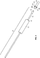
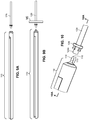
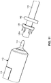
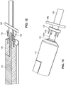
- the arterial everter device 110 includes an everting member 112 and a telescopically-mounted plunger 114.
- the telescopically-mounted plunger 114 may be made of a rigid material, such as a thermoplastic or stainless steel, a flexible material, such as a thermoplastic elastomer or silicone rubber, or a composite of rigid and flexible materials.
- a distal portion 115 of the telescopically-mounted plunger 114 may terminate in a bullet-shaped end 116.
- At least the distal portion 115 of the telescopically-mounted plunger 114 preferably has an outer diameter less than or equal to an inner diameter of the arterial segment 129 into which it is intended to be inserted.
- the arterial segment 129 is prepped for end-to-end microanastomosis by providing a coupler ring 128 near a free end 129a of the arterial segment 129, with a plurality of pins or posts 130 of the coupler ring 128 directed toward the free end 129a, and the arterial segment 129 received in the inner opening of the coupler ring 128.
- a vessel clamp VC such as a microvascular clamp, is clamped to the arterial segment 129 upstream of the coupler ring 128, the vessel clamp VC preventing the arterial segment 129 from sliding back through the coupler ring 128.
- the free end 129a is irrigated.
- the arterial everter device 110 with the telescopically-mounted plunger 114 in its fully extended position, is advanced toward, and into, the free end region 129a of the arterial segment 129 until the distal end 116 of the plunger 114 contacts an inner wall of the arterial segment at the location of the vessel clamp VC (i.e., the plunger 114 is brought into contact with arterial tissue that is abutting the vessel claim VC).
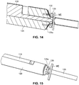
- the arterial everter device 110 is further advanced toward the free end region 129a and the coupler ring 128, due to interference with the vessel clamp VC, the plunger 114 ceases to advance along the interior of the arterial segment 129. Instead, a main body 118 of the plunger 114, which is housed within and axially slidable relative to a housing 120 of the everting member 112, effectively retracts some length of the plunger 114 into the housing 120.
- the everting member 112 includes an angled everter end 132.
- the angled everter end 132 includes one or more post- or pin-receiving openings 134, such as a continuous circumferential (i.e., annular) slot.
- the everting member 112 When the everting member 112 is sufficiently advanced toward the free end region 129a of the arterial segment 129 so as to contact the arterial tissue, the everter end 132 is further advanced toward the coupler ring 128, with the angled everter end 132 everting the free end region 129a of the arterial segment 129, as illustrated in FIGs. 14, 15 .
- the still-exposed (relative to the angled everter end 132 of the everting member 112) portion of the plunger 114 serves to maintain the shape of the arterial vessel and prevent the free end region 129a of the arterial segment 129 from bucking inward so as to permit a substantially continuous application of force annually along the coupler ring 128 to offset the tendency of the relatively thick arterial tissue to recover its natural shape and lose engagement with the pins or posts 130 of the coupler ring 128 as the arterial tissue is everted and secured to the coupler ring 128.
- the process is repeated for another arterial segment (not shown) to be coapted to the first arterial segment 129, so as to secure a free end region of that other arterial segment to a mating coupler ring (also not shown), after which the two coupler rings can be brought together to complete the end-to-end microanastomosis.
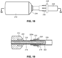
- FIGS. 16-23 A third embodiment of an arterial everter device 210 of the present disclosure is illustrated in FIGS. 16-23 .
- the device includes an everting member 212, a shaft 214 that projects distally from an everter end 232 of the everting member 212, and a radially expanding member, such as an expansion ring 216, provided along the shaft 214.
- the shaft 214 preferably includes an inner shaft 218 that is axially movable relative to an outer shaft 220, the outer shaft 220 disposed in (preferably coaxially with) the everting member 212.
- the inner shaft 218 projects distally of a distal end of the outer shaft 220.
- the shaft 214 is additionally provided with an end cap 222 disposed at, and fixed to, a distal end of the inner shaft 218.
- the expansion ring 216 is disposed between a distal end of the outer shaft 220 and a proximal end of the end cap 222.
- the expansion ring 216, or similar radially expanding member may be made of a flexible material, such as a thermoplastic elastomer or silicone rubber.
- the expanding member may alternately or additionally include a rigid material, such as a thermoplastic or stainless steel.
- the proximal end of the end cap 222 is pulled closer to the distal end of the outer shaft 220.
- This closer proximity of the end cap 222 to the distal end of the outer shaft 220 affords less axial room for the expansion ring 216 along the length of the shaft 214.
- the expansion ring 216 is compressed, whereupon it expands radially outwardly.
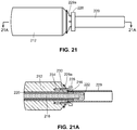
- An arterial segment 229 is prepared for microanastomosis by applying a coupler ring 228 over a free end region 229a, with the arterial vessel received in an inner opening of the coupler ring 228.
- the coupler ring 228 is provided with a plurality of posts or pins 230 that project toward the distal end of the free end region 229a.
- the everter end 232 of the everting member 212 is provided with an angled everter end 232 that includes one or more post- or pin-receiving openings 234, such as a continuous circumferential (i.e., annular) slot.
- the arterial everter device 210 is advanced toward the free end region 229a until an exposed (relative the everter end 232) portion of the shaft 214, including the end cap 222 and the expansion ring 216 are inserted into the free end region 229a, with the expansion ring 216 positioned within the inner opening of the coupler ring 228.
- the inner shaft 218 is pulled proximally so as to bring the end cap 222 closer to the distal end of the outer shaft 220, thereby causing the expansion ring 216 to expand radially outwardly, compressing the arterial vessel between the expansion ring 216 and an inner surface of the coupler ring 228.
- This expansion atraumatically holds the arterial vessel rigidly in place in relation to the coupler ring 228, while providing a supporting function that reduces the tendency of the free end region 229a to collapse, or buckle, during eversion.
- the everting member 212 With the arterial vessel rigidly secured in place, the everting member 212 is advanced toward the coupler ring 228, causing the free end region 229a to flare out over the post-or pin-receiving opening(s) 234, such as the circumferential slot, on the everter end 232.
- the posts or pins 230 Continued application of force on the everting member 212 in a direction toward the coupler ring 228 causes the posts or pins 230 to pierce through the tissue of the free end region 229a, thereby securing the arterial segment 229 to the coupler ring 228.
- the expansion ring 216 is retained in its radially expanded condition, rigidly securing the arterial vessel wall to the inner wall of the coupler ring 228, while the everter end 232 of the everting member 212 everted the free end region 229a and impales the free end region 229a on the plurality of posts or pins 230.
- the inner shaft 228 may be locked in a selected axial location relative to the outer shaft 220, such as with a bayonet-type fitting, a cam, or a threaded locking mechanism.
- a vessel clamp (not shown) could be used to grasp the arterial segment 229 just upstream of the coupler ring 228, such that the end cap 222 contacts an inner wall of arterial tissue at a location directly opposite where an outer wall of the arterial tissue is in intimate contact with the vessel clamp (in other words, the end cap 222 comes into contact with arterial tissue abutting the vessel claim), preventing further axial advancement of the end cap 222 and inner shaft 218, such that continued advancement of the everter in the direction of the arterial segment 29 pushes the outer shaft 220 toward the end cap 222, resulting in expansion of the expansion ring 216.
- the expansion ring 216 is then permitted to relax, and the everter device 210 is removed.
- the process is repeated for another arterial segment (not shown) to be coapted to the first arterial segment 229, so as to secure a free end region of that other arterial segment to a mating coupler ring (also not shown), after which the two coupler rings can be brought together to complete the end-to-end microanastomosis.
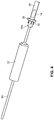
- the everter device 252 includes at least a first eversion surface 250 at a first end thereof, the eversion surface 250 being formed of a pierceable material, such as a medical grade silicone with Brinell Hardness in a range of 100-341 kgf/mm 2 (Shore A hardness between 10 and 50).
- a pierceable material such as a medical grade silicone with Brinell Hardness in a range of 100-341 kgf/mm 2 (Shore A hardness between 10 and 50.
- the exterior of the everter device 252 may be made substantially or even entirely made of the pierceable material.
- the device 252 may be provided with a supporting rod 254, such as a stainless steel rod.
- a supporting rod 254 such as a stainless steel rod.
- Other materials besides stainless steel could be utilized for the supporting rod 254, such as a rigid or semi-rigid material like a thermoplastic.
- the supporting rod 254 is made of a material that can support flexible regions of the device 252 while preventing excessive deformation during use. While the supporting rod 254 is shown as being embedded within the device 252, it will be appreciated that the supporting rod 254 may be provided on an exterior of the device 252, or may be partially embedded within the device 252 and partially on the exterior of the device 252.
- a tip of the eversion surface 250 may be made out of a flexible material such that when a vessel requires clamping or fixation behind the coupler ring, the tip can deform, thereby minimizing damage to the intima of the vessel.
- a second eversion surface 256 may be provided at a second, opposite end of the device 252.
- This second eversion surface 256 may have a different size and/or contour than the first eversion surface 250, increasing the versatility of the device 252 by permitting its use with a greater size range of vessels and couplers with a single eversion device 252.
- the device 252 may be deformable by the user, which aids in manipulating the device to a custom shape to facilitate manipulation of the device 252 in small and/or hard to reach anatomical locations.
Landscapes
- Health & Medical Sciences (AREA)
- Life Sciences & Earth Sciences (AREA)
- Heart & Thoracic Surgery (AREA)
- Surgery (AREA)
- Public Health (AREA)
- General Health & Medical Sciences (AREA)
- Engineering & Computer Science (AREA)
- Veterinary Medicine (AREA)
- Biomedical Technology (AREA)
- Animal Behavior & Ethology (AREA)
- Nuclear Medicine, Radiotherapy & Molecular Imaging (AREA)
- Medical Informatics (AREA)
- Molecular Biology (AREA)
- Hematology (AREA)
- Pulmonology (AREA)
- Biophysics (AREA)
- Anesthesiology (AREA)
- Child & Adolescent Psychology (AREA)
- Surgical Instruments (AREA)
Applications Claiming Priority (2)
| Application Number | Priority Date | Filing Date | Title |
|---|---|---|---|
| US201562214615P | 2015-09-04 | 2015-09-04 | |
| PCT/US2016/050037 WO2017040884A1 (en) | 2015-09-04 | 2016-09-02 | Device to aid in arterial microvascular anastomosis |
Publications (3)
| Publication Number | Publication Date |
|---|---|
| EP3344162A1 EP3344162A1 (en) | 2018-07-11 |
| EP3344162A4 EP3344162A4 (en) | 2019-06-12 |
| EP3344162B1 true EP3344162B1 (en) | 2021-03-10 |
Family
ID=58188482
Family Applications (1)
| Application Number | Title | Priority Date | Filing Date |
|---|---|---|---|
| EP16843041.1A Active EP3344162B1 (en) | 2015-09-04 | 2016-09-02 | Device to aid in arterial microvascular anastomosis |
Country Status (10)
| Country | Link |
|---|---|
| US (2) | US10842493B2 (zh) |
| EP (1) | EP3344162B1 (zh) |
| JP (1) | JP2018526133A (zh) |
| KR (1) | KR20180038052A (zh) |
| CN (1) | CN108024814A (zh) |
| AU (1) | AU2016315862B2 (zh) |
| CA (1) | CA2996450C (zh) |
| MX (1) | MX2018002647A (zh) |
| SG (1) | SG10201910915VA (zh) |
| WO (1) | WO2017040884A1 (zh) |
Families Citing this family (3)
| Publication number | Priority date | Publication date | Assignee | Title |
|---|---|---|---|---|
| US20220160361A1 (en) * | 2019-01-23 | 2022-05-26 | Baxter International Inc. | Eversion tool and size guide for performing arterial microvascular anastomosis |
| CN111096769A (zh) * | 2019-12-31 | 2020-05-05 | 清华大学 | 用于空腔脏器的辅助缝合装置 |
| USD972729S1 (en) * | 2021-05-05 | 2022-12-13 | Surround Medical Systems, Inc. | Detector holder coupler ring |
Family Cites Families (15)
| Publication number | Priority date | Publication date | Assignee | Title |
|---|---|---|---|---|
| US4470415A (en) | 1982-08-19 | 1984-09-11 | The Johns Hopkins University | Sutureless vascular anastomosis means and method |
| US5395331A (en) * | 1992-04-27 | 1995-03-07 | Minnesota Mining And Manufacturing Company | Retrograde coronary sinus catheter having a ribbed balloon |
| SE509388C2 (sv) * | 1996-05-17 | 1999-01-18 | Jan Otto Solem | Avgreningsanordning för ett blodkärl |
| US6599302B2 (en) * | 1998-06-10 | 2003-07-29 | Converge Medical, Inc. | Aortic aneurysm treatment systems |
| US6402764B1 (en) * | 1999-11-15 | 2002-06-11 | Cardica, Inc. | Everter and threadthrough system for attaching graft vessel to anastomosis device |
| CA2403119A1 (en) * | 2000-03-20 | 2001-09-27 | By-Pass, Inc. | Graft delivery system |
| US6547799B2 (en) * | 2001-06-26 | 2003-04-15 | Ethicon, Inc. | Vessel eversion instrument with pressurizable membrane |
| US6575985B2 (en) * | 2001-09-10 | 2003-06-10 | Ethicon, Inc. | Vessel eversion instrument with conical holder |
| US20080269784A1 (en) | 2003-12-24 | 2008-10-30 | Ryan Abbott | Anastomosis device, tools and methods of using |
| ITBO20040642A1 (it) * | 2004-10-19 | 2005-01-19 | I & S Idee & Sviluppo S R L | Giunto vascolare |
| EP1962696B1 (en) * | 2005-12-20 | 2012-03-28 | Medical Components, Inc. | Cutting balloon catheter assembly |
| JP5554722B2 (ja) * | 2008-12-25 | 2014-07-23 | 泉工医科工業株式会社 | クランプ部材、クランプ及び吻合器 |
| US9079004B2 (en) * | 2009-11-17 | 2015-07-14 | C. R. Bard, Inc. | Overmolded access port including anchoring and identification features |
| EP2558004A4 (en) * | 2010-04-16 | 2015-04-29 | Univ Utah Res Found | METHODS, DEVICES, AND APPARATUS FOR REALIZING VASCULAR ANASTOMOSIS |
| EP2651314B1 (en) * | 2010-12-15 | 2018-07-18 | Colospan Ltd. | Systems for bypassing an anastomosis site |
-
2016
- 2016-09-02 AU AU2016315862A patent/AU2016315862B2/en not_active Ceased
- 2016-09-02 KR KR1020187008291A patent/KR20180038052A/ko unknown
- 2016-09-02 JP JP2018511749A patent/JP2018526133A/ja active Pending
- 2016-09-02 US US15/755,506 patent/US10842493B2/en active Active
- 2016-09-02 MX MX2018002647A patent/MX2018002647A/es unknown
- 2016-09-02 CN CN201680050903.8A patent/CN108024814A/zh active Pending
- 2016-09-02 SG SG10201910915VA patent/SG10201910915VA/en unknown
- 2016-09-02 CA CA2996450A patent/CA2996450C/en not_active Expired - Fee Related
- 2016-09-02 WO PCT/US2016/050037 patent/WO2017040884A1/en active Application Filing
- 2016-09-02 EP EP16843041.1A patent/EP3344162B1/en active Active
-
2020
- 2020-10-20 US US17/075,339 patent/US20210030418A1/en not_active Abandoned
Non-Patent Citations (1)
| Title |
|---|
| None * |
Also Published As
| Publication number | Publication date |
|---|---|
| CN108024814A (zh) | 2018-05-11 |
| EP3344162A1 (en) | 2018-07-11 |
| CA2996450C (en) | 2021-02-16 |
| MX2018002647A (es) | 2018-11-09 |
| JP2018526133A (ja) | 2018-09-13 |
| AU2016315862A1 (en) | 2018-03-08 |
| SG10201910915VA (en) | 2020-01-30 |
| US10842493B2 (en) | 2020-11-24 |
| US20180271529A1 (en) | 2018-09-27 |
| WO2017040884A1 (en) | 2017-03-09 |
| NZ739943A (en) | 2021-01-29 |
| US20210030418A1 (en) | 2021-02-04 |
| AU2016315862B2 (en) | 2020-11-26 |
| CA2996450A1 (en) | 2017-03-09 |
| KR20180038052A (ko) | 2018-04-13 |
| EP3344162A4 (en) | 2019-06-12 |
Similar Documents
| Publication | Publication Date | Title |
|---|---|---|
| US20210030418A1 (en) | Device to aid in arterial microvascular anastomosis | |
| US7648515B2 (en) | Method and apparatus for anastomosis including an expandable anchor | |
| US6712831B1 (en) | Methods and apparatus for forming anastomotic sites | |
| US8480694B2 (en) | Method and apparatus for anastomosis including an expandable anchor | |
| US7744527B2 (en) | Surgical coring system | |
| US6920882B2 (en) | Medical grafting methods and apparatus | |
| JP2647259B2 (ja) | 背静脈結紮を実施する方法及び装置 | |
| US20040215233A1 (en) | Methods and apparatus for forming anastomotic sites | |
| US6596003B1 (en) | Vascular anastomosis device | |
| JP2007517598A (ja) | 植込型デバイスのための縫着デバイス | |
| JP2018526133A5 (zh) | ||
| EP1648309A1 (en) | Methods and apparatus for forming anastomotic sites | |
| NZ739943B2 (en) | Device to aid in arterial microvascular anastomosis | |
| WO2021105870A1 (en) | Device for aiding the operation of a circular, mechanical, surgical stapler and kit for surgery by means of a circular, mechanical, surgical stapler | |
| EP3048995A1 (en) | A device and method for suturing hollow organs | |
| AU2003279113B2 (en) | Method and apparatus for anastomosis including an anchoring sleeve | |
| AU2013200266A1 (en) | Surgical tools for lvad implantation | |
| AU2003279113A1 (en) | Method and apparatus for anastomosis including an anchoring sleeve |
Legal Events
| Date | Code | Title | Description |
|---|---|---|---|
| STAA | Information on the status of an ep patent application or granted ep patent |
Free format text: STATUS: THE INTERNATIONAL PUBLICATION HAS BEEN MADE |
|
| PUAI | Public reference made under article 153(3) epc to a published international application that has entered the european phase |
Free format text: ORIGINAL CODE: 0009012 |
|
| STAA | Information on the status of an ep patent application or granted ep patent |
Free format text: STATUS: REQUEST FOR EXAMINATION WAS MADE |
|
| 17P | Request for examination filed |
Effective date: 20180329 |
|
| AK | Designated contracting states |
Kind code of ref document: A1 Designated state(s): AL AT BE BG CH CY CZ DE DK EE ES FI FR GB GR HR HU IE IS IT LI LT LU LV MC MK MT NL NO PL PT RO RS SE SI SK SM TR |
|
| AX | Request for extension of the european patent |
Extension state: BA ME |
|
| DAV | Request for validation of the european patent (deleted) | ||
| DAX | Request for extension of the european patent (deleted) | ||
| A4 | Supplementary search report drawn up and despatched |
Effective date: 20190513 |
|
| RIC1 | Information provided on ipc code assigned before grant |
Ipc: A61B 17/064 20060101ALN20190507BHEP Ipc: A61M 25/10 20130101ALI20190507BHEP Ipc: A61B 17/22 20060101ALN20190507BHEP Ipc: A61B 17/00 20060101ALN20190507BHEP Ipc: A61B 17/11 20060101AFI20190507BHEP |
|
| RIC1 | Information provided on ipc code assigned before grant |
Ipc: A61B 17/00 20060101ALN20200527BHEP Ipc: A61B 17/11 20060101AFI20200527BHEP Ipc: A61B 17/22 20060101ALN20200527BHEP Ipc: A61M 25/10 20130101ALI20200527BHEP Ipc: A61B 17/064 20060101ALN20200527BHEP |
|
| GRAP | Despatch of communication of intention to grant a patent |
Free format text: ORIGINAL CODE: EPIDOSNIGR1 |
|
| STAA | Information on the status of an ep patent application or granted ep patent |
Free format text: STATUS: GRANT OF PATENT IS INTENDED |
|
| RIC1 | Information provided on ipc code assigned before grant |
Ipc: A61B 17/11 20060101AFI20200608BHEP Ipc: A61B 17/00 20060101ALN20200608BHEP Ipc: A61B 17/22 20060101ALN20200608BHEP Ipc: A61B 17/064 20060101ALN20200608BHEP Ipc: A61M 25/10 20130101ALI20200608BHEP |
|
| INTG | Intention to grant announced |
Effective date: 20200706 |
|
| GRAJ | Information related to disapproval of communication of intention to grant by the applicant or resumption of examination proceedings by the epo deleted |
Free format text: ORIGINAL CODE: EPIDOSDIGR1 |
|
| STAA | Information on the status of an ep patent application or granted ep patent |
Free format text: STATUS: REQUEST FOR EXAMINATION WAS MADE |
|
| GRAP | Despatch of communication of intention to grant a patent |
Free format text: ORIGINAL CODE: EPIDOSNIGR1 |
|
| STAA | Information on the status of an ep patent application or granted ep patent |
Free format text: STATUS: GRANT OF PATENT IS INTENDED |
|
| INTC | Intention to grant announced (deleted) | ||
| RIC1 | Information provided on ipc code assigned before grant |
Ipc: A61B 17/064 20060101ALN20200923BHEP Ipc: A61M 25/10 20130101ALI20200923BHEP Ipc: A61B 17/22 20060101ALN20200923BHEP Ipc: A61B 17/00 20060101ALN20200923BHEP Ipc: A61B 17/11 20060101AFI20200923BHEP |
|
| INTG | Intention to grant announced |
Effective date: 20201015 |
|
| GRAS | Grant fee paid |
Free format text: ORIGINAL CODE: EPIDOSNIGR3 |
|
| STAA | Information on the status of an ep patent application or granted ep patent |
Free format text: STATUS: GRANT OF PATENT IS INTENDED |
|
| GRAA | (expected) grant |
Free format text: ORIGINAL CODE: 0009210 |
|
| STAA | Information on the status of an ep patent application or granted ep patent |
Free format text: STATUS: THE PATENT HAS BEEN GRANTED |
|
| AK | Designated contracting states |
Kind code of ref document: B1 Designated state(s): AL AT BE BG CH CY CZ DE DK EE ES FI FR GB GR HR HU IE IS IT LI LT LU LV MC MK MT NL NO PL PT RO RS SE SI SK SM TR |
|
| REG | Reference to a national code |
Ref country code: GB Ref legal event code: FG4D |
|
| REG | Reference to a national code |
Ref country code: AT Ref legal event code: REF Ref document number: 1368912 Country of ref document: AT Kind code of ref document: T Effective date: 20210315 Ref country code: CH Ref legal event code: EP |
|
| REG | Reference to a national code |
Ref country code: IE Ref legal event code: FG4D |
|
| REG | Reference to a national code |
Ref country code: DE Ref legal event code: R096 Ref document number: 602016054180 Country of ref document: DE |
|
| REG | Reference to a national code |
Ref country code: LT Ref legal event code: MG9D |
|
| PG25 | Lapsed in a contracting state [announced via postgrant information from national office to epo] |
Ref country code: FI Free format text: LAPSE BECAUSE OF FAILURE TO SUBMIT A TRANSLATION OF THE DESCRIPTION OR TO PAY THE FEE WITHIN THE PRESCRIBED TIME-LIMIT Effective date: 20210310 Ref country code: GR Free format text: LAPSE BECAUSE OF FAILURE TO SUBMIT A TRANSLATION OF THE DESCRIPTION OR TO PAY THE FEE WITHIN THE PRESCRIBED TIME-LIMIT Effective date: 20210611 Ref country code: HR Free format text: LAPSE BECAUSE OF FAILURE TO SUBMIT A TRANSLATION OF THE DESCRIPTION OR TO PAY THE FEE WITHIN THE PRESCRIBED TIME-LIMIT Effective date: 20210310 Ref country code: NO Free format text: LAPSE BECAUSE OF FAILURE TO SUBMIT A TRANSLATION OF THE DESCRIPTION OR TO PAY THE FEE WITHIN THE PRESCRIBED TIME-LIMIT Effective date: 20210610 Ref country code: LT Free format text: LAPSE BECAUSE OF FAILURE TO SUBMIT A TRANSLATION OF THE DESCRIPTION OR TO PAY THE FEE WITHIN THE PRESCRIBED TIME-LIMIT Effective date: 20210310 Ref country code: BG Free format text: LAPSE BECAUSE OF FAILURE TO SUBMIT A TRANSLATION OF THE DESCRIPTION OR TO PAY THE FEE WITHIN THE PRESCRIBED TIME-LIMIT Effective date: 20210610 |
|
| REG | Reference to a national code |
Ref country code: AT Ref legal event code: MK05 Ref document number: 1368912 Country of ref document: AT Kind code of ref document: T Effective date: 20210310 |
|
| REG | Reference to a national code |
Ref country code: NL Ref legal event code: MP Effective date: 20210310 |
|
| PG25 | Lapsed in a contracting state [announced via postgrant information from national office to epo] |
Ref country code: SE Free format text: LAPSE BECAUSE OF FAILURE TO SUBMIT A TRANSLATION OF THE DESCRIPTION OR TO PAY THE FEE WITHIN THE PRESCRIBED TIME-LIMIT Effective date: 20210310 Ref country code: LV Free format text: LAPSE BECAUSE OF FAILURE TO SUBMIT A TRANSLATION OF THE DESCRIPTION OR TO PAY THE FEE WITHIN THE PRESCRIBED TIME-LIMIT Effective date: 20210310 Ref country code: RS Free format text: LAPSE BECAUSE OF FAILURE TO SUBMIT A TRANSLATION OF THE DESCRIPTION OR TO PAY THE FEE WITHIN THE PRESCRIBED TIME-LIMIT Effective date: 20210310 |
|
| PG25 | Lapsed in a contracting state [announced via postgrant information from national office to epo] |
Ref country code: NL Free format text: LAPSE BECAUSE OF FAILURE TO SUBMIT A TRANSLATION OF THE DESCRIPTION OR TO PAY THE FEE WITHIN THE PRESCRIBED TIME-LIMIT Effective date: 20210310 |
|
| PG25 | Lapsed in a contracting state [announced via postgrant information from national office to epo] |
Ref country code: EE Free format text: LAPSE BECAUSE OF FAILURE TO SUBMIT A TRANSLATION OF THE DESCRIPTION OR TO PAY THE FEE WITHIN THE PRESCRIBED TIME-LIMIT Effective date: 20210310 Ref country code: CZ Free format text: LAPSE BECAUSE OF FAILURE TO SUBMIT A TRANSLATION OF THE DESCRIPTION OR TO PAY THE FEE WITHIN THE PRESCRIBED TIME-LIMIT Effective date: 20210310 Ref country code: AT Free format text: LAPSE BECAUSE OF FAILURE TO SUBMIT A TRANSLATION OF THE DESCRIPTION OR TO PAY THE FEE WITHIN THE PRESCRIBED TIME-LIMIT Effective date: 20210310 Ref country code: SM Free format text: LAPSE BECAUSE OF FAILURE TO SUBMIT A TRANSLATION OF THE DESCRIPTION OR TO PAY THE FEE WITHIN THE PRESCRIBED TIME-LIMIT Effective date: 20210310 |
|
| PGFP | Annual fee paid to national office [announced via postgrant information from national office to epo] |
Ref country code: FR Payment date: 20210927 Year of fee payment: 6 |
|
| PG25 | Lapsed in a contracting state [announced via postgrant information from national office to epo] |
Ref country code: PL Free format text: LAPSE BECAUSE OF FAILURE TO SUBMIT A TRANSLATION OF THE DESCRIPTION OR TO PAY THE FEE WITHIN THE PRESCRIBED TIME-LIMIT Effective date: 20210310 Ref country code: PT Free format text: LAPSE BECAUSE OF FAILURE TO SUBMIT A TRANSLATION OF THE DESCRIPTION OR TO PAY THE FEE WITHIN THE PRESCRIBED TIME-LIMIT Effective date: 20210712 Ref country code: RO Free format text: LAPSE BECAUSE OF FAILURE TO SUBMIT A TRANSLATION OF THE DESCRIPTION OR TO PAY THE FEE WITHIN THE PRESCRIBED TIME-LIMIT Effective date: 20210310 Ref country code: SK Free format text: LAPSE BECAUSE OF FAILURE TO SUBMIT A TRANSLATION OF THE DESCRIPTION OR TO PAY THE FEE WITHIN THE PRESCRIBED TIME-LIMIT Effective date: 20210310 Ref country code: IS Free format text: LAPSE BECAUSE OF FAILURE TO SUBMIT A TRANSLATION OF THE DESCRIPTION OR TO PAY THE FEE WITHIN THE PRESCRIBED TIME-LIMIT Effective date: 20210710 |
|
| PGFP | Annual fee paid to national office [announced via postgrant information from national office to epo] |
Ref country code: DE Payment date: 20210921 Year of fee payment: 6 Ref country code: GB Payment date: 20210820 Year of fee payment: 6 |
|
| REG | Reference to a national code |
Ref country code: DE Ref legal event code: R097 Ref document number: 602016054180 Country of ref document: DE |
|
| PLBE | No opposition filed within time limit |
Free format text: ORIGINAL CODE: 0009261 |
|
| STAA | Information on the status of an ep patent application or granted ep patent |
Free format text: STATUS: NO OPPOSITION FILED WITHIN TIME LIMIT |
|
| PG25 | Lapsed in a contracting state [announced via postgrant information from national office to epo] |
Ref country code: DK Free format text: LAPSE BECAUSE OF FAILURE TO SUBMIT A TRANSLATION OF THE DESCRIPTION OR TO PAY THE FEE WITHIN THE PRESCRIBED TIME-LIMIT Effective date: 20210310 Ref country code: AL Free format text: LAPSE BECAUSE OF FAILURE TO SUBMIT A TRANSLATION OF THE DESCRIPTION OR TO PAY THE FEE WITHIN THE PRESCRIBED TIME-LIMIT Effective date: 20210310 Ref country code: ES Free format text: LAPSE BECAUSE OF FAILURE TO SUBMIT A TRANSLATION OF THE DESCRIPTION OR TO PAY THE FEE WITHIN THE PRESCRIBED TIME-LIMIT Effective date: 20210310 |
|
| 26N | No opposition filed |
Effective date: 20211213 |
|
| PG25 | Lapsed in a contracting state [announced via postgrant information from national office to epo] |
Ref country code: SI Free format text: LAPSE BECAUSE OF FAILURE TO SUBMIT A TRANSLATION OF THE DESCRIPTION OR TO PAY THE FEE WITHIN THE PRESCRIBED TIME-LIMIT Effective date: 20210310 |
|
| PG25 | Lapsed in a contracting state [announced via postgrant information from national office to epo] |
Ref country code: IT Free format text: LAPSE BECAUSE OF FAILURE TO SUBMIT A TRANSLATION OF THE DESCRIPTION OR TO PAY THE FEE WITHIN THE PRESCRIBED TIME-LIMIT Effective date: 20210310 |
|
| REG | Reference to a national code |
Ref country code: CH Ref legal event code: PL |
|
| REG | Reference to a national code |
Ref country code: BE Ref legal event code: MM Effective date: 20210930 |
|
| PG25 | Lapsed in a contracting state [announced via postgrant information from national office to epo] |
Ref country code: IS Free format text: LAPSE BECAUSE OF FAILURE TO SUBMIT A TRANSLATION OF THE DESCRIPTION OR TO PAY THE FEE WITHIN THE PRESCRIBED TIME-LIMIT Effective date: 20210710 Ref country code: MC Free format text: LAPSE BECAUSE OF FAILURE TO SUBMIT A TRANSLATION OF THE DESCRIPTION OR TO PAY THE FEE WITHIN THE PRESCRIBED TIME-LIMIT Effective date: 20210310 |
|
| PG25 | Lapsed in a contracting state [announced via postgrant information from national office to epo] |
Ref country code: LU Free format text: LAPSE BECAUSE OF NON-PAYMENT OF DUE FEES Effective date: 20210902 Ref country code: IE Free format text: LAPSE BECAUSE OF NON-PAYMENT OF DUE FEES Effective date: 20210902 Ref country code: BE Free format text: LAPSE BECAUSE OF NON-PAYMENT OF DUE FEES Effective date: 20210930 |
|
| PG25 | Lapsed in a contracting state [announced via postgrant information from national office to epo] |
Ref country code: LI Free format text: LAPSE BECAUSE OF NON-PAYMENT OF DUE FEES Effective date: 20210930 Ref country code: CH Free format text: LAPSE BECAUSE OF NON-PAYMENT OF DUE FEES Effective date: 20210930 |
|
| REG | Reference to a national code |
Ref country code: DE Ref legal event code: R119 Ref document number: 602016054180 Country of ref document: DE |
|
| GBPC | Gb: european patent ceased through non-payment of renewal fee |
Effective date: 20220902 |
|
| PG25 | Lapsed in a contracting state [announced via postgrant information from national office to epo] |
Ref country code: HU Free format text: LAPSE BECAUSE OF FAILURE TO SUBMIT A TRANSLATION OF THE DESCRIPTION OR TO PAY THE FEE WITHIN THE PRESCRIBED TIME-LIMIT; INVALID AB INITIO Effective date: 20160902 |
|
| P01 | Opt-out of the competence of the unified patent court (upc) registered |
Effective date: 20230509 |
|
| PG25 | Lapsed in a contracting state [announced via postgrant information from national office to epo] |
Ref country code: CY Free format text: LAPSE BECAUSE OF FAILURE TO SUBMIT A TRANSLATION OF THE DESCRIPTION OR TO PAY THE FEE WITHIN THE PRESCRIBED TIME-LIMIT Effective date: 20210310 |
|
| PG25 | Lapsed in a contracting state [announced via postgrant information from national office to epo] |
Ref country code: FR Free format text: LAPSE BECAUSE OF NON-PAYMENT OF DUE FEES Effective date: 20220930 Ref country code: DE Free format text: LAPSE BECAUSE OF NON-PAYMENT OF DUE FEES Effective date: 20230401 |
|
| PG25 | Lapsed in a contracting state [announced via postgrant information from national office to epo] |
Ref country code: GB Free format text: LAPSE BECAUSE OF NON-PAYMENT OF DUE FEES Effective date: 20220902 |
|
| PG25 | Lapsed in a contracting state [announced via postgrant information from national office to epo] |
Ref country code: MK Free format text: LAPSE BECAUSE OF FAILURE TO SUBMIT A TRANSLATION OF THE DESCRIPTION OR TO PAY THE FEE WITHIN THE PRESCRIBED TIME-LIMIT Effective date: 20210310 |