EP3343688B1 - Method for manufacturing battery cell including reference electrode for measurement of relative electrode potential and battery cell manufactured thereby - Google Patents
Method for manufacturing battery cell including reference electrode for measurement of relative electrode potential and battery cell manufactured thereby Download PDFInfo
- Publication number
- EP3343688B1 EP3343688B1 EP16839499.7A EP16839499A EP3343688B1 EP 3343688 B1 EP3343688 B1 EP 3343688B1 EP 16839499 A EP16839499 A EP 16839499A EP 3343688 B1 EP3343688 B1 EP 3343688B1
- Authority
- EP
- European Patent Office
- Prior art keywords
- electrode
- lithium
- potential
- battery cell
- formation
- Prior art date
- Legal status (The legal status is an assumption and is not a legal conclusion. Google has not performed a legal analysis and makes no representation as to the accuracy of the status listed.)
- Active
Links
- 238000000034 method Methods 0.000 title claims description 49
- 238000004519 manufacturing process Methods 0.000 title claims description 17
- 238000005259 measurement Methods 0.000 title description 12
- 230000015572 biosynthetic process Effects 0.000 claims description 36
- 229910052744 lithium Inorganic materials 0.000 claims description 36
- WHXSMMKQMYFTQS-UHFFFAOYSA-N Lithium Chemical compound [Li] WHXSMMKQMYFTQS-UHFFFAOYSA-N 0.000 claims description 35
- 230000008569 process Effects 0.000 claims description 21
- 238000000926 separation method Methods 0.000 claims description 21
- 229910001416 lithium ion Inorganic materials 0.000 claims description 17
- 239000007772 electrode material Substances 0.000 claims description 16
- HBBGRARXTFLTSG-UHFFFAOYSA-N Lithium ion Chemical compound [Li+] HBBGRARXTFLTSG-UHFFFAOYSA-N 0.000 claims description 15
- 239000008151 electrolyte solution Substances 0.000 claims description 11
- 229910052782 aluminium Inorganic materials 0.000 claims description 10
- 239000010949 copper Substances 0.000 claims description 9
- FDLZQPXZHIFURF-UHFFFAOYSA-N [O-2].[Ti+4].[Li+] Chemical compound [O-2].[Ti+4].[Li+] FDLZQPXZHIFURF-UHFFFAOYSA-N 0.000 claims description 7
- XAGFODPZIPBFFR-UHFFFAOYSA-N aluminium Chemical compound [Al] XAGFODPZIPBFFR-UHFFFAOYSA-N 0.000 claims description 7
- 229910052802 copper Inorganic materials 0.000 claims description 7
- 239000007773 negative electrode material Substances 0.000 claims description 7
- RYGMFSIKBFXOCR-UHFFFAOYSA-N Copper Chemical compound [Cu] RYGMFSIKBFXOCR-UHFFFAOYSA-N 0.000 claims description 6
- 230000005012 migration Effects 0.000 claims description 6
- 238000013508 migration Methods 0.000 claims description 6
- 239000011347 resin Substances 0.000 claims description 6
- 229920005989 resin Polymers 0.000 claims description 6
- 238000007599 discharging Methods 0.000 claims description 5
- 239000010408 film Substances 0.000 description 23
- -1 LiV3O8 Chemical class 0.000 description 18
- 229920000642 polymer Polymers 0.000 description 13
- OKTJSMMVPCPJKN-UHFFFAOYSA-N Carbon Chemical compound [C] OKTJSMMVPCPJKN-UHFFFAOYSA-N 0.000 description 12
- 238000001994 activation Methods 0.000 description 12
- PXHVJJICTQNCMI-UHFFFAOYSA-N Nickel Chemical compound [Ni] PXHVJJICTQNCMI-UHFFFAOYSA-N 0.000 description 11
- 230000008859 change Effects 0.000 description 11
- 239000000126 substance Substances 0.000 description 9
- 239000000203 mixture Substances 0.000 description 8
- 238000003487 electrochemical reaction Methods 0.000 description 7
- 239000011255 nonaqueous electrolyte Substances 0.000 description 7
- SECXISVLQFMRJM-UHFFFAOYSA-N N-Methylpyrrolidone Chemical compound CN1CCCC1=O SECXISVLQFMRJM-UHFFFAOYSA-N 0.000 description 6
- 239000011230 binding agent Substances 0.000 description 6
- 229910052799 carbon Inorganic materials 0.000 description 6
- 229910003002 lithium salt Inorganic materials 0.000 description 6
- 159000000002 lithium salts Chemical class 0.000 description 6
- 229910052759 nickel Inorganic materials 0.000 description 6
- 239000007774 positive electrode material Substances 0.000 description 6
- 239000007784 solid electrolyte Substances 0.000 description 6
- 239000011248 coating agent Substances 0.000 description 5
- 238000000576 coating method Methods 0.000 description 5
- 239000004020 conductor Substances 0.000 description 5
- 239000002904 solvent Substances 0.000 description 5
- 239000004698 Polyethylene Substances 0.000 description 4
- RTAQQCXQSZGOHL-UHFFFAOYSA-N Titanium Chemical compound [Ti] RTAQQCXQSZGOHL-UHFFFAOYSA-N 0.000 description 4
- 230000003213 activating effect Effects 0.000 description 4
- 239000002131 composite material Substances 0.000 description 4
- 229910052742 iron Inorganic materials 0.000 description 4
- XEEYBQQBJWHFJM-UHFFFAOYSA-N iron Substances [Fe] XEEYBQQBJWHFJM-UHFFFAOYSA-N 0.000 description 4
- 239000000463 material Substances 0.000 description 4
- 229920000573 polyethylene Polymers 0.000 description 4
- 239000002002 slurry Substances 0.000 description 4
- 229910001220 stainless steel Inorganic materials 0.000 description 4
- 239000010935 stainless steel Substances 0.000 description 4
- 229910052719 titanium Inorganic materials 0.000 description 4
- 239000010936 titanium Substances 0.000 description 4
- WEVYAHXRMPXWCK-UHFFFAOYSA-N Acetonitrile Chemical compound CC#N WEVYAHXRMPXWCK-UHFFFAOYSA-N 0.000 description 3
- 239000006245 Carbon black Super-P Substances 0.000 description 3
- ZMXDDKWLCZADIW-UHFFFAOYSA-N N,N-Dimethylformamide Chemical compound CN(C)C=O ZMXDDKWLCZADIW-UHFFFAOYSA-N 0.000 description 3
- 239000004743 Polypropylene Substances 0.000 description 3
- 230000015556 catabolic process Effects 0.000 description 3
- 239000006258 conductive agent Substances 0.000 description 3
- 230000003247 decreasing effect Effects 0.000 description 3
- 238000006731 degradation reaction Methods 0.000 description 3
- 210000003298 dental enamel Anatomy 0.000 description 3
- 239000011888 foil Substances 0.000 description 3
- 239000003365 glass fiber Substances 0.000 description 3
- 239000004745 nonwoven fabric Substances 0.000 description 3
- 229920001155 polypropylene Polymers 0.000 description 3
- WNXJIVFYUVYPPR-UHFFFAOYSA-N 1,3-dioxolane Chemical compound C1COCO1 WNXJIVFYUVYPPR-UHFFFAOYSA-N 0.000 description 2
- YEJRWHAVMIAJKC-UHFFFAOYSA-N 4-Butyrolactone Chemical compound O=C1CCCO1 YEJRWHAVMIAJKC-UHFFFAOYSA-N 0.000 description 2
- SBLRHMKNNHXPHG-UHFFFAOYSA-N 4-fluoro-1,3-dioxolan-2-one Chemical compound FC1COC(=O)O1 SBLRHMKNNHXPHG-UHFFFAOYSA-N 0.000 description 2
- 229920000049 Carbon (fiber) Polymers 0.000 description 2
- CURLTUGMZLYLDI-UHFFFAOYSA-N Carbon dioxide Chemical compound O=C=O CURLTUGMZLYLDI-UHFFFAOYSA-N 0.000 description 2
- BVKZGUZCCUSVTD-UHFFFAOYSA-L Carbonate Chemical compound [O-]C([O-])=O BVKZGUZCCUSVTD-UHFFFAOYSA-L 0.000 description 2
- RTZKZFJDLAIYFH-UHFFFAOYSA-N Diethyl ether Chemical compound CCOCC RTZKZFJDLAIYFH-UHFFFAOYSA-N 0.000 description 2
- XTHFKEDIFFGKHM-UHFFFAOYSA-N Dimethoxyethane Chemical compound COCCOC XTHFKEDIFFGKHM-UHFFFAOYSA-N 0.000 description 2
- IAZDPXIOMUYVGZ-UHFFFAOYSA-N Dimethylsulphoxide Chemical compound CS(C)=O IAZDPXIOMUYVGZ-UHFFFAOYSA-N 0.000 description 2
- 229920002943 EPDM rubber Polymers 0.000 description 2
- ZHNUHDYFZUAESO-UHFFFAOYSA-N Formamide Chemical compound NC=O ZHNUHDYFZUAESO-UHFFFAOYSA-N 0.000 description 2
- 229910001290 LiPF6 Inorganic materials 0.000 description 2
- 229910019142 PO4 Inorganic materials 0.000 description 2
- 239000004372 Polyvinyl alcohol Substances 0.000 description 2
- JUJWROOIHBZHMG-UHFFFAOYSA-N Pyridine Chemical compound C1=CC=NC=C1 JUJWROOIHBZHMG-UHFFFAOYSA-N 0.000 description 2
- KAESVJOAVNADME-UHFFFAOYSA-N Pyrrole Chemical class C=1C=CNC=1 KAESVJOAVNADME-UHFFFAOYSA-N 0.000 description 2
- XLOMVQKBTHCTTD-UHFFFAOYSA-N Zinc monoxide Chemical compound [Zn]=O XLOMVQKBTHCTTD-UHFFFAOYSA-N 0.000 description 2
- 230000004913 activation Effects 0.000 description 2
- 150000001336 alkenes Chemical class 0.000 description 2
- 229910045601 alloy Inorganic materials 0.000 description 2
- 239000000956 alloy Substances 0.000 description 2
- 229910021383 artificial graphite Inorganic materials 0.000 description 2
- 230000008901 benefit Effects 0.000 description 2
- WMWLMWRWZQELOS-UHFFFAOYSA-N bismuth(iii) oxide Chemical compound O=[Bi]O[Bi]=O WMWLMWRWZQELOS-UHFFFAOYSA-N 0.000 description 2
- 229910052796 boron Inorganic materials 0.000 description 2
- 239000004917 carbon fiber Substances 0.000 description 2
- 150000001875 compounds Chemical group 0.000 description 2
- IEJIGPNLZYLLBP-UHFFFAOYSA-N dimethyl carbonate Chemical compound COC(=O)OC IEJIGPNLZYLLBP-UHFFFAOYSA-N 0.000 description 2
- GNTDGMZSJNCJKK-UHFFFAOYSA-N divanadium pentaoxide Chemical compound O=[V](=O)O[V](=O)=O GNTDGMZSJNCJKK-UHFFFAOYSA-N 0.000 description 2
- 238000001035 drying Methods 0.000 description 2
- 238000010292 electrical insulation Methods 0.000 description 2
- FKRCODPIKNYEAC-UHFFFAOYSA-N ethyl propionate Chemical compound CCOC(=O)CC FKRCODPIKNYEAC-UHFFFAOYSA-N 0.000 description 2
- LYCAIKOWRPUZTN-UHFFFAOYSA-N ethylene glycol Natural products OCCO LYCAIKOWRPUZTN-UHFFFAOYSA-N 0.000 description 2
- 239000000835 fiber Substances 0.000 description 2
- 239000002657 fibrous material Substances 0.000 description 2
- 239000000945 filler Substances 0.000 description 2
- 239000006260 foam Substances 0.000 description 2
- YBMRDBCBODYGJE-UHFFFAOYSA-N germanium dioxide Chemical compound O=[Ge]=O YBMRDBCBODYGJE-UHFFFAOYSA-N 0.000 description 2
- 229910002804 graphite Inorganic materials 0.000 description 2
- 239000010439 graphite Substances 0.000 description 2
- 229910052736 halogen Inorganic materials 0.000 description 2
- 150000002367 halogens Chemical class 0.000 description 2
- 229910003480 inorganic solid Inorganic materials 0.000 description 2
- AMXOYNBUYSYVKV-UHFFFAOYSA-M lithium bromide Chemical compound [Li+].[Br-] AMXOYNBUYSYVKV-UHFFFAOYSA-M 0.000 description 2
- KWGKDLIKAYFUFQ-UHFFFAOYSA-M lithium chloride Chemical compound [Li+].[Cl-] KWGKDLIKAYFUFQ-UHFFFAOYSA-M 0.000 description 2
- 229910000625 lithium cobalt oxide Inorganic materials 0.000 description 2
- MHCFAGZWMAWTNR-UHFFFAOYSA-M lithium perchlorate Chemical compound [Li+].[O-]Cl(=O)(=O)=O MHCFAGZWMAWTNR-UHFFFAOYSA-M 0.000 description 2
- 229910001486 lithium perchlorate Inorganic materials 0.000 description 2
- 229910001496 lithium tetrafluoroborate Inorganic materials 0.000 description 2
- BFZPBUKRYWOWDV-UHFFFAOYSA-N lithium;oxido(oxo)cobalt Chemical compound [Li+].[O-][Co]=O BFZPBUKRYWOWDV-UHFFFAOYSA-N 0.000 description 2
- 229910052748 manganese Inorganic materials 0.000 description 2
- 239000011572 manganese Substances 0.000 description 2
- 238000000691 measurement method Methods 0.000 description 2
- 229910052751 metal Inorganic materials 0.000 description 2
- 239000002184 metal Substances 0.000 description 2
- 229910044991 metal oxide Inorganic materials 0.000 description 2
- 150000004706 metal oxides Chemical class 0.000 description 2
- VNWKTOKETHGBQD-UHFFFAOYSA-N methane Chemical compound C VNWKTOKETHGBQD-UHFFFAOYSA-N 0.000 description 2
- TZIHFWKZFHZASV-UHFFFAOYSA-N methyl formate Chemical compound COC=O TZIHFWKZFHZASV-UHFFFAOYSA-N 0.000 description 2
- 229910021382 natural graphite Inorganic materials 0.000 description 2
- 239000011356 non-aqueous organic solvent Substances 0.000 description 2
- JRZJOMJEPLMPRA-UHFFFAOYSA-N olefin Natural products CCCCCCCC=C JRZJOMJEPLMPRA-UHFFFAOYSA-N 0.000 description 2
- 239000010452 phosphate Substances 0.000 description 2
- 239000004417 polycarbonate Substances 0.000 description 2
- 229920000728 polyester Polymers 0.000 description 2
- 229920002451 polyvinyl alcohol Polymers 0.000 description 2
- 235000019422 polyvinyl alcohol Nutrition 0.000 description 2
- RUOJZAUFBMNUDX-UHFFFAOYSA-N propylene carbonate Chemical compound CC1COC(=O)O1 RUOJZAUFBMNUDX-UHFFFAOYSA-N 0.000 description 2
- 230000002441 reversible effect Effects 0.000 description 2
- 238000007789 sealing Methods 0.000 description 2
- 229910052710 silicon Inorganic materials 0.000 description 2
- 239000000243 solution Substances 0.000 description 2
- 229920003048 styrene butadiene rubber Polymers 0.000 description 2
- VZGDMQKNWNREIO-UHFFFAOYSA-N tetrachloromethane Chemical compound ClC(Cl)(Cl)Cl VZGDMQKNWNREIO-UHFFFAOYSA-N 0.000 description 2
- XOLBLPGZBRYERU-UHFFFAOYSA-N tin dioxide Chemical compound O=[Sn]=O XOLBLPGZBRYERU-UHFFFAOYSA-N 0.000 description 2
- PYOKUURKVVELLB-UHFFFAOYSA-N trimethyl orthoformate Chemical compound COC(OC)OC PYOKUURKVVELLB-UHFFFAOYSA-N 0.000 description 2
- 229910052725 zinc Inorganic materials 0.000 description 2
- 239000011701 zinc Substances 0.000 description 2
- MIZLGWKEZAPEFJ-UHFFFAOYSA-N 1,1,2-trifluoroethene Chemical compound FC=C(F)F MIZLGWKEZAPEFJ-UHFFFAOYSA-N 0.000 description 1
- ZZXUZKXVROWEIF-UHFFFAOYSA-N 1,2-butylene carbonate Chemical compound CCC1COC(=O)O1 ZZXUZKXVROWEIF-UHFFFAOYSA-N 0.000 description 1
- CYSGHNMQYZDMIA-UHFFFAOYSA-N 1,3-Dimethyl-2-imidazolidinon Chemical compound CN1CCN(C)C1=O CYSGHNMQYZDMIA-UHFFFAOYSA-N 0.000 description 1
- XNWFRZJHXBZDAG-UHFFFAOYSA-N 2-METHOXYETHANOL Chemical class COCCO XNWFRZJHXBZDAG-UHFFFAOYSA-N 0.000 description 1
- JWUJQDFVADABEY-UHFFFAOYSA-N 2-methyltetrahydrofuran Chemical compound CC1CCCO1 JWUJQDFVADABEY-UHFFFAOYSA-N 0.000 description 1
- PPDFQRAASCRJAH-UHFFFAOYSA-N 2-methylthiolane 1,1-dioxide Chemical compound CC1CCCS1(=O)=O PPDFQRAASCRJAH-UHFFFAOYSA-N 0.000 description 1
- QPKYDIDVNONTHX-UHFFFAOYSA-N B(O)(O)O.C1(=CC=CC=C1)[Li] Chemical compound B(O)(O)O.C1(=CC=CC=C1)[Li] QPKYDIDVNONTHX-UHFFFAOYSA-N 0.000 description 1
- 229910001558 CF3SO3Li Inorganic materials 0.000 description 1
- 229920002134 Carboxymethyl cellulose Polymers 0.000 description 1
- 229910000925 Cd alloy Inorganic materials 0.000 description 1
- 229910018039 Cu2V2O7 Inorganic materials 0.000 description 1
- OIFBSDVPJOWBCH-UHFFFAOYSA-N Diethyl carbonate Chemical compound CCOC(=O)OCC OIFBSDVPJOWBCH-UHFFFAOYSA-N 0.000 description 1
- KMTRUDSVKNLOMY-UHFFFAOYSA-N Ethylene carbonate Chemical compound O=C1OCCO1 KMTRUDSVKNLOMY-UHFFFAOYSA-N 0.000 description 1
- PIICEJLVQHRZGT-UHFFFAOYSA-N Ethylenediamine Chemical compound NCCN PIICEJLVQHRZGT-UHFFFAOYSA-N 0.000 description 1
- 229910017010 Fe2 (MoO4)3 Inorganic materials 0.000 description 1
- YCKRFDGAMUMZLT-UHFFFAOYSA-N Fluorine atom Chemical compound [F] YCKRFDGAMUMZLT-UHFFFAOYSA-N 0.000 description 1
- 229920002153 Hydroxypropyl cellulose Polymers 0.000 description 1
- 229910000733 Li alloy Inorganic materials 0.000 description 1
- 229910007969 Li-Co-Ni Inorganic materials 0.000 description 1
- 229910006570 Li1+xMn2-xO4 Inorganic materials 0.000 description 1
- 229910006628 Li1+xMn2−xO4 Inorganic materials 0.000 description 1
- 229910003349 Li2CuO2 Inorganic materials 0.000 description 1
- 229910010228 Li2Mn3MO8 Inorganic materials 0.000 description 1
- 229910007558 Li2SiS3 Inorganic materials 0.000 description 1
- 229910012722 Li3N-LiI-LiOH Inorganic materials 0.000 description 1
- 229910012716 Li3N-LiI—LiOH Inorganic materials 0.000 description 1
- 229910012734 Li3N—LiI—LiOH Inorganic materials 0.000 description 1
- 229910013043 Li3PO4-Li2S-SiS2 Inorganic materials 0.000 description 1
- 229910013035 Li3PO4-Li2S—SiS2 Inorganic materials 0.000 description 1
- 229910012810 Li3PO4—Li2S-SiS2 Inorganic materials 0.000 description 1
- 229910012797 Li3PO4—Li2S—SiS2 Inorganic materials 0.000 description 1
- 229910012047 Li4SiO4-LiI-LiOH Inorganic materials 0.000 description 1
- 229910012075 Li4SiO4-LiI—LiOH Inorganic materials 0.000 description 1
- 229910012057 Li4SiO4—LiI—LiOH Inorganic materials 0.000 description 1
- 229910003253 LiB10Cl10 Inorganic materials 0.000 description 1
- 229910000552 LiCF3SO3 Inorganic materials 0.000 description 1
- 229910010521 LiFe3O4 Inorganic materials 0.000 description 1
- 229910014172 LiMn2-xMxO2 Inorganic materials 0.000 description 1
- 229910014774 LiMn2O3 Inorganic materials 0.000 description 1
- 229910014437 LiMn2−XMXO2 Inorganic materials 0.000 description 1
- 229910002993 LiMnO2 Inorganic materials 0.000 description 1
- 229910014713 LiMnO3 Inorganic materials 0.000 description 1
- 229910013528 LiN(SO2 CF3)2 Inorganic materials 0.000 description 1
- 229910011322 LiNi0.6Mn0.2Co0.2O2 Inorganic materials 0.000 description 1
- 229910014114 LiNi1-xMxO2 Inorganic materials 0.000 description 1
- 229910014907 LiNi1−xMxO2 Inorganic materials 0.000 description 1
- 229910012346 LiSiO4-LiI-LiOH Inorganic materials 0.000 description 1
- 229910012345 LiSiO4-LiI—LiOH Inorganic materials 0.000 description 1
- 229910012348 LiSiO4—LiI—LiOH Inorganic materials 0.000 description 1
- 229910012970 LiV3O8 Inorganic materials 0.000 description 1
- 229910002097 Lithium manganese(III,IV) oxide Inorganic materials 0.000 description 1
- 229910016622 LixFe2O3 Inorganic materials 0.000 description 1
- 229910015103 LixWO2 Inorganic materials 0.000 description 1
- 229910006555 Li—Co—Ni Inorganic materials 0.000 description 1
- KDXKERNSBIXSRK-UHFFFAOYSA-N Lysine Natural products NCCCCC(N)C(O)=O KDXKERNSBIXSRK-UHFFFAOYSA-N 0.000 description 1
- 239000004472 Lysine Substances 0.000 description 1
- RJUFJBKOKNCXHH-UHFFFAOYSA-N Methyl propionate Chemical group CCC(=O)OC RJUFJBKOKNCXHH-UHFFFAOYSA-N 0.000 description 1
- 229920003171 Poly (ethylene oxide) Polymers 0.000 description 1
- 229920000265 Polyparaphenylene Polymers 0.000 description 1
- XBDQKXXYIPTUBI-UHFFFAOYSA-M Propionate Chemical compound CCC([O-])=O XBDQKXXYIPTUBI-UHFFFAOYSA-M 0.000 description 1
- 229910006145 SO3Li Inorganic materials 0.000 description 1
- XUIMIQQOPSSXEZ-UHFFFAOYSA-N Silicon Chemical compound [Si] XUIMIQQOPSSXEZ-UHFFFAOYSA-N 0.000 description 1
- BQCADISMDOOEFD-UHFFFAOYSA-N Silver Chemical compound [Ag] BQCADISMDOOEFD-UHFFFAOYSA-N 0.000 description 1
- 229920002472 Starch Polymers 0.000 description 1
- 239000002174 Styrene-butadiene Substances 0.000 description 1
- NINIDFKCEFEMDL-UHFFFAOYSA-N Sulfur Chemical compound [S] NINIDFKCEFEMDL-UHFFFAOYSA-N 0.000 description 1
- UCKMPCXJQFINFW-UHFFFAOYSA-N Sulphide Chemical compound [S-2] UCKMPCXJQFINFW-UHFFFAOYSA-N 0.000 description 1
- WYURNTSHIVDZCO-UHFFFAOYSA-N Tetrahydrofuran Chemical class C1CCOC1 WYURNTSHIVDZCO-UHFFFAOYSA-N 0.000 description 1
- ATJFFYVFTNAWJD-UHFFFAOYSA-N Tin Chemical compound [Sn] ATJFFYVFTNAWJD-UHFFFAOYSA-N 0.000 description 1
- GWEVSGVZZGPLCZ-UHFFFAOYSA-N Titan oxide Chemical compound O=[Ti]=O GWEVSGVZZGPLCZ-UHFFFAOYSA-N 0.000 description 1
- GSEJCLTVZPLZKY-UHFFFAOYSA-N Triethanolamine Chemical compound OCCN(CCO)CCO GSEJCLTVZPLZKY-UHFFFAOYSA-N 0.000 description 1
- QDDVNKWVBSLTMB-UHFFFAOYSA-N [Cu]=O.[Li] Chemical compound [Cu]=O.[Li] QDDVNKWVBSLTMB-UHFFFAOYSA-N 0.000 description 1
- BEKPOUATRPPTLV-UHFFFAOYSA-N [Li].BCl Chemical compound [Li].BCl BEKPOUATRPPTLV-UHFFFAOYSA-N 0.000 description 1
- KLARSDUHONHPRF-UHFFFAOYSA-N [Li].[Mn] Chemical compound [Li].[Mn] KLARSDUHONHPRF-UHFFFAOYSA-N 0.000 description 1
- SOXUFMZTHZXOGC-UHFFFAOYSA-N [Li].[Mn].[Co].[Ni] Chemical compound [Li].[Mn].[Co].[Ni] SOXUFMZTHZXOGC-UHFFFAOYSA-N 0.000 description 1
- XHCLAFWTIXFWPH-UHFFFAOYSA-N [O-2].[O-2].[O-2].[O-2].[O-2].[V+5].[V+5] Chemical class [O-2].[O-2].[O-2].[O-2].[O-2].[V+5].[V+5] XHCLAFWTIXFWPH-UHFFFAOYSA-N 0.000 description 1
- KXKVLQRXCPHEJC-UHFFFAOYSA-N acetic acid trimethyl ester Natural products COC(C)=O KXKVLQRXCPHEJC-UHFFFAOYSA-N 0.000 description 1
- 239000006230 acetylene black Substances 0.000 description 1
- 239000011149 active material Substances 0.000 description 1
- 239000000853 adhesive Substances 0.000 description 1
- 230000001070 adhesive effect Effects 0.000 description 1
- 238000013019 agitation Methods 0.000 description 1
- 125000001931 aliphatic group Chemical group 0.000 description 1
- 229910001420 alkaline earth metal ion Inorganic materials 0.000 description 1
- HSFWRNGVRCDJHI-UHFFFAOYSA-N alpha-acetylene Natural products C#C HSFWRNGVRCDJHI-UHFFFAOYSA-N 0.000 description 1
- AZDRQVAHHNSJOQ-UHFFFAOYSA-N alumane Chemical compound [AlH3] AZDRQVAHHNSJOQ-UHFFFAOYSA-N 0.000 description 1
- VSCWAEJMTAWNJL-UHFFFAOYSA-K aluminium trichloride Chemical class Cl[Al](Cl)Cl VSCWAEJMTAWNJL-UHFFFAOYSA-K 0.000 description 1
- 150000003863 ammonium salts Chemical class 0.000 description 1
- 229910003481 amorphous carbon Inorganic materials 0.000 description 1
- LJCFOYOSGPHIOO-UHFFFAOYSA-N antimony pentoxide Inorganic materials O=[Sb](=O)O[Sb](=O)=O LJCFOYOSGPHIOO-UHFFFAOYSA-N 0.000 description 1
- 229910000411 antimony tetroxide Inorganic materials 0.000 description 1
- GHPGOEFPKIHBNM-UHFFFAOYSA-N antimony(3+);oxygen(2-) Chemical compound [O-2].[O-2].[O-2].[Sb+3].[Sb+3] GHPGOEFPKIHBNM-UHFFFAOYSA-N 0.000 description 1
- 229910000417 bismuth pentoxide Inorganic materials 0.000 description 1
- 239000006229 carbon black Substances 0.000 description 1
- 235000019241 carbon black Nutrition 0.000 description 1
- 239000001569 carbon dioxide Substances 0.000 description 1
- 229910002092 carbon dioxide Inorganic materials 0.000 description 1
- PNEFIWYZWIQKEK-UHFFFAOYSA-N carbonic acid;lithium Chemical compound [Li].OC(O)=O PNEFIWYZWIQKEK-UHFFFAOYSA-N 0.000 description 1
- 239000006231 channel black Substances 0.000 description 1
- 239000003795 chemical substances by application Substances 0.000 description 1
- 229910052804 chromium Inorganic materials 0.000 description 1
- 239000011651 chromium Substances 0.000 description 1
- 229920001940 conductive polymer Polymers 0.000 description 1
- 229920001577 copolymer Polymers 0.000 description 1
- 239000011889 copper foil Substances 0.000 description 1
- 150000005676 cyclic carbonates Chemical class 0.000 description 1
- 150000004292 cyclic ethers Chemical class 0.000 description 1
- 238000011161 development Methods 0.000 description 1
- 150000004862 dioxolanes Chemical class 0.000 description 1
- NJLLQSBAHIKGKF-UHFFFAOYSA-N dipotassium dioxido(oxo)titanium Chemical compound [K+].[K+].[O-][Ti]([O-])=O NJLLQSBAHIKGKF-UHFFFAOYSA-N 0.000 description 1
- 238000010494 dissociation reaction Methods 0.000 description 1
- 230000005593 dissociations Effects 0.000 description 1
- 150000002019 disulfides Chemical class 0.000 description 1
- 229920001971 elastomer Polymers 0.000 description 1
- 238000005868 electrolysis reaction Methods 0.000 description 1
- 239000003792 electrolyte Substances 0.000 description 1
- 238000005516 engineering process Methods 0.000 description 1
- 238000002474 experimental method Methods 0.000 description 1
- 229910052731 fluorine Inorganic materials 0.000 description 1
- 239000011737 fluorine Substances 0.000 description 1
- 239000006232 furnace black Substances 0.000 description 1
- 230000004927 fusion Effects 0.000 description 1
- 229910052733 gallium Inorganic materials 0.000 description 1
- 229910052732 germanium Inorganic materials 0.000 description 1
- PVADDRMAFCOOPC-UHFFFAOYSA-N germanium monoxide Inorganic materials [Ge]=O PVADDRMAFCOOPC-UHFFFAOYSA-N 0.000 description 1
- 150000004820 halides Chemical class 0.000 description 1
- 229910021385 hard carbon Inorganic materials 0.000 description 1
- 230000002209 hydrophobic effect Effects 0.000 description 1
- 239000001863 hydroxypropyl cellulose Substances 0.000 description 1
- 235000010977 hydroxypropyl cellulose Nutrition 0.000 description 1
- 150000002461 imidazolidines Chemical class 0.000 description 1
- 150000003949 imides Chemical class 0.000 description 1
- 239000010954 inorganic particle Substances 0.000 description 1
- 229910052909 inorganic silicate Inorganic materials 0.000 description 1
- 238000009413 insulation Methods 0.000 description 1
- 230000002452 interceptive effect Effects 0.000 description 1
- 230000010220 ion permeability Effects 0.000 description 1
- 239000003273 ketjen black Substances 0.000 description 1
- 238000010030 laminating Methods 0.000 description 1
- 239000006233 lamp black Substances 0.000 description 1
- 229910052745 lead Inorganic materials 0.000 description 1
- YADSGOSSYOOKMP-UHFFFAOYSA-N lead dioxide Inorganic materials O=[Pb]=O YADSGOSSYOOKMP-UHFFFAOYSA-N 0.000 description 1
- YEXPOXQUZXUXJW-UHFFFAOYSA-N lead(II) oxide Inorganic materials [Pb]=O YEXPOXQUZXUXJW-UHFFFAOYSA-N 0.000 description 1
- XMFOQHDPRMAJNU-UHFFFAOYSA-N lead(II,IV) oxide Inorganic materials O1[Pb]O[Pb]11O[Pb]O1 XMFOQHDPRMAJNU-UHFFFAOYSA-N 0.000 description 1
- 239000007788 liquid Substances 0.000 description 1
- 239000001989 lithium alloy Substances 0.000 description 1
- 229910001547 lithium hexafluoroantimonate(V) Inorganic materials 0.000 description 1
- 229910001540 lithium hexafluoroarsenate(V) Inorganic materials 0.000 description 1
- HSZCZNFXUDYRKD-UHFFFAOYSA-M lithium iodide Inorganic materials [Li+].[I-] HSZCZNFXUDYRKD-UHFFFAOYSA-M 0.000 description 1
- 229910002102 lithium manganese oxide Inorganic materials 0.000 description 1
- QEXMICRJPVUPSN-UHFFFAOYSA-N lithium manganese(2+) oxygen(2-) Chemical class [O-2].[Mn+2].[Li+] QEXMICRJPVUPSN-UHFFFAOYSA-N 0.000 description 1
- 229910001537 lithium tetrachloroaluminate Inorganic materials 0.000 description 1
- HSFDLPWPRRSVSM-UHFFFAOYSA-M lithium;2,2,2-trifluoroacetate Chemical compound [Li+].[O-]C(=O)C(F)(F)F HSFDLPWPRRSVSM-UHFFFAOYSA-M 0.000 description 1
- VROAXDSNYPAOBJ-UHFFFAOYSA-N lithium;oxido(oxo)nickel Chemical compound [Li+].[O-][Ni]=O VROAXDSNYPAOBJ-UHFFFAOYSA-N 0.000 description 1
- URIIGZKXFBNRAU-UHFFFAOYSA-N lithium;oxonickel Chemical class [Li].[Ni]=O URIIGZKXFBNRAU-UHFFFAOYSA-N 0.000 description 1
- 229910052749 magnesium Inorganic materials 0.000 description 1
- 239000002905 metal composite material Substances 0.000 description 1
- 239000012046 mixed solvent Substances 0.000 description 1
- 230000004048 modification Effects 0.000 description 1
- 238000012986 modification Methods 0.000 description 1
- 150000004767 nitrides Chemical class 0.000 description 1
- 150000005181 nitrobenzenes Chemical class 0.000 description 1
- LYGJENNIWJXYER-UHFFFAOYSA-N nitromethane Chemical compound C[N+]([O-])=O LYGJENNIWJXYER-UHFFFAOYSA-N 0.000 description 1
- 239000003960 organic solvent Substances 0.000 description 1
- 230000000737 periodic effect Effects 0.000 description 1
- 229910052698 phosphorus Inorganic materials 0.000 description 1
- 229920001197 polyacetylene Polymers 0.000 description 1
- 229920000515 polycarbonate Polymers 0.000 description 1
- 229920000098 polyolefin Polymers 0.000 description 1
- 229920001451 polypropylene glycol Polymers 0.000 description 1
- 229920002981 polyvinylidene fluoride Polymers 0.000 description 1
- 229920000036 polyvinylpyrrolidone Polymers 0.000 description 1
- 239000001267 polyvinylpyrrolidone Substances 0.000 description 1
- 235000013855 polyvinylpyrrolidone Nutrition 0.000 description 1
- 239000011148 porous material Substances 0.000 description 1
- 239000000843 powder Substances 0.000 description 1
- QQONPFPTGQHPMA-UHFFFAOYSA-N propylene Natural products CC=C QQONPFPTGQHPMA-UHFFFAOYSA-N 0.000 description 1
- UMJSCPRVCHMLSP-UHFFFAOYSA-N pyridine Natural products COC1=CC=CN=C1 UMJSCPRVCHMLSP-UHFFFAOYSA-N 0.000 description 1
- 239000001008 quinone-imine dye Substances 0.000 description 1
- 230000009257 reactivity Effects 0.000 description 1
- 239000004627 regenerated cellulose Substances 0.000 description 1
- 238000009877 rendering Methods 0.000 description 1
- 238000011160 research Methods 0.000 description 1
- 239000005060 rubber Substances 0.000 description 1
- 239000010703 silicon Substances 0.000 description 1
- 229910052709 silver Inorganic materials 0.000 description 1
- 239000004332 silver Substances 0.000 description 1
- 239000008107 starch Substances 0.000 description 1
- 235000019698 starch Nutrition 0.000 description 1
- 238000003860 storage Methods 0.000 description 1
- HXJUTPCZVOIRIF-UHFFFAOYSA-N sulfolane Chemical compound O=S1(=O)CCCC1 HXJUTPCZVOIRIF-UHFFFAOYSA-N 0.000 description 1
- 229920005608 sulfonated EPDM Polymers 0.000 description 1
- 229910052717 sulfur Inorganic materials 0.000 description 1
- 239000011593 sulfur Substances 0.000 description 1
- 229910052715 tantalum Inorganic materials 0.000 description 1
- BFKJFAAPBSQJPD-UHFFFAOYSA-N tetrafluoroethene Chemical group FC(F)=C(F)F BFKJFAAPBSQJPD-UHFFFAOYSA-N 0.000 description 1
- TXEYQDLBPFQVAA-UHFFFAOYSA-N tetrafluoromethane Chemical compound FC(F)(F)F TXEYQDLBPFQVAA-UHFFFAOYSA-N 0.000 description 1
- 239000002562 thickening agent Substances 0.000 description 1
- 239000010409 thin film Substances 0.000 description 1
- 150000003568 thioethers Chemical class 0.000 description 1
- QHGNHLZPVBIIPX-UHFFFAOYSA-N tin(II) oxide Inorganic materials [Sn]=O QHGNHLZPVBIIPX-UHFFFAOYSA-N 0.000 description 1
- OGIDPMRJRNCKJF-UHFFFAOYSA-N titanium oxide Inorganic materials [Ti]=O OGIDPMRJRNCKJF-UHFFFAOYSA-N 0.000 description 1
- 229910052723 transition metal Inorganic materials 0.000 description 1
- 150000003624 transition metals Chemical group 0.000 description 1
- BDZBKCUKTQZUTL-UHFFFAOYSA-N triethyl phosphite Chemical compound CCOP(OCC)OCC BDZBKCUKTQZUTL-UHFFFAOYSA-N 0.000 description 1
- BHZCMUVGYXEBMY-UHFFFAOYSA-N trilithium;azanide Chemical compound [Li+].[Li+].[Li+].[NH2-] BHZCMUVGYXEBMY-UHFFFAOYSA-N 0.000 description 1
- 229910001935 vanadium oxide Inorganic materials 0.000 description 1
- 238000003466 welding Methods 0.000 description 1
- 235000015041 whisky Nutrition 0.000 description 1
- 239000011787 zinc oxide Substances 0.000 description 1
Images


Classifications
-
- H—ELECTRICITY
- H01—ELECTRIC ELEMENTS
- H01M—PROCESSES OR MEANS, e.g. BATTERIES, FOR THE DIRECT CONVERSION OF CHEMICAL ENERGY INTO ELECTRICAL ENERGY
- H01M4/00—Electrodes
- H01M4/02—Electrodes composed of, or comprising, active material
- H01M4/36—Selection of substances as active materials, active masses, active liquids
- H01M4/48—Selection of substances as active materials, active masses, active liquids of inorganic oxides or hydroxides
- H01M4/485—Selection of substances as active materials, active masses, active liquids of inorganic oxides or hydroxides of mixed oxides or hydroxides for inserting or intercalating light metals, e.g. LiTi2O4 or LiTi2OxFy
-
- H—ELECTRICITY
- H01—ELECTRIC ELEMENTS
- H01M—PROCESSES OR MEANS, e.g. BATTERIES, FOR THE DIRECT CONVERSION OF CHEMICAL ENERGY INTO ELECTRICAL ENERGY
- H01M4/00—Electrodes
- H01M4/02—Electrodes composed of, or comprising, active material
- H01M4/13—Electrodes for accumulators with non-aqueous electrolyte, e.g. for lithium-accumulators; Processes of manufacture thereof
- H01M4/134—Electrodes based on metals, Si or alloys
-
- H—ELECTRICITY
- H01—ELECTRIC ELEMENTS
- H01M—PROCESSES OR MEANS, e.g. BATTERIES, FOR THE DIRECT CONVERSION OF CHEMICAL ENERGY INTO ELECTRICAL ENERGY
- H01M10/00—Secondary cells; Manufacture thereof
- H01M10/05—Accumulators with non-aqueous electrolyte
- H01M10/052—Li-accumulators
- H01M10/0525—Rocking-chair batteries, i.e. batteries with lithium insertion or intercalation in both electrodes; Lithium-ion batteries
-
- H—ELECTRICITY
- H01—ELECTRIC ELEMENTS
- H01M—PROCESSES OR MEANS, e.g. BATTERIES, FOR THE DIRECT CONVERSION OF CHEMICAL ENERGY INTO ELECTRICAL ENERGY
- H01M10/00—Secondary cells; Manufacture thereof
- H01M10/05—Accumulators with non-aqueous electrolyte
- H01M10/058—Construction or manufacture
-
- H—ELECTRICITY
- H01—ELECTRIC ELEMENTS
- H01M—PROCESSES OR MEANS, e.g. BATTERIES, FOR THE DIRECT CONVERSION OF CHEMICAL ENERGY INTO ELECTRICAL ENERGY
- H01M10/00—Secondary cells; Manufacture thereof
- H01M10/42—Methods or arrangements for servicing or maintenance of secondary cells or secondary half-cells
- H01M10/44—Methods for charging or discharging
- H01M10/441—Methods for charging or discharging for several batteries or cells simultaneously or sequentially
-
- H—ELECTRICITY
- H01—ELECTRIC ELEMENTS
- H01M—PROCESSES OR MEANS, e.g. BATTERIES, FOR THE DIRECT CONVERSION OF CHEMICAL ENERGY INTO ELECTRICAL ENERGY
- H01M10/00—Secondary cells; Manufacture thereof
- H01M10/42—Methods or arrangements for servicing or maintenance of secondary cells or secondary half-cells
- H01M10/44—Methods for charging or discharging
- H01M10/446—Initial charging measures
-
- H—ELECTRICITY
- H01—ELECTRIC ELEMENTS
- H01M—PROCESSES OR MEANS, e.g. BATTERIES, FOR THE DIRECT CONVERSION OF CHEMICAL ENERGY INTO ELECTRICAL ENERGY
- H01M4/00—Electrodes
- H01M4/02—Electrodes composed of, or comprising, active material
- H01M4/04—Processes of manufacture in general
- H01M4/0438—Processes of manufacture in general by electrochemical processing
- H01M4/044—Activating, forming or electrochemical attack of the supporting material
- H01M4/0445—Forming after manufacture of the electrode, e.g. first charge, cycling
-
- H—ELECTRICITY
- H01—ELECTRIC ELEMENTS
- H01M—PROCESSES OR MEANS, e.g. BATTERIES, FOR THE DIRECT CONVERSION OF CHEMICAL ENERGY INTO ELECTRICAL ENERGY
- H01M4/00—Electrodes
- H01M4/02—Electrodes composed of, or comprising, active material
- H01M4/36—Selection of substances as active materials, active masses, active liquids
- H01M4/38—Selection of substances as active materials, active masses, active liquids of elements or alloys
- H01M4/381—Alkaline or alkaline earth metals elements
- H01M4/382—Lithium
-
- H—ELECTRICITY
- H01—ELECTRIC ELEMENTS
- H01M—PROCESSES OR MEANS, e.g. BATTERIES, FOR THE DIRECT CONVERSION OF CHEMICAL ENERGY INTO ELECTRICAL ENERGY
- H01M50/00—Constructional details or processes of manufacture of the non-active parts of electrochemical cells other than fuel cells, e.g. hybrid cells
- H01M50/40—Separators; Membranes; Diaphragms; Spacing elements inside cells
- H01M50/409—Separators, membranes or diaphragms characterised by the material
-
- H—ELECTRICITY
- H01—ELECTRIC ELEMENTS
- H01M—PROCESSES OR MEANS, e.g. BATTERIES, FOR THE DIRECT CONVERSION OF CHEMICAL ENERGY INTO ELECTRICAL ENERGY
- H01M4/00—Electrodes
- H01M4/02—Electrodes composed of, or comprising, active material
- H01M2004/021—Physical characteristics, e.g. porosity, surface area
-
- H—ELECTRICITY
- H01—ELECTRIC ELEMENTS
- H01M—PROCESSES OR MEANS, e.g. BATTERIES, FOR THE DIRECT CONVERSION OF CHEMICAL ENERGY INTO ELECTRICAL ENERGY
- H01M2220/00—Batteries for particular applications
- H01M2220/30—Batteries in portable systems, e.g. mobile phone, laptop
-
- H—ELECTRICITY
- H01—ELECTRIC ELEMENTS
- H01M—PROCESSES OR MEANS, e.g. BATTERIES, FOR THE DIRECT CONVERSION OF CHEMICAL ENERGY INTO ELECTRICAL ENERGY
- H01M50/00—Constructional details or processes of manufacture of the non-active parts of electrochemical cells other than fuel cells, e.g. hybrid cells
- H01M50/20—Mountings; Secondary casings or frames; Racks, modules or packs; Suspension devices; Shock absorbers; Transport or carrying devices; Holders
- H01M50/202—Casings or frames around the primary casing of a single cell or a single battery
-
- H—ELECTRICITY
- H01—ELECTRIC ELEMENTS
- H01M—PROCESSES OR MEANS, e.g. BATTERIES, FOR THE DIRECT CONVERSION OF CHEMICAL ENERGY INTO ELECTRICAL ENERGY
- H01M50/00—Constructional details or processes of manufacture of the non-active parts of electrochemical cells other than fuel cells, e.g. hybrid cells
- H01M50/20—Mountings; Secondary casings or frames; Racks, modules or packs; Suspension devices; Shock absorbers; Transport or carrying devices; Holders
- H01M50/204—Racks, modules or packs for multiple batteries or multiple cells
- H01M50/207—Racks, modules or packs for multiple batteries or multiple cells characterised by their shape
- H01M50/211—Racks, modules or packs for multiple batteries or multiple cells characterised by their shape adapted for pouch cells
-
- Y—GENERAL TAGGING OF NEW TECHNOLOGICAL DEVELOPMENTS; GENERAL TAGGING OF CROSS-SECTIONAL TECHNOLOGIES SPANNING OVER SEVERAL SECTIONS OF THE IPC; TECHNICAL SUBJECTS COVERED BY FORMER USPC CROSS-REFERENCE ART COLLECTIONS [XRACs] AND DIGESTS
- Y02—TECHNOLOGIES OR APPLICATIONS FOR MITIGATION OR ADAPTATION AGAINST CLIMATE CHANGE
- Y02E—REDUCTION OF GREENHOUSE GAS [GHG] EMISSIONS, RELATED TO ENERGY GENERATION, TRANSMISSION OR DISTRIBUTION
- Y02E60/00—Enabling technologies; Technologies with a potential or indirect contribution to GHG emissions mitigation
- Y02E60/10—Energy storage using batteries
-
- Y—GENERAL TAGGING OF NEW TECHNOLOGICAL DEVELOPMENTS; GENERAL TAGGING OF CROSS-SECTIONAL TECHNOLOGIES SPANNING OVER SEVERAL SECTIONS OF THE IPC; TECHNICAL SUBJECTS COVERED BY FORMER USPC CROSS-REFERENCE ART COLLECTIONS [XRACs] AND DIGESTS
- Y02—TECHNOLOGIES OR APPLICATIONS FOR MITIGATION OR ADAPTATION AGAINST CLIMATE CHANGE
- Y02P—CLIMATE CHANGE MITIGATION TECHNOLOGIES IN THE PRODUCTION OR PROCESSING OF GOODS
- Y02P70/00—Climate change mitigation technologies in the production process for final industrial or consumer products
- Y02P70/50—Manufacturing or production processes characterised by the final manufactured product
Definitions
- the present invention relates to a battery cell including a reference electrode for measuring a relative electrode potential.
- a lithium rechargeable battery cell such as a lithium ion battery and a lithium ion polymer battery, having merits such as high energy density, discharge voltage and output stability is high.
- an electrode potential of a battery is measured for developing a new battery cell, and confirming performance of the manufactured battery cell.
- a method of measuring an electrode potential in a three-electrode system composed of a reference electrode, a working electrode, and a potential electrode is mainly used.
- the reference electrode is an electrode which is, for measuring the potential of an electrode forming a battery or an electrode where electrolysis occurs, used in manufacturing a battery circuit for electrode potential measurement in combination, and is used as a potential standard when measuring a relative value of an electrode potential.
- This reference electrode should satisfy the requirements such as following the Nernst equilibrium equation as a reversible electrode potential (an electrode in a reversible state), having a nonpolarizing characteristic to maintain a constant potential value at all time, having as little liquid potential difference as possible, having a small potential change even with a temperature change, and representing a constant potential value at a constant temperature.
- One reference electrode is combined per a battery cell, for measuring an electrode potential, and in order to increase reliability of the reference electrode, a process of activating the reference electrode to have a plateau potential having no change in the potential due to charging and discharging is carried out.
- This activation process is generally to apply a microcurrent to the reference electrode and a positive electrode of the battery cell to repeatedly charge and discharge the battery cell, while performing formation of a plateau section ('a plateau potential') where the reference electrode has a constant electrode potential.
- this activation process is to estimate the potential or plateau potential of the reference electrode with a potential difference between the positive electrode of a battery cell and the reference electrode, and the potential may be different from the actual potential of the reference electrode, or the potential of the activated reference electrode may not actually be the plateau potential.
- the measured potential may be different from the actual potential of the positive and negative electrodes, and thus, the measurement method of the potential using the reference electrode is difficult to be reliable.
- a trace amount of lithium migrates from a positive electrode to a reference electrode in the course of activation, and then the electrode capacity of the positive electrode may be finely decreased by the lost lithium ions in the positive electrode.
- US2011/250478 relates to a battery cell comprising an array of reference electrodes.
- the present invention has been made in an effort to provide a method of manufacturing a battery cell including a reference electrode for measuring a relative electrode potential, and a battery cell manufactured therefrom having advantages of solving the problems of the relevant art as described above, and overcoming the technical challenges which have been requested from the past.
- the object of the present invention is, first, to reduce time taken for this process by simultaneously activating a plurality of reference electrodes, second, to perform formation on each of the plurality of reference electrodes so that they have an exact plateau potential, and lastly, to provide a method of manufacturing a battery cell, rendering the reference electrode to be directly involved in an electrochemical reaction of the positive and negative electrodes in the inside of the battery cell, thereby allowing highly reliable measurement of the electrode potential, and also having no performance degradation due to the reference electrode, and a battery cell manufactured therefrom.
- An exemplary embodiment of the present invention provides a method of manufacturing a battery cell including a reference electrode for measuring a relative electrode potential, including: (i) manufacturing a reference cell composed of an electrolyte solution, n reference electrodes (n ⁇ 2), and a lithium electrode; (ii) charging the reference cell by applying a microcurrent, and then discharging the reference cell immediately thereafter; (iii) charging the reference cell to 40% to 60% of a capacity discharged in the process (ii), thereby performing formation on the reference electrodes so that the reference electrodes have a plateau potential simultaneously; (iv) manufacturing n battery cells with each of the reference electrodes subjected to formation, an electrode assembly, the electrolyte solution and a battery case; and (v) measuring a relative potential of the reference electrode subjected to formation and a positive electrode, and a relative potential of the reference electrode and a negative electrode, in each of the battery cells.
- the method according to the present invention may significantly reduce time taken for the activation process, as compared with a method of combining each of reference electrodes with a battery cell, and then activating the reference electrodes.
- the method of the present invention measures a potential of the reference electrode, not by a potential difference between the positive electrode of a battery cell and the reference electrode, but by a lithium electrode of which the potential is already known, thereby allowing more accurate measurement of the electrode potential of the reference electrode.
- the lithium electrode having a known potential may be a plate electrode composed of pure lithium, and the reference electrode subjected to formation may include lithium ions received from the lithium electrode in the processes (ii) and (iii).
- the lithium ions of the lithium electrode present in the reference electrode may be provided from the reference electrode to a positive electrode in the process (V), and positively involved in the capacity of the battery cell.
- the reference electrodes are all the electrodes having plateau potentials of 1.52 V to 1.54 V, and the plateau potential may be determined proportionally to an electrode active material content. Therefore, the reference electrodes may be subjected to formation of a plateau potential of 1.52 V to 1.54 V, specifically a plateau potential of 1.53 V.
- each of the reference electrodes forms a positive electrode
- the lithium electrode forms a negative electrode
- the reference electrodes are independently subjected to formation, respectively.
- 'being independently subjected to formation' refers to each of the reference electrodes being independently electrochemically reacted with the lithium electrode.
- the method of the present invention further includes (a) forming the reference cell with a sample electrode identical to the reference electrode and a lithium electrode, and then performing formation of the electrode potential of the sample electrode identically to the processes (ii) and (iii), thereby predetermining formation conditions including a microcurrent size, charge time, discharge time and/or formation time, wherein the processes (i) to (iii) are carried out, based on the formation conditions predetermined in the process (a).
- the formation conditions for being applied to the reference electrodes may be predetermined, and thus, a plurality of reference electrodes may be subjected to formation more accurately and rapidly, in the activation process for the reference electrodes, that is, the processes (ii) and (iii).
- the reference electrode acts as resistance to the electrochemical reaction of the positive and negative electrodes of the battery cell
- the electrode potential is measured in a state that the reference electrode is disposed on the exterior of the positive and negative electrodes.
- this measurement method does not match an actual electrode potential in the actual battery cell, since the reference electrode is positioned on the exterior of the electrodes, not between the positive electrode and the negative electrode where the actual electrochemical reaction occurs.
- the method of the present invention is configured to measure the relative potential of the positive and negative electrodes of the battery cell, while minimizing the resistance increase due to the reference resistance, by disposing the reference electrode at a position where the actual electrochemical reaction occurs.
- the process (iv) may include mounting the reference electrode between a separator and the negative electrode, with the reference electrode facing the negative electrode, laminating the positive electrode thereon with the separator interposed therebetween so that the positive electrode faces the negative electrode and the reference electrode, thereby forming an electrode assembly, and storing the electrode assembly and an electrolyte solution in a battery case, and then sealing the case, thereby manufacturing the battery cell.
- the reference electrode allows highly reliable measurement of an electrode potential by measuring the relative potential of each of the positive and negative electrodes at the position where the actual electrochemical reaction occurs.
- the reference electrode may include a main body having a wire structure composed of copper (Cu) or aluminum (Al); an electrode portion disposed on one side end part of the main body, and having an electrode active material coated on the surface; and a separation film preventing electrical short circuit between the electrode portion and the positive or negative electrode, and configured to allow lithium ions to migrate between the positive electrode and the electrode portion.
- a main body having a wire structure composed of copper (Cu) or aluminum (Al) an electrode portion disposed on one side end part of the main body, and having an electrode active material coated on the surface
- a separation film preventing electrical short circuit between the electrode portion and the positive or negative electrode, and configured to allow lithium ions to migrate between the positive electrode and the electrode portion.
- the reference electrode having a wire structure of small volume is disposed between the positive electrode and the negative electrode, thereby hardly affecting the volume of the battery cell, and also has a small area closely adhering to the negative electrode, thereby having low contact resistance.
- the reference electrode is disposed on the exterior of the positive and negative electrodes, there is a difference between a migration distance of lithium ions reversibly migrating between the positive electrode and the negative electrode, and a migration distance of lithium to the reference electrode, and thus, the electrode potential depending on the actual usage environment of the battery cell may not be measured precisely.
- two separators should be interposed between the positive electrode and the negative electrode, and the reference electrode should be interposed between the separators so that the short circuit due to contact between the electrodes is prevented, however, such structure is difficult to be realized due to the demerits as described below.
- the battery cell as configured above has a low output characteristic.
- the reference electrode since the reference electrode has a wire structure having small volume and area, resistance due to the contact with the negative electrode may be greatly decreased.
- the reference electrode having a structure in which a separation film having a small area wraps only the electrode portion formed on one side of the main body, even in the case of being disposed between the separator and the negative electrode, forms the resistance due to the contact between the separation film and the separator at a very low value, thereby not affecting the actual performance of the battery cell.
- the separation film may be formed in a cap shape wrapping the electrode portion.
- the separation film may wrap the electrode portion with minimum volume and area, thereby further decreasing the contact resistance.
- the cap shape refers to a thimble shape in which one side end part of the main body and the both surfaces of the electrode portion adjacent to this end part are not exposed to the outside, wherein the separation film may be stuck or adhered on the surface of the electrode portion, in a state of wrapping the electrode portion.
- the separation film may be composed of a material selected from the group consisting of organic/inorganic composite porous SRS separators (safety-reinforcing separators), a polyolefin-based polymer, a polyester-based polymer, a polycarbonate-based polymer and glass fiber, and specifically, the SRS separators (safety-reinforcing separators) which do not generate heat shrinkage due to the thermal resistance of inorganic particles, and have excellent ductility, and high mechanical stiffness.
- SRS separators safety-reinforcing separators
- the separation film is thin so that the gap occurring between the separator and the negative electrode due to its thickness is minimized.
- the mechanical stiffness of the separation film is weak, and thus, when the reference electrode flows by impact or vibration, the separation film may be torn by friction, thereby causing electrode short circuit, and accordingly, appropriate mechanical stiffness is required.
- the separation film has a thickness equal to or less than half the separator thickness, more preferably has a thickness of 10% to 50% of the separator thickness.
- the reference electrode may be mounted on the electrode assembly so that the other side end part of the main body is extended to the outside of the battery case, with the electrode portion being interposed between the separator and the negative electrode.
- the reference electrode has a wire structure of being extended from the inside to the outside of the battery cell, and the user may conveniently measure the relative potential by connecting a potential measuring apparatus to the reference electrode on the outside, and if required, may use the battery cell with the extended wire being cut.
- an electrically insulating film or resin may be coated on the remaining portion except the electrode portion in the main body so that the electrical insulation to the negative electrode may be ensured, and specifically an enamel resin may be used, but not limited thereto.
- the electrode active material has low reactivity to an electrolyte solution, it is not greatly limited as long as it is a stable material allowing slow degradation of the electrode and not interfering with reversibility of lithium ions, and specifically it may be lithium titanium oxide (LTO) having high structural stability and allowing slow electrode degradation.
- LTO lithium titanium oxide
- the electrode active material may be included in the reference electrode at 0.001% to 5% by weight, based on the total weight of the electrode active material of the negative electrode.
- the content of the electrode active material is less than 0.001% based on the total weight of the electrode active material of the negative electrode, since the reference electrodes are not sufficiently coated, and thus, there is a risk of shorting, and it is also not preferred that the content is more than 5% by weight, since the reference electrode itself may act as resistance.
- the electrode portion may have a thickness of 0.1% to 20% relative to the thickness of the negative electrode.
- the thickness of the electrode portion is less than 0.1% which is the minimum value of the range, the coating amount of the electrode active material is unduly small so that the electrode portion may not be utilized as the reference electrode for relative potential measurement, and when the thickness is more than 20% which is the maximum value of the range, an excessive gap between the separator and the negative electrode may be caused by the electrode portion, and thus, such thickness is not preferred.
- the present invention also provides a battery cell manufactured by the above method.
- the type of battery cell of the present invention is not particularly limited, however, as a specific example, it may be a lithium rechargeable battery such as a lithium ion (Li-ion) rechargeable battery, a lithium polymer (Li-polymer) rechargeable battery, or a lithium ion polymer (Li-ion polymer) rechargeable battery, having merits such as high energy density, discharge voltage and output stability.
- a lithium rechargeable battery such as a lithium ion (Li-ion) rechargeable battery, a lithium polymer (Li-polymer) rechargeable battery, or a lithium ion polymer (Li-ion polymer) rechargeable battery, having merits such as high energy density, discharge voltage and output stability.
- the lithium rechargeable battery is composed of a positive electrode, a negative electrode, a separator, and a lithium salt-containing non-aqueous electrolyte.
- the positive electrode is manufactured, for example, by coating a mixture of a positive active material, a conductive material and a binder on a positive electrode current collector and/or an extension current collecting part, and then drying it, and if necessary, a filler may be further added to the mixture.
- the positive electrode current collector and/or the extension current collecting part may be generally manufactured to have a thickness of 3 to 500 ⁇ m. These positive electrode current collector and extension current collecting part are not particularly limited as long as they do not cause chemical changes in the battery and have high conductivity, and for example, stainless steel, aluminum, nickel, titanium, sintered carbon, or aluminum or stainless steel of which the surface is treated with carbon, nickel, titanium, sliver and the like, may be used.
- the positive electrode current collector and the extension current collecting part may have higher adhesion strength to the positive active material by forming fine protrusions and depressions on the surface thereof, and may be formed in various shapes such as a film, a sheet, a foil, nets, a porous body, foam and a non-woven fabric body.
- the conductive material is added at 1 to 30% by weight, based on the total weight of the mixture including the positive active material.
- This conductive material is not particularly limited as long as it does not cause chemical changes in the battery, and has conductivity, and for example, graphite such as natural graphite or artificial graphite; carbon blacks such as carbon black, acetylene black, ketjen black, channel black, furnace black, lamp black and summer black; conductive fiber such as carbon fiber or metal fiber; metal powder such as carbon fluoride, aluminum and nickel powder; conductive whisky such as zinc oxide and potassium titanate; conductive metal oxides such as titanium oxide; conductive materials such as a polyphenylene derivative, and the like may be used.
- graphite such as natural graphite or artificial graphite
- carbon blacks such as carbon black, acetylene black, ketjen black, channel black, furnace black, lamp black and summer black
- conductive fiber such as carbon fiber or metal fiber
- metal powder such as carbon fluoride, aluminum and nickel powder
- the binder is a component assisting in binding the active material and the conductive material and the like, and binding for the current collector, and generally added at 1 to 30% by weight, based on the total weight of the mixture including the positive active material.
- the example of this binder may include polyfluorovinylidene, polyvinylalcohol, carboxymethyl cellulose (CMC), starch, hydroxypropyl cellulose, regenerated cellulose, polyvinylpyrrolidone, tetrafluoroethylene, polyethylene, polypropylene, ethylene-propylene-diene terpolymer (EPDM), sulfonated EPDM, styrene butadiene rubber, fluorine rubber, various copolymers and the like.
- the filler is a component suppressing the expansion of the positive electrode, and optionally used, and is not particularly limited as long as it does not cause chemical changes in the battery and is a fibrous material, and for example, olefin-based polymers such as polyethylene and polypropylene; fibrous materials such as glass fiber and carbon fiber, may be used.
- the negative electrode is manufactured by coating the negative electrode active material on the negative electrode current collector and/or the extension current collecting part, and drying it, and if necessary, the components as described above may be optionally further included.
- the negative electrode current collector and/or the extension current collecting part is/are manufactured generally to have a thickness of 3 to 500 ⁇ m.
- This/These negative electrode current collector and/or extension current collecting part is/are not particularly limited as long as it/they does/do not cause chemical changes in the battery and has/have conductivity, and for example, copper, stainless steel, aluminum, nickel, titanium, sintered carbon, or copper or stainless steel of which the surface is treated with carbon, nickel, titanium, silver and the like, aluminum-cadmium alloy, or the like may be used.
- the binding force of the negative electrode active material may be strengthened by forming fine protrusions and depressions on the surface thereof, and various shapes such as a film, a sheet, a foil, nets, a porous body, foam and a non-woven fabric body may be used.
- the negative electrode active material may include, for example, carbon such as hard carbon, graphite-based carbon; metal composite oxides such as Li x Fe 2 O 3 (0 ⁇ x ⁇ 1), Li x WO 2 (0 ⁇ x ⁇ 1) and Sn x Me 1-x Me' y O z (Me: Mn, Fe, Pb, Ge; Me': Al, B, P, Si, groups 1, 2 and 3 elements of the periodic table, halogen; 0 ⁇ x ⁇ 1; 1 ⁇ y ⁇ 3; 1 ⁇ z ⁇ 8); lithium metal; lithium alloy; silicon-based alloy; tin-based alloy; metal oxides such as SnO, SnO 2 , PbO, PbO 2 , Pb 2 O 3 , Pb 3 O 4 , Sb 2 O 3 , Sb 2 O 4 , Sb 2 O 5 , GeO, GeO 2 , Bi 2 O 3 , Bi 2 O 4 and Bi 2 O 5 ; conductive polymers such as polyacetylene; Li-Co-Ni-based materials
- the separator is interposed between the positive electrode and the negative electrode, and an insulating thin film having high ion permeability and mechanical strength is used.
- the separator has a pore diameter of generally 0.01-10 ⁇ m, and a thickness of 5-300 ⁇ m.
- this separator in addition to the organic/inorganic composite porous SRS separators (safety-reinforcing separators) as described above; for example, olefin-based polymers such as chemical resistant and hydrophobic polypropylene; a sheet or non-woven fabric made of glass fiber or polyethylene, and the like are used.
- a solid electrolyte such as a polymer
- the solid electrolyte may also serve as the separator.
- the electrolyte solution may be a lithium salt-containing non-aqueous electrolyte solution, and is composed of a non-aqueous electrolyte solution and a lithium salt.
- the non-aqueous electrolyte solution may include a non-aqueous organic solvent, an organic solid electrolyte, an inorganic solid electrolyte and the like, but not limited thereto.
- the non-aqueous organic solvent may include, for example, aprotic organic solvents such as N-methyl-2-pyrrolidinone, propylene carbonate, ethylene carbonate, butylene carbonate, dimethyl carbonate, diethyl carbonate, ⁇ -butyrolactone, 1,2-dimethoxy ethane, tetrahydroxy Franc, 2-methyl tetrahydrofuran, dimethylsulfoxide, 1,3-dioxolane, formamide, dimethylformamide, dioxolane, acetonitrile, nitromethane, methyl formate, methyl acetate, phosphate triester, trimethoxy methane, dioxolane derivative, sulfolane, methyl sulfolane, 1,3-dimethyl-2
- the organic solid electrolyte may include, for example, polyethylene derivatives, polyethylene oxide derivatives, polypropylene oxide derivatives, phosphate ester polymers, poly agitation lysine, polyester sulfide, polyvinyl alcohol, polyfluorovinylidene, polymers including an ionic dissociation group, and the like.
- the inorganic solid electrolyte may include, for example, nitride, halides, sulfides or the like of Li such as Li 3 N, LiI, Li 5 Nl 2 , Li 3 N-LiI-LiOH, LiSiO 4 , LiSiO 4 -LiI-LiOH, Li 2 SiS 3 , Li 4 SiO 4 , Li 4 SiO 4 -LiI-LiOH and Li 3 PO 4 -Li 2 S-SiS 2 .
- Li such as Li 3 N, LiI, Li 5 Nl 2 , Li 3 N-LiI-LiOH, LiSiO 4 , LiSiO 4 -LiI-LiOH, Li 2 SiS 3 , Li 4 SiO 4 , Li 4 SiO 4 -LiI-LiOH and Li 3 PO 4 -Li 2 S-SiS 2 .
- the lithium salt is a material which is readily soluble in the non-aqueous electrolyte, and for example, LiCl, LiBr, LiI, LiClO 4 , LiBF 4 , LiB 10 Cl 10 , LiPF 6 , LiCF 3 SO 3 , LiCF 3 CO 2 , LiAsF 6 , LiSbF 6 , LiAlCl 4 , CH 3 SO 3 Li, CF 3 SO 3 Li, (CF 3 SO 2 ) 2 NLi, chloroborane lithium, lower aliphatic carbonic acid lithium, 4 phenyl lithium borate, imide, and the like may be used.
- non-aqueous electrolyte solution for the purpose of improving charge and discharge characteristics, flame retardancy and the like, for example, pyridine, triethylphosphite, triethanolamine, cyclic ether, ethylene diamine, n-glyme, triamide hexaphosphate, nitrobenzene derivatives, sulfur, quinoneimine dyes, N-substituted oxazolidinone, N,N-substituted imidazolidine, ethylene glycol dialkyl ether, ammonium salts, pyrrole, 2-methoxy ethanol, aluminum trichloride, and the like may be added.
- a halogen-containing solvent such as carbon tetrachloride and ethylene trifluoride may be further included, and for improving high temperature storage characteristics, carbon dioxide gas may be further included, and FEC (fluoro-ethylene carbonate), PRS (propene sultone) and the like may be further included.
- a lithium salt such as LiPF 6 , LiClO 4 , LiBF 4 and LiN (SO 2 CF 3 ) 2 is added to a mixed solvent of a cyclic carbonate of EC or PC which is a high dielectric solvent, and a linear carbonate of DEC, DMC or EMC which is a low viscosity solvent, thereby preparing a lithium salt-containing non-aqueous electrolyte.
- the present invention also provides a battery pack and a device including one or more battery cells as the above.
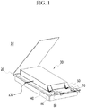
- FIG. 1 illustrates an exploded perspective view of the battery cell according to the present invention
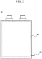
- FIG. 2 schematically illustrates a plane view of the battery cell.
- a battery cell 10 includes an electrode assembly 30, electrode tabs 40 and 50 extended from the electrode assembly 30, electrode leads 60 and 70 welded to the electrode tabs 40 and 50, and a battery case for accommodating the electrode assembly 30.
- the electrode tabs 40 and 50 are extended from each of the electrode plates of the electrode assembly 30, and the electrode leads 60 and 70 are electrically connected to a plurality of electrode tabs 40 and 50 extended from each electrode plate, respectively, for example, by welding, and are partially exposed to the outside of the battery case 20.
- an insulation film 80 is adhered on a portion of the upper and lower surfaces of the electrode leads 60 and 70 for increasing a sealing degree with the battery case 20, simultaneously with ensuring an electrical insulation state.
- the battery case 20 is composed of an aluminum laminate, provides a space for accommodating the electrode assembly 30, and has a pouch shape as a whole.
- the battery case 20 is sealed by thermal fusion, in which the electrode assembly 30 is accommodated therein with the electrolyte solution, and the electrode leads 60 and 70 outwardly protrude along with the outer circumference.
- the battery cell 10 includes the reference electrode 120 extended from one side end part to the outside of the electrode assembly 30, and the reference electrode 120 is partially drawn out to the outside through one side of the thermal fused outer circumference of the thermal fused battery case.
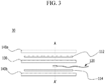
- FIG. 3 illustrates a schematic view of the electrode assembly of the present invention.
- the electrode assembly includes a positive electrode 112, a negative electrode 114, a reference electrode 120 of the same polarity as the negative electrode 114, a separator, and a pair of outer separators 140a and 140b.
- the electrode assembly 30 has a stacked structure, in which the reference electrode 120 is disposed between the separator and the negative electrode 114, the positive electrode 112 is disposed to face the negative electrode 114 and the reference electrode 120 with the separator 130 interposed therebetween, and on the surfaces of the positive electrode 112 and the negative electrode 114 which oppose the other surfaces of the positive electrode 112 and the negative electrode 114 facing each other, the outer separators 140a and 140b are disposed, respectively.
- the reference electrode 120 partially protrudes to the outside of the electrode assembly 30, with the components of the electrode assembly 30 being laminated, as shown in FIG. 1 , and the protruding part may be extended from the electrode assembly 30 to the outside of the battery cell 10, through the thermal fused portion, as shown in FIG. 2 .
- the reference electrode 120 is a reference electrode for measuring a relative potential for each of the positive electrode 112 and negative electrode 114 inside of the battery case 20, and since the reference electrode 120 is disposed between the positive electrode 112 and the negative electrode 114 where the actual electrochemical reaction occurs, the battery cell according to the present invention may allow precise measurement of the relative potential for each of the positive electrode 112 and the negative electrode 114.
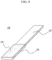
- the reference electrode 120 includes a main body 122 having a wire structure, in which the length is extended so that it may protrude from the inside of the electrode assembly 30 to the outside of the battery cell 10, and an electrode portion 124 having lithium titanium oxide (LTO) which is the negative electrode active material of the reference electrode 120, coated on a portion of the surface adjacent to one side end part of the main body 122, as the reference electrode active material.
- LTO lithium titanium oxide
- the reference electrode 120 further includes a separation film 126 configured to prevent electrical short circuit between the electrode portion 124 and the negative electrode 114, and allow lithium ion migration between the positive electrode 112 and the electrode portion 124.
- the main body 122 has an overall rectangular wire structure, as shown in FIG. 4, and FIG. 4 shows that the lithium titanium oxide is coated on only the upper surface of the main body 122 in the electrode portion 124, however, in some cases, the lithium titanium oxide may be coated on the lower surface of the main body 122, the front surface of the main body 122, or both the upper and lower surfaces of the main body 122, based on the reference part 124.
- the upper surface is a surface facing the positive electrode 112
- the lower surface is a surface opposing the upper surface
- an enamel resin which is an electrical insulating resin is coated on the remaining part except the electrode portion 124, and thus, the negative electrode 114 and the reference electrode 120 are not shortcircuited even in the state that the reference electrode 120 is closely adhered to the negative electrode 114.
- the separation film 126 has a cap shape in which only one side end part is opened so that the electrode portion 124 is wrapped, and thus, may completely wrap the electrode portion 124 with minimum volume and area.
- the contact resistance formed in the close adhesion interface of the separation film 126 and the negative electrode 114 may be minimized, and also the occurrence of gap between the negative electrode 114 and the separator may be minimized.
- the separation film 126 may also have a sticking agent or adhesive coated on the entire or portion of the inner surface thereof, in order to stably maintain the state of completely wrapping the surface of the electrode portion 124, and be composed of SRS separators (safety-reinforcing separators) having excellent adhesion and ductility.
- SRS separators safety-reinforcing separators
- FIG. 5 schematically illustrates a reference electrode 120a having a structure different from FIG. 4 .
- the reference electrode 120a includes a main body 122a having a wire structure, in which the length is extended so that it may protrude from the inside of the electrode assembly to the outside of the battery cell, and an electrode portion 124a having lithium titanium oxide (LTO) which is the negative electrode active material of the reference electrode 120a, coated on a portion of the surface adjacent to one side end part of the main body 122a, as the reference electrode active material.
- LTO lithium titanium oxide
- the reference electrode 120a further includes a separation film 126a configured to prevent electrical short circuit between the electrode portion 124a and the negative electrode 114, and allow lithium ion migration between the positive electrode 112 and the electrode portion 124a.
- the main body 122a has a cylindrical wire structure, differently from the main body 122 illustrated in FIG. 4 .
- the reference electrode active material is coated on the entire surface of the main body 122a, based on the electrode portion 124a, and the separation film 126a has a cylindrical cap shape, corresponding to the shape of the main body 122a.
- FIG. 6 illustrates a flow chart of the manufacturing method according to an exemplary embodiment of the present invention
- FIGS. 7 and 8 illustrate the reference cell of the present invention
- FIG. 9 illustrates a voltage change graph of the reference cell.
- the method of the present invention forms a reference cell 1 with a sample electrode 3 identical to the reference electrode 120 and a lithium electrode 2, and activates the sample electrode 3, in operation 210.
- the reference cell 1 is composed of a main body 4 accommodating an electrolyte solution, and a lithium electrode 2 mounted inside of the main body 4, and the sample electrode 3 is separably mounted inside of the main body 4.
- the sample electrode 3 works as the positive electrode of the reference cell 1
- the lithium electrode 2 works as the negative electrode.
- a microcurrent of about 0.00001 mAh to 0.003 mAh is applied to the sample electrode 3 and the lithium electrode 2 to charge the reference cell 1, which is discharged immediately thereafter.
- the microcurrent size is varied with the content of the electrode active material included in the sample electrode 3.
- the reference cell 1 after the reference cell 1 is completely charged, it is completely discharged, or repeatedly charged and discharged in the range of SOC 10% to SOC 90%, and when the voltage change of the reference cell 1 is measured during the course of charging and discharging as such, the results shown in FIG. 9 may be obtained.
- reference cell 1 is recharged to about 50% of the discharged capacity of the reference cell 1.
- the reference cell 1 reaches a plateau section where there is substantially no voltage change, and as a result, the sample electrode 3 is also subjected to formation of a plateau potential.
- an accurate electrode potential may be measured with a potential difference between the sample electrode 3 and the lithium electrode 2.
- the formation conditions including the microcurrent size, charge time, discharge time and formation time are confirmed and predetermined, and then operation 220 proceeds.
- the reference cell 1a is composed of a plurality of reference electrodes 120' and the lithium electrode 2 in operation 220, and each of the reference electrodes 120' is independently activated.
- the reference electrodes 120' are separably mounted inside of the main body 4, respectively.
- the reference electrodes 120' work as the positive electrode of the reference cell 1a, and the lithium electrode 2 works as the negative electrode.
- the microcurrent which was applied to the formation on the sample electrode 3 is applied to each of the reference electrodes 120' and the lithium electrode 2 to charge the reference cell 1a, which was discharged immediately thereafter.
- the reference cell 1a composed of the reference electrodes 120' may be subjected to formation with the charge time, discharge time and formation time which was predetermined in the activation process using the sample electrode 3.
- the reference cell 1a is charged and discharged, and then during the course of charging and discharging, the voltage change of the reference cell 1a is measured, the reference cell 1a is charged to about 50% of a discharged capacity, and when the reference cell 1a reaches a plateau section where there is substantially no voltage change of the reference cell 1a, the reference electrodes 120' is subjected to formation of a plateau potential. Further, the accurate electrode potential of the reference electrode 120' may be measured with a potential difference between the reference electrodes 120' and the lithium electrode 2.
- the electrode potential measured in the sample electrode 3 is substantially identical to the electrode potential of the reference electrodes 120'. Accordingly, only the process of formation on the reference electrodes 120' so that they have a plateau potential is carried out through operation 220, and a process of confirming a plateau section based on the voltage change of the reference cell 1a, and a process of measuring the electrode potential of each of the reference electrodes 120' may be omitted.
- Each of the reference electrodes 120' of which the activation was thus completed may be manufactured into the battery cell as shown in FIGS. 1 to 5 , with an electrode assembly, an electrolyte solution and a battery case in operation 230.
- FIGS. 10 and 11 illustrate graphs of resistance measurement of the battery cell according to the present invention.
- LiNi 0.6 Mn 0.2 Co 0.2 O 2 which is a lithium nickel cobalt manganese composite oxide
- Super-P conductive agent
- PVdF binder
- a negative electrode active material 96% by weight of a mixture of natural graphite and artificial graphite coated with amorphous carbon at a weight ratio of 95:5, 1% by weight of Super-P (conductive agent), 2% by weight of SBR (binder), 1% by weight of a thickener were added to H 2 O as a solvent, thereby preparing negative electrode mixture slurry, and coated on one surface of copper foil, and dried and pressed, thereby manufacturing a negative electrode.
- a reference electrode active material As a reference electrode active material, 80% by weight of lithium titanium oxide, 5% by weight of Super-P (conductive agent), and 15% by weight of KF9130 (binder) (13% Solution) were added to NMP as a solvent, thereby preparing negative electrode mixture slurry. Thereafter, the coating of one side end part was removed from the wire which is composed of copper, and of which the surface is coated with an enamel resin. Thereafter, the slurry was coated on the one side end part of the wire from which the coating was removed, dried and pressed, thereby manufacturing a reference electrode.
- a lithium battery cell was manufactured by using the positive electrode, the negative electrode and the reference electrode manufactured as described above and a carbonate electrolyte solution.
- the resistance of the negative electrode and the reference electrode was measured in the battery cell manufactured in Example 1, and is shown in FIG. 10 .
- the battery cell according to the present invention allows reliable electrode potential measurement, and almost no increase in internal resistance, by the structural characteristic of including the reference electrode inside.
- the method according to the present invention may significantly reduce time taken for the activation process, as compared with a method of combining each of reference electrodes with a battery cell, and then activating the reference electrodes.
- the method of the present invention allows more accurate measurement of the electrode potential of a reference electrode, since the potential of the reference electrode is measured by a lithium electrode of which the potential is already known, not a potential difference between the positive electrode of a battery cell and the reference electrode.
Description
- This application claims priority to and the benefit of Korean Patent Application No.
10-2005-0118607 - As the technology development and demand for mobile devices are increased, demand for rechargeable batteries as an energy source is rapidly growing, and accordingly, a lot of research on a rechargeable battery cell satisfying various needs is being conducted.
- Particularly, demand for a lithium rechargeable battery cell such as a lithium ion battery and a lithium ion polymer battery, having merits such as high energy density, discharge voltage and output stability is high.
- Meanwhile, an electrode potential of a battery is measured for developing a new battery cell, and confirming performance of the manufactured battery cell.
- For measuring an electrode potential, a method of measuring an electrode potential in a three-electrode system composed of a reference electrode, a working electrode, and a potential electrode is mainly used.
- The reference electrode is an electrode which is, for measuring the potential of an electrode forming a battery or an electrode where electrolysis occurs, used in manufacturing a battery circuit for electrode potential measurement in combination, and is used as a potential standard when measuring a relative value of an electrode potential.
- This reference electrode should satisfy the requirements such as following the Nernst equilibrium equation as a reversible electrode potential (an electrode in a reversible state), having a nonpolarizing characteristic to maintain a constant potential value at all time, having as little liquid potential difference as possible, having a small potential change even with a temperature change, and representing a constant potential value at a constant temperature.
- One reference electrode is combined per a battery cell, for measuring an electrode potential, and in order to increase reliability of the reference electrode, a process of activating the reference electrode to have a plateau potential having no change in the potential due to charging and discharging is carried out.
- This activation process is generally to apply a microcurrent to the reference electrode and a positive electrode of the battery cell to repeatedly charge and discharge the battery cell, while performing formation of a plateau section ('a plateau potential') where the reference electrode has a constant electrode potential.
- However, this activation process is to estimate the potential or plateau potential of the reference electrode with a potential difference between the positive electrode of a battery cell and the reference electrode, and the potential may be different from the actual potential of the reference electrode, or the potential of the activated reference electrode may not actually be the plateau potential.
- As such, in the case that the potential of the reference electrode is inaccurate, or the potential of the positive and negative electrodes of the battery cell is measured in the state of a non-plateau potential, the measured potential may be different from the actual potential of the positive and negative electrodes, and thus, the measurement method of the potential using the reference electrode is difficult to be reliable.
- Furthermore, a trace amount of lithium migrates from a positive electrode to a reference electrode in the course of activation, and then the electrode capacity of the positive electrode may be finely decreased by the lost lithium ions in the positive electrode.
- Besides, in the case that the battery cells are produced in large quantities, the activation process should be performed after one reference electrode is combined per one battery cell, and thus, the manufacturing process of the battery cells takes a long time.
US2011/250478 relates to a battery cell comprising an array of reference electrodes. - Accordingly, there is currently a high need for technique allowing the activation process of the reference electrode to be easily performed, and accurate measurement of the electrode potential of the reference electrode, and through this reference electrode, enabling highly reliable measurement of the electrode potential of the battery cell.
- The present invention has been made in an effort to provide a method of manufacturing a battery cell including a reference electrode for measuring a relative electrode potential, and a battery cell manufactured therefrom having advantages of solving the problems of the relevant art as described above, and overcoming the technical challenges which have been requested from the past.
- Specifically, the object of the present invention is, first, to reduce time taken for this process by simultaneously activating a plurality of reference electrodes, second, to perform formation on each of the plurality of reference electrodes so that they have an exact plateau potential, and lastly, to provide a method of manufacturing a battery cell, rendering the reference electrode to be directly involved in an electrochemical reaction of the positive and negative electrodes in the inside of the battery cell, thereby allowing highly reliable measurement of the electrode potential, and also having no performance degradation due to the reference electrode, and a battery cell manufactured therefrom.
- An exemplary embodiment of the present invention provides a method of manufacturing a battery cell including a reference electrode for measuring a relative electrode potential, including: (i) manufacturing a reference cell composed of an electrolyte solution, n reference electrodes (n≥2), and a lithium electrode; (ii) charging the reference cell by applying a microcurrent, and then discharging the reference cell immediately thereafter; (iii) charging the reference cell to 40% to 60% of a capacity discharged in the process (ii), thereby performing formation on the reference electrodes so that the reference electrodes have a plateau potential simultaneously; (iv) manufacturing n battery cells with each of the reference electrodes subjected to formation, an electrode assembly, the electrolyte solution and a battery case; and (v) measuring a relative potential of the reference electrode subjected to formation and a positive electrode, and a relative potential of the reference electrode and a negative electrode, in each of the battery cells.
- That is, by forming a reference cell with a plurality of reference electrodes and a lithium electrode, and then performing formation on the plurality of reference electrodes so that they have a plateau potential simultaneously, the method according to the present invention may significantly reduce time taken for the activation process, as compared with a method of combining each of reference electrodes with a battery cell, and then activating the reference electrodes.
- Besides, the method of the present invention measures a potential of the reference electrode, not by a potential difference between the positive electrode of a battery cell and the reference electrode, but by a lithium electrode of which the potential is already known, thereby allowing more accurate measurement of the electrode potential of the reference electrode.
- As such, the lithium electrode having a known potential may be a plate electrode composed of pure lithium, and the reference electrode subjected to formation may include lithium ions received from the lithium electrode in the processes (ii) and (iii).
- The lithium ions of the lithium electrode present in the reference electrode may be provided from the reference electrode to a positive electrode in the process (V), and positively involved in the capacity of the battery cell.
- The reference electrodes are all the electrodes having plateau potentials of 1.52 V to 1.54 V, and the plateau potential may be determined proportionally to an electrode active material content. Therefore, the reference electrodes may be subjected to formation of a plateau potential of 1.52 V to 1.54 V, specifically a plateau potential of 1.53 V.
- In the reference cell, each of the reference electrodes forms a positive electrode, the lithium electrode forms a negative electrode, and in the process (iii), the reference electrodes are independently subjected to formation, respectively. Herein 'being independently subjected to formation' refers to each of the reference electrodes being independently electrochemically reacted with the lithium electrode.
- The method of the present invention further includes (a) forming the reference cell with a sample electrode identical to the reference electrode and a lithium electrode, and then performing formation of the electrode potential of the sample electrode identically to the processes (ii) and (iii), thereby predetermining formation conditions including a microcurrent size, charge time, discharge time and/or formation time, wherein the processes (i) to (iii) are carried out, based on the formation conditions predetermined in the process (a).
- Since when the process (a) is thus carried out, the formation conditions for being applied to the reference electrodes may be predetermined, and thus, a plurality of reference electrodes may be subjected to formation more accurately and rapidly, in the activation process for the reference electrodes, that is, the processes (ii) and (iii).
- Meanwhile, since generally the reference electrode acts as resistance to the electrochemical reaction of the positive and negative electrodes of the battery cell, the electrode potential is measured in a state that the reference electrode is disposed on the exterior of the positive and negative electrodes. However, this measurement method does not match an actual electrode potential in the actual battery cell, since the reference electrode is positioned on the exterior of the electrodes, not between the positive electrode and the negative electrode where the actual electrochemical reaction occurs.
- Thus, the method of the present invention is configured to measure the relative potential of the positive and negative electrodes of the battery cell, while minimizing the resistance increase due to the reference resistance, by disposing the reference electrode at a position where the actual electrochemical reaction occurs.
- Specifically, in the method of the present invention, the process (iv) may include mounting the reference electrode between a separator and the negative electrode, with the reference electrode facing the negative electrode, laminating the positive electrode thereon with the separator interposed therebetween so that the positive electrode faces the negative electrode and the reference electrode, thereby forming an electrode assembly, and storing the electrode assembly and an electrolyte solution in a battery case, and then sealing the case, thereby manufacturing the battery cell.
- Accordingly, in the present invention, the reference electrode allows highly reliable measurement of an electrode potential by measuring the relative potential of each of the positive and negative electrodes at the position where the actual electrochemical reaction occurs.
- As a specific example, the reference electrode may include a main body having a wire structure composed of copper (Cu) or aluminum (Al); an electrode portion disposed on one side end part of the main body, and having an electrode active material coated on the surface; and a separation film preventing electrical short circuit between the electrode portion and the positive or negative electrode, and configured to allow lithium ions to migrate between the positive electrode and the electrode portion.
- That is, the reference electrode having a wire structure of small volume is disposed between the positive electrode and the negative electrode, thereby hardly affecting the volume of the battery cell, and also has a small area closely adhering to the negative electrode, thereby having low contact resistance.
- Generally, in the case that the reference electrode is disposed on the exterior of the positive and negative electrodes, there is a difference between a migration distance of lithium ions reversibly migrating between the positive electrode and the negative electrode, and a migration distance of lithium to the reference electrode, and thus, the electrode potential depending on the actual usage environment of the battery cell may not be measured precisely.
- Here, for disposing the reference electrode between the positive electrode and the negative electrode, two separators should be interposed between the positive electrode and the negative electrode, and the reference electrode should be interposed between the separators so that the short circuit due to contact between the electrodes is prevented, however, such structure is difficult to be realized due to the demerits as described below.
- First, since a pair of the separators interposed between the positive electrode and the negative electrode considerably restrict the migration of lithium ions, the battery cell as configured above has a low output characteristic.
- Second, on the interface where the separators come into contact with each other, high contact resistance is formed, and as a result, internal resistance of the battery cell is increased, so that the battery cell having desired performance may not be implemented.
- That is, in order to dispose the reference electrode between the positive electrode and the negative electrode where the actual electrochemical reaction occurs, the resistance increase due to the arrangement of the reference electrode in the inside of the battery cell should be overcome.
- Here, in the present invention, as described above, since the reference electrode has a wire structure having small volume and area, resistance due to the contact with the negative electrode may be greatly decreased.
- In addition, according to the findings of the inventors of the present invention, it was confirmed that the reference electrode having a structure in which a separation film having a small area wraps only the electrode portion formed on one side of the main body, even in the case of being disposed between the separator and the negative electrode, forms the resistance due to the contact between the separation film and the separator at a very low value, thereby not affecting the actual performance of the battery cell.
- In the reference electrode, the separation film may be formed in a cap shape wrapping the electrode portion. In this structure, the separation film may wrap the electrode portion with minimum volume and area, thereby further decreasing the contact resistance.
- Herein, the cap shape refers to a thimble shape in which one side end part of the main body and the both surfaces of the electrode portion adjacent to this end part are not exposed to the outside, wherein the separation film may be stuck or adhered on the surface of the electrode portion, in a state of wrapping the electrode portion.
- In the non-limiting example of the separation film, the separation film may be composed of a material selected from the group consisting of organic/inorganic composite porous SRS separators (safety-reinforcing separators), a polyolefin-based polymer, a polyester-based polymer, a polycarbonate-based polymer and glass fiber, and specifically, the SRS separators (safety-reinforcing separators) which do not generate heat shrinkage due to the thermal resistance of inorganic particles, and have excellent ductility, and high mechanical stiffness.
- Further, it is preferred that the separation film is thin so that the gap occurring between the separator and the negative electrode due to its thickness is minimized. However, in the case that the separation film is unduly thin, the mechanical stiffness of the separation film is weak, and thus, when the reference electrode flows by impact or vibration, the separation film may be torn by friction, thereby causing electrode short circuit, and accordingly, appropriate mechanical stiffness is required. Specifically, it is preferred that the separation film has a thickness equal to or less than half the separator thickness, more preferably has a thickness of 10% to 50% of the separator thickness.
- The reference electrode may be mounted on the electrode assembly so that the other side end part of the main body is extended to the outside of the battery case, with the electrode portion being interposed between the separator and the negative electrode.
- That is, the reference electrode has a wire structure of being extended from the inside to the outside of the battery cell, and the user may conveniently measure the relative potential by connecting a potential measuring apparatus to the reference electrode on the outside, and if required, may use the battery cell with the extended wire being cut.
- Herein, for the reference electrode, an electrically insulating film or resin may be coated on the remaining portion except the electrode portion in the main body so that the electrical insulation to the negative electrode may be ensured, and specifically an enamel resin may be used, but not limited thereto.
- Since the electrode active material has low reactivity to an electrolyte solution, it is not greatly limited as long as it is a stable material allowing slow degradation of the electrode and not interfering with reversibility of lithium ions, and specifically it may be lithium titanium oxide (LTO) having high structural stability and allowing slow electrode degradation.
- The electrode active material may be included in the reference electrode at 0.001% to 5% by weight, based on the total weight of the electrode active material of the negative electrode.
- It is not preferred that the content of the electrode active material is less than 0.001% based on the total weight of the electrode active material of the negative electrode, since the reference electrodes are not sufficiently coated, and thus, there is a risk of shorting, and it is also not preferred that the content is more than 5% by weight, since the reference electrode itself may act as resistance.
- The electrode portion may have a thickness of 0.1% to 20% relative to the thickness of the negative electrode. When the thickness of the electrode portion is less than 0.1% which is the minimum value of the range, the coating amount of the electrode active material is unduly small so that the electrode portion may not be utilized as the reference electrode for relative potential measurement, and when the thickness is more than 20% which is the maximum value of the range, an excessive gap between the separator and the negative electrode may be caused by the electrode portion, and thus, such thickness is not preferred.
- The present invention also provides a battery cell manufactured by the above method.
- The type of battery cell of the present invention is not particularly limited, however, as a specific example, it may be a lithium rechargeable battery such as a lithium ion (Li-ion) rechargeable battery, a lithium polymer (Li-polymer) rechargeable battery, or a lithium ion polymer (Li-ion polymer) rechargeable battery, having merits such as high energy density, discharge voltage and output stability.
- Generally, the lithium rechargeable battery is composed of a positive electrode, a negative electrode, a separator, and a lithium salt-containing non-aqueous electrolyte.
- The positive electrode is manufactured, for example, by coating a mixture of a positive active material, a conductive material and a binder on a positive electrode current collector and/or an extension current collecting part, and then drying it, and if necessary, a filler may be further added to the mixture.
- The positive electrode current collector and/or the extension current collecting part may be generally manufactured to have a thickness of 3 to 500 µm. These positive electrode current collector and extension current collecting part are not particularly limited as long as they do not cause chemical changes in the battery and have high conductivity, and for example, stainless steel, aluminum, nickel, titanium, sintered carbon, or aluminum or stainless steel of which the surface is treated with carbon, nickel, titanium, sliver and the like, may be used. The positive electrode current collector and the extension current collecting part may have higher adhesion strength to the positive active material by forming fine protrusions and depressions on the surface thereof, and may be formed in various shapes such as a film, a sheet, a foil, nets, a porous body, foam and a non-woven fabric body.
- The positive active material may include layered compounds or compounds substituted with one or more transition metals such as lithium cobalt oxide (LiCoO2) and lithium nickel oxide (LiNiO2); lithium manganese oxides of the chemical formulae of Li1+xMn2-xO4 (wherein x is 0 - 0.33), LiMnO3, LiMn2O3, LiMnO2 and the like; lithium copper oxide (Li2CuO2); vanadium oxides such as LiV3O8, LiFe3O4, V2O5 and Cu2V2O7; Ni-site type lithium nickel oxides represented by the chemical formula LiNi1-xMxO2 (wherein M = Co, Mn, Al, Cu, Fe, Mg, B or Ga, and x = 0.01 - 0.3); lithium manganese composite oxides represented by the chemical formula of LiMn2-xMxO2 (wherein M = Co, Ni, Fe, Cr, Zn or Ta, and x = 0.01 - 0.1) or Li2Mn3MO8 (wherein M = Fe, Co, Ni, Cu or Zn); LiMn2O4 in which some of Li of the chemical formula is substituted with an alkaline-earth metal ion; disulfide compounds; Fe2 (MoO4)3 and the like, but not limited thereto.
- The conductive material is added at 1 to 30% by weight, based on the total weight of the mixture including the positive active material. This conductive material is not particularly limited as long as it does not cause chemical changes in the battery, and has conductivity, and for example, graphite such as natural graphite or artificial graphite; carbon blacks such as carbon black, acetylene black, ketjen black, channel black, furnace black, lamp black and summer black; conductive fiber such as carbon fiber or metal fiber; metal powder such as carbon fluoride, aluminum and nickel powder; conductive whisky such as zinc oxide and potassium titanate; conductive metal oxides such as titanium oxide; conductive materials such as a polyphenylene derivative, and the like may be used.
- The binder is a component assisting in binding the active material and the conductive material and the like, and binding for the current collector, and generally added at 1 to 30% by weight, based on the total weight of the mixture including the positive active material. The example of this binder may include polyfluorovinylidene, polyvinylalcohol, carboxymethyl cellulose (CMC), starch, hydroxypropyl cellulose, regenerated cellulose, polyvinylpyrrolidone, tetrafluoroethylene, polyethylene, polypropylene, ethylene-propylene-diene terpolymer (EPDM), sulfonated EPDM, styrene butadiene rubber, fluorine rubber, various copolymers and the like.
- The filler is a component suppressing the expansion of the positive electrode, and optionally used, and is not particularly limited as long as it does not cause chemical changes in the battery and is a fibrous material, and for example, olefin-based polymers such as polyethylene and polypropylene; fibrous materials such as glass fiber and carbon fiber, may be used.
- The negative electrode is manufactured by coating the negative electrode active material on the negative electrode current collector and/or the extension current collecting part, and drying it, and if necessary, the components as described above may be optionally further included.
- The negative electrode current collector and/or the extension current collecting part is/are manufactured generally to have a thickness of 3 to 500 µm. This/These negative electrode current collector and/or extension current collecting part is/are not particularly limited as long as it/they does/do not cause chemical changes in the battery and has/have conductivity, and for example, copper, stainless steel, aluminum, nickel, titanium, sintered carbon, or copper or stainless steel of which the surface is treated with carbon, nickel, titanium, silver and the like, aluminum-cadmium alloy, or the like may be used.
- Further, like the positive electrode current collector, the binding force of the negative electrode active material may be strengthened by forming fine protrusions and depressions on the surface thereof, and various shapes such as a film, a sheet, a foil, nets, a porous body, foam and a non-woven fabric body may be used. The negative electrode active material may include, for example, carbon such as hard carbon, graphite-based carbon; metal composite oxides such as LixFe2O3 (0≤x≤1), LixWO2 (0≤x≤1) and SnxMe1-xMe'yOz (Me: Mn, Fe, Pb, Ge; Me': Al, B, P, Si,
groups - The separator is interposed between the positive electrode and the negative electrode, and an insulating thin film having high ion permeability and mechanical strength is used. The separator has a pore diameter of generally 0.01-10 µm, and a thickness of 5-300 µm. As this separator, in addition to the organic/inorganic composite porous SRS separators (safety-reinforcing separators) as described above; for example, olefin-based polymers such as chemical resistant and hydrophobic polypropylene; a sheet or non-woven fabric made of glass fiber or polyethylene, and the like are used. In the case that a solid electrolyte such as a polymer is used as the electrolyte, the solid electrolyte may also serve as the separator.
- The electrolyte solution may be a lithium salt-containing non-aqueous electrolyte solution, and is composed of a non-aqueous electrolyte solution and a lithium salt.
- The non-aqueous electrolyte solution may include a non-aqueous organic solvent, an organic solid electrolyte, an inorganic solid electrolyte and the like, but not limited thereto. The non-aqueous organic solvent may include, for example, aprotic organic solvents such as N-methyl-2-pyrrolidinone, propylene carbonate, ethylene carbonate, butylene carbonate, dimethyl carbonate, diethyl carbonate, γ-butyrolactone, 1,2-dimethoxy ethane, tetrahydroxy Franc, 2-methyl tetrahydrofuran, dimethylsulfoxide, 1,3-dioxolane, formamide, dimethylformamide, dioxolane, acetonitrile, nitromethane, methyl formate, methyl acetate, phosphate triester, trimethoxy methane, dioxolane derivative, sulfolane, methyl sulfolane, 1,3-dimethyl-2-imidazolidinone, propylene carbonate derivative, tetrahydrofuran derivative, ether, propionic acid methyl and ethyl propionate.
- The organic solid electrolyte may include, for example, polyethylene derivatives, polyethylene oxide derivatives, polypropylene oxide derivatives, phosphate ester polymers, poly agitation lysine, polyester sulfide, polyvinyl alcohol, polyfluorovinylidene, polymers including an ionic dissociation group, and the like.
- The inorganic solid electrolyte may include, for example, nitride, halides, sulfides or the like of Li such as Li3N, LiI, Li5Nl2, Li3N-LiI-LiOH, LiSiO4, LiSiO4-LiI-LiOH, Li2SiS3, Li4SiO4, Li4SiO4-LiI-LiOH and Li3PO4-Li2S-SiS2.
- The lithium salt is a material which is readily soluble in the non-aqueous electrolyte, and for example, LiCl, LiBr, LiI, LiClO4, LiBF4, LiB10Cl10, LiPF6, LiCF3SO3, LiCF3CO2, LiAsF6, LiSbF6, LiAlCl4, CH3SO3Li, CF3SO3Li, (CF3SO2)2NLi, chloroborane lithium, lower aliphatic carbonic acid lithium, 4 phenyl lithium borate, imide, and the like may be used.
- Further, to the non-aqueous electrolyte solution, for the purpose of improving charge and discharge characteristics, flame retardancy and the like, for example, pyridine, triethylphosphite, triethanolamine, cyclic ether, ethylene diamine, n-glyme, triamide hexaphosphate, nitrobenzene derivatives, sulfur, quinoneimine dyes, N-substituted oxazolidinone, N,N-substituted imidazolidine, ethylene glycol dialkyl ether, ammonium salts, pyrrole, 2-methoxy ethanol, aluminum trichloride, and the like may be added. In some cases, for imparting incombustibility, a halogen-containing solvent such as carbon tetrachloride and ethylene trifluoride may be further included, and for improving high temperature storage characteristics, carbon dioxide gas may be further included, and FEC (fluoro-ethylene carbonate), PRS (propene sultone) and the like may be further included.
- As a specific example, a lithium salt such as LiPF6, LiClO4, LiBF4 and LiN (SO2CF3)2 is added to a mixed solvent of a cyclic carbonate of EC or PC which is a high dielectric solvent, and a linear carbonate of DEC, DMC or EMC which is a low viscosity solvent, thereby preparing a lithium salt-containing non-aqueous electrolyte.
- The present invention also provides a battery pack and a device including one or more battery cells as the above.
-
-
FIG. 1 is an exploded perspective view of the battery cell according to the present invention; -
FIG. 2 is a plane schematic view of the battery cell ofFIG. 1 ; -
FIG. 3 is a schematic view of an electrode assembly; -
FIG. 4 is a schematic view of a reference electrode; -
FIG. 5 is a schematic view of another structure of the reference electrode; -
FIG. 6 is a flowchart of the manufacturing method according to the present invention; -
FIG. 7 is a schematic view of a reference cell including a sample electrode; -
FIG. 8 is a schematic view of a reference cell including the reference electrodes; -
FIG. 9 is a voltage change graph of the reference cell; -
FIG. 10 is a graph comparing the resistance between the negative electrode in the battery cell and the reference electrode according to Example 1 of the present invention; and -
FIG. 11 is another graph comparing the resistance between the negative electrode in the battery cell and the reference electrode according to Example 1 of the present invention. - Hereinafter, the present invention will be described, with reference to the drawings according to the exemplary embodiment of the present invention, however, this is for easier understanding of the present invention, and the scope of the present invention is not limited thereby.
-
FIG. 1 illustrates an exploded perspective view of the battery cell according to the present invention, andFIG. 2 schematically illustrates a plane view of the battery cell. - Referring to
FIG. 1 , abattery cell 10 includes anelectrode assembly 30,electrode tabs electrode assembly 30, electrode leads 60 and 70 welded to theelectrode tabs electrode assembly 30. - The
electrode tabs electrode assembly 30, and the electrode leads 60 and 70 are electrically connected to a plurality ofelectrode tabs battery case 20. In addition, aninsulation film 80 is adhered on a portion of the upper and lower surfaces of the electrode leads 60 and 70 for increasing a sealing degree with thebattery case 20, simultaneously with ensuring an electrical insulation state. - The
battery case 20 is composed of an aluminum laminate, provides a space for accommodating theelectrode assembly 30, and has a pouch shape as a whole. Thebattery case 20 is sealed by thermal fusion, in which theelectrode assembly 30 is accommodated therein with the electrolyte solution, and the electrode leads 60 and 70 outwardly protrude along with the outer circumference. - Here, the
battery cell 10 includes thereference electrode 120 extended from one side end part to the outside of theelectrode assembly 30, and thereference electrode 120 is partially drawn out to the outside through one side of the thermal fused outer circumference of the thermal fused battery case. -
FIG. 3 illustrates a schematic view of the electrode assembly of the present invention. Referring toFIG. 3 , the electrode assembly includes apositive electrode 112, anegative electrode 114, areference electrode 120 of the same polarity as thenegative electrode 114, a separator, and a pair ofouter separators - The
electrode assembly 30 has a stacked structure, in which thereference electrode 120 is disposed between the separator and thenegative electrode 114, thepositive electrode 112 is disposed to face thenegative electrode 114 and thereference electrode 120 with theseparator 130 interposed therebetween, and on the surfaces of thepositive electrode 112 and thenegative electrode 114 which oppose the other surfaces of thepositive electrode 112 and thenegative electrode 114 facing each other, theouter separators - Herein, the
reference electrode 120 partially protrudes to the outside of theelectrode assembly 30, with the components of theelectrode assembly 30 being laminated, as shown inFIG. 1 , and the protruding part may be extended from theelectrode assembly 30 to the outside of thebattery cell 10, through the thermal fused portion, as shown inFIG. 2 . - The
reference electrode 120 is a reference electrode for measuring a relative potential for each of thepositive electrode 112 andnegative electrode 114 inside of thebattery case 20, and since thereference electrode 120 is disposed between thepositive electrode 112 and thenegative electrode 114 where the actual electrochemical reaction occurs, the battery cell according to the present invention may allow precise measurement of the relative potential for each of thepositive electrode 112 and thenegative electrode 114. - The structure of the
reference electrode 120 is specifically illustrated inFIG. 4 . Referring toFIG. 4 , thereference electrode 120 includes amain body 122 having a wire structure, in which the length is extended so that it may protrude from the inside of theelectrode assembly 30 to the outside of thebattery cell 10, and anelectrode portion 124 having lithium titanium oxide (LTO) which is the negative electrode active material of thereference electrode 120, coated on a portion of the surface adjacent to one side end part of themain body 122, as the reference electrode active material. - The
reference electrode 120 further includes aseparation film 126 configured to prevent electrical short circuit between theelectrode portion 124 and thenegative electrode 114, and allow lithium ion migration between thepositive electrode 112 and theelectrode portion 124. - The
main body 122 has an overall rectangular wire structure, as shown inFIG. 4, and FIG. 4 shows that the lithium titanium oxide is coated on only the upper surface of themain body 122 in theelectrode portion 124, however, in some cases, the lithium titanium oxide may be coated on the lower surface of themain body 122, the front surface of themain body 122, or both the upper and lower surfaces of themain body 122, based on thereference part 124. - Here, the upper surface is a surface facing the
positive electrode 112, and the lower surface is a surface opposing the upper surface. - On the
main body 122, an enamel resin which is an electrical insulating resin is coated on the remaining part except theelectrode portion 124, and thus, thenegative electrode 114 and thereference electrode 120 are not shortcircuited even in the state that thereference electrode 120 is closely adhered to thenegative electrode 114. - The
separation film 126 has a cap shape in which only one side end part is opened so that theelectrode portion 124 is wrapped, and thus, may completely wrap theelectrode portion 124 with minimum volume and area. - Accordingly, even in the case that the
electrode portion 124 of thereference electrode 120 is closely adhered to thenegative electrode 114, the contact resistance formed in the close adhesion interface of theseparation film 126 and thenegative electrode 114 may be minimized, and also the occurrence of gap between thenegative electrode 114 and the separator may be minimized. - The
separation film 126 may also have a sticking agent or adhesive coated on the entire or portion of the inner surface thereof, in order to stably maintain the state of completely wrapping the surface of theelectrode portion 124, and be composed of SRS separators (safety-reinforcing separators) having excellent adhesion and ductility. -
FIG. 5 schematically illustrates areference electrode 120a having a structure different fromFIG. 4 . Referring toFIG. 5 , thereference electrode 120a includes amain body 122a having a wire structure, in which the length is extended so that it may protrude from the inside of the electrode assembly to the outside of the battery cell, and anelectrode portion 124a having lithium titanium oxide (LTO) which is the negative electrode active material of thereference electrode 120a, coated on a portion of the surface adjacent to one side end part of themain body 122a, as the reference electrode active material. - The
reference electrode 120a further includes aseparation film 126a configured to prevent electrical short circuit between theelectrode portion 124a and thenegative electrode 114, and allow lithium ion migration between thepositive electrode 112 and theelectrode portion 124a. - The
main body 122a has a cylindrical wire structure, differently from themain body 122 illustrated inFIG. 4 . - In this structure, the reference electrode active material is coated on the entire surface of the
main body 122a, based on theelectrode portion 124a, and theseparation film 126a has a cylindrical cap shape, corresponding to the shape of themain body 122a. - Meanwhile,
FIG. 6 illustrates a flow chart of the manufacturing method according to an exemplary embodiment of the present invention,FIGS. 7 and8 illustrate the reference cell of the present invention, andFIG. 9 illustrates a voltage change graph of the reference cell. - The method according to the present invention will be described in detail, based on the structures of the battery cell and the reference electrode as illustrated in
FIGS. 1 to 5 . - First, referring to
FIGS. 6 ,7 and9 together, the method of the present invention forms areference cell 1 with asample electrode 3 identical to thereference electrode 120 and alithium electrode 2, and activates thesample electrode 3, inoperation 210. - Herein, the
reference cell 1 is composed of amain body 4 accommodating an electrolyte solution, and alithium electrode 2 mounted inside of themain body 4, and thesample electrode 3 is separably mounted inside of themain body 4. Thesample electrode 3 works as the positive electrode of thereference cell 1, and thelithium electrode 2 works as the negative electrode. - Then, a microcurrent of about 0.00001 mAh to 0.003 mAh is applied to the
sample electrode 3 and thelithium electrode 2 to charge thereference cell 1, which is discharged immediately thereafter. Here, the microcurrent size is varied with the content of the electrode active material included in thesample electrode 3. - Here, after the
reference cell 1 is completely charged, it is completely discharged, or repeatedly charged and discharged in the range ofSOC 10% toSOC 90%, and when the voltage change of thereference cell 1 is measured during the course of charging and discharging as such, the results shown inFIG. 9 may be obtained. - Next,
reference cell 1 is recharged to about 50% of the discharged capacity of thereference cell 1. Here, thereference cell 1 reaches a plateau section where there is substantially no voltage change, and as a result, thesample electrode 3 is also subjected to formation of a plateau potential. Here, an accurate electrode potential may be measured with a potential difference between thesample electrode 3 and thelithium electrode 2. - As described above, in the activation process using the
sample electrode 3, the formation conditions including the microcurrent size, charge time, discharge time and formation time are confirmed and predetermined, and thenoperation 220 proceeds. - In this regard, referring to
FIGS. 6 ,8 and9 together, thereference cell 1a is composed of a plurality of reference electrodes 120' and thelithium electrode 2 inoperation 220, and each of the reference electrodes 120' is independently activated. - The reference electrodes 120' are separably mounted inside of the
main body 4, respectively. The reference electrodes 120' work as the positive electrode of thereference cell 1a, and thelithium electrode 2 works as the negative electrode. - Then, the microcurrent which was applied to the formation on the
sample electrode 3 is applied to each of the reference electrodes 120' and thelithium electrode 2 to charge thereference cell 1a, which was discharged immediately thereafter. - Here, the
reference cell 1a composed of the reference electrodes 120' may be subjected to formation with the charge time, discharge time and formation time which was predetermined in the activation process using thesample electrode 3. - That is, identically to the activation process of the
sample electrode 3, thereference cell 1a is charged and discharged, and then during the course of charging and discharging, the voltage change of thereference cell 1a is measured, thereference cell 1a is charged to about 50% of a discharged capacity, and when thereference cell 1a reaches a plateau section where there is substantially no voltage change of thereference cell 1a, the reference electrodes 120' is subjected to formation of a plateau potential. Further, the accurate electrode potential of the reference electrode 120' may be measured with a potential difference between the reference electrodes 120' and thelithium electrode 2. - In addition, since the
sample electrode 3 is identical to the reference electrode 120', the electrode potential measured in thesample electrode 3 is substantially identical to the electrode potential of the reference electrodes 120'. Accordingly, only the process of formation on the reference electrodes 120' so that they have a plateau potential is carried out throughoperation 220, and a process of confirming a plateau section based on the voltage change of thereference cell 1a, and a process of measuring the electrode potential of each of the reference electrodes 120' may be omitted. - Each of the reference electrodes 120' of which the activation was thus completed may be manufactured into the battery cell as shown in
FIGS. 1 to 5 , with an electrode assembly, an electrolyte solution and a battery case inoperation 230. - Meanwhile,
FIGS. 10 and11 illustrate graphs of resistance measurement of the battery cell according to the present invention. - Hereinafter, the experiments according to
FIGS. 10 and11 will be described in detail. - As a positive electrode active material, 90% by weight of LiNi0.6Mn0.2Co0.2O2 which is a lithium nickel cobalt manganese composite oxide, 5% by weight of Super-P (conductive agent), and 5% by weight of PVdF (binder) were added to NMP, thereby preparing positive electrode mixture slurry. This was coated on one surface of aluminum foil, and dried and pressed, thereby manufacturing a positive electrode.
- As a negative electrode active material, 96% by weight of a mixture of natural graphite and artificial graphite coated with amorphous carbon at a weight ratio of 95:5, 1% by weight of Super-P (conductive agent), 2% by weight of SBR (binder), 1% by weight of a thickener were added to H2O as a solvent, thereby preparing negative electrode mixture slurry, and coated on one surface of copper foil, and dried and pressed, thereby manufacturing a negative electrode.
- As a reference electrode active material, 80% by weight of lithium titanium oxide, 5% by weight of Super-P (conductive agent), and 15% by weight of KF9130 (binder) (13% Solution) were added to NMP as a solvent, thereby preparing negative electrode mixture slurry. Thereafter, the coating of one side end part was removed from the wire which is composed of copper, and of which the surface is coated with an enamel resin. Thereafter, the slurry was coated on the one side end part of the wire from which the coating was removed, dried and pressed, thereby manufacturing a reference electrode.
- A lithium battery cell was manufactured by using the positive electrode, the negative electrode and the reference electrode manufactured as described above and a carbonate electrolyte solution.
- The resistance of the negative electrode and the reference electrode was measured in the battery cell manufactured in Example 1, and is shown in
FIG. 10 . - According to
FIG. 10 , it is recognized that the negative electrode and the reference electrode have almost the same resistance value. - After formation on the lithium battery cell manufactured in Example 1 at 4.2 V, resistance changes due to discharge of the negative electrode and the reference electrode were measured in all areas of SOC, and the results are shown in the following Table 1, and
FIG. 11 .(Table 1) Negative electrode Reference electrode Rate of change (%) SOC95 2.22 2.25 1.11 SOC90 2.24 2.28 1.93 SOC85 2.25 2.31 2.66 SOC80 2.27 2.29 1.21 SOC75 2.29 2.33 1.89 SOC70 2.29 2.33 1.39 SOC65 2.28 2.29 0.66 SOC60 2.14 2.20 2.41 SOC55 2.13 2.14 0.47 SOC45 2.16 2.16 -0.05 SOC40 2.20 2.19 -0.54 SOC35 2.25 2.24 -0.50 SOC30 2.28 2.28 -0.15 SOC25 2.41 2.37 1.46 SOC20 2.54 2.53 0.18 SOC15 2.99 3.04 1.50 SOC10 4.38 4.40 0.49 SOC5 1035 9.69 -6.33 - According to Table 1 and
FIG. 11 , it is recognized that though in the battery cell according to the present invention, the reference electrode was disposed inside of the battery cell, specifically between the positive electrode and the negative electrode, there is substantially no difference in resistance from the negative electrode. - That is, the battery cell according to the present invention allows reliable electrode potential measurement, and almost no increase in internal resistance, by the structural characteristic of including the reference electrode inside.
- It is possible for a person with ordinary skill in the art to which the present invention pertains to perform various applications and modification within the scope of the present invention, based on the description above.
- As described above, by forming a reference cell with a plurality of reference electrodes and a lithium electrode, and then performing formation on the plurality of reference electrodes so that they have a plateau potential simultaneously, the method according to the present invention may significantly reduce time taken for the activation process, as compared with a method of combining each of reference electrodes with a battery cell, and then activating the reference electrodes.
- Besides, the method of the present invention allows more accurate measurement of the electrode potential of a reference electrode, since the potential of the reference electrode is measured by a lithium electrode of which the potential is already known, not a potential difference between the positive electrode of a battery cell and the reference electrode.
Claims (13)
- A method of manufacturing a battery cell including a reference electrode for measuring a relative electrode potential, the method comprising:(i) manufacturing a reference cell composed of an electrolyte solution, n reference electrodes (n≥2), and a lithium electrode;(ii) charging the reference cell by applying a microcurrent, and then discharging the reference cell immediately thereafter;(iii) charging the reference cell to 40% to 60% of a capacity discharged in the process (ii), thereby performing formation on the reference electrodes so that the reference electrodes have a plateau potential simultaneously;(iv) manufacturing n battery cells with each of the reference electrodes subjected to formation, an electrode assembly, an electrolyte solution and a battery case; and(v) measuring a relative potential of the reference electrode subjected to formation and a positive electrode, and a relative potential of the reference electrode and a negative electrode, in each of the battery cells.
- The method of claim 1, wherein the reference electrodes are all subjected to formation of a plateau potential of 1.52 V to 1.54 V.
- The method of claim 1, wherein the lithium electrode is a plate electrode composed of pure lithium.
- The method of claim 1, wherein the reference electrode subjected to formation includes lithium ions received from the lithium electrode in the processes (ii) and (iii).
- The method of claim 1, wherein in the reference cell, each of the reference electrodes forms the positive electrode, and the lithium electrode forms the negative electrode, and each of the reference electrodes is independently subjected to formation in the process (iii).
- The method of claim 1, further comprising:(a) forming the reference cell with a sample electrode identical to the reference electrode and the lithium electrode, and then performing formation of an electrode potential of the sample electrode identically to the processes (ii) and (iii), thereby predetermining formation conditions including a microcurrent size, charge time, discharge time and/or formation time,
wherein the processes (i) to (iii) are carried out, based on the formation conditions predetermined in the process (a). - The method of claim 1, wherein the reference electrode includes:a main body having a wire structure composed of copper (Cu) or aluminum (Al);an electrode portion disposed on one side end part of the main body, and having an electrode active material coated on a surface; anda separation film configured to prevent electric short circuit between the electrode portion and the positive or negative electrode, and allow migration of lithium ions between the positive electrode and the electrode portion.
- The method of claim 7, wherein the main body has an electrically insulating film or a resin coated on a remaining portion except the electrode portion.
- The method of claim 7, wherein the electrode active material is lithium titanium oxide (LTO).
- The method of claim 7, wherein the electrode active material is included in the reference electrode at 0.001% by weight to 5% by weight, based on a total weight of a negative electrode active material of the negative electrode.
- The method of claim 7, wherein the electrode portion has a thickness of 0.1% to 20%, relative to a thickness of the negative electrode.
- The method of claim 7, wherein the separation film has a cap shape wrapping the electrode portion.
- A battery cell manufactured by the method of any one of claims 1 to 12.
Applications Claiming Priority (2)
| Application Number | Priority Date | Filing Date | Title |
|---|---|---|---|
| KR1020150118607A KR101999773B1 (en) | 2015-08-24 | 2015-08-24 | Method of Producing Battery Cell Including Reference Electrode for Measuring Relative Electrode Potential and Battery Cell Produced by the Same |
| PCT/KR2016/009063 WO2017034210A1 (en) | 2015-08-24 | 2016-08-18 | Method for manufacturing battery cell including reference electrode for measurement of relative electrode potential and battery cell manufactured thereby |
Publications (3)
| Publication Number | Publication Date |
|---|---|
| EP3343688A4 EP3343688A4 (en) | 2018-07-04 |
| EP3343688A1 EP3343688A1 (en) | 2018-07-04 |
| EP3343688B1 true EP3343688B1 (en) | 2021-01-13 |
Family
ID=58100315
Family Applications (1)
| Application Number | Title | Priority Date | Filing Date |
|---|---|---|---|
| EP16839499.7A Active EP3343688B1 (en) | 2015-08-24 | 2016-08-18 | Method for manufacturing battery cell including reference electrode for measurement of relative electrode potential and battery cell manufactured thereby |
Country Status (6)
| Country | Link |
|---|---|
| US (1) | US10978683B2 (en) |
| EP (1) | EP3343688B1 (en) |
| JP (1) | JP6582117B2 (en) |
| KR (1) | KR101999773B1 (en) |
| CN (1) | CN108028431B (en) |
| WO (1) | WO2017034210A1 (en) |
Families Citing this family (13)
| Publication number | Priority date | Publication date | Assignee | Title |
|---|---|---|---|---|
| KR102003709B1 (en) * | 2016-08-23 | 2019-10-17 | 주식회사 엘지화학 | Test Cell Providing High-Reliable Test Result Regarding Test of Electrode Characteristic |
| CN108107092B (en) * | 2017-11-17 | 2019-09-27 | 清华大学 | A kind of infiltration preparation method of the lithium ion battery with reference electrode |
| EP4123780A1 (en) * | 2018-04-04 | 2023-01-25 | VARTA Microbattery GmbH | Secondary energy storage element with a reference electrode |
| KR102349300B1 (en) | 2018-04-10 | 2022-01-10 | 주식회사 엘지에너지솔루션 | Apparatus, method, battery pack and electrical system for determining electrode information of battery |
| CN110007245B (en) * | 2019-03-19 | 2021-08-06 | 合肥国轩高科动力能源有限公司 | Method for detecting N/P ratio design rationality of lithium ion battery by three electrodes |
| CN112430833B (en) * | 2019-08-26 | 2021-11-26 | 郑州深澜动力科技有限公司 | Metal lithium plating method used as reference electrode of three-electrode lithium ion battery |
| CN110797569B (en) * | 2019-10-31 | 2021-06-25 | 深圳新恒业电池科技有限公司 | Four-electrode lithium ion battery and potential measuring method thereof |
| CN113285133A (en) * | 2021-05-24 | 2021-08-20 | 中南大学 | In-situ test device and test method for potential distribution of lithium ion battery |
| CN113422115B (en) * | 2021-07-02 | 2023-08-25 | 广州小鹏汽车科技有限公司 | Lithium ion battery cell, lithium ion battery cell preparation method and lithium analysis detection method |
| CN116072813A (en) * | 2021-11-02 | 2023-05-05 | 宁德时代新能源科技股份有限公司 | Method for producing reference electrode, method for producing three-electrode cell, three-electrode cell |
| CN114824172B (en) * | 2022-05-13 | 2023-08-15 | 欣旺达电动汽车电池有限公司 | Reference electrode treatment method and three-electrode lithium ion battery |
| KR102543336B1 (en) * | 2022-11-30 | 2023-06-15 | (주)그린파워 | Series Battery Cell Formation Device |
| WO2024080812A1 (en) * | 2022-10-15 | 2024-04-18 | (주)그린파워 | Series battery cell formation device |
Family Cites Families (19)
| Publication number | Priority date | Publication date | Assignee | Title |
|---|---|---|---|---|
| KR100838164B1 (en) | 2004-12-16 | 2008-06-13 | 주식회사 엘지화학 | Reference Electrode Probe for 3 Electrode System And Method for Measurement of Electrode Potential of Secondary Battery Using The Same |
| PL2106625T3 (en) * | 2007-01-22 | 2012-07-31 | Commissariat Energie Atomique | Reference electrode, manufacturing method and battery comprising same |
| EP2206190A4 (en) | 2007-09-14 | 2012-07-11 | A123 Systems Inc | Lithium rechargeable cell with reference electrode for state of health monitoring |
| JP5446195B2 (en) | 2008-09-26 | 2014-03-19 | 日産自動車株式会社 | Lithium ion battery system and manufacturing method thereof |
| JP2011034952A (en) * | 2009-07-07 | 2011-02-17 | Toyota Motor Corp | Lithium ion secondary battery, vehicle, and battery-mounting apparatus |
| US8586222B2 (en) * | 2010-04-08 | 2013-11-19 | GM Global Technology Operations LLC | Lithium-ion cell with an array of reference electrodes |
| KR101453126B1 (en) * | 2010-07-20 | 2014-10-27 | 주식회사 엘지화학 | Method for fabricating pouch type lithium secondary battery and pouch type lithium secondary battery fabricated using the same |
| JP5594583B2 (en) * | 2010-07-30 | 2014-09-24 | 独立行政法人産業技術総合研究所 | Method for manufacturing reference electrode |
| US9698451B2 (en) | 2011-07-06 | 2017-07-04 | Apple Inc. | Using reference electrodes to manage batteries for portable electronic devices |
| KR101481860B1 (en) * | 2012-05-30 | 2015-01-14 | 주식회사 엘지화학 | Method for Preparation of Lithium Secondary Battery |
| KR101352559B1 (en) * | 2012-05-31 | 2014-01-17 | 이광현 | Apparatus for automatic processing and conveyance the marinefish |
| JP6068241B2 (en) * | 2013-04-15 | 2017-01-25 | 本田技研工業株式会社 | Method for manufacturing lithium ion battery |
| KR20140134516A (en) * | 2013-05-14 | 2014-11-24 | (주)에이치엔티 | Battery charge and discharge system utilizing C-rate and battery charge and discharge method thereby |
| US9379418B2 (en) * | 2013-06-20 | 2016-06-28 | Hrl Laboratories, Llc | Battery with reference electrode for voltage monitoring |
| KR101710655B1 (en) | 2013-07-04 | 2017-02-27 | 주식회사 엘지화학 | Battery cell having a reference electrode |
| WO2015040684A1 (en) * | 2013-09-18 | 2015-03-26 | 株式会社日立製作所 | Reference electrode with thermometer function, lithium-ion secondary battery including reference electrode with thermometer function, lithium-ion secondary battery system including reference electrode with thermometer function, and lithium-ion secondary battery control method |
| WO2015040685A1 (en) * | 2013-09-18 | 2015-03-26 | 株式会社日立製作所 | Lithium-ion secondary battery separator, lithium-ion secondary battery using lithium-ion secondary battery separator, and lithium-ion secondary battery module |
| WO2015049778A1 (en) * | 2013-10-04 | 2015-04-09 | 株式会社日立製作所 | Lithium ion secondary battery, lithium ion secondary battery system, method for detecting potential in lithium ion secondary battery, and method for controlling lithium ion secondary battery |
| WO2015127442A1 (en) * | 2014-02-24 | 2015-08-27 | Oned Material Llc | Anode, cell, and method of stabilizing an anode for use in a lithium ion electrochemical cell |
-
2015
- 2015-08-24 KR KR1020150118607A patent/KR101999773B1/en active IP Right Grant
-
2016
- 2016-08-18 JP JP2018500488A patent/JP6582117B2/en active Active
- 2016-08-18 US US15/743,797 patent/US10978683B2/en active Active
- 2016-08-18 EP EP16839499.7A patent/EP3343688B1/en active Active
- 2016-08-18 WO PCT/KR2016/009063 patent/WO2017034210A1/en active Application Filing
- 2016-08-18 CN CN201680043769.9A patent/CN108028431B/en active Active
Non-Patent Citations (1)
| Title |
|---|
| None * |
Also Published As
| Publication number | Publication date |
|---|---|
| EP3343688A4 (en) | 2018-07-04 |
| WO2017034210A1 (en) | 2017-03-02 |
| JP2018519647A (en) | 2018-07-19 |
| CN108028431A (en) | 2018-05-11 |
| US20180205049A1 (en) | 2018-07-19 |
| US10978683B2 (en) | 2021-04-13 |
| JP6582117B2 (en) | 2019-09-25 |
| EP3343688A1 (en) | 2018-07-04 |
| CN108028431B (en) | 2020-11-24 |
| KR101999773B1 (en) | 2019-07-12 |
| KR20170023455A (en) | 2017-03-06 |
Similar Documents
| Publication | Publication Date | Title |
|---|---|---|
| EP3343688B1 (en) | Method for manufacturing battery cell including reference electrode for measurement of relative electrode potential and battery cell manufactured thereby | |
| EP3035432B1 (en) | Battery cell bending apparatus comprising heating member | |
| EP3062379B1 (en) | Hybrid electrode assembly having stepped structure | |
| CN109073709B (en) | Method for estimating reaction of secondary battery and secondary battery including battery cell used for the same | |
| KR101830286B1 (en) | Battery Cell Preparation Method Pressurizing Electrode Assembly During Vitalization Process | |
| KR20170043761A (en) | Battery Cell Including Reference Electrode for Measuring Relative Electrode Potential | |
| EP3196970A1 (en) | Method for manufacturing lithium secondary battery and lithium secondary battery manufactured using same | |
| EP3605720B1 (en) | Battery cell including sealing tape for accelerating heat conduction | |
| KR20130117711A (en) | Lithium battery having higher performance | |
| US10868285B2 (en) | Pouch type battery cell including electrode lead of bending structure | |
| KR102145492B1 (en) | Battery System with Improved Rate Characteristic and Method for Generating Battery System | |
| EP3644428A1 (en) | Method for manufacturing lithium secondary battery and lithium secondary battery manufactured thereby | |
| KR101617420B1 (en) | Battery Pack Having Member for Measurement of Cell Voltage | |
| KR101763576B1 (en) | Electrode Assembly Enabling High Capacity with Small Volume and Secondary Battery Comprising the Same | |
| US20160211557A1 (en) | Method of manufacturing secondary battery and secondary battery using the same | |
| EP3370075A1 (en) | Test cell with high reliability in electrode property test | |
| KR101752864B1 (en) | Lithium Secondary Battery and Battery Module Comprising the Same | |
| US10468726B2 (en) | Negative electrode for preventing deposition of manganese and battery cell including the same | |
| KR20130117709A (en) | Lithium battery having higher performance | |
| KR101326082B1 (en) | Secondary Battery Having Electrode Tab of Excellent Productivity and Low Resistance | |
| KR20140006722A (en) | Method for preparing secondary battery, secondary battery prepared by the method and electrochemical cell containing the same | |
| KR102201632B1 (en) | Battery Cell Having Different Receiving Sizes between Upper Case and Lower Case | |
| KR101894126B1 (en) | Battery Cell Being Easy to Inject Electrolyte and Degas | |
| KR101631124B1 (en) | Secondary Battery Having Member for Temperature Measurement | |
| KR20200099744A (en) | Tray for activating battery cell to improve electrolyte wetting and the batter cell manufacturing method using thereof |
Legal Events
| Date | Code | Title | Description |
|---|---|---|---|
| STAA | Information on the status of an ep patent application or granted ep patent |
Free format text: STATUS: THE INTERNATIONAL PUBLICATION HAS BEEN MADE |
|
| PUAI | Public reference made under article 153(3) epc to a published international application that has entered the european phase |
Free format text: ORIGINAL CODE: 0009012 |
|
| STAA | Information on the status of an ep patent application or granted ep patent |
Free format text: STATUS: REQUEST FOR EXAMINATION WAS MADE |
|
| 17P | Request for examination filed |
Effective date: 20171228 |
|
| A4 | Supplementary search report drawn up and despatched |
Effective date: 20180606 |
|
| AK | Designated contracting states |
Kind code of ref document: A1 Designated state(s): AL AT BE BG CH CY CZ DE DK EE ES FI FR GB GR HR HU IE IS IT LI LT LU LV MC MK MT NL NO PL PT RO RS SE SI SK SM TR |
|
| AX | Request for extension of the european patent |
Extension state: BA ME |
|
| DAV | Request for validation of the european patent (deleted) | ||
| DAX | Request for extension of the european patent (deleted) | ||
| RIC1 | Information provided on ipc code assigned before grant |
Ipc: H01M 4/04 20060101ALI20200626BHEP Ipc: H01M 4/134 20100101ALI20200626BHEP Ipc: H01M 4/38 20060101ALI20200626BHEP Ipc: H01M 10/44 20060101ALI20200626BHEP Ipc: H01M 2/10 20060101ALI20200626BHEP Ipc: H01M 4/02 20060101ALN20200626BHEP Ipc: H01M 10/0525 20100101ALI20200626BHEP Ipc: H01M 10/058 20100101AFI20200626BHEP Ipc: H01M 2/16 20060101ALI20200626BHEP Ipc: H01M 4/485 20100101ALI20200626BHEP |
|
| GRAP | Despatch of communication of intention to grant a patent |
Free format text: ORIGINAL CODE: EPIDOSNIGR1 |
|
| STAA | Information on the status of an ep patent application or granted ep patent |
Free format text: STATUS: GRANT OF PATENT IS INTENDED |
|
| RIC1 | Information provided on ipc code assigned before grant |
Ipc: H01M 10/44 20060101ALI20200908BHEP Ipc: H01M 4/04 20060101ALI20200908BHEP Ipc: H01M 4/134 20100101ALI20200908BHEP Ipc: H01M 4/38 20060101ALI20200908BHEP Ipc: H01M 4/485 20100101ALI20200908BHEP Ipc: H01M 2/16 20060101ALI20200908BHEP Ipc: H01M 10/0525 20100101ALI20200908BHEP Ipc: H01M 10/058 20100101AFI20200908BHEP Ipc: H01M 2/10 20060101ALI20200908BHEP Ipc: H01M 4/02 20060101ALN20200908BHEP |
|
| INTG | Intention to grant announced |
Effective date: 20200928 |
|
| GRAS | Grant fee paid |
Free format text: ORIGINAL CODE: EPIDOSNIGR3 |
|
| GRAA | (expected) grant |
Free format text: ORIGINAL CODE: 0009210 |
|
| STAA | Information on the status of an ep patent application or granted ep patent |
Free format text: STATUS: THE PATENT HAS BEEN GRANTED |
|
| AK | Designated contracting states |
Kind code of ref document: B1 Designated state(s): AL AT BE BG CH CY CZ DE DK EE ES FI FR GB GR HR HU IE IS IT LI LT LU LV MC MK MT NL NO PL PT RO RS SE SI SK SM TR |
|
| REG | Reference to a national code |
Ref country code: GB Ref legal event code: FG4D |
|
| REG | Reference to a national code |
Ref country code: CH Ref legal event code: EP |
|
| REG | Reference to a national code |
Ref country code: IE Ref legal event code: FG4D |
|
| REG | Reference to a national code |
Ref country code: DE Ref legal event code: R096 Ref document number: 602016051491 Country of ref document: DE |
|
| REG | Reference to a national code |
Ref country code: AT Ref legal event code: REF Ref document number: 1355238 Country of ref document: AT Kind code of ref document: T Effective date: 20210215 |
|
| REG | Reference to a national code |
Ref country code: AT Ref legal event code: MK05 Ref document number: 1355238 Country of ref document: AT Kind code of ref document: T Effective date: 20210113 |
|
| REG | Reference to a national code |
Ref country code: NL Ref legal event code: MP Effective date: 20210113 |
|
| REG | Reference to a national code |
Ref country code: LT Ref legal event code: MG9D |
|
| PG25 | Lapsed in a contracting state [announced via postgrant information from national office to epo] |
Ref country code: NO Free format text: LAPSE BECAUSE OF FAILURE TO SUBMIT A TRANSLATION OF THE DESCRIPTION OR TO PAY THE FEE WITHIN THE PRESCRIBED TIME-LIMIT Effective date: 20210413 Ref country code: PT Free format text: LAPSE BECAUSE OF FAILURE TO SUBMIT A TRANSLATION OF THE DESCRIPTION OR TO PAY THE FEE WITHIN THE PRESCRIBED TIME-LIMIT Effective date: 20210513 Ref country code: GR Free format text: LAPSE BECAUSE OF FAILURE TO SUBMIT A TRANSLATION OF THE DESCRIPTION OR TO PAY THE FEE WITHIN THE PRESCRIBED TIME-LIMIT Effective date: 20210414 Ref country code: FI Free format text: LAPSE BECAUSE OF FAILURE TO SUBMIT A TRANSLATION OF THE DESCRIPTION OR TO PAY THE FEE WITHIN THE PRESCRIBED TIME-LIMIT Effective date: 20210113 Ref country code: HR Free format text: LAPSE BECAUSE OF FAILURE TO SUBMIT A TRANSLATION OF THE DESCRIPTION OR TO PAY THE FEE WITHIN THE PRESCRIBED TIME-LIMIT Effective date: 20210113 Ref country code: BG Free format text: LAPSE BECAUSE OF FAILURE TO SUBMIT A TRANSLATION OF THE DESCRIPTION OR TO PAY THE FEE WITHIN THE PRESCRIBED TIME-LIMIT Effective date: 20210413 Ref country code: LT Free format text: LAPSE BECAUSE OF FAILURE TO SUBMIT A TRANSLATION OF THE DESCRIPTION OR TO PAY THE FEE WITHIN THE PRESCRIBED TIME-LIMIT Effective date: 20210113 |
|
| PG25 | Lapsed in a contracting state [announced via postgrant information from national office to epo] |
Ref country code: RS Free format text: LAPSE BECAUSE OF FAILURE TO SUBMIT A TRANSLATION OF THE DESCRIPTION OR TO PAY THE FEE WITHIN THE PRESCRIBED TIME-LIMIT Effective date: 20210113 Ref country code: PL Free format text: LAPSE BECAUSE OF FAILURE TO SUBMIT A TRANSLATION OF THE DESCRIPTION OR TO PAY THE FEE WITHIN THE PRESCRIBED TIME-LIMIT Effective date: 20210113 Ref country code: LV Free format text: LAPSE BECAUSE OF FAILURE TO SUBMIT A TRANSLATION OF THE DESCRIPTION OR TO PAY THE FEE WITHIN THE PRESCRIBED TIME-LIMIT Effective date: 20210113 Ref country code: AT Free format text: LAPSE BECAUSE OF FAILURE TO SUBMIT A TRANSLATION OF THE DESCRIPTION OR TO PAY THE FEE WITHIN THE PRESCRIBED TIME-LIMIT Effective date: 20210113 Ref country code: SE Free format text: LAPSE BECAUSE OF FAILURE TO SUBMIT A TRANSLATION OF THE DESCRIPTION OR TO PAY THE FEE WITHIN THE PRESCRIBED TIME-LIMIT Effective date: 20210113 |
|
| PG25 | Lapsed in a contracting state [announced via postgrant information from national office to epo] |
Ref country code: IS Free format text: LAPSE BECAUSE OF FAILURE TO SUBMIT A TRANSLATION OF THE DESCRIPTION OR TO PAY THE FEE WITHIN THE PRESCRIBED TIME-LIMIT Effective date: 20210513 |
|
| REG | Reference to a national code |
Ref country code: DE Ref legal event code: R097 Ref document number: 602016051491 Country of ref document: DE |
|
| PG25 | Lapsed in a contracting state [announced via postgrant information from national office to epo] |
Ref country code: SM Free format text: LAPSE BECAUSE OF FAILURE TO SUBMIT A TRANSLATION OF THE DESCRIPTION OR TO PAY THE FEE WITHIN THE PRESCRIBED TIME-LIMIT Effective date: 20210113 Ref country code: EE Free format text: LAPSE BECAUSE OF FAILURE TO SUBMIT A TRANSLATION OF THE DESCRIPTION OR TO PAY THE FEE WITHIN THE PRESCRIBED TIME-LIMIT Effective date: 20210113 Ref country code: CZ Free format text: LAPSE BECAUSE OF FAILURE TO SUBMIT A TRANSLATION OF THE DESCRIPTION OR TO PAY THE FEE WITHIN THE PRESCRIBED TIME-LIMIT Effective date: 20210113 |
|
| PLBE | No opposition filed within time limit |
Free format text: ORIGINAL CODE: 0009261 |
|
| STAA | Information on the status of an ep patent application or granted ep patent |
Free format text: STATUS: NO OPPOSITION FILED WITHIN TIME LIMIT |
|
| PG25 | Lapsed in a contracting state [announced via postgrant information from national office to epo] |
Ref country code: DK Free format text: LAPSE BECAUSE OF FAILURE TO SUBMIT A TRANSLATION OF THE DESCRIPTION OR TO PAY THE FEE WITHIN THE PRESCRIBED TIME-LIMIT Effective date: 20210113 Ref country code: RO Free format text: LAPSE BECAUSE OF FAILURE TO SUBMIT A TRANSLATION OF THE DESCRIPTION OR TO PAY THE FEE WITHIN THE PRESCRIBED TIME-LIMIT Effective date: 20210113 Ref country code: SK Free format text: LAPSE BECAUSE OF FAILURE TO SUBMIT A TRANSLATION OF THE DESCRIPTION OR TO PAY THE FEE WITHIN THE PRESCRIBED TIME-LIMIT Effective date: 20210113 |
|
| 26N | No opposition filed |
Effective date: 20211014 |
|
| PG25 | Lapsed in a contracting state [announced via postgrant information from national office to epo] |
Ref country code: AL Free format text: LAPSE BECAUSE OF FAILURE TO SUBMIT A TRANSLATION OF THE DESCRIPTION OR TO PAY THE FEE WITHIN THE PRESCRIBED TIME-LIMIT Effective date: 20210113 Ref country code: ES Free format text: LAPSE BECAUSE OF FAILURE TO SUBMIT A TRANSLATION OF THE DESCRIPTION OR TO PAY THE FEE WITHIN THE PRESCRIBED TIME-LIMIT Effective date: 20210113 |
|
| PG25 | Lapsed in a contracting state [announced via postgrant information from national office to epo] |
Ref country code: SI Free format text: LAPSE BECAUSE OF FAILURE TO SUBMIT A TRANSLATION OF THE DESCRIPTION OR TO PAY THE FEE WITHIN THE PRESCRIBED TIME-LIMIT Effective date: 20210113 |
|
| REG | Reference to a national code |
Ref country code: CH Ref legal event code: PL |
|
| PG25 | Lapsed in a contracting state [announced via postgrant information from national office to epo] |
Ref country code: MC Free format text: LAPSE BECAUSE OF FAILURE TO SUBMIT A TRANSLATION OF THE DESCRIPTION OR TO PAY THE FEE WITHIN THE PRESCRIBED TIME-LIMIT Effective date: 20210113 |
|
| REG | Reference to a national code |
Ref country code: BE Ref legal event code: MM Effective date: 20210831 |
|
| PG25 | Lapsed in a contracting state [announced via postgrant information from national office to epo] |
Ref country code: LI Free format text: LAPSE BECAUSE OF NON-PAYMENT OF DUE FEES Effective date: 20210831 Ref country code: IT Free format text: LAPSE BECAUSE OF FAILURE TO SUBMIT A TRANSLATION OF THE DESCRIPTION OR TO PAY THE FEE WITHIN THE PRESCRIBED TIME-LIMIT Effective date: 20210113 Ref country code: CH Free format text: LAPSE BECAUSE OF NON-PAYMENT OF DUE FEES Effective date: 20210831 |
|
| PG25 | Lapsed in a contracting state [announced via postgrant information from national office to epo] |
Ref country code: IS Free format text: LAPSE BECAUSE OF FAILURE TO SUBMIT A TRANSLATION OF THE DESCRIPTION OR TO PAY THE FEE WITHIN THE PRESCRIBED TIME-LIMIT Effective date: 20210513 Ref country code: LU Free format text: LAPSE BECAUSE OF NON-PAYMENT OF DUE FEES Effective date: 20210818 |
|
| PG25 | Lapsed in a contracting state [announced via postgrant information from national office to epo] |
Ref country code: IE Free format text: LAPSE BECAUSE OF NON-PAYMENT OF DUE FEES Effective date: 20210818 Ref country code: BE Free format text: LAPSE BECAUSE OF NON-PAYMENT OF DUE FEES Effective date: 20210831 |
|
| REG | Reference to a national code |
Ref country code: DE Ref legal event code: R081 Ref document number: 602016051491 Country of ref document: DE Owner name: LG ENERGY SOLUTION, LTD., KR Free format text: FORMER OWNER: LG CHEM, LTD., SEOUL, KR |
|
| PG25 | Lapsed in a contracting state [announced via postgrant information from national office to epo] |
Ref country code: HU Free format text: LAPSE BECAUSE OF FAILURE TO SUBMIT A TRANSLATION OF THE DESCRIPTION OR TO PAY THE FEE WITHIN THE PRESCRIBED TIME-LIMIT; INVALID AB INITIO Effective date: 20160818 |
|
| P01 | Opt-out of the competence of the unified patent court (upc) registered |
Effective date: 20230323 |
|
| PG25 | Lapsed in a contracting state [announced via postgrant information from national office to epo] |
Ref country code: NL Free format text: LAPSE BECAUSE OF NON-PAYMENT OF DUE FEES Effective date: 20210113 Ref country code: CY Free format text: LAPSE BECAUSE OF FAILURE TO SUBMIT A TRANSLATION OF THE DESCRIPTION OR TO PAY THE FEE WITHIN THE PRESCRIBED TIME-LIMIT Effective date: 20210113 |
|
| REG | Reference to a national code |
Ref country code: GB Ref legal event code: 732E Free format text: REGISTERED BETWEEN 20230901 AND 20230906 |
|
| PGFP | Annual fee paid to national office [announced via postgrant information from national office to epo] |
Ref country code: GB Payment date: 20230720 Year of fee payment: 8 |
|
| PGFP | Annual fee paid to national office [announced via postgrant information from national office to epo] |
Ref country code: FR Payment date: 20230725 Year of fee payment: 8 Ref country code: DE Payment date: 20230720 Year of fee payment: 8 |