EP3343672B1 - Busbar for cooling battery cell and battery module using same - Google Patents
Busbar for cooling battery cell and battery module using same Download PDFInfo
- Publication number
- EP3343672B1 EP3343672B1 EP17750396.8A EP17750396A EP3343672B1 EP 3343672 B1 EP3343672 B1 EP 3343672B1 EP 17750396 A EP17750396 A EP 17750396A EP 3343672 B1 EP3343672 B1 EP 3343672B1
- Authority
- EP
- European Patent Office
- Prior art keywords
- busbar
- cooling plate
- thermal contact
- battery module
- battery cell
- Prior art date
- Legal status (The legal status is an assumption and is not a legal conclusion. Google has not performed a legal analysis and makes no representation as to the accuracy of the status listed.)
- Active
Links
Images




Classifications
-
- H—ELECTRICITY
- H01—ELECTRIC ELEMENTS
- H01M—PROCESSES OR MEANS, e.g. BATTERIES, FOR THE DIRECT CONVERSION OF CHEMICAL ENERGY INTO ELECTRICAL ENERGY
- H01M10/00—Secondary cells; Manufacture thereof
- H01M10/60—Heating or cooling; Temperature control
- H01M10/61—Types of temperature control
- H01M10/613—Cooling or keeping cold
-
- H—ELECTRICITY
- H01—ELECTRIC ELEMENTS
- H01M—PROCESSES OR MEANS, e.g. BATTERIES, FOR THE DIRECT CONVERSION OF CHEMICAL ENERGY INTO ELECTRICAL ENERGY
- H01M10/00—Secondary cells; Manufacture thereof
- H01M10/60—Heating or cooling; Temperature control
- H01M10/62—Heating or cooling; Temperature control specially adapted for specific applications
- H01M10/625—Vehicles
-
- H—ELECTRICITY
- H01—ELECTRIC ELEMENTS
- H01M—PROCESSES OR MEANS, e.g. BATTERIES, FOR THE DIRECT CONVERSION OF CHEMICAL ENERGY INTO ELECTRICAL ENERGY
- H01M10/00—Secondary cells; Manufacture thereof
- H01M10/60—Heating or cooling; Temperature control
- H01M10/65—Means for temperature control structurally associated with the cells
- H01M10/655—Solid structures for heat exchange or heat conduction
- H01M10/6553—Terminals or leads
-
- H—ELECTRICITY
- H01—ELECTRIC ELEMENTS
- H01M—PROCESSES OR MEANS, e.g. BATTERIES, FOR THE DIRECT CONVERSION OF CHEMICAL ENERGY INTO ELECTRICAL ENERGY
- H01M10/00—Secondary cells; Manufacture thereof
- H01M10/60—Heating or cooling; Temperature control
- H01M10/65—Means for temperature control structurally associated with the cells
- H01M10/655—Solid structures for heat exchange or heat conduction
- H01M10/6554—Rods or plates
-
- H—ELECTRICITY
- H01—ELECTRIC ELEMENTS
- H01M—PROCESSES OR MEANS, e.g. BATTERIES, FOR THE DIRECT CONVERSION OF CHEMICAL ENERGY INTO ELECTRICAL ENERGY
- H01M10/00—Secondary cells; Manufacture thereof
- H01M10/60—Heating or cooling; Temperature control
- H01M10/65—Means for temperature control structurally associated with the cells
- H01M10/658—Means for temperature control structurally associated with the cells by thermal insulation or shielding
-
- H—ELECTRICITY
- H01—ELECTRIC ELEMENTS
- H01M—PROCESSES OR MEANS, e.g. BATTERIES, FOR THE DIRECT CONVERSION OF CHEMICAL ENERGY INTO ELECTRICAL ENERGY
- H01M50/00—Constructional details or processes of manufacture of the non-active parts of electrochemical cells other than fuel cells, e.g. hybrid cells
- H01M50/50—Current conducting connections for cells or batteries
-
- H—ELECTRICITY
- H01—ELECTRIC ELEMENTS
- H01M—PROCESSES OR MEANS, e.g. BATTERIES, FOR THE DIRECT CONVERSION OF CHEMICAL ENERGY INTO ELECTRICAL ENERGY
- H01M50/00—Constructional details or processes of manufacture of the non-active parts of electrochemical cells other than fuel cells, e.g. hybrid cells
- H01M50/50—Current conducting connections for cells or batteries
- H01M50/502—Interconnectors for connecting terminals of adjacent batteries; Interconnectors for connecting cells outside a battery casing
- H01M50/503—Interconnectors for connecting terminals of adjacent batteries; Interconnectors for connecting cells outside a battery casing characterised by the shape of the interconnectors
-
- H—ELECTRICITY
- H01—ELECTRIC ELEMENTS
- H01M—PROCESSES OR MEANS, e.g. BATTERIES, FOR THE DIRECT CONVERSION OF CHEMICAL ENERGY INTO ELECTRICAL ENERGY
- H01M50/00—Constructional details or processes of manufacture of the non-active parts of electrochemical cells other than fuel cells, e.g. hybrid cells
- H01M50/50—Current conducting connections for cells or batteries
- H01M50/502—Interconnectors for connecting terminals of adjacent batteries; Interconnectors for connecting cells outside a battery casing
- H01M50/505—Interconnectors for connecting terminals of adjacent batteries; Interconnectors for connecting cells outside a battery casing comprising a single busbar
-
- Y—GENERAL TAGGING OF NEW TECHNOLOGICAL DEVELOPMENTS; GENERAL TAGGING OF CROSS-SECTIONAL TECHNOLOGIES SPANNING OVER SEVERAL SECTIONS OF THE IPC; TECHNICAL SUBJECTS COVERED BY FORMER USPC CROSS-REFERENCE ART COLLECTIONS [XRACs] AND DIGESTS
- Y02—TECHNOLOGIES OR APPLICATIONS FOR MITIGATION OR ADAPTATION AGAINST CLIMATE CHANGE
- Y02E—REDUCTION OF GREENHOUSE GAS [GHG] EMISSIONS, RELATED TO ENERGY GENERATION, TRANSMISSION OR DISTRIBUTION
- Y02E60/00—Enabling technologies; Technologies with a potential or indirect contribution to GHG emissions mitigation
- Y02E60/10—Energy storage using batteries
Definitions
- the present disclosure relates to a busbar for cooling battery cells and a battery module using the same, and more particularly, to a busbar for cooling battery cells, which efficiently cools an electrode lead portion of a battery cell emitting a large amount of heat and allows simplification and size reduction of a structure of a battery module, and a battery module using the same.
- secondary batteries refer to chargeable-dischargeable batteries such as lithium ion batteries, lithium polymer batteries, nickel cadmium batteries, nickel metal hydride batteries, nickel zinc batteries, and the like.
- thermoelectrical based thermal management of electric devices US 2015/372356 , US2014/370339 and JP2009 245730 disclose thermoelectrical based thermal management of electric devices.
- the present disclosure is designed to solve the problems of the related art, and therefore the present disclosure is directed to providing a busbar for cooling battery cells, which efficiently cools an electrode lead portion of a battery cell emitting a large amount of heat and allows simplification and size reduction of a structure of a battery module and reduction in manufacturing costs of the battery module, and a battery module using the busbar.
- a busbar for cooling battery cells as found in the subject matter of the set of claims, which is configured to cool a plurality of battery cells included in a battery module, the busbar comprising: a body portion formed in a strap shape and contacting an electrode lead of each battery cell; and a bent portion integrally formed with the body portion and extending from one end of the body portion to be bent in a thickness direction of the body portion, wherein the bent portion comprises: a coupling groove coupled to a coupling protrusion that is prepared on a cooling plate of the battery module or a coupling protrusion that is prepared on a predetermined frame of the battery module, the predetermined frame supporting the busbar; and a thermal contact surface thermally contacting the cooling plate.
- the busbar further comprises an insulating member at least on the thermal contact surface of the bent portion, the insulating member being configured to prevent current flow between the busbar and the cooling plate.
- the busbar further comprises a gap filler at least on the thermal contact surface of the bent portion, the gap filler being configured to prevent separation between the bent portion and the cooling plate and to transfer heat therebetween.
- a battery module comprising: a busbar configured to connect an electrode lead of one battery cell to an electrode lead of another battery cell; a cooling plate having a first thermal contact portion, which thermally contacts a body of each battery cell or a cooling pin configured to transfer heat of each battery cell, and a second thermal contact portion, which thermally contacts one end of the busbar, the cooling plate being configured to transfer heat generated from each battery cell to a heat sink; an insulating member interposed between the one end of the busbar and the second thermal contact portion of the cooling plate and configured to prevent current flow between the busbar and the cooling plate; and a gap filler interposed between the one end of the busbar and the second thermal contact portion of the cooling plate and configured to prevent separation between the busbar and the cooling plate and to transfer heat therebetween.
- the busbar comprises; a body portion formed in a strap shape and contacting the electrode lead of the battery cell; and a bent portion integrally formed with the body portion and extending from one end of the body portion to be bent in a thickness direction of the body portion, wherein the bent portion may comprise: a coupling groove coupled to a coupling protrusion that is prepared on the cooling plate or on a predetermined frame of the battery module, the predetermined frame being configured to support the busbar; and a thermal contact surface thermally contacting the second thermal contact portion.
- the busbar may further comprise a protruding portion integrally formed with the body portion to extend from the body portion and electrically connected to a terminal of a control circuit configured to control the battery module.
- the insulating member may be interposed at least between the thermal contact surface of the bent portion and the second thermal contact portion of the cooling plate.
- the busbar which electrically connects electrode leads of the battery cells to each other, thermally contacts the cooling plate and thus cools the battery cells, whereby the electrode leads of the battery cells, which emit a relatively large amount of heat, may be efficiently cooled, and cooling pins used for cooling the battery cells in the battery module may be omitted to allow simplification and size reduction of a structure of the battery module and reduction in manufacturing costs of the battery module.
- the bent portion prepared in the busbar is coupled to the protrusion prepared on the cooling plate or the like and thus thermally contacts the cooling plate, and the gap filler is arranged between the bent portion and the cooling plate, whereby the possibility of separation between the busbar and the cooling plate due to vibrations generated in vehicle environments, external impacts, assembly errors, or the like may be structurally fundamentally prevented, and the cooling capability and durability of the battery module may be improved.
- the cooling plate thermally contacts the electrode leads of the battery cells as well as the bodies of the battery cells and thus transfers total heat of the battery cells to the heat sink, whereby the cooling capability or cooling efficiency of the battery module may be further improved.
- FIGS. 1 and 2 respectively show a perspective view and a front view illustrating a battery module according to an embodiment of the present disclosure.
- FIG. 3 shows a perspective view illustrating that a cooling plate of the battery module of FIG. 1 is disassembled.
- a battery module 100 may include a battery cell stack structure 110, a cooling plate 120, and a control circuit panel 130.
- the battery cell stack structure 110 may include a plurality of battery cells 140 and a plurality of busbars 150 corresponding thereto, and may further include a busbar frame 160 or the like.
- the battery cell stack structure 110 has a stack structure in which the plurality of battery cells 140 are sequentially stacked. In this case, each battery cell 140 may be configured in a pouch type to be easily stacked.
- the battery cell 140 may be a pouch type battery cell obtained by placing an electrode assembly in a pouch case (laminate sheet) including a metal layer and a resin layer, followed by sealing a rim of the case by thermal fusion.
- a cooling pin (not shown) may be interposed between the battery cells, the cooling pin contacting an outer body of the battery cell, that is, the pouch case of the battery cell.
- the cooling pin may be formed in a plate shape and contact a body of the battery cell, and a lower end of the cooling pin may contact the cooling plate 120, whereby the cooling pin may transfer heat generated from the battery cell to the cooling plate 120.
- the battery cell stack structure 110 may be configured without the cooling pin. The reason is that battery modules according to various embodiments of the present disclosure may basically cool the battery cell via the busbar 150.
- the busbar 150 of the battery cell stack structure 110 contacts an electrode lead 142 of the battery cell 140, thereby electrically connecting the electrode lead of one battery cell to the electrode lead of another battery cell, and simultaneously, thermally contacts the cooling plate 120 via one end of the busbar, thereby transferring heat generated from electrode leads of the battery cells to the cooling plate 120.
- the cooling plate 120 thermally contacts a heat sink (not shown) configured to absorb heat by using a refrigerant, and transfers heat generated from the battery cells to the heat sink.
- a heat sink (not shown) configured to absorb heat by using a refrigerant, and transfers heat generated from the battery cells to the heat sink.
- the refrigerant such as cooling water, cooling gas, or air, which moves through the flow path, absorbs heat transferred through the cooling plate 120 and discharges the heat outside the heat sink.
- the cooling plate 120 may be arranged under the battery cell stack structure 110, and may include a first thermal contact portion 122 and a second thermal contact portion 124.
- the first thermal contact portion 122 is configured in a plate shape on the whole and arranged parallel to a stacking direction of the battery cell stack structure 110, thermally contacts the body of the battery cell 140 or the cooling pin, which transfers the heat of the battery cell 140, via an upper surface of the first thermal contact portion 122, and thermally contacts the heat sink via a lower surface of the first thermal contact portion 122.
- the second thermal contact portion 124 vertically protrudes from the upper surface of the first thermal contact portion 122 and thermally contacts the one end of the busbar 150. In this case, as shown in FIGS.
- the second thermal contact portion 124 may be configured as a plurality of protruding portions respectively thermally contacting busbars of the battery cell stack structure 110, and of course, may also be configured as a single protruding portion of a wall shape, which thermally contacts all of the busbars.
- control circuit panel 130 includes a control circuit configured to control operations of the battery module 100.
- the control circuit may control charge-discharge operations of the plurality of battery cells 140 included in the battery module 100, or may perform energy balancing or the like to prevent a voltage imbalance between the battery cells and to maintain a voltage balance between the battery cells.
- Terminals 132 of the control circuit are respectively electrically connected to corresponding busbars 150.
- FIG. 4 shows an enlarged view illustrating a portion A of FIG. 1 .
- the busbar 150 of the battery cell stack structure 110 is basically a member configured to connect the plurality of battery cells 140 included in the battery module 100 in series or parallel. That is, the busbar 150 contacts the electrode lead 142 of each battery cell 140 and electrically connects the electrode lead of one battery cell to the electrode lead of another battery cell. Further, according to the present disclosure, the busbar 150 thermally contacts the second thermal contact portion 124 of the cooling plate 120 via the one end thereof, and transfers the heat generated from the electrode lead of each battery cell to the cooling plate 120.
- the battery module 100 may include an insulating member 170 and a gap filler 180.
- the insulating member 170 is interposed between the one end of the busbar 150 and the second thermal contact portion 124 of the cooling plate 120 and prevents current flow between the busbar 150 and the cooling plate 120.
- the insulating member 170 may include various materials having insulating properties, such as silicone, butyl rubber, polyvinyl chloride, polyethylene terephthalate, or polyimide.
- the insulating member 170 may be realized in the form of an insulating tape.
- the gap filler 180 is interposed between the one end of the busbar 150 and the second thermal contact portion 124 of the cooling plate 120, and transfers heat between the busbar 150 and the cooling plate 120 while preventing separation therebetween.
- the gap filler 180 may include an elastic and thermally conductive material such as an elastomer.
- the gap filler 180 may include an elastic rubber, an adhesive material, or the like.
- FIGS. 5 and 6 respectively show a perspective view and a side view illustrating a busbar for cooling battery cells according to an embodiment of the present disclosure.
- the busbar 150 for cooling battery cells may include a body portion 152 and a bent portion 154, and may further include a protruding portion 158.
- the body portion 152 is formed in a strap shape and contacts the electrode lead 142 of the battery cell 140. In this case, the body portion 152 may contact and be coupled to the electrode lead 142 by welding or the like.
- the bent portion 154 is integrally formed with the body portion 152 and extends from one end of the body portion 152 to be bent in a thickness direction of the body portion 152.
- the busbar 150 includes the bent portion 154 in the one end thereof, the bent portion 154 being bent in the thickness direction of the body portion 152, whereby the busbar 150 may have an expanded area of a thermal contact surface thermally contacting the cooling plate 120 while having a coupling groove 156 coupled to a coupling protrusion that is prepared on the cooling plate 120 or a coupling protrusion that is prepared on a predetermined frame 160 of the battery module 100, the predetermined frame 160 being configured to support the busbar 150.
- the protruding portion 158 is integrally formed with the body portion 152 to protrude from the body portion 152, and is electrically connected to a terminal 132 of the control circuit configured to control the battery module 100.
- the insulating member 170 or the gap filler 180 of the battery module 100 may be arranged on the bent portion 154 of the busbar 150. That is, the insulating member 170 or the gap filler 180 of the battery module 100, as shown in FIG. 4 , may be realized as a separate member interposed between the thermal contact surface (lower surface) of the bent portion 154 formed in the busbar 150 and the second thermal contact portion 124 of the cooling plate 120, and of course, may also be realized in the form of a coating material or covering material coated on or attached to a surface of the bent portion 154 of the busbar 150.
- FIG. 7 shows a vertical cross-sectional view illustrating a portion B of FIG. 5 .
- the busbar 150 for cooling battery cells may further include an insulating member 172 and a gap filler 182.
- the insulating member 172 at least on the thermal contact surface of the bent portion 154, prevents current flow between the busbar 150 and the cooling plate 120.
- the insulating member 172 may be realized in the form of an insulation covering material coated on the surface of the bent portion 154.
- the gap filler 180 at least on the thermal contact surface of the bent portion 154, prevents separation between the bent portion 154 and the cooling plate 120 and transfers heat therebetween.
- the gap filler 180 may be realized in the form of an elastic polymer member attached onto the thermal contact surface of the bent portion 154.
- busbar 150 may be coupled to a coupling protrusion that is prepared on a busbar frame 160, which supports the busbar 150, or a coupling protrusion that is prepared on the cooling plate 120, via the coupling groove 156 of the bent portion 154 of the busbar 150.
- FIG. 8 shows a perspective view illustrating the busbar frame 160 of the battery module 100 of FIG. 1 .
- the busbar frame 160 of the battery module 100 may include a plurality of slots 162, a support portion 164, and a coupling protrusion 166.
- the busbar frame 160 supports the busbar 150, thereby bringing the body portion 152 of the busbar 150 into contact with the electrode lead 142 of the battery cell 140 and bringing the bent portion 154 of the busbar 150 into thermal contact with the second thermal contact portion 124 of the cooling plate 120. That is, the electrode lead 142 of the battery cell 140 is arranged to be inserted into a slot 162 of the busbar frame 160.
- the busbar 150 is arranged to be supported by the support portion 164 of the busbar frame 160, and contacts and is coupled to the electrode lead 142 of the battery cell 140, which is inserted into the corresponding slot 162.
- the bent portion 154 of the busbar 150 may be coupled to the coupling protrusion 166 of the busbar frame 160 via the coupling groove 156 of the bent portion 154.
- the thermal contact surface (lower surface) of the bent portion 154 coupled to the coupling protrusion 166 of the busbar frame 160 thermally contacts the second thermal contact portion 124 of the cooling plate 120.
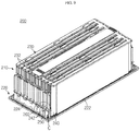
- FIG. 9 shows a perspective view illustrating a battery module 200 according to another embodiment of the present disclosure.
- FIG. 10 shows a perspective view illustrating that a cooling plate 220 of the battery module 200 of FIG. 9 is disassembled.
- the battery module 200 may include a battery cell stack structure 210, the cooling plate 220, and a control circuit panel 230.
- the battery cell stack structure 210 may include a plurality of battery cells 240 and a plurality of busbars 250 corresponding thereto, and may further include a busbar frame 260 or the like. Configurations and operations of the battery cell stack structure 210, the cooling plate 220, and the control circuit panel 230 may be basically described identically to those of the battery cell stack structure 110, the cooling plate 120, and the control circuit panel 130 shown in FIGS. 1 to 3 .
- a coupling protrusion coupled to a busbar 250 of the battery cell stack structure 210 is formed on a second thermal contact portion 224 of the cooling plate 220 rather than on the busbar frame 260. That is, the second thermal contact portion 224 of the cooling plate 220 includes a correspondence coupling groove 226 and a coupling protrusion 228, which coincide with a bent portion of the busbar 250 in terms of shape.
- FIG. 11 shows an enlarged view illustrating a portion C of FIG. 9 .
- the busbar 250 of the battery cell stack structure 210 contacts an electrode lead 242 of each battery cell 240 and electrically connects the electrode lead of one battery cell to the electrode lead of another battery cell.
- the busbar 250 thermally contacts the second thermal contact portion 224 of the cooling plate 220 via the bent portion thereof, and transfers heat generated from electrode leads of the battery cells to the cooling plate 220.
- the bent portion of the busbar 250 is inserted into the correspondence coupling groove 226 formed in the second thermal contact portion 224 of the cooling plate 220, and is coupled to the coupling protrusion 228 of the second thermal contact portion 224.
- an insulating member and a gap filler of the battery module 200 may be arranged on an inner surface of the bent portion of the busbar 250 and an inner surface of the correspondence coupling groove 226 of the cooling plate 120.
- the busbar 150 of the battery module 200 may include an insulating layer and an elastic polymer layer on a thermal contact surface of the bent portion formed in the busbar 250, as shown in FIG. 7 .
- Each of battery modules according to various embodiments of the present disclosure may be included in various vehicles using electric power, such as electric vehicles or hybrid electric vehicles, and may be realized as a power supply configured to supply power in a corresponding vehicle environment.
- the battery cells are cooled by bringing the busbar, which electrically connects the electrode leads of the battery cells to each other, into thermal contact with the cooling plate, whereby the electrode leads of the battery cells, which emit a relatively large amount of heat, may be efficiently cooled, and the cooling pins used for cooling the battery cells in the battery module may be omitted to allow simplification and size reduction of a structure of the battery module and reduction in manufacturing costs of the battery module.
- the bending portion prepared in the busbar is coupled to the protrusion prepared on the cooling plate or the like and thus thermally contacts the cooling plate, and the gap filler is arranged between the bent portion and the cooling plate, whereby the possibility of separation between the busbar and the cooling plate due to vibrations generated in vehicle environments, external impacts, assembly errors, or the like may be structurally fundamentally prevented, and the cooling capability and durability of the battery module may be improved.
- the cooling plate thermally contacts the electrode leads of the battery cells as well as the bodies of the battery cells and thus transfers total heat of the battery cells to the heat sink, whereby the cooling capability or cooling efficiency of the battery module may be further improved.
Landscapes
- Chemical & Material Sciences (AREA)
- Chemical Kinetics & Catalysis (AREA)
- Electrochemistry (AREA)
- General Chemical & Material Sciences (AREA)
- Engineering & Computer Science (AREA)
- Manufacturing & Machinery (AREA)
- Battery Mounting, Suspending (AREA)
- Secondary Cells (AREA)
- Connection Of Batteries Or Terminals (AREA)
Description
- The present disclosure relates to a busbar for cooling battery cells and a battery module using the same, and more particularly, to a busbar for cooling battery cells, which efficiently cools an electrode lead portion of a battery cell emitting a large amount of heat and allows simplification and size reduction of a structure of a battery module, and a battery module using the same.
- Generally, secondary batteries refer to chargeable-dischargeable batteries such as lithium ion batteries, lithium polymer batteries, nickel cadmium batteries, nickel metal hydride batteries, nickel zinc batteries, and the like.
- Recently, as secondary batteries are applied to devices requiring high output voltages and large charge capacities, such as electric vehicles or hybrid electric vehicles, stack-structured battery modules, in which unit battery cells having an output voltage ranging from about 2.5 V to about 4.2 V are connected in series or parallel and stacked, are widely being used. Thus, there is a trend of a rapid increase in interests and requests regarding techniques that allow efficient cooling of a battery module and simplification and size reduction of a structure of the battery module.
- However, as disclosed in Korean Patent Publication No.
10-2013-0021794 - In addition, as disclosed in Korean Patent No.
10-1415050 -
US 2015/372356 ,US2014/370339 andJP2009 245730 - The present disclosure is designed to solve the problems of the related art, and therefore the present disclosure is directed to providing a busbar for cooling battery cells, which efficiently cools an electrode lead portion of a battery cell emitting a large amount of heat and allows simplification and size reduction of a structure of a battery module and reduction in manufacturing costs of the battery module, and a battery module using the busbar.
- In one aspect of the present disclosure, there is provided a busbar for cooling battery cells as found in the subject matter of the set of claims, which is configured to cool a plurality of battery cells included in a battery module, the busbar comprising: a body portion formed in a strap shape and contacting an electrode lead of each battery cell; and a bent portion integrally formed with the body portion and extending from one end of the body portion to be bent in a thickness direction of the body portion, wherein the bent portion comprises: a coupling groove coupled to a coupling protrusion that is prepared on a cooling plate of the battery module or a coupling protrusion that is prepared on a predetermined frame of the battery module, the predetermined frame supporting the busbar; and a thermal contact surface thermally contacting the cooling plate.
- In one embodiment, the busbar further comprises an insulating member at least on the thermal contact surface of the bent portion, the insulating member being configured to prevent current flow between the busbar and the cooling plate.
- In one embodiment, the busbar further comprises a gap filler at least on the thermal contact surface of the bent portion, the gap filler being configured to prevent separation between the bent portion and the cooling plate and to transfer heat therebetween.
- In another aspect of the present disclosure as found in the subject matter of the set of claims, there is also provided a battery module comprising: a busbar configured to connect an electrode lead of one battery cell to an electrode lead of another battery cell; a cooling plate having a first thermal contact portion, which thermally contacts a body of each battery cell or a cooling pin configured to transfer heat of each battery cell, and a second thermal contact portion, which thermally contacts one end of the busbar, the cooling plate being configured to transfer heat generated from each battery cell to a heat sink; an insulating member interposed between the one end of the busbar and the second thermal contact portion of the cooling plate and configured to prevent current flow between the busbar and the cooling plate; and a gap filler interposed between the one end of the busbar and the second thermal contact portion of the cooling plate and configured to prevent separation between the busbar and the cooling plate and to transfer heat therebetween.
- The busbar comprises; a body portion formed in a strap shape and contacting the electrode lead of the battery cell; and a bent portion integrally formed with the body portion and extending from one end of the body portion to be bent in a thickness direction of the body portion, wherein the bent portion may comprise: a coupling groove coupled to a coupling protrusion that is prepared on the cooling plate or on a predetermined frame of the battery module, the predetermined frame being configured to support the busbar; and a thermal contact surface thermally contacting the second thermal contact portion.
- In one embodiment, the busbar may further comprise a protruding portion integrally formed with the body portion to extend from the body portion and electrically connected to a terminal of a control circuit configured to control the battery module.
- In one embodiment, the insulating member may be interposed at least between the thermal contact surface of the bent portion and the second thermal contact portion of the cooling plate.
- According to the present disclosure, the busbar, which electrically connects electrode leads of the battery cells to each other, thermally contacts the cooling plate and thus cools the battery cells, whereby the electrode leads of the battery cells, which emit a relatively large amount of heat, may be efficiently cooled, and cooling pins used for cooling the battery cells in the battery module may be omitted to allow simplification and size reduction of a structure of the battery module and reduction in manufacturing costs of the battery module.
- In addition, the bent portion prepared in the busbar is coupled to the protrusion prepared on the cooling plate or the like and thus thermally contacts the cooling plate, and the gap filler is arranged between the bent portion and the cooling plate, whereby the possibility of separation between the busbar and the cooling plate due to vibrations generated in vehicle environments, external impacts, assembly errors, or the like may be structurally fundamentally prevented, and the cooling capability and durability of the battery module may be improved.
- Further, the cooling plate thermally contacts the electrode leads of the battery cells as well as the bodies of the battery cells and thus transfers total heat of the battery cells to the heat sink, whereby the cooling capability or cooling efficiency of the battery module may be further improved.
- Furthermore, it will be obviously understood by one of ordinary skill in the art from the following detailed description that various technical problems not mentioned above may be solved according to various embodiments of the present disclosure.
-
-
FIG. 1 is a perspective view illustrating a battery module according to an embodiment of the present disclosure. -
FIG. 2 is a front view illustrating the battery module ofFIG. 1 . -
FIG. 3 is a perspective view illustrating that a cooling plate of the battery module ofFIG. 1 is disassembled. -
FIG. 4 is an enlarged view illustrating a portion A ofFIG. 1 . -
FIG. 5 is a perspective view illustrating a busbar for cooling battery cells according to an embodiment of the present disclosure. -
FIG. 6 is a side view illustrating the busbar ofFIG. 5 . -
FIG. 7 is a vertical cross-sectional view illustrating a portion B ofFIG. 5 . -
FIG. 8 is a perspective view illustrating a busbar frame of the battery module ofFIG. 1 . -
FIG. 9 is a perspective view illustrating a battery module according to another embodiment of the present disclosure. -
FIG. 10 is a perspective view illustrating that a cooling plate of the battery module ofFIG. 9 is disassembled. -
FIG. 11 is an enlarged view illustrating a portion C ofFIG. 9 . - Hereinafter, embodiments of the present disclosure will be described in detail with reference to the accompanying drawings to clarify aspects of the present disclosure. However, descriptions of the related art, which may obscure the aspects of the present disclosure, will be omitted. In addition, it should be understood that terms used herein are defined by taking into account functions in the present disclosure and may vary depending upon intentions of designers or manufacturers, customs, or the like. Therefore, it will be understood that the terms used herein should be defined based on the disclosure throughout the specification.
-
FIGS. 1 and2 respectively show a perspective view and a front view illustrating a battery module according to an embodiment of the present disclosure. In addition,FIG. 3 shows a perspective view illustrating that a cooling plate of the battery module ofFIG. 1 is disassembled. - As shown in
FIGS. 1 to 3 , abattery module 100 according to an embodiment of the present disclosure may include a batterycell stack structure 110, acooling plate 120, and acontrol circuit panel 130. Here, the batterycell stack structure 110 may include a plurality ofbattery cells 140 and a plurality ofbusbars 150 corresponding thereto, and may further include abusbar frame 160 or the like. The batterycell stack structure 110 has a stack structure in which the plurality ofbattery cells 140 are sequentially stacked. In this case, eachbattery cell 140 may be configured in a pouch type to be easily stacked. That is, thebattery cell 140 may be a pouch type battery cell obtained by placing an electrode assembly in a pouch case (laminate sheet) including a metal layer and a resin layer, followed by sealing a rim of the case by thermal fusion. In addition, a cooling pin (not shown) may be interposed between the battery cells, the cooling pin contacting an outer body of the battery cell, that is, the pouch case of the battery cell. The cooling pin may be formed in a plate shape and contact a body of the battery cell, and a lower end of the cooling pin may contact thecooling plate 120, whereby the cooling pin may transfer heat generated from the battery cell to thecooling plate 120. In one embodiment, the batterycell stack structure 110 may be configured without the cooling pin. The reason is that battery modules according to various embodiments of the present disclosure may basically cool the battery cell via thebusbar 150. - Although described again below, the
busbar 150 of the batterycell stack structure 110 contacts anelectrode lead 142 of thebattery cell 140, thereby electrically connecting the electrode lead of one battery cell to the electrode lead of another battery cell, and simultaneously, thermally contacts thecooling plate 120 via one end of the busbar, thereby transferring heat generated from electrode leads of the battery cells to thecooling plate 120. - The
cooling plate 120 thermally contacts a heat sink (not shown) configured to absorb heat by using a refrigerant, and transfers heat generated from the battery cells to the heat sink. Generally, a flow path is formed inside the heat sink, and the refrigerant, such as cooling water, cooling gas, or air, which moves through the flow path, absorbs heat transferred through thecooling plate 120 and discharges the heat outside the heat sink. For this purpose, thecooling plate 120 may be arranged under the batterycell stack structure 110, and may include a firstthermal contact portion 122 and a secondthermal contact portion 124. In this case, the firstthermal contact portion 122 is configured in a plate shape on the whole and arranged parallel to a stacking direction of the batterycell stack structure 110, thermally contacts the body of thebattery cell 140 or the cooling pin, which transfers the heat of thebattery cell 140, via an upper surface of the firstthermal contact portion 122, and thermally contacts the heat sink via a lower surface of the firstthermal contact portion 122. The secondthermal contact portion 124 vertically protrudes from the upper surface of the firstthermal contact portion 122 and thermally contacts the one end of thebusbar 150. In this case, as shown inFIGS. 1 to 3 , the secondthermal contact portion 124 may be configured as a plurality of protruding portions respectively thermally contacting busbars of the batterycell stack structure 110, and of course, may also be configured as a single protruding portion of a wall shape, which thermally contacts all of the busbars. - In addition, the
control circuit panel 130 includes a control circuit configured to control operations of thebattery module 100. The control circuit may control charge-discharge operations of the plurality ofbattery cells 140 included in thebattery module 100, or may perform energy balancing or the like to prevent a voltage imbalance between the battery cells and to maintain a voltage balance between the battery cells.Terminals 132 of the control circuit are respectively electrically connected tocorresponding busbars 150. -
FIG. 4 shows an enlarged view illustrating a portion A ofFIG. 1 . - As shown in
FIG. 4 , thebusbar 150 of the batterycell stack structure 110 is basically a member configured to connect the plurality ofbattery cells 140 included in thebattery module 100 in series or parallel. That is, thebusbar 150 contacts theelectrode lead 142 of eachbattery cell 140 and electrically connects the electrode lead of one battery cell to the electrode lead of another battery cell. Further, according to the present disclosure, thebusbar 150 thermally contacts the secondthermal contact portion 124 of thecooling plate 120 via the one end thereof, and transfers the heat generated from the electrode lead of each battery cell to thecooling plate 120. For this purpose, thebattery module 100 may include an insulatingmember 170 and agap filler 180. - In this case, the insulating
member 170 is interposed between the one end of thebusbar 150 and the secondthermal contact portion 124 of thecooling plate 120 and prevents current flow between thebusbar 150 and thecooling plate 120. The insulatingmember 170 may include various materials having insulating properties, such as silicone, butyl rubber, polyvinyl chloride, polyethylene terephthalate, or polyimide. In addition, the insulatingmember 170 may be realized in the form of an insulating tape. - In addition, the
gap filler 180 is interposed between the one end of thebusbar 150 and the secondthermal contact portion 124 of thecooling plate 120, and transfers heat between thebusbar 150 and thecooling plate 120 while preventing separation therebetween. Thegap filler 180 may include an elastic and thermally conductive material such as an elastomer. In addition, thegap filler 180 may include an elastic rubber, an adhesive material, or the like. -
FIGS. 5 and6 respectively show a perspective view and a side view illustrating a busbar for cooling battery cells according to an embodiment of the present disclosure. - As shown in
FIGS. 5 and6 , thebusbar 150 for cooling battery cells according to an embodiment of the present disclosure may include abody portion 152 and abent portion 154, and may further include a protrudingportion 158. Thebody portion 152 is formed in a strap shape and contacts theelectrode lead 142 of thebattery cell 140. In this case, thebody portion 152 may contact and be coupled to theelectrode lead 142 by welding or the like. Thebent portion 154 is integrally formed with thebody portion 152 and extends from one end of thebody portion 152 to be bent in a thickness direction of thebody portion 152. As such, thebusbar 150 includes thebent portion 154 in the one end thereof, thebent portion 154 being bent in the thickness direction of thebody portion 152, whereby thebusbar 150 may have an expanded area of a thermal contact surface thermally contacting thecooling plate 120 while having acoupling groove 156 coupled to a coupling protrusion that is prepared on thecooling plate 120 or a coupling protrusion that is prepared on apredetermined frame 160 of thebattery module 100, thepredetermined frame 160 being configured to support thebusbar 150. The protrudingportion 158 is integrally formed with thebody portion 152 to protrude from thebody portion 152, and is electrically connected to aterminal 132 of the control circuit configured to control thebattery module 100. - In addition, the insulating
member 170 or thegap filler 180 of thebattery module 100 may be arranged on thebent portion 154 of thebusbar 150. That is, the insulatingmember 170 or thegap filler 180 of thebattery module 100, as shown inFIG. 4 , may be realized as a separate member interposed between the thermal contact surface (lower surface) of thebent portion 154 formed in thebusbar 150 and the secondthermal contact portion 124 of thecooling plate 120, and of course, may also be realized in the form of a coating material or covering material coated on or attached to a surface of thebent portion 154 of thebusbar 150. -
FIG. 7 shows a vertical cross-sectional view illustrating a portion B ofFIG. 5 . - As shown in
FIG. 7 , thebusbar 150 for cooling battery cells according to an embodiment of the present disclosure may further include an insulatingmember 172 and agap filler 182. In this case, the insulatingmember 172, at least on the thermal contact surface of thebent portion 154, prevents current flow between thebusbar 150 and thecooling plate 120. For example, the insulatingmember 172 may be realized in the form of an insulation covering material coated on the surface of thebent portion 154. In addition, thegap filler 180, at least on the thermal contact surface of thebent portion 154, prevents separation between thebent portion 154 and thecooling plate 120 and transfers heat therebetween. For example, thegap filler 180 may be realized in the form of an elastic polymer member attached onto the thermal contact surface of thebent portion 154. - In addition, the
busbar 150 may be coupled to a coupling protrusion that is prepared on abusbar frame 160, which supports thebusbar 150, or a coupling protrusion that is prepared on thecooling plate 120, via thecoupling groove 156 of thebent portion 154 of thebusbar 150. -
FIG. 8 shows a perspective view illustrating thebusbar frame 160 of thebattery module 100 ofFIG. 1 . - As shown in
FIG. 8 , thebusbar frame 160 of thebattery module 100 according to an embodiment of the present disclosure may include a plurality ofslots 162, asupport portion 164, and acoupling protrusion 166. Thebusbar frame 160 supports thebusbar 150, thereby bringing thebody portion 152 of thebusbar 150 into contact with theelectrode lead 142 of thebattery cell 140 and bringing thebent portion 154 of thebusbar 150 into thermal contact with the secondthermal contact portion 124 of thecooling plate 120. That is, theelectrode lead 142 of thebattery cell 140 is arranged to be inserted into aslot 162 of thebusbar frame 160. In addition, thebusbar 150 is arranged to be supported by thesupport portion 164 of thebusbar frame 160, and contacts and is coupled to theelectrode lead 142 of thebattery cell 140, which is inserted into thecorresponding slot 162. Here, thebent portion 154 of thebusbar 150 may be coupled to thecoupling protrusion 166 of thebusbar frame 160 via thecoupling groove 156 of thebent portion 154. The thermal contact surface (lower surface) of thebent portion 154 coupled to thecoupling protrusion 166 of thebusbar frame 160 thermally contacts the secondthermal contact portion 124 of thecooling plate 120. -
FIG. 9 shows a perspective view illustrating abattery module 200 according to another embodiment of the present disclosure.FIG. 10 shows a perspective view illustrating that acooling plate 220 of thebattery module 200 ofFIG. 9 is disassembled. - As shown in
FIGS. 9 and10 , thebattery module 200 according to another embodiment of the present disclosure may include a batterycell stack structure 210, thecooling plate 220, and acontrol circuit panel 230. Here, the batterycell stack structure 210 may include a plurality ofbattery cells 240 and a plurality ofbusbars 250 corresponding thereto, and may further include abusbar frame 260 or the like. Configurations and operations of the batterycell stack structure 210, thecooling plate 220, and thecontrol circuit panel 230 may be basically described identically to those of the batterycell stack structure 110, thecooling plate 120, and thecontrol circuit panel 130 shown inFIGS. 1 to 3 . - It should be noted that a coupling protrusion coupled to a
busbar 250 of the batterycell stack structure 210 is formed on a secondthermal contact portion 224 of thecooling plate 220 rather than on thebusbar frame 260. That is, the secondthermal contact portion 224 of thecooling plate 220 includes acorrespondence coupling groove 226 and acoupling protrusion 228, which coincide with a bent portion of thebusbar 250 in terms of shape. -
FIG. 11 shows an enlarged view illustrating a portion C ofFIG. 9 . - As shown in
FIG. 11 , thebusbar 250 of the batterycell stack structure 210 contacts anelectrode lead 242 of eachbattery cell 240 and electrically connects the electrode lead of one battery cell to the electrode lead of another battery cell. In addition, thebusbar 250 thermally contacts the secondthermal contact portion 224 of thecooling plate 220 via the bent portion thereof, and transfers heat generated from electrode leads of the battery cells to thecooling plate 220. In this case, the bent portion of thebusbar 250 is inserted into thecorrespondence coupling groove 226 formed in the secondthermal contact portion 224 of thecooling plate 220, and is coupled to thecoupling protrusion 228 of the secondthermal contact portion 224. In this case, an insulating member and a gap filler of thebattery module 200 may be arranged on an inner surface of the bent portion of thebusbar 250 and an inner surface of thecorrespondence coupling groove 226 of thecooling plate 120. For example, thebusbar 150 of thebattery module 200 may include an insulating layer and an elastic polymer layer on a thermal contact surface of the bent portion formed in thebusbar 250, as shown inFIG. 7 . - Each of battery modules according to various embodiments of the present disclosure may be included in various vehicles using electric power, such as electric vehicles or hybrid electric vehicles, and may be realized as a power supply configured to supply power in a corresponding vehicle environment.
- As described above, according to the present disclosure, the battery cells are cooled by bringing the busbar, which electrically connects the electrode leads of the battery cells to each other, into thermal contact with the cooling plate, whereby the electrode leads of the battery cells, which emit a relatively large amount of heat, may be efficiently cooled, and the cooling pins used for cooling the battery cells in the battery module may be omitted to allow simplification and size reduction of a structure of the battery module and reduction in manufacturing costs of the battery module. In addition, the bending portion prepared in the busbar is coupled to the protrusion prepared on the cooling plate or the like and thus thermally contacts the cooling plate, and the gap filler is arranged between the bent portion and the cooling plate, whereby the possibility of separation between the busbar and the cooling plate due to vibrations generated in vehicle environments, external impacts, assembly errors, or the like may be structurally fundamentally prevented, and the cooling capability and durability of the battery module may be improved. Further, the cooling plate thermally contacts the electrode leads of the battery cells as well as the bodies of the battery cells and thus transfers total heat of the battery cells to the heat sink, whereby the cooling capability or cooling efficiency of the battery module may be further improved. Furthermore, it will be understood that, in the art and in the related art, various technical problems other than those mentioned herein may be solved according to the embodiments of the present disclosure.
- Heretofore, the present disclosure has been described with reference to some specific embodiments. However, it will be clearly understood by those skilled in the art that various modified embodiments may be made without departing from the scope of the present disclosure. Therefore, the foregoing embodiments should be considered in a descriptive perspective rather than in a limited perspective. That is, it should be understood that the scope of the present disclosure is defined by the appended claims.
Claims (7)
- A battery module (100, 200) comprising a plurality of battery cells (140, 240), the battery module comprising:a busbar (150, 250) configured to connect an electrode lead of one battery cell to an electrode lead (142, 242) of another battery cell;a cooling plate (120, 220) having a first thermal contact portion (122), which thermally contacts a body of each battery cell or a cooling pin configured to transfer heat of each battery cell, and a second thermal contact portion (124, 224), which thermally contacts one end of the busbar, the cooling plate being configured to transfer heat generated from each battery cell to a heat sink;an insulating member interposed (170, 172) between the one end of the busbar and the second thermal contact portion of the cooling plate and configured to prevent current flow between the busbar and the cooling plate; anda gap filler (180, 182) interposed between the one end of the busbar and the second thermal contact portion of the cooling plate and configured to prevent separation between the busbar and the cooling plate and to transfer heat therebetween;said busbar comprising a body portion (152) formed in a strap shape and contacting the electrode lead of each battery cell; a bent portion (154) integrally formed with the body portion and extending from one end of the body portion to be bent in a thickness direction of the body portion, and the bent portion comprises: a coupling groove (156, 226) coupled to a coupling protrusion (166, 228) that is prepared on the cooling plate or a coupling protrusion that is prepared on a predetermined frame of the battery module, the predetermined frame supporting the busbar; and a thermal contact surface thermally contacting the second thermal contact portionwherein the second thermal contact portion of the cooling plate comprises the coupling protrusion coupled to the coupling groove of the bent portion.
- The battery module according to claim 1, wherein the busbar further comprises a protruding portion (158) integrally formed with the body portion to extend from the body portion and electrically connected to a terminal (132) of a control circuit configured to control the battery module.
- The battery module according to claim 1, wherein the insulating member is interposed at least between the thermal contact surface of the bent portion and the second thermal contact portion of the cooling plate.
- The battery module according to claim 1, wherein the gap filler is interposed at least between the thermal contact surface of the bent portion and the second thermal contact portion of the cooling plate.
- The battery module according to claim 1, further comprising:
a busbar frame (160, 260) configured to support the busbar to bring the body portion of the busbar into contact with the electrode lead of each battery cell and bring the bent portion of the busbar into thermal contact with the second thermal contact portion of the cooling plate. - The battery module according to claim 5, wherein the busbar frame comprises the coupling protrusion coupled to the coupling groove of the bent portion.
- A vehicle comprising the battery module according to any one of claims 1 to 6.
Priority Applications (1)
| Application Number | Priority Date | Filing Date | Title |
|---|---|---|---|
| PL17750396T PL3343672T3 (en) | 2016-02-12 | 2017-01-16 | Busbar for cooling battery cell and battery module using same |
Applications Claiming Priority (2)
| Application Number | Priority Date | Filing Date | Title |
|---|---|---|---|
| KR1020160016555A KR102018719B1 (en) | 2016-02-12 | 2016-02-12 | Busbar for cooling battery cell and battery module using thereof |
| PCT/KR2017/000533 WO2017138704A1 (en) | 2016-02-12 | 2017-01-16 | Busbar for cooling battery cell and battery module using same |
Publications (3)
| Publication Number | Publication Date |
|---|---|
| EP3343672A1 EP3343672A1 (en) | 2018-07-04 |
| EP3343672A4 EP3343672A4 (en) | 2018-07-04 |
| EP3343672B1 true EP3343672B1 (en) | 2019-07-03 |
Family
ID=59563213
Family Applications (1)
| Application Number | Title | Priority Date | Filing Date |
|---|---|---|---|
| EP17750396.8A Active EP3343672B1 (en) | 2016-02-12 | 2017-01-16 | Busbar for cooling battery cell and battery module using same |
Country Status (7)
| Country | Link |
|---|---|
| US (1) | US10637112B2 (en) |
| EP (1) | EP3343672B1 (en) |
| JP (1) | JP6528007B2 (en) |
| KR (1) | KR102018719B1 (en) |
| CN (1) | CN108140793B (en) |
| PL (1) | PL3343672T3 (en) |
| WO (1) | WO2017138704A1 (en) |
Cited By (1)
| Publication number | Priority date | Publication date | Assignee | Title |
|---|---|---|---|---|
| EP4246707A4 (en) * | 2021-05-14 | 2025-01-08 | LG Energy Solution, Ltd. | BATTERY MODULE AND BATTERY PACK COMPRISING SAME |
Families Citing this family (73)
| Publication number | Priority date | Publication date | Assignee | Title |
|---|---|---|---|---|
| CN107994144A (en) * | 2017-11-27 | 2018-05-04 | 安徽欧鹏巴赫新能源科技有限公司 | The battery core pin configuration of battery modules |
| KR102381760B1 (en) | 2017-11-27 | 2022-03-31 | 주식회사 엘지에너지솔루션 | Connection board and battery module including the same |
| CN107968175A (en) * | 2017-11-27 | 2018-04-27 | 安徽欧鹏巴赫新能源科技有限公司 | Battery modules |
| KR102301195B1 (en) * | 2017-12-01 | 2021-09-09 | 주식회사 엘지에너지솔루션 | Battery pack |
| KR102280997B1 (en) * | 2017-12-20 | 2021-07-22 | 주식회사 엘지에너지솔루션 | Battery module and battery pack including the same |
| KR102353917B1 (en) | 2018-01-04 | 2022-01-19 | 주식회사 엘지에너지솔루션 | Battery Module Having Heat Conduction Pad |
| CN108376752B (en) * | 2018-02-11 | 2021-10-12 | 帝亚一维新能源汽车有限公司 | New energy automobile battery damping device |
| KR102577098B1 (en) * | 2018-05-09 | 2023-09-12 | 에스케이온 주식회사 | Bettery module |
| US20190363326A1 (en) * | 2018-05-22 | 2019-11-28 | GM Global Technology Operations LLC | Battery assembly with multi-piece bus bar cap assembly |
| KR102663541B1 (en) * | 2018-06-12 | 2024-05-03 | 현대자동차주식회사 | Coolant cooling type battery |
| US10811740B2 (en) * | 2018-06-20 | 2020-10-20 | Faraday & Future Inc. | Liquid cooled battery system with integrated current carrier and coolant path |
| CN117650327A (en) * | 2018-07-31 | 2024-03-05 | 松下知识产权经营株式会社 | battery module |
| KR102424400B1 (en) * | 2018-09-13 | 2022-07-22 | 주식회사 엘지에너지솔루션 | Battery Module Having Heat-Shrinkable Tube |
| KR102312415B1 (en) * | 2018-09-13 | 2021-10-12 | 주식회사 엘지에너지솔루션 | Battery module, battery pack comprising the battery module and vehicle comprising the battery pack |
| KR102389184B1 (en) | 2018-09-13 | 2022-04-20 | 주식회사 엘지에너지솔루션 | Battery module, battery pack comprising the battery module and vehicle comprising the battery pack |
| KR102204302B1 (en) * | 2018-09-13 | 2021-01-15 | 주식회사 엘지화학 | Battery module, battery pack comprising the battery module and vehicle comprising the battery pack |
| DE102018125618A1 (en) * | 2018-10-16 | 2020-04-16 | Bayerische Motoren Werke Aktiengesellschaft | Protection unit for a battery module of a high-voltage battery, battery module and high-voltage battery |
| US11547024B2 (en) | 2019-10-15 | 2023-01-03 | Lear Corporation | Electrical assembly |
| WO2020102104A1 (en) * | 2018-11-13 | 2020-05-22 | Wynn Nathaniel C | Battery module with actively cooled high power electrical interface |
| KR102896126B1 (en) * | 2018-11-27 | 2025-12-08 | 주식회사 아모그린텍 | Pouch type battery cartridge and pouch type battery pack including the same |
| KR102371373B1 (en) * | 2018-12-06 | 2022-03-04 | 주식회사 엘지에너지솔루션 | Battery module |
| CN111312975B (en) * | 2018-12-11 | 2023-04-07 | 太普动力新能源(常熟)股份有限公司 | Battery module and energy storage system comprising same |
| CN111341990B (en) * | 2018-12-18 | 2023-08-29 | 太普动力新能源(常熟)股份有限公司 | battery module |
| GB2581501B (en) * | 2019-02-19 | 2021-03-03 | Oxis Energy Ltd | Interconnection for a battery |
| US11342620B2 (en) * | 2019-03-04 | 2022-05-24 | Chongqing Jinkang Powertrain New Energy Co., Ltd. | Battery module scalable in three dimensions |
| KR102752609B1 (en) * | 2019-03-14 | 2025-01-08 | 에스케이온 주식회사 | Battery Module |
| KR102695311B1 (en) * | 2019-04-12 | 2024-08-13 | 에스케이온 주식회사 | Battery module |
| CN111883727B (en) * | 2019-05-03 | 2022-11-01 | 孚能科技(赣州)股份有限公司 | Integrated bus element for battery, battery and vehicle |
| KR102825906B1 (en) * | 2019-07-08 | 2025-06-26 | 주식회사 엘지에너지솔루션 | Battery Module System with External Shorting Device and Cooling Device |
| KR102780571B1 (en) * | 2019-08-12 | 2025-03-11 | 주식회사 엘지에너지솔루션 | A bus bar with excellent insulation and heat dissipation performance and battery module with same |
| KR102841612B1 (en) * | 2019-08-13 | 2025-08-01 | 에스케이온 주식회사 | Bettery module |
| KR102841611B1 (en) * | 2019-08-14 | 2025-08-01 | 에스케이온 주식회사 | Bettery module |
| KR102794182B1 (en) * | 2019-11-15 | 2025-04-09 | 주식회사 엘지에너지솔루션 | Battery module and battery pack including the same |
| KR102762539B1 (en) * | 2019-11-26 | 2025-02-04 | 주식회사 엘지에너지솔루션 | Busbar Frame Assembly and Battery module including the same |
| KR102931492B1 (en) * | 2019-11-28 | 2026-02-25 | 주식회사 엘지에너지솔루션 | Battery module and battery pack including the same |
| KR102885826B1 (en) * | 2020-04-09 | 2025-11-12 | 주식회사 엘지에너지솔루션 | Battery module and manufacturing method thereof |
| KR102845707B1 (en) * | 2020-04-21 | 2025-08-12 | 현대자동차주식회사 | Battery module |
| KR102877585B1 (en) * | 2020-04-24 | 2025-10-27 | 주식회사 엘지에너지솔루션 | Battery module and battery pack including the same |
| KR102740612B1 (en) * | 2020-06-05 | 2024-12-06 | 삼성에스디아이 주식회사 | Battery pack |
| US11862816B2 (en) * | 2020-06-29 | 2024-01-02 | GM Global Technology Operations LLC | Battery pack with overmolded busbars providing parallel cooling paths |
| KR20220040895A (en) * | 2020-09-24 | 2022-03-31 | 현대모비스 주식회사 | Battery module assembly |
| US11600979B2 (en) * | 2020-09-28 | 2023-03-07 | Rivian Ip Holdings, Llc | Laminated busbar having a shield layer for battery systems |
| HUE070956T2 (en) * | 2020-10-19 | 2025-07-28 | Lg Energy Solution Ltd | Battery module and battery pack including the same |
| KR20220052609A (en) * | 2020-10-21 | 2022-04-28 | 주식회사 엘지에너지솔루션 | Battery disconnect unit and battery pack including the same |
| DE102020125856A1 (en) | 2020-10-30 | 2022-05-05 | Volkswagen Aktiengesellschaft | battery module |
| KR20220075045A (en) * | 2020-11-26 | 2022-06-07 | 주식회사 엘지에너지솔루션 | Battery module and battery pack including the same and vehicle including the same |
| KR102672499B1 (en) * | 2020-12-21 | 2024-06-07 | 에스케이온 주식회사 | Bus bar and battery module including the same |
| KR102848976B1 (en) * | 2020-12-24 | 2025-08-21 | 에스케이온 주식회사 | Pouch Type Battery Cell and Battery Pack Including the Same |
| KR20220112514A (en) * | 2021-02-04 | 2022-08-11 | 주식회사 엘지에너지솔루션 | Battery Module with Improved Temperature Uniformity of Battery Cells |
| KR102947468B1 (en) * | 2021-02-25 | 2026-04-01 | 주식회사 엘지에너지솔루션 | Battery module and battery pack including the same |
| KR102888317B1 (en) * | 2021-02-26 | 2025-11-18 | 주식회사 엘지에너지솔루션 | Battery module and battery pack including the same |
| KR102480964B1 (en) * | 2021-04-01 | 2022-12-23 | 비나텍주식회사 | Plate-type terminal of a super capacitor module with alignment function of battery cells and a super capacitor module including the same |
| KR102480948B1 (en) * | 2021-04-01 | 2022-12-23 | 비나텍주식회사 | Plate-type terminal of a super capacitor module and a super capacitor module including the same |
| KR102480976B1 (en) * | 2021-04-01 | 2022-12-23 | 비나텍주식회사 | Plate-type terminal of a super capacitor module with a function of reducing the step difference between battery cells and a super capacitor module including the same |
| WO2022216016A1 (en) * | 2021-04-05 | 2022-10-13 | 주식회사 엘지에너지솔루션 | Battery module and ess comprising same |
| KR102324507B1 (en) * | 2021-04-06 | 2021-11-15 | 덕양산업 주식회사 | Battery module with lead tap cooling structure |
| KR102480966B1 (en) * | 2021-04-14 | 2022-12-23 | 비나텍주식회사 | Aluminum plate of supercapacitor module with insulation function and a super capacitor including the same |
| KR20220149249A (en) * | 2021-04-30 | 2022-11-08 | 주식회사 엘지에너지솔루션 | Battery pack and device including the same |
| DE102021115705B3 (en) | 2021-06-17 | 2022-06-30 | Dr. Ing. H.C. F. Porsche Aktiengesellschaft | Battery for a motor vehicle |
| KR102856144B1 (en) * | 2021-07-15 | 2025-09-04 | 주식회사 엘지에너지솔루션 | Battery pack and vehicle including the same |
| DE102021130443B3 (en) | 2021-11-22 | 2022-12-08 | Dr. Ing. H.C. F. Porsche Aktiengesellschaft | High-voltage battery module and method for producing a coolable high-voltage battery module with busbar integration |
| CN216413212U (en) * | 2021-12-01 | 2022-04-29 | 宁德时代新能源科技股份有限公司 | Busbar assembly, battery and power consumption device |
| US12088077B1 (en) | 2021-12-29 | 2024-09-10 | Beta Air, Llc | Systems and methods for laminated buswork with flexible conductors for an electric aircraft |
| US12482892B2 (en) | 2022-02-08 | 2025-11-25 | Ford Global Technologies, Llc | Thermal barrier for busbar of traction battery |
| US12456855B2 (en) * | 2022-05-26 | 2025-10-28 | GM Global Technology Operations LLC | Thermally conducting bracket for busbar to cold plate heat transfer |
| CN115863833B (en) * | 2022-12-21 | 2024-12-17 | 国联汽车动力电池研究院有限责任公司 | Busbar cooling assembly and battery module |
| CN116231148B (en) * | 2023-01-06 | 2024-05-28 | 小米汽车科技有限公司 | Liquid cooling plate assembly, cooling system, battery pack and vehicle |
| EP4418407A1 (en) | 2023-02-15 | 2024-08-21 | Röchling Automotive SE | Battery cell frame and method for manufacturing a battery cell frame |
| CN116231235B (en) * | 2023-02-21 | 2026-02-10 | 江苏正力新能电池技术股份有限公司 | A battery pack |
| JP7699622B2 (en) * | 2023-03-31 | 2025-06-27 | 本田技研工業株式会社 | Connection cooling structure |
| KR20250014985A (en) * | 2023-07-24 | 2025-02-03 | 주식회사 엘지에너지솔루션 | Battery cell assembly and battery pack |
| KR20250023681A (en) * | 2023-08-10 | 2025-02-18 | 에스케이온 주식회사 | Battery module |
| KR20250034825A (en) * | 2023-09-04 | 2025-03-11 | 에스케이온 주식회사 | BATTERY MODULE, ASSEMBLY APPARATUS FOR BATTERY MODULE and ASSEMBLY METHOD OF BATTERY MODULE |
Family Cites Families (24)
| Publication number | Priority date | Publication date | Assignee | Title |
|---|---|---|---|---|
| JPH11354166A (en) * | 1998-06-08 | 1999-12-24 | Sony Tektronix Corp | Battery temperature controller |
| JP4757508B2 (en) * | 2005-03-01 | 2011-08-24 | 日本電気株式会社 | Electrical device assembly |
| KR100936262B1 (en) * | 2005-10-21 | 2010-01-12 | 주식회사 엘지화학 | A bus bar for electrical connection with a novel structure and a battery module including the same |
| JP5110933B2 (en) * | 2007-03-29 | 2012-12-26 | 三洋電機株式会社 | Pack battery |
| US8231996B2 (en) * | 2008-02-15 | 2012-07-31 | Atieva Usa, Inc | Method of cooling a battery pack using flat heat pipes |
| JP2009245730A (en) | 2008-03-31 | 2009-10-22 | West Japan Railway Co | Battery connection tool |
| FR2929760B1 (en) * | 2008-04-08 | 2010-10-01 | Vehicules Electr Soc D | ELECTRIC BATTERY COMPRISING SOFT GENERATING ELEMENTS AND A SYSTEM FOR THE MECHANICAL AND THERMAL CONDITIONING OF SAID ELEMENTS |
| JP4858726B2 (en) * | 2009-01-07 | 2012-01-18 | 三菱自動車工業株式会社 | Secondary battery holding structure |
| CN102356504B (en) | 2009-04-01 | 2014-07-30 | 株式会社Lg化学 | Battery modules with improved safety |
| JP4877404B2 (en) * | 2009-08-31 | 2012-02-15 | 株式会社デンソー | Current detector |
| US20130115489A1 (en) * | 2009-12-04 | 2013-05-09 | Brusa Elektronik Ag | Battery having temperature regulation |
| KR101276186B1 (en) * | 2011-05-13 | 2013-06-18 | 주식회사 엘지화학 | Voltage Sensing Assembly and Battery Module Employed with the Same |
| KR20130021794A (en) | 2011-08-24 | 2013-03-06 | 에스케이이노베이션 주식회사 | Storage battery with a stack of battery cells |
| KR101599489B1 (en) * | 2011-12-21 | 2016-03-03 | 주식회사 엘지화학 | Secondary battery and Safety apparatus for the same |
| KR101431717B1 (en) | 2012-02-06 | 2014-08-26 | 주식회사 엘지화학 | Bus Bar with Novel Structure |
| JP5916500B2 (en) | 2012-04-27 | 2016-05-11 | オートモーティブエナジーサプライ株式会社 | Assembled battery |
| US8852781B2 (en) | 2012-05-19 | 2014-10-07 | Lg Chem, Ltd. | Battery cell assembly and method for manufacturing a cooling fin for the battery cell assembly |
| KR20140056835A (en) * | 2012-11-01 | 2014-05-12 | 주식회사 엘지화학 | Battery module and battery pack comprising the same |
| WO2014110524A1 (en) * | 2013-01-14 | 2014-07-17 | Gentherm Incorporated | Thermoelectric-based thermal management of electrical devices |
| JP2014229384A (en) | 2013-05-20 | 2014-12-08 | 三菱自動車工業株式会社 | Bus bar |
| KR101544548B1 (en) * | 2013-10-24 | 2015-08-13 | 엘지전자 주식회사 | Cell Module Assembly |
| CN104752640B (en) * | 2013-12-11 | 2018-02-06 | 三菱自动车工业株式会社 | Power control and Battery pack |
| WO2015152527A1 (en) * | 2014-03-31 | 2015-10-08 | 주식회사 엘지화학 | Battery module and battery pack comprising same |
| US9431644B1 (en) * | 2015-04-21 | 2016-08-30 | Atieva, Inc. | Preconditioned bus bar interconnect system |
-
2016
- 2016-02-12 KR KR1020160016555A patent/KR102018719B1/en active Active
-
2017
- 2017-01-16 JP JP2018522053A patent/JP6528007B2/en active Active
- 2017-01-16 EP EP17750396.8A patent/EP3343672B1/en active Active
- 2017-01-16 WO PCT/KR2017/000533 patent/WO2017138704A1/en not_active Ceased
- 2017-01-16 CN CN201780003253.6A patent/CN108140793B/en active Active
- 2017-01-16 PL PL17750396T patent/PL3343672T3/en unknown
- 2017-01-16 US US15/759,172 patent/US10637112B2/en active Active
Non-Patent Citations (1)
| Title |
|---|
| None * |
Cited By (1)
| Publication number | Priority date | Publication date | Assignee | Title |
|---|---|---|---|---|
| EP4246707A4 (en) * | 2021-05-14 | 2025-01-08 | LG Energy Solution, Ltd. | BATTERY MODULE AND BATTERY PACK COMPRISING SAME |
Also Published As
| Publication number | Publication date |
|---|---|
| JP2018538664A (en) | 2018-12-27 |
| US10637112B2 (en) | 2020-04-28 |
| CN108140793B (en) | 2021-02-05 |
| KR102018719B1 (en) | 2019-09-04 |
| EP3343672A1 (en) | 2018-07-04 |
| WO2017138704A1 (en) | 2017-08-17 |
| EP3343672A4 (en) | 2018-07-04 |
| PL3343672T3 (en) | 2019-11-29 |
| US20190074557A1 (en) | 2019-03-07 |
| KR20170095052A (en) | 2017-08-22 |
| CN108140793A (en) | 2018-06-08 |
| JP6528007B2 (en) | 2019-06-12 |
Similar Documents
| Publication | Publication Date | Title |
|---|---|---|
| EP3343672B1 (en) | Busbar for cooling battery cell and battery module using same | |
| US12308406B2 (en) | Battery module having a sensing module thereon | |
| US11804626B2 (en) | Battery modules with improved heat dissipation | |
| US20220247004A1 (en) | Battery Module, Battery Pack Comprising Battery Module and Vehicle Comprising Battery Pack | |
| US20210184303A1 (en) | Battery Module | |
| US20220285755A1 (en) | Top Cooling Type Battery Pack | |
| CN103026437B (en) | Power storage module | |
| US20230044305A1 (en) | Battery module, battery pack comprising the same, vehicle, and method for manufacturing battery pack | |
| EP3567669B1 (en) | Battery module, battery pack comprising battery module, and automobile comprising battery pack | |
| US12444804B2 (en) | Battery module, and electric vehicle and power storage device equipped with battery module | |
| KR20190064835A (en) | Battery pack | |
| US11973203B2 (en) | Battery pack comprising battery frame | |
| KR20180023699A (en) | Battery module | |
| KR20200002349A (en) | Battery Module Having Unit Body | |
| CN107615515A (en) | Battery module and battery pack including battery module | |
| KR20210011641A (en) | Battery module and battery pack including the same | |
| JP2023535947A (en) | Battery modules and battery packs containing the same | |
| US11855269B2 (en) | Battery module | |
| US20230327231A1 (en) | Battery module and battery pack including the same | |
| CN115395188B (en) | Battery Pack | |
| KR102080902B1 (en) | Battery module and battery pack including the same | |
| KR102364930B1 (en) | Battery Pack Comprising coverlay | |
| EP2557627B1 (en) | Secondary battery module | |
| US20230198044A1 (en) | Battery module and battery pack including the same | |
| KR20160058474A (en) | Battery Cell Having Through Hole |
Legal Events
| Date | Code | Title | Description |
|---|---|---|---|
| STAA | Information on the status of an ep patent application or granted ep patent |
Free format text: STATUS: THE INTERNATIONAL PUBLICATION HAS BEEN MADE |
|
| PUAI | Public reference made under article 153(3) epc to a published international application that has entered the european phase |
Free format text: ORIGINAL CODE: 0009012 |
|
| STAA | Information on the status of an ep patent application or granted ep patent |
Free format text: STATUS: REQUEST FOR EXAMINATION WAS MADE |
|
| 17P | Request for examination filed |
Effective date: 20180323 |
|
| A4 | Supplementary search report drawn up and despatched |
Effective date: 20180604 |
|
| AK | Designated contracting states |
Kind code of ref document: A1 Designated state(s): AL AT BE BG CH CY CZ DE DK EE ES FI FR GB GR HR HU IE IS IT LI LT LU LV MC MK MT NL NO PL PT RO RS SE SI SK SM TR |
|
| AX | Request for extension of the european patent |
Extension state: BA ME |
|
| GRAP | Despatch of communication of intention to grant a patent |
Free format text: ORIGINAL CODE: EPIDOSNIGR1 |
|
| STAA | Information on the status of an ep patent application or granted ep patent |
Free format text: STATUS: GRANT OF PATENT IS INTENDED |
|
| DAV | Request for validation of the european patent (deleted) | ||
| DAX | Request for extension of the european patent (deleted) | ||
| INTG | Intention to grant announced |
Effective date: 20190321 |
|
| GRAS | Grant fee paid |
Free format text: ORIGINAL CODE: EPIDOSNIGR3 |
|
| GRAA | (expected) grant |
Free format text: ORIGINAL CODE: 0009210 |
|
| STAA | Information on the status of an ep patent application or granted ep patent |
Free format text: STATUS: THE PATENT HAS BEEN GRANTED |
|
| AK | Designated contracting states |
Kind code of ref document: B1 Designated state(s): AL AT BE BG CH CY CZ DE DK EE ES FI FR GB GR HR HU IE IS IT LI LT LU LV MC MK MT NL NO PL PT RO RS SE SI SK SM TR |
|
| REG | Reference to a national code |
Ref country code: GB Ref legal event code: FG4D |
|
| REG | Reference to a national code |
Ref country code: CH Ref legal event code: EP Ref country code: AT Ref legal event code: REF Ref document number: 1152057 Country of ref document: AT Kind code of ref document: T Effective date: 20190715 |
|
| REG | Reference to a national code |
Ref country code: IE Ref legal event code: FG4D |
|
| REG | Reference to a national code |
Ref country code: DE Ref legal event code: R096 Ref document number: 602017005066 Country of ref document: DE |
|
| REG | Reference to a national code |
Ref country code: NL Ref legal event code: MP Effective date: 20190703 |
|
| REG | Reference to a national code |
Ref country code: LT Ref legal event code: MG4D |
|
| REG | Reference to a national code |
Ref country code: AT Ref legal event code: MK05 Ref document number: 1152057 Country of ref document: AT Kind code of ref document: T Effective date: 20190703 |
|
| PG25 | Lapsed in a contracting state [announced via postgrant information from national office to epo] |
Ref country code: CZ Free format text: LAPSE BECAUSE OF FAILURE TO SUBMIT A TRANSLATION OF THE DESCRIPTION OR TO PAY THE FEE WITHIN THE PRESCRIBED TIME-LIMIT Effective date: 20190703 Ref country code: AT Free format text: LAPSE BECAUSE OF FAILURE TO SUBMIT A TRANSLATION OF THE DESCRIPTION OR TO PAY THE FEE WITHIN THE PRESCRIBED TIME-LIMIT Effective date: 20190703 Ref country code: BG Free format text: LAPSE BECAUSE OF FAILURE TO SUBMIT A TRANSLATION OF THE DESCRIPTION OR TO PAY THE FEE WITHIN THE PRESCRIBED TIME-LIMIT Effective date: 20191003 Ref country code: HR Free format text: LAPSE BECAUSE OF FAILURE TO SUBMIT A TRANSLATION OF THE DESCRIPTION OR TO PAY THE FEE WITHIN THE PRESCRIBED TIME-LIMIT Effective date: 20190703 Ref country code: NL Free format text: LAPSE BECAUSE OF FAILURE TO SUBMIT A TRANSLATION OF THE DESCRIPTION OR TO PAY THE FEE WITHIN THE PRESCRIBED TIME-LIMIT Effective date: 20190703 Ref country code: PT Free format text: LAPSE BECAUSE OF FAILURE TO SUBMIT A TRANSLATION OF THE DESCRIPTION OR TO PAY THE FEE WITHIN THE PRESCRIBED TIME-LIMIT Effective date: 20191104 Ref country code: LT Free format text: LAPSE BECAUSE OF FAILURE TO SUBMIT A TRANSLATION OF THE DESCRIPTION OR TO PAY THE FEE WITHIN THE PRESCRIBED TIME-LIMIT Effective date: 20190703 Ref country code: NO Free format text: LAPSE BECAUSE OF FAILURE TO SUBMIT A TRANSLATION OF THE DESCRIPTION OR TO PAY THE FEE WITHIN THE PRESCRIBED TIME-LIMIT Effective date: 20191003 Ref country code: FI Free format text: LAPSE BECAUSE OF FAILURE TO SUBMIT A TRANSLATION OF THE DESCRIPTION OR TO PAY THE FEE WITHIN THE PRESCRIBED TIME-LIMIT Effective date: 20190703 Ref country code: SE Free format text: LAPSE BECAUSE OF FAILURE TO SUBMIT A TRANSLATION OF THE DESCRIPTION OR TO PAY THE FEE WITHIN THE PRESCRIBED TIME-LIMIT Effective date: 20190703 |
|
| PG25 | Lapsed in a contracting state [announced via postgrant information from national office to epo] |
Ref country code: AL Free format text: LAPSE BECAUSE OF FAILURE TO SUBMIT A TRANSLATION OF THE DESCRIPTION OR TO PAY THE FEE WITHIN THE PRESCRIBED TIME-LIMIT Effective date: 20190703 Ref country code: IS Free format text: LAPSE BECAUSE OF FAILURE TO SUBMIT A TRANSLATION OF THE DESCRIPTION OR TO PAY THE FEE WITHIN THE PRESCRIBED TIME-LIMIT Effective date: 20191103 Ref country code: GR Free format text: LAPSE BECAUSE OF FAILURE TO SUBMIT A TRANSLATION OF THE DESCRIPTION OR TO PAY THE FEE WITHIN THE PRESCRIBED TIME-LIMIT Effective date: 20191004 Ref country code: RS Free format text: LAPSE BECAUSE OF FAILURE TO SUBMIT A TRANSLATION OF THE DESCRIPTION OR TO PAY THE FEE WITHIN THE PRESCRIBED TIME-LIMIT Effective date: 20190703 Ref country code: LV Free format text: LAPSE BECAUSE OF FAILURE TO SUBMIT A TRANSLATION OF THE DESCRIPTION OR TO PAY THE FEE WITHIN THE PRESCRIBED TIME-LIMIT Effective date: 20190703 Ref country code: ES Free format text: LAPSE BECAUSE OF FAILURE TO SUBMIT A TRANSLATION OF THE DESCRIPTION OR TO PAY THE FEE WITHIN THE PRESCRIBED TIME-LIMIT Effective date: 20190703 |
|
| PG25 | Lapsed in a contracting state [announced via postgrant information from national office to epo] |
Ref country code: TR Free format text: LAPSE BECAUSE OF FAILURE TO SUBMIT A TRANSLATION OF THE DESCRIPTION OR TO PAY THE FEE WITHIN THE PRESCRIBED TIME-LIMIT Effective date: 20190703 |
|
| PG25 | Lapsed in a contracting state [announced via postgrant information from national office to epo] |
Ref country code: RO Free format text: LAPSE BECAUSE OF FAILURE TO SUBMIT A TRANSLATION OF THE DESCRIPTION OR TO PAY THE FEE WITHIN THE PRESCRIBED TIME-LIMIT Effective date: 20190703 Ref country code: IT Free format text: LAPSE BECAUSE OF FAILURE TO SUBMIT A TRANSLATION OF THE DESCRIPTION OR TO PAY THE FEE WITHIN THE PRESCRIBED TIME-LIMIT Effective date: 20190703 Ref country code: EE Free format text: LAPSE BECAUSE OF FAILURE TO SUBMIT A TRANSLATION OF THE DESCRIPTION OR TO PAY THE FEE WITHIN THE PRESCRIBED TIME-LIMIT Effective date: 20190703 Ref country code: DK Free format text: LAPSE BECAUSE OF FAILURE TO SUBMIT A TRANSLATION OF THE DESCRIPTION OR TO PAY THE FEE WITHIN THE PRESCRIBED TIME-LIMIT Effective date: 20190703 |
|
| PG25 | Lapsed in a contracting state [announced via postgrant information from national office to epo] |
Ref country code: SK Free format text: LAPSE BECAUSE OF FAILURE TO SUBMIT A TRANSLATION OF THE DESCRIPTION OR TO PAY THE FEE WITHIN THE PRESCRIBED TIME-LIMIT Effective date: 20190703 Ref country code: IS Free format text: LAPSE BECAUSE OF FAILURE TO SUBMIT A TRANSLATION OF THE DESCRIPTION OR TO PAY THE FEE WITHIN THE PRESCRIBED TIME-LIMIT Effective date: 20200224 Ref country code: SM Free format text: LAPSE BECAUSE OF FAILURE TO SUBMIT A TRANSLATION OF THE DESCRIPTION OR TO PAY THE FEE WITHIN THE PRESCRIBED TIME-LIMIT Effective date: 20190703 |
|
| REG | Reference to a national code |
Ref country code: DE Ref legal event code: R097 Ref document number: 602017005066 Country of ref document: DE |
|
| PLBE | No opposition filed within time limit |
Free format text: ORIGINAL CODE: 0009261 |
|
| STAA | Information on the status of an ep patent application or granted ep patent |
Free format text: STATUS: NO OPPOSITION FILED WITHIN TIME LIMIT |
|
| PG2D | Information on lapse in contracting state deleted |
Ref country code: IS |
|
| 26N | No opposition filed |
Effective date: 20200603 |
|
| PG25 | Lapsed in a contracting state [announced via postgrant information from national office to epo] |
Ref country code: MC Free format text: LAPSE BECAUSE OF FAILURE TO SUBMIT A TRANSLATION OF THE DESCRIPTION OR TO PAY THE FEE WITHIN THE PRESCRIBED TIME-LIMIT Effective date: 20190703 Ref country code: SI Free format text: LAPSE BECAUSE OF FAILURE TO SUBMIT A TRANSLATION OF THE DESCRIPTION OR TO PAY THE FEE WITHIN THE PRESCRIBED TIME-LIMIT Effective date: 20190703 |
|
| REG | Reference to a national code |
Ref country code: CH Ref legal event code: PL |
|
| REG | Reference to a national code |
Ref country code: BE Ref legal event code: MM Effective date: 20200131 |
|
| PG25 | Lapsed in a contracting state [announced via postgrant information from national office to epo] |
Ref country code: LU Free format text: LAPSE BECAUSE OF NON-PAYMENT OF DUE FEES Effective date: 20200116 |
|
| REG | Reference to a national code |
Ref country code: DE Ref legal event code: R079 Ref document number: 602017005066 Country of ref document: DE Free format text: PREVIOUS MAIN CLASS: H01M0002200000 Ipc: H01M0050500000 |
|
| PG25 | Lapsed in a contracting state [announced via postgrant information from national office to epo] |
Ref country code: BE Free format text: LAPSE BECAUSE OF NON-PAYMENT OF DUE FEES Effective date: 20200131 Ref country code: LI Free format text: LAPSE BECAUSE OF NON-PAYMENT OF DUE FEES Effective date: 20200131 Ref country code: CH Free format text: LAPSE BECAUSE OF NON-PAYMENT OF DUE FEES Effective date: 20200131 |
|
| PG25 | Lapsed in a contracting state [announced via postgrant information from national office to epo] |
Ref country code: IE Free format text: LAPSE BECAUSE OF NON-PAYMENT OF DUE FEES Effective date: 20200116 |
|
| PG25 | Lapsed in a contracting state [announced via postgrant information from national office to epo] |
Ref country code: MT Free format text: LAPSE BECAUSE OF FAILURE TO SUBMIT A TRANSLATION OF THE DESCRIPTION OR TO PAY THE FEE WITHIN THE PRESCRIBED TIME-LIMIT Effective date: 20190703 Ref country code: CY Free format text: LAPSE BECAUSE OF FAILURE TO SUBMIT A TRANSLATION OF THE DESCRIPTION OR TO PAY THE FEE WITHIN THE PRESCRIBED TIME-LIMIT Effective date: 20190703 |
|
| PG25 | Lapsed in a contracting state [announced via postgrant information from national office to epo] |
Ref country code: MK Free format text: LAPSE BECAUSE OF FAILURE TO SUBMIT A TRANSLATION OF THE DESCRIPTION OR TO PAY THE FEE WITHIN THE PRESCRIBED TIME-LIMIT Effective date: 20190703 |
|
| P01 | Opt-out of the competence of the unified patent court (upc) registered |
Effective date: 20230512 |
|
| REG | Reference to a national code |
Ref country code: DE Ref legal event code: R081 Ref document number: 602017005066 Country of ref document: DE Owner name: LG ENERGY SOLUTION, LTD., KR Free format text: FORMER OWNER: LG CHEM, LTD., SEOUL, KR |
|
| REG | Reference to a national code |
Ref country code: GB Ref legal event code: 732E Free format text: REGISTERED BETWEEN 20230824 AND 20230831 |
|
| PGFP | Annual fee paid to national office [announced via postgrant information from national office to epo] |
Ref country code: GB Payment date: 20251222 Year of fee payment: 10 |
|
| PGFP | Annual fee paid to national office [announced via postgrant information from national office to epo] |
Ref country code: FR Payment date: 20251223 Year of fee payment: 10 |
|
| PGFP | Annual fee paid to national office [announced via postgrant information from national office to epo] |
Ref country code: PL Payment date: 20251223 Year of fee payment: 10 |
|
| PGFP | Annual fee paid to national office [announced via postgrant information from national office to epo] |
Ref country code: DE Payment date: 20251222 Year of fee payment: 10 |