EP3343502B1 - Depth sensor noise - Google Patents
Depth sensor noise Download PDFInfo
- Publication number
- EP3343502B1 EP3343502B1 EP16306838.0A EP16306838A EP3343502B1 EP 3343502 B1 EP3343502 B1 EP 3343502B1 EP 16306838 A EP16306838 A EP 16306838A EP 3343502 B1 EP3343502 B1 EP 3343502B1
- Authority
- EP
- European Patent Office
- Prior art keywords
- depth
- depth map
- learning
- depth sensor
- noise
- Prior art date
- Legal status (The legal status is an assumption and is not a legal conclusion. Google has not performed a legal analysis and makes no representation as to the accuracy of the status listed.)
- Active
Links
Images


Classifications
-
- G—PHYSICS
- G06—COMPUTING OR CALCULATING; COUNTING
- G06T—IMAGE DATA PROCESSING OR GENERATION, IN GENERAL
- G06T5/00—Image enhancement or restoration
- G06T5/70—Denoising; Smoothing
-
- G—PHYSICS
- G01—MEASURING; TESTING
- G01C—MEASURING DISTANCES, LEVELS OR BEARINGS; SURVEYING; NAVIGATION; GYROSCOPIC INSTRUMENTS; PHOTOGRAMMETRY OR VIDEOGRAMMETRY
- G01C11/00—Photogrammetry or videogrammetry, e.g. stereogrammetry; Photographic surveying
- G01C11/04—Interpretation of pictures
- G01C11/30—Interpretation of pictures by triangulation
-
- G—PHYSICS
- G01—MEASURING; TESTING
- G01C—MEASURING DISTANCES, LEVELS OR BEARINGS; SURVEYING; NAVIGATION; GYROSCOPIC INSTRUMENTS; PHOTOGRAMMETRY OR VIDEOGRAMMETRY
- G01C11/00—Photogrammetry or videogrammetry, e.g. stereogrammetry; Photographic surveying
- G01C11/36—Videogrammetry, i.e. electronic processing of video signals from a single source or from different sources to give parallax or range information
-
- G—PHYSICS
- G01—MEASURING; TESTING
- G01S—RADIO DIRECTION-FINDING; RADIO NAVIGATION; DETERMINING DISTANCE OR VELOCITY BY USE OF RADIO WAVES; LOCATING OR PRESENCE-DETECTING BY USE OF THE REFLECTION OR RERADIATION OF RADIO WAVES; ANALOGOUS ARRANGEMENTS USING OTHER WAVES
- G01S11/00—Systems for determining distance or velocity not using reflection or reradiation
- G01S11/12—Systems for determining distance or velocity not using reflection or reradiation using electromagnetic waves other than radio waves
-
- G—PHYSICS
- G06—COMPUTING OR CALCULATING; COUNTING
- G06F—ELECTRIC DIGITAL DATA PROCESSING
- G06F30/00—Computer-aided design [CAD]
- G06F30/20—Design optimisation, verification or simulation
-
- G—PHYSICS
- G06—COMPUTING OR CALCULATING; COUNTING
- G06N—COMPUTING ARRANGEMENTS BASED ON SPECIFIC COMPUTATIONAL MODELS
- G06N3/00—Computing arrangements based on biological models
- G06N3/02—Neural networks
- G06N3/04—Architecture, e.g. interconnection topology
- G06N3/045—Combinations of networks
- G06N3/0455—Auto-encoder networks; Encoder-decoder networks
-
- G—PHYSICS
- G06—COMPUTING OR CALCULATING; COUNTING
- G06N—COMPUTING ARRANGEMENTS BASED ON SPECIFIC COMPUTATIONAL MODELS
- G06N3/00—Computing arrangements based on biological models
- G06N3/02—Neural networks
- G06N3/04—Architecture, e.g. interconnection topology
- G06N3/0464—Convolutional networks [CNN, ConvNet]
-
- G—PHYSICS
- G06—COMPUTING OR CALCULATING; COUNTING
- G06N—COMPUTING ARRANGEMENTS BASED ON SPECIFIC COMPUTATIONAL MODELS
- G06N3/00—Computing arrangements based on biological models
- G06N3/02—Neural networks
- G06N3/08—Learning methods
- G06N3/09—Supervised learning
-
- G—PHYSICS
- G06—COMPUTING OR CALCULATING; COUNTING
- G06T—IMAGE DATA PROCESSING OR GENERATION, IN GENERAL
- G06T5/00—Image enhancement or restoration
- G06T5/60—Image enhancement or restoration using machine learning, e.g. neural networks
-
- G—PHYSICS
- G06—COMPUTING OR CALCULATING; COUNTING
- G06T—IMAGE DATA PROCESSING OR GENERATION, IN GENERAL
- G06T7/00—Image analysis
- G06T7/70—Determining position or orientation of objects or cameras
- G06T7/73—Determining position or orientation of objects or cameras using feature-based methods
- G06T7/75—Determining position or orientation of objects or cameras using feature-based methods involving models
-
- G—PHYSICS
- G06—COMPUTING OR CALCULATING; COUNTING
- G06T—IMAGE DATA PROCESSING OR GENERATION, IN GENERAL
- G06T7/00—Image analysis
- G06T7/80—Analysis of captured images to determine intrinsic or extrinsic camera parameters, i.e. camera calibration
- G06T7/85—Stereo camera calibration
-
- G—PHYSICS
- G06—COMPUTING OR CALCULATING; COUNTING
- G06T—IMAGE DATA PROCESSING OR GENERATION, IN GENERAL
- G06T2207/00—Indexing scheme for image analysis or image enhancement
- G06T2207/10—Image acquisition modality
- G06T2207/10028—Range image; Depth image; 3D point clouds
-
- G—PHYSICS
- G06—COMPUTING OR CALCULATING; COUNTING
- G06T—IMAGE DATA PROCESSING OR GENERATION, IN GENERAL
- G06T2207/00—Indexing scheme for image analysis or image enhancement
- G06T2207/20—Special algorithmic details
- G06T2207/20081—Training; Learning
-
- G—PHYSICS
- G06—COMPUTING OR CALCULATING; COUNTING
- G06T—IMAGE DATA PROCESSING OR GENERATION, IN GENERAL
- G06T2207/00—Indexing scheme for image analysis or image enhancement
- G06T2207/20—Special algorithmic details
- G06T2207/20084—Artificial neural networks [ANN]
Definitions
- the invention relates to the field of computer programs and systems, and more specifically to methods, programs and products related to the noise of a type of depth sensor.
- CAD Computer-Aided Design
- CAE Computer-Aided Engineering
- CAM Computer-Aided Manufacturing
- the graphical user interface plays an important role as regards the efficiency of the technique.
- PLM refers to a business strategy that helps companies to share product data, apply common processes, and leverage corporate knowledge for the development of products from conception to the end of their life, across the concept of extended enterprise.
- the PLM solutions provided by Dassault Systemes (under the trademarks CATIA, ENOVIA and DELMIA) provide an Engineering Hub, which organizes product engineering knowledge, a Manufacturing Hub, which manages manufacturing engineering knowledge, and an Enterprise Hub which enables enterprise integrations and connections into both the Engineering and Manufacturing Hubs. All together the system delivers an open object model linking products, processes, resources to enable dynamic, knowledge-based product creation and decision support that drives optimized product definition, manufacturing preparation, production and service.
- depth sensors are currently involved in many applications such as 3D reconstruction, Augmented Reality, Human-Computer Interface and Video Games.
- Depth sensors provide depth information in real-time and at high frame rates.
- Main existing depth sensor technologies include Time of Flight (ToF) depth sensors and Structured Light (SL) depth sensors.
- TOF Time of Flight
- SL Structured Light
- Structured Light depth sensors have one camera and one laser-based IR projector which form a stereo pair.
- the IR projector sends out a fixed grid light pattern on the subject which gives a distorted version of this grid, captured with the infrared camera.
- Depth is calculated by triangulating the distorted grid against the exact grid. For a new image, one wants to calculate the depth at each pixel.
- a small correlation window (9x9 or 9x7) is used to compare the local pattern at that pixel with the memorized pattern at that pixel and 64 neighboring pixels in a horizontal window. The best match gives an offset from the known depth. In terms of pixels this is called disparity.
- Z bf d
- Z the depth (in meters)
- b the horizontal baseline between the camera and the projector (in meters)
- f the focal length of the cameras (in pixels)
- d the disparity (in pixels).
- Kinect IR and depth image predictor and simulator models the physics of the transmitter/receiver system, unique IR dot pattern, disparity/depth processing technology, and random intensity speckle and IR noise in the detectors.
- the model accounts for important characteristics of Kinect's stereo triangulation system, including depth shadowing, IR dot splitting, spreading, and occlusions, correlation-based disparity estimation between windows of measured and reference IR images, and subpixel refinement. Results show that the simulator accurately produces axial depth error from imaged flat surfaces with various tilt angles, as well as the bias and standard lateral error of an object's horizontal and vertical edge.”
- the method comprises forming a learning dataset.
- the learning dataset includes a plurality of noiseless depth maps each associated to a respective noisy depth map. Each noiseless depth map and respective noisy depth map correspond to a same one of a plurality of depth sensor positionings in one or more scenes.
- the forming includes acquiring each noisy depth map with a physical instance of the type of depth sensor.
- the forming also includes virtually calculating each noiseless depth map.
- the method also includes learning the function based on the learning dataset.
- the method also comprises the following:
- the method may comprise one or more of the following:
- the function may be learnt according to the above method.
- the function is provided as a data structure.
- the data structure may be recorded on a data storage medium.
- a computer-implemented method for generating a depth map based on a depth sensor positioning in a scene and on a predetermined model of the scene comprises virtually calculating a noiseless depth map based on the depth sensor positioning and on the predetermined model of the scene.
- the method also comprises applying, to the calculated noiseless depth map, the above provided function.
- the product may consist of said memory and thereby form a data storage medium.
- the product may alternatively comprise other elements, such as a processor coupled to the memory and thereby form a computer system.
- system may further comprise a depth sensor, e.g. the processor being coupled to the depth sensor, for example via a (e.g. wireless) network.
- a depth sensor e.g. the processor being coupled to the depth sensor, for example via a (e.g. wireless) network.
- the method may be referred to as the "learning method” or “offline” mode or method.
- a function learnable according to the learning method that is, a data structure (e.g. recordable on a storage medium) corresponding to the function outputted by the learning method.
- the function is effectively learnt according to the learning method.
- the function may be referred to as the "noise-adding function”.
- the added noise is the noise of a type of depth sensor.
- Depth sensors present imperfections such that, when acquiring depth data (i.e. performing/capturing depth measurements), their outputted depth maps depart (e.g. at least slightly) from the exact expected result. The difference between the exact expected result and the real acquisition is called “noise”.
- Real depth maps are "noisy" depth maps as opposed to exact depth maps which are by definition “noiseless”. For example, a noiseless depth map capturing an object having a perfectly sharp and straight edge would feature a perfectly straight segment corresponding to the sharp and straight edge, whereas a noisy depth map capturing the same object would feature a generally straight yet not-perfectly straight geometry corresponding to the same sharp and straight edge.
- type of depth sensor designates a category of depth sensors of a similar or an at least substantially same constitution, such that they present a similar or an at least substantially same noise.
- depth sensors of a given category present a noise that follows a same probability distribution f ⁇ , where designates the parameters of the function.
- a physical instance of a type of depth sensors may be any depth sensor falling within such category.
- the depth sensors of the category may present the same physical parameters and calibration parameters, be a same model of a same brand, have been produced by a same constructor, and/or have been produced on a same production line by instances of the same manufacturing operations. The more restricted the category is, the more accurate the learnt noise-adding function is with respect to all the physical instances of the category.
- the learning method is for determining a function configured for adding a noise of a given depth sensor to an input depth map, and each acquisition of a noisy depth map included in the forming is performed with said given depth sensor.
- the type of depth sensor is reduced to one given depth sensor, such that the only physical instance of the type of depth sensor available is that given depth sensor itself.
- the noise-adding function is particularly accurate with respect to said given depth sensor, and it is also accurate with respect to depth sensors of a similar or an at least substantially same constitution as said given depth sensor, such that they present a similar or an at least substantially same noise.
- the learning method is for determining a function configured for adding a noise of any one of a predetermined plurality of depth sensors to an input depth map, said predetermined plurality being determined in any way and for example preselected by a user, and each acquisition of a noisy depth map included in the forming is performed with one of said predetermined plurality of depth sensors, each depth sensor of said predetermined plurality of depth sensors being involved for at least one such acquisition.
- the noise-adding function simulates an average noise with respect to said predetermined plurality of depth sensors, and the noise-adding function is accurate with respect to said predetermined plurality of depth sensors to the extent that the noises they present are similar one to another.
- the learning method comprises forming a learning dataset.
- a learning dataset is a dataset that associates (e.g. one-to-one) values of one type of data to values of another type of data.
- a learning dataset is configured for performing a (e.g. machine-)learning of a function that transforms any value of the one type (or respectively of the other type) into a corresponding value of the other type (or respectively of the one type), the correspondence operated by the learnt function respecting the initial association.
- the initial association may be in accordance with a real correspondence between the associated data (that is, a correspondence according to a physical association), and the learning dataset may be configured in terms of data quantity and/or variability (i.e. diversity) for the learnt function to accurately convey such real correspondence in substantially, e.g. the term "accurately" designating a mistake rate below a predetermined value.
- the learning dataset formed by the learning method includes in specific a plurality of noiseless depth maps.
- Each noiseless depth map is associated to a respective noisy depth map.
- the learning dataset may comprise a plurality of noiseless depth maps, each noiseless depth map pointing to a respective noisy depth map.
- the learning method comprises learning the function based on the learning dataset. Any learning technique may be implemented.
- the learning dataset is divided in a training dataset and a testing dataset, and occurrences of a sequence formed by a training phase following by a testing phase are performed until the testing phase is satisfying (e.g. the testing phase meets a validation criterion).
- the learning dataset constitutes the training dataset, e.g. and there is no testing phase or alternatively the testing phase is performed on other data.
- the learnt noise-adding function is thus one configured for transforming any noiseless depth map into a corresponding noisy depth map in accordance with the learning dataset.
- applying the learnt noise-adding function to a given noiseless depth map of the learning dataset in specific would lead to a result at least close to the respective noisy depth map associated to the given noiseless depth map in the dataset, e.g. below a predetermined distance threshold.
- Each noiseless depth map and its respective noisy depth map correspond to a same depth sensor positioning of a plurality of depth sensor positionings.
- the plurality of depth sensor positionings consists of depth sensor positionings each located in one of one or more scenes.
- a depth sensor positioning consists of a location and an orientation of the depth sensor in a scene.
- the term "scene" designates any environment which features distinguishable elements, such as an architectural or urban environment featuring for example buildings, streets and/or people, or a building interior environment (such as a room) featuring for example objects such as walls, glasses, and/or movable objects.
- the learning method is particularly efficient in building interior environments, as such scene offer a good diversity of information.
- the one or more scenes may thus include one or more building interior environment scenes.
- One or more of the building interior environment scenes may include objects of (e.g. at least two or five) different orders of size (e.g. different orders of size between two objects meaning that one object is at least five, ten or twenty times the volume of the first object) and/or of (e.g. at least two or five) different materials and/or of (e.g. at least two or five) different colors.
- each noiseless depth map and its respective noisy depth map in the learning dataset correspond to a same depth sensor positioning, both are supposed to provide the same depth representation of a same scene region (that is precisely the region corresponding to the caption available with the positioning common to both depth sensors), with the exception that the noisy depth map features noise while the noiseless depth map provides an exact representation. This way, the learning dataset allows an accurate learning of the noise-adding function.
- the represented scene may be exactly the same for both the noiseless noisy depth map and its respective noisy depth map (e.g. for the whole learning dataset).
- “exactly the same” it is meant that exactly the same elements are present in both representations.
- some slight differences may be present, yet not compromising the learning.
- some elements present in the scene represented by the noisy depth map may be absent from the scene represented by the noiseless depth map, and/or inversely.
- the method may comprise identifying such differences and processing them in anyway, for example by reducing the scene to the maximal set of elements common to both representations. This is a mere matter of implementation.
- the forming includes (physically) acquiring each noisy depth map with a physical instance of the type of depth sensor.
- a same and unique physical instance of the type of depth sensor may be used throughout the method. Such acquisition may be particularly ergonomic. In alternatives, several instances may be used.
- the acquisition of all noisy depth maps may be substantially continuous.
- a user may handle a depth sensor - e.g. via any device including a depth sensor (such as a depth camera) - and move around while substantially continuously capturing depth maps, possibly with a few interruptions during the process.
- Each caption may be a video caption, that is, the user launches a video caption command and then simply moves around, each depth map being acquired automatically.
- the plurality of noisy depth maps may thus form one or more (successive) video(s). Such acquisitions may be particularly ergonomic.
- the acquisition of a video allows an ergonomic acquisition of several images each at a respective depth from a same scene region, thereby including to the learning dataset a sub-plurality of depth sensor positionings that each correspond to a respective depth from a same scene region.
- a scene region is a part of a scene.
- the noise of the type of depth sensor is a physical value which behaves randomly with respect to such acquisition repetitions, such that the repetitions allow forming a learning dataset which in turn allows learning the noise particularly well.
- acquisitions at different depths from a same scene region offer a good quantity of information.
- the number of acquisitions can also be kept under a maximal value (e.g. 10.000 or 1.000) to reduce the acquisition time, and for example be of the order of magnitude of 100.
- the set of depths corresponding to the whole set depth images of the learning dataset includes values spread on substantially the whole range of depths allowed by the type of depth sensor. For example, if the type of depth sensors allows acquisitions (e.g. of a quality above a predetermined threshold) between depth values d min and d max , then the learning dataset - by self-imposed constraint- does not feature any range [ d 1 ,d 2 ] of a size d 2 -d 1 higher than ( d max -d min )/ k and with no corresponding depth image inside, where k equals 4, 8 or 16. This allows a high diversity of information in the learning dataset.
- the type of depth sensors allows acquisitions (e.g. of a quality above a predetermined threshold) between depth values d min and d max .
- a number N of scene regions higher than 2, 3 or 5 may be contemplated (e.g. the N regions being all spread in a number of scenes equal to 1 or higher than 2, 3 or 5), to provide a good variability of information.
- the number of scene regions may also be kept under a maximal value (e.g. 100 or 50), and for example be of the order of magnitude of 10.
- the forming also includes virtually calculating each noiseless depth map.
- each noiseless depth map is determined fully based on numeric data, that is, without any physical acquisition.
- Each virtual calculation may be based on the corresponding depth sensor positioning (i.e. the depth sensor positioning of the acquisition of the noisy depth map to be associated to the noiseless depth map in the learning dataset).
- each noisy depth map acquisition may launch the virtual calculation of the noiseless depth map to the same positioning (e.g. real-time or for later performance via a program).
- the virtual calculation of the noiseless depth map is based on a predetermined model of the corresponding scene (i.e. the scene corresponding to the depth sensor positioning of the acquisition of the noisy depth map to be associated to the noiseless depth map in the learning dataset).
- the model of the scene is any dataset representing the scene and from which a depth map may be computed, for example a representation of the 3D geometry of the scene. Such computation may be performed in any classical way and is not discussed here.
- the model of the scene may be provided in any way, for example by a user (e.g. the same user who handles the physical instance depth sensor) or retrieved automatically from a library.
- the noise-adding function may be applied to any input depth map. However, application of the noise-adding function is most relevant when the input depth map is noiseless.
- a computer-implemented method for generating a depth map that comprises application of the noise-adding function to an input noiseless depth map.
- Such a method may be referred to as “noise-adding method” or “online” mode or method.
- the noise-adding method comprises virtually calculating a noiseless depth map. The calculation is based on the depth sensor positioning and on the predetermined model of the scene. The noise-adding method further comprises applying the noise-adding function to the calculated noiseless depth map.
- the noise-adding function and noise-adding method thereby allow generating a noisy depth map, where the noise corresponds to the type of depth sensor used in the learning method.
- the noise-adding method performs a virtual synthetization of a noisy depth map.
- the noise-adding method outputs -e.g. fully digitally, i.e. with no real measurement at all - a depth map relatively close to the depth map that would be outputted by a real measurement performed with a physical instance of the type of depth sensor.
- the noise-adding method Based on a noise-adding function corresponding to a given type of depth sensor and on a predetermined model of a given scene, the noise-adding method thus simulates the behavior of a depth sensor of said given type in said given scene.
- a depth map obtainable by the noise-adding method that is, a data structure corresponding to the depth map outputted by the noise-adding method.
- the depth map is thereby noisy and may be referred to as "noise-added depth map”.
- the simulation process may comprise providing one or more noise-added depth maps obtainable by a noise-adding method based on the given type of depth sensor and on a predetermined model of each of the one or more scenes.
- the provided methods, programs, data structures, mediums and systems improve the virtual generation of a depth map, notably by implementing the machine-learning paradigm in such a context and thereby achieving advantages thereof.
- FIG. 1 which shows the example of a chair
- the provided methods, programs, data structures, mediums and systems allow the virtual generation of a noisy depth map 14 from a virtually calculated noiseless depth map 12.
- the provided methods, programs, data structures, mediums and systems may relate to the field of 3D Depth Camera Simulation and be applied to simulate a real (depth) camera depth stream by modeling the camera acquisition noise.
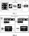
- a noise is illustrated by FIG. 2 which shows a scan 22 of a plane and a zoom 24 at a noise level of the same plane. Knowing the camera noise model, one can then emulate its behavior on synthetic depth data.
- the provided methods, programs, data structures, mediums and systems have many applications, for example in every machine learning based application through 3D sensor training data augmentation by artificially generating realistic training data from the synthetic one, e.g. in Autonomous Driving Simulators.
- the provided learning method is more accurate because it does not need to mathematically specify the physical noise model. One can let the machine learn by itself the model directly from the data. As opposed to existing modeling methods, the provided learning method relies on an adequately built learning dataset.
- the provided learning method offers a general pipeline that works for every depth sensor.
- the provided learning method thereby eliminates any need to mathematically model the noise for every sensor.
- the pipeline is the same and one may limit themselves to change the learning dataset according to the type of depth sensor whose noise is to be learnt.
- the noise-adding method is faster and achieves real-time performance as the mapping between the real and the synthetic spaces is already learnt offline.
- the provided methods, programs, data structures, mediums and systems learn to simulate any depth sensor. Instead of modeling the physical depth acquisition pipeline using signal propagation and reflection physics, example approaches bypass this step and learn directly the shift between the space of synthetic and real "noisy" depth maps.
- CNN convolutional Neural Network
- This processing is done offline. Once the mapping function between the synthetic and the real is learned, one can use it directly in an online manner to map the synthetic depth data to the real one. This pipeline is illustrated by FIG. 3 .
- the learning method may in examples be composed of two main steps:
- the first step of the approach is to generate a set of real and synthetic depth maps.
- a depth sensor e.g. the real depth sensor one would like to simulate
- N well-chosen scenes i.e. 3D known geometry, on n different viewpoints.
- One may put a still discriminative 3D calibration object (for example 3D chessboard) and/or a 2D calibration pattern while scanning the scenes and make it always visible to the camera. This may be used to compute the 3D pose of the camera at each key viewpoint so as to synthetize the corresponding noiseless depth map, by identifying in an acquired depth map said calibration element.
- An alternative of using the 3D calibration object, for estimating the camera pose may be to use the direct matching between the known 3D scene and the scanned one if the scene is textured/discriminative enough. It is noted that this may not work if one tries to match planer objects for example.
- An alternative to scenes with 3D objects would be to scan, at different depth levels, a white wall with a 2D pattern pasted on it (e.g. a chessboard).
- FIG. 4 shows a learning Database Generation Chart in line with the example.
- the learning method may apply this same pose to the virtual scene's camera using the same real camera intrinsic parameters.
- the learning method may then extract a synthetic depth map at each view point.
- the set of real and their corresponding synthetic depth maps may constitute the learning dataset.
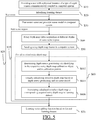
- FIG. 5 shows a flowchart of an example of the learning method.
- a user is provided at S10 with a depth sensor communicatively and wirelessly coupled to the processor of a computer system.
- the depth sensor is physically attached to the user, for example carried in his/her hands or attached to his head.
- a robot device may perform the method.
- several instances of a same model of depth sensors may be provided at S10, for example to several users. Instances of the method of FIG. 5 may then in examples be performed in parallel.
- the user launches at S20 a function to start the learning method, such that this initializes the learning dataset.
- This triggers a scheme S30-S60 implemented for one or more scenes.
- the flowchart of FIG. 5 shows a feedback S25, but the learning method may also be implemented for a single scene.
- the user enters at S30 the scene and provides a scene model to the computer system.
- the scene model may alternatively be acquired automatically by the computer system, at S30 or later such as upon S40, via retrieval, for example from a database and based on depth measurements.
- the example of the learning method then comprises a scheme S40-S60 performed for one or more scene regions.
- the flowchart of FIG. 5 shows a feedback S35, but the learning method may also be implemented for a single scene region.
- the user For each scene region, the user approaches the scene region and continuously acquires a depth video of the region (e.g. turning around the region, approaching the region and/or stepping back from the region). This operates an acquisition S40 at different depths of a same scene region.
- the video acquisition may be stopped or kept on between scene regions.
- the acquired depth map frames are sent at S50 (e.g. automatically) to the computer system.
- the method then comprises a scheme S60 performed for all received noisy depth map. Instances of scheme S60 may be performed iteratively (i.e. sequentially) and/or in parallel.
- Scheme S60 may be performed automatically by the computer system.
- Scheme S60 comprises determining S602 depth sensor positioning. This may be performed via identifying in a respective received noisy depth map a calibration object and/or a calibration pattern as discussed earlier.
- Scheme S60 may then calculate S604 fully virtually the noiseless depth map corresponding to the respective noisy depth map, based on such positioning and on the provided scene model (which, again, may have been previously provided by the user or retrieved automatically by the system, or which may be retrieved at this or any point based on depth maps sent and received at S50).
- Scheme S60 concludes formation of the learning dataset by associating at S606 calculated noiseless depth maps each to its corresponding acquired noisy depth map.
- the method of FIG. 5 learns the noise-adding function at S70 based on the formed learning dataset, in any way.
- FIG. 6 shows a flowchart of an example of the noise-adding method.
- the noise-adding method of FIG. 6 comprises virtually calculating S100 a noiseless depth map based on depth sensor positioning and on predetermined model of a scene. This may be triggered by a user or within a simulation process to simulate depth data acquisition.
- the predetermined model and a depth sensor positioning within said model may be provided in any way.
- the method then comprises applying S200, to the calculated noiseless depth map, a noise-adding function previously learnt and corresponding to the contemplated type of depth sensor.
- Learning the noise-adding function may be performed by regression learning. Such well-known learning can be performed simply and is thus fast and robust.
- Learning the noise-adding function may notably be performed within a space of (e.g. neural) networks comprising convolutional layers and/or deconvolutional layers.
- the learning e.g. S70
- the learning is configured to search a network made of a number (e.g. more than two, for example three or four) of convolutional layers that encode a signal - i.e. a noiseless depth map of the learning dataset - (e.g. and or followed by) a (e.g. same) number corresponding deconvolutional layers that decode the encoded signal.
- the encoding-decoding pipeline is configured to add the depth noise.
- the learning varies free parameters to perform the search.
- the number of layers, the sequence of layers e.g. a fixed and predetermined number of convolutional layers, for example three or four, and then a same number of deconvolutional layers
- the number and size of filters implemented by each layers e.g. 90 filters by layers and/or filters each of size 3 x 3) may all be fixed parameters of the learning.
- the (e.g. only) free parameters of the learning may then be the coefficients inside the filters.
- Convolutional layers allow a good extraction of local features, which is well-adapted for learning the noise in depth maps. Indeed, depth noise is at least most often a local perturbation in depth maps.
- the convolutional layers and/or deconvolutional layers may for example implement filters each of a size inferior to 10x10, preferably inferior to 5x5, preferably equal to 3x3. This allows a particularly good locality of the extraction of features, and thus an accurate and efficient learning.
- the learning model may be an end-to-end deep learning based neural network model. Such a network is well designed for this specific task of encoding/decoding a depth map image.
- the network may be learned to produce a noisy depth map from a synthetic one.
- the network may be composed of a chain of symmetric convolutional and deconvolutional layers.
- the convolutional layers serve as features extraction and depth map encoding part, while the deconvolutional layers serve as a decoder and a depth map reconstruction part.
- the layers pipeline may be fully convolutional with no pooling layers.
- the learning may employ small convolutional receptive fields to cover small image variations and thin noisy contour areas.
- D ⁇ , D are the noisy and the synthetic depth map images.
- Each model of a scene may be a 3D modeled object, for example a CAD object.
- a modeled object is any object defined by data stored e.g. in the database.
- the expression "modeled object" designates the data itself.
- the modeled objects may be defined by different kinds of data.
- the system may indeed be any combination of a CAD system, a CAE system, a CAM system, a PDM system and/or a PLM system.
- modeled objects are defined by corresponding data.
- One may accordingly speak of CAD object, PLM object, PDM object, CAE object, CAM object, CAD data, PLM data, PDM data, CAM data, CAE data.
- these systems are not exclusive one of the other, as a modeled object may be defined by data corresponding to any combination of these systems.
- a system may thus well be both a CAD and PLM system, as will be apparent from the definitions of such systems provided below.
- CAD system it is additionally meant any system adapted at least for designing a modeled object on the basis of a graphical representation of the modeled object, such as CATIA.
- the data defining a modeled object comprise data allowing the representation of the modeled object.
- a CAD system may for example provide a representation of CAD modeled objects using edges or lines, in certain cases with faces or surfaces. Lines, edges, or surfaces may be represented in various manners, e.g. non-uniform rational B-splines (NURBS).
- NURBS non-uniform rational B-splines
- a CAD file contains specifications, from which geometry may be generated, which in turn allows for a representation to be generated. Specifications of a modeled object may be stored in a single CAD file or multiple ones.
- the typical size of a file representing a modeled object in a CAD system is in the range of one Megabyte per part.
- a modeled object may typically be an assembly of thousands of parts.
- a modeled object may typically be a 3D modeled.
- 3D modeled object it is meant any object which is modeled by data allowing its 3D representation.
- a 3D representation allows the viewing of the part from all angles.
- a 3D modeled object when 3D represented, may be handled and turned around any of its axes, or around any axis in the screen on which the representation is displayed. This notably excludes 2D icons, which are not 3D modeled.
- the display of a 3D representation facilitates design (i.e. increases the speed at which designers statistically accomplish their task).
- the methods are computer-implemented. This means that the steps (or substantially all the steps) of the methods are executed by at least one computer, or any system alike. Thus, steps of the methods are performed by the computer, possibly fully automatically, or, semi-automatically. In examples, the triggering of at least some of the steps of the methods may be performed through user-computer interaction.
- the level of user-computer interaction required may depend on the level of automatism foreseen and put in balance with the need to implement user's wishes. In examples, this level may be user-defined and/or pre-defined.
- a typical example of computer-implementation of the methods is to perform the methods with a system adapted for this purpose.
- the system may comprise a processor coupled to a memory and a graphical user interface (GUI), the memory having recorded thereon a computer program comprising instructions for performing the methods.
- the memory may also store a database.
- the memory is any hardware adapted for such storage, possibly comprising several physical distinct parts (e.g. one for the program, and possibly one for the database).
- the system may further comprise a depth sensor coupled to the processor and configured to acquire a depth map of an instance for the 3D reconstruction.
- the system may also comprise a posing spot for the instance to pose during the acquisition.
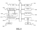
- FIG. 8 shows an example of the system, as computer system connected to a depth sensor.
- the system of the example comprises a central processing unit (CPU) 1010 connected to an internal communication BUS 1000, a random access memory (RAM) 1070 also connected to the BUS.
- the system is further provided with a graphical processing unit (GPU) 1110 which is associated with a video random access memory 1100 connected to the BUS.
- Video RAM 1100 is also known in the art as frame buffer.
- a mass storage device controller 1020 manages accesses to a mass memory device, such as hard drive 1030.
- Mass memory devices suitable for tangibly embodying computer program instructions and data include all forms of nonvolatile memory, including by way of example semiconductor memory devices, such as EPROM, EEPROM, and flash memory devices; magnetic disks such as internal hard disks and removable disks; magneto-optical disks; and CD-ROM disks 1040. Any of the foregoing may be supplemented by, or incorporated in, specially designed ASICs (application-specific integrated circuits).
- a network adapter 1050 manages accesses to a network 1060.
- the system may also include a depth sensor 1090.
- the computer program may comprise instructions executable by a computer, the instructions comprising means for causing the above system to perform the methods.
- the program may be recordable on any data storage medium, including the memory of the system.
- the program may for example be implemented in digital electronic circuitry, or in computer hardware, firmware, software, or in combinations of them.
- the program may be implemented as an apparatus, for example a product tangibly embodied in a machine-readable storage device for execution by a programmable processor. Method steps may be performed by a programmable processor executing a program of instructions to perform functions of the method by operating on input data and generating output.
- the processor may thus be programmable and coupled to receive data and instructions from, and to transmit data and instructions to, a data storage system, at least one input device, and at least one output device.
- the application program may be implemented in a high-level procedural or object-oriented programming language, or in assembly or machine language if desired. In any case, the language may be a compiled or interpreted language.
- the program may be a full installation program or an update program. Application of the program on the system results in any case in instructions for performing the method.
Landscapes
- Engineering & Computer Science (AREA)
- Physics & Mathematics (AREA)
- Theoretical Computer Science (AREA)
- General Physics & Mathematics (AREA)
- General Engineering & Computer Science (AREA)
- Evolutionary Computation (AREA)
- Molecular Biology (AREA)
- Computing Systems (AREA)
- Software Systems (AREA)
- Mathematical Physics (AREA)
- General Health & Medical Sciences (AREA)
- Data Mining & Analysis (AREA)
- Computational Linguistics (AREA)
- Health & Medical Sciences (AREA)
- Life Sciences & Earth Sciences (AREA)
- Artificial Intelligence (AREA)
- Biomedical Technology (AREA)
- Biophysics (AREA)
- Radar, Positioning & Navigation (AREA)
- Remote Sensing (AREA)
- Multimedia (AREA)
- Computer Vision & Pattern Recognition (AREA)
- Geometry (AREA)
- Computer Hardware Design (AREA)
- Electromagnetism (AREA)
- Signal Processing (AREA)
- Image Analysis (AREA)
- Image Processing (AREA)
- Length Measuring Devices By Optical Means (AREA)
Priority Applications (4)
| Application Number | Priority Date | Filing Date | Title |
|---|---|---|---|
| EP16306838.0A EP3343502B1 (en) | 2016-12-28 | 2016-12-28 | Depth sensor noise |
| US15/846,328 US10586309B2 (en) | 2016-12-28 | 2017-12-19 | Depth sensor noise |
| JP2017248111A JP7078392B2 (ja) | 2016-12-28 | 2017-12-25 | 深度センサノイズ |
| CN201711443854.7A CN108253941B (zh) | 2016-12-28 | 2017-12-27 | 深度传感器噪声 |
Applications Claiming Priority (1)
| Application Number | Priority Date | Filing Date | Title |
|---|---|---|---|
| EP16306838.0A EP3343502B1 (en) | 2016-12-28 | 2016-12-28 | Depth sensor noise |
Publications (2)
| Publication Number | Publication Date |
|---|---|
| EP3343502A1 EP3343502A1 (en) | 2018-07-04 |
| EP3343502B1 true EP3343502B1 (en) | 2019-02-20 |
Family
ID=57755158
Family Applications (1)
| Application Number | Title | Priority Date | Filing Date |
|---|---|---|---|
| EP16306838.0A Active EP3343502B1 (en) | 2016-12-28 | 2016-12-28 | Depth sensor noise |
Country Status (4)
| Country | Link |
|---|---|
| US (1) | US10586309B2 (enExample) |
| EP (1) | EP3343502B1 (enExample) |
| JP (1) | JP7078392B2 (enExample) |
| CN (1) | CN108253941B (enExample) |
Cited By (1)
| Publication number | Priority date | Publication date | Assignee | Title |
|---|---|---|---|---|
| US11302071B1 (en) | 2020-09-24 | 2022-04-12 | Eagle Technology, Llc | Artificial intelligence (AI) system using height seed initialization for extraction of digital elevation models (DEMs) and related methods |
Families Citing this family (26)
| Publication number | Priority date | Publication date | Assignee | Title |
|---|---|---|---|---|
| JP2017187882A (ja) | 2016-04-04 | 2017-10-12 | セイコーエプソン株式会社 | 画像処理に用いられるコンピュータープログラム |
| EP3293705B1 (en) * | 2016-09-12 | 2022-11-16 | Dassault Systèmes | 3d reconstruction of a real object from a depth map |
| EP3343502B1 (en) * | 2016-12-28 | 2019-02-20 | Dassault Systèmes | Depth sensor noise |
| US10387751B2 (en) * | 2017-01-12 | 2019-08-20 | Arizona Board Of Regents On Behalf Of Arizona State University | Methods, apparatuses, and systems for reconstruction-free image recognition from compressive sensors |
| US10929987B2 (en) | 2017-08-16 | 2021-02-23 | Nvidia Corporation | Learning rigidity of dynamic scenes for three-dimensional scene flow estimation |
| US10552665B2 (en) | 2017-12-12 | 2020-02-04 | Seiko Epson Corporation | Methods and systems for training an object detection algorithm using synthetic images |
| US11043006B1 (en) | 2017-12-29 | 2021-06-22 | Perceive Corporation | Use of machine-trained network for misalignment identification |
| US10769437B2 (en) | 2018-04-10 | 2020-09-08 | Seiko Epson Corporation | Adaptive sampling of training views |
| US10878285B2 (en) * | 2018-04-12 | 2020-12-29 | Seiko Epson Corporation | Methods and systems for shape based training for an object detection algorithm |
| RU2698402C1 (ru) * | 2018-08-30 | 2019-08-26 | Самсунг Электроникс Ко., Лтд. | Способ обучения сверточной нейронной сети для восстановления изображения и система для формирования карты глубины изображения (варианты) |
| US10634918B2 (en) | 2018-09-06 | 2020-04-28 | Seiko Epson Corporation | Internal edge verification |
| EP3674984B1 (en) * | 2018-12-29 | 2024-05-15 | Dassault Systèmes | Set of neural networks |
| US11308652B2 (en) * | 2019-02-25 | 2022-04-19 | Apple Inc. | Rendering objects to match camera noise |
| EP3736741B1 (en) | 2019-05-06 | 2025-02-12 | Dassault Systèmes | Experience learning in virtual world |
| EP3736740B1 (en) * | 2019-05-06 | 2025-02-12 | Dassault Systèmes | Experience learning in virtual world |
| CN110298916B (zh) * | 2019-06-21 | 2022-07-01 | 湖南大学 | 一种基于合成深度数据的三维人体重建方法 |
| JP7451946B2 (ja) | 2019-11-07 | 2024-03-19 | 株式会社アイシン | 制御装置 |
| CN111612071B (zh) * | 2020-05-21 | 2024-02-02 | 北京华睿盛德科技有限公司 | 一种从曲面零件阴影图生成深度图的深度学习方法 |
| US11587249B2 (en) | 2020-09-24 | 2023-02-21 | Eagle Technology, Llc | Artificial intelligence (AI) system and methods for generating estimated height maps from electro-optic imagery |
| US11238307B1 (en) | 2020-09-24 | 2022-02-01 | Eagle Technology, Llc | System for performing change detection within a 3D geospatial model based upon semantic change detection using deep learning and related methods |
| US11747468B2 (en) | 2020-09-24 | 2023-09-05 | Eagle Technology, Llc | System using a priori terrain height data for interferometric synthetic aperture radar (IFSAR) phase disambiguation and related methods |
| JP7468681B2 (ja) * | 2020-10-05 | 2024-04-16 | 日本電信電話株式会社 | 学習方法、学習装置、及びプログラム |
| CN113204010B (zh) * | 2021-03-15 | 2021-11-02 | 锋睿领创(珠海)科技有限公司 | 非视域目标检测方法、装置和存储介质 |
| CN113450295B (zh) * | 2021-06-15 | 2022-11-15 | 浙江大学 | 一种基于差分对比学习的深度图合成方法 |
| CN113628190B (zh) * | 2021-08-11 | 2024-03-15 | 跨维(深圳)智能数字科技有限公司 | 一种深度图去噪方法、装置、电子设备及介质 |
| JP7727563B2 (ja) * | 2022-01-20 | 2025-08-21 | 京セラ株式会社 | 深度情報処理装置、深度分布推定方法、深度分布検出システム及び学習済みモデル生成方法 |
Family Cites Families (22)
| Publication number | Priority date | Publication date | Assignee | Title |
|---|---|---|---|---|
| JP4872862B2 (ja) | 2006-09-28 | 2012-02-08 | ソニー株式会社 | 画像データ演算装置および方法、プログラム、並びに記録媒体 |
| US8295546B2 (en) * | 2009-01-30 | 2012-10-23 | Microsoft Corporation | Pose tracking pipeline |
| US8213680B2 (en) * | 2010-03-19 | 2012-07-03 | Microsoft Corporation | Proxy training data for human body tracking |
| WO2011142734A1 (en) * | 2010-05-11 | 2011-11-17 | Thomson Licensing | Comfort noise and film grain processing for 3 dimensional video |
| US8711206B2 (en) * | 2011-01-31 | 2014-04-29 | Microsoft Corporation | Mobile camera localization using depth maps |
| JP5976441B2 (ja) | 2011-08-03 | 2016-08-23 | 東芝メディカルシステムズ株式会社 | 超音波プローブ及び超音波診断装置 |
| US9031356B2 (en) * | 2012-03-20 | 2015-05-12 | Dolby Laboratories Licensing Corporation | Applying perceptually correct 3D film noise |
| JP6126437B2 (ja) | 2013-03-29 | 2017-05-10 | キヤノン株式会社 | 画像処理装置および画像処理方法 |
| US9613298B2 (en) | 2014-06-02 | 2017-04-04 | Microsoft Technology Licensing, Llc | Tracking using sensor data |
| WO2015193628A1 (en) * | 2014-06-19 | 2015-12-23 | Toshiba Research Europe Limited | Methods and systems for generating a three dimensional representation of a human body shape |
| WO2016050290A1 (en) | 2014-10-01 | 2016-04-07 | Metaio Gmbh | Method and system for determining at least one property related to at least part of a real environment |
| US10110881B2 (en) | 2014-10-30 | 2018-10-23 | Microsoft Technology Licensing, Llc | Model fitting from raw time-of-flight images |
| US9805294B2 (en) | 2015-02-12 | 2017-10-31 | Mitsubishi Electric Research Laboratories, Inc. | Method for denoising time-of-flight range images |
| CN105657402B (zh) * | 2016-01-18 | 2017-09-29 | 深圳市未来媒体技术研究院 | 一种深度图恢复方法 |
| CN105741267B (zh) * | 2016-01-22 | 2018-11-20 | 西安电子科技大学 | 聚类引导深度神经网络分类的多源图像变化检测方法 |
| US9460557B1 (en) * | 2016-03-07 | 2016-10-04 | Bao Tran | Systems and methods for footwear fitting |
| US9996981B1 (en) * | 2016-03-07 | 2018-06-12 | Bao Tran | Augmented reality system |
| US9959455B2 (en) * | 2016-06-30 | 2018-05-01 | The United States Of America As Represented By The Secretary Of The Army | System and method for face recognition using three dimensions |
| CN106251303A (zh) * | 2016-07-28 | 2016-12-21 | 同济大学 | 一种使用深度全卷积编码‑解码网络的图像降噪方法 |
| EP3293705B1 (en) * | 2016-09-12 | 2022-11-16 | Dassault Systèmes | 3d reconstruction of a real object from a depth map |
| EP3343502B1 (en) * | 2016-12-28 | 2019-02-20 | Dassault Systèmes | Depth sensor noise |
| US10796200B2 (en) * | 2018-04-27 | 2020-10-06 | Intel Corporation | Training image signal processors using intermediate loss functions |
-
2016
- 2016-12-28 EP EP16306838.0A patent/EP3343502B1/en active Active
-
2017
- 2017-12-19 US US15/846,328 patent/US10586309B2/en active Active
- 2017-12-25 JP JP2017248111A patent/JP7078392B2/ja active Active
- 2017-12-27 CN CN201711443854.7A patent/CN108253941B/zh active Active
Non-Patent Citations (1)
| Title |
|---|
| None * |
Cited By (1)
| Publication number | Priority date | Publication date | Assignee | Title |
|---|---|---|---|---|
| US11302071B1 (en) | 2020-09-24 | 2022-04-12 | Eagle Technology, Llc | Artificial intelligence (AI) system using height seed initialization for extraction of digital elevation models (DEMs) and related methods |
Also Published As
| Publication number | Publication date |
|---|---|
| JP2018109976A (ja) | 2018-07-12 |
| CN108253941B (zh) | 2021-11-12 |
| EP3343502A1 (en) | 2018-07-04 |
| US10586309B2 (en) | 2020-03-10 |
| US20180182071A1 (en) | 2018-06-28 |
| CN108253941A (zh) | 2018-07-06 |
| JP7078392B2 (ja) | 2022-05-31 |
Similar Documents
| Publication | Publication Date | Title |
|---|---|---|
| EP3343502B1 (en) | Depth sensor noise | |
| US20240153290A1 (en) | Systems and methods for extracting information about objects from scene information | |
| CA3232601C (en) | Browser optimized interactive electronic model based determination of attributes of a structure | |
| Whelan et al. | Deformation-based loop closure for large scale dense RGB-D SLAM | |
| CN107067473B (zh) | 用于对3d建模对象进行重构的方法、装置及系统 | |
| EP3401815B1 (en) | Determining an architectural layout | |
| Kumar et al. | Monocular fisheye camera depth estimation using sparse lidar supervision | |
| CN105701857B (zh) | 3d建模的对象的纹理化 | |
| Cui et al. | Dense depth-map estimation based on fusion of event camera and sparse LiDAR | |
| US20140132733A1 (en) | Backfilling Points in a Point Cloud | |
| EP2874118A1 (en) | Computing camera parameters | |
| US12154212B2 (en) | Generating environmental data | |
| Merras et al. | Multi-view 3D reconstruction and modeling of the unknown 3D scenes using genetic algorithms | |
| EP4162443A1 (en) | Three-dimensional map inconsistency detection using neural network | |
| Lehtola et al. | Indoor 3D: Overview on scanning and reconstruction methods | |
| Yan et al. | Radiance field learners as uav first-person viewers | |
| WO2025093093A1 (en) | Method for tracking construction site progress | |
| Wiemann et al. | Automatic Map Creation For Environment Modelling In Robotic Simulators. | |
| Samak et al. | When Digital Twins Meet Large Language Models: Realistic, Interactive, and Editable Simulation for Autonomous Driving | |
| Singh et al. | Accurate three-dimensional documentation of distinct sites | |
| JP2024013228A (ja) | ビルディングシーンのセグメント化 | |
| Abdollahi Taromsari | Pianificazione del percorso e selezione delle viste efficienti per sistemi autonomi di Digital Twin aerei | |
| Nešić et al. | A Generative Model for the Creation of Large Synthetic Image Datasets Used for Distance Estimation | |
| Wiemann | Automatic Generation of 3D Polygon Maps for Mobile Robots |
Legal Events
| Date | Code | Title | Description |
|---|---|---|---|
| PUAI | Public reference made under article 153(3) epc to a published international application that has entered the european phase |
Free format text: ORIGINAL CODE: 0009012 |
|
| STAA | Information on the status of an ep patent application or granted ep patent |
Free format text: STATUS: REQUEST FOR EXAMINATION WAS MADE |
|
| 17P | Request for examination filed |
Effective date: 20180103 |
|
| AK | Designated contracting states |
Kind code of ref document: A1 Designated state(s): AL AT BE BG CH CY CZ DE DK EE ES FI FR GB GR HR HU IE IS IT LI LT LU LV MC MK MT NL NO PL PT RO RS SE SI SK SM TR |
|
| AX | Request for extension of the european patent |
Extension state: BA ME |
|
| GRAP | Despatch of communication of intention to grant a patent |
Free format text: ORIGINAL CODE: EPIDOSNIGR1 |
|
| STAA | Information on the status of an ep patent application or granted ep patent |
Free format text: STATUS: GRANT OF PATENT IS INTENDED |
|
| RIC1 | Information provided on ipc code assigned before grant |
Ipc: G06N 3/08 20060101ALI20180712BHEP Ipc: G06N 3/04 20060101ALI20180712BHEP Ipc: G06T 5/00 20060101AFI20180712BHEP |
|
| INTG | Intention to grant announced |
Effective date: 20180814 |
|
| GRAS | Grant fee paid |
Free format text: ORIGINAL CODE: EPIDOSNIGR3 |
|
| GRAA | (expected) grant |
Free format text: ORIGINAL CODE: 0009210 |
|
| STAA | Information on the status of an ep patent application or granted ep patent |
Free format text: STATUS: THE PATENT HAS BEEN GRANTED |
|
| AK | Designated contracting states |
Kind code of ref document: B1 Designated state(s): AL AT BE BG CH CY CZ DE DK EE ES FI FR GB GR HR HU IE IS IT LI LT LU LV MC MK MT NL NO PL PT RO RS SE SI SK SM TR |
|
| RBV | Designated contracting states (corrected) |
Designated state(s): AL AT BE BG CH CY CZ DE DK EE ES FI FR GB GR HR HU IE IS IT LI LT LU LV MC MK MT NL NO PL PT RO RS SE SI SK SM TR |
|
| REG | Reference to a national code |
Ref country code: GB Ref legal event code: FG4D |
|
| REG | Reference to a national code |
Ref country code: CH Ref legal event code: EP |
|
| REG | Reference to a national code |
Ref country code: DE Ref legal event code: R096 Ref document number: 602016010113 Country of ref document: DE |
|
| REG | Reference to a national code |
Ref country code: AT Ref legal event code: REF Ref document number: 1099197 Country of ref document: AT Kind code of ref document: T Effective date: 20190315 |
|
| REG | Reference to a national code |
Ref country code: IE Ref legal event code: FG4D |
|
| REG | Reference to a national code |
Ref country code: SE Ref legal event code: TRGR |
|
| REG | Reference to a national code |
Ref country code: LT Ref legal event code: MG4D |
|
| REG | Reference to a national code |
Ref country code: NL Ref legal event code: MP Effective date: 20190220 |
|
| PG25 | Lapsed in a contracting state [announced via postgrant information from national office to epo] |
Ref country code: FI Free format text: LAPSE BECAUSE OF FAILURE TO SUBMIT A TRANSLATION OF THE DESCRIPTION OR TO PAY THE FEE WITHIN THE PRESCRIBED TIME-LIMIT Effective date: 20190220 Ref country code: LT Free format text: LAPSE BECAUSE OF FAILURE TO SUBMIT A TRANSLATION OF THE DESCRIPTION OR TO PAY THE FEE WITHIN THE PRESCRIBED TIME-LIMIT Effective date: 20190220 Ref country code: PT Free format text: LAPSE BECAUSE OF FAILURE TO SUBMIT A TRANSLATION OF THE DESCRIPTION OR TO PAY THE FEE WITHIN THE PRESCRIBED TIME-LIMIT Effective date: 20190620 Ref country code: NO Free format text: LAPSE BECAUSE OF FAILURE TO SUBMIT A TRANSLATION OF THE DESCRIPTION OR TO PAY THE FEE WITHIN THE PRESCRIBED TIME-LIMIT Effective date: 20190520 |
|
| PG25 | Lapsed in a contracting state [announced via postgrant information from national office to epo] |
Ref country code: RS Free format text: LAPSE BECAUSE OF FAILURE TO SUBMIT A TRANSLATION OF THE DESCRIPTION OR TO PAY THE FEE WITHIN THE PRESCRIBED TIME-LIMIT Effective date: 20190220 Ref country code: LV Free format text: LAPSE BECAUSE OF FAILURE TO SUBMIT A TRANSLATION OF THE DESCRIPTION OR TO PAY THE FEE WITHIN THE PRESCRIBED TIME-LIMIT Effective date: 20190220 Ref country code: NL Free format text: LAPSE BECAUSE OF FAILURE TO SUBMIT A TRANSLATION OF THE DESCRIPTION OR TO PAY THE FEE WITHIN THE PRESCRIBED TIME-LIMIT Effective date: 20190220 Ref country code: GR Free format text: LAPSE BECAUSE OF FAILURE TO SUBMIT A TRANSLATION OF THE DESCRIPTION OR TO PAY THE FEE WITHIN THE PRESCRIBED TIME-LIMIT Effective date: 20190521 Ref country code: HR Free format text: LAPSE BECAUSE OF FAILURE TO SUBMIT A TRANSLATION OF THE DESCRIPTION OR TO PAY THE FEE WITHIN THE PRESCRIBED TIME-LIMIT Effective date: 20190220 Ref country code: IS Free format text: LAPSE BECAUSE OF FAILURE TO SUBMIT A TRANSLATION OF THE DESCRIPTION OR TO PAY THE FEE WITHIN THE PRESCRIBED TIME-LIMIT Effective date: 20190620 Ref country code: BG Free format text: LAPSE BECAUSE OF FAILURE TO SUBMIT A TRANSLATION OF THE DESCRIPTION OR TO PAY THE FEE WITHIN THE PRESCRIBED TIME-LIMIT Effective date: 20190520 |
|
| REG | Reference to a national code |
Ref country code: AT Ref legal event code: MK05 Ref document number: 1099197 Country of ref document: AT Kind code of ref document: T Effective date: 20190220 |
|
| PG25 | Lapsed in a contracting state [announced via postgrant information from national office to epo] |
Ref country code: EE Free format text: LAPSE BECAUSE OF FAILURE TO SUBMIT A TRANSLATION OF THE DESCRIPTION OR TO PAY THE FEE WITHIN THE PRESCRIBED TIME-LIMIT Effective date: 20190220 Ref country code: DK Free format text: LAPSE BECAUSE OF FAILURE TO SUBMIT A TRANSLATION OF THE DESCRIPTION OR TO PAY THE FEE WITHIN THE PRESCRIBED TIME-LIMIT Effective date: 20190220 Ref country code: ES Free format text: LAPSE BECAUSE OF FAILURE TO SUBMIT A TRANSLATION OF THE DESCRIPTION OR TO PAY THE FEE WITHIN THE PRESCRIBED TIME-LIMIT Effective date: 20190220 Ref country code: CZ Free format text: LAPSE BECAUSE OF FAILURE TO SUBMIT A TRANSLATION OF THE DESCRIPTION OR TO PAY THE FEE WITHIN THE PRESCRIBED TIME-LIMIT Effective date: 20190220 Ref country code: RO Free format text: LAPSE BECAUSE OF FAILURE TO SUBMIT A TRANSLATION OF THE DESCRIPTION OR TO PAY THE FEE WITHIN THE PRESCRIBED TIME-LIMIT Effective date: 20190220 Ref country code: SK Free format text: LAPSE BECAUSE OF FAILURE TO SUBMIT A TRANSLATION OF THE DESCRIPTION OR TO PAY THE FEE WITHIN THE PRESCRIBED TIME-LIMIT Effective date: 20190220 Ref country code: AL Free format text: LAPSE BECAUSE OF FAILURE TO SUBMIT A TRANSLATION OF THE DESCRIPTION OR TO PAY THE FEE WITHIN THE PRESCRIBED TIME-LIMIT Effective date: 20190220 |
|
| REG | Reference to a national code |
Ref country code: DE Ref legal event code: R097 Ref document number: 602016010113 Country of ref document: DE |
|
| PG25 | Lapsed in a contracting state [announced via postgrant information from national office to epo] |
Ref country code: PL Free format text: LAPSE BECAUSE OF FAILURE TO SUBMIT A TRANSLATION OF THE DESCRIPTION OR TO PAY THE FEE WITHIN THE PRESCRIBED TIME-LIMIT Effective date: 20190220 Ref country code: SM Free format text: LAPSE BECAUSE OF FAILURE TO SUBMIT A TRANSLATION OF THE DESCRIPTION OR TO PAY THE FEE WITHIN THE PRESCRIBED TIME-LIMIT Effective date: 20190220 |
|
| PLBE | No opposition filed within time limit |
Free format text: ORIGINAL CODE: 0009261 |
|
| STAA | Information on the status of an ep patent application or granted ep patent |
Free format text: STATUS: NO OPPOSITION FILED WITHIN TIME LIMIT |
|
| PG25 | Lapsed in a contracting state [announced via postgrant information from national office to epo] |
Ref country code: AT Free format text: LAPSE BECAUSE OF FAILURE TO SUBMIT A TRANSLATION OF THE DESCRIPTION OR TO PAY THE FEE WITHIN THE PRESCRIBED TIME-LIMIT Effective date: 20190220 |
|
| 26N | No opposition filed |
Effective date: 20191121 |
|
| PG25 | Lapsed in a contracting state [announced via postgrant information from national office to epo] |
Ref country code: TR Free format text: LAPSE BECAUSE OF FAILURE TO SUBMIT A TRANSLATION OF THE DESCRIPTION OR TO PAY THE FEE WITHIN THE PRESCRIBED TIME-LIMIT Effective date: 20190220 |
|
| REG | Reference to a national code |
Ref country code: CH Ref legal event code: PL |
|
| REG | Reference to a national code |
Ref country code: BE Ref legal event code: MM Effective date: 20191231 |
|
| PG25 | Lapsed in a contracting state [announced via postgrant information from national office to epo] |
Ref country code: MC Free format text: LAPSE BECAUSE OF FAILURE TO SUBMIT A TRANSLATION OF THE DESCRIPTION OR TO PAY THE FEE WITHIN THE PRESCRIBED TIME-LIMIT Effective date: 20190220 |
|
| PG25 | Lapsed in a contracting state [announced via postgrant information from national office to epo] |
Ref country code: LU Free format text: LAPSE BECAUSE OF NON-PAYMENT OF DUE FEES Effective date: 20191228 Ref country code: IE Free format text: LAPSE BECAUSE OF NON-PAYMENT OF DUE FEES Effective date: 20191228 |
|
| PG25 | Lapsed in a contracting state [announced via postgrant information from national office to epo] |
Ref country code: CH Free format text: LAPSE BECAUSE OF NON-PAYMENT OF DUE FEES Effective date: 20191231 Ref country code: BE Free format text: LAPSE BECAUSE OF NON-PAYMENT OF DUE FEES Effective date: 20191231 Ref country code: LI Free format text: LAPSE BECAUSE OF NON-PAYMENT OF DUE FEES Effective date: 20191231 |
|
| PG25 | Lapsed in a contracting state [announced via postgrant information from national office to epo] |
Ref country code: CY Free format text: LAPSE BECAUSE OF FAILURE TO SUBMIT A TRANSLATION OF THE DESCRIPTION OR TO PAY THE FEE WITHIN THE PRESCRIBED TIME-LIMIT Effective date: 20190220 |
|
| PG25 | Lapsed in a contracting state [announced via postgrant information from national office to epo] |
Ref country code: MT Free format text: LAPSE BECAUSE OF FAILURE TO SUBMIT A TRANSLATION OF THE DESCRIPTION OR TO PAY THE FEE WITHIN THE PRESCRIBED TIME-LIMIT Effective date: 20190220 Ref country code: HU Free format text: LAPSE BECAUSE OF FAILURE TO SUBMIT A TRANSLATION OF THE DESCRIPTION OR TO PAY THE FEE WITHIN THE PRESCRIBED TIME-LIMIT; INVALID AB INITIO Effective date: 20161228 |
|
| PG25 | Lapsed in a contracting state [announced via postgrant information from national office to epo] |
Ref country code: SI Free format text: LAPSE BECAUSE OF FAILURE TO SUBMIT A TRANSLATION OF THE DESCRIPTION OR TO PAY THE FEE WITHIN THE PRESCRIBED TIME-LIMIT Effective date: 20190220 |
|
| PG25 | Lapsed in a contracting state [announced via postgrant information from national office to epo] |
Ref country code: MK Free format text: LAPSE BECAUSE OF FAILURE TO SUBMIT A TRANSLATION OF THE DESCRIPTION OR TO PAY THE FEE WITHIN THE PRESCRIBED TIME-LIMIT Effective date: 20190220 |
|
| P01 | Opt-out of the competence of the unified patent court (upc) registered |
Effective date: 20230527 |
|
| PGFP | Annual fee paid to national office [announced via postgrant information from national office to epo] |
Ref country code: GB Payment date: 20241226 Year of fee payment: 9 |
|
| PGFP | Annual fee paid to national office [announced via postgrant information from national office to epo] |
Ref country code: FR Payment date: 20241224 Year of fee payment: 9 |
|
| PGFP | Annual fee paid to national office [announced via postgrant information from national office to epo] |
Ref country code: SE Payment date: 20241219 Year of fee payment: 9 |
|
| PGFP | Annual fee paid to national office [announced via postgrant information from national office to epo] |
Ref country code: IT Payment date: 20241227 Year of fee payment: 9 |
|
| PGFP | Annual fee paid to national office [announced via postgrant information from national office to epo] |
Ref country code: DE Payment date: 20251211 Year of fee payment: 10 |