EP3343205A1 - A system for analysing the chemical composition of a target material and corresponding process - Google Patents
A system for analysing the chemical composition of a target material and corresponding process Download PDFInfo
- Publication number
- EP3343205A1 EP3343205A1 EP16382678.7A EP16382678A EP3343205A1 EP 3343205 A1 EP3343205 A1 EP 3343205A1 EP 16382678 A EP16382678 A EP 16382678A EP 3343205 A1 EP3343205 A1 EP 3343205A1
- Authority
- EP
- European Patent Office
- Prior art keywords
- light
- plasma
- target material
- redirecting means
- light redirecting
- Prior art date
- Legal status (The legal status is an assumption and is not a legal conclusion. Google has not performed a legal analysis and makes no representation as to the accuracy of the status listed.)
- Withdrawn
Links
- 239000013077 target material Substances 0.000 title claims abstract description 52
- 239000000126 substance Substances 0.000 title claims abstract description 22
- 239000000203 mixture Substances 0.000 title claims abstract description 21
- 238000000034 method Methods 0.000 title claims description 9
- 230000003595 spectral effect Effects 0.000 claims abstract description 23
- 238000001514 detection method Methods 0.000 claims description 9
- 230000001939 inductive effect Effects 0.000 claims description 3
- 238000011144 upstream manufacturing Methods 0.000 claims description 3
- 230000003287 optical effect Effects 0.000 description 19
- 238000004458 analytical method Methods 0.000 description 11
- 238000002536 laser-induced breakdown spectroscopy Methods 0.000 description 11
- 238000007689 inspection Methods 0.000 description 5
- 230000000712 assembly Effects 0.000 description 4
- 238000000429 assembly Methods 0.000 description 4
- 239000000463 material Substances 0.000 description 4
- 230000001681 protective effect Effects 0.000 description 4
- 239000000835 fiber Substances 0.000 description 3
- 230000003068 static effect Effects 0.000 description 3
- 238000010276 construction Methods 0.000 description 2
- 239000013307 optical fiber Substances 0.000 description 2
- 239000000523 sample Substances 0.000 description 2
- 230000035945 sensitivity Effects 0.000 description 2
- 239000004411 aluminium Substances 0.000 description 1
- 229910052782 aluminium Inorganic materials 0.000 description 1
- XAGFODPZIPBFFR-UHFFFAOYSA-N aluminium Chemical compound [Al] XAGFODPZIPBFFR-UHFFFAOYSA-N 0.000 description 1
- 230000005540 biological transmission Effects 0.000 description 1
- 238000007664 blowing Methods 0.000 description 1
- 230000001419 dependent effect Effects 0.000 description 1
- 238000005265 energy consumption Methods 0.000 description 1
- 238000010304 firing Methods 0.000 description 1
- 239000002223 garnet Substances 0.000 description 1
- 238000003384 imaging method Methods 0.000 description 1
- 230000010354 integration Effects 0.000 description 1
- 238000004519 manufacturing process Methods 0.000 description 1
- 229910052751 metal Inorganic materials 0.000 description 1
- 239000002184 metal Substances 0.000 description 1
- 239000002245 particle Substances 0.000 description 1
- 238000004064 recycling Methods 0.000 description 1
- 239000007787 solid Substances 0.000 description 1
- 238000004611 spectroscopical analysis Methods 0.000 description 1
- 230000002195 synergetic effect Effects 0.000 description 1
- 229910052727 yttrium Inorganic materials 0.000 description 1
- VWQVUPCCIRVNHF-UHFFFAOYSA-N yttrium atom Chemical compound [Y] VWQVUPCCIRVNHF-UHFFFAOYSA-N 0.000 description 1
Images


Classifications
-
- G—PHYSICS
- G01—MEASURING; TESTING
- G01N—INVESTIGATING OR ANALYSING MATERIALS BY DETERMINING THEIR CHEMICAL OR PHYSICAL PROPERTIES
- G01N21/00—Investigating or analysing materials by the use of optical means, i.e. using sub-millimetre waves, infrared, visible or ultraviolet light
- G01N21/62—Systems in which the material investigated is excited whereby it emits light or causes a change in wavelength of the incident light
- G01N21/71—Systems in which the material investigated is excited whereby it emits light or causes a change in wavelength of the incident light thermally excited
- G01N21/718—Laser microanalysis, i.e. with formation of sample plasma
-
- G—PHYSICS
- G01—MEASURING; TESTING
- G01J—MEASUREMENT OF INTENSITY, VELOCITY, SPECTRAL CONTENT, POLARISATION, PHASE OR PULSE CHARACTERISTICS OF INFRARED, VISIBLE OR ULTRAVIOLET LIGHT; COLORIMETRY; RADIATION PYROMETRY
- G01J3/00—Spectrometry; Spectrophotometry; Monochromators; Measuring colours
- G01J3/02—Details
- G01J3/0205—Optical elements not provided otherwise, e.g. optical manifolds, diffusers, windows
- G01J3/021—Optical elements not provided otherwise, e.g. optical manifolds, diffusers, windows using plane or convex mirrors, parallel phase plates, or particular reflectors
-
- G—PHYSICS
- G01—MEASURING; TESTING
- G01J—MEASUREMENT OF INTENSITY, VELOCITY, SPECTRAL CONTENT, POLARISATION, PHASE OR PULSE CHARACTERISTICS OF INFRARED, VISIBLE OR ULTRAVIOLET LIGHT; COLORIMETRY; RADIATION PYROMETRY
- G01J3/00—Spectrometry; Spectrophotometry; Monochromators; Measuring colours
- G01J3/28—Investigating the spectrum
- G01J3/443—Emission spectrometry
-
- B—PERFORMING OPERATIONS; TRANSPORTING
- B07—SEPARATING SOLIDS FROM SOLIDS; SORTING
- B07C—POSTAL SORTING; SORTING INDIVIDUAL ARTICLES, OR BULK MATERIAL FIT TO BE SORTED PIECE-MEAL, e.g. BY PICKING
- B07C5/00—Sorting according to a characteristic or feature of the articles or material being sorted, e.g. by control effected by devices which detect or measure such characteristic or feature; Sorting by manually actuated devices, e.g. switches
- B07C5/34—Sorting according to other particular properties
- B07C5/342—Sorting according to other particular properties according to optical properties, e.g. colour
-
- G—PHYSICS
- G01—MEASURING; TESTING
- G01N—INVESTIGATING OR ANALYSING MATERIALS BY DETERMINING THEIR CHEMICAL OR PHYSICAL PROPERTIES
- G01N21/00—Investigating or analysing materials by the use of optical means, i.e. using sub-millimetre waves, infrared, visible or ultraviolet light
- G01N21/84—Systems specially adapted for particular applications
- G01N2021/845—Objects on a conveyor
- G01N2021/8455—Objects on a conveyor and using position detectors
-
- G—PHYSICS
- G01—MEASURING; TESTING
- G01N—INVESTIGATING OR ANALYSING MATERIALS BY DETERMINING THEIR CHEMICAL OR PHYSICAL PROPERTIES
- G01N2201/00—Features of devices classified in G01N21/00
- G01N2201/10—Scanning
- G01N2201/104—Mechano-optical scan, i.e. object and beam moving
- G01N2201/1042—X, Y scan, i.e. object moving in X, beam in Y
-
- G—PHYSICS
- G01—MEASURING; TESTING
- G01N—INVESTIGATING OR ANALYSING MATERIALS BY DETERMINING THEIR CHEMICAL OR PHYSICAL PROPERTIES
- G01N2201/00—Features of devices classified in G01N21/00
- G01N2201/10—Scanning
- G01N2201/104—Mechano-optical scan, i.e. object and beam moving
- G01N2201/1047—Mechano-optical scan, i.e. object and beam moving with rotating optics and moving stage
Definitions
- the invention relates to a system for analysing the chemical composition of a target material
- a laser system comprising at least one laser for providing a laser beam of laser pulses, at least one scanner assembly for directing said laser beam onto said target material such as to produce luminous plasma on said target material and to collect the light emitted by said plasma
- said scanner assembly comprising: first focusing means, arranged downstream of said laser system, and a light collector arranged downstream of said first focusing means for collecting the light emitted by said plasma passing through said first focusing means, and a spectral analyser for receiving light from said light collector for isolating and measuring at least one selected emission band from the light collected by said light collector.
- the invention further refers to a process for analysing the chemical composition of a target material with a system according to the invention, the process comprising the steps of: emitting a laser beam on to the surface of said target material, such as to produce luminous plasma on said target material and collecting the light emitted by said plasma, and isolating and measuring at least one selected emission band contained in the light emitted by said plasma.
- the spectroscopy technique most commonly known as Laser-Induced Breakdown Spectroscopy (LIBS)
- LIBS Laser-Induced Breakdown Spectroscopy
- Document US 2003/0132142 A1 discloses a system for sorting randomly positioned, irregularly, scrap particles are fed onto a moving conveyor, and are ejected into different bins according to their chemical composition, as determined by a LIBS system.
- the system of US 2003/0132142 A1 includes, amongst other elements, a laser system, a scanner system to direct focused laser pulses to a selected location within a two-dimensional target area on the surface of a conveyor, a light collector for receiving light in the target area from the plasma generated by the laser pulses, and a light distribution and spectral analyser system for isolating and measuring at least one selected emission band contained within the light from the LIBS plasma.
- the collection of light from a static plasma discharge can be performed using conventional imaging optics, which couple the emitted light to the spectral analyser.
- the efficient collection of light from an extended surface is substantially more complex.
- the position of the plasma spot can vary across a large surface, it is difficult to use high aperture optics to collect light, while maintaining an acceptable depth of field and good transmission over the ultraviolet-visible spectral range.
- the preferred implementation of the light collector is configured as a plurality of optical fibres distributed separately within the scanner housing for collecting the light from the LIBS plasma.
- this approach presents several disadvantages. First, the light collection efficiency of a single fibre covering a large area compared to its core diameter is low.
- the optical throughput of the system is further reduced due to the need for transmitting the light received from multiple fibres, to the spectral analyser.
- This step usually involves the use of an integrating sphere, or an equivalent arrangement, which results in a drastic reduction of the optical efficiency of the system.
- the use of multiple fibres to collect light has disadvantages in terms of cost, complexity, and reliability.
- the invention has the further object of improving the service life of the system.
- said scanner assembly further comprises at least first light redirecting means arranged downstream of said laser system, said first light redirecting means, being configured such as to let the light pass therethrough when the light falls on one first side of said first light redirecting means and to redirect at least part of the light when the light falls on a second side opposite to said first side, and in that said first light redirecting means are arranged in said system to gather said light emitted by said plasma, collinearly with said laser beam directed onto said target material and to redirect at least part of said light emitted by said plasma onto said first focusing means.
- a major issue in the design of a LIBS system able to analyse a large surface area deals with the efficient collection of the light emitted by the plasma. Since the duration of the plasma created by the laser shot is just a few microseconds, it is extremely important to collect as much as light as possible, to increase the sensitivity of the system, and to minimise the required laser power. Reducing the laser power allows using cheaper and more compact lasers, while allow increasing the service life of the optical components. Therefore, an efficient collection of light results in a more sensitive, more reliable and less expensive LIBS system.
- the target material can be for example, among others unsorted scrap material or simply unsorted parts with different chemical compositions. It is particularly desirable to efficiently separate metal and other scrap into families with similar chemical composition, since scrap sorted in this way has a higher value for recycling, than mixed scrap with dissimilar chemical composition. It is also desirable in manufacturing processes to perform a fast, an in-line analysis of materials being produced, to confirm the composition and/or quality of those materials.
- the invention further includes a number of preferred features that are object of the dependent claims and the utility of which will be highlighted hereinafter in the detailed description of an embodiment of the invention.
- the system further comprises second light redirecting means arranged downstream of said first light redirecting means, for redirecting said light emitted by said plasma, onto said first focusing means either directly or via said second side of said first light redirecting means. Thanks to this second light redirecting means, both the laser system and the spectral analyser can be arranged, if so wanted, parallel to one another, and therefore a more compact system is achieved.
- the system further comprises third light redirecting means arranged between said laser system and said first light redirecting means for redirecting said laser beam onto said first side of said first light redirecting means. Thanks to this configuration, it is possible to ensure a high throughput of the optical collection system while varying the position of the focusing spot. This allows covering a large inspection area with a high optical efficiency, without the need for introducing additional optical elements.
- said third light redirecting means is rotatably reciprocatingly mounted around an axis.
- said first light redirecting means is one of the group of a perforated mirror, a semitransparent mirror or a dichroic mirror. This provides an easy construction. Additionally, in the case of the perforated mirror a very simple an unexpensive configuration can be achieved.
- the second and third light redirecting means is a mirror.
- the system further comprises laser beam expanding means arranged between said laser system and said third light redirecting means for expanding said laser beam before it falls onto said third light redirecting means.
- laser beam expanding means arranged between said laser system and said third light redirecting means for expanding said laser beam before it falls onto said third light redirecting means.
- the system further comprises second focusing means arranged between said third light redirecting means and said first light redirecting means.
- This second focusing means focuses the laser beam coming from the third light redirecting means to form a small spot lying on or close to the target material. Again, this enhances the efficacy of the laser beam producing the plasma. Therefore, again the laser power required can be reduced. This leads again to the synergistic effect of less damage on the system parts and therefore to a longer service life.
- the system according to the invention further comprises a supporting surface for supporting said target material and said supporting surface and said scanner assembly are movable relative to each other.
- the supporting surface is movable along a longitudinal direction.
- said scanner assembly is arranged over said supporting surface and said second light redirecting means is rotatably reciprocatingly mounted around an axis parallel to said longitudinal direction such as to scan the width of said supporting surface in a plane perpendicular to said longitudinal direction.
- the system further comprises an array of detection devices arranged upstream of said scanner assembly and covering the width of said supporting surface, said detection devices being a plurality of inductive or capacitive sensors.
- said detection device is arranged below said supporting surface.
- the invention also provides a process for analysing the chemical composition of a target material characterised in that the light emitted by said plasma is collected collinearly with at least the section of the laser beam falling on said target material for producing the luminous plasma and redirected onto the aperture of the light collector of the system.
- Figure 1 shows a first embodiment of the system 1 for analysing the chemical composition of a target material 100 of the invention.
- the target material 100 is preferably a metallic scrap part or parts placed on a static supporting surface 26.
- the system 1 comprises mainly following elements: a laser system 2, a scanner assembly, a spectral analyser 10 and finally control means 28, not shown in detail, responsible for controlling the operation of the laser system 2, the scanner assembly and the spectral analyser 10. All these elements are arranged within a housing 30 comprising a protective window 32 through which laser light can be projected onto the target material 100 to be analysed.
- the laser system 2 comprises at least one laser device.
- This laser device provides a laser beam 4 of laser pulses within a short time interval which in the figures is indicated with arrows made from two converging segments.
- the laser system uses a solid-state laser, like a neodymium-doped yttrium aluminium garnet, commonly known in the art as Nd:YAG laser.
- the scanner assembly of system of the invention is configured to direct the laser beam 4 coming from the laser system 2 onto the target material 100.
- This laser beam 4 has an energy level that is high enough to produce luminous plasma by vaporising the target material 100 but lower as the systems known in the art.
- the light emitted by the target material 100 and the collecting path thereof is indicated in the figures with solid arrows.
- to produce luminous plasma is desirable to provide a plurality of pulses within a short time interval such that each of the pulses falls on the target material 100 to be analysed within a distance of less than few hundred micrometers.
- up to 4 laser pulses may be directed on the target material 100, with an interpulse delay of 0.5 to 100 microseconds, using one or several triggerable Nd:YAG laser devices.
- the system 1 comprises a plurality of scanner assemblies.
- the control system preferably triggers the firing of each laser system, such that one and only one laser fires as any one time, and such that the light from one, and one only scanner assembly, reaches the spectral analyser system at any one time.
- the scanner assembly comprises first focusing means 6 arranged downstream of the laser system 2.
- the focusing means is, e.g. a focusing lens, causes the laser beam 4 to converge in order to form a spot at a defined distance of the lens.
- a light collector 8 is arranged downstream of the first focusing means 6. This light collector 8, which is preferably a single optical fibre, or a compact fibre bundle of optical fibres, collects the light emitted by the plasma passing first through the first focusing means 6 before reaching the light collector 8.
- the scanner assembly further comprises first light redirecting means 12 arranged downstream of the laser system 2.
- the first light redirecting means 12 are configured to let the laser light pass therethrough when the light falls on one first side 14 thereof and to redirect or deflect at least part of the light emitted by the surface on which the laser light falls on, when the returning light falls on a second side 16 opposite to the first side 14.
- the first light redirecting means 12 is one of the group of a perforated mirror, a semitransparent mirror or a dichroic mirror.
- the first light redirecting means 12 is arranged between the laser system 2 and the first focusing means 6.
- the first light redirecting means 12 gather the light emitted by the plasma, collinearly with the laser beam 4 responsible of producing the luminous plasma on the target material 100 and redirect at least part of this light emitted by the plasma onto the first focusing means 6 and from here to the light collector 8.
- the spectral analyser 10 is provided for receiving the light from the light collector 8 and for isolating and measuring at least one selected emission band from the light emitted by the plasma and collected via the light collector 8.
- the spectral analyser 10 is in the form of a Rowland circle polychromator with detectors placed at one or more spectral regions of interest.
- Each of the detectors is preferably a multichannel photomultipler tube (PMT) arranged such that each of the PMT channels accumulates the light from a small spectral range, and where the totality of the multiple channels in each multichannel PMT cover a proportionally wider spectral range.
- PMT photomultipler tube
- the optical fibres from each of the scanner assemblies are arranged to form a line at the entrance slit of the polychromator, such that a given emission wavelength emitted from each fibre, will fall on the same channel of a given PMT.
- PMT are advantageous in this respect, due to their tall photosensitive channels, allowing the same wavelength emanating from a plurality of optical fibres arranged in a line at the entrance slit of the spectral analyser to fall on the same channel of a given PMT.
- both the laser system 2 and the spectral analyser are timely and operatively controlled by the control means 28, e.g. a computer or the like.
- the control means 28 includes the hardware and electronic components necessary not only for controlling but also to properly operating the other elements of the system.
- the light emitted by the plasma can be collinearly collected.
- This collinearity allows lower laser energy to be used, improves the sensitivity and clearly simplifies the construction of the system.
- an integration sphere is needed to collect the light before it being introduced in the spectral analyser.
- the system of figure 1 is static, that is, neither the system 1 nor the target material 100 move relative to each other during operation and analysis. However, it is contemplated that one of both could move or event both elements could move during the analysis in order to measure different points of the target material 100.
- the system 1 further comprises second light redirecting means 18 arranged downstream of the first light redirecting means 12.
- This second light redirecting means 18 is a reflecting surface such as a mirror, or any other reflecting surface made of a material able to redirect the laser beam and to withstand the heat generated by the laser beam 4. Thanks to this element, the light emitted by the plasma is redirected or deflected onto the first focusing means 6 directly after being deflected by the second light redirected means 18.
- the embodiment of figure 3 is also similar to the embodiment of figure 2 .
- the second light redirecting means 18 is arranged downstream of the first light redirecting means 12 differently to the previous embodiment.
- the element receiving first the light emitted by the target material 100 is the second light redirecting means 18 instead of the first light redirecting means 12. Therefore, third light redirecting means 20 needs to be arranged between the laser system 2 and the first light redirecting means 12. This provides also a compacter system. Again, this third light redirecting means 20 is also a mirror or an equivalent reflecting surface as it was the case of the second light redirecting means 18.
- the laser beam first falls onto the third light redirecting means 20 and it is deflected onto the first side 14 of the first light redirecting means 12 to pass therethrough and to fall onto the second light redirecting means 18. From there and once deflected, the laser beam 4 exits the housing 30 through protective window 32 and falls onto the target material 100 for producing luminous plasma. This emitted light is received by the second light redirecting means 18 and redirected onto the second side 16 of the first light redirecting means 12 to be redirected onto the focusing means 6 and afterwards being collected by the optical fibre to be analysed in the spectral analyser 10.
- the embodiment of figure 4 is based on the embodiment of figure 3 .
- the system 1 further comprises laser beam expanding means 22 arranged between the laser system 2 and the third light redirecting means 20 for expanding said laser beam 4 before it falls onto said third light redirecting means 20.
- the laser beam expanding means 22 expands the laser beam 4 to a wider diameter. This reduces the intensity of the laser beam 4 incident on the subsequent optical components. Therefore, the likelihood of damage of the optical components is reduced.
- system 1 of figure 4 further comprises second focusing means 24 arranged between the third light redirecting means 20 and the first light redirecting means 12.
- This second focusing means 24 makes the laser beam 4 converge to form a small spot which lies on or close to the surface of the target material 100. Therefore, a more efficient system is obtained, because again a lower laser intensity can be used to produce plasma on the surface of the target material 100.
- the embodiment of figures 5 and 6 is mainly based on the embodiment of figure 4 . Even if it is not depicted in this case, the laser system, the scanner assembly and the spectral analyser are also contained within a housing.
- the system is provided to be arranged over the supporting surface 26 for supporting said target material 100 in order to analyse the target material 100 passing by below the scanner assembly. Therefore, in order to increase the performance of the system, the supporting surface 26 and the scanner assembly are movable relative to each other.
- the supporting surface 26 is a conveyor belt which moves along a longitudinal direction L at speeds up to 3 m/s.
- the scanner assembly could also move longitudinally along the supporting surface 26.
- the second light redirecting means 18 is rotatably reciprocatingly mounted around an axis A1.
- This axis A1 is parallel to the longitudinal direction L and thus it allows scanning the complete width of the conveyor in a plane P perpendicular to the longitudinal direction L.
- a galvanometric control or a stepper motor can be applied to control the rotation of the second light redirecting means.
- the laser beam expanding means 22 is also relevant in order to correctly scan the whole width of the supporting surface 26. Thanks to the fact that the diameter of the laser beam 4 can be modified the laser focus depth of field can be controlled such as to accommodate the variation in the laser focal point from the surface due to the scanning range, and also to accommodate a reasonable range of distance between the rotating mirror and the surface of the target material.
- All the system 1 of figures 4 and 5 can be combined with a detection device 34, such as an array of inductive or capacitive sensors, arranged upstream of the scanner assembly.
- the system further comprises a sorting device 36 arranged downstream of the scanner assembly.
- This sorting device can be, for example, a robot arm or a blowing device.
- control means 28 also centrally control the detection device 34 and the sorting device 36.
- the detection device 34 allows for the determination of the position of target material 100 on the conveyor. Therefore, once the spectral analyser has determined if the target material 100 is to be selected or not, then the sorting device 36 downstream of the scanner assembly can decide and select where to place the corresponding sample.
- the light expanding means 22 and third light redirecting means 20 are preferably optimized for the wavelength of the laser beam 4.
- the optical properties of the first light redirecting means 12 and of the first focusing means and of the light collector 8 are preferably optimized for the wavelengths of interest within the LIBS plasma.
- the optical properties of the second light redirecting means 18 and of the protective window 32 are preferably optimized for both the wavelength of the laser beam and for wavelengths of interest contained in the LIBS plasma.
- the second light redirecting means may be rotated to a dump zones, located at both sides of the protective window 32 and with the laser beam 4 directed towards one of the dump zones, one or more laser pulses may be fired to maintain thermal conditions within the laser, without giving rise to LIBS plasma during said shots.
- the system of the present invention thus effectively analyses the chemical composition of target points on a surface based on the optical analysis of the laser-induced plasma produced at those target points.
Abstract
Description
- The invention relates to a system for analysing the chemical composition of a target material comprising: a laser system comprising at least one laser for providing a laser beam of laser pulses, at least one scanner assembly for directing said laser beam onto said target material such as to produce luminous plasma on said target material and to collect the light emitted by said plasma, said scanner assembly comprising: first focusing means, arranged downstream of said laser system, and a light collector arranged downstream of said first focusing means for collecting the light emitted by said plasma passing through said first focusing means, and a spectral analyser for receiving light from said light collector for isolating and measuring at least one selected emission band from the light collected by said light collector.
- The invention further refers to a process for analysing the chemical composition of a target material with a system according to the invention, the process comprising the steps of: emitting a laser beam on to the surface of said target material, such as to produce luminous plasma on said target material and collecting the light emitted by said plasma, and isolating and measuring at least one selected emission band contained in the light emitted by said plasma.
- The spectroscopy technique, most commonly known as Laser-Induced Breakdown Spectroscopy (LIBS), uses a focused laser beam to vaporize and subsequently produce a luminous plasma containing spectral line emissions from a sample material. In this way samples placed at a distance from the analysing instrumentation, can be analysed for their chemical composition. Since objects located at a distance can be analysed rapidly using LIBS, just in few microseconds, the method has been described for several applications related to remote and/or fast chemical analyses.
- In particular, many practical applications involve the chemical analysis of a large area by LIBS. Document
US 2003/0132142 A1 discloses a system for sorting randomly positioned, irregularly, scrap particles are fed onto a moving conveyor, and are ejected into different bins according to their chemical composition, as determined by a LIBS system. The system ofUS 2003/0132142 A1 includes, amongst other elements, a laser system, a scanner system to direct focused laser pulses to a selected location within a two-dimensional target area on the surface of a conveyor, a light collector for receiving light in the target area from the plasma generated by the laser pulses, and a light distribution and spectral analyser system for isolating and measuring at least one selected emission band contained within the light from the LIBS plasma. - The collection of light from a static plasma discharge can be performed using conventional imaging optics, which couple the emitted light to the spectral analyser. However, the efficient collection of light from an extended surface is substantially more complex. In this case, since the position of the plasma spot can vary across a large surface, it is difficult to use high aperture optics to collect light, while maintaining an acceptable depth of field and good transmission over the ultraviolet-visible spectral range. In document
US 2003/0132142 A1 , the preferred implementation of the light collector is configured as a plurality of optical fibres distributed separately within the scanner housing for collecting the light from the LIBS plasma. However, this approach presents several disadvantages. First, the light collection efficiency of a single fibre covering a large area compared to its core diameter is low. Moreover, the optical throughput of the system is further reduced due to the need for transmitting the light received from multiple fibres, to the spectral analyser. This step usually involves the use of an integrating sphere, or an equivalent arrangement, which results in a drastic reduction of the optical efficiency of the system. Besides these limitations, the use of multiple fibres to collect light has disadvantages in terms of cost, complexity, and reliability. - It is an object of the invention to provide a system for analysing the chemical composition of a target material which is more sensitive and that therefore that system has lower energy requirements.
- The invention has the further object of improving the service life of the system.
- This purpose is achieved by a system of the type indicated at the beginning, characterized in that said scanner assembly further comprises at least first light redirecting means arranged downstream of said laser system, said first light redirecting means, being configured such as to let the light pass therethrough when the light falls on one first side of said first light redirecting means and to redirect at least part of the light when the light falls on a second side opposite to said first side, and in that said first light redirecting means are arranged in said system to gather said light emitted by said plasma, collinearly with said laser beam directed onto said target material and to redirect at least part of said light emitted by said plasma onto said first focusing means.
- A major issue in the design of a LIBS system able to analyse a large surface area deals with the efficient collection of the light emitted by the plasma. Since the duration of the plasma created by the laser shot is just a few microseconds, it is extremely important to collect as much as light as possible, to increase the sensitivity of the system, and to minimise the required laser power. Reducing the laser power allows using cheaper and more compact lasers, while allow increasing the service life of the optical components. Therefore, an efficient collection of light results in a more sensitive, more reliable and less expensive LIBS system.
- Furthermore, lower pulse energies are associated with most durable and affordable laser, and optical components.
- The target material can be for example, among others unsorted scrap material or simply unsorted parts with different chemical compositions. It is particularly desirable to efficiently separate metal and other scrap into families with similar chemical composition, since scrap sorted in this way has a higher value for recycling, than mixed scrap with dissimilar chemical composition. It is also desirable in manufacturing processes to perform a fast, an in-line analysis of materials being produced, to confirm the composition and/or quality of those materials.
- The invention further includes a number of preferred features that are object of the dependent claims and the utility of which will be highlighted hereinafter in the detailed description of an embodiment of the invention.
- In one preferred embodiment of the invention the system further comprises second light redirecting means arranged downstream of said first light redirecting means, for redirecting said light emitted by said plasma, onto said first focusing means either directly or via said second side of said first light redirecting means. Thanks to this second light redirecting means, both the laser system and the spectral analyser can be arranged, if so wanted, parallel to one another, and therefore a more compact system is achieved.
- According to another optional feature of the invention, the system further comprises third light redirecting means arranged between said laser system and said first light redirecting means for redirecting said laser beam onto said first side of said first light redirecting means. Thanks to this configuration, it is possible to ensure a high throughput of the optical collection system while varying the position of the focusing spot. This allows covering a large inspection area with a high optical efficiency, without the need for introducing additional optical elements.
- According to another preferred embodiment of the invention in the system said third light redirecting means is rotatably reciprocatingly mounted around an axis. This has the advantage that a larger inspection area can be covered by reducing the parts of the system that need to be moved for the inspection and analysis. Therefore a greater inspection speed is achieved.
- In another embodiment, looking for a simple configuration, preferably said first light redirecting means is one of the group of a perforated mirror, a semitransparent mirror or a dichroic mirror. This provides an easy construction. Additionally, in the case of the perforated mirror a very simple an unexpensive configuration can be achieved.
- According to an alternative of the invention, the second and third light redirecting means is a mirror.
- According to a preferred embodiment of the invention, the system further comprises laser beam expanding means arranged between said laser system and said third light redirecting means for expanding said laser beam before it falls onto said third light redirecting means. This reduces de intensity of the laser beam incident on the subsequent optical components. Therefore, the likelihood of damage of the several optical components of the system is notably reduced.
- Preferably, the system further comprises second focusing means arranged between said third light redirecting means and said first light redirecting means. This second focusing means focuses the laser beam coming from the third light redirecting means to form a small spot lying on or close to the target material. Again, this enhances the efficacy of the laser beam producing the plasma. Therefore, again the laser power required can be reduced. This leads again to the synergistic effect of less damage on the system parts and therefore to a longer service life.
- In a specially preferred embodiment, looking for a higher analysis speed the system according to the invention further comprises a supporting surface for supporting said target material and said supporting surface and said scanner assembly are movable relative to each other.
- In another alternative embodiment of the invention the supporting surface is movable along a longitudinal direction.
- In another preferred embodiment said scanner assembly is arranged over said supporting surface and said second light redirecting means is rotatably reciprocatingly mounted around an axis parallel to said longitudinal direction such as to scan the width of said supporting surface in a plane perpendicular to said longitudinal direction. This leads to high speed scanning with low energy consumption, since only the second light redirecting means can move. Since the second light redirecting means is, for example, simply a mirror, due to low inertia high precision during the scanning process can be achieved.
- According to another embodiment, the system further comprises an array of detection devices arranged upstream of said scanner assembly and covering the width of said supporting surface, said detection devices being a plurality of inductive or capacitive sensors.
- Especially preferably said detection device is arranged below said supporting surface.
- Finally, the invention also provides a process for analysing the chemical composition of a target material characterised in that the light emitted by said plasma is collected collinearly with at least the section of the laser beam falling on said target material for producing the luminous plasma and redirected onto the aperture of the light collector of the system.
- Likewise, the invention also includes other features of detail illustrated in the detailed description of an embodiment of the invention and in the accompanying figures.
- Further advantages and features of the invention will become apparent from the following description, in which, without any limiting character, preferred embodiments of the invention are disclosed, with reference to the accompanying drawings in which:
-
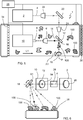
Figure 1 , shows, schematically, a first embodiment of a system for analysing the chemical composition of a target material according to the invention. -
Figure 2 , shows, schematically, a second embodiment of a system for analysing the chemical composition of a target material according to the invention. -
Figure 3 , shows, schematically, a third embodiment of a system for analysing the chemical composition of a target material according to the invention. -
Figure 4 , shows, schematically, a fourth embodiment of a system for analysing the chemical composition of a target material according to the invention. -
Figure 5 , shows, a top view of a fifth embodiment of a system for analysing the chemical composition of a target material according to the invention. -
Figure 6 , shows, a simplified front view of the embodiment offigure 5 . -
Figure 1 shows a first embodiment of thesystem 1 for analysing the chemical composition of atarget material 100 of the invention. Thetarget material 100 is preferably a metallic scrap part or parts placed on a static supportingsurface 26. - The
system 1 according to the invention comprises mainly following elements: alaser system 2, a scanner assembly, aspectral analyser 10 and finally control means 28, not shown in detail, responsible for controlling the operation of thelaser system 2, the scanner assembly and thespectral analyser 10. All these elements are arranged within ahousing 30 comprising aprotective window 32 through which laser light can be projected onto thetarget material 100 to be analysed. - The
laser system 2 comprises at least one laser device. This laser device provides alaser beam 4 of laser pulses within a short time interval which in the figures is indicated with arrows made from two converging segments. Preferably, the laser system uses a solid-state laser, like a neodymium-doped yttrium aluminium garnet, commonly known in the art as Nd:YAG laser. - The scanner assembly of system of the invention is configured to direct the
laser beam 4 coming from thelaser system 2 onto thetarget material 100. Thislaser beam 4 has an energy level that is high enough to produce luminous plasma by vaporising thetarget material 100 but lower as the systems known in the art. The light emitted by thetarget material 100 and the collecting path thereof is indicated in the figures with solid arrows. Furthermore, to produce luminous plasma is desirable to provide a plurality of pulses within a short time interval such that each of the pulses falls on thetarget material 100 to be analysed within a distance of less than few hundred micrometers. In a preferred embodiment of the invention up to 4 laser pulses may be directed on thetarget material 100, with an interpulse delay of 0.5 to 100 microseconds, using one or several triggerable Nd:YAG laser devices. As it will be apparent in other embodiments, it is also contemplated that thesystem 1 comprises a plurality of scanner assemblies. In embodiments where a plurality of scanner assemblies are employed to cover a surface area which is larger than what it would be possible with a single scanner assembly, the control system preferably triggers the firing of each laser system, such that one and only one laser fires as any one time, and such that the light from one, and one only scanner assembly, reaches the spectral analyser system at any one time. - The scanner assembly comprises first focusing
means 6 arranged downstream of thelaser system 2. The focusing means is, e.g. a focusing lens, causes thelaser beam 4 to converge in order to form a spot at a defined distance of the lens. Additionally, alight collector 8 is arranged downstream of the first focusingmeans 6. Thislight collector 8, which is preferably a single optical fibre, or a compact fibre bundle of optical fibres, collects the light emitted by the plasma passing first through the first focusingmeans 6 before reaching thelight collector 8. - The scanner assembly further comprises first
light redirecting means 12 arranged downstream of thelaser system 2. In order to achieve a more sensitive system having lower energy requirements, the firstlight redirecting means 12 are configured to let the laser light pass therethrough when the light falls on onefirst side 14 thereof and to redirect or deflect at least part of the light emitted by the surface on which the laser light falls on, when the returning light falls on asecond side 16 opposite to thefirst side 14. Particularly preferably the firstlight redirecting means 12 is one of the group of a perforated mirror, a semitransparent mirror or a dichroic mirror. Furthermore, as it is apparent fromfigure 1 , the firstlight redirecting means 12 is arranged between thelaser system 2 and the first focusingmeans 6. Thus, the firstlight redirecting means 12 gather the light emitted by the plasma, collinearly with thelaser beam 4 responsible of producing the luminous plasma on thetarget material 100 and redirect at least part of this light emitted by the plasma onto the first focusingmeans 6 and from here to thelight collector 8. - Finally, the
spectral analyser 10 is provided for receiving the light from thelight collector 8 and for isolating and measuring at least one selected emission band from the light emitted by the plasma and collected via thelight collector 8. - Preferably, the
spectral analyser 10 is in the form of a Rowland circle polychromator with detectors placed at one or more spectral regions of interest. Each of the detectors is preferably a multichannel photomultipler tube (PMT) arranged such that each of the PMT channels accumulates the light from a small spectral range, and where the totality of the multiple channels in each multichannel PMT cover a proportionally wider spectral range. In cases where the system contains a plurality of scanner assemblies, it is preferable that the optical fibres from each of the scanner assemblies are arranged to form a line at the entrance slit of the polychromator, such that a given emission wavelength emitted from each fibre, will fall on the same channel of a given PMT. PMT are advantageous in this respect, due to their tall photosensitive channels, allowing the same wavelength emanating from a plurality of optical fibres arranged in a line at the entrance slit of the spectral analyser to fall on the same channel of a given PMT. - As already explained, both the
laser system 2 and the spectral analyser are timely and operatively controlled by the control means 28, e.g. a computer or the like. In other words, the control means 28 includes the hardware and electronic components necessary not only for controlling but also to properly operating the other elements of the system. - Back to the invention, particularly thanks to the first light redirecting means, the light emitted by the plasma can be collinearly collected. This collinearity allows lower laser energy to be used, improves the sensitivity and clearly simplifies the construction of the system. In the system known in the art, in which several optical fibres arranged side by side along the scanner system to collect the light emitted by the plasma, an integration sphere is needed to collect the light before it being introduced in the spectral analyser.
- The system of
figure 1 is static, that is, neither thesystem 1 nor thetarget material 100 move relative to each other during operation and analysis. However, it is contemplated that one of both could move or event both elements could move during the analysis in order to measure different points of thetarget material 100. - Below, further embodiments of the invention are described sharing most of the technical features of the embodiment of
figure 1 . Therefore, in the next embodiments the described features are only those differing from the features of the embodiment offigure 1 . For all other common features, reference is made to the description of the previous paragraphs. - In the embodiment of
figure 2 , a part from all parts already described, thesystem 1 further comprises secondlight redirecting means 18 arranged downstream of the firstlight redirecting means 12. This secondlight redirecting means 18 is a reflecting surface such as a mirror, or any other reflecting surface made of a material able to redirect the laser beam and to withstand the heat generated by thelaser beam 4. Thanks to this element, the light emitted by the plasma is redirected or deflected onto the first focusingmeans 6 directly after being deflected by the second light redirectedmeans 18. - The embodiment of
figure 3 is also similar to the embodiment offigure 2 . However, in this case, the secondlight redirecting means 18 is arranged downstream of the firstlight redirecting means 12 differently to the previous embodiment. In this case, the element receiving first the light emitted by thetarget material 100 is the secondlight redirecting means 18 instead of the firstlight redirecting means 12. Therefore, thirdlight redirecting means 20 needs to be arranged between thelaser system 2 and the firstlight redirecting means 12. This provides also a compacter system. Again, this thirdlight redirecting means 20 is also a mirror or an equivalent reflecting surface as it was the case of the secondlight redirecting means 18. Therefore, as it is apparent fromfigure 3 , the laser beam first falls onto the thirdlight redirecting means 20 and it is deflected onto thefirst side 14 of the firstlight redirecting means 12 to pass therethrough and to fall onto the secondlight redirecting means 18. From there and once deflected, thelaser beam 4 exits thehousing 30 throughprotective window 32 and falls onto thetarget material 100 for producing luminous plasma. This emitted light is received by the secondlight redirecting means 18 and redirected onto thesecond side 16 of the firstlight redirecting means 12 to be redirected onto the focusingmeans 6 and afterwards being collected by the optical fibre to be analysed in thespectral analyser 10. - The embodiment of
figure 4 is based on the embodiment offigure 3 . However, in this case, thesystem 1 further comprises laser beam expanding means 22 arranged between thelaser system 2 and the thirdlight redirecting means 20 for expanding saidlaser beam 4 before it falls onto said thirdlight redirecting means 20. The laser beam expanding means 22 expands thelaser beam 4 to a wider diameter. This reduces the intensity of thelaser beam 4 incident on the subsequent optical components. Therefore, the likelihood of damage of the optical components is reduced. - Additionally the
system 1 offigure 4 further comprises second focusing means 24 arranged between the thirdlight redirecting means 20 and the firstlight redirecting means 12. This second focusingmeans 24 makes thelaser beam 4 converge to form a small spot which lies on or close to the surface of thetarget material 100. Therefore, a more efficient system is obtained, because again a lower laser intensity can be used to produce plasma on the surface of thetarget material 100. - Finally, the embodiment of
figures 5 and 6 is mainly based on the embodiment offigure 4 . Even if it is not depicted in this case, the laser system, the scanner assembly and the spectral analyser are also contained within a housing. - Differently to the previous embodiment, the system is provided to be arranged over the supporting
surface 26 for supporting saidtarget material 100 in order to analyse thetarget material 100 passing by below the scanner assembly. Therefore, in order to increase the performance of the system, the supportingsurface 26 and the scanner assembly are movable relative to each other. In particular, in this case, the supportingsurface 26 is a conveyor belt which moves along a longitudinal direction L at speeds up to 3 m/s. Alternatively the scanner assembly could also move longitudinally along the supportingsurface 26. - On the other hand, and differently to the embodiment of
figure 4 , in order for the system to increase the inspection speed, the secondlight redirecting means 18 is rotatably reciprocatingly mounted around an axis A1. This axis A1 is parallel to the longitudinal direction L and thus it allows scanning the complete width of the conveyor in a plane P perpendicular to the longitudinal direction L. To control the rotation of the second light redirecting means, a galvanometric control or a stepper motor can be applied. - Also, in this case, the laser beam expanding means 22 is also relevant in order to correctly scan the whole width of the supporting
surface 26. Thanks to the fact that the diameter of thelaser beam 4 can be modified the laser focus depth of field can be controlled such as to accommodate the variation in the laser focal point from the surface due to the scanning range, and also to accommodate a reasonable range of distance between the rotating mirror and the surface of the target material. - All the
system 1 offigures 4 and5 can be combined with adetection device 34, such as an array of inductive or capacitive sensors, arranged upstream of the scanner assembly. The system further comprises asorting device 36 arranged downstream of the scanner assembly. This sorting device can be, for example, a robot arm or a blowing device. - In this case, the control means 28 also centrally control the
detection device 34 and thesorting device 36. Thedetection device 34 allows for the determination of the position oftarget material 100 on the conveyor. Therefore, once the spectral analyser has determined if thetarget material 100 is to be selected or not, then thesorting device 36 downstream of the scanner assembly can decide and select where to place the corresponding sample. - It must also be pointed out, that generally, the light expanding means 22 and third
light redirecting means 20 are preferably optimized for the wavelength of thelaser beam 4. The optical properties of the firstlight redirecting means 12 and of the first focusing means and of thelight collector 8 are preferably optimized for the wavelengths of interest within the LIBS plasma. The optical properties of the secondlight redirecting means 18 and of theprotective window 32 are preferably optimized for both the wavelength of the laser beam and for wavelengths of interest contained in the LIBS plasma. - In some laser systems, it is preferable to maintain a near constant laser trigger frequency to achieve more stable thermal conditions within the laser, such that the laser produces more stable pulses. In such cases the second light redirecting means may be rotated to a dump zones, located at both sides of the
protective window 32 and with thelaser beam 4 directed towards one of the dump zones, one or more laser pulses may be fired to maintain thermal conditions within the laser, without giving rise to LIBS plasma during said shots. - The system of the present invention thus effectively analyses the chemical composition of target points on a surface based on the optical analysis of the laser-induced plasma produced at those target points.
- While the best mode for carrying out the invention has been described in detail, the skilled person will recognize various alternative designs and embodiments for putting the invention into practice and which can be based on the combination of the embodiments already described.
Claims (14)
- A system (1) for analysing the chemical composition of a target material (100) comprising:[a] a laser system (2) comprising at least one laser for providing a laser beam (4) of laser pulses,[b] at least one scanner assembly for directing said laser beam (4) onto said target material (100) such as to produce luminous plasma on said target material (100) and to collect the light emitted by said plasma, said scanner assembly comprising:[i] first focusing means (6), arranged downstream of said laser system (2), and[ii] a light collector (8) arranged downstream of said first focusing means (6) for collecting the light emitted by said plasma passing through said first focusing means (6), and[c] a spectral analyser (10) for receiving light from said light collector (8) for isolating and measuring at least one selected emission band from the light collected by said light collector (8),characterized in that said scanner assembly further comprises at least[d] first light redirecting means (12) arranged downstream of said laser system (2),[e] said first light redirecting means (12), being configured such as to let the light pass therethrough when the light falls on one first side (14) of said first light redirecting means (12) and to redirect at least part of the light when the light falls on a second side (16) opposite to said first side (14), and in that[f] said first light redirecting means (12) are arranged in said system (1)[i] to gather said light emitted by said plasma, collinearly with said laser beam directed onto said target material (100) and[ii] to redirect at least part of said light emitted by said plasma onto said first focusing means (6).
- The system of claim 1, characterized in that it further comprises second light redirecting means (18) arranged downstream of said first light redirecting means (12), for redirecting said light emitted by said plasma, onto said first focusing means (6) either directly or via said second side (16) of said first light redirecting means (12).
- The system of claim 2, characterized in that it further comprises third light redirecting means (20) arranged between said laser system (2) and said first light redirecting means (12) for redirecting said laser beam (4) onto said first side (14) of said first light redirecting means (12).
- The system of claim 3, characterized in that said second light redirecting means (18) is rotatably reciprocatingly mounted around an axis (A1).
- The system of any of claims 1 to 4, characterized in that said first light redirecting means (12) is one of the group of a perforated mirror, a semitransparent mirror or a dichroic mirror.
- The system of any of claims 2 to 5, characterized in that said second and third light redirecting means (18, 20) is a mirror.
- The system of any of claims 3 to 6, characterized in that it further comprises laser beam expanding means (22) arranged between said laser system (2) and said third light redirecting means (20) for expanding said laser beam (4) before it falls onto said third light redirecting means (20).
- The system of claim 7, characterized in that it further comprises second focusing means (24) arranged between said third light redirecting means (20) and said first light redirecting means (12).
- The system of any of claims 1 to 9, characterized in that it further comprises a supporting surface (26) for supporting said target material (100) and in that said supporting surface (26) and said scanner assembly are movable relative to each other.
- The system of claim 9 when depending on any of claims 4 to 8, characterized in that said supporting surface (26) is movable along a longitudinal direction (L).
- The system of claim 10, characterized in that said scanner assembly is arranged over said supporting surface (26) and in that said second light redirecting means (18) is rotatably reciprocatingly mounted around an axis (A1) parallel to said longitudinal direction such as to scan the width of said supporting surface in a plane (P) perpendicular to said longitudinal direction (L).
- The system of claim 10 or 11, characterized in that it further comprises an array of detection devices (34) arranged upstream of said scanner assembly and covering the width (W) of said supporting surface (26), said detection devices being a plurality of inductive or capacitive sensors.
- The system of claim 12, characterized in that said detection device is arranged below said supporting surface (26).
- A process for analysing the chemical composition of a target material (100) with a system according to any of the claims 1 to 13, the process comprising the steps of:[a] emitting a laser beam (4) on to the surface of said target material (100), such as to produce luminous plasma on said target material (100) and[b] collecting the light emitted by said plasma, and[c] isolating and measuring at least one selected emission band contained in the light emitted by said plasma,characterized in that[d] said light emitted by said plasma is collected collinearly with at least the section of the laser beam falling on said target material (100) for producing the luminous plasma and redirected onto the aperture of the light collector (8) of the system.
Priority Applications (1)
| Application Number | Priority Date | Filing Date | Title |
|---|---|---|---|
| EP16382678.7A EP3343205A1 (en) | 2016-12-30 | 2016-12-30 | A system for analysing the chemical composition of a target material and corresponding process |
Applications Claiming Priority (1)
| Application Number | Priority Date | Filing Date | Title |
|---|---|---|---|
| EP16382678.7A EP3343205A1 (en) | 2016-12-30 | 2016-12-30 | A system for analysing the chemical composition of a target material and corresponding process |
Publications (1)
| Publication Number | Publication Date |
|---|---|
| EP3343205A1 true EP3343205A1 (en) | 2018-07-04 |
Family
ID=57796147
Family Applications (1)
| Application Number | Title | Priority Date | Filing Date |
|---|---|---|---|
| EP16382678.7A Withdrawn EP3343205A1 (en) | 2016-12-30 | 2016-12-30 | A system for analysing the chemical composition of a target material and corresponding process |
Country Status (1)
| Country | Link |
|---|---|
| EP (1) | EP3343205A1 (en) |
Cited By (1)
| Publication number | Priority date | Publication date | Assignee | Title |
|---|---|---|---|---|
| EP3650842A1 (en) * | 2018-11-12 | 2020-05-13 | Hitachi High-Tech Analytical Science Finland Oy | A light collection arrangement for optical emission spectroscopy |
Citations (7)
| Publication number | Priority date | Publication date | Assignee | Title |
|---|---|---|---|---|
| DE4004627A1 (en) * | 1990-02-15 | 1991-02-28 | Krupp Gmbh | Automatically testing polymeric material - focussing pulsating laser beam via revolving mirror on to successive points on moving material and analysing radiation spectrum produced |
| DE4426490C2 (en) * | 1993-07-27 | 1996-10-24 | Hohla Kristian | Method for analyzing metallic parts that are moved by a transport unit and device for carrying out the method |
| US20020163735A1 (en) * | 2000-01-11 | 2002-11-07 | Gunther Detlef | Radially homogeneous high energy density UV sample ablating laser radiation in "pure" solid to gas sample preparation , for analysis by ICP-MS and ICP-OES |
| US20030132142A1 (en) | 1996-02-16 | 2003-07-17 | Huron Valley Steel Corporation | Metal scrap sorting system |
| WO2013020712A1 (en) * | 2011-08-10 | 2013-02-14 | ProASSORT GmbH | Metal scrap sorting |
| WO2015200111A1 (en) * | 2014-06-23 | 2015-12-30 | Tsi, Inc. | Rapid material analysis using libs spectroscopy |
| WO2017037680A1 (en) * | 2015-09-02 | 2017-03-09 | Elemission Inc. | Method and system for analysis of samples using laser induced breakdown spectroscopy |
-
2016
- 2016-12-30 EP EP16382678.7A patent/EP3343205A1/en not_active Withdrawn
Patent Citations (7)
| Publication number | Priority date | Publication date | Assignee | Title |
|---|---|---|---|---|
| DE4004627A1 (en) * | 1990-02-15 | 1991-02-28 | Krupp Gmbh | Automatically testing polymeric material - focussing pulsating laser beam via revolving mirror on to successive points on moving material and analysing radiation spectrum produced |
| DE4426490C2 (en) * | 1993-07-27 | 1996-10-24 | Hohla Kristian | Method for analyzing metallic parts that are moved by a transport unit and device for carrying out the method |
| US20030132142A1 (en) | 1996-02-16 | 2003-07-17 | Huron Valley Steel Corporation | Metal scrap sorting system |
| US20020163735A1 (en) * | 2000-01-11 | 2002-11-07 | Gunther Detlef | Radially homogeneous high energy density UV sample ablating laser radiation in "pure" solid to gas sample preparation , for analysis by ICP-MS and ICP-OES |
| WO2013020712A1 (en) * | 2011-08-10 | 2013-02-14 | ProASSORT GmbH | Metal scrap sorting |
| WO2015200111A1 (en) * | 2014-06-23 | 2015-12-30 | Tsi, Inc. | Rapid material analysis using libs spectroscopy |
| WO2017037680A1 (en) * | 2015-09-02 | 2017-03-09 | Elemission Inc. | Method and system for analysis of samples using laser induced breakdown spectroscopy |
Cited By (2)
| Publication number | Priority date | Publication date | Assignee | Title |
|---|---|---|---|---|
| EP3650842A1 (en) * | 2018-11-12 | 2020-05-13 | Hitachi High-Tech Analytical Science Finland Oy | A light collection arrangement for optical emission spectroscopy |
| US10801888B2 (en) | 2018-11-12 | 2020-10-13 | Hitachi High-Tech Analytical Science Finland Oy | Light collection arrangement for optical emission spectroscopy |
Similar Documents
| Publication | Publication Date | Title |
|---|---|---|
| US6795179B2 (en) | Metal scrap sorting system | |
| AU2012265822B2 (en) | Method and apparatus for quantitative analysis of samples by laser induced plasma (LIP) | |
| US7233643B2 (en) | Measurement apparatus and method for determining the material composition of a sample by combined X-ray fluorescence analysis and laser-induced breakdown spectroscopy | |
| CN104374763B (en) | Adjustable reheating double pulse laser-induced breakdown spectroscopy device | |
| CN107107122A (en) | Analyzed using the rapid mass of LIBS spectrum | |
| US6069695A (en) | Process and arrangement for laser-induced spectral analysis | |
| AU2012265822A1 (en) | Method and apparatus for quantitative analysis of samples by laser induced plasma (LIP) | |
| US10295408B2 (en) | Raman spectroscopy system | |
| AU2019264883B2 (en) | Hybrid laser-induced breakdown spectroscopy system | |
| Davies et al. | Remote in situ analytical spectroscopy and its applications in the nuclear industry | |
| DE102013008774B3 (en) | Analysis device installed in laser processing machine for analyzing laser radiation, has beam sensor that analyzes laser radiation in main beam path, and optical devices that analyzes respective analysis beam aligned on beam sensor | |
| US11945002B2 (en) | Automatic metal sorting system and method using laser induced breakdown spectroscopy | |
| EP1416265B1 (en) | Scanning system for use in a metal scrap sorting system | |
| EP3343205A1 (en) | A system for analysing the chemical composition of a target material and corresponding process | |
| US20010055113A1 (en) | Spectral analysis system with moving objective lens | |
| JP2005140529A (en) | Apparatus and method for analyzing element | |
| Vadillo et al. | Space and time-resolved laser-induced breakdown spectroscopy using charge-coupled device detection | |
| EP3650842B1 (en) | A light collection arrangement for optical emission spectroscopy | |
| KR20060025402A (en) | Optical system for multi-channel sample analyzer and analyzer employing the same | |
| KR102281696B1 (en) | System for automatic sort of waste metal based on libs | |
| US10732117B2 (en) | Device for analyzing the material composition of an object via plasma spectrum analysis having a long pass filter | |
| US10234396B1 (en) | Device for analyzing the material composition of a sample via plasma spectrum analysis | |
| Wang et al. | Spectral stability improvement through wide fields of view collection optics in laser-induced breakdown spectroscopy applications | |
| CN110596077A (en) | Weak light source Rowland grating linear array CCD/CMOS detector light splitting system and method | |
| DE19932069A1 (en) | Device for laser-induced emission spectrometry permits the scanning of a sample surface through a laser beam used in a definite manner. |
Legal Events
| Date | Code | Title | Description |
|---|---|---|---|
| PUAI | Public reference made under article 153(3) epc to a published international application that has entered the european phase |
Free format text: ORIGINAL CODE: 0009012 |
|
| STAA | Information on the status of an ep patent application or granted ep patent |
Free format text: STATUS: REQUEST FOR EXAMINATION WAS MADE |
|
| 17P | Request for examination filed |
Effective date: 20161230 |
|
| AK | Designated contracting states |
Kind code of ref document: A1 Designated state(s): AL AT BE BG CH CY CZ DE DK EE ES FI FR GB GR HR HU IE IS IT LI LT LU LV MC MK MT NL NO PL PT RO RS SE SI SK SM TR |
|
| AX | Request for extension of the european patent |
Extension state: BA ME |
|
| STAA | Information on the status of an ep patent application or granted ep patent |
Free format text: STATUS: EXAMINATION IS IN PROGRESS |
|
| 17Q | First examination report despatched |
Effective date: 20190320 |
|
| STAA | Information on the status of an ep patent application or granted ep patent |
Free format text: STATUS: THE APPLICATION IS DEEMED TO BE WITHDRAWN |
|
| 18D | Application deemed to be withdrawn |
Effective date: 20191001 |