EP3343077B1 - Agencement de robinet à pression constante à clapet et son utilisation - Google Patents
Agencement de robinet à pression constante à clapet et son utilisation Download PDFInfo
- Publication number
- EP3343077B1 EP3343077B1 EP16207118.7A EP16207118A EP3343077B1 EP 3343077 B1 EP3343077 B1 EP 3343077B1 EP 16207118 A EP16207118 A EP 16207118A EP 3343077 B1 EP3343077 B1 EP 3343077B1
- Authority
- EP
- European Patent Office
- Prior art keywords
- flap
- back pressure
- locking pin
- valve arrangement
- locking
- Prior art date
- Legal status (The legal status is an assumption and is not a legal conclusion. Google has not performed a legal analysis and makes no representation as to the accuracy of the status listed.)
- Active
Links
- 238000007789 sealing Methods 0.000 claims description 32
- 239000003351 stiffener Substances 0.000 claims description 19
- 239000000428 dust Substances 0.000 claims description 8
- 239000000725 suspension Substances 0.000 claims description 3
- 101001017827 Mus musculus Leucine-rich repeat flightless-interacting protein 1 Proteins 0.000 description 39
- 238000004880 explosion Methods 0.000 description 8
- 239000002245 particle Substances 0.000 description 4
- 230000005484 gravity Effects 0.000 description 3
- 238000009434 installation Methods 0.000 description 3
- 238000011144 upstream manufacturing Methods 0.000 description 3
- 230000006835 compression Effects 0.000 description 2
- 238000007906 compression Methods 0.000 description 2
- 230000000694 effects Effects 0.000 description 2
- 238000007689 inspection Methods 0.000 description 2
- 239000000463 material Substances 0.000 description 2
- 230000004308 accommodation Effects 0.000 description 1
- 230000001154 acute effect Effects 0.000 description 1
- 230000002411 adverse Effects 0.000 description 1
- 230000001419 dependent effect Effects 0.000 description 1
- 239000002360 explosive Substances 0.000 description 1
- 239000012530 fluid Substances 0.000 description 1
- 238000002955 isolation Methods 0.000 description 1
- 238000012423 maintenance Methods 0.000 description 1
- 239000002184 metal Substances 0.000 description 1
- 238000000034 method Methods 0.000 description 1
- 239000011236 particulate material Substances 0.000 description 1
- 230000001902 propagating effect Effects 0.000 description 1
Images


Classifications
-
- A—HUMAN NECESSITIES
- A62—LIFE-SAVING; FIRE-FIGHTING
- A62C—FIRE-FIGHTING
- A62C2/00—Fire prevention or containment
- A62C2/06—Physical fire-barriers
- A62C2/12—Hinged dampers
-
- F—MECHANICAL ENGINEERING; LIGHTING; HEATING; WEAPONS; BLASTING
- F16—ENGINEERING ELEMENTS AND UNITS; GENERAL MEASURES FOR PRODUCING AND MAINTAINING EFFECTIVE FUNCTIONING OF MACHINES OR INSTALLATIONS; THERMAL INSULATION IN GENERAL
- F16K—VALVES; TAPS; COCKS; ACTUATING-FLOATS; DEVICES FOR VENTING OR AERATING
- F16K15/00—Check valves
- F16K15/02—Check valves with guided rigid valve members
- F16K15/03—Check valves with guided rigid valve members with a hinged closure member or with a pivoted closure member
-
- A—HUMAN NECESSITIES
- A62—LIFE-SAVING; FIRE-FIGHTING
- A62C—FIRE-FIGHTING
- A62C4/00—Flame traps allowing passage of gas but not of flame or explosion wave
- A62C4/02—Flame traps allowing passage of gas but not of flame or explosion wave in gas-pipes
-
- F—MECHANICAL ENGINEERING; LIGHTING; HEATING; WEAPONS; BLASTING
- F16—ENGINEERING ELEMENTS AND UNITS; GENERAL MEASURES FOR PRODUCING AND MAINTAINING EFFECTIVE FUNCTIONING OF MACHINES OR INSTALLATIONS; THERMAL INSULATION IN GENERAL
- F16K—VALVES; TAPS; COCKS; ACTUATING-FLOATS; DEVICES FOR VENTING OR AERATING
- F16K17/00—Safety valves; Equalising valves, e.g. pressure relief valves
- F16K17/02—Safety valves; Equalising valves, e.g. pressure relief valves opening on surplus pressure on one side; closing on insufficient pressure on one side
- F16K17/164—Safety valves; Equalising valves, e.g. pressure relief valves opening on surplus pressure on one side; closing on insufficient pressure on one side and remaining closed after return of the normal pressure
-
- F—MECHANICAL ENGINEERING; LIGHTING; HEATING; WEAPONS; BLASTING
- F16—ENGINEERING ELEMENTS AND UNITS; GENERAL MEASURES FOR PRODUCING AND MAINTAINING EFFECTIVE FUNCTIONING OF MACHINES OR INSTALLATIONS; THERMAL INSULATION IN GENERAL
- F16K—VALVES; TAPS; COCKS; ACTUATING-FLOATS; DEVICES FOR VENTING OR AERATING
- F16K17/00—Safety valves; Equalising valves, e.g. pressure relief valves
- F16K17/20—Excess-flow valves
- F16K17/34—Excess-flow valves in which the flow-energy of the flowing medium actuates the closing mechanism
-
- F—MECHANICAL ENGINEERING; LIGHTING; HEATING; WEAPONS; BLASTING
- F16—ENGINEERING ELEMENTS AND UNITS; GENERAL MEASURES FOR PRODUCING AND MAINTAINING EFFECTIVE FUNCTIONING OF MACHINES OR INSTALLATIONS; THERMAL INSULATION IN GENERAL
- F16K—VALVES; TAPS; COCKS; ACTUATING-FLOATS; DEVICES FOR VENTING OR AERATING
- F16K17/00—Safety valves; Equalising valves, e.g. pressure relief valves
- F16K17/36—Safety valves; Equalising valves, e.g. pressure relief valves actuated in consequence of extraneous circumstances, e.g. shock, change of position
- F16K17/363—Safety valves; Equalising valves, e.g. pressure relief valves actuated in consequence of extraneous circumstances, e.g. shock, change of position the closure members being rotatable or pivoting
-
- B—PERFORMING OPERATIONS; TRANSPORTING
- B01—PHYSICAL OR CHEMICAL PROCESSES OR APPARATUS IN GENERAL
- B01D—SEPARATION
- B01D46/00—Filters or filtering processes specially modified for separating dispersed particles from gases or vapours
- B01D46/0084—Filters or filtering processes specially modified for separating dispersed particles from gases or vapours provided with safety means
- B01D46/0091—Including arrangements for environmental or personal protection
- B01D46/0093—Including arrangements for environmental or personal protection against fire or explosion
Definitions
- the present invention relates to a back pressure flap valve arrangement and the use of such back pressure flap valve arrangement in a ducting intended to conduct a dust or particle laden gas flow.
- the containers may be provided with an air filter system.
- the material may be supplied to the containers by means of a gaseous flow through a ducting.
- the dust may be explosive.
- an ignition may occur in the container due to ignition sources transported to the container with the airflow or due to ignition sources inside the container. Such ignition may result in devastating effects both on personnel, buildings, and the equipment, since the ignition may cause an explosion with a pressure wave and a flame front which propagates along the ducting opposite to the normal airflow direction.
- the back pressure flap valve arrangement typically comprises a flap which is arranged to act as a check valve which may close off the ducting.
- the flap is maintained in an open position by the dust or particle laden air stream flowing along the ducting.
- the flap is arranged to close the passage through the ducting by the pressure wave acting on the flap.
- a locking mechanism is known from e.g. DE 202009011668U1 .
- the loads imposed by an explosion may be very high, whereby the flap and its locking mechanism must be designed to meet such loads. Still, the design must not interfere with the normal functionality of the ducting and the flap.
- US2012/0048399 discloses a back pressure flap valve arrangement comprising a housing having an inlet opening and an outlet opening adapted for connection of the housing to a ducting, and at least one side wall extending along a flow direction through the housing from the inlet opening to the outlet opening, the arrangement further comprising a flap which is pivotably hinged about a shaft thereby being movable between an open position and a closed position, said shaft extending transverse the flow direction, wherein the arrangement further comprises at least one locking device being fixedly mounted to the side wall and comprising a locking pin, said locking pin being movable between a retracted position and a locking position, and being biased towards said locking position.
- the back pressure flap valve arrangement should not allow any rebound of the flap in case of such pressure wave.
- the invention refers to a back pressure flap valve arrangement
- a housing having an inlet opening and an outlet opening adapted for connection of the housing to a ducting, and at least one side wall extending along a flow direction through the housing from the inlet opening to the outlet opening, the arrangement further comprising a flap which is pivotably hinged about a shaft thereby being movable between an open position and a closed position, said shaft extending transverse the flow direction.
- the arrangement further comprises at least one locking device being fixedly mounted to the side wall and comprising a locking pin and a stopping member, said locking pin being movable between a retracted position and a locking position, and being biased towards said locking position, and the stopping member being movable from a stop position in which the stopping member is adapted to hold the locking pin in its retracted position, to a release position by the flap acting on the stopping member in case of a back pressure, thereby allowing the locking pin to move into the locking position in which the locking pin maintains the flap in the closed position.
- the inventive back pressure flap valve arrangement a solution is provided that allows an instant and complete closing-off of the ducting in case a back pressure should occur.
- the locking device is activated by the flap, provided the kinetic energy caused by a back pressure is high enough to overcome the releasing force required to release the engagement between the stopping member and the locking pin.
- the required releasing force is determined by a combination of friction between the locking pin and the stopping member and also the biasing force of the locking pin.
- the flap In the released condition, the flap is held and maintained in a position between the closed-off inlet opening and the locking pin.
- the closing-off is maintained until a resetting is actively made.
- the closing-off is not the result of any kinetic energy being absorbed by components deforming but rather a controlled mechanical interlocking between mutually movable parts. Accordingly, after a release, the locking device may be reset and reused.
- the ducting may comprise a flexible sealing arranged in a position between the inlet opening and the flap, which flexible sealing must be at least partly compressed by the pivoting of the flap for the flap to be able to act on the stopping member.
- a radial gap may be formed between the flexible sealing and the inlet opening of the ducting.
- the radial gap allows accommodation of the deformation of the flexible sealing that results when the same is compressed by the flap. Thereby the flexible sealing will be prevented from being cut by the flap compressing it against the edge of the inlet duct.
- the stopping member may be movable from the stop position to the release position by the stopping member being arranged to pivot around a pivot, said pivot having a longitudinal extension essentially in parallel with the surface extension of the flap as seen in a position when the flap has pivoted to its closed position in case of a back pressure.
- the stopping member may comprise a stop face having a surface extension essentially in parallel with the surface extension of the flap as seen in a position when the flap has pivoted to its closed position, and wherein the flap, in case of a back pressure, is arranged to act on said stop face thereby moving the stopping member from its stop position to its release position.
- the stopping member may comprise a shoulder arranged to engage the locking pin when the locking pin is held in its retracted position.
- the shoulder preferably comprises an abutment surface extending transverse the longitudinal axis of the locking pin.
- the flap may comprise a stiffener, and the locking pin may be adapted to abut said stiffener in a condition when the flap has been pivoted to its closed position.
- the stiffener reduces the risk of the flap being deformed, e.g. by being crooked by a back pressure. Even though the flap, which typically is made of sheet metal, should be crooked due to the high forces caused by a back pressure, it is most likely that the stiffener as such will remain its geometry. Thus, by arranging the locking pin to abut and engage the stiffener, the risk of a failed locking effect is substantially reduced.
- the locking device may further comprise a base plate via which the locking device is fixedly mounted to a side wall of the housing, wherein the locking pin is arranged to extend from a first side of the base plate, via a through hole in the base plate, to a second side of the base plate, and wherein the locking pin is biased towards the locking position by an elastic member being supported by the portion of the locking pin extending on the second side of the base plate.
- the locking pin may be arranged to be set from the locking position to the retracted position by pulling the locking pin, thereby overcoming the biasing, and while pulling the locking pin, moving the stopping member from its release position to its stop position.
- the locking device may further comprise a resetting member, said resetting member comprising a resetting pin extending from the first side of the base plate, via a through hole in the base plate, to the second side of the base plate, and whereby the stopping member is arranged to be moved from its release position to its stop position by pushing the resetting member towards the stopping member.
- a resetting member comprising a resetting pin extending from the first side of the base plate, via a through hole in the base plate, to the second side of the base plate, and whereby the stopping member is arranged to be moved from its release position to its stop position by pushing the resetting member towards the stopping member.
- the resetting member may be biased towards the first side of the base plate.
- the shaft may be rotatably suspended in two opposing side walls of the housing, and the suspension may be made via two long holes arranged in the respective side walls.
- the long holes By the long holes, the installation is facilitated by allowing an adjustment of the distance between the flap and the duct opening as seen in the longitudinal extension of the ducting.
- the flap may be further pivotably hinged along a pivot extending in parallel with the shaft, said pivot being arranged to extend across the surface extension of the flap.
- the invention relates to the use of a back pressure flap valve arrangement with the features as given above in a ducting intended to conduct a dust or particulate laden gas flow.
- a back pressure flap valve arrangement 100 is disclosed as arranged in a ducting 200.
- the back pressure flap valve arrangement 100 will in the following be referred to as "the arrangement".
- the flap 1 of the flap valve 2 is arranged to pivot between a closed position, see Fig. 1 , in which the flap 1 closes-off the ducting 200, and an open position, see Fig. 2 in which a flow is allowed through the ducting 200.
- the ducting 200 comprises starting from the right side a first duct portion 201 forming an inlet opening 202.
- the inlet opening 202 is chamfered and forms a downwardly directed acute angle ⁇ of 3-40° in view of a vertical plane and more preferred an angle of 10-30°.
- the first duct portion 201 extends into a chamber 203.
- the chamber 203 is at least partly formed by the arrangement 100 to be described in detail below.
- the chamber 203 has a longitudinal extension as seen along the longitudinal extension of the ducting 200 to allow pivoting of the flap 1 between the open and the closed position.
- a second duct portion 204 is mounted to the chamber 203.
- the second duct portion 204 forms an outlet opening 205.
- the arrangement 100 is connected to the ducting 200 in a position before, i.e. upstream, a container (not disclosed) such that normal process flow is arranged to pass from the inlet opening 202 through the flap valve 2 before it reaches the container.
- the container is adapted to receive a dust or particle laden fluid flow to be fed along the ducting 200 from the inlet opening 202 to the outlet opening 205.
- a flexible sealing 206 is arranged to encircle the inlet opening 202 of the ducting 200.
- the flexible sealing 206 is arranged to extend past the free edge 207 of the inlet opening 202.
- the flexible sealing 206 is arranged with a radial gap 208 between the flexible sealing 206 and the inlet opening 202.
- the flap 1 is allowed to pivot between the open position of Fig. 2 and the closed position of Fig. 1 depending on the operation of fans (not disclosed) that are included in the ducting 200.
- the fans generate an air-flow which is sufficiently strong to overcome the gravity and thereby pivot the flap 1 to its open position.
- the flap 1 will pivot by gravity to its closed position in which the flap 1 loosely abuts the flexible sealing 206 encircling the inlet opening 202 and hence temporarily closes off the inlet opening 202.
- the flexible sealing 206 preferably exhibits an inherent stiffness that can resist the weight of the flap without any substantial deformation.
- the flexible sealing 206 is dimensioned to require a deformation of at least 6 mm as seen in the longitudinal direction of the ducting in order for the flap 1 to come in contact with and operate the locking device 10.
- the required deformation is the result of a combination of parameters such as geometry and material properties of the flexible sealing and weight and dimensions of the flap.
- the exemplified deformation of 6 mm should be seen as a non-limiting example allowing the locking device 10 to be activated both during operation with airflow and during a fan stand-still.
- the arrangement 100 should be set to a locking position in which the flap valve 2 immediately is set to close-off the inlet opening 202 and further is maintained in such position by a locking device 10 to be described below. As the flap 1 is moved to the locked position, the flexible sealing 206 is compressed.
- the deformation of the flexible sealing 206 will be accommodated by the radial gap 208 that is arranged between the flexible sealing 206 and the inlet duct 202.
- the flexible sealing is protected from being cut by the flap compressing it against the edge of the inlet duct 202.
- the locking device 10 may be activated both during operation with airflow and during a fan stand-still since a pressure wave generated during a pack pressure may be strong enough to compress the flexible sealing 206 to such extent that the flap 1 may come in contact with and operate the locking device 10.
- the arrangement 100 comprises a housing 101 having an inlet opening 102 and an outlet opening 103.
- the inlet and outlet openings 102, 103 are adapted for connection of the housing 101 to the ducting 200.
- the housing 101 comprises two opposing side walls 104, one bottom wall 105 and one top wall 106.
- the housing 101 is encircled by a flange 107 allowing the housing 101 to be mounted to the ducting 200.
- the arrangement 100 comprises the flap valve 2 which as such comprises the flap 1.
- the flap 1 is formed by a thin walled, essentially flat plate 4 having a surface extension that exceeds the cross sectional area delimited by the flexible sealing 206.
- the flap 1 comprises stiffeners 3.
- the stiffeners 3 are arranged on the surface intended to face away from the inlet opening 202.
- the stiffeners 3 are formed by U-shaped profiles mounted to the flap 1. It is to be understood that other geometries are possible.
- the mounting is preferably made by bolting, thereby allowing easy replacement of the flap 1.
- the stiffeners 3 can e.g. be welded to the flap 1. It is to be understood that the stiffeners 3 as such may be omitted. In the latter case the plate 4 making up the flap 1 should have a thickness sufficient to withstand a back pressure.
- the flap 1 is pivotably hinged about a shaft 5.
- the shaft 5 is pivotably suspended in the two opposing side walls 104 of the housing 101 and extends transverse the flow direction through the ducting 200.
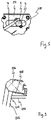
- the suspension of the shaft 5 is made by each side wall 104 comprising a long hole 108, see also Fig. 5 , into which the free ends of the shaft 5 are received.
- the shaft 5 is movably received inside and along said long holes 108 in order to account for dimensional tolerances regarding the position of the inlet opening 202 of the first duct 201 in view of the arrangement 100. As a proper position has been found during installation of the arrangement 100, the position is fixated. In the fixed condition, the shaft 5 together with the flap 1 may pivot around the longitudinal extension of the shaft 5 by means of bearings (not disclosed). The shaft 5 thereby constitutes a first pivot 6.
- the flap 1 is fixed to the shaft 5 via two struts 7.
- a first end 7a of the respective strut 7 is fixedly mounted to the shaft 5 and hence to the first pivot 6.
- the second end 7b of the respective strut 7 projecting away from the shaft 5 is pivotably mounted to the flap 1 via one of the stiffeners 3, thereby forming a second pivot 8.
- the second pivot 8 is formed by the second end of the strut 7b being interconnected to the stiffener 3 by a bolt extending between the two opposing legs of the U-formed stiffener 3.
- the flap 1 being pivotably hinged around the two pivots 6, 8 the arrangement 100 will be less sensitive to any misalignments and tolerances between the position of the arrangement 100 in view of the inlet opening 202 to be closed-off by the flap 1.
- the flap 1 is indirectly connected to the shaft 5 via the struts 7. Should the flap 1 be deformed during a back pressure to such extent that it needs to be replaced, the flap 1 may be dismounted from the struts 7, without the need of changing the position of the shaft 5 in view of the respective long holes 108.
- the disclosed arrangement 100 comprises four locking devices 10 - two locking devices 10 on each exterior side wall 104 of the housing 101.
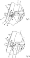
- the locking devices 10 are aligned with the longitudinal extension of two stiffeners 3. Now turning to Figs. 6a and 6b , the locking device 10 is disclosed.
- the locking device 10 comprises a base plate 11, a stopping member 12, a guide member 13, a locking pin 14 and a resetting member 15.
- the base plate 11 has a first side 16 adapted to face away from the housing 101 and a second side 17 adapted to face the housing 101.
- the base plate 11 has a rectangular form. It is to be understood that other geometries are possible with remained function.
- the base plate 11 comprises four through long holes 18 constituting mounting holes to be used when fixating the locking device 10 to the exterior side wall 104 of the housing 101. The long holes 18 facilitate adjustment of the position of the locking device 10 in view of the flap 1 of the arrangement 100 before fixation.
- the guide member 13 and the stopping member 12 are arranged on the second side 17 of the base plate 11.
- the guide member 13 is fixedly mounted to the base plate 11 and comprises a body having a through hole 19 extending perpendicular to the extension plane of the base plate 11.
- the through hole 19 is adapted to receive and guide a portion of the locking pin 14 to be discussed below.
- the stopping member 12 is formed as a body comprising on a first side thereof two legs 20, a stop face 21 and a shoulder 22 and on a second, opposite side thereof, a resetting surface 23.
- the two legs 20 project essentially perpendicular to the stop face 21.
- Each leg 20 comprises a through hole 24 extending essentially in parallel with the extension plane of the base plate 11.
- the stop face 21 is an essentially flat surface.
- the shoulder 22 projects from the stop face 21 and comprises an abutment surface 25 extending essentially in parallel with the extension of the two legs 20.
- the stopping member 12 is pivotably mounted to the guide member 13 by means of two bolts extending through the holes in the legs 20 and into the guide member 13.
- the bolts form a pivot allowing the stopping member 12 to be pivoted in view of the guide member 13 between a stop position and a release position.
- the abutment surface 25 of the shoulder 22 is arranged to extend substantially perpendicular to the longitudinal center axis of the through hole 19 of the guide member 13.
- the resetting surface 23 of the stopping member 12 is formed as a beveled surface facing the base plate 11. The resetting surface 23 is arranged to interact with the resetting member 15 to be described below.
- the locking device 10 comprises a locking pin 14.
- the locking pin 14 is arranged to extend from the first side 16 of the base plate 11, via a through hole 26 therein, to the second side 17 of the base plate 11.
- a first end 27 of the locking pin 14, i.e. the end facing away from the first side 16 of the base plate 11 comprises a hole (not shown) extending in the longitudinal direction of the locking pin 14.
- the hole receives a screw 28 with a head 29.
- An elastic member 30, in the disclosed embodiment in the form of a coil spring, is received in the interspace between the first end 27 of the locking pin 14 and the head 29 of the screw 28.
- the first end 27 of the locking pin 14 and the elastic member 30 are encapsulated inside a protecting tube 31.
- the end projecting from the second side 17 of the base plate 11 is arranged to abut the shoulder 22 of the stopping member 12 in a condition when the stopping member 12 is set to its stop position.
- At least a portion of the locking pin 14 that projects on the second side 17 of the base plate 11 is guided by the through hole 19 in the guide member 13.
- the locking pin 14 is movable between a locking position and a retracted position.
- the locking pin 14 is biased towards the locking position by the elastic member 30.
- the locking device 10 further comprises a resetting member 15.
- the resetting member 15 is arranged on the first side 16 of the base plate 11.
- the resetting member 15 comprises a resetting pin 33 that extends from the first side 16 of the base plate 11, via a through hole 34 therein, to the second side 17 of the base plate 11.
- a first end 35 of the resetting pin 33 that faces away from the first side 16 of the base plate 11 is mounted to an anvil 36.
- An elastic member 37 in the form of a coil spring is arranged to encircle the resetting pin 33. The elastic member 37 is biased between the anvil 36 and the base plate 11, in a direction away from the first side 16 of the base plate 11.
- the resetting pin 33 has a longitudinal extension that allows the resetting pin 33, when pushed in a direction towards the base plate 11 to engage the resetting surface 23 of the stopping member 12. Thereby the stopping member 12 may be moved by pivoting from its release position to its stop position.
- FIG. 7a a portion of the flap 1 with its stiffeners 3 is disclosed. This position represents a momentary position just before releasing of the locking device 10 due to a back pressure, i.e. the flap 1 has managed to compress the flexible sealing (not shown in Figs 7a and 7b ) to such extent that the edge of the flap 1 has come into contact with and abuts the stop face 21 of the stopping member 12. Accordingly, the locking device 10 as such is in a position, immediately before being released.
- the locking pin 14 In this momentary position the locking pin 14 is biased towards its locking position and the stopping member 12 has been pivoted to its stop position. Also, in this position, the locking pin 14 is biased by the elastic member 30 (not shown in Fig. 7a ) so that the second end 32 of the locking pin 14 abuts the shoulder 22 of the stopping member 12.
- the flap 1 will pivot further and hit the stop face 21 with such kinetic energy that the dimensioned releasing force required to release the locking mechanism is overcome.
- the required releasing force is determined by a combination of friction between the locking pin 14 and the abutment surface 25 of the shoulder 22 of the stopping member 12 and also the biasing force of the locking pin 14.
- the locking device 10 is disclosed in its released position.
- the kinetic energy of the flap 1 has caused the stopping member 12 to pivot from its stop position to its release position, which is turn has allowed the locking pin 14, as a result of its biasing, to move from its retracted position to its locked position.
- the remaining kinetic energy of the pivoting of the flap 1 is absorbed by the flexible sealing (not shown in Figs. 7a and 7b ) which is further compressed.
- the flap 1 has reached a stand-still position in which it is held and maintained in a closed and locked position between the closed-off inlet opening and the projecting locking pin 14.
- the locking device 10 Since the locking device 10 is arranged aligned with a stiffener 3 on the flap 1, the projecting portion of the locking pin 14 will engage either the stiffener 3 or the plate 4 making up the flap 1. The closing-off of the inlet opening is maintained until a resetting of the locking device 10 is actively made by an operator.
- an operator pulls the locking pin 14 in a direction away from the housing 101.
- the compression of the flexible sealing will be released, whereby the flap 1 will be forced by the recovering of the flexible sealing 206 to pivot away from the inlet opening.
- a gap is formed between the flap 1 and the inlet opening.
- the operator may release the pulling of the locking pin 14, whereby the locking pin 14, due to its biasing, will return to its locking position in which it engages the abutment surface 25 of the shoulder 22. Thereby, the locking device 10 has been reset and the arrangement 100 and the ducting 200 is ready to be used anew.
- the ducting 200 and the arrangement 100 with its components must be inspected after a reset to make sure that all components are in a proper condition without any undue deformations.
- the chamber of the ducting 200 may comprise an inspection door.
- the flap 1 has been disclosed as being fixed to the shaft 5 via two struts 7. It is to be understood that the number of struts 7 may differ.
- the disclosed arrangement 100 comprises four locking devices 10, i.e. two locking devices 10 on each side wall 104. It is to be understood that the number of locking devices 10 may differ depending of the overall size of the arrangement.
- the arrangement 100 should have at least one locking device 10.
- the arrangement may be provided as an insert to be mounted adjacent a duct opening in a ducting.
- the arrangement can be provided as an off-the shelf product ready to be installed in a ducting. Thereby the installation time may be reduced, and also maintenance or replacement in case the arrangement or parts thereof should have been damaged due to a back pressure.
Landscapes
- Engineering & Computer Science (AREA)
- General Engineering & Computer Science (AREA)
- Mechanical Engineering (AREA)
- Health & Medical Sciences (AREA)
- Public Health (AREA)
- Business, Economics & Management (AREA)
- Emergency Management (AREA)
- Lift Valve (AREA)
- Air-Flow Control Members (AREA)
- Pipe Accessories (AREA)
- Preventing Unauthorised Actuation Of Valves (AREA)
Claims (14)
- Dispositif de robinet à clapet à contre-pression comprenant un boîtier (101) doté
d'une ouverture d'admission (102) et d'une ouverture de sortie (103) aptes à la connexion du boîtier (101) à une canalisation (200), et au moins une paroi latérale (104) s'étendant dans un sens d'écoulement à travers le boîtier (101) depuis l'ouverture d'admission (102) jusqu'à l'ouverture de sortie (103), le dispositif (100) comprenant en outre un clapet (1) qui est articulé de manière pivotable autour d'un arbre (5) en étant ainsi mobile entre une position ouverte et une position fermée, ledit arbre (5) s'étendant transversalement au sens d'écoulement, caractérisé en ce que le dispositif (100) comprend en outre au moins un dispositif de verrouillage (10) qui est monté fixement sur la paroi latérale (104) et comprend une cheville de verrouillage (14) et un élément d'arrêt (12),
ladite cheville de verrouillage (14) étant mobile entre une position rétractée et une position de verrouillage, et inclinée vers ladite position de verrouillage, et
l'élément d'arrêt (12) étant mobile depuis une position d'arrêt dans laquelle l'élément d'arrêt (12) est apte à maintenir la cheville de verrouillage (14) dans sa position rétractée, vers une position de relâchement du fait de l'action du clapet (1) sur l'élément d'arrêt (12) dans le cas d'une contre-pression, en permettant ainsi à la cheville de verrouillage (14) de passer dans la position de verrouillage dans laquelle la cheville de verrouillage (14) maintient le clapet (1) dans la position fermée. - Dispositif de robinet à clapet à contre-pression selon la revendication 1, dans lequel la canalisation (200) comprend un joint flexible (206) disposé dans une position entre une ouverture d'admission (202) de la canalisation (200) et le clapet (1), et le joint flexible (206) doit être au moins partiellement compressé par le pivotement du clapet (1) pour que le clapet (1) soit capable d'agir sur l'élément d'arrêt (12).
- Dispositif de robinet à clapet à contre-pression selon la revendication 2, dans lequel un interstice radial (208) est formé entre le joint flexible (206) et l'ouverture d'admission (202) de la canalisation (200).
- Dispositif de robinet à clapet à contre-pression selon l'une quelconque des revendications précédentes, dans lequel l'élément d'arrêt (12) est mobile depuis la position d'arrêt jusqu'à la position de relâchement du fait que l'élément d'arrêt (12) est conçu pour pivoter autour d'un pivot, ledit pivot ayant une extension longitudinale sensiblement parallèle à l'extension surfacique du clapet (1) vu dans une position où le clapet (1) a pivoté jusqu'à sa position fermée dans le cas d'une contre-pression.
- Dispositif de robinet à clapet à contre-pression selon l'une quelconque des revendications précédentes, dans lequel l'élément d'arrêt (12) comprend une face d'arrêt (21) ayant une extension surfacique sensiblement parallèle à l'extension surfacique du clapet (1) vu dans une position où le clapet (1) a pivoté jusqu'à sa position fermée, et le clapet (1), dans le cas d'une contre-pression, est conçu pour agir sur ladite face d'arrêt (21) en faisant ainsi passer l'élément d'arrêt (12) de sa position d'arrêt à sa position de relâchement.
- Dispositif de robinet à clapet à contre-pression selon l'une quelconque des revendications précédentes, dans lequel l'élément d'arrêt (12) comprend un épaulement (22) conçu pour s'engager dans la cheville de verrouillage (14) lorsque la cheville de verrouillage (14) est maintenue dans sa position rétractée.
- Dispositif de robinet à clapet à contre-pression selon l'une quelconque des revendications précédentes, dans lequel le clapet (1) comprend un raidisseur (3), et la cheville de verrouillage (14) est apte à buter contre ledit raidisseur (3) dans une situation où le clapet (1) a été pivoté dans sa position fermée.
- Dispositif de robinet à clapet à contre-pression selon l'une quelconque des revendications précédentes, dans lequel le dispositif de verrouillage (10) comprend en outre une plaque de base (11) par l'intermédiaire de laquelle le dispositif de verrouillage (10) est monté fixement sur une paroi latérale (104) du boîtier (101), la cheville de verrouillage (14) étant conçu pour s'étendre depuis une première face (16) de la plaque de base (11), par l'intermédiaire d'un trou traversant (26) dans la plaque de base (11), jusqu'à une seconde face (17) de la plaque de base (11), et la cheville de verrouillage (14) est inclinée vers la position de verrouillage par un élément élastique (30) qui est supporté par la section de la cheville de verrouillage (14) s'étendant sur la seconde face (17) de la plaque de base (11).
- Dispositif de robinet à clapet à contre-pression selon l'une quelconque des revendications précédentes, dans lequel la cheville de verrouillage (14) est conçue pour être passée de la position de verrouillage à la position rétractée en tirant sur la cheville de verrouillage (14) en surmontant ainsi l'inclinaison, tout en tirant la cheville de verrouillage (14), en passant l'élément d'arrêt (12) de sa position de relâchement à sa position d'arrêt.
- Dispositif de robinet à clapet à contre-pression selon la revendication 8, dans lequel le dispositif de verrouillage (10) comprend en outre un élément de réinitialisation (15), ledit élément de réinitialisation (15) comprenant une cheville de réinitialisation (33) s'étendant depuis la première face (16) de la plaque de base (11), par l'intermédiaire d'un trou traversant (34) dans la plaque de base (11), jusqu'à la seconde face (17) de la plaque de base (11), et l'élément d'arrêt (12) étant conçu pour être passé de sa position de relâchement à sa position d'arrêt en poussant l'élément de réinitialisation (15) vers l'élément d'arrêt (12).
- Dispositif de robinet à clapet à contre-pression selon la revendication 10, dans lequel l'élément de réinitialisation (15) est incliné vers la première face (16) de la plaque de base (11).
- Dispositif de robinet à clapet à contre-pression selon l'une quelconque des revendications précédentes, dans lequel l'arbre (5) est suspendu de manière à pouvoir tourner dans deux parois latérales opposées (104) du boîtier (101), et la suspension est réalisée grâce à deux trous oblongs (108) pratiqués dans les parois latérales respectives (104).
- Dispositif de robinet à clapet à contre-pression selon l'une quelconque des revendications précédentes, dans lequel le clapet (1) est en outre articulé de manière à pouvoir pivoter le long d'un pivot s'étendant parallèlement à l'arbre (5), ledit pivot étant conçu pour s'étendre à travers la surface d'extension du clapet (1).
- Dispositif de robinet à clapet à contre-pression selon l'une quelconque des revendications 1 à 13, dans une canalisation destinée à conduire un flux gazeux chargé de poussière ou de particules.
Priority Applications (5)
| Application Number | Priority Date | Filing Date | Title |
|---|---|---|---|
| PL16207118T PL3343077T3 (pl) | 2016-12-28 | 2016-12-28 | Układ klapowego zaworu zwrotnego i jego zastosowanie |
| EP16207118.7A EP3343077B1 (fr) | 2016-12-28 | 2016-12-28 | Agencement de robinet à pression constante à clapet et son utilisation |
| DK16207118.7T DK3343077T3 (da) | 2016-12-28 | 2016-12-28 | Modtryksklapventilarrangement og anvendelse deraf. |
| CN201711349554.2A CN108331946B (zh) | 2016-12-28 | 2017-12-15 | 背压瓣阀设备及其用途 |
| US15/854,233 US10315059B2 (en) | 2016-12-28 | 2017-12-26 | Back pressure flap valve arrangement and the use thereof |
Applications Claiming Priority (1)
| Application Number | Priority Date | Filing Date | Title |
|---|---|---|---|
| EP16207118.7A EP3343077B1 (fr) | 2016-12-28 | 2016-12-28 | Agencement de robinet à pression constante à clapet et son utilisation |
Publications (2)
| Publication Number | Publication Date |
|---|---|
| EP3343077A1 EP3343077A1 (fr) | 2018-07-04 |
| EP3343077B1 true EP3343077B1 (fr) | 2019-06-19 |
Family
ID=57755062
Family Applications (1)
| Application Number | Title | Priority Date | Filing Date |
|---|---|---|---|
| EP16207118.7A Active EP3343077B1 (fr) | 2016-12-28 | 2016-12-28 | Agencement de robinet à pression constante à clapet et son utilisation |
Country Status (5)
| Country | Link |
|---|---|
| US (1) | US10315059B2 (fr) |
| EP (1) | EP3343077B1 (fr) |
| CN (1) | CN108331946B (fr) |
| DK (1) | DK3343077T3 (fr) |
| PL (1) | PL3343077T3 (fr) |
Families Citing this family (5)
| Publication number | Priority date | Publication date | Assignee | Title |
|---|---|---|---|---|
| CN111050860A (zh) * | 2017-05-19 | 2020-04-21 | Bs&B创新有限公司 | 爆炸挡板阀 |
| US11226048B2 (en) * | 2019-02-19 | 2022-01-18 | Fike Corporation | Passive explosion isolation valve with vertically oriented flaps |
| CN110721537A (zh) * | 2019-11-14 | 2020-01-24 | 安普科技有限公司 | 一种火花收集箱 |
| FR3106871B1 (fr) * | 2020-01-31 | 2022-02-25 | Electricite De France | Dispositif de maintien d'un battant de clapet anti-retour et un procédé pour sa mise en place |
| CN114658898B (zh) * | 2022-04-22 | 2023-05-16 | 中国一冶集团有限公司 | 拍门阀的辅助闭合装置 |
Family Cites Families (11)
| Publication number | Priority date | Publication date | Assignee | Title |
|---|---|---|---|---|
| GB957431A (en) * | 1960-08-18 | 1964-05-06 | Norman Harold Haenky | Improvements in or relating to fluid flow control valves |
| US4738189A (en) * | 1986-07-21 | 1988-04-19 | Philips Industrial Components, Inc. | Pneumatically operated fire damper |
| GB2208427B (en) * | 1987-08-03 | 1991-07-10 | Dufaylite Dev Ltd | Smoke diverter units |
| CH701035A1 (de) * | 2009-05-14 | 2010-11-15 | Rico Sicherheitstechnik Ag | Explosionsschutzventil zum Unterbrechen eines Fluidstroms in einer Rohrleitung. |
| GB0913189D0 (en) * | 2009-07-29 | 2009-09-02 | Icyy Ltd | Anti-flood valve mechanism |
| DE202009011668U1 (de) | 2009-08-27 | 2009-12-10 | Dantherm Filtration A/S | Sicherungsanordnung |
| CN201875235U (zh) * | 2010-06-07 | 2011-06-22 | 钟汉华 | 一阀片双作用止回阻火阀 |
| US8844563B2 (en) * | 2011-07-20 | 2014-09-30 | Hawa Valves (India) Private Limited | Dual plate check valve |
| DE102012104526B4 (de) * | 2012-05-25 | 2015-08-27 | Keller Lufttechnik Gmbh & Co. Kg | Vorrichtung zur explosionstechnischen Entkopplung zweier Anlagenteile |
| DE102013109068A1 (de) * | 2013-08-22 | 2015-02-26 | Dr. Ing. H.C. F. Porsche Aktiengesellschaft | Klappenanordnung |
| EP3021020B1 (fr) * | 2014-11-14 | 2017-06-14 | Nederman Holding AB | Agencement de soupape à clapet de contre-pression et son utilisation |
-
2016
- 2016-12-28 EP EP16207118.7A patent/EP3343077B1/fr active Active
- 2016-12-28 DK DK16207118.7T patent/DK3343077T3/da active
- 2016-12-28 PL PL16207118T patent/PL3343077T3/pl unknown
-
2017
- 2017-12-15 CN CN201711349554.2A patent/CN108331946B/zh active Active
- 2017-12-26 US US15/854,233 patent/US10315059B2/en active Active
Non-Patent Citations (1)
| Title |
|---|
| None * |
Also Published As
| Publication number | Publication date |
|---|---|
| CN108331946B (zh) | 2020-05-26 |
| DK3343077T3 (da) | 2019-09-23 |
| PL3343077T3 (pl) | 2019-12-31 |
| EP3343077A1 (fr) | 2018-07-04 |
| CN108331946A (zh) | 2018-07-27 |
| US20180185680A1 (en) | 2018-07-05 |
| US10315059B2 (en) | 2019-06-11 |
Similar Documents
| Publication | Publication Date | Title |
|---|---|---|
| US10315059B2 (en) | Back pressure flap valve arrangement and the use thereof | |
| US10480666B2 (en) | Back pressure flap valve arrangement and the use thereof | |
| EP3200882B1 (fr) | Pare-flammes | |
| WO2015152983A1 (fr) | Soupape à clapet à actionnement par écoulement | |
| EA037436B1 (ru) | Предназначенное для компенсации толчков давления устройство для замкнутых систем | |
| US20180369626A1 (en) | Flameless venting system | |
| US20130340872A1 (en) | System and apparatus for connecting a gas source to a thermal oxidiser | |
| JP6174069B2 (ja) | 環境試験装置 | |
| TWI831927B (zh) | 具有垂直定向瓣之被動式展開隔離閥 | |
| US20120315587A1 (en) | System for flare gas recovery | |
| JP6174068B2 (ja) | 環境試験装置 | |
| US11426615B2 (en) | Explosion flap valve | |
| CZ27201U1 (cs) | Bezpečnostní zařízení s protiexplozivní klapkou a aretačním mechanismem, zejména pro prostředí s výskytem hořlavých nebo výbušných látek | |
| US7424855B2 (en) | Slide arrangement | |
| CZ2014328A3 (cs) | Bezpečnostní zařízení s protiexplozivní klapkou s aretačním mechanismem, zejména pro prostředí s výskytem hořlavých nebo výbušných látek | |
| KR101662596B1 (ko) | 방폭밸브 | |
| CN220956972U (en) | Unidirectional explosion-proof valve with signal feedback | |
| CN216590109U (zh) | 一种阻火泄爆阀 | |
| CN110260010B (zh) | 一种可远程操作的变压器事故排油阀碎膜装置及碎膜方法 | |
| CN107519594A (zh) | 一种多通道阻火器及其工作方法 | |
| RU2631197C1 (ru) | Способ кочетова предотвращения чрезвычайных ситуаций взрывного характера | |
| RU2107213C1 (ru) | Устройство для аварийного перекрытия трубопровода | |
| CZ19218U1 (cs) | Protiexplozní zpětná klapka | |
| CZ2008295A3 (cs) | Protiexplozní zpetná klapka |
Legal Events
| Date | Code | Title | Description |
|---|---|---|---|
| PUAI | Public reference made under article 153(3) epc to a published international application that has entered the european phase |
Free format text: ORIGINAL CODE: 0009012 |
|
| STAA | Information on the status of an ep patent application or granted ep patent |
Free format text: STATUS: THE APPLICATION HAS BEEN PUBLISHED |
|
| AK | Designated contracting states |
Kind code of ref document: A1 Designated state(s): AL AT BE BG CH CY CZ DE DK EE ES FI FR GB GR HR HU IE IS IT LI LT LU LV MC MK MT NL NO PL PT RO RS SE SI SK SM TR |
|
| AX | Request for extension of the european patent |
Extension state: BA ME |
|
| STAA | Information on the status of an ep patent application or granted ep patent |
Free format text: STATUS: REQUEST FOR EXAMINATION WAS MADE |
|
| 17P | Request for examination filed |
Effective date: 20180913 |
|
| GRAP | Despatch of communication of intention to grant a patent |
Free format text: ORIGINAL CODE: EPIDOSNIGR1 |
|
| RBV | Designated contracting states (corrected) |
Designated state(s): AL AT BE BG CH CY CZ DE DK EE ES FI FR GB GR HR HU IE IS IT LI LT LU LV MC MK MT NL NO PL PT RO RS SE SI SK SM TR |
|
| STAA | Information on the status of an ep patent application or granted ep patent |
Free format text: STATUS: GRANT OF PATENT IS INTENDED |
|
| RIC1 | Information provided on ipc code assigned before grant |
Ipc: F16K 17/164 20060101ALI20181003BHEP Ipc: A62C 4/02 20060101ALI20181003BHEP Ipc: F16K 15/03 20060101AFI20181003BHEP Ipc: F16K 17/34 20060101ALI20181003BHEP Ipc: B01D 46/00 20060101ALI20181003BHEP |
|
| INTG | Intention to grant announced |
Effective date: 20181025 |
|
| GRAS | Grant fee paid |
Free format text: ORIGINAL CODE: EPIDOSNIGR3 |
|
| GRAA | (expected) grant |
Free format text: ORIGINAL CODE: 0009210 |
|
| STAA | Information on the status of an ep patent application or granted ep patent |
Free format text: STATUS: THE PATENT HAS BEEN GRANTED |
|
| AK | Designated contracting states |
Kind code of ref document: B1 Designated state(s): AL AT BE BG CH CY CZ DE DK EE ES FI FR GB GR HR HU IE IS IT LI LT LU LV MC MK MT NL NO PL PT RO RS SE SI SK SM TR |
|
| REG | Reference to a national code |
Ref country code: GB Ref legal event code: FG4D |
|
| REG | Reference to a national code |
Ref country code: CH Ref legal event code: EP |
|
| REG | Reference to a national code |
Ref country code: IE Ref legal event code: FG4D |
|
| REG | Reference to a national code |
Ref country code: DE Ref legal event code: R096 Ref document number: 602016015492 Country of ref document: DE |
|
| REG | Reference to a national code |
Ref country code: AT Ref legal event code: REF Ref document number: 1145954 Country of ref document: AT Kind code of ref document: T Effective date: 20190715 |
|
| REG | Reference to a national code |
Ref country code: DK Ref legal event code: T3 Effective date: 20190919 |
|
| REG | Reference to a national code |
Ref country code: NL Ref legal event code: FP |
|
| PG25 | Lapsed in a contracting state [announced via postgrant information from national office to epo] |
Ref country code: AL Free format text: LAPSE BECAUSE OF FAILURE TO SUBMIT A TRANSLATION OF THE DESCRIPTION OR TO PAY THE FEE WITHIN THE PRESCRIBED TIME-LIMIT Effective date: 20190619 Ref country code: SE Free format text: LAPSE BECAUSE OF FAILURE TO SUBMIT A TRANSLATION OF THE DESCRIPTION OR TO PAY THE FEE WITHIN THE PRESCRIBED TIME-LIMIT Effective date: 20190619 Ref country code: FI Free format text: LAPSE BECAUSE OF FAILURE TO SUBMIT A TRANSLATION OF THE DESCRIPTION OR TO PAY THE FEE WITHIN THE PRESCRIBED TIME-LIMIT Effective date: 20190619 Ref country code: NO Free format text: LAPSE BECAUSE OF FAILURE TO SUBMIT A TRANSLATION OF THE DESCRIPTION OR TO PAY THE FEE WITHIN THE PRESCRIBED TIME-LIMIT Effective date: 20190919 Ref country code: HR Free format text: LAPSE BECAUSE OF FAILURE TO SUBMIT A TRANSLATION OF THE DESCRIPTION OR TO PAY THE FEE WITHIN THE PRESCRIBED TIME-LIMIT Effective date: 20190619 Ref country code: LT Free format text: LAPSE BECAUSE OF FAILURE TO SUBMIT A TRANSLATION OF THE DESCRIPTION OR TO PAY THE FEE WITHIN THE PRESCRIBED TIME-LIMIT Effective date: 20190619 |
|
| REG | Reference to a national code |
Ref country code: LT Ref legal event code: MG4D |
|
| PG25 | Lapsed in a contracting state [announced via postgrant information from national office to epo] |
Ref country code: RS Free format text: LAPSE BECAUSE OF FAILURE TO SUBMIT A TRANSLATION OF THE DESCRIPTION OR TO PAY THE FEE WITHIN THE PRESCRIBED TIME-LIMIT Effective date: 20190619 Ref country code: GR Free format text: LAPSE BECAUSE OF FAILURE TO SUBMIT A TRANSLATION OF THE DESCRIPTION OR TO PAY THE FEE WITHIN THE PRESCRIBED TIME-LIMIT Effective date: 20190920 Ref country code: BG Free format text: LAPSE BECAUSE OF FAILURE TO SUBMIT A TRANSLATION OF THE DESCRIPTION OR TO PAY THE FEE WITHIN THE PRESCRIBED TIME-LIMIT Effective date: 20190919 Ref country code: LV Free format text: LAPSE BECAUSE OF FAILURE TO SUBMIT A TRANSLATION OF THE DESCRIPTION OR TO PAY THE FEE WITHIN THE PRESCRIBED TIME-LIMIT Effective date: 20190619 |
|
| PG25 | Lapsed in a contracting state [announced via postgrant information from national office to epo] |
Ref country code: PT Free format text: LAPSE BECAUSE OF FAILURE TO SUBMIT A TRANSLATION OF THE DESCRIPTION OR TO PAY THE FEE WITHIN THE PRESCRIBED TIME-LIMIT Effective date: 20191021 Ref country code: EE Free format text: LAPSE BECAUSE OF FAILURE TO SUBMIT A TRANSLATION OF THE DESCRIPTION OR TO PAY THE FEE WITHIN THE PRESCRIBED TIME-LIMIT Effective date: 20190619 Ref country code: SK Free format text: LAPSE BECAUSE OF FAILURE TO SUBMIT A TRANSLATION OF THE DESCRIPTION OR TO PAY THE FEE WITHIN THE PRESCRIBED TIME-LIMIT Effective date: 20190619 Ref country code: RO Free format text: LAPSE BECAUSE OF FAILURE TO SUBMIT A TRANSLATION OF THE DESCRIPTION OR TO PAY THE FEE WITHIN THE PRESCRIBED TIME-LIMIT Effective date: 20190619 |
|
| PG25 | Lapsed in a contracting state [announced via postgrant information from national office to epo] |
Ref country code: IS Free format text: LAPSE BECAUSE OF FAILURE TO SUBMIT A TRANSLATION OF THE DESCRIPTION OR TO PAY THE FEE WITHIN THE PRESCRIBED TIME-LIMIT Effective date: 20191019 Ref country code: SM Free format text: LAPSE BECAUSE OF FAILURE TO SUBMIT A TRANSLATION OF THE DESCRIPTION OR TO PAY THE FEE WITHIN THE PRESCRIBED TIME-LIMIT Effective date: 20190619 Ref country code: ES Free format text: LAPSE BECAUSE OF FAILURE TO SUBMIT A TRANSLATION OF THE DESCRIPTION OR TO PAY THE FEE WITHIN THE PRESCRIBED TIME-LIMIT Effective date: 20190619 |
|
| PG25 | Lapsed in a contracting state [announced via postgrant information from national office to epo] |
Ref country code: TR Free format text: LAPSE BECAUSE OF FAILURE TO SUBMIT A TRANSLATION OF THE DESCRIPTION OR TO PAY THE FEE WITHIN THE PRESCRIBED TIME-LIMIT Effective date: 20190619 |
|
| PG25 | Lapsed in a contracting state [announced via postgrant information from national office to epo] |
Ref country code: IS Free format text: LAPSE BECAUSE OF FAILURE TO SUBMIT A TRANSLATION OF THE DESCRIPTION OR TO PAY THE FEE WITHIN THE PRESCRIBED TIME-LIMIT Effective date: 20200224 |
|
| REG | Reference to a national code |
Ref country code: DE Ref legal event code: R097 Ref document number: 602016015492 Country of ref document: DE |
|
| REG | Reference to a national code |
Ref country code: AT Ref legal event code: UEP Ref document number: 1145954 Country of ref document: AT Kind code of ref document: T Effective date: 20190619 |
|
| PLBE | No opposition filed within time limit |
Free format text: ORIGINAL CODE: 0009261 |
|
| STAA | Information on the status of an ep patent application or granted ep patent |
Free format text: STATUS: NO OPPOSITION FILED WITHIN TIME LIMIT |
|
| PG2D | Information on lapse in contracting state deleted |
Ref country code: IS |
|
| REG | Reference to a national code |
Ref country code: CH Ref legal event code: PL |
|
| 26N | No opposition filed |
Effective date: 20200603 |
|
| REG | Reference to a national code |
Ref country code: BE Ref legal event code: MM Effective date: 20191231 |
|
| PG25 | Lapsed in a contracting state [announced via postgrant information from national office to epo] |
Ref country code: SI Free format text: LAPSE BECAUSE OF FAILURE TO SUBMIT A TRANSLATION OF THE DESCRIPTION OR TO PAY THE FEE WITHIN THE PRESCRIBED TIME-LIMIT Effective date: 20190619 Ref country code: MC Free format text: LAPSE BECAUSE OF FAILURE TO SUBMIT A TRANSLATION OF THE DESCRIPTION OR TO PAY THE FEE WITHIN THE PRESCRIBED TIME-LIMIT Effective date: 20190619 |
|
| PG25 | Lapsed in a contracting state [announced via postgrant information from national office to epo] |
Ref country code: LU Free format text: LAPSE BECAUSE OF NON-PAYMENT OF DUE FEES Effective date: 20191228 Ref country code: IE Free format text: LAPSE BECAUSE OF NON-PAYMENT OF DUE FEES Effective date: 20191228 |
|
| PG25 | Lapsed in a contracting state [announced via postgrant information from national office to epo] |
Ref country code: BE Free format text: LAPSE BECAUSE OF NON-PAYMENT OF DUE FEES Effective date: 20191231 Ref country code: LI Free format text: LAPSE BECAUSE OF NON-PAYMENT OF DUE FEES Effective date: 20191231 Ref country code: CH Free format text: LAPSE BECAUSE OF NON-PAYMENT OF DUE FEES Effective date: 20191231 |
|
| PG25 | Lapsed in a contracting state [announced via postgrant information from national office to epo] |
Ref country code: CY Free format text: LAPSE BECAUSE OF FAILURE TO SUBMIT A TRANSLATION OF THE DESCRIPTION OR TO PAY THE FEE WITHIN THE PRESCRIBED TIME-LIMIT Effective date: 20190619 |
|
| PG25 | Lapsed in a contracting state [announced via postgrant information from national office to epo] |
Ref country code: HU Free format text: LAPSE BECAUSE OF FAILURE TO SUBMIT A TRANSLATION OF THE DESCRIPTION OR TO PAY THE FEE WITHIN THE PRESCRIBED TIME-LIMIT; INVALID AB INITIO Effective date: 20161228 Ref country code: MT Free format text: LAPSE BECAUSE OF FAILURE TO SUBMIT A TRANSLATION OF THE DESCRIPTION OR TO PAY THE FEE WITHIN THE PRESCRIBED TIME-LIMIT Effective date: 20190619 |
|
| GBPC | Gb: european patent ceased through non-payment of renewal fee |
Effective date: 20201228 |
|
| PG25 | Lapsed in a contracting state [announced via postgrant information from national office to epo] |
Ref country code: GB Free format text: LAPSE BECAUSE OF NON-PAYMENT OF DUE FEES Effective date: 20201228 |
|
| PG25 | Lapsed in a contracting state [announced via postgrant information from national office to epo] |
Ref country code: MK Free format text: LAPSE BECAUSE OF FAILURE TO SUBMIT A TRANSLATION OF THE DESCRIPTION OR TO PAY THE FEE WITHIN THE PRESCRIBED TIME-LIMIT Effective date: 20190619 |
|
| PGFP | Annual fee paid to national office [announced via postgrant information from national office to epo] |
Ref country code: PL Payment date: 20221219 Year of fee payment: 7 |
|
| PGFP | Annual fee paid to national office [announced via postgrant information from national office to epo] |
Ref country code: NL Payment date: 20231123 Year of fee payment: 8 |
|
| PGFP | Annual fee paid to national office [announced via postgrant information from national office to epo] |
Ref country code: IT Payment date: 20231117 Year of fee payment: 8 Ref country code: FR Payment date: 20231115 Year of fee payment: 8 Ref country code: DK Payment date: 20231115 Year of fee payment: 8 Ref country code: DE Payment date: 20231117 Year of fee payment: 8 Ref country code: CZ Payment date: 20231122 Year of fee payment: 8 Ref country code: AT Payment date: 20231117 Year of fee payment: 8 |