EP3343045A1 - Blower fan and air conditioner having same - Google Patents
Blower fan and air conditioner having same Download PDFInfo
- Publication number
- EP3343045A1 EP3343045A1 EP16870925.1A EP16870925A EP3343045A1 EP 3343045 A1 EP3343045 A1 EP 3343045A1 EP 16870925 A EP16870925 A EP 16870925A EP 3343045 A1 EP3343045 A1 EP 3343045A1
- Authority
- EP
- European Patent Office
- Prior art keywords
- blower fan
- wing
- uneven part
- hub
- uneven
- Prior art date
- Legal status (The legal status is an assumption and is not a legal conclusion. Google has not performed a legal analysis and makes no representation as to the accuracy of the status listed.)
- Granted
Links
- 239000003507 refrigerant Substances 0.000 claims description 22
- 238000010586 diagram Methods 0.000 description 11
- 230000004044 response Effects 0.000 description 8
- 230000004048 modification Effects 0.000 description 4
- 238000012986 modification Methods 0.000 description 4
- 230000008878 coupling Effects 0.000 description 3
- 238000010168 coupling process Methods 0.000 description 3
- 238000005859 coupling reaction Methods 0.000 description 3
- 230000000694 effects Effects 0.000 description 3
- 239000007788 liquid Substances 0.000 description 3
- 238000007664 blowing Methods 0.000 description 2
- 230000003252 repetitive effect Effects 0.000 description 2
- 230000009471 action Effects 0.000 description 1
- 238000001816 cooling Methods 0.000 description 1
- 238000007599 discharging Methods 0.000 description 1
- 238000000034 method Methods 0.000 description 1
- 230000008569 process Effects 0.000 description 1
- 238000005057 refrigeration Methods 0.000 description 1
Images


Classifications
-
- F—MECHANICAL ENGINEERING; LIGHTING; HEATING; WEAPONS; BLASTING
- F04—POSITIVE - DISPLACEMENT MACHINES FOR LIQUIDS; PUMPS FOR LIQUIDS OR ELASTIC FLUIDS
- F04D—NON-POSITIVE-DISPLACEMENT PUMPS
- F04D29/00—Details, component parts, or accessories
- F04D29/26—Rotors specially for elastic fluids
- F04D29/32—Rotors specially for elastic fluids for axial flow pumps
- F04D29/38—Blades
- F04D29/384—Blades characterised by form
-
- F—MECHANICAL ENGINEERING; LIGHTING; HEATING; WEAPONS; BLASTING
- F04—POSITIVE - DISPLACEMENT MACHINES FOR LIQUIDS; PUMPS FOR LIQUIDS OR ELASTIC FLUIDS
- F04D—NON-POSITIVE-DISPLACEMENT PUMPS
- F04D29/00—Details, component parts, or accessories
- F04D29/66—Combating cavitation, whirls, noise, vibration or the like; Balancing
- F04D29/661—Combating cavitation, whirls, noise, vibration or the like; Balancing especially adapted for elastic fluid pumps
- F04D29/667—Combating cavitation, whirls, noise, vibration or the like; Balancing especially adapted for elastic fluid pumps by influencing the flow pattern, e.g. suppression of turbulence
-
- F—MECHANICAL ENGINEERING; LIGHTING; HEATING; WEAPONS; BLASTING
- F24—HEATING; RANGES; VENTILATING
- F24F—AIR-CONDITIONING; AIR-HUMIDIFICATION; VENTILATION; USE OF AIR CURRENTS FOR SCREENING
- F24F1/00—Room units for air-conditioning, e.g. separate or self-contained units or units receiving primary air from a central station
- F24F1/06—Separate outdoor units, e.g. outdoor unit to be linked to a separate room comprising a compressor and a heat exchanger
- F24F1/38—Fan details of outdoor units, e.g. bell-mouth shaped inlets or fan mountings
-
- F—MECHANICAL ENGINEERING; LIGHTING; HEATING; WEAPONS; BLASTING
- F24—HEATING; RANGES; VENTILATING
- F24F—AIR-CONDITIONING; AIR-HUMIDIFICATION; VENTILATION; USE OF AIR CURRENTS FOR SCREENING
- F24F13/00—Details common to, or for air-conditioning, air-humidification, ventilation or use of air currents for screening
- F24F13/24—Means for preventing or suppressing noise
-
- F—MECHANICAL ENGINEERING; LIGHTING; HEATING; WEAPONS; BLASTING
- F04—POSITIVE - DISPLACEMENT MACHINES FOR LIQUIDS; PUMPS FOR LIQUIDS OR ELASTIC FLUIDS
- F04D—NON-POSITIVE-DISPLACEMENT PUMPS
- F04D29/00—Details, component parts, or accessories
- F04D29/26—Rotors specially for elastic fluids
- F04D29/32—Rotors specially for elastic fluids for axial flow pumps
- F04D29/325—Rotors specially for elastic fluids for axial flow pumps for axial flow fans
-
- F—MECHANICAL ENGINEERING; LIGHTING; HEATING; WEAPONS; BLASTING
- F05—INDEXING SCHEMES RELATING TO ENGINES OR PUMPS IN VARIOUS SUBCLASSES OF CLASSES F01-F04
- F05D—INDEXING SCHEME FOR ASPECTS RELATING TO NON-POSITIVE-DISPLACEMENT MACHINES OR ENGINES, GAS-TURBINES OR JET-PROPULSION PLANTS
- F05D2240/00—Components
- F05D2240/20—Rotors
- F05D2240/30—Characteristics of rotor blades, i.e. of any element transforming dynamic fluid energy to or from rotational energy and being attached to a rotor
- F05D2240/304—Characteristics of rotor blades, i.e. of any element transforming dynamic fluid energy to or from rotational energy and being attached to a rotor related to the trailing edge of a rotor blade
-
- F—MECHANICAL ENGINEERING; LIGHTING; HEATING; WEAPONS; BLASTING
- F05—INDEXING SCHEMES RELATING TO ENGINES OR PUMPS IN VARIOUS SUBCLASSES OF CLASSES F01-F04
- F05D—INDEXING SCHEME FOR ASPECTS RELATING TO NON-POSITIVE-DISPLACEMENT MACHINES OR ENGINES, GAS-TURBINES OR JET-PROPULSION PLANTS
- F05D2240/00—Components
- F05D2240/20—Rotors
- F05D2240/30—Characteristics of rotor blades, i.e. of any element transforming dynamic fluid energy to or from rotational energy and being attached to a rotor
- F05D2240/307—Characteristics of rotor blades, i.e. of any element transforming dynamic fluid energy to or from rotational energy and being attached to a rotor related to the tip of a rotor blade
Definitions
- the present disclosure relates to a blower fan and an air conditioner having the same, and more particularly, to a blower fan capable of reducing blowing noise and power consumption due to an operation of a propeller fan and an air conditioner having the same.
- Air conditioner is an apparatus which keeps indoor air fresh to be suitable for human activity using a refrigeration cycle.
- the air conditioner cools the room through a repetitive operation which sucks hot air in a room, heat-exchanges the hot air into a low-temperature refrigerant, and discharges the refrigerant to the room.
- the air conditioners may heat the room through the reverse operation to the repetitive operation.
- the air conditioner may cool or heat the room through a cooling cycle in which the air circulates in a compressor, a condenser, an expansion valve, and an evaporator in the forward or reverse direction.
- the compressor provides the high-temperature and high-pressure gaseous refrigerant and the condenser provides the room-temperature and high-pressure liquid refrigerant.
- the expansion value reduces the pressure of the room-temperature and high-pressure liquid refrigerant and the evaporator evaporates the pressure- reduced refrigerant to a low-temperature gas state.
- the air conditioners may be divided into a separate type air conditioner in which an outdoor unit and an indoor unit are separated from each other and an integrated type air conditioner in which the indoor unit and the outdoor unit are integrally installed.
- the compressor and the condenser are provided in the outdoor unit and the evaporator (indoor heat exchanger) is provided in the indoor unit.
- the refrigerant circulates and flows in the outdoor unit and the indoor unit via a pipe which couples the indoor unit and the outdoor unit.
- the outdoor unit in the separate type air conditioner includes the compressor, the condenser, a blower fan, a driving motor which rotates the blower fan, and the like.
- the driving motor rotates the blower fan, condenses the refrigerant to a liquid state through heat exchange with the gaseous refrigerant flowing inside the condenser of the outdoor unit, and discharges the condensed refrigerant to the outside.
- the object of the present disclosure is to provide a blower fan capable of reducing blowing noise and power consumption and an air conditioner having the same.
- a blower fan may include a hub coupled to a driving member and configured to receive rotation force; and a plurality of wings radially arranged along a circumference of the hub.
- Each of the plurality of wings may include an uneven part formed at a trailing edge which is a rear edge portion of the wing with respect to a rotational direction thereof; and a tail wing part having a convex portion which is formed on an outer side of the uneven part and protrudes rather than the uneven part.
- a position P1 of the tail wing part may be located in a section 0.85*D ⁇ P1 ⁇ D on the basis of a maximum straight distance D of the wing from a center C of the hub.
- a position P2 of the uneven part may be located in the section 0.5*D ⁇ P2 ⁇ 0.9*D.
- the uneven part may be located from an inner end of the tail wing part toward the center C of the hub by an interval of 0.01*D or less.
- the tail wing part may have an inclined portion which is coupled to an inner side of the convex portion and is arranged to be inclined upward toward the convex portion.
- a protruding portion of the uneven part which protrudes from a surface of the trailing edge and a recessed portion of the uneven part which is recessed from the surface of the trailing edge may be alternately arranged and the recessed portion may be located closest to the convex portion.
- the protruding portion may have a convex shape to have a preset curvature.
- the protruding portion may have a polygonal shape.
- the convex portion may have a convex shape to have a preset curvature and protrude backward rather than the uneven part with respect to the rotational direction.
- An outer end of the tail wing part may be located in an end portion of the wing.
- an air conditioner may include a blower fan configured to cool a refrigerant.
- the blower fan may have a plurality of wings.
- Each of the plurality of wings may include an uneven part formed at a trailing edge which is a rear edge portion of the wing with respect to a rotational direction thereof; and a convex portion formed on an outer side of the uneven part and having a preset curvature to protrude backward rather than the uneven part with respect to the rotational direction.
- the wing may further include a tail wing part formed in an end portion of a trailing edge of the wing and the convex portion may be provided in the tail wing part.
- the blower fan may further include a hub coupled to a driving shaft and configured to receive rotation force.
- the plurality of wings may be arranged along a circumference of the hub.
- a position P1 of the tail wing part may be located in a section 0.85*D ⁇ P1 ⁇ D on the basis of a maximum straight distance D of the wing from a center C of the hub.
- a position P2 of the uneven part may be located in a section 0.5*D ⁇ P2 ⁇ 0.9*D.
- the uneven part may be located from an inner end of the tail wing part toward the center C of the hub by an interval of 0.01*D or less.
- the tail wing part may have an inclined portion which is coupled to an inner side of the convex portion and is arranged to be inclined upward toward the convex portion.
- a protruding portion of the uneven part which protrudes from a surface of the trailing edge and a recessed portion of the uneven part which is recessed from the surface of the trailing edge may be alternately arranged and the recessed portion may be located closest to the convex portion.
- the protruding portion may have a convex shape to have a preset curvature.
- the protruding portion may have a polygonal shape.
- an air conditioner may include a blower fan configured to cool a refrigerant.
- the blower fan may have a plurality of wings.
- Each of the plurality of wings may include an uneven part formed at a trailing edge which is a rear edge portion of the wing with respect to a rotational direction thereof; and a convex portion formed on an outer side of the uneven part and having a preset curvature to protrude from the uneven part.
- FIGS. 1 to 10 The embodiments described herein will be exemplarily described based on embodiments most suitable to understand technical features of the present invention. It is understood that the technical features of the present invention are not limited by the embodiments described herein but are illustrated to implement the present invention like the embodiments described herein.
- FIG. 1 is a schematic diagram illustrating an air conditioner according to an embodiment of the present invention.
- an air conditioner 100 includes an indoor unit 10 and an outdoor unit 20.
- the indoor unit 10 and the outdoor unit 20 may be coupled to a coupling pipe 30.
- the coupling pipe 30 may include a refrigerant supply pipe 40 and a refrigerant discharge pipe 50.
- the refrigerant may circulate in a refrigerant tube (not shown) provided in the indoor unit 10 and a refrigerant tube (not shown) provided in the outdoor unit 20 through the coupling pipe 30.
- the indoor unit 10 may maintain the indoor temperature to an appropriate temperature by discharging the air heat-exchanged with the refrigerant compressed and condensed in the outdoor unit 20 to the room.
- the indoor unit 10 may include an expansion value and an evaporator. The indoor air may be cooled through the refrigerant evaporated in the evaporator.
- the outdoor unit 20 may include a compressor, a condenser, and a blower fan 200.
- An air inlet through which external air flows in or flows out may be formed in one side of the outdoor unit 20.
- the compressor compresses the refrigerant and the compressed refrigerant flows and is condensed in the condenser.
- the blower fan 200 may be driven and the heat generated in the condenser may be cooled through the external air flowing through the air inlet and then discharged to the outside of the outdoor unit 20 again through the blower fan 200.
- a propeller fan may be used as the blower fan 200 of the outdoor unit 20.
- the blower fan 200 may be used in the outdoor unit 20 of the air conditioner 100 and the like and may allow the air to forcibly flow by a difference between pressures in the front and rear of the blower fan.
- FIG. 2 is a perspective view illustrating a figure of a blower fan according to an embodiment of the present invention
- FIG. 3 is a front view illustrating a figure of a blower fan according to an embodiment of the present invention.
- FIG. 4 is an enlarged view illustrating an A portion of the blower fan illustrated in FIG. 3 .
- the blower fan 200 according to an embodiment of the present invention includes a hub 110 and a plurality of wings 120.
- a shaft (not shown) of a driving member may be coupled to the hub 110.
- the hub 110 is firmly coupled to the shaft of the driving member through a screw fastening structure and the like and receives rotational force from the shaft. Accordingly, the blower fan 200 may be rotated through the driving force of the driving member.
- the driving member may be a driving motor.
- the wings 120 may be radically arranged in a circumference of the hub 110 at intervals.
- the plurality of wings 120 may be provided in the same shape.
- Each of the wings 120 may be provided to have a gentle slope so as to blow the air in the rear of the blower fan 200 to a forward direction along an axis direction.
- the wing 120 may include a trailing edge 121 and a leading edge 122.
- the leading edge 122 refers to a front edge portion with respect to a rotational direction (a clockwise direction on the basis of FIG. 3 ) of the wing 120 and the trailing edge 121 refers to a rear edge portion with respect to the rotational direction of the wing 120.
- the leading edges 122 and the trailing edges 121 of the wings may be arranged close to each other to face each other.
- the air flowing into a wing 120 side through the leading edge 122 according to the rotation of the blower fan 200 flows along the front surface of the wing 120 and is discharged from the trailing edge 121.
- the wing 120 may be provided to have a gentle slope toward the front of the blower fan 200 from the leading edge 122 toward the trailing edge 121. Accordingly, in response to the rotation of the blower fan 200, the air flowing into the leading edge 122 may flow along the front surface of the wing 120 inclined toward the front of the blower fan 200 and thus the air may be blown along the axis direction of the blower fan 200 from the rear of the blower fan 200 to the front thereof.
- the trailing edge 121 may have an uneven part 130 and a tail wing part 140.
- the uneven part 130 may have a protruding portion 131 and a recessed portion 132 so that the trailing edge 121 is curved.
- the protruding portion 131 and the recessed portion 132 are alternately arranged so that the uneven part 130 may have a curved shape.
- the protruding portion 131 may have a crest shape of a wave and the recessed portion 132 may have a trough shape of the wave. Accordingly, the uneven part 130 may have a wave shape having the crest and trough periodically.
- the protruding portion 131 and the recessed portion 132 may have a preset curvature.
- the protruding portion 131 protrudes from a surface of the trailing edge 121 and the recessed portion 132 may be recessed from the surface of the trailing edge 121.
- a position P2 of the uneven part 130 may be located in a section 0.5*D ⁇ P2 ⁇ 0.9*D on the basis of a distance (hereinafter, referred to as maximum straight distance D) from the center C of the hub 110 to an end portion of the wing 120.
- the position P2 of the uneven part 130 means that the uneven part 130 may be located in the section 0.5*D ⁇ P2 ⁇ 0.9*D in the distance D from the center C of the hub 110 to the end portion of the wing 120 and the position P2 of the uneven part 130 may correspond to a length of the uneven part 130.
- a width of the uneven part 130 in the position P2 may be flexibly changed within the section 0.5*D ⁇ P2 ⁇ 0.9*D.
- the tail wing part 140 may be located in the outer side of the uneven part 130 and have an inclined portion 141 and a convex portion 142.
- the convex portion 142 is formed in the outer side of the uneven part 130.
- the convex portion 142 is arranged in the outer side of the uneven part 130 and has a protruding shape from the trailing edge 121.
- the convex portion 142 may have a preset curvature to protrude toward a rear side with respect to the rotational direction of the blower fan 200 and a front end of the convex portion 142 may be formed higher than a front end of the protruding portion 131.
- the inclined portion 141 is coupled to an inner side of the convex portion 142 and is coupled to be inclined upward toward the convex portion 142. Although the inclined portion 141 is illustrated in a linear shape, the inclined portion 141 may have a curved form to be inclined upward toward the convex portion 142. A position P1 of the tail wing part 140 may be located in a section 0.85*D ⁇ P1 ⁇ D on the basis of the maximum straight distance D.
- the position P1 of the tail wing part 140 means that the tail wing part 140 may be located in the section 0.85*D ⁇ P1 ⁇ D in the distance D from the center C of the hub 110 to the end portion of the wing 120.
- the outer end of the tail wing part 140 may be arranged in the end portion of the wing 120.
- the width of the tail wing part 140 may have the largest width in response to the inner end of the tail wing part 140 being arranged in 0.85*D.
- the width of the tail wing part 140 may be 0.15*D.
- the width of the tail wing part 140 may be flexibly changed.
- the uneven part 130 may be formed from an inner side of the tail wing part 140 (or inclined portion 141) toward the center C of the hub 110 and a pitch of the uneven part 130 may be located to have an interval d of 0.01*D or less on the basis of the maximum straight distance D.
- the protruding portion 131 may protrude to a present height h from the surface of the trailing edge 121.
- FIG. 5 is a diagram illustrating a comparison between a magnitude of noise to an air volume in a blower fan according to an embodiment of the present invention and a magnitude of noise to an air volume in a blower fan (in which an uneven part and a tail wing part are not included) in the related art
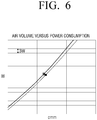
- FIG. 6 is a diagram illustrating a comparison between a value of power consumption to an air volume in a blower fan according to an embodiment of the present invention and a value of power consumption to an air volume in a blower fan (in which an uneven part and a tail wing part are not included) in the related art.
- the blower fan 200 according to an embodiment of the present invention has an effect that the noise of about 1dBA is reduced under the same air volume condition as compared with a blower fan in the related art.
- the blower fan 200 according to an embodiment of the present invention has an effect that the power consumption of about 3W is reduced under the same air volume condition as compared with a blower fan in the related art.
- the mixing action of the flow of a pressure surface and the flow of a negative pressure surface may be increased by forming the uneven part 130 and the tail wing part 140 in the wing 120 and thus the counter current strength of the counter current region and the counter current region in a slipstream may be reduced.
- the power consumption of the blower fan 200 may be reduced and the noise which may be generated in air suction and discharge process may be reduced and thus the satisfaction of the user may be improved.
- the uneven part 130 and the tail wing part 140 may be provided to correspond to each wing 120.
- a shape, a size, the number of uneven parts 130 and the like are not limited thereto and may be changed according to the structure and shape of the applied blower fan 200.
- the shapes of the plurality of protruding portions 131 and recessed portions 132 constituting the uneven part 130 may be differently formed from each other.
- the height of the protruding portion 131 close to the hub 110 may be formed larger than the protruding portion 131 close to the tail wing part 140.
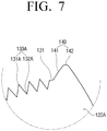
- FIG. 7 is a diagram illustrating a modified example of the wing illustrated in FIG. 4
- FIG. 8 is a diagram illustrating another modified example of the wing illustrated in FIG. 4 .
- uneven parts 130A and 130B may have a polygonal shape.
- a protruding portion 131A may have a triangular shape.
- the protruding portion 131A may have an equilateral triangular shape or an isosceles triangular shape of which a cross-sectional area is constantly reduced upward.
- the protruding portions 131A may be continuously arranged at intervals and the recessed portions 132A may be formed between the protrusion portions 131A.
- the protruding portions 131A and the recessed portions 132A may have a symmetrical shape with each other with respect to the surface of the trailing edge 121.
- the protruding portion 131A may be provided to protrude from the trailing edge 121 and the recessed portion 132A may be provided to be recessed from the trailing edge 121.
- the protruding portion 131B may have a trapezoidal shape of which a cross-sectional area is constantly reduced upward.
- the protruding portions 131B may be continuously arranged at intervals and the recessed portions 132B may be formed between the protrusion portions 131B.
- the protruding portions 131B and the recessed portions 132B may have a symmetrical shape with each other with respect to the surface of the trailing edge 121.
- the protruding portion 131B may be provided to protrude from the trailing edge 121 and the recessed portion 132B may be provided to be recessed from the trailing edge 121.
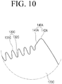
- FIG. 9 is a front view illustrating a blower fan according to another embodiment of the present invention and FIG. 10 is an enlarged diagram illustrating a B portion of the blower fan illustrated in FIG. 9 .
- a protruding portion 131C protrudes the surface of the trailing edge 121 and a recessed portion 132C is recessed from the surface of the trailing edge 121.
- a position P2' of an uneven part 130C may be located in a section 0.5*D ⁇ P2' ⁇ 0.9*D on the basis of the maximum straight distance D.
- a tail wing part 140A may have an inclined portion 141A and a convex portion 142A.
- the convex portion 142A is formed in the outer side of the uneven part 130C.
- the convex portion 142A is arranged on the outer side of the uneven part 130C and has a protruding shape from the trailing edge 121.
- the convex portion 142A may have a preset curvature to protrude toward a rear side with respect to the rotational direction of the blower fan 200 and a front end of the convex portion 142A may be formed higher than a front end of the protruding portion 131C.
- the inclined portion 141A is coupled to an inner side of the convex portion 142A and is arranged to be inclined upward toward the convex portion 142A.
- a position P1' of the of the tail wing part 140A may be located in a section 0.85*D ⁇ P1' ⁇ D on the basis of the maximum straight distance D.
- the uneven part 130C may be formed on the tail wing part 140A.
- the position P1' of the tail wing part 140A means that the tail wing part 140A may be located in the section 0.85*D ⁇ P1' ⁇ D in the distance D from the center C of the hub 110 to an end portion of a wing 120C.
- the outer end of the tail wing part 140A may be the end portion of the wing 120C.
- the width of the tail wing part 140A may have the largest width in response to the inner end of the tail wing part 140A being arranged in 0.85*D. In response to an inner portion of the tail wing part 140A being located in a section between 0.85*D and D, the width of the tail wing part 140A may be flexibly changed.
- the position P2' of the uneven part 130C means that the uneven part 130C may be located in the section 0.5*D ⁇ P2' ⁇ 0.9*D in the distance D from the center C of the hub 110 to the edge portion of the wing 120C.
- the width of the uneven part 130C may be flexibly changed in the section 0.5*D ⁇ P2' ⁇ 0.9*D.
- the position P2' of the uneven part 130C may be formed in 0.5*D ⁇ P2' ⁇ 0.89*D.
- the position P2' of the uneven part 130C may be formed to partially overlap the position P1' of the tail wing part 140A (0.86*D ⁇ P1' ⁇ P2' ⁇ 0.89*D).
- the uneven part 130C may be formed on the inclined portion 141A.
- the blower fan 200 can mix the flow of the pressure surface and the flow of the negative pressure surface near the uneven part 130, the blower fan 200 may effectively reduce the strength and region of the counter current which may be generated in the discharged air.
- the blower fan can simultaneously reduce the noise and power consumption through control of the generation of the counter current.
Landscapes
- Engineering & Computer Science (AREA)
- Mechanical Engineering (AREA)
- General Engineering & Computer Science (AREA)
- Chemical & Material Sciences (AREA)
- Combustion & Propulsion (AREA)
- Structures Of Non-Positive Displacement Pumps (AREA)
Abstract
Description
- The present disclosure relates to a blower fan and an air conditioner having the same, and more particularly, to a blower fan capable of reducing blowing noise and power consumption due to an operation of a propeller fan and an air conditioner having the same.
- Air conditioner is an apparatus which keeps indoor air fresh to be suitable for human activity using a refrigeration cycle. The air conditioner cools the room through a repetitive operation which sucks hot air in a room, heat-exchanges the hot air into a low-temperature refrigerant, and discharges the refrigerant to the room. The air conditioners may heat the room through the reverse operation to the repetitive operation.
- The air conditioner may cool or heat the room through a cooling cycle in which the air circulates in a compressor, a condenser, an expansion valve, and an evaporator in the forward or reverse direction. The compressor provides the high-temperature and high-pressure gaseous refrigerant and the condenser provides the room-temperature and high-pressure liquid refrigerant. The expansion value reduces the pressure of the room-temperature and high-pressure liquid refrigerant and the evaporator evaporates the pressure- reduced refrigerant to a low-temperature gas state.
- The air conditioners may be divided into a separate type air conditioner in which an outdoor unit and an indoor unit are separated from each other and an integrated type air conditioner in which the indoor unit and the outdoor unit are integrally installed. Typically, in the separated type air conditioner, the compressor and the condenser (outdoor heat exchanger) are provided in the outdoor unit and the evaporator (indoor heat exchanger) is provided in the indoor unit. The refrigerant circulates and flows in the outdoor unit and the indoor unit via a pipe which couples the indoor unit and the outdoor unit.
- The outdoor unit in the separate type air conditioner includes the compressor, the condenser, a blower fan, a driving motor which rotates the blower fan, and the like. The driving motor rotates the blower fan, condenses the refrigerant to a liquid state through heat exchange with the gaseous refrigerant flowing inside the condenser of the outdoor unit, and discharges the condensed refrigerant to the outside.
- The object of the present disclosure is to provide a blower fan capable of reducing blowing noise and power consumption and an air conditioner having the same.
- According to an embodiment of the present invention, a blower fan may include a hub coupled to a driving member and configured to receive rotation force; and a plurality of wings radially arranged along a circumference of the hub. Each of the plurality of wings may include an uneven part formed at a trailing edge which is a rear edge portion of the wing with respect to a rotational direction thereof; and a tail wing part having a convex portion which is formed on an outer side of the uneven part and protrudes rather than the uneven part.
- A position P1 of the tail wing part may be located in a section 0.85*D≤P1≤D on the basis of a maximum straight distance D of the wing from a center C of the hub.
- A position P2 of the uneven part may be located in the section 0.5*D≤P2≤0.9*D.
- The uneven part may be located from an inner end of the tail wing part toward the center C of the hub by an interval of 0.01*D or less..
- The tail wing part may have an inclined portion which is coupled to an inner side of the convex portion and is arranged to be inclined upward toward the convex portion.
- A protruding portion of the uneven part which protrudes from a surface of the trailing edge and a recessed portion of the uneven part which is recessed from the surface of the trailing edge may be alternately arranged and the recessed portion may be located closest to the convex portion.
- The protruding portion may have a convex shape to have a preset curvature.
- The protruding portion may have a polygonal shape.
- The convex portion may have a convex shape to have a preset curvature and protrude backward rather than the uneven part with respect to the rotational direction.
- An outer end of the tail wing part may be located in an end portion of the wing.
- According to an embodiment of the present invention, an air conditioner may include a blower fan configured to cool a refrigerant. The blower fan may have a plurality of wings. Each of the plurality of wings may include an uneven part formed at a trailing edge which is a rear edge portion of the wing with respect to a rotational direction thereof; and a convex portion formed on an outer side of the uneven part and having a preset curvature to protrude backward rather than the uneven part with respect to the rotational direction.
- The wing may further include a tail wing part formed in an end portion of a trailing edge of the wing and the convex portion may be provided in the tail wing part.
- The blower fan may further include a hub coupled to a driving shaft and configured to receive rotation force.
- The plurality of wings may be arranged along a circumference of the hub. A position P1 of the tail wing part may be located in a section 0.85*D≤P1≤D on the basis of a maximum straight distance D of the wing from a center C of the hub.
- A position P2 of the uneven part may be located in a section 0.5*D≤P2≤0.9*D.
- The uneven part may be located from an inner end of the tail wing part toward the center C of the hub by an interval of 0.01*D or less.
- The tail wing part may have an inclined portion which is coupled to an inner side of the convex portion and is arranged to be inclined upward toward the convex portion.
- A protruding portion of the uneven part which protrudes from a surface of the trailing edge and a recessed portion of the uneven part which is recessed from the surface of the trailing edge may be alternately arranged and the recessed portion may be located closest to the convex portion.
- The protruding portion may have a convex shape to have a preset curvature.
- The protruding portion may have a polygonal shape.
- An outer end of the tail wing part may be located in an end portion of the wing. To obtain the above-described object, according to an embodiment of the present invention, an air conditioner may include a blower fan configured to cool a refrigerant. The blower fan may have a plurality of wings.
- Each of the plurality of wings may include an uneven part formed at a trailing edge which is a rear edge portion of the wing with respect to a rotational direction thereof; and a convex portion formed on an outer side of the uneven part and having a preset curvature to protrude from the uneven part.
-
-
FIG. 1 is a schematic diagram illustrating an air conditioner according to an embodiment of the present invention. -
FIG. 2 is a perspective view illustrating a figure of a blower fan according to an embodiment of the present invention. -
FIG. 3 is a front view illustrating a figure of a blower fan according to an embodiment of the present invention. -
FIG. 4 is an enlarged view illustrating an A portion of the blower fan illustrated inFIG. 3 . -
FIG. 5 is a diagram illustrating a comparison between a magnitude of noise to an air volume in a blower fan according to an embodiment of the present invention and a magnitude of noise to an air volume in a blower fan in the related art. -
FIG. 6 is a diagram illustrating a comparison between a value of power consumption to an air volume in a blower fan according to an embodiment of the present invention and a value of power consumption to an air volume in a blower fan in the related art. -
FIG. 7 is a diagram illustrating a modified example of a wing illustrated inFIG. 4 . -
FIG. 8 is a diagram illustrating another modified example of a wing illustrated inFIG. 4 . -
FIG. 9 is a front view illustrating a blower fan according to another embodiment of the present invention. -
FIG. 10 is an enlarged view illustrating a B portion of the blower fan illustrated inFIG. 9 . - Hereinafter, embodiments of the present invention will be described in detail with reference to the accompanying
FIGS. 1 to 10 . The embodiments described herein will be exemplarily described based on embodiments most suitable to understand technical features of the present invention. It is understood that the technical features of the present invention are not limited by the embodiments described herein but are illustrated to implement the present invention like the embodiments described herein. - Various modifications, equivalents, and/or alternatives of the embodiments may be included therein without departing from the principles and spirit of the present disclosure. In the following description, unless otherwise described, the same reference numerals are used for the same elements when they are depicted in different drawings.
-
FIG. 1 is a schematic diagram illustrating an air conditioner according to an embodiment of the present invention. Referring toFIG. 1 , anair conditioner 100 includes anindoor unit 10 and anoutdoor unit 20. Theindoor unit 10 and theoutdoor unit 20 may be coupled to acoupling pipe 30. Thecoupling pipe 30 may include arefrigerant supply pipe 40 and arefrigerant discharge pipe 50. The refrigerant may circulate in a refrigerant tube (not shown) provided in theindoor unit 10 and a refrigerant tube (not shown) provided in theoutdoor unit 20 through thecoupling pipe 30. - The
indoor unit 10 may maintain the indoor temperature to an appropriate temperature by discharging the air heat-exchanged with the refrigerant compressed and condensed in theoutdoor unit 20 to the room. Theindoor unit 10 may include an expansion value and an evaporator. The indoor air may be cooled through the refrigerant evaporated in the evaporator. - The
outdoor unit 20 may include a compressor, a condenser, and ablower fan 200. An air inlet through which external air flows in or flows out may be formed in one side of theoutdoor unit 20. The compressor compresses the refrigerant and the compressed refrigerant flows and is condensed in the condenser. At this time, theblower fan 200 may be driven and the heat generated in the condenser may be cooled through the external air flowing through the air inlet and then discharged to the outside of theoutdoor unit 20 again through theblower fan 200. - A propeller fan may be used as the
blower fan 200 of theoutdoor unit 20. Theblower fan 200 may be used in theoutdoor unit 20 of theair conditioner 100 and the like and may allow the air to forcibly flow by a difference between pressures in the front and rear of the blower fan. - Hereinafter, a structure of a blower fan will be described in detail with reference to the accompanying drawings.
-
FIG. 2 is a perspective view illustrating a figure of a blower fan according to an embodiment of the present invention andFIG. 3 is a front view illustrating a figure of a blower fan according to an embodiment of the present invention. Further,FIG. 4 is an enlarged view illustrating an A portion of the blower fan illustrated inFIG. 3 . Referring toFIGS. 2 to 4 , theblower fan 200 according to an embodiment of the present invention includes ahub 110 and a plurality ofwings 120. - A shaft (not shown) of a driving member (not shown) may be coupled to the
hub 110. Thehub 110 is firmly coupled to the shaft of the driving member through a screw fastening structure and the like and receives rotational force from the shaft. Accordingly, theblower fan 200 may be rotated through the driving force of the driving member. For example, the driving member may be a driving motor. - The
wings 120 may be radically arranged in a circumference of thehub 110 at intervals. The plurality ofwings 120 may be provided in the same shape. Each of thewings 120 may be provided to have a gentle slope so as to blow the air in the rear of theblower fan 200 to a forward direction along an axis direction. - The
wing 120 may include a trailingedge 121 and aleading edge 122. Theleading edge 122 refers to a front edge portion with respect to a rotational direction (a clockwise direction on the basis ofFIG. 3 ) of thewing 120 and the trailingedge 121 refers to a rear edge portion with respect to the rotational direction of thewing 120. The leadingedges 122 and the trailingedges 121 of the wings may be arranged close to each other to face each other. - The air flowing into a
wing 120 side through theleading edge 122 according to the rotation of theblower fan 200 flows along the front surface of thewing 120 and is discharged from the trailingedge 121. Thewing 120 may be provided to have a gentle slope toward the front of theblower fan 200 from theleading edge 122 toward the trailingedge 121. Accordingly, in response to the rotation of theblower fan 200, the air flowing into theleading edge 122 may flow along the front surface of thewing 120 inclined toward the front of theblower fan 200 and thus the air may be blown along the axis direction of theblower fan 200 from the rear of theblower fan 200 to the front thereof. - The trailing
edge 121 may have anuneven part 130 and atail wing part 140. Theuneven part 130 may have a protrudingportion 131 and a recessedportion 132 so that the trailingedge 121 is curved. The protrudingportion 131 and the recessedportion 132 are alternately arranged so that theuneven part 130 may have a curved shape. - For example, the protruding
portion 131 may have a crest shape of a wave and the recessedportion 132 may have a trough shape of the wave. Accordingly, theuneven part 130 may have a wave shape having the crest and trough periodically. The protrudingportion 131 and the recessedportion 132 may have a preset curvature. - The protruding
portion 131 protrudes from a surface of the trailingedge 121 and the recessedportion 132 may be recessed from the surface of the trailingedge 121. A position P2 of theuneven part 130 may be located in a section 0.5*D≤P2≤0.9*D on the basis of a distance (hereinafter, referred to as maximum straight distance D) from the center C of thehub 110 to an end portion of thewing 120. - Here, the position P2 of the
uneven part 130 means that theuneven part 130 may be located in the section 0.5*D≤P2≤0.9*D in the distance D from the center C of thehub 110 to the end portion of thewing 120 and the position P2 of theuneven part 130 may correspond to a length of theuneven part 130. A width of theuneven part 130 in the position P2 may be flexibly changed within the section 0.5*D≤P2≤0.9*D. - The
tail wing part 140 may be located in the outer side of theuneven part 130 and have aninclined portion 141 and aconvex portion 142. Theconvex portion 142 is formed in the outer side of theuneven part 130. Theconvex portion 142 is arranged in the outer side of theuneven part 130 and has a protruding shape from the trailingedge 121. Theconvex portion 142 may have a preset curvature to protrude toward a rear side with respect to the rotational direction of theblower fan 200 and a front end of theconvex portion 142 may be formed higher than a front end of the protrudingportion 131. - The
inclined portion 141 is coupled to an inner side of theconvex portion 142 and is coupled to be inclined upward toward theconvex portion 142. Although theinclined portion 141 is illustrated in a linear shape, theinclined portion 141 may have a curved form to be inclined upward toward theconvex portion 142. A position P1 of thetail wing part 140 may be located in a section 0.85*D≤P1≤D on the basis of the maximum straight distance D. - Here, the position P1 of the
tail wing part 140 means that thetail wing part 140 may be located in the section 0.85*D≤P1≤D in the distance D from the center C of thehub 110 to the end portion of thewing 120. Here, the outer end of thetail wing part 140 may be arranged in the end portion of thewing 120. The width of thetail wing part 140 may have the largest width in response to the inner end of thetail wing part 140 being arranged in 0.85*D. For example, the width of thetail wing part 140 may be 0.15*D. In response to an inner portion of thetail wing part 140 being located in a section between 0.85*D and D, the width of thetail wing part 140 may be flexibly changed. - Referring to
FIG. 4 , theuneven part 130 may be formed from an inner side of the tail wing part 140 (or inclined portion 141) toward the center C of thehub 110 and a pitch of theuneven part 130 may be located to have an interval d of 0.01*D or less on the basis of the maximum straight distance D. The protrudingportion 131 may protrude to a present height h from the surface of the trailingedge 121. -
FIG. 5 is a diagram illustrating a comparison between a magnitude of noise to an air volume in a blower fan according to an embodiment of the present invention and a magnitude of noise to an air volume in a blower fan (in which an uneven part and a tail wing part are not included) in the related art andFIG. 6 is a diagram illustrating a comparison between a value of power consumption to an air volume in a blower fan according to an embodiment of the present invention and a value of power consumption to an air volume in a blower fan (in which an uneven part and a tail wing part are not included) in the related art. - It can be seen from
FIG. 5 that theblower fan 200 according to an embodiment of the present invention has an effect that the noise of about 1dBA is reduced under the same air volume condition as compared with a blower fan in the related art. - It can be seen from
FIG. 6 that theblower fan 200 according to an embodiment of the present invention has an effect that the power consumption of about 3W is reduced under the same air volume condition as compared with a blower fan in the related art. - Accordingly, the mixing action of the flow of a pressure surface and the flow of a negative pressure surface may be increased by forming the
uneven part 130 and thetail wing part 140 in thewing 120 and thus the counter current strength of the counter current region and the counter current region in a slipstream may be reduced. As the counter current is reduced, the power consumption of theblower fan 200 may be reduced and the noise which may be generated in air suction and discharge process may be reduced and thus the satisfaction of the user may be improved. - The
uneven part 130 and thetail wing part 140 may be provided to correspond to eachwing 120. A shape, a size, the number ofuneven parts 130 and the like are not limited thereto and may be changed according to the structure and shape of the appliedblower fan 200. The shapes of the plurality of protrudingportions 131 and recessedportions 132 constituting theuneven part 130 may be differently formed from each other. For example, the height of the protrudingportion 131 close to thehub 110 may be formed larger than the protrudingportion 131 close to thetail wing part 140. - Hereinafter, modification examples of the
wing 120 according to an embodiment described inFIGS. 1 to 4 will be described. The modification examples to be described later will be described on the basis of a difference from the wing described inFIGS. 1 to 4 and omitted description may be replaced with the above-described contents. -
FIG. 7 is a diagram illustrating a modified example of the wing illustrated inFIG. 4 andFIG. 8 is a diagram illustrating another modified example of the wing illustrated inFIG. 4 . As illustrated inFIGS. 7 and8 ,uneven parts - Referring to
FIG. 7 , a protrudingportion 131A may have a triangular shape. The protrudingportion 131A may have an equilateral triangular shape or an isosceles triangular shape of which a cross-sectional area is constantly reduced upward. - The protruding
portions 131A may be continuously arranged at intervals and the recessedportions 132A may be formed between theprotrusion portions 131A. The protrudingportions 131A and the recessedportions 132A may have a symmetrical shape with each other with respect to the surface of the trailingedge 121. The protrudingportion 131A may be provided to protrude from the trailingedge 121 and the recessedportion 132A may be provided to be recessed from the trailingedge 121. - Referring to
FIG. 8 , the protrudingportion 131B may have a trapezoidal shape of which a cross-sectional area is constantly reduced upward. The protrudingportions 131B may be continuously arranged at intervals and the recessedportions 132B may be formed between theprotrusion portions 131B. The protrudingportions 131B and the recessedportions 132B may have a symmetrical shape with each other with respect to the surface of the trailingedge 121. The protrudingportion 131B may be provided to protrude from the trailingedge 121 and the recessedportion 132B may be provided to be recessed from the trailingedge 121. -
FIG. 9 is a front view illustrating a blower fan according to another embodiment of the present invention andFIG. 10 is an enlarged diagram illustrating a B portion of the blower fan illustrated inFIG. 9 . As described inFIGS. 1 to 4 , a protrudingportion 131C protrudes the surface of the trailingedge 121 and a recessedportion 132C is recessed from the surface of the trailingedge 121. - A position P2' of an
uneven part 130C may be located in a section 0.5*D≤P2'≤0.9*D on the basis of the maximum straight distance D. - A
tail wing part 140A may have aninclined portion 141A and aconvex portion 142A. Theconvex portion 142A is formed in the outer side of theuneven part 130C. Theconvex portion 142A is arranged on the outer side of theuneven part 130C and has a protruding shape from the trailingedge 121. Theconvex portion 142A may have a preset curvature to protrude toward a rear side with respect to the rotational direction of theblower fan 200 and a front end of theconvex portion 142A may be formed higher than a front end of the protrudingportion 131C. - The
inclined portion 141A is coupled to an inner side of theconvex portion 142A and is arranged to be inclined upward toward theconvex portion 142A. A position P1' of the of thetail wing part 140A may be located in a section 0.85*D≤P1'≤D on the basis of the maximum straight distance D. - Referring to
FIGS. 9 and10 , theuneven part 130C may be formed on thetail wing part 140A. - Here, the position P1' of the
tail wing part 140A means that thetail wing part 140A may be located in the section 0.85*D≤P1'≤D in the distance D from the center C of thehub 110 to an end portion of awing 120C. Here, the outer end of thetail wing part 140A may be the end portion of thewing 120C. - At this time, the width of the
tail wing part 140A may have the largest width in response to the inner end of thetail wing part 140A being arranged in 0.85*D. In response to an inner portion of thetail wing part 140A being located in a section between 0.85*D and D, the width of thetail wing part 140A may be flexibly changed. - Here, the position P2' of the
uneven part 130C means that theuneven part 130C may be located in the section 0.5*D≤P2'≤0.9*D in the distance D from the center C of thehub 110 to the edge portion of thewing 120C. The width of theuneven part 130C may be flexibly changed in the section 0.5*D≤P2'≤0.9*D. - For example, in response to the position P1' of the
tail wing part 140A being formed in 0.86*D≤P1'≤D, the position P2' of theuneven part 130C may be formed in 0.5*D≤P2'≤0.89*D. In this case, the position P2' of theuneven part 130C may be formed to partially overlap the position P1' of thetail wing part 140A (0.86*D ≤ P1'∩P2' ≤ 0.89*D). In response to a distance ratio of theinclined portion 141A and theconvex portion 142A being 1:1, theuneven part 130C may be formed on theinclined portion 141A. - In the
blower fans 200 described in the embodiments of the present invention, air flows in along theleading edge 122. The flowing-in air flows along thewing 120 and the flow of the air may be changed through theuneven part 130 and thetail wing part 140 provided in the trailingedge 121 in response to the air being discharged to thetraining edge 121. - At this time, since the
blower fan 200 can mix the flow of the pressure surface and the flow of the negative pressure surface near theuneven part 130, theblower fan 200 may effectively reduce the strength and region of the counter current which may be generated in the discharged air. The blower fan can simultaneously reduce the noise and power consumption through control of the generation of the counter current. - The various embodiments of the present invention have been separately described above, but the embodiments may not be inevitably separately implemented and the configuration and operation of each of the embodiments may be implemented through the combination of at least one of other embodiments.
- The foregoing exemplary embodiments and advantages are merely exemplary and are not to be construed as limiting the present inventive concept. The description of the exemplary embodiments is intended to be illustrative, and not to limit the scope of the claims, and many alternatives, modifications, and variations will be apparent to those skilled in the art.
Claims (15)
- A blower fan comprising:a hub coupled to a driving member and configured to receive rotation force; anda plurality of wings radially arranged along a circumference of the hub,wherein each of the plurality of wings includes an uneven part formed at a trailing edge which is a rear edge portion of the wing with respect to a rotational direction thereof; and a tail wing part having a convex portion which is formed on an outer side of the uneven part and protrudes rather than the uneven part.
- The blower fan according to claim 1, wherein a position P1 of the tail wing part is located in a section 0.85*D≤P1≤D on the basis of a maximum straight distance D from a center C of the hub to an end portion of the wing.
- The blower fan according to claim 2, wherein a position P2 of the uneven part is located in the section 0.5*D≤P2≤0.9*D.
- The blower fan according to claim 3, wherein the uneven part is located from an inner end of the trail wing part toward the center C of the hub by an interval of 0.01*D or less.
- The blower fan according to claim 1, wherein the tail wing part has an inclined portion which is coupled to an inner side of the convex portion and is arranged to be inclined upward toward the convex portion.
- The blower fan according to claim 1, wherein a protruding portion of the uneven part which protrudes from a surface of the trailing edge and a recessed portion of the uneven part which is recessed from the surface of the trailing edge are alternately arranged and the recessed portion is located closest to the convex portion.
- The blower fan according to claim 6, wherein the protruding portion has a convex shape to have a preset curvature.
- The blower fan according to claim 6, wherein the protruding portion has a polygonal shape.
- The blower fan according to claim 1, wherein the convex portion has a convex shape to have a preset curvature and protrudes backward rather than the uneven part with respect to the rotational direction.
- The blower fan according to claim 2, wherein an outer end of the tail wing part is located in the end portion of the wing.
- An air conditioner comprising:a blower fan configured to cool a refrigerant,wherein the blower fan has a plurality of wings and each of the plurality of wings includes an uneven part formed at a trailing edge which is a rear edge portion of the wing with respect to a rotational direction thereof; and a convex portion formed on an outer side of the uneven part and having a preset curvature to protrude backward rather than the uneven part with respect to the rotational direction.
- The air conditioner according to claim 11, wherein the wing further includes a tail wing part formed in an end portion of a trailing edge of the wing and the convex portion is provided in the tail wing part.
- The air conditioner according to claim 12, wherein the blower fan further includes a hub coupled to a driving shaft and configured to receive rotation force, the plurality of wings are arranged along a circumference of the hub, and a position P1 of the tail wing part is located in a section 0.85*D≤P1≤D on the basis of a maximum straight distance D of the wing from a center C of the hub.
- The air conditioner according to claim 13, wherein a position P2 of the uneven part is located in a section 0.5*D≤P2≤0.9*D.
- The air conditioner according to claim 14, wherein the uneven part is located from an inner end of the trail wing part toward the center C of the hub by a section of 0.01*D or less.
Applications Claiming Priority (2)
| Application Number | Priority Date | Filing Date | Title |
|---|---|---|---|
| KR1020150168770A KR102479815B1 (en) | 2015-11-30 | 2015-11-30 | Blowing fan and air conditioner having the same |
| PCT/KR2016/012616 WO2017095029A1 (en) | 2015-11-30 | 2016-11-04 | Blower fan and air conditioner having same |
Publications (3)
| Publication Number | Publication Date |
|---|---|
| EP3343045A1 true EP3343045A1 (en) | 2018-07-04 |
| EP3343045A4 EP3343045A4 (en) | 2018-10-03 |
| EP3343045B1 EP3343045B1 (en) | 2021-07-21 |
Family
ID=58797597
Family Applications (1)
| Application Number | Title | Priority Date | Filing Date |
|---|---|---|---|
| EP16870925.1A Active EP3343045B1 (en) | 2015-11-30 | 2016-11-04 | Blower fan and air conditioner having same |
Country Status (5)
| Country | Link |
|---|---|
| US (1) | US11041506B2 (en) |
| EP (1) | EP3343045B1 (en) |
| KR (1) | KR102479815B1 (en) |
| CN (1) | CN108291559B (en) |
| WO (1) | WO2017095029A1 (en) |
Cited By (1)
| Publication number | Priority date | Publication date | Assignee | Title |
|---|---|---|---|---|
| EP3859164A4 (en) * | 2018-09-25 | 2022-06-15 | York Guangzhou Air Conditioning and Refrigeration Co., Ltd. | Blade and axial flow impeller using same |
Families Citing this family (13)
| Publication number | Priority date | Publication date | Assignee | Title |
|---|---|---|---|---|
| USD289525S (en) * | 1984-10-01 | 1987-04-28 | Industrial Tools, Inc. | Slicing machine for magnetic tape or the like |
| USD901669S1 (en) * | 2017-09-29 | 2020-11-10 | Carrier Corporation | Contoured fan blade |
| CN207795681U (en) * | 2018-01-13 | 2018-08-31 | 广东美的环境电器制造有限公司 | Axial flow fan leaf, axial flow fan blade component, axial flow blower ducting assembly |
| KR102174944B1 (en) * | 2018-03-16 | 2020-11-05 | 주식회사 홀로홀릭 | Fan device with fan display |
| WO2019210591A1 (en) * | 2018-05-04 | 2019-11-07 | 广东美的制冷设备有限公司 | Axial flow wind wheel, air conditioner outdoor unit and air conditioner |
| US11680580B2 (en) * | 2018-11-22 | 2023-06-20 | Gd Midea Air-Conditioning Equipment Co., Ltd. | Axial-flow impeller and air-conditioner having the same |
| USD972119S1 (en) * | 2018-11-28 | 2022-12-06 | Ebm-Papst Mulfingen Gmbh & Co. Kg | Fan |
| USD971398S1 (en) * | 2019-03-04 | 2022-11-29 | Ebm-Papst Mulfingen Gmbh & Co. Kg | Fan wheel of an axial fan |
| USD980409S1 (en) * | 2019-03-07 | 2023-03-07 | Ziehl-Abegg Se | Fan wheel |
| USD980965S1 (en) | 2019-05-07 | 2023-03-14 | Carrier Corporation | Leading edge of a fan blade |
| US11187083B2 (en) | 2019-05-07 | 2021-11-30 | Carrier Corporation | HVAC fan |
| WO2020234997A1 (en) * | 2019-05-21 | 2020-11-26 | 三菱電機株式会社 | Axial fan, blower, and refrigeration cycle apparatus |
| TWI801140B (en) * | 2022-02-18 | 2023-05-01 | 宏碁股份有限公司 | Axial fan |
Family Cites Families (27)
| Publication number | Priority date | Publication date | Assignee | Title |
|---|---|---|---|---|
| JPS5115210A (en) * | 1974-07-02 | 1976-02-06 | Rotoron Inc | Zatsuongenshono fuan |
| JP2613272B2 (en) | 1988-08-29 | 1997-05-21 | 株式会社日立製作所 | Axial fan |
| JP3598900B2 (en) | 1999-09-03 | 2004-12-08 | ダイキン工業株式会社 | Impeller for blower |
| JP4158393B2 (en) | 2002-03-26 | 2008-10-01 | 富士電機機器制御株式会社 | Propeller fan |
| KR200314840Y1 (en) | 2003-02-21 | 2003-05-27 | 주식회사 세원기연 | Low noise type fan |
| JP4689262B2 (en) | 2004-12-21 | 2011-05-25 | 東芝キヤリア株式会社 | Axial fan, outdoor unit of air conditioner |
| CN200940604Y (en) | 2006-08-07 | 2007-08-29 | 海信集团有限公司 | Axial flow fan of air conditioner |
| JP4388992B1 (en) | 2008-10-22 | 2009-12-24 | シャープ株式会社 | Propeller fan, fluid feeder and mold |
| KR101659620B1 (en) * | 2009-12-28 | 2016-09-27 | 엘지전자 주식회사 | Axial fan |
| KR20130039481A (en) * | 2011-10-12 | 2013-04-22 | 엘지전자 주식회사 | Axial flow fan and air conditioner |
| JP2013130125A (en) | 2011-12-21 | 2013-07-04 | Toshiba Carrier Corp | Propeller fan and heat source unit using the same |
| WO2013154100A1 (en) | 2012-04-10 | 2013-10-17 | シャープ株式会社 | Propeller fan, fluid sending device, electric fan, and mold for molding |
| JP6154990B2 (en) | 2012-04-10 | 2017-06-28 | シャープ株式会社 | Propeller fan for electric fan, electric fan equipped with the same, and mold for molding propeller fan for electric fan |
| CN202833299U (en) | 2012-06-11 | 2013-03-27 | 广东美的制冷设备有限公司 | Axial wind wheel |
| JP6170783B2 (en) | 2012-09-19 | 2017-07-26 | 東芝キヤリア株式会社 | Outdoor unit of propeller fan and air conditioner |
| WO2014050146A1 (en) | 2012-09-28 | 2014-04-03 | ダイキン工業株式会社 | Propeller fan and air conditioner equipped with same |
| CN202914390U (en) | 2012-11-23 | 2013-05-01 | 青岛海尔空调电子有限公司 | Axial fan and air conditioner outdoor machine |
| KR20140125522A (en) * | 2013-04-19 | 2014-10-29 | 엘지전자 주식회사 | turbo fan |
| KR20140136180A (en) * | 2013-05-20 | 2014-11-28 | 삼성전자주식회사 | Propeller fan and air conditioner having the same |
| KR101494835B1 (en) | 2013-06-11 | 2015-02-23 | 시스템벤트 주식회사 | A diffusing apparatus of indoor air |
| JP5980180B2 (en) * | 2013-08-08 | 2016-08-31 | 三菱電機株式会社 | Axial flow fan and air conditioner having the axial flow fan |
| KR20150133077A (en) * | 2014-05-19 | 2015-11-27 | 엘지전자 주식회사 | Brower apparatus and air conditioner having the same |
| CN204126956U (en) | 2014-06-06 | 2015-01-28 | 杭州微光电子股份有限公司 | A kind of axial flow fan vane wheel for high efficiency motor |
| CN204572556U (en) * | 2015-02-12 | 2015-08-19 | 美的集团武汉制冷设备有限公司 | Air conditioner outdoor machine and air conditioner |
| CN204553335U (en) | 2015-03-13 | 2015-08-12 | 广东顺威精密塑料股份有限公司 | A kind of novel axial-flow leaf |
| CN204716616U (en) | 2015-06-15 | 2015-10-21 | 广东顺威精密塑料股份有限公司 | A kind of highly effective low noise axial-flow windwheel of air conditioner outdoor machine |
| JP6926428B2 (en) * | 2016-09-27 | 2021-08-25 | 株式会社富士通ゼネラル | Axial fan and outdoor unit using it |
-
2015
- 2015-11-30 KR KR1020150168770A patent/KR102479815B1/en active IP Right Grant
-
2016
- 2016-11-04 WO PCT/KR2016/012616 patent/WO2017095029A1/en active Application Filing
- 2016-11-04 EP EP16870925.1A patent/EP3343045B1/en active Active
- 2016-11-04 CN CN201680067536.2A patent/CN108291559B/en active Active
- 2016-11-04 US US15/780,221 patent/US11041506B2/en active Active
Cited By (2)
| Publication number | Priority date | Publication date | Assignee | Title |
|---|---|---|---|---|
| EP3859164A4 (en) * | 2018-09-25 | 2022-06-15 | York Guangzhou Air Conditioning and Refrigeration Co., Ltd. | Blade and axial flow impeller using same |
| US11572890B2 (en) | 2018-09-25 | 2023-02-07 | Johnson Controls Tyco IP Holdings LLP | Blade and axial flow impeller using same |
Also Published As
| Publication number | Publication date |
|---|---|
| CN108291559B (en) | 2021-07-13 |
| KR20170062947A (en) | 2017-06-08 |
| US20180355885A1 (en) | 2018-12-13 |
| CN108291559A (en) | 2018-07-17 |
| EP3343045B1 (en) | 2021-07-21 |
| US11041506B2 (en) | 2021-06-22 |
| EP3343045A4 (en) | 2018-10-03 |
| KR102479815B1 (en) | 2022-12-23 |
| WO2017095029A1 (en) | 2017-06-08 |
Similar Documents
| Publication | Publication Date | Title |
|---|---|---|
| EP3343045A1 (en) | Blower fan and air conditioner having same | |
| EP2806221A2 (en) | Propeller fan and air conditioner having the same | |
| US9995303B2 (en) | Air conditioner | |
| CN108350898B (en) | Blower, outdoor unit, and refrigeration cycle device | |
| EP3833908B1 (en) | Outdoor unit of air conditioner | |
| KR20130039481A (en) | Axial flow fan and air conditioner | |
| US6863500B2 (en) | Blast fan | |
| US9303646B2 (en) | Cross flow fan and air conditioner | |
| US7398654B2 (en) | Air conditioner | |
| JP2013011235A (en) | Fan, outdoor unit and refrigerating cycle device | |
| US20220221214A1 (en) | Axial flow fan, air-sending device, and refrigeration cycle apparatus | |
| EP2597315B1 (en) | Cross flow fan and air conditioner | |
| US12085303B2 (en) | Outdoor unit of air conditioner | |
| CN210861436U (en) | Air supply fan, air conditioner outdoor unit and air conditioner | |
| CN109891101B (en) | Propeller fan, outdoor unit, and refrigeration cycle device | |
| CN213089943U (en) | Indoor unit of air conditioner | |
| CN214998436U (en) | Air conditioner | |
| CN217004681U (en) | Centrifugal fan and air conditioner with same | |
| US20240318838A1 (en) | Air sending device and air-conditioning apparatus | |
| WO2021152775A1 (en) | Centrifugal blower and air conditioner provided with same | |
| KR20170074378A (en) | Outdoor unit of an air conditioner | |
| CN110762645A (en) | Air supply fan, air conditioner outdoor unit and air conditioner | |
| KR200142509Y1 (en) | Outdoor machine of airconditioner | |
| KR19990011844A (en) | Blower of outdoor unit for air conditioner | |
| KR19990011845A (en) | Blower of outdoor unit for air conditioner |
Legal Events
| Date | Code | Title | Description |
|---|---|---|---|
| STAA | Information on the status of an ep patent application or granted ep patent |
Free format text: STATUS: THE INTERNATIONAL PUBLICATION HAS BEEN MADE |
|
| PUAI | Public reference made under article 153(3) epc to a published international application that has entered the european phase |
Free format text: ORIGINAL CODE: 0009012 |
|
| STAA | Information on the status of an ep patent application or granted ep patent |
Free format text: STATUS: REQUEST FOR EXAMINATION WAS MADE |
|
| 17P | Request for examination filed |
Effective date: 20180328 |
|
| AK | Designated contracting states |
Kind code of ref document: A1 Designated state(s): AL AT BE BG CH CY CZ DE DK EE ES FI FR GB GR HR HU IE IS IT LI LT LU LV MC MK MT NL NO PL PT RO RS SE SI SK SM TR |
|
| AX | Request for extension of the european patent |
Extension state: BA ME |
|
| A4 | Supplementary search report drawn up and despatched |
Effective date: 20180905 |
|
| RIC1 | Information provided on ipc code assigned before grant |
Ipc: F24F 13/20 20060101ALI20180830BHEP Ipc: F04D 25/08 20060101ALI20180830BHEP Ipc: F04D 29/32 20060101AFI20180830BHEP Ipc: F24F 1/56 20110101ALI20180830BHEP Ipc: F04D 29/66 20060101ALI20180830BHEP Ipc: F24F 1/38 20110101ALI20180830BHEP Ipc: F04D 29/38 20060101ALI20180830BHEP |
|
| DAV | Request for validation of the european patent (deleted) | ||
| DAX | Request for extension of the european patent (deleted) | ||
| STAA | Information on the status of an ep patent application or granted ep patent |
Free format text: STATUS: EXAMINATION IS IN PROGRESS |
|
| 17Q | First examination report despatched |
Effective date: 20200506 |
|
| STAA | Information on the status of an ep patent application or granted ep patent |
Free format text: STATUS: EXAMINATION IS IN PROGRESS |
|
| GRAP | Despatch of communication of intention to grant a patent |
Free format text: ORIGINAL CODE: EPIDOSNIGR1 |
|
| STAA | Information on the status of an ep patent application or granted ep patent |
Free format text: STATUS: GRANT OF PATENT IS INTENDED |
|
| INTG | Intention to grant announced |
Effective date: 20210305 |
|
| GRAS | Grant fee paid |
Free format text: ORIGINAL CODE: EPIDOSNIGR3 |
|
| GRAA | (expected) grant |
Free format text: ORIGINAL CODE: 0009210 |
|
| STAA | Information on the status of an ep patent application or granted ep patent |
Free format text: STATUS: THE PATENT HAS BEEN GRANTED |
|
| AK | Designated contracting states |
Kind code of ref document: B1 Designated state(s): AL AT BE BG CH CY CZ DE DK EE ES FI FR GB GR HR HU IE IS IT LI LT LU LV MC MK MT NL NO PL PT RO RS SE SI SK SM TR |
|
| REG | Reference to a national code |
Ref country code: GB Ref legal event code: FG4D |
|
| REG | Reference to a national code |
Ref country code: CH Ref legal event code: EP |
|
| REG | Reference to a national code |
Ref country code: DE Ref legal event code: R096 Ref document number: 602016061094 Country of ref document: DE |
|
| REG | Reference to a national code |
Ref country code: AT Ref legal event code: REF Ref document number: 1412839 Country of ref document: AT Kind code of ref document: T Effective date: 20210815 |
|
| REG | Reference to a national code |
Ref country code: IE Ref legal event code: FG4D |
|
| REG | Reference to a national code |
Ref country code: LT Ref legal event code: MG9D |
|
| REG | Reference to a national code |
Ref country code: NL Ref legal event code: MP Effective date: 20210721 |
|
| REG | Reference to a national code |
Ref country code: AT Ref legal event code: MK05 Ref document number: 1412839 Country of ref document: AT Kind code of ref document: T Effective date: 20210721 |
|
| PG25 | Lapsed in a contracting state [announced via postgrant information from national office to epo] |
Ref country code: LT Free format text: LAPSE BECAUSE OF FAILURE TO SUBMIT A TRANSLATION OF THE DESCRIPTION OR TO PAY THE FEE WITHIN THE PRESCRIBED TIME-LIMIT Effective date: 20210721 Ref country code: BG Free format text: LAPSE BECAUSE OF FAILURE TO SUBMIT A TRANSLATION OF THE DESCRIPTION OR TO PAY THE FEE WITHIN THE PRESCRIBED TIME-LIMIT Effective date: 20211021 Ref country code: AT Free format text: LAPSE BECAUSE OF FAILURE TO SUBMIT A TRANSLATION OF THE DESCRIPTION OR TO PAY THE FEE WITHIN THE PRESCRIBED TIME-LIMIT Effective date: 20210721 Ref country code: NO Free format text: LAPSE BECAUSE OF FAILURE TO SUBMIT A TRANSLATION OF THE DESCRIPTION OR TO PAY THE FEE WITHIN THE PRESCRIBED TIME-LIMIT Effective date: 20211021 Ref country code: NL Free format text: LAPSE BECAUSE OF FAILURE TO SUBMIT A TRANSLATION OF THE DESCRIPTION OR TO PAY THE FEE WITHIN THE PRESCRIBED TIME-LIMIT Effective date: 20210721 Ref country code: PT Free format text: LAPSE BECAUSE OF FAILURE TO SUBMIT A TRANSLATION OF THE DESCRIPTION OR TO PAY THE FEE WITHIN THE PRESCRIBED TIME-LIMIT Effective date: 20211122 Ref country code: HR Free format text: LAPSE BECAUSE OF FAILURE TO SUBMIT A TRANSLATION OF THE DESCRIPTION OR TO PAY THE FEE WITHIN THE PRESCRIBED TIME-LIMIT Effective date: 20210721 Ref country code: ES Free format text: LAPSE BECAUSE OF FAILURE TO SUBMIT A TRANSLATION OF THE DESCRIPTION OR TO PAY THE FEE WITHIN THE PRESCRIBED TIME-LIMIT Effective date: 20210721 Ref country code: FI Free format text: LAPSE BECAUSE OF FAILURE TO SUBMIT A TRANSLATION OF THE DESCRIPTION OR TO PAY THE FEE WITHIN THE PRESCRIBED TIME-LIMIT Effective date: 20210721 Ref country code: RS Free format text: LAPSE BECAUSE OF FAILURE TO SUBMIT A TRANSLATION OF THE DESCRIPTION OR TO PAY THE FEE WITHIN THE PRESCRIBED TIME-LIMIT Effective date: 20210721 Ref country code: SE Free format text: LAPSE BECAUSE OF FAILURE TO SUBMIT A TRANSLATION OF THE DESCRIPTION OR TO PAY THE FEE WITHIN THE PRESCRIBED TIME-LIMIT Effective date: 20210721 |
|
| PG25 | Lapsed in a contracting state [announced via postgrant information from national office to epo] |
Ref country code: PL Free format text: LAPSE BECAUSE OF FAILURE TO SUBMIT A TRANSLATION OF THE DESCRIPTION OR TO PAY THE FEE WITHIN THE PRESCRIBED TIME-LIMIT Effective date: 20210721 Ref country code: LV Free format text: LAPSE BECAUSE OF FAILURE TO SUBMIT A TRANSLATION OF THE DESCRIPTION OR TO PAY THE FEE WITHIN THE PRESCRIBED TIME-LIMIT Effective date: 20210721 Ref country code: GR Free format text: LAPSE BECAUSE OF FAILURE TO SUBMIT A TRANSLATION OF THE DESCRIPTION OR TO PAY THE FEE WITHIN THE PRESCRIBED TIME-LIMIT Effective date: 20211022 |
|
| REG | Reference to a national code |
Ref country code: DE Ref legal event code: R097 Ref document number: 602016061094 Country of ref document: DE |
|
| PG25 | Lapsed in a contracting state [announced via postgrant information from national office to epo] |
Ref country code: DK Free format text: LAPSE BECAUSE OF FAILURE TO SUBMIT A TRANSLATION OF THE DESCRIPTION OR TO PAY THE FEE WITHIN THE PRESCRIBED TIME-LIMIT Effective date: 20210721 |
|
| PLBE | No opposition filed within time limit |
Free format text: ORIGINAL CODE: 0009261 |
|
| STAA | Information on the status of an ep patent application or granted ep patent |
Free format text: STATUS: NO OPPOSITION FILED WITHIN TIME LIMIT |
|
| PG25 | Lapsed in a contracting state [announced via postgrant information from national office to epo] |
Ref country code: SM Free format text: LAPSE BECAUSE OF FAILURE TO SUBMIT A TRANSLATION OF THE DESCRIPTION OR TO PAY THE FEE WITHIN THE PRESCRIBED TIME-LIMIT Effective date: 20210721 Ref country code: SK Free format text: LAPSE BECAUSE OF FAILURE TO SUBMIT A TRANSLATION OF THE DESCRIPTION OR TO PAY THE FEE WITHIN THE PRESCRIBED TIME-LIMIT Effective date: 20210721 Ref country code: RO Free format text: LAPSE BECAUSE OF FAILURE TO SUBMIT A TRANSLATION OF THE DESCRIPTION OR TO PAY THE FEE WITHIN THE PRESCRIBED TIME-LIMIT Effective date: 20210721 Ref country code: EE Free format text: LAPSE BECAUSE OF FAILURE TO SUBMIT A TRANSLATION OF THE DESCRIPTION OR TO PAY THE FEE WITHIN THE PRESCRIBED TIME-LIMIT Effective date: 20210721 Ref country code: CZ Free format text: LAPSE BECAUSE OF FAILURE TO SUBMIT A TRANSLATION OF THE DESCRIPTION OR TO PAY THE FEE WITHIN THE PRESCRIBED TIME-LIMIT Effective date: 20210721 Ref country code: AL Free format text: LAPSE BECAUSE OF FAILURE TO SUBMIT A TRANSLATION OF THE DESCRIPTION OR TO PAY THE FEE WITHIN THE PRESCRIBED TIME-LIMIT Effective date: 20210721 |
|
| 26N | No opposition filed |
Effective date: 20220422 |
|
| PG25 | Lapsed in a contracting state [announced via postgrant information from national office to epo] |
Ref country code: MC Free format text: LAPSE BECAUSE OF FAILURE TO SUBMIT A TRANSLATION OF THE DESCRIPTION OR TO PAY THE FEE WITHIN THE PRESCRIBED TIME-LIMIT Effective date: 20210721 |
|
| REG | Reference to a national code |
Ref country code: CH Ref legal event code: PL |
|
| PG25 | Lapsed in a contracting state [announced via postgrant information from national office to epo] |
Ref country code: LU Free format text: LAPSE BECAUSE OF NON-PAYMENT OF DUE FEES Effective date: 20211104 Ref country code: IT Free format text: LAPSE BECAUSE OF FAILURE TO SUBMIT A TRANSLATION OF THE DESCRIPTION OR TO PAY THE FEE WITHIN THE PRESCRIBED TIME-LIMIT Effective date: 20210721 Ref country code: BE Free format text: LAPSE BECAUSE OF NON-PAYMENT OF DUE FEES Effective date: 20211130 |
|
| REG | Reference to a national code |
Ref country code: BE Ref legal event code: MM Effective date: 20211130 |
|
| PG25 | Lapsed in a contracting state [announced via postgrant information from national office to epo] |
Ref country code: LI Free format text: LAPSE BECAUSE OF NON-PAYMENT OF DUE FEES Effective date: 20211130 Ref country code: CH Free format text: LAPSE BECAUSE OF NON-PAYMENT OF DUE FEES Effective date: 20211130 |
|
| PG25 | Lapsed in a contracting state [announced via postgrant information from national office to epo] |
Ref country code: IE Free format text: LAPSE BECAUSE OF NON-PAYMENT OF DUE FEES Effective date: 20211104 |
|
| PG25 | Lapsed in a contracting state [announced via postgrant information from national office to epo] |
Ref country code: FR Free format text: LAPSE BECAUSE OF NON-PAYMENT OF DUE FEES Effective date: 20211130 |
|
| PG25 | Lapsed in a contracting state [announced via postgrant information from national office to epo] |
Ref country code: HU Free format text: LAPSE BECAUSE OF FAILURE TO SUBMIT A TRANSLATION OF THE DESCRIPTION OR TO PAY THE FEE WITHIN THE PRESCRIBED TIME-LIMIT; INVALID AB INITIO Effective date: 20161104 |
|
| PG25 | Lapsed in a contracting state [announced via postgrant information from national office to epo] |
Ref country code: CY Free format text: LAPSE BECAUSE OF FAILURE TO SUBMIT A TRANSLATION OF THE DESCRIPTION OR TO PAY THE FEE WITHIN THE PRESCRIBED TIME-LIMIT Effective date: 20210721 |
|
| PGFP | Annual fee paid to national office [announced via postgrant information from national office to epo] |
Ref country code: GB Payment date: 20231023 Year of fee payment: 8 |
|
| PGFP | Annual fee paid to national office [announced via postgrant information from national office to epo] |
Ref country code: DE Payment date: 20231023 Year of fee payment: 8 |
|
| PG25 | Lapsed in a contracting state [announced via postgrant information from national office to epo] |
Ref country code: MK Free format text: LAPSE BECAUSE OF FAILURE TO SUBMIT A TRANSLATION OF THE DESCRIPTION OR TO PAY THE FEE WITHIN THE PRESCRIBED TIME-LIMIT Effective date: 20210721 |
|
| PG25 | Lapsed in a contracting state [announced via postgrant information from national office to epo] |
Ref country code: TR Free format text: LAPSE BECAUSE OF FAILURE TO SUBMIT A TRANSLATION OF THE DESCRIPTION OR TO PAY THE FEE WITHIN THE PRESCRIBED TIME-LIMIT Effective date: 20210721 |
|
| PG25 | Lapsed in a contracting state [announced via postgrant information from national office to epo] |
Ref country code: MT Free format text: LAPSE BECAUSE OF FAILURE TO SUBMIT A TRANSLATION OF THE DESCRIPTION OR TO PAY THE FEE WITHIN THE PRESCRIBED TIME-LIMIT Effective date: 20210721 |