WO2013154100A1 - Propeller fan, fluid sending device, electric fan, and mold for molding - Google Patents
Propeller fan, fluid sending device, electric fan, and mold for molding Download PDFInfo
- Publication number
- WO2013154100A1 WO2013154100A1 PCT/JP2013/060708 JP2013060708W WO2013154100A1 WO 2013154100 A1 WO2013154100 A1 WO 2013154100A1 JP 2013060708 W JP2013060708 W JP 2013060708W WO 2013154100 A1 WO2013154100 A1 WO 2013154100A1
- Authority
- WO
- WIPO (PCT)
- Prior art keywords
- blade
- propeller fan
- edge portion
- outer edge
- central axis
- Prior art date
Links
Images


Classifications
-
- F—MECHANICAL ENGINEERING; LIGHTING; HEATING; WEAPONS; BLASTING
- F04—POSITIVE - DISPLACEMENT MACHINES FOR LIQUIDS; PUMPS FOR LIQUIDS OR ELASTIC FLUIDS
- F04D—NON-POSITIVE-DISPLACEMENT PUMPS
- F04D25/00—Pumping installations or systems
- F04D25/02—Units comprising pumps and their driving means
- F04D25/08—Units comprising pumps and their driving means the working fluid being air, e.g. for ventilation
-
- F—MECHANICAL ENGINEERING; LIGHTING; HEATING; WEAPONS; BLASTING
- F04—POSITIVE - DISPLACEMENT MACHINES FOR LIQUIDS; PUMPS FOR LIQUIDS OR ELASTIC FLUIDS
- F04D—NON-POSITIVE-DISPLACEMENT PUMPS
- F04D19/00—Axial-flow pumps
- F04D19/002—Axial flow fans
-
- F—MECHANICAL ENGINEERING; LIGHTING; HEATING; WEAPONS; BLASTING
- F04—POSITIVE - DISPLACEMENT MACHINES FOR LIQUIDS; PUMPS FOR LIQUIDS OR ELASTIC FLUIDS
- F04D—NON-POSITIVE-DISPLACEMENT PUMPS
- F04D29/00—Details, component parts, or accessories
- F04D29/05—Shafts or bearings, or assemblies thereof, specially adapted for elastic fluid pumps
- F04D29/053—Shafts
-
- F—MECHANICAL ENGINEERING; LIGHTING; HEATING; WEAPONS; BLASTING
- F04—POSITIVE - DISPLACEMENT MACHINES FOR LIQUIDS; PUMPS FOR LIQUIDS OR ELASTIC FLUIDS
- F04D—NON-POSITIVE-DISPLACEMENT PUMPS
- F04D29/00—Details, component parts, or accessories
- F04D29/26—Rotors specially for elastic fluids
- F04D29/32—Rotors specially for elastic fluids for axial flow pumps
- F04D29/325—Rotors specially for elastic fluids for axial flow pumps for axial flow fans
-
- F—MECHANICAL ENGINEERING; LIGHTING; HEATING; WEAPONS; BLASTING
- F04—POSITIVE - DISPLACEMENT MACHINES FOR LIQUIDS; PUMPS FOR LIQUIDS OR ELASTIC FLUIDS
- F04D—NON-POSITIVE-DISPLACEMENT PUMPS
- F04D29/00—Details, component parts, or accessories
- F04D29/26—Rotors specially for elastic fluids
- F04D29/32—Rotors specially for elastic fluids for axial flow pumps
- F04D29/38—Blades
- F04D29/384—Blades characterised by form
-
- F—MECHANICAL ENGINEERING; LIGHTING; HEATING; WEAPONS; BLASTING
- F04—POSITIVE - DISPLACEMENT MACHINES FOR LIQUIDS; PUMPS FOR LIQUIDS OR ELASTIC FLUIDS
- F04D—NON-POSITIVE-DISPLACEMENT PUMPS
- F04D29/00—Details, component parts, or accessories
- F04D29/66—Combating cavitation, whirls, noise, vibration or the like; Balancing
- F04D29/661—Combating cavitation, whirls, noise, vibration or the like; Balancing especially adapted for elastic fluid pumps
- F04D29/666—Combating cavitation, whirls, noise, vibration or the like; Balancing especially adapted for elastic fluid pumps by means of rotor construction or layout, e.g. unequal distribution of blades or vanes
-
- F—MECHANICAL ENGINEERING; LIGHTING; HEATING; WEAPONS; BLASTING
- F05—INDEXING SCHEMES RELATING TO ENGINES OR PUMPS IN VARIOUS SUBCLASSES OF CLASSES F01-F04
- F05D—INDEXING SCHEME FOR ASPECTS RELATING TO NON-POSITIVE-DISPLACEMENT MACHINES OR ENGINES, GAS-TURBINES OR JET-PROPULSION PLANTS
- F05D2240/00—Components
- F05D2240/20—Rotors
- F05D2240/30—Characteristics of rotor blades, i.e. of any element transforming dynamic fluid energy to or from rotational energy and being attached to a rotor
- F05D2240/307—Characteristics of rotor blades, i.e. of any element transforming dynamic fluid energy to or from rotational energy and being attached to a rotor related to the tip of a rotor blade
Definitions
- the present invention generally relates to a propeller fan, a fluid feeder, a fan, and a molding die, and more specifically, a propeller fan for feeding out a fluid, and a fan and a circulator equipped with such a propeller fan.
- Fluid conditioners, air conditioners, air purifiers, humidifiers, dehumidifiers, fan heaters, cooling devices or ventilators, etc. and molding dies used when molding such propeller fans with resin .
- Patent Document 1 As a conventional propeller fan, for example, as disclosed in Japanese Patent Application Laid-Open No. 2008-157117 (Patent Document 1), a plurality of minute notches are provided on the outer edge of the blade, for example, Japanese Patent Application Laid-Open No. 2003-206894. As disclosed in (Patent Document 2), a device in which a notch is provided in the trailing edge of a blade is known.
- These propeller fans mainly reduce noise and improve ventilation efficiency by suppressing vortices (generally called horseshoe vortices) that flow from the pressure side to the suction side that occur at the outer and rear edges of the wing.
- vortices generally called horseshoe vortices
- Patent Document 2 Japanese Patent Laid-Open No. 2003-206894 (Patent Document 2) describes the fluctuation and development of the vortex generated from the blade tip and the blade tip of the propeller fan, and prevents separation on the blade surface.
- a propeller fan intended to increase the air volume is disclosed.
- the propeller fan disclosed in Patent Document 2 includes a cylindrical boss and a plurality of blades. A dent is formed at a predetermined position on the trailing edge of the wing.
- Patent Document 3 discloses a propeller fan intended to greatly contribute in terms of energy saving and resource saving design.
- the propeller fan disclosed in Patent Document 3 has two or three blades and a connecting portion that connects the blades.
- the continuous portion has a blade-like surface and exhibits a function of blowing air in the forward direction near the rotation center of the blade.
- Patent Document 4 JP-A-2004-293528 discloses a propeller fan for the purpose of improving aerodynamic performance and reducing noise and power consumption.
- the propeller fan disclosed in Patent Document 4 when the blade is cut along a predetermined plane in the rotation axis direction, a smooth convex curve that is convex toward the upstream side is obtained.
- Patent Document 5 discloses a propeller fan that aims to reduce air flow separation and improve both air blowing performance and air blowing noise. Has been.
- a plurality of blades are arranged around the boss portion. Each blade is formed such that its cross-sectional shape is streamlined in both the circumferential direction and the radial direction.
- a wind with a good wind (the expression varies depending on the person, but a soft wind, a natural wind, a refreshing wind, a comfortable wind, a smooth wind) It is not intended to generate a gentle wind, a fine wind, a comfortable wind, etc.), and is sent when the propeller fan is applied to a fan, for example. The user may feel the wind uncomfortable.
- the fan is used to increase the air conditioning function obtained by an air conditioner such as an air conditioner by generating a large flow of convection in the indoor space. )) Is often used.
- the conventional propeller fan mounted on the electric fan converges at low speed rotation (that is, the straightness of the wind is high) and diffuses at high speed rotation (that is, the straightness of the wind is low). Some aspects are not suitable for use as circulators.
- the conventional propeller fan mounted on the electric fan has a problem that noise becomes particularly noticeable at high speed rotation.
- the present invention has been made to solve the above-described problems, and an object of the present invention is to reduce the noise while reducing the pressure fluctuation of the generated wind and sending out a wind with good wind perception.
- Propeller fan, fluid feeder including the same, and mold for molding propeller fan are provided.
- the blade surface height is lower in the vicinity of the center than in the outer peripheral side of the fan in various processes such as resource saving of the fan itself.
- region which a fan can occupy is very low. For this reason, when the air blowing capacity is insufficient, the fan is further increased in size, leading to an increase in the size of the entire blower device, or incurring material costs for wasted space, resulting in higher costs. Lead to various problems.
- the volume of the area that can be occupied by the fan is determined in advance, it is important how efficiently the air is blown within the range.
- Another object of the present invention is to solve the above-mentioned problem, and the propeller fan that reduces the discomfort of the fluid delivered from the fan while increasing the fluid feeding efficiency with respect to the volume of the area that the fan can occupy.
- An object of the present invention is to provide a fluid feeder including the propeller fan and a molding die used for manufacturing the propeller fan.
- Still another object of the present invention is to solve the above-mentioned problem, and a propeller fan in which discomfort of a fluid sent out from the fan is reduced, a fluid feeding device including the propeller fan, and manufacture of the propeller fan are provided. It is providing the shaping
- the shape of the passing region through which the propeller fan passes is a substantially cylindrical shape or a substantially truncated cone including the propeller fan.
- the wings are configured so as to have substantially the same shape as the space.
- the occupied volume of the propeller fan becomes large.
- a grid-like or net-like guard is provided so as to surround the propeller fan, but a sufficient distance between the guard and the propeller fan is ensured. If not, there was a problem that could cause pinching.
- a propeller fan includes a rotating shaft portion that rotates about a central axis as a rotation center, a negative pressure surface that protrudes radially outward from the rotating shaft portion, and is located on the suction side and a jet And a wing including a pressure surface located on the side.
- the wing includes a front edge portion located on the front side in the rotation direction, a rear edge portion located on the rear side in the rotation direction, and an outer edge portion extending along the rotation direction. It has a front outer edge part located on the front edge part side, a rear outer edge part located on the rear edge part side, and a connecting part for connecting the front outer edge part and the rear outer edge part.
- a maximum radius R1 max from the rotation center of the front outer edge portion and a maximum radius R2 max from the rotation center of the rear outer edge portion are R1 max.
- the condition of> R2 max is satisfied.
- connection part is a site
- the said connection part has connected the said front outer edge part and the said rear outer edge part in the state which has a substantially acute angle shape, for example, a notch
- the said connection part has connected the said front outer edge part and the said back outer edge part in the state which has a substantially obtuse-angle shape, for example, a level
- the said connection part is made into the shape dented toward the said central axis side desirably.
- the outer edge is connected to the front end where the front outer edge is connected to the outer end of the front edge, and the rear outer edge is connected to the outer end of the rear edge.
- the distance W between the front end and the rear end along the direction perpendicular to the angle bisector, and the most of the connecting portions along the direction perpendicular to the bisector It is preferable that the distance w between the point located on the radially inner side and the rear end satisfies the condition of 0 ⁇ w / W ⁇ 0.7.
- the maximum radius R1 max and a point located on the innermost radial side of the connection portion from the rotation center are determined. It is preferable that the radius R and the radius r of the rotating shaft portion satisfy a condition of 0 ⁇ (R1 max ⁇ R) / (R1 max ⁇ r) ⁇ 0.6.
- the outer edge portion includes a front end where the front outer edge portion is connected to the outer end of the front edge portion, and a rear end where the rear outer edge portion is connected to the outer end of the rear edge portion. And in a state where the blade is viewed in plan along the central axis, bisecting an angle formed by a line segment connecting the front end and the rotation center and a line segment connecting the rear end and the rotation center A distance W between the front end and the rear end along the direction perpendicular to the line, and the innermost radial direction of the connecting portions along the direction perpendicular to the bisector
- the distance w between the point to be performed and the rear end satisfies the condition of 0.2 ⁇ w / W ⁇ 0.6, the maximum radius R1 max, and the most radial direction of the connecting portions the radius R from the rotation center point located inside, and the radius r of the rotating shaft portion, 0 ⁇ (R1 max - ) / (R1 max -r) preferably
- a radius R from the rotation center of a point located on the innermost radial direction of the connecting portion, and the maximum radius R2 max preferably satisfies the condition of R ⁇ R2 max .
- a radius R from the rotation center of a point located on the innermost radial direction of the connecting portion, and the maximum radius R2 max may satisfy the condition of R> R2 max .
- a propeller fan includes a rotating shaft portion that rotates about a central axis as a rotation center, a negative pressure surface that protrudes radially outward from the rotating shaft portion, and is located on the suction side, and a jet And a wing including a pressure surface located on the side.
- the wing includes a front edge portion located on the front side in the rotation direction, a rear edge portion located on the rear side in the rotation direction, and an outer edge portion extending along the rotation direction.
- a maximum radius R1 max from the rotation center of the front outer edge portion and a maximum radius R2 max from the rotation center of the rear outer edge portion are R1 max.
- R2 max is satisfied, along a direction perpendicular to a bisector of an angle formed by a line segment connecting the front end and the rotation center and a line segment connecting the rear end and the rotation center
- the distance W between the front end and the rear end, and the point located on the radially inner side of the connecting portion along the direction perpendicular to the bisector and the rear end The distance w satisfies the condition of 0 ⁇ w / W ⁇ 0.5.
- the connecting portion has a smooth shape having no corners.
- the connecting portion may have a substantially obtuse angle shape. In the propeller fan, the connecting portion may have a substantially acute angle shape.
- the propeller fan may further include a portion where the rear outer edge portion is recessed toward the central axis side.
- a plurality of the blades are provided so as to be spaced apart from each other along the rotation direction.
- the outer edge portion provided on the plurality of blades it is preferable that both have the same shape.
- a plurality of the blades are provided so as to be spaced apart from each other along the rotation direction.
- the outer edge portion provided on the plurality of blades may include a different shape.
- a plane perpendicular to the central axis is assumed on the ejection side of the blade, and when the length in the axial direction of the central axis from the plane is called height, the front edge portion is It is preferable to have a certain height between the inner end and a position spaced radially outward from the inner end.
- a plane perpendicular to the central axis is assumed on the ejection side of the blade, and when the length in the axial direction of the central axis from the plane is referred to as height, It is preferable that the radially outer portion including the outer end is configured such that its height increases from the radially inner side toward the radially outer side.
- the entire outer edge portion is located away from the suction side end surface along the direction in which the central axis extends.
- the entire outer edge is located away from the ejection side end surface along the direction in which the central axis extends.
- the blade is a blade inner region located on the rotating shaft side, a blade outer region located on the outer edge side, the suction surface side is concave, and the pressure surface side is convex.
- the propeller fan is preferably formed of a resin molded product.
- a fluid feeder according to one aspect of the present invention includes the above-described propeller fan and a drive motor that rotationally drives the propeller fan.
- a mold for molding a propeller fan according to one aspect of the present invention is used for molding the propeller fan described above when the propeller fan is formed of a resin molded product.
- a propeller fan includes a rotating shaft portion that rotates around a virtual central axis, and a blade that extends from the rotating shaft portion to the outside in the radial direction of the central axis.
- the wing extends in the circumferential direction of the central axis and connects between the leading edge and the trailing edge, the leading edge disposed on the rotational direction side, the trailing edge disposed on the opposite side of the rotational direction, And an outer edge portion.
- the front edge portion has a certain height in the axial direction of the central axis between the rotary shaft portion and a position away from the rotary shaft portion radially outward of the central axis.
- the blade height (the length between the front edge portion and the rear edge portion in the axial direction of the central axis) is further increased on the inner peripheral side around the central axis. Increase the size aggressively. Thereby, since the fluid feeding capability is increased on the inner peripheral side, the fluid feeding efficiency with respect to the volume of the region that can be occupied by the fan can be improved. Further, the difference in the fluid feeding ability between the inner peripheral side and the outer peripheral side with the central axis as the center is reduced, and the fluid can be sent out more uniformly. Thereby, the discomfort of the fluid sent out from a fan can be reduced.
- the rear edge portion has a certain height in the axial direction of the central axis on the outer peripheral side centering on the central axis.
- the blade includes a blade root portion disposed between the outer surface of the blade and the rotating shaft portion, a blade tip portion disposed radially outward of the central axis of the front edge portion, and a trailing edge portion, A blade rear end portion disposed radially outside the central axis, and a blade surface formed in a region surrounded by the blade root portion, the leading edge portion, the blade tip portion, the outer edge portion, the blade rear end portion, and the rear edge portion; It has further.
- the outer edge portion connects between the blade tip portion and the blade trailing end portion.
- the wing surface includes a blade root, an inner region located radially inward of the central axis, a wing trailing end, an outer region located radially outward of the central axis, a leading edge, a wing tip, or
- the inner region and outer region extend from the front end located near the outer edge to the rear end located near the rear edge, so that the pressure surface side of the blade surface is convex and the suction surface side of the blade surface is concave.
- a connecting portion that connects the two.
- the stagger angle of the radially inner portion of the blade surface is smaller than the stagger angle of the radially outer portion of the central axis than the connecting portion of the blade surface. Formed.
- the connecting portion is formed so as to follow the flow of the blade tip vortex generated on the blade surface as the blade rotates.
- the connecting portion is formed such that an inner angle formed on the suction surface side of the connecting portion is the smallest in the vicinity of the center of the connecting portion in the blade rotation direction.
- the blade surface located around each of the front end portion and the rear end portion is formed to be 180 ° in a cross-sectional view along the radial direction passing through each of the front end portion and the rear end portion.
- the front end portion of the connecting portion is located outside the concentric circle in the radial direction,
- the rear end portion of each portion is located on the radially inner side of the concentric circle.
- the blade surface is formed such that the stagger angle of the portion inside the blade surface in the radial direction with respect to the coupling portion of the blade surface becomes smaller as the rotation shaft portion is approached.
- the blade surface has a blade area in a portion radially inward of the connecting portion of the blade surface equal to or greater than a blade area of a portion radially outside the connecting portion of the blade surface. It is formed to be large.
- the misalignment angle at the blade root is smaller than the misalignment angle at the outer edge.
- the blade root portion of the blade surface has a warped shape such that the pressure surface side of the blade surface is convex and the suction surface side of the blade surface is concave.
- the blade is formed such that the warp direction of the blade root portion and the warp direction of the outer edge portion are opposite to each other.
- the connecting portion is provided so as to be curved from the inner region toward the outer region.
- the connecting portion is provided to bend from the inner region toward the outer region.
- the outer edge portion includes a front outer edge portion located on the front edge portion side, a rear outer edge portion located on the rear edge portion side, and a connection portion connecting the front outer edge portion and the rear outer edge portion.
- connection part is a site
- the said connection part has connected the said front outer edge part and the said rear outer edge part in the state which has a substantially acute angle shape, for example, a notch
- the said connection part has connected the said front outer edge part and the said back outer edge part in the state which has a substantially obtuse-angle shape, for example, a level
- the said connection part is made into the shape dented toward the said central axis side desirably.
- the propeller fan described in any of the above is made of a resin molded product.
- a fluid feeder according to another aspect of the present invention includes the propeller fan described in any of the above and a drive motor that rotationally drives the propeller fan.
- the molding die according to another aspect of the present invention is used for molding the above-described resin propeller fan.
- a propeller fan includes a rotating shaft portion that rotates around a virtual central axis, and a blade that extends from the rotating shaft portion to the outside in the radial direction of the central axis.
- the wing extends in the circumferential direction of the central axis and connects between the leading edge and the trailing edge, the leading edge disposed on the rotational direction side, the trailing edge disposed on the opposite side of the rotational direction, And an outer edge portion.
- the trailing edge is the outer edge around the central axis and the outer edge It has a height that increases as it approaches the part.
- the height of the blade (the distance between the front edge portion and the rear edge portion in the axial direction of the central axis) is reduced on the outer peripheral side centering on the central axis. This suppresses the fluid feeding capability of the blades. Thereby, the difference in the fluid feeding capability between the inner peripheral side and the outer peripheral side with the central axis as the center is reduced, and the fluid can be sent out more uniformly. Thereby, the discomfort of the fluid sent out from a fan can be reduced.
- the trailing edge portion when the blade is viewed from the axial direction of the central axis, has an inner peripheral portion extending in a predetermined direction from the rotary shaft portion toward the outer side in the radial direction of the central axis, and a rotational direction from the predetermined direction. And an outer peripheral part extending from the inner peripheral part toward the outer edge part by changing the inclination to the side.
- the predetermined direction is a radial direction centered on the central axis.
- the outer peripheral portion extends linearly or arcuately.
- the front edge portion has a constant height between the rotating shaft portion and the outer edge portion.
- the front edge portion has a constant height on the inner peripheral side centered on the central axis, and has a height that decreases as the outer edge portion is approached on the outer peripheral side centered on the central axis.
- the blade includes a blade root portion disposed between the outer surface of the blade and the rotating shaft portion, a blade tip portion disposed radially outward of the central axis of the front edge portion, and a trailing edge portion, A blade rear end portion disposed radially outside the central axis, and a blade surface formed in a region surrounded by the blade root portion, the leading edge portion, the blade tip portion, the outer edge portion, the blade rear end portion, and the rear edge portion; It has further.
- the outer edge portion connects between the blade tip portion and the blade trailing end portion.
- the wing surface includes a blade root, an inner region located radially inward of the central axis, a wing trailing end, an outer region located radially outward of the central axis, a leading edge, a wing tip, or
- the inner region and outer region extend from the front end located near the outer edge to the rear end located near the rear edge, so that the pressure surface side of the blade surface is convex and the suction surface side of the blade surface is concave.
- a connecting portion that connects the two.
- the stagger angle of the radially inner portion of the blade surface is smaller than the stagger angle of the radially outer portion of the central axis than the connecting portion of the blade surface. Formed.
- the connecting portion is formed so as to follow the flow of the blade tip vortex generated on the blade surface as the blade rotates.
- the connecting portion is formed such that an inner angle formed on the suction surface side of the connecting portion is the smallest in the vicinity of the center of the connecting portion in the blade rotation direction.
- the blade surface located around each of the front end portion and the rear end portion is formed to be 180 ° in a cross-sectional view along the radial direction passing through each of the front end portion and the rear end portion.
- the front end portion of the connecting portion is located outside the concentric circle in the radial direction,
- the rear end portion of each portion is located on the radially inner side of the concentric circle.
- the blade surface is formed such that the stagger angle of the portion inside the blade surface in the radial direction with respect to the coupling portion of the blade surface becomes smaller as the rotation shaft portion is approached.
- the blade surface has a blade area in a portion radially inward of the connecting portion of the blade surface equal to or greater than a blade area of a portion radially outside the connecting portion of the blade surface. It is formed to be large.
- the connecting portion is provided so as to be curved from the inner region toward the outer region.
- the connecting portion is provided to bend from the inner region toward the outer region.
- the outer edge portion includes a front outer edge portion located on the front edge portion side, a rear outer edge portion located on the rear edge portion side, and a connection portion connecting the front outer edge portion and the rear outer edge portion.
- connection part is a site
- the said connection part has connected the said front outer edge part and the said rear outer edge part in the state which has a substantially acute angle shape, for example, a notch
- the said connection part has connected the said front outer edge part and the said back outer edge part in the state which has a substantially obtuse-angle shape, for example, a level
- the said connection part is made into the shape dented toward the said central axis side desirably.
- the propeller fan described in any of the above is made of a resin molded product.
- a fluid feeder according to still another aspect of the present invention includes the propeller fan described above and a drive motor that rotationally drives the propeller fan.
- the molding die according to still another aspect of the present invention is used for molding the above-described resin propeller fan.
- a propeller fan includes a rotating shaft portion that rotates about a central axis, a negative pressure surface that protrudes radially outward from the rotating shaft portion and is positioned on the suction side, and And a wing including a pressure surface located on the ejection side.
- the wing includes a front edge portion located on the front side in the rotation direction, a rear edge portion located on the rear side in the rotation direction, an outer edge portion extending along the rotation direction, the front edge portion and the outer edge portion.
- the blade tip convex portion to be connected and the blade trailing edge convex portion to connect the trailing edge portion and the outer edge portion are included.
- the height h A2 of the center position of the front edge is The height h B of the front end position in the rotation direction of the blade tip convex portion satisfies the condition of h A2 > h B.
- a propeller fan includes a rotating shaft portion that rotates about a central axis, a negative pressure surface that protrudes radially outward from the rotating shaft portion and is positioned on the suction side, and And a wing including a pressure surface located on the ejection side.
- the wing includes a front edge portion located on the front side in the rotation direction, a rear edge portion located on the rear side in the rotation direction, an outer edge portion extending along the rotation direction, the front edge portion and the outer edge portion.
- the blade tip convex portion to be connected and the blade trailing edge convex portion to connect the trailing edge portion and the outer edge portion are included.
- the edge and the blade tip height h A1 positions curvature a connection point is changed between the convex portion, a height h B and a radius R B of the front end position in the rotational direction of the blade tip protrusion,
- the height h C and the radius R C of the position where the curvature is changed at the connection point between the outer edge portion and the blade tip convex portion satisfy the condition of h A1 ⁇ h B > h C.
- the condition of 0.8 ⁇ R C ⁇ R B ⁇ 0.93 ⁇ R C is satisfied.
- the height h D1 of the position where the curvature is changed at the connection point between the trailing edge and the blade trailing edge convex portion, and the height of the central position of the blade trailing edge convex portion are h F > h E ⁇ It is preferable that the condition of h D1 is satisfied and the condition of R E ⁇ R F is satisfied.
- the outer edge portion connects the front outer edge portion located on the front edge portion side, the rear outer edge portion located on the rear edge portion side, the front outer edge portion, and the rear outer edge portion. It is preferable to have a connecting portion.
- connection part is a site
- the said connection part has connected the said front outer edge part and the said rear outer edge part in the state which has a substantially acute angle shape, for example, a notch
- the said connection part has connected the said front outer edge part and the said back outer edge part in the state which has a substantially obtuse-angle shape, for example, a level
- the said connection part is made into the shape dented toward the said central axis side desirably.
- the front edge portion has a certain height between the inner end and a position away from the inner end radially outward.
- the radially outer portion including the outer end of the trailing edge is configured such that the height thereof increases from the radially inner side toward the radially outer side.
- the entire outer edge portion is located away from the suction side end surface along the direction in which the central axis extends.
- the entire outer edge is located away from the ejection side end surface along the direction in which the central axis extends.
- the blade is a blade inner region located on the rotating shaft side, a blade outer region located on the outer edge side, the suction surface side is concave, and the pressure surface side is convex.
- a propeller fan includes a rotating shaft portion that rotates about a central axis and a blade that protrudes radially outward from the rotating shaft portion. Then, when the propeller fan is rotated, the shape of the passage region through which the propeller fan passes is cut from the circumferential corner of the end surface located on the suction side from a substantially cylindrical space including the propeller fan.
- the wing is configured to have a shape.
- the blade has a front edge portion located on the front side in the rotation direction, a rear edge portion located on the rear side in the rotation direction, an outer edge portion extending along the rotation direction, and the front
- the blade tip convex portion connecting the edge portion and the outer edge portion, and the blade trailing edge convex portion connecting the rear edge portion and the outer edge portion is provided.
- the shape of the passage region is such that the circumferential corner portion of the end face located on the ejection side is further cut from a substantially cylindrical space including the propeller fan. It is preferable that the wing is configured.
- a fluid feeder includes the above-described propeller fan and a drive motor that rotationally drives the propeller fan.
- the electric fan according to the present invention includes the above-described fluid feeder and a guard that surrounds the propeller fan.
- a propeller fan molding die is formed when the above-described propeller fan according to the first to fifth aspects of the present invention is formed of a resin molded product. It is used to do.
- the propeller fan capable of reducing the discomfort of the fluid delivered from the fan while increasing the fluid feeding efficiency with respect to the volume of the area that the fan can occupy, the fluid feeding device including the propeller fan, and the same A molding die used for manufacturing a propeller fan can be provided.
- a propeller fan in which the discomfort of the fluid sent out from the fan is reduced, a fluid feeding device including the propeller fan, and a molding die used for manufacturing the propeller fan.
- a propeller fan that can be reduced in size and contribute to improvement of safety, a fluid feeding device including the propeller fan, a fan, and a mold for molding the propeller fan.
- Embodiment A1 of the present invention It is a partially exploded side view of the electric fan in Embodiment A1 of the present invention. It is the perspective view seen from the back side of the propeller fan in Embodiment A1 of this invention. It is the perspective view seen from the front side of the propeller fan in Embodiment A1 of this invention. It is a rear view of the propeller fan in Embodiment A1 of this invention. It is a front view of the propeller fan in Embodiment A1 of this invention. It is a side view of the propeller fan in Embodiment A1 of this invention. It is an enlarged back view which shows the shape of the blade
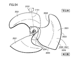
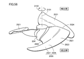
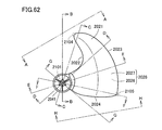
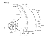
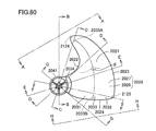
- FIG. 53 It is a perspective view which shows the circulator provided with the propeller fan in Embodiment B1 of this invention. It is the perspective view which looked at the propeller fan in Embodiment B1 of this invention from the suction side. It is another perspective view which looked at the propeller fan in FIG. 53 from the suction side. It is the top view which looked at the propeller fan in FIG. 53 from the suction side. It is the perspective view which looked at the propeller fan in FIG. 53 from the ejection side. It is the top view which looked at the propeller fan in FIG. 53 from the ejection side. It is a side view which shows the propeller fan in FIG. It is another side view which shows the propeller fan in FIG. FIG. 54 is still another side view showing the propeller fan in FIG.
- FIG. 54 is still another side view showing the propeller fan in FIG. 53. It is the top view which expanded the propeller fan in FIG. 55 partially.
- FIG. 63 is a side view showing a propeller fan viewed from the AA line in FIG. 62.
- FIG. 63 is a cross-sectional view showing the propeller fan along the line BB in FIG. 62.
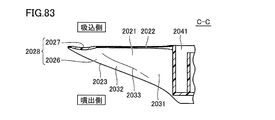
- FIG. 63 is a cross-sectional view showing the propeller fan along the line CC in FIG. 62.
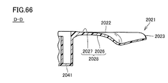
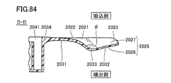
- FIG. 63 is a cross-sectional view showing the propeller fan along the line DD in FIG. 62.
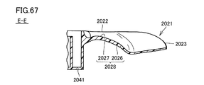
- FIG. 63 is a cross-sectional view showing the propeller fan along the line EE in FIG. 62.
- FIG. 63 is a cross-sectional view showing the propeller fan along the line FF in FIG. 62.
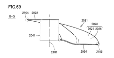
- FIG. 63 is a cross-sectional view showing the propeller fan along the line GG in FIG. 62.
- FIG. 63 is a side view showing a propeller fan viewed from the line HH in FIG. 62. It is a side view which shows the 1st modification of the propeller fan in FIG. It is a side view which shows the 2nd modification of the propeller fan in FIG. It is a side view which shows the propeller fan in a comparative example.
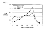
- FIG. 74 is a graph showing the relationship between the distance from the center of rotation and the wind speed in the propeller fan in the embodiment B1 in FIG. 53 and the propeller fan in the comparative example in FIG.
- FIG. 74 is a graph showing the relationship between the rotational speed and the air volume in the propeller fan in the embodiment B1 in FIG. 53, the propeller fan in the first modified example in FIG. 71, and the propeller fan in the comparative example in FIG. 73.
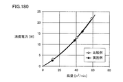
- FIG. 74 is a graph showing the relationship between air volume and power consumption in the propeller fan in Embodiment B1 in FIG. 53, the propeller fan in the first modification in FIG. 71, and the propeller fan in the comparative example in FIG. 73.
- FIG. 74 is a graph showing the relationship between the air volume and noise in the propeller fan in Embodiment B1 in FIG. 53, the propeller fan in the first modification in FIG.
- FIG. 81 is a side view showing the propeller fan viewed from the AA line in FIG. 80.
- FIG. 81 is a cross-sectional view showing the propeller fan along the line BB in FIG. 80.
- FIG. 81 is a cross-sectional view showing the propeller fan along the line CC in FIG. 80.
- FIG. 81 is a cross-sectional view showing the propeller fan along the line DD in FIG. 80.
- FIG. 81 is a cross-sectional view showing the propeller fan along the line EE in FIG. 80.
- FIG. 81 is a cross-sectional view showing the propeller fan along the line FF in FIG. 80.
- FIG. 81 is a cross-sectional view showing the propeller fan along the line GG in FIG. 80.
- FIG. 81 is a side view showing the propeller fan viewed from the HH line in FIG. 80.
- FIG. 79 is a cross-sectional view along the line LXXIX-LXXXIX in FIG. 78.
- FIG. 79 is a cross-sectional view along the line XC-XC in FIG. 78.
- FIG. 104 It is a figure which shows typically the state of the wind obtained when the propeller fan in Embodiment B3 of this invention is rotated at high speed. It is a side view which shows the electric fan provided with the propeller fan in Embodiment B4 of this invention. It is the perspective view which looked at the propeller fan in Embodiment B4 of this invention from the suction side. It is the perspective view which looked at the propeller fan in FIG. 104 from the ejection side. It is the top view which looked at the propeller fan in FIG. 104 from the suction side. It is the top view which looked at the propeller fan in FIG. 104 from the ejection side. It is a side view which shows the propeller fan in FIG.
- FIG. 111 It is sectional drawing which shows the metal mold
- 118 is a graph showing the relationship between the rotation speed and the air volume in the propeller fan in the second modified example in FIG. 118 and the propeller fan in the first comparative example in FIG. 120. 118 is a graph showing the relationship between the air volume and power consumption in the propeller fan in the second modified example in FIG.
- 118 is a graph showing the relationship between air volume and noise in the propeller fan in the second modified example in FIG. 118 and the propeller fan in the first comparative example in FIG. 120.
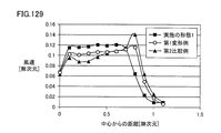
- 118 is a graph showing the relationship between the distance from the center of rotation and the wind speed in the propeller fan in the second modified example in FIG. 118 and the propeller fan in the first comparative example in FIG. 120.
- 116 is a graph showing the relationship between the rotational speed and the air volume in the propeller fan in the embodiment C1 in FIG. 116, the propeller fan in the first modification in FIG. 117, and the propeller fan in the second comparative example in FIG.
- 116 is a graph showing the relationship between air volume and power consumption in the propeller fan in the embodiment C1 in FIG. 116, the propeller fan in the first modification in FIG. 117, and the propeller fan in the second comparative example in FIG. 116 is a graph showing the relationship between the air volume and noise in the propeller fan in the embodiment C1 in FIG. 116, the propeller fan in the first modification in FIG. 117, and the propeller fan in the second comparative example in FIG. 116 is a graph showing the relationship between the distance from the rotation center and the wind speed in the propeller fan in the embodiment C1 in FIG. 116, the propeller fan in the first modified example in FIG. 117, and the propeller fan in the second comparative example in FIG. It is.
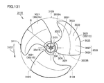
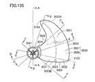
- FIG. 132 is a plan view partially showing the propeller fan in FIG. 131.
- FIG. 132 is another plan view partially showing the propeller fan in FIG. 131.
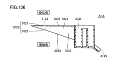
- FIG. 136 is a cross-sectional view showing the propeller fan along the line AA in FIG. 135.
- FIG. 136 is a cross-sectional view showing the propeller fan along the line BB in FIG. 135.
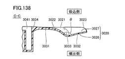
- FIG. 136 is a cross-sectional view showing the propeller fan along the line CC in FIG. 135.
- FIG. 136 is a cross-sectional view showing the propeller fan along the line DD in FIG. 135.
- FIG. 136 is a cross-sectional view showing the propeller fan along the line EE in FIG. 135.
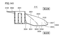
- FIG. 136 is a cross-sectional view showing the propeller fan along the line FF in FIG. 135.
- FIG. 135 is a cross sectional view taken along the line CXLII-CXLII in FIG. 134.
- FIG. 135 is a cross sectional view taken along a line CXLIII-CXLIII in FIG. 134.
- Embodiment D1 of the present invention It is a partially exploded side view of the electric fan in Embodiment D1 of the present invention. It is the perspective view seen from the back side of the propeller fan in Embodiment D1 of this invention. It is the perspective view seen from the front side of the propeller fan in Embodiment D1 of this invention. It is a rear view of the propeller fan in Embodiment D1 of this invention. It is a front view of the propeller fan in Embodiment D1 of this invention. It is a side view of the propeller fan in Embodiment D1 of this invention. It is a conceptual diagram which shows the flow of the wind obtained when a propeller fan is rotated at low speed in the electric fan in Embodiment D1 of this invention.
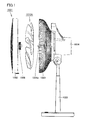
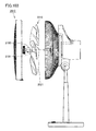
- FIG. 1 is a partially exploded side view of the electric fan according to Embodiment A1 of the present invention. First, with reference to this FIG. 1, the electric fan 1001 as a fluid feeder in this Embodiment is demonstrated.
- the electric fan 1001 mainly includes a front guard 1002, a rear guard 1003, a main body 1004, a stand 1005, and a propeller fan 1010A.
- the main body 1004 is supported by a stand 1005, and a drive motor (not shown) is accommodated therein.
- a rotation shaft 1004a of the drive motor is located on the front surface of the main body portion 1004, and a boss hub portion 1011 (see FIG. 2 and the like) as a rotation shaft portion of a propeller fan 1010A described later is screwed to the rotation shaft 1004a. It is fixed using a cap 1006.
- the front guard 1002 and the rear guard 1003 are provided so as to surround the propeller fan 1010A fixed to the main body 1004. More specifically, the rear guard 1003 is fixed to the main body 1004 so as to cover the back side of the propeller fan 1010A, and the front guard 1002 is fixed to the rear guard 1003 so as to cover the front side of the propeller fan 1010A.
- the stand 1005 is provided to place the electric fan 1001 on the floor or the like, and supports the main body 1004. In addition, at a predetermined position of the stand 1005, an operation unit (not shown) for turning on / off the electric fan 1001, switching the operation state, and the like is provided.
- main body 1004 and the stand 1005 are preferably connected so that the main body 1004 can swing in a horizontal plane and a vertical plane so that the electric fan 1001 has a neck swing function. .
- the stand 1005 is configured to be stretchable along the vertical direction so that the electric fan 1001 has a height adjusting function.
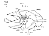
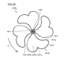
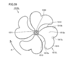
- FIGS. 2 and 3 are perspective views of the propeller fan according to the present embodiment as viewed from the rear side and the front side
- FIGS. 4 to 6 are a rear view, a front view, and a side view of the propeller fan according to the present embodiment.
- FIG. Next, the basic structure of propeller fan 1010A in the present embodiment will be described with reference to FIGS.
- the propeller fan 1010A includes the above-described boss hub portion 1011 as a rotating shaft portion and a plurality of smoothly bent plate-like blades 1012A.
- the boss hub portion 1011 has a bottomed substantially cylindrical shape, and each of the plurality of blades 1012A is directed radially outward from the outer peripheral surface of the boss hub portion 1011 so as to be aligned along the circumferential direction of the boss hub portion 1011. Projecting.
- Propeller fan 1010A in the present embodiment has seven blades, and is a resin molding in which boss hub portion 1011 and seven blades 1012A are integrally molded with a synthetic resin such as AS (acrylonitrile-styrene) resin. It is composed of products.
- AS acrylonitrile-styrene
- the boss hub portion 1011 rotates in the direction of arrow A shown in the figure with the virtual center axis 1020 as the center of rotation when driven by the drive motor described above.
- the entire propeller fan 1010A rotates in the direction of arrow A shown in the drawing with the central axis 1020 described above as the center of rotation, and a plurality of blades 1012A provided side by side along the circumferential direction of the boss hub portion 1011. Will also rotate around the central axis 1020 described above.
- the plurality of blades 1012A are arranged at equal intervals so as to be separated from each other along the rotation direction, and each of the plurality of blades 1012A has the same shape. . Therefore, when one of the blades 1012A is rotated about the central axis 1020 as the rotation center, the shape of the blade 1012A matches the shape of another blade 1012A.
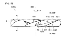
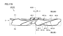
- the blades 1012A extend along the rotation direction of the propeller fan 1010A, the front edge portion 1013 located on the front side in the rotation direction of the propeller fan 1010A, the rear edge portion 1014 located on the rear side in the rotation direction of the propeller fan 1010A, and the propeller fan 1010A. And an outer edge portion 1015. That is, in a state in which propeller fan 1010A is viewed in plan along central axis 1020, the outer shape of blade 1012A is the front edge portion 1013, rear edge portion 1014, and outer edge portion 1015 except for the portion connected to boss hub portion 1011. It will be prescribed by.
- the front edge portion 1013 and the rear edge portion 1014 extend outward in the radial direction from the boss hub portion 1011.
- both the front edge portion 1013 and the rear edge portion 1014 are gradually positioned on the front side in the rotational direction from the radially inner side toward the outer side. As a whole, it has a generally arcuate shape.
- the leading edge 1013 is A portion having a certain height is included between the inner end and a position spaced radially outward.
- the front edge portion 1013 A portion closer to the radially inner side connected to the boss hub portion 1011 extends so as to overlap the suction side end surface.
- the portion of the front edge portion 1013 closer to the outer side in the radial direction does not overlap the suction side end surface, and is provided closer to the ejection side than the suction side end surface as a whole.
- the radial direction including the outer end of the trailing edge 1014 is configured such that its height increases from the radially inner side toward the radially outer side.
- the trailing edge 1014 is In other words, it is configured to move away from the ejection side end face as it goes radially outward. That is, the portion of the rear edge portion 1014 closer to the outside in the radial direction does not overlap the ejection side end surface, and is provided closer to the suction side than the ejection side end surface as a whole.
- the wing 1012A is configured so that the width along the rotation direction is reduced, and the front edge portion 1013 and the rear edge portion are formed.
- the blades 1012A are configured so that their widths along the rotation direction are increased.
- the outer end located on the radially outer side of the front edge portion 1013 is connected to the front end 1015a in the rotational direction of the outer edge portion 1015, and the outer end located on the radially outer side of the rear edge portion 1014 is rotated by the outer edge portion 1015. It is connected to the rear end 1015b in the direction. That is, the outer edge portion 1015 is configured to connect the outer end of the front edge portion 1013 and the outer end of the rear edge portion 1014 along the rotational direction, and has a generally arcuate shape as a whole.
- the outer edge portion 1015 is positioned away from the suction side end surface along the direction in which the central axis 1020 extends, and the entire outer edge portion 1015 extends from the ejection side end surface along the direction in which the central axis 1020 extends. They are located apart. That is, the outer edge portion 1015 does not overlap the suction side end surface and the ejection side end surface at any position, and is provided closer to the inside than the suction side end surface and the ejection side end surface as a whole.
- each of the front edge portion 1013 and the rear edge portion 1014 is formed to have a generally arcuate shape, thereby forming a smooth shape.
- the outer edge portion 1015 is formed to have a generally arcuate shape so as to have a smooth shape. For this reason, the front end 1015a and the rear end 1015b of the outer edge portion 1015 described above have curvatures that are maximal at least in the vicinity thereof.
- the front end 1015a of the outer edge portion 1015 described above has a sickle-pointed shape in a state in which the propeller fan 1010A is viewed in plan along the central axis 1020.
- the sickle-shaped front end 1015a is disposed at the most forward position of the wing 1012A in the rotation direction.
- the front edge portion 1013 and the outer edge portion 1015 located in the vicinity of the front end 1015a are portions located forward in the rotation direction, and thus correspond to blade tip portions where blade tip vortices are generated.
- the blade 1012A is formed with a blade surface for blowing air as the propeller fan 1010A rotates (that is, sending air from the suction side to the ejection side).
- the blade surface includes a negative pressure surface 1012a corresponding to the back surface of the blade 1012A located on the suction side and a positive pressure surface 1012b corresponding to the front surface of the blade 1012A located on the ejection side, both of which are described above. It is formed in a region surrounded by the edge portion 1013, the rear edge portion 1014, and the outer edge portion 1015.
- the negative pressure surface 1012a and the positive pressure surface 1012b which are blade surfaces, both incline from the ejection side to the suction side of the propeller fan 1010A along the rotation direction of the propeller fan 1010A from the rear edge portion 1014 toward the front edge portion 1013. It is composed of a curved surface.
- the blade 1012A has a blade inner region 1018a and a blade outer region 1018b having mutually different blade surface shapes (see FIG. 7).
- the blade inner region 1018a corresponds to a region located on the boss hub portion 1011 side of the blade 1012A
- the blade outer region 1018b corresponds to a region located on the outer edge portion 1015 side of the blade 1012A.
- the blade 1012A includes a blade inner region 1018a located on the boss hub portion 1011 side, a blade outer region 1018b located on the outer edge portion 1015 side, and a blade inner region such that the negative pressure surface 1012a side is concave and the positive pressure surface 1012b side is convex.
- the connecting portion 1016 has a surface curvature that is maximal in the vicinity thereof, and appears as a curved concave groove portion on the suction surface 1012a, and as a protrusion protruding in a curved shape on the pressure surface 1012b. Appears.
- the connecting portion 1016 is provided substantially along the rotation direction, and extends from a position in the vicinity of the front end 1015a of the outer edge portion 1015 toward a position in the middle of the rear edge portion 1014 in the radial direction.
- the blade 1012A when viewed along the rotation direction of the propeller fan 1010A, becomes thicker from the front edge portion 1013 and the rear edge portion 1014 toward the blade center and the leading edge than the blade center.
- An airfoil shape having a maximum thickness is formed at a position close to the portion 1013 side.
- the outer edge portion 1015 of the blade 1012A is positioned on the front outer edge portion 1017b (see FIG. 7) located on the front edge portion 1013 side and on the rear edge portion 1014 side.
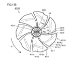
- FIG. 7 is an enlarged rear view showing the shape of the blades of the propeller fan in the present embodiment.
- the outer edge portion 1015 of the wing 1012 ⁇ / b> A is formed with a connection portion 1017 a having a shape that is recessed toward the central axis 1020 side.
- the connection portion 1017a is formed at a position midway between the front end 1015a and the rear end 1015b of the outer edge portion 1015.
- the outer edge portion 1015 of the wing 1012A has a front outer edge portion 1017b positioned on the front end 1015a side of the outer edge portion 1015 and a rear end 1015b side of the outer edge portion 1015.
- a rear outer edge portion 1017c is provided.
- the connecting portion 1017a is preferably formed so as to have a smoothly curved shape as shown in the figure, but this is not necessarily a curved shape and may be a bent shape. Further, in the present embodiment, since the connection portion 1017a is formed so as to be recessed relatively shallowly, the connection portion 1017a has a substantially obtuse angle shape.
- connection portion 1017a is formed is not particularly limited as long as it is a position on the outer edge portion 1015.
- the connection portion 1017a is located near the rear end 1015b of the outer edge portion 1015. Is formed. Therefore, in the present embodiment, the width along the rotation direction of the front outer edge portion 1017b is formed larger than the width along the rotation direction of the rear outer edge portion 1017c.
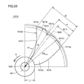
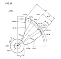
- a bisector 1030 having an angle formed by a line segment connecting the rear end 1015b of the outer edge 1015 and the central axis 1020 is drawn, the front end 1015a and the rear along the direction perpendicular to the bisector 1030 are drawn.
- the distance between the end 1015b is W
- the distance between the rear end 1015b along the direction perpendicular to the bisector 1030 and the most radially inner point of the connecting portion 1017a is w.
- the distance W and the distance w satisfy the condition of W / 2> w.
- the maximum radius R2 max from the central axis 1020 of 1017c satisfies the condition of R1 max > R2 max .
- the central axis 1020 at the point located on the innermost radial direction of the connecting portion 1017a in a state where the blade 1012A is viewed in plan along the central axis 1020. If the radius from is R, the radius R and the maximum radius R2 max satisfy the condition of R ⁇ R2 max .
- the wind speed distribution in the radial direction can be made more uniform, and the unevenness of the wind speed can be suppressed, so that the wind with good wind perception can be obtained.
- the outer edge is compared with the case where the recessed connection portion 1017a is not formed on the outer edge portion 1015.
- the blade area decreases in the vicinity of the portion 1015 (that is, the portion closer to the outside in the radial direction). Therefore, the wind speed that increases in proportion to the outer side in the radial direction is moderated in the portion closer to the outer edge portion 1015, and the wind speed generated in the portion closer to the inner side in the radial direction is closer to the outer edge portion 1015.
- the wind speed of the wind generated in the part approaches, and the wind speed distribution in the radial direction becomes more uniform. Therefore, unevenness in the wind speed can be suppressed, and a wind with good wind perception can be obtained.
- the wing 1012A having the above-described configuration, it is possible to generate a wind with good wind perception, in which the pressure fluctuation included in the wind generated in the radially outer portion is reduced.
- the present embodiment since it has a wing shape in which the outer edge portion 1015 is formed with a hollow-shaped connection portion 1017a, it is between the front outer edge portion 1017b and the rear outer edge portion 1017c of one wing 1012A.
- a relatively small space that is, a space where the depression-shaped connecting portion 1017a is located
- the space exists as a space that does not generate wind in the wing 1012A.
- the front outer edge portion 1017b and the rear outer edge portion 1017c provided on one wing 1012A play an approximate role as if air is blown by two wings. It is possible to generate a breeze with a small pressure fluctuation.
- the details of the effect will be more specifically referred to in the embodiment A2 of the present invention described later.
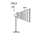
- FIG. 8 is a conceptual diagram showing the flow of wind obtained when the propeller fan is rotated at a low speed in the electric fan according to the present embodiment
- FIG. 9 is a diagram of the wind obtained when the propeller fan is rotated at a low speed. It is a figure which shows a state typically.
- FIG. 10 is a conceptual diagram showing the flow of wind obtained when the propeller fan is rotated at a high speed in the electric fan according to the present embodiment
- FIG. 11 is obtained when the propeller fan is rotated at a high speed. It is a figure which shows the state of a wind typically.
- the trajectory of the wing tip vortex generated in the vicinity of the front end 1015a of the outer edge portion 1015 is schematically shown by a broken line.
- the trajectory of the wind generated at a position near the outer edge portion 1015 of the wing 1012A is schematically shown by a thick line.
- the recessed connection portion 1017a is formed at a position on the outer edge portion 1015 of the wing 1012A.
- the position on the outer edge portion 1015 corresponds to a position along the streamline of the blade tip vortex flowing on the blade surface on the downstream side of the blade tip portion including the front end 1015a of the outer edge portion 1015.
- the wind generated by the blades 1012A converges in front of the electric fan 1001, and the wind 1300 that travels far and has high straightness can be blown. Therefore, it is possible to blow air efficiently, and the generation of noise can be suppressed by increasing the straightness of the wind.
- the propeller fan 1010A and the electric fan 1001 provided with the propeller fan 1010A in this embodiment it is possible to send out a wind having a small variation in the pressure of the generated wind and good wind perception, and to reduce noise. It becomes possible to plan.
- the propeller fan 1010A according to the present embodiment can provide the following effects.
- the portion excluding the portion on the outer side in the radial direction of the front edge portion 1013 is configured to be located on the suction side end surface. Therefore, it is possible to increase the blowing capacity in the portion closer to the radially inner side of the blade 1012A, and it is possible to increase the wind speed of the wind generated in the portion closer to the radially inner side, which occurs in the portion closer to the outer edge portion 1015. This approaches the wind speed of the wind, and the wind speed distribution in the radial direction becomes more uniform. Therefore, unevenness in the wind speed can be suppressed, and a wind with good wind perception can be obtained.
- the rear edge portion 1014 is configured to be separated from the ejection side end surface as it goes outward in the radial direction. Therefore, the wind speed that increases in proportion to the outer side in the radial direction is moderated in the portion closer to the outer edge portion 1015, and the wind speed generated in the portion closer to the inner side in the radial direction is closer to the outer edge portion 1015.
- the wind speed of the wind generated in the part approaches, and the wind speed distribution in the radial direction becomes more uniform. Therefore, unevenness in the wind speed can be suppressed, and a wind with good wind perception can be obtained.
- a connecting portion 1016 is provided to bend and connect these at the boundary between the blade inner region 1018a and the blade outer region 1018b. For this reason, a horseshoe vortex is generated on the connecting portion 1016, and the mainshoe vortex suppresses separation of the mainstream flowing on the wing surface, so that noise is reduced and blowing capacity is increased. Become. Further, as described above, in the present embodiment, since the connecting portion 1016 is provided substantially along the rotation direction, the wing tip vortex is also connected in addition to the horseshoe vortex generated on the connecting portion 1016. It is held on the portion 1016, and the mainstream separation can be further suppressed. In addition, the connection part 1016 does not need to be curved, for example, may be bent.
- the entire outer edge portion 1015 is positioned away from the suction side end surface along the direction in which the central axis 1020 extends, and the entire outer edge portion 1015 is the central axis. It is located away from the ejection side end face along the direction in which 1020 extends. For this reason, the overall thickness of the blade 1012A of the propeller fan 1010A in the direction along the central axis 1020 is greatly reduced in the radially outer portion, so that the gap between the front guard 1002 and the rear guard 1003 described above is reduced. A large distance can be secured in this portion. Therefore, it is possible to suppress the occurrence of finger pinching or the like in the electric fan 1001, and it is possible to improve safety.
- the first verification test a plurality of samples having different positions along the rotational direction and the radial direction of the connecting portion provided on the outer edge portion are prepared, and each sample is rotated based on this, and the air volume obtained at that time And the pressure fluctuation contained in the obtained wind was measured.
- the wing inner region and the wing outer region are not configured to have different wing surface shapes, but the entire wing surface is configured to have a single wing surface shape. .
- the position where the connecting portion is provided is determined in advance, and the parallelogram having the connecting portion as one vertex is a portion near the rear end of the blade and the trailing edge of the blade. I drew it on the part near the outer edge of the part, and decided to cut out a part of the wing in a form that was almost along the parallelogram.
- the outer edge is formed so that both the front outer edge portion and the rear outer edge portion formed using the connection portion and the connection portion as a boundary have a smooth shape. The part was curved appropriately.
- both are located at a position 30 mm away on the ejection side along the central axis of the propeller fan, and the distance along the radial direction from the rotation center of the propeller fan is 70% of the maximum radius of the outer edge portion.
- the measurement was performed at a position corresponding to the position.
- the position corresponding to the position where the distance along the radial direction from the rotation center of the propeller fan is 70% of the maximum radius of the outer edge is generally the position where the wind speed is the largest, and therefore the position where the pressure fluctuation is most likely to occur. is there.
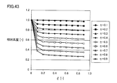
- FIG. 12 is a graph showing the relationship between the blade shape and the relative airflow obtained in the first verification test.
- the horizontal axis represents the position along the rotation direction of the connecting portion
- the vertical axis represents the relative air volume.
- ⁇ shown on the horizontal axis is a value expressed by w / W using the above-described distance W and distance w
- ⁇ is the above-mentioned maximum radius R1 max , radius R, and radius r of the boss hub (see FIG. 7), (R1 max -R) / (R1 max -r).
- the relative air volume shown on the vertical axis is a value obtained by dividing the air volume measured in each sample by the air volume in a propeller fan in which no hollow connection portion is formed on the outer edge.
- the air volume tends to gradually decrease as the connecting portion moves from the rear end to the front end of the outer edge.
- the connecting portion is close to the front end of the outer edge portion along the rotation direction, there is no tendency for the air volume to further decrease.
- the air volume tends to gradually decrease as the connecting portion moves from the position near the outer edge portion toward the position near the rotation center along the radial direction.
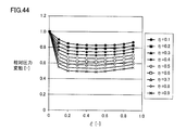
- FIG. 13 is a graph showing the relationship between the blade shape and the relative pressure fluctuation obtained in the first verification test.
- the horizontal axis represents the position along the rotation direction of the connecting portion
- the vertical axis represents the relative pressure fluctuation.
- the relative pressure fluctuation shown on the vertical axis is obtained by dividing the maximum value of the pressure difference measured in each sample by the maximum value of the pressure difference in the propeller fan in which no hollow connection portion is formed on the outer edge. It is the value.
- the pressure variation tends to gradually decrease as the connecting portion moves from the position near the rear end toward the position near the front end along the rotation direction. Further, it is understood that the pressure fluctuation tends to further decrease as the connecting portion moves from the position near the outer edge portion toward the position near the rotation center along the radial direction.
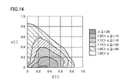
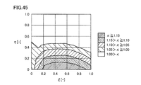
- FIG. 14 is a contour diagram showing the relationship between the wing shape and the comfort index obtained in the first verification test.
- the contour diagram represents the result of the first verification test as the fan performance including the comfort index ⁇ based on the results shown in FIGS. 12 and 13 described above.
- the comfort index ⁇ is calculated by dividing the relative air volume shown in FIG. 12 by the relative pressure fluctuation shown in FIG. 13, and the higher this value, the higher the comfort.
- the horizontal axis represents the position along the rotation direction of the connecting portion
- the vertical axis represents the position along the radial direction of the connecting portion.
- the comfort index ⁇ is reliably improved by 10% or more as compared with the propeller fan in which the concave connection portion is not formed.
- the propeller fan according to the comparative example 1 has a single blade surface shape in which a hollow connection portion is not formed at the outer edge portion. Are different from each other in that the front edge portion is formed so as to be inclined substantially monotonously along the radial direction. In other respects, the front edge portion has a common shape. It was.
- the wind speed is measured at a position 30 mm away on the ejection side along the central axis of the propeller fan, and the distance from the central axis is the outer edge in order to grasp the radial distribution.
- the center axis is arranged in increments of 0.1 times up to a position corresponding to a position that is 1.1 times the maximum radius.
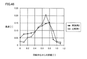
- FIG. 15 is a graph showing the relationship between the distance from the rotation center of the propeller fan according to Example 1 and Comparative Example 1 and the wind speed obtained in the second verification test.
- the horizontal axis represents the distance from the center of rotation
- the vertical axis represents the wind speed.
- the distance from the rotation center is represented by a dimensionless value where the position corresponding to the rotation center is 0 and the position corresponding to the outer edge is 1, and the vertical axis indicates the first embodiment.
- the air volumes are matched, and the wind speed is represented by a dimensionless value obtained by dividing the measured value of each wind speed by the air volume.
- the wind speed is small on the radially inner side, and gradually increases toward the radially outer side, which is 0.7 times the maximum radius of the outer edge portion. At the position, the wind speed shows the maximum value, and the wind speed tends to gradually decrease toward the outer side in the radial direction.
- the wind speed is larger on the inner side in the radial direction than that in Comparative Example 1, and there is almost no change in the wind speed toward the outer side in the radial direction. There is a tendency that the wind speed begins to decrease at a position of 7 times and gradually decreases toward the outside in the radial direction.
- the maximum value of the wind speed was lower in Example 1 than in Comparative Example 1.
- the wind speed distribution along the radial direction is greatly uniformed, and it is possible to suppress the unevenness of the wind speed and the wind with good wind perception. It was confirmed that it can be.
- FIG. 16 is a schematic sectional view showing a propeller fan molding die in the present embodiment.
- a propeller fan molding die 1100 according to the present embodiment will be described with reference to FIG.
- propeller fan 1010A in the present embodiment is formed of a resin molded product.
- a molding die 1100 for injection molding as shown in FIG. 16 is used.
- the molding die 1100 includes a fixed side die 1101 and a movable side die 1102.
- the fixed mold 1101 and the movable mold 1102 define a cavity 1103 having substantially the same shape as the propeller fan 1010A and into which a fluid resin is injected.
- the molding die 1100 may be provided with a heater (not shown) for improving the fluidity of the resin injected into the cavity 1103.
- a heater for improving the fluidity of the resin injected into the cavity 1103.
- the installation of such a heater is particularly effective when, for example, a synthetic resin with increased strength such as an AS resin containing glass fiber is used.
- the surface on the positive pressure surface 1012b side of the propeller fan 1010A is molded by the fixed die 1101, and the surface on the negative pressure surface 1012a side is molded by the movable die 1102.
- the surface on the negative pressure surface 1012a side of the propeller fan 1010A may be formed by the fixed mold 1101 and the surface on the positive pressure surface 1012b side of the propeller fan 1010A may be formed by the movable mold 1102.
- a propeller fan that uses metal as a material and is integrally formed by drawing by press working.
- a thin metal plate is generally used because it is difficult to draw with a thick metal plate and the mass becomes heavy. In this case, it is difficult to maintain strength (rigidity) with a large propeller fan.
- a part that uses a part called a spider formed of a metal plate thicker than the wing part and fixes the wing part to the rotating shaft but there is a problem that the mass becomes heavy and the fan balance is also deteriorated.
- a thin metal plate having a certain thickness is used, there is a problem that the cross-sectional shape of the wing cannot be a wing shape.
- a boss hub provided for inserting the rotating shaft 1004a in order to further reduce noise as a countermeasure against cocking noise unique to the DC motor.
- a cylindrical rubber boss may be insert-molded in the shaft hole of the portion 1011. In that case, a rubber boss as an insert part may be installed in a mold for molding the surface on the suction surface 1012a side of the propeller fan 1010A prior to injection molding.
- propeller fans 1010B to 1010K according to the first to tenth modifications based on the above-described embodiment will be described.
- Propeller fans 1010B to 1010K according to the first to tenth modifications shown below are basically in the shape and position of propeller fan 1010A in the above-described embodiment and connecting portion 1017a provided on outer edge portion 1015. It is different.
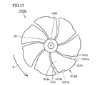
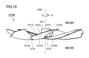
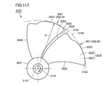
- FIG. 17 and 18 are a rear view and a side view of the propeller fan according to the first modification
- FIG. 19 is an enlarged rear view showing the shape of the blades of the propeller fan according to the first modification.
- propeller fan 1010B has a blade surface shape in which the blade inner region and the blade outer region are different from propeller fan 1010A in the present embodiment described above.
- the entire blade surface is configured to have a single blade surface shape without being configured as described above, and the entire outer edge portion 1015 extends from the suction side end surface along the direction in which the central axis 1020 extends. It is different in that it is not spaced apart, and other configurations have the same configuration as propeller fan 1010A in the present embodiment described above.
- the outer edge portion 1015 is provided with a recessed connection portion 1017a, so that the outer edge portion 1015 of the wing 1012B has a front outer edge portion 1017b positioned on the front end 1015a side of the outer edge portion 1015 and the outer edge portion 1015B.
- a rear outer edge portion 1017c located on the rear end 1015b side of the outer edge portion 1015 is provided.
- the connection portion 1017a is formed so as to be recessed relatively shallowly, and thus the connection portion 1017a has a substantially obtuse angle shape.
- the distance W and the distance w satisfy the condition of W / 2> w
- the maximum radius R1 max and the maximum radius R2 max are , R1 max > R2 max is satisfied, and the radius R and the maximum radius R2 max satisfy the condition of R ⁇ R2 max .
- (Second modification) 20 and 21 are a rear view of a propeller fan according to a second modification and an enlarged rear view showing the shape of a blade.
- the propeller fan 1010C according to the second modified example is only in the shape of the propeller fan 1010B according to the first modified example described above and the recessed connection portion 1017a provided in the outer edge portion 1015.
- the other configurations are the same as those of the propeller fan 1010B according to the first modification described above.
- connection portion 1017a provided on outer edge portion 1015 is formed to be recessed relatively deep, and connection portion 1017a has a substantially acute angle shape.
- the distance W and the distance w satisfy the condition of W / 2> w
- the maximum radius R1 max and the maximum radius R2 max are , R1 max > R2 max is satisfied, and the radius R and the maximum radius R2 max satisfy the condition of R ⁇ R2 max .
- the same effect as that obtained in the first modified example described above can be obtained, and the pressure fluctuation of the generated wind is small and it is possible to send out a wind with good wind perception. At the same time, noise is reduced.
- the air velocity distribution along the radial direction is made more uniform by the size of the recessed connection portion 1017a provided in the outer edge portion 1015 than in the first modification described above. It can be realized effectively.
- (Third Modification) 22 and 23 are a rear view of a propeller fan according to a third modification and an enlarged rear view showing the shape of a blade.
- the propeller fan 1010D according to the third modified example is only in the shape of the propeller fan 1010B according to the first modified example described above and the recessed connecting portion 1017a provided in the outer edge portion 1015.
- the other configurations are the same as those of the propeller fan 1010B according to the first modification described above.
- connection portion 1017a provided on outer edge portion 1015 is formed to be recessed relatively deep, and connection portion 1017a has a substantially obtuse angle shape.
- the distance W and the distance w satisfy the condition of W / 2> w
- the maximum radius R1 max and the maximum radius R2 max are , R1 max > R2 max is satisfied, and the radius R and the maximum radius R2 max satisfy the condition of R ⁇ R2 max .
- the same effect as that obtained in the first modified example described above can be obtained, and the pressure fluctuation of the generated wind is small and it is possible to send out a wind with good wind perception. At the same time, noise is reduced.
- the air velocity distribution along the radial direction is made more uniform as the hollow connection portion 1017a provided in the outer edge portion 1015 is larger than the first modified example described above. It can be realized effectively.
- (Fourth modification) 24 and 25 are a rear view of a propeller fan according to a fourth modification and an enlarged rear view showing the shape of a blade.
- the propeller fan 1010E according to the fourth modified example is only in the shape of the propeller fan 1010B according to the first modified example described above and the connection portion 1017a having a hollow shape provided in the outer edge portion 1015.
- the other configurations are the same as those of the propeller fan 1010B according to the first modification described above.
- the connection portion 1017a provided on the outer edge portion 1015 is formed such that the front outer edge portion 1017b and the rear outer edge portion 1017c form a step, and the rear outer edge portion 1017c
- the maximum radius R2 max is configured to be smaller than the maximum radius R1 max of the front outer edge portion 1017b.
- the distance W and the distance w satisfy the condition of W / 2> w
- the maximum radius R1 max and the maximum radius R2 max are , R1 max > R2 max
- 5th modification 26 and 27 are a rear view of a propeller fan according to a fifth modification and an enlarged rear view showing the shape of a blade.
- the propeller fan 1010F according to the fifth modified example is only in the shape of the propeller fan 1010B according to the first modified example described above and the recessed connecting portion 1017a provided in the outer edge portion 1015.
- the other configurations are the same as those of the propeller fan 1010B according to the first modification described above.
- the connection portion 1017a provided on the outer edge portion 1015 is formed such that a front outer edge portion 1017b and a rear outer edge portion 1017c form a step, and the rear outer edge portion 1017c
- the maximum radius R2 max is configured to be significantly smaller than the maximum radius R1 max of the front outer edge portion 1017b.
- the distance W and the distance w satisfy the condition of W / 2> w
- the maximum radius R1 max and the maximum radius R2 max are , R1 max > R2 max is satisfied, and the radius R and the maximum radius R2 max satisfy the condition of R> R2 max .
- the same effect as that obtained in the first modified example described above can be obtained, and the pressure fluctuation of the generated wind is small and it is possible to send out a wind with good wind perception. At the same time, noise is reduced.
- the air velocity distribution along the radial direction is made more uniform by the size of the recessed connection portion 1017a provided in the outer edge portion 1015 than in the first modification described above. It can be realized effectively.
- (Sixth Modification) 28 and 29 are a rear view of a propeller fan according to a sixth modification and an enlarged rear view showing the shape of a blade.
- the propeller fan 1010G according to the sixth modified example is only in the shape of the propeller fan 1010B according to the first modified example described above and the recessed connecting portion 1017a provided in the outer edge portion 1015.
- the other configurations are the same as those of the propeller fan 1010B according to the first modification described above.
- the connection portion 1017a provided in the outer edge portion 1015 is formed so as to be recessed relatively deeply, and the recess-shaped connection portion 1017a has a wedge shape. It is formed in a sharp and sharp corner.
- the distance W and the distance w satisfy the condition of W / 2> w
- the maximum radius R1 max and the maximum radius R2 max are , R1 max > R2 max is satisfied, and the radius R and the maximum radius R2 max satisfy the condition of R ⁇ R2 max .
- the same effect as that obtained in the first modified example described above can be obtained, and the pressure fluctuation of the generated wind is small and it is possible to send out a wind with good wind perception. At the same time, noise is reduced.
- the front outer edge portion 1017b and the rear outer edge portion 1017c provided on one blade 1012G are blown by two blades. As a result, the effect of fulfilling the role of approximation will appear more clearly, and it will be possible to more effectively realize a wind with good wind perception with a small pressure fluctuation as a whole.
- a horseshoe vortex is generated in the portion where the connection portion 1017a is provided, and the horseshoe vortex suppresses separation of the mainstream flowing on the wing surface. Is reduced and the air blowing capability is increased. Furthermore, since the tip of the rear outer edge portion 1017c in the rotation direction is located on the front side in the rotation direction of the connection portion 1017a, the wing tip vortex in addition to the horseshoe vortex generated on the connection portion 1017a is also connected to the connection portion 1017a. It will be held at the top, and the mainstream separation can be further suppressed.
- (Seventh Modification) 30 and 31 are a rear view of a propeller fan according to a seventh modification and an enlarged rear view showing the shape of a blade.
- the propeller fan 1010H according to the seventh modified example is only at the position of the propeller fan 1010B according to the first modified example described above and the recess-shaped connecting portion 1017a provided on the outer edge portion 1015.
- the other configurations are the same as those of the propeller fan 1010B according to the first modification described above.
- connection portion 1017a is provided at the center portion along the rotation direction of outer edge portion 1015.
- the maximum radius R1 max and the maximum radius R2 max are , R1 max > R2 max is satisfied, and the radius R and the maximum radius R2 max satisfy the condition of R ⁇ R2 max .
- (Eighth modification) 32 and 33 are a rear view of a propeller fan according to an eighth modification and an enlarged rear view showing the shape of a blade.
- the propeller fan 1010I according to the eighth modified example is only at the position of the propeller fan 1010B according to the first modified example described above and the recessed connecting portion 1017a provided in the outer edge portion 1015.
- the other configurations are the same as those of the propeller fan 1010B according to the first modification described above.
- a connection portion 1017a is provided at a position near the front end 1015a of the outer edge portion 1015.
- the distance W and the distance w satisfy the condition of W / 2 ⁇ w
- the maximum radius R1 max and the maximum radius R2 max are , R1 max > R2 max is satisfied
- the radius R and the maximum radius R2 max satisfy the condition of R ⁇ R2 max .
- (Ninth Modification) 34 and 35 are a rear view of a propeller fan according to a ninth modification and an enlarged rear view showing the shape of a blade.
- the propeller fan 1010J according to the ninth modification differs from the propeller fan 1010D according to the third modification described above only in the shape of the rear outer edge portion 1017c provided on the outer edge portion 1015.
- the configuration is the same as that of the propeller fan 1010D according to the third modification described above.
- the propeller fan 1010J has a configuration in which a plurality of recesses 17c1 are further provided in a rear outer edge portion 1017c formed by providing a recess-shaped connection portion 1017a in the outer edge portion 1015. .
- the recess 17c1 has a recess shape smaller than the connection portion 1017a provided on the outer edge portion 1015. Therefore, the propeller fan 1010J according to the ninth modification example as a whole is a propeller according to the third modification example.
- the shape is similar to that of the fan 1010D.
- the number of depressions 17c1 is not limited to two as shown in the drawing, and may be one or three or more.
- the distance W and the distance w satisfy the condition of W / 2> w
- the maximum radius R1 max and the maximum radius R2 max are , R1 max > R2 max is satisfied, and the radius R and the maximum radius R2 max satisfy the condition of R ⁇ R2 max .
- FIG. 36 is an enlarged rear view showing the shape of the blades of the propeller fan according to the tenth modification. As shown in FIG. 36, in the propeller fan 1010K according to the tenth modification, each of the plurality of blades protruding from the boss hub portion 1011 toward the radially outer side has a different shape.
- each wing blade does not necessarily need to be the same, You may be comprised so that it may mutually differ.
- FIG. 37 is a perspective view seen from the back side of the propeller fan according to Embodiment A2 of the present invention
- FIGS. 38 to 40 are a rear view, a front view, and a side view of the propeller fan according to this embodiment.
- FIG. 41 is an enlarged rear view showing the shape of the blades of the propeller fan in the present embodiment.
- propeller fan 1010L according to the present embodiment will be described with reference to FIGS. Note that propeller fan 1010L in the present embodiment is mounted and used in electric fan 1001, similarly to propeller fan 1010A shown in the above-described embodiment A1.
- propeller fan 1010L in the present embodiment has four blades, and each blade 1012L has a propeller according to the first modification based on embodiment A1 described above.
- the fan 1010B has a smooth front edge portion 1013, a rear edge portion 1014, and an outer edge portion 1015 that are more curved than the blades 1012B.
- the basic structure of the blade 1012L provided in the propeller fan 1010L in the present embodiment except that the front edge portion 1013, the rear edge portion 1014, and the outer edge portion 1015 are more curved and smooth. This is the same as that of the blade 1012B provided in the propeller fan 1010B according to the first modification based on the embodiment A1 described above.
- the shape of the blade 1012L provided in the propeller fan 1010L will be described in more detail.
- the outer edge portion 1015 of the wing 1012L is formed with a connection portion 1017a having a shape that is recessed toward the central axis 1020 side.
- the connection portion 1017a is formed at a position midway between the front end 1015a and the rear end 1015b of the outer edge portion 1015.
- the outer edge portion 1015 of the wing 1012L has a front outer edge portion 1017b (see FIG. 41) positioned on the front end 1015a side of the outer edge portion 1015, and an outer edge portion 1015.
- a rear outer edge portion 1017c (see FIG. 41) located on the rear end 1015b side is provided.
- connection portion 1017a is preferably formed so as to have a smoothly curved shape as shown in the figure, but this is not necessarily a curved shape and may be a bent shape. In the present embodiment, since connection portion 1017a is formed so as to be recessed relatively deeply, connection portion 1017a has a substantially acute angle shape.
- the position where the connecting portion 1017a is formed is not particularly limited as long as it is a position on the rear end 1015b side of the center portion along the rotation direction of the outer edge portion 1015.
- the outer edge portion is not limited.
- a connection portion 1017a is formed at a position near the center portion of the positions near the rear end 1015b of 1015. Therefore, in the present embodiment, the width along the rotation direction of the front outer edge portion 1017b is formed slightly larger than the width along the rotation direction of the rear outer edge portion 1017c.
- a bisector 1030 having an angle formed by a line segment connecting the rear end 1015b of the outer edge 1015 and the central axis 1020 is drawn, the front end 1015a and the rear along the direction perpendicular to the bisector 1030 are drawn.
- the distance between the end 1015b is W
- the distance between the rear end 1015b along the direction perpendicular to the bisector 1030 and the most radially inner point of the connecting portion 1017a is w.
- the distance W and the distance w satisfy the condition of W / 2> w.
- the central axis 1020 at the point located on the innermost radial side of the connecting portion 1017a in a state where the blade 1012L is viewed in plan along the central axis 1020. If the radius from is R, the radius R and the maximum radius R2 max satisfy the condition of R ⁇ R2 max .
- the wind speed distribution in the radial direction can be made more uniform, and unevenness of the wind speed can be suppressed, so that the wind with good wind perception can be obtained.
- the said effect is the same as the effect demonstrated in Embodiment A1 mentioned above, description is not repeated about the detail.
- the present embodiment since it has a wing shape in which the outer edge portion 1015 is formed with a hollow-shaped connection portion 1017a, it is between the front outer edge portion 1017b and the rear outer edge portion 1017c of one wing 1012L.
- a relatively small space that is, a space where the depression-shaped connecting portion 1017a is located
- the space exists as a space that does not generate wind in the wing 1012L.
- the pressure difference generated in the wind generated by reducing the blade area is alleviated, and the pressure fluctuation is made smaller.
- the front outer edge portion 1017b and the rear outer edge portion 1017c provided on one wing 1012L play an approximate role as if the air is blown by two wings. It is possible to generate a breeze with a small pressure fluctuation.
- FIG. 42 is a graph conceptually showing pressure fluctuations when various propeller fans including the propeller fan in the present embodiment are rotated.
- the horizontal axis represents time
- the vertical axis represents the pressure fluctuation at a fixed point on the ejection side of the propeller fan (a position corresponding to the outer edge of the blade).
- a four-blade propeller fan in which a hollow-shaped connecting portion is formed in the outer edge portion as in the present embodiment, a four-blade propeller fan in which no hollow-shaped connecting portion is formed in the outer edge portion, and an outer edge portion The pressure fluctuation at the fixed point observed when an eight-blade propeller fan having no depression-like connecting portion is rotated is approximately as shown in FIG.
- any recess-shaped connection portion is formed in the outer edge portion.
- pressure fluctuations are suppressed compared to a four-blade propeller fan that is not made, and the peak occurs at a timing close to that of an eight-blade propeller fan that does not have a recessed connection portion formed on the outer edge.
- the propeller fan 1010L it is possible to send out a wind having a small fluctuation in the pressure of the generated wind and good wind perception, and to reduce noise.
- a third verification test that verifies the relationship between the shape of the connecting portion provided on the outer edge portion described above and the above-described effect will be described.
- the third verification test a plurality of samples having different positions along the rotation direction and the radial direction of the connecting portion provided on the outer edge portion are prepared, and the air volume obtained at that time by rotating each sample based on the samples. And the pressure fluctuation contained in the obtained wind was measured.
- the position where the connecting portion is provided is determined in advance, and a triangle with the connecting portion as one vertex is drawn on a portion near the outer edge of the wing, and the wing shape is approximately along the triangle. I decided to cut out a part.
- the outer edge is formed so that both the front outer edge portion and the rear outer edge portion formed using the connection portion and the connection portion as a boundary have a smooth shape. The part was curved appropriately.
- the distance from the center of rotation of the propeller fan along the radial direction is 70% of the maximum radius of the outer edge, both at a position 30 mm away from the propeller fan along the central axis of the propeller fan.
- the measurement was performed at a position corresponding to the position.
- the position corresponding to the position where the distance along the radial direction from the rotation center of the propeller fan is 70% of the maximum radius of the outer edge is generally the position where the wind speed is the largest, and therefore the position where the pressure fluctuation is most likely to occur. is there.
- FIG. 43 is a graph showing the relationship between the blade shape and the relative airflow obtained in the third verification test.
- the horizontal axis represents the position along the rotation direction of the connecting portion
- the vertical axis represents the relative air volume.
- ⁇ shown on the horizontal axis is a value expressed by w / W using the above-described distance W and distance w
- ⁇ is the above-mentioned maximum radius R1 max , radius R, and radius r of the boss hub (see FIG. 41)
- the value is represented by (R1 max -R) / (R1 max -r).
- the relative air volume shown on the vertical axis is a value obtained by dividing the air volume measured in each sample by the air volume in a propeller fan in which no hollow connection portion is formed on the outer edge.
- the air volume tends to gradually decrease as the connecting portion moves from the rear end to the front end of the outer edge portion along the rotational direction, and the connecting portion is positioned closer to the outer edge portion along the radial direction. It is understood that the air volume tends to gradually decrease from the position toward the center of rotation.
- FIG. 44 is a graph showing the relationship between the blade shape and the relative pressure fluctuation obtained in the third verification test.
- the horizontal axis represents the position along the rotation direction of the connecting portion
- the vertical axis represents the relative pressure fluctuation.
- the relative pressure fluctuation shown on the vertical axis is obtained by dividing the maximum value of the pressure difference measured in each sample by the maximum value of the pressure difference in the propeller fan in which no hollow connection portion is formed on the outer edge. It is the value.
- ⁇ is 0 ⁇ ⁇ 0.5 in order to prevent the decrease in the air volume while effectively suppressing the pressure fluctuation.
- the provision of the recess-shaped connecting portion near the rear end of the outer edge portion can prevent a decrease in the air volume while effectively suppressing pressure fluctuation.
- FIG. 45 is a contour diagram showing the relationship between the wing shape and the comfort index obtained in the third verification test.
- the contour diagram represents the result of the third verification test as the fan performance including the comfort index ⁇ based on the results shown in FIGS. 43 and 44 described above.
- the comfort index ⁇ is calculated by dividing the relative air volume shown in FIG. 43 by the relative pressure fluctuation shown in FIG. 44, and the higher this value, the higher the comfort.
- the horizontal axis represents the position along the rotation direction of the connecting portion
- the vertical axis represents the position along the radial direction of the connecting portion.
- the comfort index ⁇ is reliably improved by 10% or more as compared with the propeller fan in which the concave connection portion is not formed.
- the fourth verification test that verifies the relationship between the shape of the connecting portion provided on the outer edge portion described above and the above-described effect will be described.
- the above-described propeller fan according to the present embodiment is actually made as a prototype, and this is used as a second embodiment.
- the wind speed distribution in the radial direction was calculated by measuring the wind speed when the propeller fan according to Example 2 and Comparative Example 1 was rotated.
- the propeller fan according to Comparative Example 1 is the same as that described in the above-described embodiment.
- the wind speed is measured at a position 30 mm away on the ejection side along the central axis of the propeller fan, and the distance from the central axis is the outer edge in order to grasp the radial distribution.
- the center axis is arranged in increments of 0.1 times up to a position corresponding to a position that is 1.1 times the maximum radius.
- FIG. 46 is a graph showing the relationship between the distance from the rotation center of the propeller fan according to Example 2 and Comparative Example 1 and the wind speed obtained in the fourth verification test.
- the horizontal axis represents the distance from the center of rotation
- the vertical axis represents the wind speed.
- the distance from the rotation center is represented by a dimensionless value where the position corresponding to the rotation center is 0 and the position corresponding to the outer edge is 1, and the vertical axis indicates the second embodiment.
- the air volumes are matched, and the wind speed is represented by a dimensionless value obtained by dividing the measured value of each wind speed by the air volume.
- the wind speed is small on the radially inner side, and gradually increases toward the radially outer side, which is 0.7 times the maximum radius of the outer edge portion. At the position, the wind speed shows the maximum value, and the wind speed tends to gradually decrease toward the outer side in the radial direction.
- the wind speed is larger on the radially inner side than Comparative Example 1, and the wind speed gradually increases toward the radially outer side, so that the maximum radius of the outer edge portion is 0.8.
- the wind speed begins to decrease at the double position, and the wind speed tends to gradually decrease toward the outside in the radial direction.
- the maximum value of the wind speed was lower in Example 2 than in Comparative Example 1.
- the propeller fan according to Comparative Example 2 is different from the propeller fan according to Example 2 in that a recessed connection portion is not formed in the outer edge portion, and in other points And have a common shape.
- the propeller fan according to Comparative Example 3 is different from the propeller fan according to Comparative Example 2 only in that it has eight blades, and has the same shape in other points. It was.
- Measured noise was measured at a point 1 m away from the propeller fan along the central axis of the propeller fan and the ejection side.
- FIG. 47 to 49 are graphs showing noise by frequency of the propeller fans according to Example 2, Comparative Example 2, and Comparative Example 3 obtained in the fifth verification test, respectively.
- the horizontal axis represents frequency
- the vertical axis represents noise.
- the noise measured in Example 2 is very similar to the noise measured in Comparative Example 3.
- the propeller fan according to the second embodiment In consideration of the fact that the nZ sound is noise caused by the number of blades of the propeller fan as described above, in the propeller fan according to the second embodiment, the front outer edge portion and the rear outer edge provided on one blade are considered. It is thought that the part played a role similar to the case of blowing wind with two wings. That is, it is considered that the propeller fan according to Example 2 behaved as if it had eight blades.
- FIG. 50 is a side view of the propeller fan according to Embodiment A3 of the present invention.
- propeller fan 1010M according to the present embodiment will be described with reference to FIG. Note that propeller fan 1010M in the present embodiment is mounted and used in electric fan 1001, similarly to propeller fan 1010A shown in the above-described embodiment A1.
- the propeller fan 1010M in the present embodiment is configured such that the blade inner region and the blade outer region have different blade surface shapes, unlike the propeller fan 1010A in the above-described embodiment A1.
- the entire blade surface is configured to have a single blade surface shape, and the trailing edge portion 1014 is not configured to be separated from the ejection side end surface toward the radially outer side.
- the entire outer edge portion 1015 is different in that it is not positioned away from the suction side end surface along the direction in which the central axis 1020 extends.
- the above-described embodiment A1 is different.
- the distance W and the distance w satisfy the condition of W / 2> w
- the maximum radius R1 max And the maximum radius R2 max satisfy the condition of R1 max > R2 max
- the radius R and the maximum radius R2 max satisfy the condition of R ⁇ R2 max .
- FIG. 51 is a side view of the propeller fan according to Embodiment A4 of the present invention.
- propeller fan 1010N in the present embodiment will be described. Note that propeller fan 1010N in the present embodiment is mounted and used in electric fan 1001, similarly to propeller fan 1010A shown in the above-described embodiment A1.
- the propeller fan 1010N in the present embodiment has the above-mentioned suction along the direction in which the entire outer edge portion 1015 extends the central axis 1020 when compared to the propeller fan 1010A in the above-described embodiment A1. It is different only in that it is not located apart from the side end face, and the other configuration is the same as that of the propeller fan 1010A in the embodiment A1 described above.
- the distance W and the distance w satisfy the condition of W / 2> w
- the maximum radius R1 max And the maximum radius R2 max satisfy the condition of R1 max > R2 max
- the radius R and the maximum radius R2 max satisfy the condition of R ⁇ R2 max .
- the propeller fan integrally formed of a synthetic resin is exemplified as the propeller fan to which the present invention is applied.
- the scope of application of the present invention is limited to this. It is not a thing.
- the present invention may be applied to a propeller fan formed by twisting a single sheet metal, or the present invention may be applied to a propeller fan formed by an integral thin-walled object formed with a curved surface. The invention may be applied. In these cases, a structure may be adopted in which a blade is joined to a separately formed boss hub.
- the present invention is applied to a propeller fan having seven blades or four blades, but a plurality of blades other than seven or four blades are exemplified.
- the present invention may be applied to a propeller fan that includes a single blade or a propeller fan that includes one blade.
- a weight as a balancer on the opposite side of the blade with respect to the central axis.
- a fan is exemplified as a fluid feeder to which the present invention is applied, and a propeller fan mounted on a fan is illustrated as a propeller fan to which the present invention is applied.
- the present invention relates to various fluid feeding devices such as a circulator, an air conditioner, an air purifier, a humidifier, a dehumidifier, a fan heater, a cooling device or a ventilation device, and a propeller fan mounted thereon.
- various fluid feeding devices such as a circulator, an air conditioner, an air purifier, a humidifier, a dehumidifier, a fan heater, a cooling device or a ventilation device, and a propeller fan mounted thereon.
- a circulator such as a circulator, an air conditioner, an air purifier, a humidifier, a dehumidifier, a fan heater, a cooling device or a ventilation device, and a propeller fan mounted thereon.
- a circulator such as a circulator, an air conditioner, an air
- FIG. 52 is a perspective view showing a circulator including a propeller fan according to Embodiment B1 of the present invention.
- FIG. 53 is a perspective view of the propeller fan in the embodiment B1 of the present invention viewed from the suction side.
- FIG. 54 is another perspective view of the propeller fan in FIG. 53 viewed from the suction side.
- FIG. 55 is a plan view of the propeller fan in FIG. 53 as viewed from the suction side.
- FIG. 56 is a perspective view of the propeller fan in FIG. 53 as viewed from the ejection side.
- FIG. 57 is a plan view of the propeller fan in FIG. 53 as viewed from the ejection side.
- 58 to 61 are side views showing the propeller fan in FIG.
- the propeller fan 2110 in the present embodiment is a three-blade propeller fan, and is integrally formed of synthetic resin such as AS (acrylonitrile-styrene) resin.
- the propeller fan 2110 has a blade 2021A, a blade 2021B, and a blade 2021C (hereinafter, referred to as a blade 2021 unless otherwise distinguished) as a plurality of blades.
- the wing 2021 rotates around a central axis 2101 that is a virtual axis in a direction indicated by an arrow 2102 in the drawing.
- the plurality of blades 2021 rotate around the central axis 2101 to blow air from the suction side to the ejection side in the figure.
- the blades 2021A, 2021B, and 2021C are arranged at equal intervals in the circumferential direction of the rotation axis of the propeller fan 2110, that is, the central shaft 2101.
- the wing 2021A, the wing 2021B, and the wing 2021C are formed in the same shape, and when one of the wings 2021 is rotated around the central axis 2101, the shape of the wing 2021 is different from that of the wing 2021. It is formed so that the shape of the wing 2021 matches.
- the blade 2021B is disposed adjacent to the blade 2021A in the rotation direction side of the propeller fan 2110
- the blade 2021C is disposed adjacent to the blade 2021B in the rotation direction side of the propeller fan 2110.
- the blade 2021 has a front edge 2022 disposed on the rotation direction side of the propeller fan 2110, a rear edge 2024 disposed on the opposite side of the rotation direction, and a space between the front edge 2022 and the rear edge 2024. And an outer edge portion 2023 to be connected.
- the front edge portion 2022 and the rear edge portion 2024 are separated from the boss hub portion 2041 described later from the central shaft 2101. Extending from the inside in the radial direction centered on the outside.
- the front edge portion 2022 extends in the rotation direction of the propeller fan 2110 while curving from the inside in the radial direction around the center axis 2101 to the outside.
- the rear edge portion 2024 is disposed to face the front edge portion 2022 in the circumferential direction around the central axis 2101.
- the outer edge portion 2023 extends in an arc shape between the front edge portion 2022 and the rear edge portion 2024 as a whole.
- the outer edge portion 2023 extends as a whole along the circumferential direction around the central axis 2101. As shown in FIG. 55, the outer edge portion 2023 intersects with the front edge portion 2022 at the front edge side connection portion 2104 located on the most rotational direction side of the propeller fan 2110 on a line extending in the circumferential direction, and extends in the circumferential direction.
- the trailing edge side connecting portion 2105 located on the opposite side of the rotation direction of the propeller fan 2110 on the line intersects with the trailing edge portion 2024.
- FIG. 55 a circumscribed circle 2109 of a plurality of wings 2021 is shown.
- the circumscribed circle 2109 has a radius R about the central axis 2101, and a plurality of wings 2021 are inscribed inside the circumscribed circle 2109.
- the circumscribed circle 2109 is in contact with the outer edge portion 2023 of the wing 2021.
- the wing 2021 has a maximum radius R about the central axis 2101.
- the outer edge portion 2023 has a maximum diameter end portion 2111 at the boundary between a position overlapping the circumscribed circle 2109 and a position away from the circumscribed circle 2109.
- the outer edge portion 2023 is curved inward in the radial direction while extending along the circumferential direction centering on the central axis 2101 from the maximum diameter end portion 2111 toward the front edge side connection portion 2104.
- the leading edge side connecting portion 2104 and the trailing edge side connecting portion 2105 are arranged adjacent to the circumscribed circle 2109.
- the leading edge side connecting portion 2104 and the trailing edge side connecting portion 2105 are arranged on the outer peripheral side from a position away from the central axis 2101 by R / 2 (R is the maximum radius of the blade 2021 in a plan view of the propeller fan).
- R is the maximum radius of the blade 2021 in a plan view of the propeller fan).
- the front edge side connection portion 2104 has a curvature that is maximized in the vicinity where the front edge portion 2022 and the outer edge portion 2023 are connected.
- the trailing edge side connecting portion 2105 has a curvature that is maximized in the vicinity where the outer edge portion 2023 and the trailing edge portion 2024 are connected.
- the front edge portion 2022 extends while being curved between a boss hub portion 2041 and a front edge side connection portion 2104, which will be described later, in a plan view of the propeller fan 2110 shown in FIG.
- the rear edge portion 2024 extends while being curved between a boss hub portion 2041 and a rear edge side connection portion 2105 described later.
- the outer shape of the blade 2021 is configured by a front edge 2022, an outer edge 2023, and a rear edge 2024.
- the blade 2021 has a sickle-pointed shape with the front edge side connection portion 2104 where the front edge portion 2022 and the outer edge portion 2023 intersect as the tip.
- the leading edge side connection portion 2104 is positioned on the most rotational side of the propeller fan 2110 in the blade 2021.
- the blade 2021 is formed with a blade surface 2028 for blowing air as the propeller fan 2110 rotates (sending air from the suction side to the ejection side).
- the blade surface 2028 is formed on each side facing the suction side and the ejection side in the axial direction of the central shaft 2101.
- the blade surface 2028 is formed in a region surrounded by the front edge 2022, the outer edge 2023, and the rear edge 2024.
- Blade surface 2028 is formed on the entire surface surrounded by front edge 2022, outer edge 2023, and rear edge 2024.
- the blade surface 2028 is formed by a curved surface that is inclined from the suction side to the ejection side in the circumferential direction from the front edge portion 2022 toward the rear edge portion 2024.
- the blade surface 2028 includes a positive pressure surface 2026 and a negative pressure surface 2027 arranged on the back side of the positive pressure surface 2026.
- the positive pressure surface 2026 is formed on the side of the blade surface 2028 facing the ejection side
- the negative pressure surface 2027 is formed on the side of the blade surface 2028 facing the suction side.
- the propeller fan 2110 has a boss hub portion 2041 as a rotating shaft portion.
- the boss hub portion 2041 is a portion that connects the propeller fan 2110 to a rotation shaft of a motor (not shown) that is a driving source thereof.
- the boss hub portion 2041 has a cylindrical shape extending in the axial direction on the central shaft 2101.
- the blade 2021 is formed so as to extend outward from the boss hub portion 2041 in the radial direction of the central shaft 2101.
- the front edge portion 2022 and the rear edge portion 2024 extend outward in the radial direction of the central shaft 2101 from the boss hub portion 2041 toward the outer edge portion 2023.
- the ratio of the diameter of the boss hub portion 2041 and the diameter (2R) of the blade 2021 is 0.16 or more.
- the ratio between the height of the blade 2021 in the axial direction of the central shaft 2101 and the diameter (2R) of the blade 2021 is preferably 0.19 or more.
- the wing 2021 has a circumferential cross-sectional thickness connecting the leading edge portion 2022 and the trailing edge portion 2024, and becomes thicker from the leading edge portion 2022 and the trailing edge portion 2024 to the vicinity of the wing center.
- An airfoil shape having a maximum thickness is formed at a position close to the edge 2022 side.
- the propeller fan 2110 integrally molded with a synthetic resin
- the propeller fan in this invention is not restricted to resin.
- the propeller fan 2110 may be formed by twisting a single sheet metal, or the propeller fan may be formed by an integral thin-walled object formed with a curved surface.
- the blade 2021A, the blade 2021B, and the blade 2021C may be joined to a separately formed boss hub portion 2041.
- the present invention is not limited to the three-blade propeller fan 2110, and may be a propeller fan including a plurality of blades 2021 other than three or a propeller fan including one blade 2021. Good.
- a weight as a balancer is provided on the opposite side of the blade 2021 with respect to the central shaft 2101.
- a circulator 2510 is shown as an example of a fluid feeder having a propeller fan 2110 in the present embodiment.
- the circulator 2510 is used, for example, for agitating cold air sent from an air conditioner in a large room.
- the circulator 2510 includes a propeller fan 2110 and a drive motor (not shown) that is connected to the boss hub portion 2041 of the propeller fan 2110 and rotates the plurality of blades 2021.
- the propeller fan 2110 is not limited to the circulator 2510, and may be used for various fluid feeding devices such as a fan, an air conditioner, an air purifier, a humidifier, a dehumidifier, a fan heater, a cooling device, or a ventilation device. .
- FIG. 62 is a partially enlarged plan view of the propeller fan in FIG.
- FIG. 63 is a side view showing the propeller fan as seen from the line AA in FIG.
- FIG. 64 is a cross-sectional view showing the propeller fan along the line BB in FIG.
- FIG. 65 is a cross-sectional view showing the propeller fan taken along the line CC in FIG.
- FIG. 66 is a cross-sectional view showing the propeller fan along the line DD in FIG.
- FIG. 67 is a cross-sectional view showing the propeller fan along the line EE in FIG.
- FIG. 68 is a cross-sectional view showing the propeller fan along the line FF in FIG.
- FIG. 69 is a cross-sectional view showing the propeller fan along the line GG in FIG.
- FIG. 70 is a side view showing the propeller fan viewed from the line HH in FIG.
- front edge portion 2022 is between boss hub portion 2041 and a position away from boss hub portion 2041 radially outward of central axis 2101.
- the central axis 2101 has a certain height in the axial direction.
- a virtual plane 2107 orthogonal to the central axis 2101 that is the rotation axis of the propeller fan 2110 is shown on the ejection side of the propeller fan 2110, that is, the side facing the positive pressure surface 2026 of the blade 2021.
- the front edge portion 2022 has a constant height H1 between the boss hub portion 2041 and a position away from the boss hub portion 2041 radially outward of the central axis 2101.
- the height H1 is the largest value among the total heights of the wings 2021.
- the height H1 is equal to or greater than the height of the leading edge side connection portion 2104 with respect to the plane 2107.
- the leading edge portion 2022 is separated from the boss hub portion 2041 by 0.4R to 0.6R (R is the maximum radius of the blade 2021 in a plan view of the propeller fan) from the central axis 2101. And a certain height in the axial direction of the central axis 2101. More preferably, the front edge portion 2022 has a constant height in the axial direction of the central axis 2101 between the boss hub portion 2041 and the front edge side connection portion 2104. In this case, the front edge portion 2022 has a constant height in the entire range between the boss hub portion 2041 and the outer edge portion 2023.
- the outer edge portion 2023 has a constant height in the axial direction of the central axis 2101 between the leading edge side connecting portion 2104 and a position away from the leading edge side connecting portion 2104 radially outward of the central axis 2101. Have.
- the front edge portion 2022 has a constant height in the axial direction of the central axis 2101 between the boss hub portion 2041 and the front edge side connection portion 2104, and further, the outer edge portion 2023. However, it has a certain height in the axial direction of the central axis 2101 between the leading edge side connecting portion 2104 and the maximum diameter end portion 2111. That is, the wing 2021 has a front edge portion 2022 and an outer edge portion 2023 between the boss hub portion 2041 and the maximum diameter end portion 2111 (in the range indicated by a two-dot chain line 2112 in FIG. 55) in the axial direction of the central shaft 2101. It is formed to maintain a certain height.
- the front edge 2022 is provided higher on the outer peripheral side of the central shaft 2101 and lower on the inner peripheral side with reference to the plane 2107 assumed on the ejection side.
- the height of the blade 2021 is extremely small on the inner peripheral side as compared with the outer peripheral side with the central axis 2101 as the center, and the air blowing capacity of the blade 2021 on the inner peripheral side becomes extremely low.
- the front edge 2022 has a constant height between the inner peripheral side and the outer peripheral side with the central axis 2101 as the center.
- the height of the blade 2021 is set large on the inner peripheral side with the center axis 2101 as the center, and the air blowing capacity can be improved.
- the amount of air sent from the propeller fan can be greatly increased.
- the air blowing efficiency with respect to the volume of the occupied space 2114 of the plurality of blades 2021 shown in FIG. 58 can be increased.
- the rotational speed of the blade 2021 can be suppressed to a lower value, which is advantageous in terms of energy saving and low noise.
- the difference in the air volume (wind speed) between the inner peripheral side and the outer peripheral side can be reduced. Thereby, more uniform ventilation can be performed from the propeller fan 2110, and it can prevent that the person who received ventilation feels unpleasant.
- trailing edge portion 2024 has a constant height in the axial direction of central axis 2101 on the outer peripheral side centered on central axis 2101.
- a virtual plane 2107 orthogonal to the central axis 2101 is shown on the ejection side of the propeller fan 2110. With this plane 2107 as a reference, the trailing edge 2024 has a constant height H2 on the outer peripheral side with the central axis 2101 as the center.
- the height of the blade 2021 is kept large even on the outer peripheral side centering on the central axis 2101. Thereby, the blowing efficiency of the propeller fan 2110 with respect to the volume of the occupied space 2114 of the plurality of blades 2021 can be further increased.
- the height of the trailing edge portion 2024 is set to avoid interference between a spinner (not shown) for fixing the boss hub portion 2041 to the rotating shaft extending from the drive motor and the blade 2021.
- the height is higher on the inner peripheral side around the central axis 2101.
- the configuration is not limited to this, and the boss hub portion 2041 may be extended to the ejection side, and the height of the rear edge portion 2024 may be constant between the boss hub portion 2041 and the outer edge portion 2023.
- the propeller fan 2110 in the embodiment B1 of the present invention described above is a boss hub as a rotating shaft portion that rotates around a virtual center shaft 2101.
- a portion 2041 and a wing 2021 extending from the boss hub portion 2041 to the outside in the radial direction of the central shaft 2101.
- the wing 2021 includes a front edge 2022 disposed on the rotation direction side, a rear edge 2024 disposed on the opposite side of the rotation direction, and a circumferential direction of the central axis 2101, and the front edge 2022 and the rear edge 2024 and an outer edge portion 2023 that connects to 2024.
- the front edge portion 2022 has a certain height in the axial direction of the central shaft 2101 between the boss hub portion 2041 and a position away from the boss hub portion 2041 radially outward of the central shaft 2101.
- the air blowing capacity is improved on the inner peripheral side with the central axis 2101 as the center, so that the volume of the area that the fan can occupy is increased.
- a propeller fan that reduces the discomfort of blowing air from the fan while increasing the blowing efficiency can be realized.
- FIG. 53 is a side view showing a first modification of the propeller fan in FIG. 53.
- FIG. The propeller fan in this modification has the same plan view as the plan view shown in FIG. 55 and 71, the propeller fan 2120 in the present modification is different from the propeller fan 2110 in the range in which the leading edge 2022 has a certain height.
- the front edge portion 2022 is centered between the boss hub portion 2041 and a position 2117 between the boss hub portion 2041 and the front edge side connection portion 2104 (a range indicated by a two-dot chain line 2116 in FIG. 55).
- the shaft 2101 has a certain height in the axial direction.
- a virtual plane 2107 orthogonal to the central axis 2101 is shown on the ejection side of the propeller fan 2120.
- the leading edge 2022 is formed such that the height h with respect to the plane 2107 gradually decreases from the position 2117 toward the leading edge side connecting portion 2104.
- FIG. 72 is a side view showing a second modification of the propeller fan in FIG.
- the propeller fan in this modification has the same plan view as the plan view shown in FIG. Referring to FIG. 72, propeller fan 2125 in the present modification is different from propeller fan 2110 in the shape of trailing edge portion 2024.
- a virtual plane 2107 orthogonal to the central axis 2101 is shown on the ejection side of the propeller fan 2120. More specifically, the rear edge portion 2024 is formed such that the height h with respect to the plane 2107 becomes larger toward the outer edge portion 2023 on the outer peripheral side with the central axis 2101 as the center.
- the effect of the propeller fan 2110 can be similarly obtained.
- FIG. 73 is a side view showing a propeller fan in a comparative example.
- FIG. 73 corresponds to FIGS. 58 and 71.
- the propeller fan in this comparative example has the same plan view as the plan view shown in FIG. Referring to FIG. 73, in the drawing, a virtual plane 2107 orthogonal to central axis 2101 is shown on the ejection side of propeller fan 2130.
- the front edge 2022 is formed such that the height h with respect to the plane 2107 becomes larger as it goes from the boss hub part 2041 toward the outer edge part 2023.
- the relationship between the distance from the center of rotation and the wind speed, the relationship between the rotation speed and the air volume, the relationship between the air volume and the power consumption, and the relationship between the air volume and the noise were obtained by actual measurement, and the measurement results were compared. .
- the propeller fan 2110 in the embodiment B1 and the propeller fan 2130 in the comparative example have basically the same blade shape, but the propeller fan 2130 in the modified example has a leading edge.
- the height of the portion 2022 increases from the boss hub portion 2041 toward the outer edge portion 2023, in the propeller fan 2110 in the embodiment B1, the height of the front edge portion 2022 is constant.
- the propeller fan 2110 in the embodiment B1 and the propeller fan 2120 in the first modification have basically the same wing shape, but the leading edge 2022 has a constant height.
- the propeller fan 2110 in the embodiment B1 has a larger range than the propeller fan 2120 in the first modification.
- FIG. 74 is a graph showing the relationship between the distance from the rotation center and the wind speed in the propeller fan in the embodiment B1 in FIG. 53 and the propeller fan in the comparative example in FIG.
- the wind speed is at a position away from central axis 2101 by 0.8 R (R is the maximum radius of blade 2021 in the plan view of the propeller fan). Showed a large peak value.
- the wind speed peak was eliminated by improving the air blowing capability on the inner peripheral side centering on the central axis 2101.
- FIG. 75 is a graph showing the relationship between the rotational speed and the air volume in the propeller fan in the embodiment B1 in FIG. 53, the propeller fan in the first modification in FIG. 71, and the propeller fan in the comparative example in FIG. is there.
- 76 is a graph showing the relationship between the air volume and the power consumption in the propeller fan in the embodiment B1 in FIG. 53, the propeller fan in the first modification in FIG. 71, and the propeller fan in the comparative example in FIG. 73. is there.
- 77 is a graph showing the relationship between air volume and noise in the propeller fan in the embodiment B1 in FIG. 53, the propeller fan in the first modification in FIG. 71, and the propeller fan in the comparative example in FIG. 73. .
- the airflow of propeller fan 2110 in embodiment B1 and propeller fan 2120 in the first modification is larger than the airflow of propeller fan 2130 in the comparative example.
- the air volume of propeller fan 2110 in Embodiment B1 is further greater than the air volume of propeller fan 2120 in the first modification.
- the power consumption and noise of propeller fan 2110 in embodiment B1 and propeller fan 2120 in the first modified example are the same as in the comparative example.
- the power consumption and noise of propeller fan 2130 are smaller, and the power consumption and noise of propeller fan 2110 in Embodiment B1 are further smaller than the power consumption and noise of propeller fan 2120 in the first modification.
- FIG. 78 is a perspective view showing a propeller fan according to embodiment B2 of the present invention.
- 79 and 80 are plan views showing the propeller fan in FIG.
- FIG. 81 is a side view showing the propeller fan viewed from the line AA in FIG.
- FIG. 82 is a cross-sectional view showing the propeller fan along the line BB in FIG.
- FIG. 83 is a cross-sectional view showing the propeller fan along the line CC in FIG.
- FIG. 84 is a cross-sectional view showing the propeller fan along the line DD in FIG. 85 is a cross-sectional view showing the propeller fan along the line EE in FIG.
- FIG. 79 and 80 are plan views showing the propeller fan in FIG.
- FIG. 81 is a side view showing the propeller fan viewed from the line AA in FIG.
- FIG. 82 is a cross-sectional view showing the propeller fan along the line BB in FIG.
- FIG. 83 is a cross-
- FIG. 86 is a cross-sectional view showing the propeller fan along the line FF in FIG.
- FIG. 87 is a cross-sectional view showing the propeller fan along the line GG in FIG.
- FIG. 88 is a side view showing the propeller fan viewed from the line HH in FIG.
- propeller fan 2160 in the present embodiment has the same blade shape as propeller fan 2110 in embodiment B1. 78 to 80, only one of the three blades 2021 included in the propeller fan 2160 is shown. In this embodiment, a fold structure provided in the wing 2021 will be described.
- the blade 2021 has a blade root portion 2034 and a blade surface 2028 extending from the blade root portion 2034 in a plate shape.
- the blade root portion 2034 is disposed (boundary) between the blade 2021 and the outer surface 2041S of the boss hub portion 2041.
- the blade trailing edge 2125 and the trailing edge 2024 are arranged in an annular shape in the order listed.
- the blade 2021 When the blade 2021 is viewed in plan, the blade 2021 has a sickle-pointed shape with the blade tip 2124 where the leading edge 2022 and the outer edge 2023 intersect as the tip.
- the blade tip portion 2124 is disposed on the radially outer side of the leading edge portion 2022 when viewed from the central axis 2101.
- the blade tip 2124 is a part where the leading edge 2022 and the outer edge 2023 are connected.
- the blade tip 2124 in the present embodiment is located on the most rotational side of the blade 2021.
- the blade trailing end portion 2125 is disposed on the radially outer side of the trailing edge portion 2024 when viewed from the central axis 2101.
- the blade trailing end 2125 is a portion where the trailing edge 2024 and the outer edge 2023 are connected.
- the leading edge 2022, the blade tip 2124, the outer edge 2023, the blade trailing edge 2125, and the trailing edge 2024 constitute a peripheral edge that forms the periphery of the blade 2021 together with the blade root 2034.
- the peripheral edges (the leading edge 2022, the blade tip 2124, the outer edge 2023, the blade trailing edge 2125, and the trailing edge 2024) are all formed to have a generally arcuate shape so that the corners are It has a smooth shape that does not have.
- the blade surface 2028 extends over the entire area inside the region surrounded by the blade root 2034 and the peripheral edge (the front edge 2022, the blade tip 2124, the outer edge 2023, the blade trailing edge 2125, and the trailing edge 2024). Is formed.
- the blade surface 2028 of the propeller fan 2160 has an inner region 2031, an outer region 2032, and a connecting portion 2033.
- the inner region 2031, the outer region 2032, and the connecting portion 2033 are formed on both the positive pressure surface 2026 and the negative pressure surface 2027.
- the inner region 2031 includes the blade root portion 2034 in a part thereof, and is located on the inner side in the radial direction of the central axis 2101 as compared with the outer region 2032.
- the outer region 2032 includes a blade trailing end portion 2125 as a part thereof, and is located on the radially outer side of the central axis 2101 as compared with the connecting portion 2033 and the inner region 2031.
- the surface shape of the pressure surface 2026 in the inner region 2031 and the surface shape of the pressure surface 2026 in the outer region 2032 are different from each other.
- the surface shape of the suction surface 2027 in the inner region 2031 and the surface shape of the suction surface 2027 in the outer region 2032 are different from each other.
- the connecting portion 2033 connects the inner region 2031 and the outer region 2032 so that the pressure surface 2026 side of the blade surface 2028 is convex and the negative pressure surface 2027 side of the blade surface 2028 is concave.
- the connecting portion 2033 is provided so as to be substantially along the rotational direction, and from the front end portion 2033A located on the most upstream side in the rotating direction of the connecting portion 2033 to the most downstream side in the rotating direction of the connecting portion 2033. It extends to the rear end 2033B located.
- the connecting portion 2033 is formed so that the blade surface 2028 is curved with a slightly steep curvature change from the inner region 2031 toward the outer region 2032, and the inner region 2031 and the outer region having different surface shapes from each other. These are connected while being curved at the boundary with the region 2032.
- the connecting portion 2033 is provided so that the curvature of the blade surface 2028 in the radial cross-sectional view is maximized in the vicinity thereof, and on the positive pressure surface 2026 as a protruding protrusion protruding in a curved shape from the front end 2033A. It appears to extend in a streak shape toward the portion 2033B, and on the suction surface 2027, it appears as a curved concave groove to extend in a streak shape from the front end portion 2033A toward the rear end portion 2033B.
- the front end portion 2033A of the connecting portion 2033 is located closer to the blade tip portion 2124 and is provided away from the rear edge portion 2024.
- the front end portion 2033A of the connecting portion 2033 in the present embodiment is provided at a position slightly displaced from the blade tip portion 2124 to the inside of the blade surface 2028 toward the side opposite to the rotation direction.
- the front end portion 2033A of the connecting portion 2033 may be provided closer to the front edge portion 2022 as long as it is away from the rear edge portion 2024, or may be provided closer to the outer edge portion 2023. Good.
- the front end portion 2033A of the connecting portion 2033 is provided so that the front edge portion 2022, the blade tip portion 2124 or the outer edge portion 2023 is positioned on a line obtained by smoothly extending the connecting portion 2033 toward the rotation direction.
- the rear end portion 2033B of the connecting portion 2033 is located closer to the rear edge portion 2024, and is provided apart from any of the front edge portion 2022, the blade tip portion 2124, and the outer edge portion 2023.
- the rear end portion 2033B of the connecting portion 2033 in the present embodiment is provided at a position slightly displaced inward of the blade surface 2028 from the approximate center position of the rear edge portion 2024 in the radial direction of the central shaft 2101 in the rotational direction. ing.
- the rear end portion 2033B of the connecting portion 2033 is provided such that the rear edge portion 2024 is positioned on a line obtained by smoothly extending the connecting portion 2033 to the opposite side in the rotation direction.
- FIG. 79 when the wing 2021 rotates about the central axis 2101 in the direction shown by the arrow 2102, the leading edge 2022, the wing on the blade surface 2028 around the wing tip 2124.
- a blade tip vortex 2340 that flows toward the trailing edge 2024 is generated from each of the tip 2124 and the outer edge 2023.
- the blade tip vortex 2340 is generated on the pressure surface 2026 and the suction surface 2027, respectively.
- connecting portion 2033 is provided along the flow of blade tip vortex 2340.
- the front end 2033A of the connecting portion 2033 does not reach any of the front edge 2022, the blade tip 2124, and the outer edge 2023 (heavy weight). It is set up so that it must not.
- the curvature due to the presence of the connecting portion 2033 does not appear in any of the leading edge portion 2022, the blade tip portion 2124, and the outer edge portion 2023, and the blade surface 2028 (normally positioned around the front end portion 2033A of the connecting portion 2033).
- the pressure surface 2026 and the suction surface 2027) pass through the front end 2033A and are formed flat so as to be 180 ° in a cross-sectional view along the radial direction of the central axis 2101.
- the connecting portion 2033 has a blade surface 2028 (positive pressure surface 2026 and negative pressure surface 2027) in the vicinity of the side opposite to the rotation direction of the front end portion 2033 A in the connecting portion 2033. It is provided so as to be bent sharply.
- the connecting portion 2033 has an inner angle ⁇ virtually formed on the suction surface 2027 side of the connecting portion 2033 so that the center of the connecting portion 2033 in the rotational direction from the front end portion 2033 ⁇ / b> A. It is provided so that it gradually becomes smaller toward the vicinity.
- the inner angle ⁇ is formed to be the smallest near the center of the connecting portion 2033 in the rotation direction.
- the connecting portion 2033 has an inner angle ⁇ virtually formed on the suction surface 2027 side of the connecting portion 2033 from the vicinity of the center of the connecting portion 2033 in the rotation direction to the rear end portion 2033B. It is set up so that it gradually grows as you go.
- the connecting portion 2033 of the present embodiment is provided so that the rear end portion 2033 ⁇ / b> B of the connecting portion 2033 does not reach the rear edge portion 2024 (does not overlap). .
- the curvature due to the presence of the connecting portion 2033 does not appear in the trailing edge portion 2024, and the blade surface 2028 (the positive pressure surface 2026 and the negative pressure surface 2027) located around the rear end portion 2033B of the connecting portion 2033 In the cross-sectional view along the radial direction of the central axis 2101 passing through the end portion 2033B, it is formed flat so as to be 180 °.
- FIG. 89 is a cross sectional view taken along line LXXXIX-LXXXIX in FIG.
- inner region 2031 located on the radially inner side of connecting portion 2033 of blade surface 2028 has a predetermined misalignment angle ⁇ A.
- An imaginary straight line 2031L is formed by connecting a point on the front edge 2022 in the inner region 2031 and a point on the rear edge 2024 in the inner region 2031.
- the discrepancy angle ⁇ A is an angle formed between the virtual straight line 2031L and the central axis 2101.
- the inner region 2031 of the wing 2021 in the present embodiment is curved so that the middle part of the inner region 2031 is away from the virtual straight line 2031L with the front edge 2022 and the rear edge 2024 as both ends.
- the pressure surface 2026 side of the blade surface 2028 (inner region 2031) is convex and the negative pressure surface 2027 side of the blade surface 2028 (inner region 2031) is concave.
- the blade 2021 in the present embodiment is formed such that the stagger angle ⁇ A of the portion inside the blade 2021 radially inward of the connecting portion 2033 decreases as the boss hub portion 2041 is approached.
- FIG. 90 is a cross-sectional view taken along the line XC-XC in FIG.
- outer region 2032 of blade surface 2028 located radially outside connection portion 2033 has a predetermined misalignment angle ⁇ B.
- An imaginary straight line 2033L is formed by connecting a point on the leading edge 2022 in the outer region 2032 and a point on the trailing edge 2024 in the outer region 2032.
- the discrepancy angle ⁇ B is an angle formed between the virtual straight line 2033L and the central axis 2101.
- the outer region 2032 of the wing 2021 in the present embodiment is curved so that the middle part of the outer region 2032 is away from the imaginary straight line 2033L with the front edge 2022 and the rear edge 2024 as both ends.
- the pressure surface 2026 side of the blade surface 2028 (outer region 2032) is concave and the negative pressure surface 2027 side of the blade surface 2028 (outer region 2032) is convex.
- blade 2021 in the present embodiment is formed such that stagger angle ⁇ A is smaller than stagger angle ⁇ B.
- the wing 2021 is formed such that the stagger angle ⁇ A at the blade root portion 2034 is also smaller than the stagger angle ⁇ B at the outer edge portion 2023.
- the blade 2021 has a shape that warps in such a manner that the pressure surface 2026 side is convex and the negative pressure surface 2027 side is concave on the radially inner side of the connecting portion 2033, and the pressure surface is on the radially outer side of the connecting portion 2033. It has a warped shape so that the 2026 side is concave and the suction surface 2027 side is convex.
- the wing 2021 is formed in a shape that warps opposite sides with the connecting portion 2033 as a boundary.
- FIG. 91 is a plan view of the propeller fan blades as seen from the suction side when the blades are rotating.
- FIG. 92 is a plan view of a state where the propeller fan blades are rotating as viewed from the ejection side.
- FIG. 93 is a cross-sectional view when the propeller fan is virtually cut along the connecting portion, and is a view showing a state when the blades of the propeller fan are rotating.
- wing 2021 rotates in the direction indicated by arrow 2102 with center axis 2101 as the center.
- the blade tip vortex 2340, the main flow 2310, the secondary flow 2330, the horseshoe vortex 2320, and the horseshoe vortex 2350 are on the blade surface 2028 (both the pressure surface 2026 and the suction surface 2027) of the blade 2021 in the propeller fan 2160 of the present embodiment. Is generated as an air flow.
- the blade tip vortex 2340 is formed mainly when the blade tip 2124 collides with air when the propeller fan 2160 rotates.
- the blade tip vortex 2340 is generated mainly from the blade tip 2124, and the blade tip 2124, the portion of the leading edge 2022 located near the blade tip 2124, near the blade tip 2124, and the blade tip 2124. From the portion near the blade tip 2124 of the outer edge 2023 located in the vicinity, it flows on the blade surface 2028 and flows toward the trailing edge 2024.
- the main flow 2310 is formed further on the blade layer 2028 than the blade tip vortex 2340 when the propeller fan 2160 rotates.
- the main flow 2310 is formed on the opposite side of the blade surface 2028 across the blade tip vortex 2340 with respect to the surface layer of the blade surface 2028 where the blade tip vortex 2340 is formed.
- the main flow 2310 flows from the leading edge 2022, the blade tip 2124 and the outer edge 2023 onto the blade surface 2028 and flows toward the trailing edge 2024.
- the horseshoe vortex 2320 is generated along the outer edge portion 2023 so as to flow from the pressure surface 2026 to the suction surface 2027 due to the pressure difference between the pressure surface 2026 and the suction surface 2027 that occurs as the propeller fan 2160 rotates.
- the secondary flow 2330 is generated so as to flow from the boss hub portion 2041 toward the outer edge portion 2023 due to the centrifugal force generated with the rotation of the propeller fan.
- the horseshoe vortex 2350 is generated when the secondary flow 2330 flows across the portion where the connecting portion 2033 is provided on the wing surface 2028.
- the front end portion 2033A of the connecting portion 2033 in the present embodiment is provided at a position slightly displaced from the blade tip portion 2124 to the inside of the blade surface 2028 toward the opposite side to the rotation direction.
- the rear end portion 2033B is provided at a position slightly displaced inward of the blade surface 2028 from the approximate center position of the rear edge portion 2024 in the radial direction of the central shaft 2101 in the rotational direction.
- the connecting portion 2033 is formed so as to substantially follow the flowing direction of the main flow 2310 and the blade tip vortex 2340.
- connecting portion 2033 that connects inner region 2031 and outer region 2032 in a curved manner holds horseshoe vortex 2350 and wing tip vortex 2340 in the vicinity of connecting portion 2033 on the surface layer of wing surface 2028, and The horseshoe vortex 2350 and the wing tip vortex 2340 are prevented from peeling from the surface layer of the wing surface 2028.
- the connecting portion 2033 also prevents the horseshoe vortex 2350 that is generated near the connecting portion 2033 and flowing while being held by the connecting portion 2033 from developing or fluctuating.
- a wing tip vortex 2340 that is generated in the vicinity of the wing tip 2124 and flows while being held by the connecting portion 2033, and a horseshoe vortex 2350 that is generated in the vicinity of the connecting portion 2033 and flows while being held by the connecting portion 2033 are in relation to the main flow 2310.
- Apply kinetic energy The main flow 2310 to which kinetic energy is applied is less likely to be separated from the blade surface 2028 on the downstream side of the blade surface 2028. As a result, the separation region 2052 can be reduced or eliminated.
- Propeller fan 2160 can reduce the noise generated during rotation by suppressing separation, and can increase the air volume and increase the efficiency as compared with the case where connection portion 2033 is not provided. .
- FIG. 94 is a cross-sectional view of the propeller fan for comparison when it is virtually cut along a portion corresponding to the connecting portion in the present embodiment, and the blades of the propeller fan are rotating. It is a figure which shows a mode.
- the propeller fan for comparison is configured in substantially the same way as the propeller fan 2160 except that the connecting portion 2033 is not provided.
- main flow 2310 and blade tip vortex 2340 generated on pressure surface 2026 and suction surface 2027 of blade surface 2028 include leading edge portion 2022, blade tip portion. 2124 and the upstream side on the blade surface 2028 near the outer edge portion 2023, the flow is along the blade surface 2028, but the downstream side on the blade surface 2028 near the rear edge portion 2024 is less likely to flow along the blade surface 2028. Since no kinetic energy is applied from the blade tip vortex 2340 to the main flow 2310 on the downstream side, a separation region 2052 where the main flow 2310 separates from the blade surface 2028 is likely to occur. With this propeller fan, it is difficult to reduce noise generated during rotation. Such a tendency becomes conspicuous particularly on the suction surface 2027 among the suction surface 2026 and the suction surface 2027.
- the main flow 2310 flows from the radially outer side toward the inner side in the vicinity of the region where the connecting portion 2033 is provided. Therefore, by forming the connecting portion 2033 so as to substantially follow the flow of the main flow 2310 and adopting the airfoil also in the region where the connecting portion 2033 is provided, the airfoil can be realized with respect to any flow of the main flow 2310. Therefore, it is possible to perform more efficient air blowing.
- the connecting portion 2033 so that the blade surface 2028 is smoothly curved from the inner region 2031 side toward the outer region 2032 side, it is possible to ensure design flexibility in the shape of the blade surface 2028. it can.
- the height of the wing surface 2028 near the boss hub portion 2041 is maintained while maintaining a sickle shape in which the widths of the front edge portion 2022 and the outer edge portion 2023 become narrower toward the wing tip portion 2124. It is possible to cope with a complicated shape of the blade surface 2028 such as increasing the height of the blade.
- blade surface 2028 (positive pressure surface 2026 and negative pressure surface 2027) positioned around front end portion 2033A of connecting portion 2033 passes along front end portion 2033A and extends in the radial direction of central axis 2101.
- the wing surface 2028 (the positive pressure surface 2026 and the negative pressure surface 2027) that is formed flat so as to be 180 ° in cross-sectional view and is located around the rear end portion 2033B of the connecting portion 2033 passes through the rear end portion 2033B and is centered.
- the shaft 2101 is formed flat so as to be 180 ° in a sectional view along the radial direction. According to such a configuration, the wind flowing into the blade surface 2028 and the wind flowing out from the blade surface 2028 are not disturbed, so that the resistance to the main flow 2310 can be reduced. Note that this configuration is preferably provided as necessary.
- the blade 2021 in the present embodiment has a shape in which the pressure surface 2026 side is convex and the suction surface 2027 side is concave in the blade root portion 2034 and the inner region 2031, and in the outer region 2032 and the outer edge portion 2023.
- This configuration can be referred to as a reverse camber structure.
- the peripheral speed in the radially inner portion is slow, and the peripheral speed in the radially outer portion is high.
- the air inflow angle is different between the blade root side located on the radially inner side and the outer edge side (blade end side) located on the radially outer side. Therefore, if the inflow angle (camber angle) on the outer edge side (wing tip side) is designed so that appropriate air inflow is performed on the outer edge side (blade tip side), the air inflow is good on the blade root side. It becomes difficult to carry out, and separation may occur in the air flow on the blade root side (and vice versa).
- the camber angle is appropriately changed on the blade root 2034 side located on the radially inner side and the outer edge portion 2023 side (blade tip side) located on the radially outer side.
- the blade root portion 2034 and the inner region 2031 have a curved shape such that the pressure surface 2026 side is convex and the negative pressure surface 2027 side is concave. In the outer region 2032 and the outer edge portion 2023, the pressure surface 2026 side is concave and the suction surface.
- the configuration (reverse camber structure) of the blade surface 2028 that has a warped shape so that the 2027 side is convex can be implemented independently of the technical idea that the connecting portion 2033 is provided on the blade surface 2028. Is possible.
- blade 2021 is formed such that stagger angle ⁇ A is smaller than stagger angle ⁇ B.
- the wing 2021 is formed such that the stagger angle ⁇ A at the blade root portion 2034 is also smaller than the stagger angle ⁇ B at the outer edge portion 2023. According to such a configuration, since the inclination of the blade surface 2028 becomes steeper on the inner peripheral side and becomes gentler on the outer peripheral side, the peak of the wind speed on the radially outer side causing discomfort is adjusted. It is possible.
- the blade 2021 in the present embodiment is formed such that the stagger angle ⁇ A of the portion inside the blade 2021 in the radial direction from the connecting portion 2033 decreases as the boss hub portion 2041 is approached.
- the air blowing capability increases as the central axis 2101 is approached.
- the difference in the air volume (wind speed) between the inner peripheral side and the outer peripheral side can be reduced.
- Propeller fan 2160 provides more uniform airflow, and it is possible to prevent the person who has received the airflow from feeling uncomfortable.
- the space that the fan can occupy can be utilized to the maximum, and strong air can be blown. Note that this configuration is preferably provided as necessary.
- the blade 2021 has a blade area of a portion (inner region 2031) radially inward of the connecting portion 2033 of the blade 2021, and the connecting portion of the blade 2021. It may be formed so as to be equal to or larger than the wing area of a portion (outer region 2032) radially outward from the portion 2033.
- the air blowing capacity of a portion (inner region 2031) radially inward of the connecting portion 2033 of the wing 2021 is increased, and a portion (outer side) of the wing 2021 that is radially outward of the connecting portion 2033 is increased.
- the blowing capacity of the region 2032) can be reduced.
- the difference in the air volume (wind speed) between the inner peripheral side and the outer peripheral side can be alleviated, and more uniform air blowing is performed by the propeller fan 2110, and it is suppressed that the person receiving the air feels uncomfortable. It becomes possible.
- the said structure is good to be provided as needed.
- FIG. 95 is a cross-sectional view showing a first modification of the propeller fan in FIG. FIG. 95 corresponds to FIG.
- the connecting portion 2033 of the propeller fan 2160 described above is formed such that the blade surface 2028 is curved with a slightly steep curvature change from the inner region 2031 toward the outer region 2032, and has different surface shapes. These are connected while being curved at the boundary between the inner region 2031 and the outer region 2032.
- connecting portion 2033 is formed such that blade surface 2028 is curved with a slightly steep curvature change from inner region 2031 toward outer region 2032, and has different surface shapes. These may be connected while being bent at the boundary between the inner region 2031 and the outer region 2032. Even with this configuration, the same effect as the propeller fan 2160 described above can be obtained.
- the shape of the connecting portion 2033 tends to affect the secondary flow that is not the mainstream generated on the blade surface 2028. Even when the same space is used as much as possible, an appropriate degree of bending or bending may be determined in consideration of the air flow at the connecting portion 2033.
- FIG. 96 is a plan view showing a second modification of the propeller fan in FIG.
- connecting portion 2033 draws a virtual concentric circle Z1 that passes through center position P1 of connecting portion 2033 in the rotation direction and that has center axis 2101 as the center
- connecting portion 2033 is drawn.
- a front end portion 2033A of 2033 is located on the radially outer side of the concentric circle Z1, and a rear end portion 2033B of the connecting portion 2033 is provided on the radially inner side of the concentric circle Z1.
- the main flow formed on the blade surface 2028 is a direction from the radially outer side to the inner side, and thus the connecting portion 2033 can be provided along such a main flow.
- FIG. 97 is a plan view showing a propeller fan according to embodiment B3 of the present invention.
- 98 is a side view showing the propeller fan in FIG. 97.
- the propeller fan in the present embodiment basically has the same structure as that of the propeller fan 2110 in the embodiment B1.
- the description of overlapping structures will not be repeated.
- outer edge portion 2023 of blade 2021 is located on front outer edge portion 2156 located on the front edge portion 2022 side and on the rear edge portion 2024 side.
- a connecting portion 2151 having a predetermined shape for connecting the front outer edge portion 2156 and the rear outer edge portion 2157.
- the outer edge portion 2023 is formed with a connection portion 2151 that is recessed toward the central axis 2101 side.
- the connection portion 2151 is formed at a position halfway between the front edge side connection portion 2104 and the rear edge side connection portion 2105.
- the outer edge portion 2023 of the wing 2021 has a front outer edge portion 2156 (see FIG. 55) located on the front edge side connection portion 2104 side and a rear edge side connection portion.
- a rear outer edge portion 2157 (see FIG. 55) located on the 2105 side is provided.
- the connecting portion 2151 may be a smoothly curved shape or a bent shape. In the present embodiment, since the connection portion 2151 is formed so as to be recessed relatively shallow, the connection portion 2151 has a substantially obtuse angle shape.
- connection portion 2151 is formed is not particularly limited as long as it is a position on the outer edge portion 2023, but in this embodiment, the position closer to the rear edge side connection portion 2105 is closer to the front edge side connection portion 2104.
- a connecting portion 2151 is formed at the position. For this reason, in the present embodiment, the width along the rotation direction of the front outer edge portion 2156 is formed larger than the width along the rotation direction of the rear outer edge portion 2157.
- connection portion 2151 By forming such a connection portion 2151 on the wing 2021, the following effects can be obtained.
- the wind speed distribution in the radial direction can be made more uniform, and the unevenness of the wind speed can be suppressed, so that a wind with a good wind perception can be obtained.
- the wind speed increases in proportion to the outer side in the radial direction.
- a large difference occurs between the wind speed of the wind and the wind speed of the wind generated in the radially outer portion, and a large pressure fluctuation occurs in the generated wind.
- the outer edge is compared with the case where the recess-shaped connection portion 2151 is not formed on the outer edge portion 2023.
- the blade area decreases.
- the wind speed that increases substantially in proportion to the outer side in the radial direction is relaxed in the portion near the outer edge portion 2023, and the wind speed of the wind generated in the portion closer to the inner side in the radial direction is closer to the outer edge portion 2023.
- the wind speed of the wind generated in this portion approaches, and the wind speed distribution in the radial direction becomes more uniform. Therefore, unevenness in the wind speed can be suppressed, and a wind with good wind perception can be obtained.
- the pressure fluctuation contained in the wind generated in the radially outer portion is reduced, and a wind with good wind perception can be generated.
- the outer edge 2023 has a wing shape in which a recessed connection portion is not formed, air passes through a relatively large space between the wings, and a large pressure fluctuation occurs in the generated wind. Will occur. This is particularly noticeable in the portion on the outer edge portion 2023 side where a wind having a higher wind speed is generated, and as the number of blades decreases, a wind including a large pressure difference is generated.
- each wing 2021 has a front outer edge portion 2156 and a rear outer edge.
- a relatively small space that is, a space where the recessed connection portion 2151 is located
- the portion 2157 is formed between the portion 2157 and the space exists as a space that does not generate wind in the wing 2021.
- the pressure difference generated in the wind generated by the reduction in the blade area is alleviated and the pressure fluctuation is made smaller. Will occur.
- the front outer edge portion 2156 and the rear outer edge portion 2157 provided on one blade 2021 can act as if air is blown by two blades, and the wind pressure is good and the wind pressure is small as a whole. Can be generated.
- FIG. 99 is a conceptual diagram showing the wind flow obtained when the propeller fan in the embodiment B3 of the present invention is rotated at a low speed.
- FIG. 100 is a diagram schematically showing a wind state obtained when the propeller fan according to embodiment B3 of the present invention is rotated at a low speed.
- FIG. 101 is a conceptual diagram showing a wind flow obtained when the propeller fan according to embodiment B3 of the present invention is rotated at a high speed.
- FIG. 102 is a diagram schematically showing a wind state obtained when the propeller fan in the embodiment B3 of the present invention is rotated at a high speed.
- FIGS. 99 and 101 as representative trajectories of the blade tip vortex, the trajectory of the blade tip vortex generated in the vicinity of the leading edge side connection portion 2104 is schematically shown by a broken line, and a typical horseshoe vortex is represented.
- the trajectory is schematically indicated by a thin line, and the trajectory of wind generated at a position near the outer edge portion 2023 of the wing 2021 is schematically indicated by a thick line.
- the recessed connection portion 2151 is formed on the outer edge portion 2023 of the wing 2021.
- the position on the outer edge 2023 corresponds to the position along the streamline of the blade tip vortex flowing on the blade surface 2028 on the downstream side of the blade tip including the leading edge side connection portion 2104.
- the wing 2021 rotates at a high speed
- the kinetic energy of the wing tip vortex and the horseshoe vortex generated by the rotation of the wing 2021 is large.
- the vortex will be caught and held by the concave-shaped connecting portion 2151, and fluctuation and development of the wing tip vortex and the horseshoe vortex will be suppressed.
- the wing tip vortex and the horseshoe vortex move inward along the connection portion 2151 having a hollow shape.
- the wing tip vortex and the horseshoe vortex peeled off at the trailing edge side connection portion 2105 are caused by high-speed rotation. It is blown in the axial direction by a large air volume and high static pressure.
- the wind generated by the wings 2021 converges in front of the circulator 2510, and the wind 2153 that has a high degree of straightness and reaches far can be blown. For this reason, it becomes possible to blow air efficiently and to suppress the generation of noise by increasing the straightness of the wind.
- propeller fan 2140 and circulator 2510 equipped with the same in the present embodiment it is possible to send out a comfortable wind with small fluctuations in the pressure of the generated wind, and to reduce noise. Is possible.
- FIG. 103 is a side view showing a fan including a propeller fan according to Embodiment B4 of the present invention.
- FIG. 104 is a perspective view of the propeller fan according to embodiment B4 of the present invention viewed from the suction side.
- 105 is a perspective view of the propeller fan in FIG. 104 viewed from the ejection side.
- FIG. 106 is a plan view of the propeller fan in FIG. 104 as viewed from the suction side.
- FIG. 107 is a plan view of the propeller fan in FIG. 104 viewed from the ejection side.
- FIG. 108 is a side view showing the propeller fan in FIG.
- propeller fan in the present embodiment has basically the same structure as the propeller fan 2110 in the embodiment B1. Hereinafter, description of the structure overlapping with propeller fan 2110 will not be repeated.
- propeller fan 2210 in the present embodiment is a seven-blade propeller fan, and as a plurality of blades, blade 2021A, blade 2021B, blade 2021C, blade 2021D, blade 2021E, blade 2021F and wing 2021G (hereinafter referred to as wing 2021 unless otherwise specified).
- the propeller fan 2210 is mounted on the fan 2610.
- the electric fan 2610 is used, for example, in order to obtain coolness by directing air to a person.
- the electric fan 2610 includes a propeller fan 2210 and a drive motor (not shown) that is connected to the boss hub portion 2041 of the propeller fan 2210 and rotates the plurality of blades 2021.
- front edge portion 2022 is constant in the axial direction of center shaft 2101 between boss hub portion 2041 and a position away from boss hub portion 2041 radially outward of center shaft 2101.
- a virtual plane 2107 orthogonal to the central axis 2101 that is the rotation axis of the propeller fan 2210 is shown on the ejection side of the propeller fan 2210, that is, the side facing the positive pressure surface 2026 of the blade 2021.
- the front edge portion 2022 has a constant height H3 between the boss hub portion 2041 and a position away from the boss hub portion 2041 radially outward of the central axis 2101. More specifically, the front edge portion 2022 is centered between the boss hub portion 2041 and a position 2119 between the boss hub portion 2041 and the front edge side connection portion 2104 (a range indicated by a two-dot chain line 2118 in FIG. 106). It has a certain height in the axial direction of the shaft 2101, and has a height that becomes smaller toward the outer edge 2023 on the outer peripheral side than the position 2119.
- a new propeller fan may be configured by appropriately combining the blade structures of the various propeller fans in Embodiments B1 to B4 described above.
- Embodiment B5 In this embodiment, the structure of a molding die for molding various propeller fans in Embodiments B1 to B4 using a resin will be described.
- FIG. 109 is a cross-sectional view showing a molding die used for manufacturing a propeller fan.
- a molding die 2061 has a fixed side die 2062 and a movable side die 2063.
- the fixed side mold 2062 and the movable side mold 2063 define a cavity that is substantially the same shape as the propeller fan and into which a fluid resin is injected.
- the molding die 2061 may be provided with a heater (not shown) for enhancing the fluidity of the resin injected into the cavity.
- a heater for enhancing the fluidity of the resin injected into the cavity.
- the installation of such a heater is particularly effective when, for example, a synthetic resin with increased strength such as an AS resin containing glass fiber is used.
- the pressure surface side surface of the propeller fan is formed by the fixed die 2062 and the suction surface side surface is formed by the movable die 2063.
- the suction side surface of the propeller fan may be formed by the fixed side mold 2062, and the pressure side surface of the propeller fan may be formed by the movable side mold 2063.
- Some propeller fans use metal as a material and are integrally formed by drawing by press working.
- a thin metal plate is generally used because it is difficult to draw with a thick metal plate and the mass becomes heavy. In this case, it is difficult to maintain strength (rigidity) with a large propeller fan.
- there is a part that uses a part called a spider formed of a metal plate thicker than the wing part and fixes the wing part to the rotating shaft but there is a problem that the mass becomes heavy and the fan balance is also deteriorated.
- a thin metal plate having a certain thickness is used, there is a problem in that the cross-sectional shape of the wing portion cannot be a wing shape.
- FIG. 110 is a side view showing a fan including the propeller fan according to Embodiment C1 of the present invention.
- FIG. 111 is a perspective view of the propeller fan according to embodiment C1 of the present invention viewed from the suction side.
- FIG. 112 is a perspective view of the propeller fan in FIG. 111 viewed from the ejection side.
- FIG. 113 is a plan view of the propeller fan in FIG. 111 viewed from the suction side.
- FIG. 114 is a plan view of the propeller fan in FIG. 111 viewed from the ejection side.
- 115 is a side view showing the propeller fan in FIG. 111.
- FIG. 111 is a perspective view of the propeller fan according to embodiment C1 of the present invention viewed from the suction side.
- FIG. 112 is a perspective view of the propeller fan in FIG. 111 viewed from the ejection side.
- FIG. 113 is a plan view of the propeller fan in FIG.
- the propeller fan 3210 in the present embodiment is a seven-blade propeller fan, and is integrally formed of a synthetic resin such as an AS (acrylonitrile-styrene) resin.
- the propeller fan 3210 has, as a plurality of wings, a wing 3021A, a wing 3021B, a wing 3021C, a wing 3021D, a wing 3021E, a wing 3021F, and a wing 3021G (hereinafter referred to as a wing 3021 unless otherwise specified).
- the wing 3021 rotates in the direction indicated by the arrow 102 in the drawing around the central axis 3101 that is a virtual axis.
- the plurality of blades 3021 rotate around the central shaft 3101 to blow air from the suction side to the ejection side in the drawing.
- the blades 3021A to 3021G are arranged at equal intervals in the rotation axis of the propeller fan 3210, that is, in the circumferential direction of the central shaft 3101.
- the wings 3021A to 3021G are formed in the same shape, and when one of the wings 3021 is rotated about the central axis 3101, the shape of the wing 3021 and the other wings 3021 It is formed so as to match the shape.
- the blade 3021A, the blade 3021B, the blade 3021C, the blade 3021D, the blade 3021E, the blade 3021F, and the blade 3021G are arranged in the rotation direction of the propeller fan 3210 in the order listed.
- the blade 3021B is disposed adjacent to the blade 3021A in the direction of rotation of the propeller fan 3210
- the blade 3021C is disposed adjacent to the blade 3021B in the direction of rotation of the propeller fan 3210. Yes.
- the blade 3021 has a front edge portion 3022 disposed on the rotation direction side of the propeller fan 3210, a rear edge portion 3024 disposed on the opposite side of the rotation direction, and a space between the front edge portion 3022 and the rear edge portion 3024. And an outer edge portion 3023 to be connected.
- the front edge portion 3022 and the rear edge portion 3024 are separated from the boss hub portion 3041 described later from the central shaft 3101. Extending from the inside in the radial direction centered on the outside.
- the front edge portion 3022 extends in the rotation direction of the propeller fan 3210 while curving from the inside in the radial direction around the center axis 3101 to the outside.
- the rear edge portion 3024 is disposed to face the front edge portion 3022 in the circumferential direction centering on the central axis 3101.
- the outer edge portion 3023 extends in an arc shape between the front edge portion 3022 and the rear edge portion 3024 as a whole.
- the outer edge portion 3023 extends as a whole along the circumferential direction around the central axis 3101. As shown in FIG. 113, the outer edge portion 3023 intersects with the front edge portion 3022 at the front edge side connection portion 3104 located on the most rotational direction side of the propeller fan 3210 on a line extending in the circumferential direction, and extends in the circumferential direction.
- the trailing edge side connecting portion 3105 located on the opposite side of the rotation direction of the propeller fan 3210 on the line intersects with the trailing edge portion 3024.
- a circumscribed circle 3109 of a plurality of wings 3021 is shown.
- the circumscribed circle 3109 has a radius R with the central axis 3101 as the center, and a plurality of wings 3021 are inscribed inside thereof.
- the circumscribed circle 3109 is in contact with the outer edge portion 3023 of the wing 3021.
- the wing 3021 has a maximum radius R about the central axis 3101.
- the outer edge portion 3023 is curved inward in the radial direction while extending along the circumferential direction around the central axis 3101 from the position in contact with the circumscribed circle 3109 toward the front edge side connecting portion 3104.
- the leading edge side connecting portion 3104 and the trailing edge side connecting portion 3105 are arranged adjacent to the circumscribed circle 3109.
- the leading edge side connecting portion 3104 and the trailing edge side connecting portion 3105 are arranged on the outer peripheral side from a position away from the central axis 3101 by R / 2 (R is the maximum radius of the blade 3021 in a plan view of the propeller fan).
- R is the maximum radius of the blade 3021 in a plan view of the propeller fan.
- the leading edge side connecting portion 3104 has a curvature that becomes maximum in the vicinity where the leading edge portion 3022 and the outer edge portion 3023 are connected.
- the rear edge side connection portion 3105 has a curvature that is maximized in the vicinity where the outer edge portion 3023 and the rear edge portion 3024 are connected.
- the front edge portion 3022 extends while being curved between a boss hub portion 3041 and a front edge side connection portion 3104, which will be described later, in a plan view of the propeller fan 3210 shown in FIG.
- the rear edge portion 3024 extends while being curved between a boss hub portion 3041 and a rear edge side connection portion 3105 described later.
- the outer shape of the blade 3021 is configured by a front edge portion 3022, an outer edge portion 3023, and a rear edge portion 3024.
- the blade 3021 has a sickle-pointed shape with the front edge side connection portion 3104 where the front edge portion 3022 and the outer edge portion 3023 intersect as the tip.
- the leading edge side connection portion 3104 is located on the most rotational side of the propeller fan 3210 in the blade 3021.
- the blade 3021 is formed with a blade surface 3028 for blowing air (sending air from the suction side to the ejection side) as the propeller fan 3210 rotates.
- the blade surface 3028 is formed on each side facing the suction side and the ejection side in the axial direction of the central shaft 3101.
- the blade surface 3028 is formed in a region surrounded by the front edge portion 3022, the outer edge portion 3023, and the rear edge portion 3024.
- Blade surface 3028 is formed on the entire surface surrounded by front edge portion 3022, outer edge portion 3023, and rear edge portion 3024.
- the blade surface 3028 is formed by a curved surface that is inclined from the suction side to the ejection side in the circumferential direction from the front edge portion 3022 to the rear edge portion 3024.
- the blade surface 3028 includes a positive pressure surface 3026 and a negative pressure surface 3027 disposed on the back side of the positive pressure surface 3026.
- the positive pressure surface 3026 is formed on the side of the blade surface 3028 facing the ejection side
- the negative pressure surface 3027 is formed on the side of the blade surface 3028 facing the suction side.
- the propeller fan 3210 has a boss hub part 3041 as a rotating shaft part.
- the boss hub portion 3041 is a portion that connects the propeller fan 3210 to an output shaft of a motor (not shown) that is a driving source thereof.
- the boss hub portion 3041 has a cylindrical shape extending in the axial direction on the central shaft 3101.
- the wing 3021 is formed so as to extend outward from the boss hub portion 3041 in the radial direction of the central shaft 3101.
- the front edge portion 3022 and the rear edge portion 3024 extend outward in the radial direction of the central shaft 3101 from the boss hub portion 3041 toward the outer edge portion 3023.
- the thickness of the cross-sectional shape in the circumferential direction connecting the leading edge 3022 and the trailing edge 3024 becomes thicker from the leading edge 3022 and the trailing edge 3024 to the vicinity of the blade center.
- An airfoil shape having a maximum thickness is formed at a position close to the edge 3022 side.
- the propeller fan 3210 integrally molded by a synthetic resin was demonstrated, the propeller fan in this invention is not restricted to resin.
- the propeller fan 3210 may be formed by twisting a single sheet metal, or the propeller fan may be formed by an integral thin-walled object formed with a curved surface.
- the blades 3021A to 3021G may be joined to a separately formed boss hub portion 3041.
- the present invention is not limited to the seven-blade propeller fan 3210, and may be a propeller fan including a plurality of blades 3021 other than three or a propeller fan including one blade 3021. Good.
- a weight as a balancer is provided on the opposite side of the blade 3021 with respect to the central shaft 3101.
- FIG. 110 shows a fan 3610 as an example of a fluid feeder having a propeller fan 3210 in the present embodiment.
- the electric fan 3610 is used, for example, to obtain coolness by directing wind on a person.
- the electric fan 3610 includes a propeller fan 3210 and a drive motor (not shown) that is connected to the boss hub portion 3041 of the propeller fan 3210 and rotates a plurality of blades 3021.
- the propeller fan 3210 is not limited to the electric fan 3610, and may be used for a fluid feeding device such as a circulator, an air conditioner, an air purifier, a humidifier, a dehumidifier, a fan heater, a cooling device, or a ventilation device.
- a fluid feeding device such as a circulator, an air conditioner, an air purifier, a humidifier, a dehumidifier, a fan heater, a cooling device, or a ventilation device.
- a virtual plane 3107 orthogonal to the central axis 3101 that is the rotation axis of the propeller fan 3210 is shown on the ejection side of the propeller fan 3210, that is, the side facing the positive pressure surface 3026 of the blade 3021. .
- propeller fan 3210 in the present embodiment has a height h that increases toward the outer edge portion 3023 on the outer peripheral side with the central axis 3101 as the center.
- the height of the trailing edge portion 3024 decreases on the inner peripheral side centering on the central axis 3101 and decreases as the distance from the boss hub portion 3041 increases, and increases on the outer peripheral side centering on the central axis 3101 as it approaches the outer edge portion 3023.
- the rear edge portion 3024 extends in a curved manner so as to be convex on the ejection side in the axial direction of the central shaft 3101 between the boss hub portion 3041 and the outer edge portion 3023.
- the position where the height of the trailing edge 3024 starts to increase as it approaches the outer edge 3023 is 0.4R to 0.7R (R is the maximum radius of the blade 3021 in a plan view of the propeller fan) with the central axis 3101 as the center. It is preferable to be in the range.
- the height h2 of the rear edge portion 3024 at the position continuous to the outer edge portion 3023 is larger than the height h1 of the rear edge portion 3024 at the position continuous with the boss hub portion 3041. (H2> h1).
- the height of the trailing edge portion 3024 is set to avoid interference between a spinner (not shown) for fixing the boss hub portion 3041 to the rotating shaft extending from the drive motor and the blade 3021.
- the height is higher on the inner peripheral side around the central axis 3101.
- the configuration is not limited to this, and the boss hub 3041 may be extended to the ejection side, and the height of the rear edge 3024 may continue to increase from the boss hub 3041 toward the outer edge 3023.
- the height of the blade 3021 is extremely large on the outer peripheral side as compared with the inner peripheral side centering on the central shaft 3101. Therefore, the air blowing capacity of the blade 3021 on the outer peripheral side is increased. Extremely high.
- the rear edge portion 3024 has a height that increases toward the outer edge portion 3023 on the outer peripheral side with the central axis 3101 as the center.
- the height of the blade 3021 is kept low and the inclination of the blade surface 3028 becomes gentle on the outer peripheral side centered on the central shaft 3101, so that the air blowing capability on the outer peripheral side is suppressed.
- the difference in the air volume (wind speed) between the inner peripheral side and the outer peripheral side is reduced, and more uniform air can be blown from the propeller fan 3210.
- FIG. 116 is a plan view showing the propeller fan in FIG. 114 partially enlarged.
- rear edge portion 3024 includes inner peripheral portion 3024p and outer peripheral portion 3024q.
- the inner peripheral portion 3024p constitutes a rear edge portion 3024 on the inner peripheral side around the central axis 3101
- the outer peripheral portion 3024q constitutes a rear edge portion 3024 on the outer peripheral side around the central axis 3101.
- rear edge portion 3024 has a shape bent between inner peripheral portion 3024p and outer peripheral portion 3024q.
- the inner circumferential portion 3024p extends in a predetermined direction from the boss hub portion 3041 toward the radially outer side of the central shaft 3101.
- the inner peripheral portion 3024p extends in the radial direction about the central axis 3101.
- the outer peripheral portion 3024q extends from the inner peripheral portion 3024p toward the outer edge portion 3023 by changing the inclination from the predetermined direction in which the inner peripheral portion 3024p extends to the rotational direction side of the blade 3021, that is, the front edge portion 3022 side. .
- the outer peripheral portion 3024q extends in a straight line shape or an arc shape having a sufficiently large diameter.
- the 116 is a locus of the rear edge portion 3024 when the inner peripheral portion 3024p extends smoothly toward the outer edge portion 3023.
- the position where the inclination of the trailing edge portion 3024 starts to change in the plan view of the propeller fan 3210 shown in FIG. 116, that is, the boundary position between the inner peripheral portion 3024p and the outer peripheral portion 3024q is 0.4R centering on the central axis 3101. It is preferable that R is on the outer peripheral side from the position of (R is the maximum radius of the blade 3021 in a plan view of the propeller fan) (r> 0.4R).
- the height of the blade 3021 can be kept low while reducing the area of the blade 3021 when viewed from the axial direction of the center shaft 3101 on the outer peripheral side centered on the center shaft 3101. .
- blade 3021 in an outer peripheral side is further suppressed, the difference of the air volume between an inner peripheral side and an outer peripheral side can be relieve
- the space between the adjacent blades 3021 is widened.
- the horseshoe vortex generated in the wing 3021 (for example, the wing 3021B in FIG. 116) interferes with the adjacent wing 3021 (for example, the wing 3021A in FIG. 116) adjacent to the wing 3021 in the rotational direction. This makes it difficult to reduce noise.
- front edge portion 3022 is between boss hub portion 3041 and a position away from boss hub portion 3041 radially outward of central axis 3101. Thus, it has a certain height in the axial direction of the central axis 3101.
- the front edge portion 3022 has a certain height between the boss hub portion 3041 and a position away from the boss hub portion 3041 radially outward of the central axis 3101.
- the plane 3107 shown in FIG. More specifically, the front edge portion 3022 is centered between the boss hub portion 3041 and a position 3119 between the boss hub portion 3041 and the front edge side connection portion 3104 (a range indicated by a two-dot chain line 3118 in FIG. 113). It has a certain height in the axial direction of the shaft 3101, and has a height that becomes smaller toward the outer edge 3023 on the outer peripheral side than the position 3119.
- the front edge portion 3022 has a constant height on the inner peripheral side centering on the central axis 3101.
- the height of the blade 3021 is set large on the inner peripheral side centering on the central shaft 3101, and the air blowing capacity can be improved. Thereby, the difference in the air volume between the inner peripheral side and the outer peripheral side can be further reduced.
- the propeller fan 3210 in the embodiment C1 of the present invention described above is a boss hub as a rotating shaft portion that rotates around a virtual center shaft 3101. Part 3041 and wing 3021 extending from boss hub part 3041 radially outward of central axis 3101.
- the wing 3021 includes a leading edge 3022 disposed on the rotation direction side, a trailing edge 3024 disposed on the opposite side of the rotation direction, and a circumferential direction of the central axis 3101, and the leading edge 3022 and the trailing edge. 3024 and an outer edge portion 3023 that connects between them.
- the trailing edge 3024 is centered on the central axis 3101.
- the height increases as it approaches the outer edge 3023.
- propeller fan 3210 according to embodiment C1 of the present invention configured as described above, the discomfort of the air blown from the fan is reduced by suppressing the air blowing ability on the outer peripheral side centered on central shaft 3101. Propeller fan can be realized.
- FIG. 117 is a plan view showing a first modification of the propeller fan shown in FIG. 111.
- FIG. The propeller fan in this modification has the same side view as the side view shown in FIG.
- propeller fan 3220 in the present modification differs from propeller fan 3210 in the embodiment C1 only in the locus of trailing edge 3024 when the propeller fan is viewed in plan view. More specifically, the propeller fan 3220 is a case where the inner peripheral portion 3024p in FIG. 116 smoothly extends toward the outer edge portion 3023, and the outer peripheral side of the rear edge portion 3024 is not shifted to the rotational direction side. .
- FIG. 118 is a side view showing a second modification of the propeller fan shown in FIG. 111.
- FIG. The propeller fan in this modification has the same plan view as the plan view shown in FIG.
- propeller fan 3230 in the present modification is compared with propeller fan 3210 in embodiment C1, and the trajectory of leading edge 3024 when the propeller fan is viewed in plan view, and the leading edge
- the shape of the portion 3022 is different. More specifically, the propeller fan 3230 is a case where the inner peripheral portion 3024p in FIG. 116 smoothly extends toward the outer edge portion 3023, and the outer peripheral side of the rear edge portion 3024 is not shifted to the rotational direction side.
- the front edge portion 3022 is formed such that the height with respect to the plane 3107 becomes larger from the boss hub portion 3041 toward the outer edge portion 3023.
- FIG. 119 is a side view showing a third modification of the propeller fan shown in FIG.
- the propeller fan in this modification has the same plan view as the plan view shown in FIGS. 113 and 114.
- propeller fan 3260 in the present modification is different from propeller fan 3210 in the embodiment C1 only in the shape of leading edge 3022. More specifically, in this modification, the front edge portion 3022 has a constant height in the axial direction of the central shaft 3101 in the entire range between the boss hub portion 3041 and the outer edge portion 3023.
- the effects of the propeller fan 3210 can be similarly achieved.
- FIG. 120 is a side view showing the propeller fan in the first comparative example.
- FIG. 121 is a side view showing the propeller fan in the second comparative example.
- the propeller fans in these comparative examples have the same plan view as the plan view shown in FIG.
- propeller fan 3240 in this comparative example has basically the same structure as propeller fan 3230 shown in FIG. However, the rear edge 3024 has a constant height in the axial direction of the central axis 3101 on the outer peripheral side centering on the central axis 3101.
- propeller fan 3250 in the present comparative example has basically the same structure as propeller fan 3210 shown in FIG. However, the rear edge 3024 has a constant height in the axial direction of the central shaft 3101 on the outer peripheral side centering on the central shaft 3101.
- a propeller fan 3230 in the second modification shown in FIG. 118 and a propeller fan 3240 in the first comparative example shown in FIG. 120 are prepared in which the diameter and height of the blade 3021 and the diameter of the boss hub portion 3041 are the same. did.
- the relationship between the rotational speed and the air volume, the relationship between the air volume and power consumption, the relationship between the air volume and noise, and the relationship between the distance from the center of rotation and the wind speed are obtained by actual measurement, and the measurement results are compared. did.
- the propeller fan 3230 in the second modified example and the propeller fan 3240 in the first comparative example have basically the same blade shape, but the propeller fan 3230 in the second modified example.
- the height of the trailing edge portion 3024 is different from that of the propeller fan 3240 in the first comparative example.
- FIG. 122 is a graph showing the relationship between the rotational speed and the air volume in the propeller fan in the second modified example in FIG. 118 and the propeller fan in the first comparative example in FIG.
- FIG. 123 is a graph showing the relationship between the air volume and power consumption in the propeller fan in the second modified example in FIG. 118 and the propeller fan in the first comparative example in FIG. 120.
- 124 is a graph showing the relationship between air volume and noise in the propeller fan in the second modified example in FIG. 118 and the propeller fan in the first comparative example in FIG. 120.
- the height of the blade 3021 is kept low on the outer peripheral side around the central shaft 3101. Therefore, the propeller fan 3240 in the first comparative example In comparison, the air volume was slightly reduced.
- the propeller fan 3230 in the second modified example and the propeller fan 3240 in the first comparative example substantially the same results were obtained with the propeller fan 3230 in the second modified example and the propeller fan 3240 in the first comparative example.
- FIG. 125 is a graph showing the relationship between the distance from the center of rotation and the wind speed in the propeller fan in the second modified example in FIG. 118 and the propeller fan in the first comparative example in FIG.
- the wind speed is high in the vicinity of 0.8R (where R is the maximum radius of blade 3021 in a plan view of the propeller fan) from central axis 3101.
- the peak value is shown.
- the peak of the wind speed could be kept low by suppressing the air blowing capability on the outer peripheral side with the central axis 3101 as the center.
- the relationship between the rotational speed and the air volume, the relationship between the air volume and power consumption, the relationship between the air volume and noise, and the relationship between the distance from the center of rotation and the wind speed are obtained by actual measurement, and the measurement results are compared. did.
- propeller fan 3210 in embodiment C1 and propeller fan 3220 in the first modification have basically the same blade shape, but propeller fan 3210 in embodiment C1.
- the outer peripheral side of the rear edge portion 3024 is shifted in the rotational direction, whereas the rear edge portion 3024 is between the boss hub portion 3041 and the outer edge portion 3023. It differs in that it extends smoothly.
- propeller fan 3210 in embodiment C1 and propeller fan 3250 in the second comparative example have basically the same blade shape, but propeller fan 3210 in embodiment C1.
- the height of the trailing edge portion 3024 is different from that of the propeller fan 3250 in the second comparative example.
- 126 shows the relationship between the rotational speed and the air volume in the propeller fan in the embodiment C1 in FIG. 116, the propeller fan in the first modified example in FIG. 117, and the propeller fan in the second comparative example in FIG. It is a graph.
- 127 shows the relationship between the air volume and power consumption in the propeller fan in the embodiment C1 in FIG. 116, the propeller fan in the first modification in FIG. 117, and the propeller fan in the second comparative example in FIG.
- 128 shows the relationship between the wind volume and noise in the propeller fan in the embodiment C1 in FIG. 116, the propeller fan in the first modified example in FIG. 117, and the propeller fan in the second comparative example in FIG. It is a graph.
- the height of the blade 3021 is kept low on the outer peripheral side with the central axis 3101 as the center.
- the air volume was slightly reduced.
- the blade area is reduced by the shift in the rotational direction of the outer peripheral side of trailing edge portion 3024, so the air volume is lower than that of propeller fan 3220 in the first modification.
- the power consumption and noise of the propeller fans 3210 and 3220 in the embodiment C1 and the first modification are respectively the power consumption of the propeller fan 3250 in the second comparative example.
- the value was smaller than the noise.
- propeller fan 3210 in embodiment C1 the blade area decreases due to the shift of the trailing edge 3024 in the rotational direction on the outer peripheral side. Therefore, the horseshoe vortex generated in the preceding blade 3021 in the rotational direction causes the following blade 3021 to follow. It becomes difficult to interfere with. For this reason, in this example, the noise value of propeller fan 3210 in Embodiment C1 was the lowest value.
- FIG. 129 shows the distance between the rotation center and the wind speed in the propeller fan in the embodiment C1 in FIG. 116, the propeller fan in the first modified example in FIG. 117, and the propeller fan in the second comparative example in FIG. It is a graph which shows a relationship.
- the shape of the front edge portion 3022 is different.
- front edge portion 3022 has a constant height on the inner peripheral side centered on central axis 3101.
- the air volume is generally larger than that of the propeller fan 3230 in the second modified example and the propeller fan 3240 in the first comparative example, and the wind speed distribution is smooth.
- FIG. 130 is a perspective view showing a cross-flow fan including the propeller fan according to Embodiment C2 of the present invention.
- FIG. 131 is a plan view of the propeller fan according to embodiment C2 of the present invention viewed from the suction side.
- FIG. 132 is a plan view of the propeller fan in FIG. 131 viewed from the ejection side.
- FIG. 133 is a side view showing the propeller fan in FIG. 131.
- propeller fan in the present embodiment has basically the same structure as the propeller fan 3210 in the embodiment C1. Hereinafter, description of the structure overlapping with propeller fan 3210 will not be repeated.
- propeller fan 3110 in the present embodiment is a three-blade propeller fan, and as blades, blades 3021A, blades 3021B, and blades 3021C (hereinafter, unless otherwise specified) Wing 3021).
- Propeller fan 3110 is mounted on circulator 3510.
- the circulator 3510 is used, for example, for stirring cold air sent from an air conditioner in a large room.
- the circulator 3510 includes a propeller fan 3110 and a drive motor (not shown) that is connected to the boss hub portion 3041 of the propeller fan 3110 and rotates the plurality of blades 3021.
- rear edge 3024 has a height h that increases toward outer edge 3023 on the outer peripheral side with center axis 3101 as the center.
- the front edge portion 3022 has a certain height in the axial direction of the central shaft 3101 between the boss hub portion 3041 and a position away from the boss hub portion 3041 radially outward of the central shaft 3101.
- the front edge portion 3022 and the outer edge portion 3023 are provided with a boss hub portion 3041 and a maximum diameter end portion 3111 (a position where the outer edge portion 3023 overlaps the circumscribed circle 3109 and a position away from the circumscribed circle 3109 shown in FIG. 131). And a certain height in the axial direction of the central axis 3101.
- propeller fan 3210 in embodiment C1 also has the same fold structure as propeller fan 3110, but in this specification, description will be made using propeller fan 3110 as a representative.
- 134 and 135 are plan views partially showing the propeller fan in FIG. 131. 134 and 135, only one of the three blades 3021 of the propeller fan 3110 is shown.
- 136 is a cross-sectional view showing the propeller fan along the line AA in FIG.
- FIG. 137 is a sectional view showing the propeller fan along the line BB in FIG.
- FIG. 138 is a sectional view showing the propeller fan along the line CC in FIG.
- FIG. 139 is a cross-sectional view showing the propeller fan along the line DD in FIG.
- FIG. 140 is a cross-sectional view showing the propeller fan along the line EE in FIG.
- FIG. 141 is a cross-sectional view showing the propeller fan taken along line FF in FIG.
- the blade 3021 has a blade root portion 3034 and a blade surface 3028 extending from the blade root portion 3034 in a plate shape.
- the blade root portion 3034 is disposed between the blade 3021 and the outer surface 3041S of the boss hub portion 3041 (boundary).
- the blade trailing end 3125 and the trailing edge 3024 are arranged in an annular shape in the order listed.
- the wing 3021 When the wing 3021 is viewed in plan, the wing 3021 has a sickle-pointed shape with the wing tip 3124 where the front edge 3022 and the outer edge 3023 intersect as the tip.
- the blade tip portion 3124 is disposed on the outer side in the radial direction of the leading edge portion 3022 when viewed from the central axis 3101.
- the blade tip 3124 is a part where the leading edge 3022 and the outer edge 3023 are connected.
- the blade tip 3124 in the present embodiment is located on the most rotational side of the blade 3021.
- the blade trailing end portion 3125 is disposed on the radially outer side of the trailing edge portion 3024 when viewed from the central axis 3101.
- the blade trailing end 3125 is a portion where the trailing edge 3024 and the outer edge 3023 are connected.
- the leading edge portion 3022, the blade tip portion 3124, the outer edge portion 3023, the blade trailing end portion 3125, and the trailing edge portion 3024 constitute a peripheral portion that forms the periphery of the blade 3021 together with the blade root portion 3034.
- the peripheral portions are all formed so as to have a generally arcuate shape. It has a smooth shape that does not have.
- the blade surface 3028 extends over the entire area inside the region surrounded by the blade root portion 3034 and the peripheral edge portion (the front edge portion 3022, the blade tip portion 3124, the outer edge portion 3023, the blade rear end portion 3125, and the rear edge portion 3024). Is formed.
- the blade surface 3028 of the propeller fan 3110 has an inner region 3031, an outer region 3032, and a connecting portion 3033.
- the inner region 3031, the outer region 3032, and the connecting portion 3033 are formed on both the positive pressure surface 3026 and the negative pressure surface 3027.
- the inner region 3031 includes a blade root portion 3034 in a part thereof, and is located on the radially inner side of the central axis 3101 as compared with the outer region 3032.
- the outer region 3032 includes the blade trailing end portion 3125 as a part thereof, and is located on the outer side in the radial direction of the central shaft 3101 as compared with the connecting portion 3033 and the inner region 3031.
- the surface shape of the pressure surface 3026 in the inner region 3031 and the surface shape of the pressure surface 3026 in the outer region 3032 are formed to be different from each other.
- the surface shape of the suction surface 3027 in the inner region 3031 and the surface shape of the suction surface 3027 in the outer region 3032 are formed to be different from each other.
- the connecting portion 3033 connects the inner region 3031 and the outer region 3032 so that the pressure surface 3026 side of the blade surface 3028 is convex and the negative pressure surface 3027 side of the blade surface 3028 is concave.
- the connecting portion 3033 is provided so as to be substantially along the rotation direction, and from the front end portion 3033A located on the most upstream side in the rotating direction of the connecting portion 3033 to the most downstream side in the rotating direction of the connecting portion 3033. It extends to the rear end 3033B located.
- the connecting portion 3033 is formed such that the blade surface 3028 is curved with a slightly steep curvature change from the inner region 3031 toward the outer region 3032, and the inner region 3031 and the outer region having different surface shapes from each other. These are connected while being curved at the boundary with the region 3032.
- the connecting portion 3033 is provided so that the curvature in the radial cross-sectional view of the blade surface 3028 is maximized in the vicinity thereof, and on the positive pressure surface 3026 as a protruding protrusion protruding from the front end 3033A to the rear end. It appears to extend in a streak shape toward the portion 3033B, and on the suction surface 3027, it appears as a curved concave groove to extend in a streak shape from the front end portion 3033A toward the rear end portion 3033B.
- the front end portion 3033A of the connecting portion 3033 is located closer to the blade tip portion 3124 and is provided away from the rear edge portion 3024.
- the front end portion 3033A of the connecting portion 3033 in the present embodiment is provided at a position slightly displaced from the blade tip portion 3124 to the inside of the blade surface 3028 toward the side opposite to the rotation direction.
- the front end portion 3033A of the connecting portion 3033 may be provided closer to the front edge portion 3022 as long as it is away from the rear edge portion 3024, or may be provided closer to the outer edge portion 3023. Good.
- the front end portion 3033A of the connecting portion 3033 is provided so that the leading edge portion 3022, the blade tip portion 3124, or the outer edge portion 3023 is positioned on a line obtained by smoothly extending the connecting portion 3033 toward the rotational direction.
- the rear end portion 3033B of the connecting portion 3033 is located closer to the rear edge portion 3024, and is provided apart from any of the front edge portion 3022, the blade tip portion 3124, and the outer edge portion 3023.
- the rear end portion 3033B of the connecting portion 3033 in the present embodiment is provided at a position slightly displaced inward of the blade surface 3028 from the approximate center position of the rear edge portion 3024 in the radial direction of the central shaft 3101 in the rotational direction. ing.
- the rear end portion 3033B of the connecting portion 3033 is provided such that the rear edge portion 3024 is positioned on a line that smoothly extends the connecting portion 3033 to the opposite side in the rotational direction.
- blade tip vortex 3340 that flows toward the trailing edge 3024 is generated from each of the tip 3124 and the outer edge 3023.
- the blade tip vortex 3340 is generated on the pressure surface 3026 and the suction surface 3027, respectively.
- connecting portion 3033 is provided along the flow of blade tip vortex 3340.
- the front end portion 3033A of the connecting portion 3033 does not reach any of the front edge portion 3022, the blade tip portion 3124, and the outer edge portion 3023 (heavy weight). It is set up so that it must not.
- the curvature due to the presence of the connecting portion 3033 does not appear in any of the leading edge portion 3022, the blade tip portion 3124, and the outer edge portion 3023, and the blade surface 3028 (normally positioned around the front end portion 3033A of the connecting portion 3033).
- the pressure surface 3026 and the suction surface 3027) pass through the front end portion 3033A and are formed flat so as to be 180 ° in a sectional view along the radial direction of the central axis 3101.
- the connecting portion 3033 has a blade surface 3028 (positive pressure surface 3026 and negative pressure surface 3027) in the vicinity of the side opposite to the rotation direction of the front end portion 3033 A in the connecting portion 3033. It is provided so as to be bent sharply.
- the connecting portion 3033 has an inner angle ⁇ that is virtually formed on the negative pressure surface 3027 side of the connecting portion 3033 so that the center of the connecting portion 3033 in the rotational direction from the front end portion 3033A. It is provided so that it gradually becomes smaller toward the vicinity.
- the inner angle ⁇ is formed to be the smallest near the center of the connecting portion 3033 in the rotation direction.
- the connecting portion 3033 has an inner angle ⁇ virtually formed on the suction surface 3027 side of the connecting portion 3033 from the vicinity of the center of the connecting portion 3033 in the rotation direction to the rear end portion 3033B. It is set up so that it gradually grows as you go. As shown in FIG. 135 and FIG. 141, the connecting portion 3033 of this embodiment is provided so that the rear end portion 3033B of the connecting portion 3033 does not reach the rear edge portion 3024 (does not overlap).
- the curvature due to the presence of the connecting portion 3033 does not appear in the trailing edge portion 3024, and the blade surface 3028 (the positive pressure surface 3026 and the negative pressure surface 3027) located around the rear end portion 3033B of the connecting portion 3033 In the cross-sectional view along the radial direction of the central axis 3101 passing through the end portion 3033B, it is formed flat so as to be 180 °.
- [Explanation of stagger angle ⁇ A, ⁇ B] 142 is a cross-sectional view along the line CXLII-CXLII in FIG. 134 and 142, inner region 3031 located on the radially inner side of connecting portion 3033 of blade surface 3028 has a predetermined misalignment angle ⁇ A.
- An imaginary straight line 3031L is formed by connecting a point on the front edge 3022 in the inner region 3031 and a point on the rear edge 3024 in the inner region 3031.
- the discrepancy angle ⁇ A is an angle formed between the virtual straight line 3031L and the central axis 3101.
- the inner region 3031 of the wing 3021 in the present embodiment is curved so that the middle part of the inner region 3031 is away from the imaginary straight line 3031L with the front edge 3022 and the rear edge 3024 as both ends.
- the pressure surface 3026 side of the blade surface 3028 (inner region 3031) is convex, and the negative pressure surface 3027 side of the blade surface 3028 (inner region 3031) is warped.
- the blade 3021 in the present embodiment is formed such that the stagger angle ⁇ A of the portion inside the blade 3021 radially inward of the connecting portion 3033 decreases as the boss hub portion 3041 is approached.
- FIG. 143 is a cross-sectional view along the line CXLIII-CXLIII in FIG. 134 and 143, outer region 3032 located on the radially outer side of connecting portion 3033 of blade surface 3028 has a predetermined misalignment angle ⁇ B.
- An imaginary straight line 3033L is formed by connecting a point on the leading edge 3022 in the outer region 3032 and a point on the trailing edge 3024 in the outer region 3032.
- the discrepancy angle ⁇ B is an angle formed between the virtual straight line 3033L and the central axis 3101.
- the outer region 3032 of the wing 3021 in this embodiment is curved so that the middle part of the outer region 3032 is away from the imaginary straight line 3033L with the front edge 3022 and the rear edge 3024 as both ends.
- the blade surface 3028 (outer region 3032) is warped so that the pressure surface 3026 side is concave and the blade surface 3028 (outer region 3032) is negative surface 3027 convex.
- wing 3021 in the present embodiment is formed such that stagger angle ⁇ A is smaller than stagger angle ⁇ B.
- the blade 3021 is formed such that the stagger angle ⁇ A at the blade root portion 3034 is also smaller than the stagger angle ⁇ B at the outer edge portion 3023.
- the blade 3021 has a shape warped inwardly in the radial direction from the connecting portion 3033, so that the pressure surface 3026 side is convex and the negative pressure surface 3027 side is concave, and the pressure surface is radially outward from the connecting portion 3033. It has a warped shape so that the 3026 side is concave and the suction surface 3027 side is convex.
- the wing 3021 is formed in a shape that warps opposite sides with the connecting portion 3033 as a boundary.
- FIG. 144 is a plan view of the propeller fan blades as seen from the suction side when the blades are rotating.
- FIG. 145 is a plan view of a state where the propeller fan blades are rotating as viewed from the ejection side.
- FIG. 146 is a cross-sectional view when the propeller fan is virtually cut along the connecting portion, and is a view showing a state when the blades of the propeller fan are rotating.
- the wing 3021 rotates in the direction indicated by the arrow 102 around the central axis 3101.
- the blade tip vortex 3340, the main flow 3310, the secondary flow 3330, the horseshoe vortex 3320, and the horseshoe vortex 3350 are on the blade surface 3028 (both the pressure surface 3026 and the suction surface 3027) of the blade 3021 in the propeller fan 3110 of the present embodiment. Is generated as an air flow.
- the blade tip vortex 3340 is formed mainly when the blade tip 3124 collides with air when the propeller fan 3110 rotates.
- the blade tip vortex 3340 is generated mainly from the blade tip 3124, and the blade tip 3124, the portion near the blade tip 3124 of the leading edge 3022 located near the blade tip 3124, and the blade tip 3124. From the portion near the blade tip 3124 of the outer edge 3023 located in the vicinity, the air flows on the blade surface 3028 toward the trailing edge 3024.
- the main flow 3310 is formed further on the blade layer 3028 than the blade tip vortex 3340 when the propeller fan 3110 rotates.
- the main flow 3310 is formed on the opposite side of the blade surface 3028 across the blade tip vortex 3340 with respect to the surface layer of the blade surface 3028 on which the blade tip vortex 3340 is formed.
- the main flow 3310 flows from the leading edge portion 3022, the blade tip portion 3124 and the outer edge portion 3023 onto the blade surface 3028 and flows toward the trailing edge portion 3024.
- the horseshoe vortex 3320 is generated along the outer edge portion 3023 so as to flow from the pressure surface 3026 to the suction surface 3027 due to a pressure difference between the pressure surface 3026 and the suction surface 3027 generated as the propeller fan 3110 rotates.
- the secondary flow 3330 is generated so as to flow from the boss hub portion 3041 toward the outer edge portion 3023 due to the centrifugal force generated along with the rotation of the propeller fan.
- the horseshoe vortex 3350 is generated when the secondary flow 3330 flows across the portion where the connecting portion 3033 is provided on the wing surface 3028.
- the front end portion 3033A of the connecting portion 3033 in the present embodiment is provided at a position slightly displaced from the blade tip portion 3124 to the inside of the blade surface 3028 toward the opposite side to the rotation direction, and the connecting portion 3033 is provided.
- the rear end portion 3033B is provided at a position slightly displaced inward of the blade surface 3028 from the approximate center position of the rear edge portion 3024 in the radial direction of the central shaft 3101 in the rotational direction.
- the connecting portion 3033 is formed so as to substantially follow the flowing direction of the main flow 3310 and the blade tip vortex 3340.
- connecting portion 3033 that connects inner region 3031 and outer region 3032 in a curved manner holds horseshoe vortex 3350 and wing tip vortex 3340 in the vicinity of connecting portion 3033 on the surface layer of wing surface 3028, and Suppressing the separation of the horseshoe vortex 3350 and the wing tip vortex 3340 from the surface layer of the wing surface 3028 is suppressed.
- the connecting portion 3033 also prevents the horseshoe vortex 3350 that is generated near the connecting portion 3033 and flows while being held by the connecting portion 3033 from developing or fluctuating.
- a wing tip vortex 3340 that flows near the wing tip 3124 and flows while being held by the connecting portion 3033 and a horseshoe vortex 3350 that flows near the linking portion 3033 and flows while being held by the connecting portion 3033 Apply kinetic energy.
- the main flow 3310 to which kinetic energy is applied is less likely to peel from the blade surface 3028 on the downstream side of the blade surface 3028.
- the separation region 3052 can be reduced or eliminated.
- Propeller fan 3110 can reduce noise generated during rotation by suppressing separation, and can increase the air volume and increase the efficiency as compared with the case where connection portion 3033 is not provided. .
- FIG. 147 is a cross-sectional view of the propeller fan for comparison when virtually cut along the portion corresponding to the connecting portion in the present embodiment, and the blades of the propeller fan are rotating. It is a figure which shows a mode.
- the propeller fan for comparison is configured in substantially the same manner as the propeller fan 3110 except that the connecting portion 3033 is not provided.
- main flow 3310 and blade tip vortex 3340 generated on pressure surface 3026 and suction surface 3027 of blade surface 3028 include leading edge portion 3022 and blade tip portion. 3124 and the upstream side on the blade surface 3028 close to the outer edge 3023, the flow is along the blade surface 3028, but the downstream side on the blade surface 3028 near the rear edge 3024 is less likely to flow along the blade surface 3028. Since no kinetic energy is applied from the blade tip vortex 3340 to the main flow 3310 on the downstream side, a separation region 3052 where the main flow 3310 separates from the blade surface 3028 is likely to occur. With this propeller fan, it is difficult to reduce noise generated during rotation. Such a tendency becomes conspicuous particularly on the suction surface 3027 among the suction surface 3026 and the suction surface 3027.
- the main flow 3310 flows from the radially outer side toward the inner side in the vicinity of the region where the connecting portion 3033 is provided. Accordingly, by forming the connecting portion 3033 so as to substantially follow the flow of the main flow 3310 and adopting the airfoil in the region where the connecting portion 3033 is provided, it is possible to realize the airfoil for all the main flow 3310 flows. Therefore, it is possible to perform more efficient air blowing.
- the connecting portion 3033 so that the blade surface 3028 is smoothly curved from the inner region 3031 side to the outer region 3032 side, it is possible to ensure a degree of design freedom in the shape of the blade surface 3028. it can.
- the height of the wing surface 3028 in the vicinity of the boss hub portion 3041 is maintained while maintaining a sickle shape in which the widths of the front edge portion 3022 and the outer edge portion 3023 become narrower toward the wing tip portion 3124. It is possible to cope with a complicated shape of the blade surface 3028 such as increasing the height of the blade.
- blade surface 3028 (positive pressure surface 3026 and negative pressure surface 3027) positioned around front end portion 3033A of connecting portion 3033 passes through front end portion 3033A and extends in the radial direction of central axis 3101.
- the blade surface 3028 (the positive pressure surface 3026 and the negative pressure surface 3027) that is formed flat so as to be 180 ° in cross-sectional view and is located around the rear end portion 3033B of the connecting portion 3033 passes through the rear end portion 3033B and is centered.
- the shaft 3101 is formed flat so as to be 180 ° in a sectional view along the radial direction. According to such a configuration, the wind flowing into the blade surface 3028 and the wind flowing out from the blade surface 3028 are not disturbed, so that the resistance to the main flow 3310 can be reduced. Note that this configuration is preferably provided as necessary.
- the blade 3021 in the present embodiment has a shape in which the pressure surface 3026 side is convex and the suction surface 3027 side is concave in the blade root portion 3034 and the inner region 3031, and in the outer region 3032 and the outer edge portion 3023.
- This configuration can be referred to as a reverse camber structure.
- the peripheral speed in the radially inner portion is slow, and the peripheral speed in the radially outer portion is high.
- the air inflow angle is different between the blade root side located on the radially inner side and the outer edge side (blade end side) located on the radially outer side. Therefore, if the inflow angle (camber angle) on the outer edge side (wing tip side) is designed so that appropriate air inflow is performed on the outer edge side (blade tip side), the air inflow is good on the blade root side. It becomes difficult to carry out, and separation may occur in the air flow on the blade root side (and vice versa).
- the camber angle is appropriately changed on the blade root portion 3034 side located on the radially inner side and the outer edge portion 3023 side (wing tip side) located on the radially outer side.
- the blade root portion 3034 and the inner region 3031 have a curved shape so that the pressure surface 3026 side is convex and the negative pressure surface 3027 side is concave.
- the pressure surface 3026 side is concave and the negative pressure surface.
- the configuration (reverse camber structure) of the blade surface 3028 that has a warped shape so that the 3027 side is convex can be implemented independently of the technical idea that the connecting portion 3033 is provided on the blade surface 3028. Is possible.
- blade 3021 is formed such that stagger angle ⁇ A is smaller than stagger angle ⁇ B.
- the blade 3021 is formed such that the stagger angle ⁇ A at the blade root portion 3034 is also smaller than the stagger angle ⁇ B at the outer edge portion 3023. According to such a configuration, since the inclination of the blade surface 3028 becomes steeper on the inner peripheral side and becomes gentler on the outer peripheral side, the peak of the wind speed on the radially outer side causing discomfort is adjusted. It is possible.
- the blade 3021 in the present embodiment is formed such that the stagger angle ⁇ A of the portion inside the blade 3021 in the radial direction from the connecting portion 3033 becomes smaller as the boss hub portion 3041 is approached.
- the air blowing capability increases as the center axis 3101 is approached.
- propeller fan 3110 in the present embodiment the difference in the air volume (wind speed) between the inner peripheral side and the outer peripheral side can be reduced.
- the propeller fan 3110 performs more uniform air blowing, and it is possible to prevent the person who has received the air from feeling uncomfortable.
- the space that the fan can occupy can be utilized to the maximum, and strong air can be blown. Note that this configuration is preferably provided as necessary.
- the blade 3021 has a blade area of the inner portion (inner region 3031) in the radial direction of the connecting portion 3033 of the blade 3021. It may be formed so as to be equal to or larger than the wing area of a portion (outer region 3032) radially outward from the portion 3033.
- the air blowing capacity of a portion (inner region 3031) radially inward of the connecting portion 3033 of the wing 3021 is increased, and a portion outside the connecting portion 3033 of the wing 3021 (outside).
- the air blowing capability in the region 3032) can be reduced.
- the difference in the air volume (wind speed) between the inner peripheral side and the outer peripheral side can be alleviated, and more uniform air blowing is performed by the propeller fan 3110, and it is suppressed that the person receiving the air feels uncomfortable. It becomes possible.
- the said structure is good to be provided as needed.
- FIG. 148 is a cross-sectional view showing a first modification of the propeller fan in FIG.
- FIG. 148 is a diagram corresponding to FIG. 138.
- the connecting portion 3033 of the above-described propeller fan 3110 is formed such that the blade surface 3028 is curved with a slightly steep curvature change from the inner region 3031 toward the outer region 3032, and has different surface shapes. These are connected while being curved at the boundary between the inner region 3031 and the outer region 3032.
- connecting portion 3033 is formed such that blade surface 3028 is curved with a slightly steep curvature change from inner region 3031 toward outer region 3032 and has mutually different surface shapes. These may be connected while being bent at the boundary between the inner region 3031 and the outer region 3032. Even with this configuration, the same effect as the propeller fan 3110 described above can be obtained.
- the shape of the connecting portion 3033 tends to affect the secondary flow that is not the mainstream generated on the blade surface 3028. Even when the same space is used as much as possible, it is preferable to determine an appropriate degree of bending or bending in consideration of the air flow at the connecting portion 3033.
- FIG. 149 is a plan view showing a second modification of the propeller fan in FIG.
- connecting portion 3033 draws a virtual concentric circle Z1 that passes through center position P1 of connecting portion 3033 in the rotation direction and that has center axis 3101 as the center
- connecting portion 3033 The front end portion 3033A of 3033 is located on the radially outer side of the concentric circle Z1, and the rear end portion 3033B of the connecting portion 3033 is provided on the radially inner side of the concentric circle Z1.
- the main flow formed on the blade surface 3028 is a direction from the radially outer side toward the inner side, and thus the connecting portion 3033 can be provided along the main flow.
- the outer edge portion 3023 of the blade 3021 includes a front outer edge portion 3156 located on the front edge portion 3022 side, a rear outer edge portion 3157 located on the rear edge portion 3024 side, and these A connecting portion 3151 having a predetermined shape for connecting the front outer edge portion 3156 and the rear outer edge portion 3157 (see FIG. 113).
- the outer edge part 3023 of such a shape By setting it as the outer edge part 3023 of such a shape, the various effects mentioned later are exhibited.
- the specific shape of the outer edge portion 3023 will be described in detail with reference to FIGS. 111 to 115.
- the outer edge portion 3023 is formed with a connection portion 3151 that is recessed toward the central axis 3101 side.
- the connection portion 3151 is formed at a position midway between the leading edge side connecting portion 3104 and the trailing edge side connecting portion 3105.
- the outer edge portion 3023 of the wing 3021 has a front outer edge portion 3156 (see FIG. 113) located on the front edge side connection portion 3104 side, and a rear edge side connection portion.
- the rear outer edge portion 3157 (see FIG. 113) located on the 3105 side is provided.
- connection portion 3151 may be a smoothly curved shape or a bent shape. In the present embodiment, since connection portion 3151 is formed to be recessed relatively shallowly, connection portion 3151 has a substantially obtuse angle shape.
- connection portion 3151 is formed is not particularly limited as long as it is a position on the outer edge portion 3023, but in this embodiment, the position closer to the rear edge side connection portion 3105 is closer to the front edge side connection portion 3104.
- a connecting portion 3151 is formed at the position. For this reason, in the present embodiment, the width along the rotation direction of the front outer edge portion 3156 is formed larger than the width along the rotation direction of the rear outer edge portion 3157.
- connection portion 3151 By forming such a connection portion 3151 on the wing 3021, the following effects can be obtained.
- the wind speed distribution in the radial direction can be made more uniform, and the unevenness of the wind speed can be suppressed, so that a wind with a good wind perception can be obtained.
- the wind speed increases in proportion to the outer side in the radial direction.
- a large difference occurs between the wind speed of the wind and the wind speed of the wind generated in the radially outer portion, and a large pressure fluctuation occurs in the generated wind.
- the outer edge is compared with the case where the recess-shaped connection portion 3151 is not formed in the outer edge portion 3023.
- the blade area decreases in the vicinity of the portion 3023 (that is, the portion closer to the outer side in the radial direction). For this reason, the wind speed that increases substantially in proportion to the outer side in the radial direction is moderated in the portion closer to the outer edge portion 3023, and the wind speed of the wind generated in the portion closer to the inner side in the radial direction is closer to the outer edge portion 3023.
- the wind speed of the wind generated in this portion approaches, and the wind speed distribution in the radial direction becomes more uniform. Therefore, unevenness in the wind speed can be suppressed, and a wind with good wind perception can be obtained.
- the pressure fluctuation contained in the wind generated in the radially outer portion is reduced, and a wind with good wind perception can be generated.
- each wing 3021 since it has a wing shape in which an outer edge portion 3023 is formed with a concave connection portion 3151, each wing 3021 has a front outer edge portion 3156 and a rear outer edge.
- a relatively small space that is, a space in which the recess-shaped connecting portion 3151 is located
- the portion 3157 is formed between the portion 3157 and the space exists as a space that does not generate wind in the wing 3021. become.
- the portion on the outer edge portion 3023 side where the high wind speed is generated the pressure difference generated in the wind generated by the reduction in the blade area is alleviated, and the pressure fluctuation is made smaller. Will occur. Therefore, the front outer edge portion 3156 and the rear outer edge portion 3157 provided on one blade 3021 can act as if air is blown by two blades, and the wind pressure is good and the wind pressure is small as a whole. Can be generated.
- FIG. 150 is a conceptual diagram showing the flow of wind obtained when the propeller fan is rotated at a low speed.
- FIG. 151 is a diagram schematically illustrating a wind state obtained when the propeller fan is rotated at a low speed.
- FIG. 152 is a conceptual diagram showing the wind flow obtained when the propeller fan is rotated at a high speed.
- FIG. 153 is a diagram schematically illustrating a wind state obtained when the propeller fan is rotated at a high speed.
- FIGS. 150 and 152 as representative trajectories of the blade tip vortex, the trajectory of the blade tip vortex generated in the vicinity of the leading edge side connection portion 3104 is schematically shown by a broken line, and a typical horseshoe vortex is represented.
- the trajectory is schematically shown by a thin line, and the trajectory of wind generated at a position near the outer edge 3023 of the blade 3021 is schematically shown by a thick line.
- the recessed connection portion 3151 is formed in the outer edge portion 3023 of the wing 3021.
- the position on the outer edge 3023 corresponds to a position along the streamline of the blade tip vortex flowing on the blade surface 3028 on the downstream side of the blade tip including the leading edge side connection portion 3104.
- the wing 3021 rotates at a high speed
- the kinetic energy of the wing tip vortex and the horseshoe vortex generated by the rotation of the wing 3021 is large.
- the vortex will be captured and held by the connection portion 3151 having a hollow shape, and fluctuation and development of the wing tip vortex and the horseshoe vortex will be suppressed. Further, at that time, the wing tip vortex and the horseshoe vortex move inward along the connection portion 3151 having a hollow shape. Thereafter, the wing tip vortex and the horseshoe vortex peeled off at the trailing edge side connection portion 3105 are caused by high-speed rotation.
- propeller fan 3110 and electric fan 3610 including the same it is possible to send out a comfortable wind with a small pressure fluctuation of the generated wind, and to reduce noise. Is possible.
- a new propeller fan may be configured by appropriately combining the blade structures of the various propeller fans in Embodiments C1 to C3 described above.
- Embodiment C4 In the present embodiment, the structure of a molding die for molding various propeller fans in Embodiments C1 to C3 using a resin will be described.
- FIG. 154 is a cross-sectional view showing a molding die used for manufacturing a propeller fan.
- molding die 3061 has a fixed side die 3062 and a movable side die 3063.
- the fixed side mold 3062 and the movable side mold 3063 define a cavity that is substantially the same shape as the propeller fan and into which a fluid resin is injected.
- the molding die 3061 may be provided with a heater (not shown) for enhancing the fluidity of the resin injected into the cavity.
- a heater for enhancing the fluidity of the resin injected into the cavity.
- the installation of such a heater is particularly effective when, for example, a synthetic resin with increased strength such as an AS resin containing glass fiber is used.
- the pressure surface side surface of the propeller fan is formed by the fixed side die 3062 and the suction surface side surface is formed by the movable side die 3063.
- the suction surface side surface of the propeller fan may be formed by the stationary mold 3062, and the pressure surface side surface of the propeller fan may be formed by the movable mold 3063.
- Some propeller fans use metal as a material and are integrally formed by drawing by press working.
- a thin metal plate is generally used because it is difficult to draw with a thick metal plate and the mass becomes heavy. In this case, it is difficult to maintain strength (rigidity) with a large propeller fan.
- there is a part that uses a part called a spider formed of a metal plate thicker than the wing part and fixes the wing part to the rotating shaft but there is a problem that the mass becomes heavy and the fan balance is also deteriorated.
- a thin metal plate having a certain thickness is used, there is a problem in that the cross-sectional shape of the wing portion cannot be a wing shape.
- FIG. 155 is a partially exploded side view of the electric fan according to Embodiment D1 of the present invention. First, with reference to this FIG. 155, the electric fan 4001 as a fluid feeder in this Embodiment is demonstrated.
- the electric fan 4001 mainly includes a front guard 4002, a rear guard 4003, a main body 4004, a stand 4005, and a propeller fan 4010A.
- the main body 4004 is supported by a stand 4005, and a drive motor (not shown) is accommodated therein.
- a rotation shaft 4004a of the drive motor is located on the front surface of the main body portion 4004, and a boss hub portion 4011 (see FIG. 156 and the like) as a rotation shaft portion of a propeller fan 4010A described later is screwed to the rotation shaft 4004a. It is fixed using a cap 4006.
- the front guard 4002 and the rear guard 4003 are provided so as to surround the propeller fan 4010A fixed to the main body 4004. More specifically, the rear guard 4003 is fixed to the main body 4004 so as to cover the back side of the propeller fan 4010A, and the front guard 4002 is fixed to the rear guard 4003 so as to cover the front side of the propeller fan 4010A.
- the front guard 4002 and the rear guard 4003 are made of, for example, a grid-like or net-like metal member in order to increase the air suction efficiency and the jet efficiency.
- the stand 4005 is provided to place the electric fan 4001 on the floor or the like, and supports the main body 4004. In addition, at a predetermined position of the stand 4005, an operation unit (not shown) for turning on / off the electric fan 4001, switching the operation state, and the like is provided.
- main body 4004 and the stand 4005 are preferably connected so that the main body 4004 can swing in a horizontal plane and a vertical plane so that the electric fan 4001 has a neck swing function. .
- the stand 4005 is preferably configured to be stretchable along the vertical direction so that the electric fan 4001 has a height adjusting function.
- FIGS. 156 and 157 are perspective views of the propeller fan according to the present embodiment as viewed from the rear side and the front side
- FIGS. 158 to 160 are a rear view, a front view, and a side view of the propeller fan according to the present embodiment.
- FIG. Next, a basic structure of propeller fan 4010A in the present embodiment will be described with reference to FIGS.
- the propeller fan 4010A includes the above-described boss hub portion 4011 as a rotating shaft portion and a plurality of smoothly bent plate-like blades 4012A.
- the boss hub portion 4011 has a bottomed substantially cylindrical shape, and each of the plurality of blades 4012A is directed radially outward from the outer peripheral surface of the boss hub portion 4011 so as to be aligned along the circumferential direction of the boss hub portion 4011. Projecting.
- Propeller fan 4010A in the present embodiment has seven blades, and is a resin molding in which boss hub portion 4011 and seven blades 4012A are integrally formed of a synthetic resin such as AS (acrylonitrile-styrene) resin. It is composed of products.
- AS acrylonitrile-styrene
- the boss hub portion 4011 rotates in the direction of the arrow a shown in the drawing with the virtual center axis 4020 as the center of rotation when driven by the drive motor described above.
- the entire propeller fan 4010A rotates in the direction of the arrow a shown in the drawing with the central axis 4020 described above as the center of rotation, and a plurality of blades 4012A provided side by side along the circumferential direction of the boss hub portion 4011. Will also rotate around the central axis 4020 described above.
- the plurality of blades 4012A are arranged at equal intervals so as to be separated from each other along the rotation direction, and each of the plurality of blades 4012A has the same shape. . Therefore, when any of the blades 4012A is rotated with the central axis 4020 as the rotation center, the shape of the blade 4012A matches the shape of another blade 4012A.
- the blade 4012A extends along the rotation direction of the propeller fan 4010A, the front edge portion 4013 located on the front side in the rotation direction of the propeller fan 4010A, the rear edge portion 4014 located on the rear side in the rotation direction of the propeller fan 4010A, and the rotation direction of the propeller fan 4010A. It includes an outer edge portion 4015, a blade tip convex portion 4016 that connects the front edge portion 4013 and the outer edge portion 4015, and a blade rear end convex portion 4017 that connects the rear edge portion 4014 and the outer edge portion 4015.
- the outer shape of the blade 4012A is the front edge portion 4013, the rear edge portion 4014, and the outer edge portion 4015 except for the portion connected to the boss hub portion 4011.
- the blade tip convex portion 4016 and the blade trailing end convex portion 4017 are defined.
- the front edge portion 4013 and the rear edge portion 4014 extend radially outward from the boss hub portion 4011.
- both the front edge portion 4013 and the rear edge portion 4014 are gradually positioned on the front side in the rotational direction gradually from the radially inner side toward the outer side. As a whole, it has a generally arcuate shape.
- the leading edge 4013 is A portion having a certain height is included between the inner end and a position spaced radially outward.
- a suction side end face P1 (see FIG. 160) having a planar shape including a portion of the blade 4012A located on the outermost side on the suction side along the direction in which the central axis 4020 extends and perpendicular to the central axis 4020
- a portion closer to the radially inner side connected to the boss hub portion 4011 of the front edge portion 4013 extends so as to overlap the suction side end surface P1.
- the portion of the front edge portion 4013 on the outer side in the radial direction does not overlap the suction side end face P1, and is provided closer to the ejection side than the suction side end face P1 as a whole.
- the radial direction including the outer end of the trailing edge 4014 is configured such that its height increases from the radially inner side toward the radially outer side.
- an ejection-side end surface P2 (see FIG. 160) having a planar shape that includes the portion of the blade 4012A located on the outermost side on the ejection side along the direction in which the central axis 4020 extends and is orthogonal to the central axis 4020.
- the trailing edge portion 4014 is configured to be separated from the ejection side end surface P2 as it goes outward in the radial direction. That is, the portion of the rear edge portion 4014 on the outer side in the radial direction does not overlap the ejection side end surface P2, but is provided closer to the suction side than the ejection side end surface P2.
- the wing 4012A is configured so that the width along the rotation direction is reduced, and the front edge portion 4013 and the rear edge portion are formed.
- the blades 4012A are configured so that their widths along the rotation direction are increased.
- the outer edge portion 4015 extends along the rotational direction as described above, and has a generally arcuate shape as a whole.
- the outer edge portion 4015 includes a front outer edge portion 4015b (see FIGS. 158 and 159) located on the front edge portion 4013 side, a rear outer edge portion 4015c (see FIGS. 158 and 159) located on the rear edge portion 4014 side, and these A connecting portion 4015a having a predetermined shape for connecting the front outer edge portion 4015b and the rear outer edge portion 4015c.
- the connection portion 4015a is formed at a position in the middle between the front end and the rear end of the outer edge portion 4015.
- the connecting portion 4015a is formed by recessing a predetermined portion of the outer edge portion 4015 toward the central axis 4020 side.
- the outer edge portion 4015 of the wing 4012A has the above-described front outer edge portion 4015b and the above-described rear portion.
- An outer edge portion 4015c is provided.
- the connecting portion 4015a is preferably formed to have a smoothly curved shape as shown in the drawing, but this is not necessarily a curved shape, and may be a bent shape.
- connection portion 4015a is formed is not particularly limited as long as it is a position on the outer edge portion 4015.
- the connection portion 4015a is formed near the rear end of the outer edge portion 4015. Has been. Therefore, in the present embodiment, the width along the rotation direction of the front outer edge portion 4015b is formed larger than the width along the rotation direction of the rear outer edge portion 4015c.
- the entire outer edge portion 4015 is located away from the suction side end surface P1 along the direction in which the central axis 4020 extends, and the entire outer edge portion 4015 extends from the ejection side end surface P2 along the direction in which the central axis 4020 extends. They are located apart. That is, the outer edge portion 4015 does not overlap the suction side end surface P1 and the ejection side end surface P2 at any position, and is provided closer to the inside than the suction side end surface P1 and the ejection side end surface P2.
- the blade tip convex part 4016 is located between the front edge part 4013 and the outer edge part 4015 and smoothly connects them.
- the blade tip convex portion 4016 has an arc shape having a larger curvature than the leading edge portion 4013 and the outer edge portion 4015.
- the vicinity of the portion where the blade tip convex portion 4016 of the blade 4012A is provided has a sickle-like shape.
- the sickle-shaped pointed portion is disposed at the foremost position of the wing 4012A in the rotation direction.
- the sickle-like pointed portion is a portion positioned forward in the rotation direction, and thus corresponds to a blade tip portion where a blade tip vortex is generated.
- the wing trailing edge convex portion 4017 is located between the trailing edge portion 4014 and the outer edge portion 4015 and smoothly connects them.
- the wing trailing edge convex portion 4017 has an arc shape having a larger curvature than the trailing edge portion 4014 and the outer edge portion 4015.
- blade tip convex portion 4016 and the blade rear end convex portion 4017 are both provided closer to the inner side than the suction side end surface P1 and the ejection side end surface P2 along the axial direction of the central axis 4020.
- the blade surface of the blade 4012A is formed to blow air as the propeller fan 4010A rotates (that is, to send air from the suction side to the ejection side).
- the blade surface includes a negative pressure surface 4012a corresponding to the back surface of the blade 4012A located on the suction side and a positive pressure surface 4012b corresponding to the front surface of the blade 4012A located on the ejection side, both of which are described above. It is formed in a region surrounded by the edge portion 4013, the trailing edge portion 4014, the outer edge portion 4015, the blade tip convex portion 4016, and the blade trailing end convex portion 4017.
- the negative pressure surface 4012a and the positive pressure surface 4012b which are blade surfaces, both incline from the ejection side of the propeller fan 4010A toward the suction side along the rotation direction of the propeller fan 4010A from the rear edge portion 4014 toward the front edge portion 4013. It is composed of a curved surface. As a result, during the rotation of the propeller fan 4010A, as air flows on the blade surface, a pressure distribution that is relatively large on the positive pressure surface 4012b and relatively small on the negative pressure surface 4012a is generated. It will be.
- the blade 4012A has a blade inner region 4019a and a blade outer region 4019b having mutually different blade surface shapes (see FIGS. 158 and 159).
- the blade inner region 4019a corresponds to a region located on the boss hub portion 4011 side of the blade 4012A
- the blade outer region 4019b corresponds to a region located on the outer edge portion 4015 side of the blade 4012A.
- the blade 4012A includes a blade inner region 4019a and a blade outer region 4019b as shown in the figure.
- a connecting portion 4018 is provided to bend and connect these at the boundary.
- the blade 4012A includes a blade inner region 4019a located on the boss hub portion 4011 side, a blade outer region 4019b located on the outer edge portion 4015 side, and a blade inner region such that the negative pressure surface 4012a side is concave and the positive pressure surface 4012b side is convex.
- the connecting portion 4018 has a maximum surface curvature in the vicinity of the connecting portion 4018 and appears as a curved concave groove portion on the negative pressure surface 4012a, and as a protrusion protruding in a curved shape on the positive pressure surface 4012b. Appears.
- the connecting portion 4018 is provided substantially along the rotational direction, and extends from a position in the vicinity of the wing tip convex portion 4016 toward a position in the middle of the trailing edge portion 4014 in the radial direction.
- the blade 4012A when viewed along the rotation direction of the propeller fan 4010A, becomes thicker from the front edge portion 4013 and the rear edge portion 4014 to the vicinity of the blade center and the leading edge than the blade center.
- An airfoil shape having a maximum thickness is formed at a position close to the portion 4013 side.
- the portion excluding the portion on the outer side in the radial direction of front edge portion 4013 is configured to be located on suction side end surface P1. ing. Therefore, it is possible to increase the air blowing capacity in the portion closer to the inner side in the radial direction of the blade 4012A, and it is possible to increase the wind speed of the wind generated in the portion closer to the inner side in the radial direction, and the portion near the outer edge 4015 is generated. This approaches the wind speed of the wind, and the wind speed distribution in the radial direction becomes more uniform. Therefore, unevenness in the wind speed can be suppressed, and a wind with good wind perception can be obtained.
- the rear edge portion 4014 is configured to be separated from the ejection side end face P2 as it goes radially outward. Therefore, the wind speed that increases in proportion to the outer side in the radial direction is moderated in the portion near the outer edge portion 4015, and the wind speed generated in the portion closer to the inner side in the radial direction is closer to the outer edge portion 4015.
- the wind speed of the wind generated in the part approaches, and the wind speed distribution in the radial direction becomes more uniform. Therefore, unevenness in the wind speed can be suppressed, and a wind with good wind perception can be obtained.
- the connecting portion 4018 is provided to bend and connect these at the boundary between the blade inner region 4019a and the blade outer region 4019b. . Therefore, a horseshoe vortex is generated on the connecting portion 4018, and the mainshoe vortex suppresses the separation of the mainstream flowing on the wing surface, so that noise is reduced and the blowing capacity is increased. Become. Furthermore, as described above, in the present embodiment, since the connecting portion 4018 is provided substantially along the rotational direction, the wing tip vortex is also connected in addition to the horseshoe vortex generated on the connecting portion 4018. It is held on the portion 4018, and the mainstream separation can be further suppressed. In addition, the connection part 4018 does not need to be curved, for example, may be bent.
- the concave edge connection portion 4015a is provided in the outer edge portion 4015, the wind speed distribution in the radial direction is made more uniform. It is possible to suppress the unevenness of the wind speed, and it is possible to obtain a wind with good wind perception.
- the outer edge is compared with the case where the recessed connection portion 4015a is not formed on the outer edge portion 4015.
- the blade area decreases in the vicinity of the portion 4015 (that is, the portion closer to the outside in the radial direction). Therefore, the wind speed that increases in proportion to the outer side in the radial direction is moderated in the portion near the outer edge portion 4015, and the wind speed generated in the portion closer to the inner side in the radial direction is closer to the outer edge portion 4015.
- the wind speed of the wind generated in the part approaches, and the wind speed distribution in the radial direction becomes more uniform. Therefore, unevenness in the wind speed can be suppressed, and a wind with good wind perception can be obtained.
- propeller fan 4010A in the present embodiment since concave-shaped connecting portion 4015a is provided in outer edge portion 4015, the propeller fan 4010A is included in the wind generated in the radially outer portion. It is also possible to generate a breeze with a low perceived pressure fluctuation.
- the present embodiment since it has a wing shape in which the outer edge portion 4015 is formed with a recess-shaped connection portion 4015a, it is between the front outer edge portion 4015b and the rear outer edge portion 4015c of one blade 4012A.
- a relatively small space that is, a space in which the recessed connecting portion 4015a is located
- the space exists as a space that does not generate wind in the wing 4012A.
- the pressure difference generated in the wind generated by reducing the blade area is alleviated, and the pressure fluctuation is made smaller. Therefore, the front outer edge portion 4015b and the rear outer edge portion 4015c provided on one blade 4012A will play an approximate role as if the air is blown with two blades as a whole. It is possible to generate a breeze with a small pressure fluctuation.
- concave portion connection portion 4015a is provided in outer edge portion 4015, the wind permeation that diffuses over a wide range is good during low-speed rotation. It can be a wind, and at high speed rotation, it can be a wind that has high straightness and reaches farther. This point will be described in more detail with reference to FIGS. 161 to 164.
- FIG. 161 is a conceptual diagram showing a wind flow obtained when the propeller fan is rotated at a low speed in the electric fan according to the present embodiment
- FIG. 162 is a diagram of the wind obtained when the propeller fan is rotated at a low speed. It is a figure which shows a state typically.
- FIG. 163 is a conceptual diagram showing a wind flow obtained when the propeller fan is rotated at a high speed in the electric fan according to the present embodiment.
- FIG. 164 is obtained when the propeller fan is rotated at a high speed. It is a figure which shows the state of a wind typically.
- the trajectory of the wing tip vortex generated in the vicinity of the wing tip convex portion 4016 is schematically shown by a broken line, and a typical horseshoe vortex is shown.
- the trajectory is schematically shown by a thin line, and the trajectory of wind generated at a position near the outer edge portion 4015 of the wing 4012A is schematically shown by a thick line.
- the recessed connection portion 4015a is formed at a position on the outer edge portion 4015 of the wing 4012A.
- the position on the outer edge portion 4015 corresponds to a position along the streamline of the blade tip vortex that flows downstream of the blade tip portion including the blade tip convex portion 4016 and flows on the blade surface.
- the wind generated by the blades 4012A converges in front of the electric fan 4001, and the wind 4300 that travels farther and has high straightness can be blown. Therefore, it is possible to blow air efficiently, and the generation of noise can be suppressed by increasing the straightness of the wind.
- the propeller fan 4010A and the electric fan 4001 provided with the propeller fan 4010A in this embodiment it is possible to send out a wind having a small variation in the pressure of the generated wind and a good wind perception, and to reduce noise. It becomes possible to plan.
- the propeller fan 4010A in the present embodiment can suppress the occurrence of pinching of fingers and the like, and has improved safety. This will be described in detail below.
- FIG. 165 and FIG. 166 are an enlarged rear view and an enlarged side view of the vicinity of the wing tip convex portion of the propeller fan in the present embodiment.
- FIGS. 167 and 168 are an enlarged rear view and an enlarged side view of the vicinity of the wing rear end convex portion of the propeller fan in the present embodiment.
- positions A1, A2, A3, B, C, D1, D2, E, F, height h A1,. h A2 , h A3 , h B , h C , h D1 , h D2 , h E , h F , and radii R A1 , R A2 , R A3 , R B , R C , R D1 , R D2 , R E , R F will be described.
- the said height means the length along the axial direction of the central axis 4020 from the said plane in the case where the plane orthogonal to the central axis 4020 is assumed on the ejection side of the blade 4012A. Is based on the ejection side end face P2 described above as the plane.
- the radius means a distance from the central axis 4020 in a state where the blade 4012A is seen in a plan view along the central axis 4020.
- the position A1 is a connection portion between the leading edge portion 4013 and the blade tip convex portion 4016 and is a position where the curvature is changed, and the height h A1 is a height at the position A1.
- the radius R A1 is the radius at the position A1.
- the position A2 is the center position of the front edge portion 4013
- the height h A2 is the height at the position A2
- the radius R A2 is the radius at the position A2.
- the position A3 is the lowest position of the front edge portion 4013
- the height h A3 is the height at the position A3
- the radius R A3 is the position The radius at A3.
- the position with the lowest height in the leading edge portion 4013 corresponds to the position where the leading edge portion 4013 and the blade tip convex portion 4016 are connected and the curvature is changed. Therefore, the position A3 matches the position A1 described above.
- position B is the front end position in the rotational direction of the blade leading protrusion 4016 and the height h B is the height at the position B, the radius R B is in the position B Radius.
- the position C is a connection point between the outer edge portion 4015 and the blade tip convex portion 4016 and is a position where the curvature is changed, and the height h C is the height at the position C.
- radius R C is the radius at position C.
- the position D1 is a connection point between the trailing edge portion 4014 and the blade trailing edge convex portion 4017 and is a position where the curvature is changed, and the height h D1 is the position at the position D1. It is the height, and the radius R D1 is the radius at the position D1.
- the position D2 is the center position of the trailing edge portion 4014
- the height h D2 is the height at the position D2
- the radius R D2 is the radius at the position D2.
- the position E is the center position of the wing trailing edge convex portion 4017
- the height h E is the height at the position E
- the radius R E is the radius at the position E. is there.
- the position F is a connection point between the outer edge portion 4015 and the blade trailing edge convex portion 4017 and is a position where the curvature is changed, and the height h F is a height at the position F.
- the radius R F is the radius at the position F.
- heights h A1 , h A2 , h A3 , h B , and h C are h A2 >
- the wing 4012A has a smoothly curved plate shape, and therefore, by satisfying the above condition, the wing 4012A is moved from the center position of the leading edge 4013 to the tip of the wing. It is configured to approach the ejection side end face P2 over the convex part 4016, and further, a portion in the vicinity of the blade tip convex part 4016 of the wing 4012A further approaches the ejection side end face P2 toward the tip side. It will be configured in a shape that warps.
- the blade 4012A is configured to move away from the suction side end face P1 from the center position of the leading edge 4013 to the blade tip convex portion 4016, and further, the blade tip convex portion 4016 of the blade 4012A.
- the portion in the vicinity of is configured to be warped so as to be further away from the suction side end face P1 as it goes to the front end side.
- heights h D1 , h D2 , h E , and h F are such that h F > h
- the conditions of E > h D1 > h D2 are satisfied, and the radii R D1 , R D2 , R E , and R F satisfy the condition of R D2 ⁇ R D1 ⁇ R E ⁇ R F.
- the blade 4012A since the blade 4012A has a smoothly curved plate shape, the blade 4012A satisfies the above condition so that the blade 4012A moves from the center position of the trailing edge portion 4014 to the rear of the blade. It is configured to be away from the ejection side end surface P2 over the end convex portion 4017, and further, the portion in the vicinity of the wing rear end convex portion 4017 of the wing 4012A further from the ejection side end surface P2 toward the tip side. It will be configured to warp away.
- FIG. 169 is a diagram showing a locus when the propeller fan in the present embodiment is rotated
- FIG. 170 is a non-passing region of the propeller fan when the propeller fan is rotated in the electric fan in the present embodiment. It is a figure which shows the positional relationship with a guard.
- the blade 4012A is configured to move away from the suction side end surface P1 from the center position of the front edge portion 4013 to the blade tip convex portion 4016, Further, the portion of the blade 4012A in the vicinity of the blade tip convex portion 4016 is configured to be warped so as to be further away from the suction side end surface P1 toward the tip side.
- a cylindrical space having a maximum radius from the central axis 4020 of the outer edge portion 4015 of the blade 4012A as a radius and having the suction side end face P1 and the ejection side end face P2 as a pair of bottom faces that is, When a substantially cylindrical space S including the propeller fan 4010A is defined, the blade 4012A passes through the space S on the radially outer side and the side where the suction side end face P1 is located. A non-passing region S1 that is not to be formed is formed.
- the non-passing region S1 is a portion adjacent to a region through which a portion in the vicinity of the blade tip convex portion 4016 of the blade 4012A passes, and is along the axial direction of the central axis 4020 at the radially outer tip portion. Furthermore, it has area
- blade 4012A is configured to move away from ejection side end surface P2 from the center position of trailing edge portion 4014 to blade trailing edge convex portion 4017. Further, the portion of the blade 4012A in the vicinity of the blade rear end convex portion 4017 is configured to be warped so as to be further away from the ejection side end surface P2 toward the tip side.
- a non-passing region S ⁇ b> 2 where the blade 4012 ⁇ / b> A does not pass is formed on the outer side in the radial direction and on the side where the ejection side end face P ⁇ b> 2 is located.
- the non-passing region S2 is a portion adjacent to a region through which a portion in the vicinity of the blade trailing end convex portion 4017 of the blade 4012A passes, and is along the axial direction of the central shaft 4020 at the radially outer tip portion. And further has a region S2A inclined toward the suction side end face P1.
- the shape of the passage region through which the propeller fan 4010A passes is changed from the substantially cylindrical space S including the propeller fan 4010A.
- the circumferential corner portion of the ejection side end surface P2 is further cut.
- the front guard 4002 and the rear guard 4003 have a curved shape whose overall thickness is thin on the outside in the radial direction based on downsizing, design, ease of molding, and the like. Often configured to have a shape. Therefore, by providing the non-passage areas S1 and S2 as described above, as shown in FIG. 170, in the electric fan 4001, the front guard 4002, the blades 4012A, and the rear guard 4003 are disposed in the entire circumferential direction of the outer periphery of the guard. A considerable space is formed between the blade 4012A and the blade 4012A. Therefore, as shown in the figure, it is possible to suppress the occurrence of pinching of fingers and the like, and it is possible to improve safety.
- the propeller fan 4010A and the electric fan 4001 provided with the propeller fan 4010A in the present embodiment it is possible to send out a wind having a small variation in the pressure of the generated wind and good wind perception, and noise.
- the propeller fan 4010A that can be reduced in size and can contribute to improvement in safety and the electric fan 4001 provided with the propeller fan 4010A can be obtained.
- FIG. 171 is a schematic cross-sectional view showing a propeller fan molding die in the present embodiment.
- a propeller fan molding die 4100 in the present embodiment will be described with reference to FIG.
- propeller fan 4010A in the present embodiment is formed of a resin molded product.
- a molding die 4100 for injection molding as shown in FIG. 171 is used.
- the molding die 4100 has a fixed side die 4101 and a movable side die 4102.
- the fixed side mold 4101 and the movable side mold 4102 define a cavity 4103 having substantially the same shape as the propeller fan 4010A and into which a fluid resin is injected.
- the molding die 4100 may be provided with a heater (not shown) for increasing the fluidity of the resin injected into the cavity 4103.
- a heater for increasing the fluidity of the resin injected into the cavity 4103.
- the installation of such a heater is particularly effective when, for example, a synthetic resin with increased strength such as an AS resin containing glass fiber is used.
- the surface on the positive pressure surface 4012b side of the propeller fan 4010A is molded by the fixed side die 4101, and the surface on the negative pressure surface 4012a side is molded by the movable side die 4102.
- the surface on the negative pressure surface 4012a side of the propeller fan 4010A may be molded by the fixed mold 4101, and the surface on the positive pressure surface 4012b side of the propeller fan 4010A may be molded by the movable mold 4102.
- a propeller fan that uses metal as a material and is integrally formed by drawing by press working.
- a thin metal plate is generally used because it is difficult to draw with a thick metal plate and the mass becomes heavy. In this case, it is difficult to maintain strength (rigidity) with a large propeller fan.
- a part that uses a part called a spider formed of a metal plate thicker than the wing part and fixes the wing part to the rotating shaft but there is a problem that the mass becomes heavy and the fan balance is also deteriorated.
- a thin metal plate having a certain thickness is used, there is a problem that the cross-sectional shape of the wing cannot be a wing shape.
- a cylindrical rubber boss may be insert-molded in the shaft hole of the boss hub portion 4011. In that case, a rubber boss as an insert part may be installed in a mold for molding the surface on the negative pressure surface 4012a side of the propeller fan 4010A prior to injection molding.
- h F > h E > h D1 > h D2 are satisfied
- R D2 ⁇ R D1 ⁇ R E ⁇ R F is satisfied. It does not necessarily have to be satisfied.
- the propeller fan is configured to satisfy at least one of the above-described conditions: h A1 > h B , h A2 > h B , or h A3 > h B. That's fine.
- the propeller fan may be configured to satisfy the condition of h E > h D1 in addition to any of the above conditions.
- FIG. 172 is a side view of the propeller fan according to Embodiment D2 of the present invention.
- propeller fan 4010B according to the present embodiment will be described. Note that propeller fan 4010B in the present embodiment is mounted and used in electric fan 4001 in the same manner as propeller fan 4010A shown in the above-described embodiment D1 of the present invention.
- the propeller fan 4010B in the present embodiment is configured such that the propeller fan 4010A in the above-described embodiment D1 and the rear edge portion 4014 are separated from the ejection side end face P2 toward the radially outer side.
- the outer edge portion 4015 is not located apart from the ejection side end face P2 along the direction in which the central axis 4020 extends.
- the other configurations are the same as described above. It has the same configuration as propeller fan 4010A in Embodiment D1.
- the portion of outer edge portion 4015 near blade tip convex portion 4016 is positioned away from suction-side end surface P1 along the direction in which central axis 4020 extends.
- the portion of the outer edge portion 4015 near the blade rear end convex portion 4017 is located in the vicinity of the ejection side end surface P2 along the direction in which the central axis 4020 extends.
- Embodiment D3 and 174 are a rear view and a side view of the propeller fan in the embodiment D3 of the present invention.
- propeller fan 4010C in the present embodiment will be described with reference to FIGS. 173 and 174.
- propeller fan 4010C in the present embodiment is mounted and used in electric fan 4001 in the same manner as propeller fan 4010A shown in the above-described embodiment D1 of the present invention.
- propeller fan 4010C in the present embodiment is different from propeller fan 4010B in embodiment D2 described above, so that the blade inner region and the blade outer region have different blade surface shapes.
- the blade 4012C is configured so that the entire blade surface has a single blade surface shape without forming the blade 4012C.
- propeller fan 4010C in the present embodiment has a front edge portion 4013 of blade 4012C at a portion closer to the inner side in the radial direction and a portion closer to the outer side in the radial direction when compared to propeller fan 4010B in the above-described embodiment D2.
- the vicinity of the portion near the outer edge portion 4015 of the blade tip convex portion 4016 of the blade 4012C is configured to warp so as to approach the ejection side end surface P2 toward the radially outer side.
- the vicinity of the portion near the outer edge portion 4015 is configured to be warped so as to move away from the suction side end face P1 as it goes radially outward.
- the radii R D1 , R E and R F satisfy the condition of R D1 ⁇ R E ⁇ R F. That is, when compared with the propeller fan 4010B in the embodiment D2 described above, the portion near the trailing edge portion 4014 of the blade trailing edge convex portion 4017 has a flat shape.
- the effect obtained by providing the connecting portion 4018 is lost as compared with the case of the propeller fan 4010B in the embodiment D2 described above, but the circumference of the outer peripheral portion of the guard is lost. Since a considerable amount of space is formed between the guard and the blade 4012C in the entire area in the direction (particularly, the rear guard 4003 and the blade are formed by the amount formed so that the blade tip convex portion 4016 enters radially inside). Since the space formed with the 4012C is increased), it is possible to suppress the occurrence of pinching of the finger in the portion, and it is possible to reduce the size and improve the safety.
- h E h D1
- R D1 ⁇ R E ⁇ R F 0.93 ⁇ R c
- the propeller fan may be configured to satisfy the condition of h A1 ⁇ h B > h C and satisfy the condition of 0.8 ⁇ R c ⁇ R B ⁇ 0.93 ⁇ R c .
- the condition of 0.8 ⁇ R c ⁇ R B ⁇ 0.93 ⁇ R c is not satisfied, if R B ⁇ 0.8 ⁇ R c , the air blowing capacity is reduced.
- the propeller fan may be configured to satisfy the condition of h F > h E ⁇ h D1 and satisfy the condition of R E ⁇ R F. .
- FIG. 175 is a side view of the propeller fan according to Embodiment D4 of the present invention.
- propeller fan 4010D in the present embodiment will be described. Note that propeller fan 4010D in the present embodiment is mounted and used in electric fan 4001 in the same manner as propeller fan 4010A shown in the above-described embodiment D1 of the present invention.
- the propeller fan 4010D in the present embodiment is different from the propeller fan 4010C in the embodiment D3 described above in that the radially inner portion connected to the boss hub portion 4011 of the front edge portion 4013 of the blade 4012D is
- the propeller fan in the above-described embodiment D3 is not extended so as to overlap the suction side end surface P1, but is inclined so as to gradually approach the ejection side end surface P2. It has the same configuration as 4010C.
- FIG. 176 is a side view of the propeller fan according to Embodiment D5 of the present invention.
- propeller fan 4010E in the present embodiment will be described with reference to FIG. Note that propeller fan 4010E in the present embodiment is mounted and used in electric fan 4001 similarly to propeller fan 4010A shown in the above-described embodiment D1 of the present invention.
- the propeller fan 4010E in the present embodiment is different from the propeller fan 4010D in the above-described embodiment D4 only in that a recessed connection portion is not formed on the outer edge portion 4015 of the blade 4012E.
- the configuration is the same as that of the propeller fan 4010D in the embodiment D4 described above.
- the propeller fan 4010C shown in the above-described embodiment D3 is actually prototyped and used as an example, and a propeller fan having a different shape is prototyped and used as a comparative example.
- Various performances are measured by rotating the propeller fan according to the comparative example, and the results of verification tests comparing the obtained measurement results will be described.
- this verification test the influence on the performance when the blade tip convex portion 4016 is formed so as to enter the inside in the radial direction is verified.
- 177 and 178 are a rear view and a side view of a propeller fan according to a comparative example.
- the blade tip convex portion 4016 is not formed so as to enter the inside in the radial direction (that is, R B > 0.93 ⁇ R
- the configuration is the same as that of the propeller fan 4010C in the above-described embodiment D3 except that the condition of c ) is satisfied.
- FIG. 179 is a graph showing a relationship between the rotation speed and the air volume of the propeller fan according to the example and the comparative example.
- the horizontal axis represents the number of revolutions (rpm)
- the vertical axis represents the air volume (m 3 / min).
- FIG. 180 is a graph showing the relationship between the air volume and power consumption of the propeller fans according to the example and the comparative example.
- the horizontal axis represents the air volume (m 3 / min), and the vertical axis represents the power consumption (W) of the drive motor.
- FIG. 181 is a graph showing the relationship between the air volume and noise of the propeller fan according to the example and the comparative example.
- the horizontal axis represents the air volume (m 3 / min), and the vertical axis represents the noise (dB).
- FIG. 182 is a graph showing the relationship between the distance from the rotation center of the propeller fan according to the example and the comparative example and the wind speed.
- the horizontal axis represents the distance from the center of rotation
- the vertical axis represents the wind speed.
- the distance from the rotation center is represented by a dimensionless value where the position corresponding to the rotation center is 0 and the position corresponding to the outer edge is 1, and the vertical axis indicates the embodiment and
- the air speeds are matched, and the wind speed is represented by a dimensionless value obtained by dividing the measured value of each air speed by the air volume.
- the wind speed is small on the radially inner side, and gradually increases toward the radially outer side, 0.8 times the maximum radius of the outer edge portion.
- the wind speed shows the maximum value at the position of, and there is a tendency that the wind speed gradually decreases toward the outside in the radial direction.
- the wind speed is larger on the radially inner side than the comparative example, and the wind speed gradually increases toward the radially outer side, which is 0.7 times the maximum radius of the outer edge portion. The wind speed starts to decrease at the position, and the wind speed tends to gradually decrease toward the outside in the radial direction.
- the maximum value of the wind speed is lower in the example than in the comparative example, and the appearance of the peak is more relaxed. Therefore, when the wing tip convex portion 4016 is formed so as to enter the radially inner side from the result, there is no adverse effect on the air blowing capability, and on the contrary, the unevenness of the wind speed in the radial direction is reduced and the comfort is improved. It will be appreciated that it will improve and become better when used as a fan.
- the propeller fan integrally formed of a synthetic resin is exemplified as the propeller fan to which the present invention is applied.
- the scope of application of the present invention is limited to this. It is not a thing.
- the present invention may be applied to a propeller fan formed by twisting a single sheet metal, or the present invention may be applied to a propeller fan formed by an integral thin-walled object formed with a curved surface. The invention may be applied. In these cases, a structure may be adopted in which a blade is joined to a separately formed boss hub.
- the present invention is applied to a propeller fan having seven blades, but the present invention is applied to a propeller fan having a plurality of blades other than seven blades.
- the present invention may be applied to a propeller fan having a single blade.
- a fan is exemplified as a fluid feeder to which the present invention is applied, and a propeller fan mounted on a fan is illustrated as a propeller fan to which the present invention is applied.
- the present invention relates to various fluid feeding devices such as a circulator, an air conditioner, an air purifier, a humidifier, a dehumidifier, a fan heater, a cooling device or a ventilation device, and a propeller fan mounted thereon.
- various fluid feeding devices such as a circulator, an air conditioner, an air purifier, a humidifier, a dehumidifier, a fan heater, a cooling device or a ventilation device, and a propeller fan mounted thereon.
- a circulator such as a circulator, an air conditioner, an air purifier, a humidifier, a dehumidifier, a fan heater, a cooling device or a ventilation device, and a propeller fan mounted thereon.
- a circulator such as a circulator, an air conditioner, an air
- the present invention is applied to household electric appliances such as a fan, a circulator, an air conditioner, an air cleaner, a humidifier, a dehumidifier, a fan heater, a cooling device or a ventilation device.
- household electric appliances such as a fan, a circulator, an air conditioner, an air cleaner, a humidifier, a dehumidifier, a fan heater, a cooling device or a ventilation device.
Abstract
This propeller fan (1010A) comprises: a boss hub part (1011); and a blade (1012A) including a front edge part (1013), a rear edge part (1014), and an outer edge part (1015). The outer edge part (1015) has: a frontward outer edge part (1017b) located on the side of the front edge part (1013); a rearward outer edge part (1017c) located on the side of the rear edge part (1014); and a connecting part (1017a) that connects the frontward outer edge part (1017b) and the rearward outer edge part (1017c). In a planar view of the blade (1012A) along the central axis (1020), the maximum radius (R1max) of the outer edge part (1015) in a section corresponding to the frontward outer edge part (1017b) and the maximum radius (R2max) of the outer edge part (1015) in a section corresponding to the rearward outer edge part (1017c) satisfy the condition R1max>R2max. With this construction, a propeller fan is provided in which: fluctuations in the pressure of the generated wind are small; it is possible to send out a comfortable wind; and noise is reduced.
Description
この発明は、一般的には、プロペラファン、流体送り装置、扇風機および成形用金型に関し、より特定的には、流体を送り出すためのプロペラファンと、そのようなプロペラファンを備えた扇風機、サーキュレータ、エアーコンディショナ、空気清浄機、加湿機、除湿機、ファンヒータ、冷却装置または換気装置などの流体送り装置と、そのようなプロペラファンを樹脂により成形する際に用いられる成形用金型とに関する。
The present invention generally relates to a propeller fan, a fluid feeder, a fan, and a molding die, and more specifically, a propeller fan for feeding out a fluid, and a fan and a circulator equipped with such a propeller fan. , Fluid conditioners, air conditioners, air purifiers, humidifiers, dehumidifiers, fan heaters, cooling devices or ventilators, etc., and molding dies used when molding such propeller fans with resin .
従来のプロペラファンとして、たとえば特開2008-157117号公報(特許文献1)に開示されるように、翼の外縁部に微小な切り欠きを複数設けたものや、たとえば特開2003-206894号公報(特許文献2)に開示されるように、翼の後縁部に切り欠きを設けたもの等が知られている。
As a conventional propeller fan, for example, as disclosed in Japanese Patent Application Laid-Open No. 2008-157117 (Patent Document 1), a plurality of minute notches are provided on the outer edge of the blade, for example, Japanese Patent Application Laid-Open No. 2003-206894. As disclosed in (Patent Document 2), a device in which a notch is provided in the trailing edge of a blade is known.
これらプロペラファンは、翼の外縁部や後縁部に発生する正圧面側から負圧面側に流れ込む渦(一般的に馬蹄渦と呼ばれる)を抑制することにより、主として騒音の低減や送風効率の向上に特化してその設計がなされたものである。
These propeller fans mainly reduce noise and improve ventilation efficiency by suppressing vortices (generally called horseshoe vortices) that flow from the pressure side to the suction side that occur at the outer and rear edges of the wing. The design was made specifically for.
従来のプロペラファンに関して、特開2003-206894号公報(特許文献2)には、プロペラファンの翼先端部および翼端部より生じる渦の変動、発達を抑制するとともに、翼面上における剥離を防ぎ、風量を増大させることを目的としたプロペラファンが開示されている。特許文献2に開示されたプロペラファンは、円筒状のボスと、複数の翼とからなる。翼の後縁の所定位置には、へこみが形成されている。
Regarding a conventional propeller fan, Japanese Patent Laid-Open No. 2003-206894 (Patent Document 2) describes the fluctuation and development of the vortex generated from the blade tip and the blade tip of the propeller fan, and prevents separation on the blade surface. A propeller fan intended to increase the air volume is disclosed. The propeller fan disclosed in Patent Document 2 includes a cylindrical boss and a plurality of blades. A dent is formed at a predetermined position on the trailing edge of the wing.
また、特開2011-58449号公報(特許文献3)には、省エネルギ性や省資源化設計の面で大きく貢献することを目的としたプロペラファンが開示されている。特許文献3に開示されたプロペラファンは、2枚もしくは3枚の翼と、翼同士を連接する連結部とを有する。連設部は、翼面状の表面を有しており、翼の回転中心付近において順方向に送風する機能を発揮する。
In addition, Japanese Patent Application Laid-Open No. 2011-58449 (Patent Document 3) discloses a propeller fan intended to greatly contribute in terms of energy saving and resource saving design. The propeller fan disclosed in Patent Document 3 has two or three blades and a connecting portion that connects the blades. The continuous portion has a blade-like surface and exhibits a function of blowing air in the forward direction near the rotation center of the blade.
また、特開2004-293528号公報(特許文献4)には、空力的な性能を向上させるとともに、騒音や消費電力を低減することを目的としたプロペラファンが開示されている。特許文献4に開示されたプロペラファンにおいて、羽根をその回転軸方向の所定平面により切断した場合に、上流側に向かって凸である滑らかな凸曲線が得られる。
JP-A-2004-293528 (Patent Document 4) discloses a propeller fan for the purpose of improving aerodynamic performance and reducing noise and power consumption. In the propeller fan disclosed in Patent Document 4, when the blade is cut along a predetermined plane in the rotation axis direction, a smooth convex curve that is convex toward the upstream side is obtained.
また、特開2000-54992号公報(特許文献5)には、空気流の流れの剥離を低減して、送風性能の向上と送風騒音の低減とを共に図ることを目的としたプロペラファンが開示されている。特許文献5に開示されたプロペラファンにおいては、ボス部の周りに複数の翼が配設されている。各翼は、その断面形状が周方向と半径方向との両方向で流線形をなすように形成されている。
Japanese Patent Application Laid-Open No. 2000-54992 (Patent Document 5) discloses a propeller fan that aims to reduce air flow separation and improve both air blowing performance and air blowing noise. Has been. In the propeller fan disclosed in Patent Document 5, a plurality of blades are arranged around the boss portion. Each blade is formed such that its cross-sectional shape is streamlined in both the circumferential direction and the radial direction.
上記特許文献1および2に開示される如くのプロペラファンにあっては、風当たりの良い風(人によってその表現は変わるが、やわらかな風、自然な風、さわやかな風、心地よい風、滑らかな風、優しい風、細やかな風、快適な風等と言い換えることもできる)を発生させることを目的としてなされたものではないため、当該プロペラファンをたとえば扇風機等に適用した場合には、送られてくる風をユーザが不快に感じてしまう場合がある。
In the propeller fan as disclosed in Patent Documents 1 and 2 above, a wind with a good wind (the expression varies depending on the person, but a soft wind, a natural wind, a refreshing wind, a comfortable wind, a smooth wind) It is not intended to generate a gentle wind, a fine wind, a comfortable wind, etc.), and is sent when the propeller fan is applied to a fan, for example. The user may feel the wind uncomfortable.
これは、一般的にプロペラファンに設けられる翼枚数が比較的少ないためであり、翼と翼との間の比較的大きな空間を空気が通過することとなり、その結果プロペラファンから送られてくる風の圧力変動が大きくなってしまうことが主たる原因である。したがって、プロペラファンにて発生される風を風当たりの良いものとするためには、送られてくる風の圧力変動が小さくなるようにプロペラファンの翼枚数を増やすことが必要になる。しかしながら、翼枚数を増やした場合には、プロペラファンの送風効率が下がるという課題が生じてしまう。
This is because the number of blades provided in the propeller fan is generally relatively small, and air passes through a relatively large space between the blades, resulting in the wind sent from the propeller fan. The main cause is that the pressure fluctuations of the above increase. Therefore, in order to make the wind generated by the propeller fan have a good wind perception, it is necessary to increase the number of blades of the propeller fan so as to reduce the pressure fluctuation of the sent wind. However, when the number of blades is increased, there arises a problem that the blowing efficiency of the propeller fan is lowered.
また、近年の節電意識の高まりに伴い、扇風機をサーキュレータ(室内空間を対流する大きな風の流れを発生させることにより、エアコン等に代表される空気調和機によって得られる空気調和機能を増大させるためのもの)として使用することが多くみられるようになっている。しかしながら、扇風機に搭載される従来のプロペラファンは、低速回転時において風が収束し(すなわち風の直進性が高く)、高速回転時において風が拡散する(すなわち風の直進性が低い)ため、サーキュレータとしての使用には適していない側面もある。さらには、扇風機に搭載される従来のプロペラファンは、高速回転時において騒音が特に顕著となってしまう課題も有している。
In addition, with the recent increase in awareness of power saving, the fan is used to increase the air conditioning function obtained by an air conditioner such as an air conditioner by generating a large flow of convection in the indoor space. )) Is often used. However, the conventional propeller fan mounted on the electric fan converges at low speed rotation (that is, the straightness of the wind is high) and diffuses at high speed rotation (that is, the straightness of the wind is low). Some aspects are not suitable for use as circulators. Furthermore, the conventional propeller fan mounted on the electric fan has a problem that noise becomes particularly noticeable at high speed rotation.
加えて、夜間等の就寝時に風を殆ど感じることなく扇風機を運転させたいと考えた場合にも、扇風機に搭載される従来のプロペラファンでは、低速回転時においても相当程度の騒音が発生し、また送られてくる風の風当たりが強く、夜間を通しての使用がためらわれる場合もあった。
In addition, even if you want to operate the fan without feeling the wind at bedtime at night, etc., the conventional propeller fan installed in the fan generates a considerable amount of noise even during low-speed rotation, In addition, there was a strong wind perception of the wind that was sent, and sometimes hesitated to use it throughout the night.
したがって、本発明は上述した問題点を解決すべくなされたものであり、この発明の目的は、発生される風の圧力変動が小さく風当たりの良い風を送り出すことができるとともに、騒音の低減が図られたプロペラファンおよびこれを備えた流体送り装置ならびにプロペラファンの成形用金型を提供することである。
Therefore, the present invention has been made to solve the above-described problems, and an object of the present invention is to reduce the noise while reducing the pressure fluctuation of the generated wind and sending out a wind with good wind perception. Propeller fan, fluid feeder including the same, and mold for molding propeller fan are provided.
次に、上述の特許文献2~5に開示されるように、送風能力を向上させることを主な目的とした各種のプロペラファンが知られている。このようなプロペラファンにおいては、翼の周速の違いによって、送風能力がファンの外周側で高くなり、内周側で低くなる。このため、ファンの外周側では、翼の高さを大きくしたり、翼のコード長さを大きくしたりして送風させるが、ファンの回転中心に配置されたボスハブ部やその付近では、材料費を削るためや軽量化のために、高さを小さくし、中心部では無くす傾向にある。
Next, as disclosed in the above-mentioned Patent Documents 2 to 5, various propeller fans whose main purpose is to improve the blowing capacity are known. In such a propeller fan, the air blowing capacity increases on the outer peripheral side of the fan and decreases on the inner peripheral side due to the difference in peripheral speed of the blades. For this reason, on the outer periphery side of the fan, the air is blown by increasing the blade height or the blade cord length, but at the boss hub portion located near the rotation center of the fan or in the vicinity thereof, the material cost In order to cut the surface and reduce weight, the height tends to be reduced and eliminated from the center.
一方、節電ブームの到来により、扇風機やサーキュレータの人気が再度高まってきた昨今、これらの電気機器には、室内の空気を撹拌したり、直接人の肌に風を当てて涼を得るにあたり、撹拌能力が高く、快適(均一)な風を送ることが求められている。これまでのプロペラファンでは、風当たりの良さ、つまり風速や温度分布の均一さ(やわらかな風・自然な風・さわやかな風・心地よい風・滑らかな風)については、詳細な検討がなされていない。ファンの外周側に極端な風速のピークを有したり、ファンから送り出される空気の流れが半径方向外側に拡散されたりするために、特に扇風機やサーキュレータなどといった、人に直接風を当てて涼を得たり、室内の空気を撹拌することを目的とする使用方法では、ファンから送り出される風を不快に感じることが多くなる。
On the other hand, the popularity of electric fans and circulators has increased again due to the arrival of the power saving boom, and these electric devices are agitated in order to agitate indoor air or directly cool the human skin with wind. There is a demand for high-capacity and comfortable (uniform) winds. The conventional propeller fans have not been studied in detail for the good wind perception, that is, the uniformity of the wind speed and temperature distribution (soft wind, natural wind, refreshing wind, pleasant wind, smooth wind). In order to have an extreme wind speed peak on the outer periphery of the fan or to diffuse the air flow sent out from the fan radially outward, cool the fan directly by directing the wind, such as a fan or circulator. In the method of use intended to obtain or stir indoor air, the wind sent from the fan often feels uncomfortable.
元来、ファンの回転中心付近では、ファンの固定のためにスピンナーという部材が取り付けられたり、モーターシャフトが通されたりする。このため、ほとんど送風に寄与していないばかりか、むしろ逆流してしまう場合もある。そこで、逆流を防ぐために、ファンの回転中心に大きなボスハブ部を設けるという対策が採られるが、このような対策では、ファンの回転中心付近が送風に寄与していないという問題は解決できていない。
Originally, in the vicinity of the rotation center of the fan, a member called a spinner is attached or a motor shaft is passed to fix the fan. For this reason, it not only contributes to air blowing, but may flow backward. Therefore, in order to prevent backflow, a measure of providing a large boss hub at the rotation center of the fan is taken. However, such a measure cannot solve the problem that the vicinity of the rotation center of the fan does not contribute to the air blowing.
一方、ファンの外周側では、V∝A(πr2)の関係で風速が大きくなり、翼の外縁部付近では、最も高速となって極端なピーク点を有する。この風速のピークと、上述のファンの回転中心付近が送風に寄与しないこととが相まって、ファンの内周側と外周側との間で風速の差が大きくなる。このような風速のばらつきが、ファンから送り出される風を不快に感じることの原因となる。
On the other hand, on the outer peripheral side of the fan, the wind speed increases due to the relationship of V∝A (πr 2 ), and in the vicinity of the outer edge of the blade, the speed is highest and has an extreme peak point. A combination of this wind speed peak and the fact that the vicinity of the rotation center of the fan does not contribute to the air flow increases the difference in wind speed between the inner peripheral side and the outer peripheral side of the fan. Such variation in the wind speed causes unpleasant feeling of the wind sent from the fan.
さらに、これまでのプロペラファンでは、ファン自体の省資源化など様々な検討がなされる過程において、ファンの外周側に比べて中心部付近では、翼面の高さが低くなっている。しかしながら、このような構造では、ファンが占有可能な領域の体積に対する送風効率は非常に低い。このため、送風能力が足りない場合には、ファンがさらに大型化することによって送風装置全体としての大型化を招いたり、無駄な空間への材料費が掛かることによって高コスト化を招いたりするなど、様々な問題につながる。ファンが占有可能な領域の体積が予め決められている場合には、その範囲内で、如何に効率よく送風するかが重要である。
Furthermore, in the conventional propeller fans, the blade surface height is lower in the vicinity of the center than in the outer peripheral side of the fan in various processes such as resource saving of the fan itself. However, in such a structure, the ventilation efficiency with respect to the volume of the area | region which a fan can occupy is very low. For this reason, when the air blowing capacity is insufficient, the fan is further increased in size, leading to an increase in the size of the entire blower device, or incurring material costs for wasted space, resulting in higher costs. Lead to various problems. When the volume of the area that can be occupied by the fan is determined in advance, it is important how efficiently the air is blown within the range.
そこでこの発明の別の目的は、上記の課題を解決することであり、ファンが占有可能な領域の体積に対する流体の送り効率を高めつつ、ファンから送り出される流体の不快感が低減されるプロペラファン、そのプロペラファンを備える流体送り装置およびそのプロペラファンの製造に用いられる成形用金型を提供することである。
Therefore, another object of the present invention is to solve the above-mentioned problem, and the propeller fan that reduces the discomfort of the fluid delivered from the fan while increasing the fluid feeding efficiency with respect to the volume of the area that the fan can occupy. An object of the present invention is to provide a fluid feeder including the propeller fan and a molding die used for manufacturing the propeller fan.
また、この発明のさらに別の目的は、上記の課題を解決することであり、ファンから送り出される流体の不快感が低減されるプロペラファン、そのプロペラファンを備える流体送り装置およびそのプロペラファンの製造に用いられる成形用金型を提供することである。
Still another object of the present invention is to solve the above-mentioned problem, and a propeller fan in which discomfort of a fluid sent out from the fan is reduced, a fluid feeding device including the propeller fan, and manufacture of the propeller fan are provided. It is providing the shaping | molding die used for.
次に、従来にあっては、送風能力の向上を図るために、プロペラファンを回転させた場合に当該プロペラファンが通過する通過領域の形状が当該プロペラファンを包含する略円柱状もしくは略円錐台状の空間とほぼ同じ形状となるように、翼が構成されることが一般的であった。しかしながら、そのように構成した場合には、プロペラファンの占有体積が大きなものとなってしまう問題があった。
Next, in the prior art, in order to improve the blowing capacity, when the propeller fan is rotated, the shape of the passing region through which the propeller fan passes is a substantially cylindrical shape or a substantially truncated cone including the propeller fan. In general, the wings are configured so as to have substantially the same shape as the space. However, in such a configuration, there is a problem that the occupied volume of the propeller fan becomes large.
プロペラファンの占有体積が大きい場合には、当該プロペラファンを備えた各種流体送り装置の体格も当然に大きいものとなってしまい、小型化を図る上でこれが支障となっていた。また、たとえば扇風機等に代表される流体送り装置においては、プロペラファンを囲繞するように格子状または網状のガードが設けられることになるが、当該ガードとプロペラファンとの間の距離を十分に確保できていない場合には、指挟み等の原因となってしまう問題もあった。
When the occupied volume of the propeller fan is large, the physiques of various fluid feeders equipped with the propeller fan are naturally large, which is an obstacle to downsizing. For example, in a fluid feeder represented by a fan or the like, a grid-like or net-like guard is provided so as to surround the propeller fan, but a sufficient distance between the guard and the propeller fan is ensured. If not, there was a problem that could cause pinching.
したがって、本発明は上述した問題点を解決すべくなされたものであり、この発明のさらに別の目的は、小型化が可能でかつ安全性の向上に寄与することができるプロペラファンおよびこれを備えた流体送り装置、扇風機ならびにプロペラファンの成形用金型を提供することである。
Therefore, the present invention has been made to solve the above-described problems, and yet another object of the present invention is to provide a propeller fan that can be reduced in size and contribute to improvement in safety, and the same. Another object of the present invention is to provide a mold for forming a fluid feeder, a fan, and a propeller fan.
この発明の1つの局面に従ったプロペラファンは、中心軸を回転中心として回転する回転軸部と、上記回転軸部から径方向外側に向けて突設され、吸込側に位置する負圧面および噴出側に位置する正圧面を含む翼とを備えている。上記翼は、回転方向における前方側に位置する前縁部と、回転方向における後方側に位置する後縁部と、回転方向に沿って延びる外縁部とを含んでおり、上記外縁部は、上記前縁部側に位置する前方外縁部と、上記後縁部側に位置する後方外縁部と、上記前方外縁部および上記後方外縁部を接続する接続部とを有している。上記中心軸に沿って上記翼を平面視した状態において、上記前方外縁部の上記回転中心からの最大半径R1maxと、上記後方外縁部の上記回転中心からの最大半径R2maxとが、R1max>R2maxの条件を満たしている。
A propeller fan according to one aspect of the present invention includes a rotating shaft portion that rotates about a central axis as a rotation center, a negative pressure surface that protrudes radially outward from the rotating shaft portion, and is located on the suction side and a jet And a wing including a pressure surface located on the side. The wing includes a front edge portion located on the front side in the rotation direction, a rear edge portion located on the rear side in the rotation direction, and an outer edge portion extending along the rotation direction. It has a front outer edge part located on the front edge part side, a rear outer edge part located on the rear edge part side, and a connecting part for connecting the front outer edge part and the rear outer edge part. In a state where the blade is viewed in plan along the central axis, a maximum radius R1 max from the rotation center of the front outer edge portion and a maximum radius R2 max from the rotation center of the rear outer edge portion are R1 max. The condition of> R2 max is satisfied.
なお、上記接続部は、最大半径の異なる上記前方外縁部と上記後方外縁部とを接続する部位であり、望ましくは上記前方外縁部と上記後方外縁部とを滑らかに接続している。また、上記接続部は、望ましくは上記前方外縁部と上記後方外縁部とを略鋭角形状、たとえば切れ込みを有する状態で接続している。また、上記接続部は、望ましくは上記前方外縁部と上記後方外縁部とを略鈍角形状、たとえば段差を有する状態で接続している。また、上記接続部は、望ましくは上記中心軸側に向けて窪んだ形状とされている。
In addition, the said connection part is a site | part which connects the said front outer edge part and the said rear outer edge part from which a largest radius differs, Preferably the said front outer edge part and the said rear outer edge part are connected smoothly. Moreover, the said connection part has connected the said front outer edge part and the said rear outer edge part in the state which has a substantially acute angle shape, for example, a notch | incision. Moreover, the said connection part has connected the said front outer edge part and the said back outer edge part in the state which has a substantially obtuse-angle shape, for example, a level | step difference, for example. Moreover, the said connection part is made into the shape dented toward the said central axis side desirably.
このように構成されたプロペラファンにあっては、上記外縁部が、上記前方外縁部が上記前縁部の外端に接続する前端と、上記後方外縁部が上記後縁部の外端に接続する後端とを有しており、上記中心軸に沿って上記翼を平面視した状態において、上記前端および上記回転中心を結ぶ線分と上記後端および上記回転中心を結ぶ線分とが成す角の二等分線に対して直交する方向に沿った、上記前端と上記後端との間の距離Wと、上記二等分線と直交する方向に沿った、上記接続部のうちの最も径方向内側に位置する点と上記後端との間の距離wとが、0<w/W≦0.7の条件を満たしていることが好ましい。
In the propeller fan configured as described above, the outer edge is connected to the front end where the front outer edge is connected to the outer end of the front edge, and the rear outer edge is connected to the outer end of the rear edge. And a line segment connecting the front end and the rotation center and a line segment connecting the rear end and the rotation center in a state where the blade is viewed in plan along the central axis. The distance W between the front end and the rear end along the direction perpendicular to the angle bisector, and the most of the connecting portions along the direction perpendicular to the bisector It is preferable that the distance w between the point located on the radially inner side and the rear end satisfies the condition of 0 <w / W ≦ 0.7.
上記プロペラファンにあっては、上記中心軸に沿って上記翼を平面視した状態において、上記最大半径R1maxと、上記接続部のうちの最も径方向内側に位置する点の上記回転中心からの半径Rと、上記回転軸部の半径rとが、0<(R1max-R)/(R1max-r)≦0.6の条件を満たしていることが好ましい。
In the propeller fan, in a state in which the blade is viewed in plan along the central axis, the maximum radius R1 max and a point located on the innermost radial side of the connection portion from the rotation center are determined. It is preferable that the radius R and the radius r of the rotating shaft portion satisfy a condition of 0 <(R1 max −R) / (R1 max −r) ≦ 0.6.
上記プロペラファンにあっては、上記外縁部は、上記前方外縁部が上記前縁部の外端に接続する前端と、上記後方外縁部が上記後縁部の外端に接続する後端とを有しており、上記中心軸に沿って上記翼を平面視した状態において、上記前端および上記回転中心を結ぶ線分と上記後端および上記回転中心を結ぶ線分とが成す角の二等分線に対して直交する方向に沿った、上記前端と上記後端との間の距離Wと、上記二等分線と直交する方向に沿った、上記接続部のうちの最も径方向内側に位置する点と上記後端との間の距離wとが、0.2≦w/W≦0.6の条件を満たしているとともに、上記最大半径R1maxと、上記接続部のうちの最も径方向内側に位置する点の上記回転中心からの半径Rと、上記回転軸部の半径rとが、0<(R1max-R)/(R1max-r)≦0.2の条件を満たしていることが好ましい。
In the propeller fan, the outer edge portion includes a front end where the front outer edge portion is connected to the outer end of the front edge portion, and a rear end where the rear outer edge portion is connected to the outer end of the rear edge portion. And in a state where the blade is viewed in plan along the central axis, bisecting an angle formed by a line segment connecting the front end and the rotation center and a line segment connecting the rear end and the rotation center A distance W between the front end and the rear end along the direction perpendicular to the line, and the innermost radial direction of the connecting portions along the direction perpendicular to the bisector The distance w between the point to be performed and the rear end satisfies the condition of 0.2 ≦ w / W ≦ 0.6, the maximum radius R1 max, and the most radial direction of the connecting portions the radius R from the rotation center point located inside, and the radius r of the rotating shaft portion, 0 <(R1 max - ) / (R1 max -r) preferably satisfy the condition of ≦ 0.2.
上記プロペラファンにあっては、上記中心軸に沿って上記翼を平面視した状態において、上記接続部のうちの最も径方向内側に位置する点の上記回転中心からの半径Rと、上記最大半径R2maxとが、R<R2maxの条件を満たしていることが好ましい。
In the propeller fan, in a state where the blade is viewed in plan along the central axis, a radius R from the rotation center of a point located on the innermost radial direction of the connecting portion, and the maximum radius R2 max preferably satisfies the condition of R <R2 max .
上記プロペラファンにあっては、上記中心軸に沿って上記翼を平面視した状態において、上記接続部のうちの最も径方向内側に位置する点の上記回転中心からの半径Rと、上記最大半径R2maxとが、R=R2maxの条件を満たしていてもよい。
In the propeller fan, in a state where the blade is viewed in plan along the central axis, a radius R from the rotation center of a point located on the innermost radial direction of the connecting portion, and the maximum radius R2 max may satisfy the condition of R = R2 max .
上記プロペラファンにあっては、上記中心軸に沿って上記翼を平面視した状態において、上記接続部のうちの最も径方向内側に位置する点の上記回転中心からの半径Rと、上記最大半径R2maxとが、R>R2maxの条件を満たしていてもよい。
In the propeller fan, in a state where the blade is viewed in plan along the central axis, a radius R from the rotation center of a point located on the innermost radial direction of the connecting portion, and the maximum radius R2 max may satisfy the condition of R> R2 max .
この発明の別の局面に従ったプロペラファンは、中心軸を回転中心として回転する回転軸部と、上記回転軸部から径方向外側に向けて突設され、吸込側に位置する負圧面および噴出側に位置する正圧面を含む翼とを備えている。上記翼は、回転方向における前方側に位置する前縁部と、回転方向における後方側に位置する後縁部と、回転方向に沿って延びる外縁部とを含んでおり、上記外縁部は、上記前縁部側に位置する前方外縁部と、上記後縁部側に位置する後方外縁部と、上記前方外縁部および上記後方外縁部を接続する接続部と、上記前方外縁部が上記前縁部の外端に接続する前端と、上記後方外縁部が上記後縁部の外端に接続する後端とを有している。上記中心軸に沿って上記翼を平面視した状態において、上記前方外縁部の上記回転中心からの最大半径R1maxと、上記後方外縁部の上記回転中心からの最大半径R2maxとが、R1max=R2maxの条件を満たしているとともに、上記前端および上記回転中心を結ぶ線分と上記後端および上記回転中心を結ぶ線分とが成す角の二等分線に対して直交する方向に沿った、上記前端と上記後端との間の距離Wと、上記二等分線と直交する方向に沿った、上記接続部のうちの最も径方向内側に位置する点と上記後端との間の距離wとが、0<w/W<0.5の条件を満たしている。
A propeller fan according to another aspect of the present invention includes a rotating shaft portion that rotates about a central axis as a rotation center, a negative pressure surface that protrudes radially outward from the rotating shaft portion, and is located on the suction side, and a jet And a wing including a pressure surface located on the side. The wing includes a front edge portion located on the front side in the rotation direction, a rear edge portion located on the rear side in the rotation direction, and an outer edge portion extending along the rotation direction. A front outer edge portion located on the front edge side, a rear outer edge portion located on the rear edge portion side, a connecting portion connecting the front outer edge portion and the rear outer edge portion, and the front outer edge portion being the front edge portion A rear end connected to the outer end of the rear edge, and a rear end connected to the outer end of the rear edge. In a state where the blade is viewed in plan along the central axis, a maximum radius R1 max from the rotation center of the front outer edge portion and a maximum radius R2 max from the rotation center of the rear outer edge portion are R1 max. = R2 max is satisfied, along a direction perpendicular to a bisector of an angle formed by a line segment connecting the front end and the rotation center and a line segment connecting the rear end and the rotation center In addition, the distance W between the front end and the rear end, and the point located on the radially inner side of the connecting portion along the direction perpendicular to the bisector and the rear end The distance w satisfies the condition of 0 <w / W <0.5.
上記プロペラファンにあっては、上記接続部が、角部を有さない滑らかな形状を有していることが好ましい。
In the propeller fan, it is preferable that the connecting portion has a smooth shape having no corners.
上記プロペラファンにあっては、上記接続部が、略鈍角形状を有していてもよい。
上記プロペラファンにあっては、上記接続部が、略鋭角形状を有していてもよい。 In the propeller fan, the connecting portion may have a substantially obtuse angle shape.
In the propeller fan, the connecting portion may have a substantially acute angle shape.
上記プロペラファンにあっては、上記接続部が、略鋭角形状を有していてもよい。 In the propeller fan, the connecting portion may have a substantially obtuse angle shape.
In the propeller fan, the connecting portion may have a substantially acute angle shape.
上記プロペラファンにあっては、上記後方外縁部が、上記中心軸側に向けて窪んだ部位をさらに含んでいてもよい。
The propeller fan may further include a portion where the rear outer edge portion is recessed toward the central axis side.
上記プロペラファンにあっては、上記翼が、回転方向に沿って互いに離間して位置するように複数設けられていることが好ましく、その場合には、上記複数の翼に設けられた上記外縁部が、いずれも同一形状であることが好ましい。
In the propeller fan, it is preferable that a plurality of the blades are provided so as to be spaced apart from each other along the rotation direction. In that case, the outer edge portion provided on the plurality of blades However, it is preferable that both have the same shape.
上記プロペラファンにあっては、上記翼が、回転方向に沿って互いに離間して位置するように複数設けられていることが好ましく、その場合には、上記複数の翼に設けられた上記外縁部が、異なる形状のものを含んでいてもよい。
In the propeller fan, it is preferable that a plurality of the blades are provided so as to be spaced apart from each other along the rotation direction. In that case, the outer edge portion provided on the plurality of blades However, it may include a different shape.
上記プロペラファンにあっては、上記翼の噴出側に上記中心軸に直交する平面を想定し、その平面からの上記中心軸の軸方向における長さを高さという場合に、上記前縁部が、その内端と当該内端から径方向外側に離れた位置との間で一定の高さを有していることが好ましい。
In the propeller fan, a plane perpendicular to the central axis is assumed on the ejection side of the blade, and when the length in the axial direction of the central axis from the plane is called height, the front edge portion is It is preferable to have a certain height between the inner end and a position spaced radially outward from the inner end.
上記プロペラファンにあっては、上記翼の噴出側に上記中心軸に直交する平面を想定し、その平面からの上記中心軸の軸方向における長さを高さという場合に、上記後縁部の外端を含む径方向外側部分が、径方向内側から径方向外側に向かうにつれてその高さが高くなるように構成されていることが好ましい。
In the propeller fan, a plane perpendicular to the central axis is assumed on the ejection side of the blade, and when the length in the axial direction of the central axis from the plane is referred to as height, It is preferable that the radially outer portion including the outer end is configured such that its height increases from the radially inner side toward the radially outer side.
上記プロペラファンにあっては、上記中心軸が延びる方向に沿って吸込側において最も外側に位置する上記翼の部位を含みかつ上記中心軸と直交する平面形状の吸込側端面を想定した場合に、上記外縁部の全体が、上記中心軸が延びる方向に沿って上記吸込側端面から離間して位置していることが好ましい。
In the propeller fan, when assuming a suction side end surface having a planar shape that includes the portion of the blade located on the outermost side on the suction side along the direction in which the central axis extends and is orthogonal to the central axis, It is preferable that the entire outer edge portion is located away from the suction side end surface along the direction in which the central axis extends.
上記プロペラファンにあっては、上記中心軸が延びる方向に沿って噴出側において最も外側に位置する上記翼の部位を含みかつ上記中心軸と直交する平面形状の噴出側端面を想定した場合に、上記外縁部の全体が、上記中心軸が延びる方向に沿って上記噴出側端面から離間して位置していることが好ましい。
In the propeller fan, when assuming a jet-side end face having a planar shape that includes the portion of the blade located on the outermost side on the jet side along the direction in which the central axis extends and is orthogonal to the central axis, It is preferable that the entire outer edge is located away from the ejection side end surface along the direction in which the central axis extends.
上記プロペラファンにあっては、上記翼が、上記回転軸部側に位置する翼内側領域と、上記外縁部側に位置する翼外側領域と、上記負圧面側が凹となり上記正圧面側が凸となるように上記翼内側領域と上記翼外側領域との境目においてこれらを湾曲してまたは屈曲して連結する連結部とを有していることが好ましい。
In the propeller fan, the blade is a blade inner region located on the rotating shaft side, a blade outer region located on the outer edge side, the suction surface side is concave, and the pressure surface side is convex. As described above, it is preferable to have a connecting portion that connects the blade inner region and the blade outer region by bending or bending them.
上記プロペラファンは、樹脂成形品にて構成されていることが好ましい。
この発明の1つの局面に従った流体送り装置は、上述したプロペラファンと、当該プロペラファンを回転駆動する駆動モータとを備えている。 The propeller fan is preferably formed of a resin molded product.
A fluid feeder according to one aspect of the present invention includes the above-described propeller fan and a drive motor that rotationally drives the propeller fan.
この発明の1つの局面に従った流体送り装置は、上述したプロペラファンと、当該プロペラファンを回転駆動する駆動モータとを備えている。 The propeller fan is preferably formed of a resin molded product.
A fluid feeder according to one aspect of the present invention includes the above-described propeller fan and a drive motor that rotationally drives the propeller fan.
この発明の1つの局面に従ったプロペラファンの成形用金型は、上述したプロペラファンが樹脂成形品にて構成される場合に、これを成形するために用いられるものである。
A mold for molding a propeller fan according to one aspect of the present invention is used for molding the propeller fan described above when the propeller fan is formed of a resin molded product.
この発明のさらに別の局面に従ったプロペラファンは、仮想の中心軸を中心に回転する回転軸部と、回転軸部から中心軸の半径方向外側に延出する翼とを備える。翼は、回転方向の側に配置される前縁部と、回転方向の反対側に配置される後縁部と、中心軸の周方向に延び、前縁部と後縁部との間を接続する外縁部とを有する。前縁部は、回転軸部と、回転軸部から中心軸の半径方向外側に離れた位置との間で、中心軸の軸方向において一定の高さを有する。
A propeller fan according to still another aspect of the present invention includes a rotating shaft portion that rotates around a virtual central axis, and a blade that extends from the rotating shaft portion to the outside in the radial direction of the central axis. The wing extends in the circumferential direction of the central axis and connects between the leading edge and the trailing edge, the leading edge disposed on the rotational direction side, the trailing edge disposed on the opposite side of the rotational direction, And an outer edge portion. The front edge portion has a certain height in the axial direction of the central axis between the rotary shaft portion and a position away from the rotary shaft portion radially outward of the central axis.
このように構成されたプロペラファンによれば、中心軸を中心とする内周側で、翼の高さ(中心軸の軸方向における前縁部と後縁部との間の長さ)をより積極的に大きくする。これにより、その内周側において流体の送り能力が高まるため、ファンが占有可能な領域の体積に対する流体の送り効率を向上させることができる。また、中心軸を中心とする内周側と外周側との間で流体の送り能力の差が縮まり、流体をより均一に送り出すことができる。これにより、ファンから送り出される流体の不快感を低減させることができる。
According to the propeller fan configured as described above, the blade height (the length between the front edge portion and the rear edge portion in the axial direction of the central axis) is further increased on the inner peripheral side around the central axis. Increase the size aggressively. Thereby, since the fluid feeding capability is increased on the inner peripheral side, the fluid feeding efficiency with respect to the volume of the region that can be occupied by the fan can be improved. Further, the difference in the fluid feeding ability between the inner peripheral side and the outer peripheral side with the central axis as the center is reduced, and the fluid can be sent out more uniformly. Thereby, the discomfort of the fluid sent out from a fan can be reduced.
また好ましくは、後縁部は、中心軸を中心とする外周側で、中心軸の軸方向において一定の高さを有する。
Also preferably, the rear edge portion has a certain height in the axial direction of the central axis on the outer peripheral side centering on the central axis.
また好ましくは、翼は、翼および回転軸部の外表面の間に配置される翼根部と、前縁部の、中心軸の半径方向外側に配置される翼先端部と、後縁部の、中心軸の半径方向外側に配置される翼後端部と、翼根部、前縁部、翼先端部、外縁部、翼後端部および後縁部に囲まれた領域に形成される翼面とをさらに有する。外縁部は、翼先端部と翼後端部との間を接続する。翼面は、翼根部を含み、中心軸の半径方向内側に位置する内側領域と、翼後端部を含み、中心軸の半径方向外側に位置する外側領域と、前縁部、翼先端部または外縁部寄りに位置する前端部から、後縁部寄りに位置する後端部まで延在し、翼面の正圧面側が凸となり翼面の負圧面側が凹となるように、内側領域と外側領域とを連結する連結部とを含む。翼面は、翼面のうちの連結部よりも中心軸の半径方向外側の部分の食い違い角よりも、翼面のうちの連結部よりも半径方向内側の部分の食い違い角の方が小さくなるように形成される。
Preferably, the blade includes a blade root portion disposed between the outer surface of the blade and the rotating shaft portion, a blade tip portion disposed radially outward of the central axis of the front edge portion, and a trailing edge portion, A blade rear end portion disposed radially outside the central axis, and a blade surface formed in a region surrounded by the blade root portion, the leading edge portion, the blade tip portion, the outer edge portion, the blade rear end portion, and the rear edge portion; It has further. The outer edge portion connects between the blade tip portion and the blade trailing end portion. The wing surface includes a blade root, an inner region located radially inward of the central axis, a wing trailing end, an outer region located radially outward of the central axis, a leading edge, a wing tip, or The inner region and outer region extend from the front end located near the outer edge to the rear end located near the rear edge, so that the pressure surface side of the blade surface is convex and the suction surface side of the blade surface is concave. And a connecting portion that connects the two. In the blade surface, the stagger angle of the radially inner portion of the blade surface is smaller than the stagger angle of the radially outer portion of the central axis than the connecting portion of the blade surface. Formed.
また好ましくは、連結部は、翼の回転に伴って翼面上に発生する翼先端渦の流れに沿うように形成される。
Also preferably, the connecting portion is formed so as to follow the flow of the blade tip vortex generated on the blade surface as the blade rotates.
また好ましくは、連結部は、連結部の負圧面側に形成される内角が、翼の回転方向における連結部の中心付近で最も小さくなるように形成される。前端部および後端部の各々の周囲に位置する翼面は、前端部および後端部の各々を通り半径方向に沿った断面視において、180°となるように形成される。
Preferably, the connecting portion is formed such that an inner angle formed on the suction surface side of the connecting portion is the smallest in the vicinity of the center of the connecting portion in the blade rotation direction. The blade surface located around each of the front end portion and the rear end portion is formed to be 180 ° in a cross-sectional view along the radial direction passing through each of the front end portion and the rear end portion.
また好ましくは、翼の回転方向における連結部の中心位置を通り、かつ中心軸を中心とする仮想の同心円を描いた場合に、連結部の前端部は、同心円の半径方向外側に位置し、連結部の後端部は、同心円の半径方向内側に位置する。
Preferably, when a virtual concentric circle passing through the center position of the connecting portion in the rotation direction of the blade and centering on the central axis is drawn, the front end portion of the connecting portion is located outside the concentric circle in the radial direction, The rear end portion of each portion is located on the radially inner side of the concentric circle.
また好ましくは、翼面は、翼面のうちの連結部よりも半径方向内側の部分の食い違い角が、回転軸部に近づくに従って小さくなるように形成される。
Also preferably, the blade surface is formed such that the stagger angle of the portion inside the blade surface in the radial direction with respect to the coupling portion of the blade surface becomes smaller as the rotation shaft portion is approached.
また好ましくは、翼面は、翼面のうちの連結部よりも半径方向内側の部分の翼面積が、翼面のうちの連結部よりも半径方向外側の部分の翼面積と同一もしくはこれよりも大きくなるように形成されている。
Preferably, the blade surface has a blade area in a portion radially inward of the connecting portion of the blade surface equal to or greater than a blade area of a portion radially outside the connecting portion of the blade surface. It is formed to be large.
また好ましくは、翼根部における食い違い角は、外縁部における食い違い角よりも小さい。翼面の翼根部は、翼面の正圧面側が凸となり翼面の負圧面側が凹となるように反った形状を有する。翼は、翼根部の反り方向と外縁部の反り方向とが逆向きになるように形成される。
Also preferably, the misalignment angle at the blade root is smaller than the misalignment angle at the outer edge. The blade root portion of the blade surface has a warped shape such that the pressure surface side of the blade surface is convex and the suction surface side of the blade surface is concave. The blade is formed such that the warp direction of the blade root portion and the warp direction of the outer edge portion are opposite to each other.
また好ましくは、連結部は、内側領域から外側領域に向かって湾曲するように設けられる。
Preferably, the connecting portion is provided so as to be curved from the inner region toward the outer region.
また好ましくは、連結部は、内側領域から外側領域に向かって屈曲するように設けられる。
Also preferably, the connecting portion is provided to bend from the inner region toward the outer region.
また好ましくは、外縁部は、前縁部側に位置する前方外縁部と、後縁部側に位置する後方外縁部と、前方外縁部および後方外縁部を接続する接続部とを含む。
Also preferably, the outer edge portion includes a front outer edge portion located on the front edge portion side, a rear outer edge portion located on the rear edge portion side, and a connection portion connecting the front outer edge portion and the rear outer edge portion.
なお、上記接続部は、最大半径の異なる上記前方外縁部と上記後方外縁部とを接続する部位であり、望ましくは上記前方外縁部と上記後方外縁部とを滑らかに接続している。また、上記接続部は、望ましくは上記前方外縁部と上記後方外縁部とを略鋭角形状、たとえば切れ込みを有する状態で接続している。また、上記接続部は、望ましくは上記前方外縁部と上記後方外縁部とを略鈍角形状、たとえば段差を有する状態で接続している。また、上記接続部は、望ましくは上記中心軸側に向けて窪んだ形状とされている。
In addition, the said connection part is a site | part which connects the said front outer edge part and the said rear outer edge part from which a largest radius differs, Preferably the said front outer edge part and the said rear outer edge part are connected smoothly. Moreover, the said connection part has connected the said front outer edge part and the said rear outer edge part in the state which has a substantially acute angle shape, for example, a notch | incision. Moreover, the said connection part has connected the said front outer edge part and the said back outer edge part in the state which has a substantially obtuse-angle shape, for example, a level | step difference, for example. Moreover, the said connection part is made into the shape dented toward the said central axis side desirably.
また好ましくは、上述のいずれかに記載のプロペラファンは、樹脂成形品からなる。
この発明の別の局面に従った流体送り装置は、上述のいずれかに記載のプロペラファンと、プロペラファンを回転駆動する駆動モータとを備える。 Preferably, the propeller fan described in any of the above is made of a resin molded product.
A fluid feeder according to another aspect of the present invention includes the propeller fan described in any of the above and a drive motor that rotationally drives the propeller fan.
この発明の別の局面に従った成形用金型は、上述の樹脂製のプロペラファンを成形するために用いられる。
The molding die according to another aspect of the present invention is used for molding the above-described resin propeller fan.
この発明のさらに別の局面に従ったプロペラファンは、仮想の中心軸を中心に回転する回転軸部と、回転軸部から中心軸の半径方向外側に延出する翼とを備える。翼は、回転方向の側に配置される前縁部と、回転方向の反対側に配置される後縁部と、中心軸の周方向に延び、前縁部と後縁部との間を接続する外縁部とを有する。翼の噴出側に中心軸に直交する平面を想定し、その平面からの中心軸の軸方向における長さを高さという場合に、後縁部は、中心軸を中心とする外周側で、外縁部に近づくほど大きくなる高さを有する。
A propeller fan according to still another aspect of the present invention includes a rotating shaft portion that rotates around a virtual central axis, and a blade that extends from the rotating shaft portion to the outside in the radial direction of the central axis. The wing extends in the circumferential direction of the central axis and connects between the leading edge and the trailing edge, the leading edge disposed on the rotational direction side, the trailing edge disposed on the opposite side of the rotational direction, And an outer edge portion. Assuming a plane perpendicular to the central axis on the ejection side of the wing, and the length in the axial direction of the central axis from that plane is called height, the trailing edge is the outer edge around the central axis and the outer edge It has a height that increases as it approaches the part.
このように構成されたプロペラファンによれば、中心軸を中心とする外周側で、翼の高さ(中心軸の軸方向における前縁部と後縁部との間の距離)を小さくすることによって、翼による流体の送り能力を抑制する。これにより、中心軸を中心とする内周側と外周側との間で流体の送り能力の差が縮まり、流体をより均一に送り出すことができる。これにより、ファンから送り出される流体の不快感を低減させることができる。
According to the propeller fan configured as described above, the height of the blade (the distance between the front edge portion and the rear edge portion in the axial direction of the central axis) is reduced on the outer peripheral side centering on the central axis. This suppresses the fluid feeding capability of the blades. Thereby, the difference in the fluid feeding capability between the inner peripheral side and the outer peripheral side with the central axis as the center is reduced, and the fluid can be sent out more uniformly. Thereby, the discomfort of the fluid sent out from a fan can be reduced.
また好ましくは、翼を中心軸の軸方向から見た場合に、後縁部は、回転軸部から中心軸の半径方向外側に向けて所定方向に延びる内周部と、所定方向より回転方向の側に傾きを変化させて、内周部から外縁部に向けて延びる外周部とを含む。
Preferably, when the blade is viewed from the axial direction of the central axis, the trailing edge portion has an inner peripheral portion extending in a predetermined direction from the rotary shaft portion toward the outer side in the radial direction of the central axis, and a rotational direction from the predetermined direction. And an outer peripheral part extending from the inner peripheral part toward the outer edge part by changing the inclination to the side.
また好ましくは、所定方向は、中心軸を中心とする半径方向である。
また好ましくは、外周部は、直線状もしくは円弧状に延びる。 Preferably, the predetermined direction is a radial direction centered on the central axis.
Preferably, the outer peripheral portion extends linearly or arcuately.
また好ましくは、外周部は、直線状もしくは円弧状に延びる。 Preferably, the predetermined direction is a radial direction centered on the central axis.
Preferably, the outer peripheral portion extends linearly or arcuately.
また好ましくは、前縁部は、回転軸部と外縁部との間で一定の高さを有する。
また好ましくは、前縁部は、中心軸を中心とする内周側で一定の高さを有し、中心軸を中心とする外周側で、外縁部に近づくほど小さくなる高さを有する。 Preferably, the front edge portion has a constant height between the rotating shaft portion and the outer edge portion.
Preferably, the front edge portion has a constant height on the inner peripheral side centered on the central axis, and has a height that decreases as the outer edge portion is approached on the outer peripheral side centered on the central axis.
また好ましくは、翼は、翼および回転軸部の外表面の間に配置される翼根部と、前縁部の、中心軸の半径方向外側に配置される翼先端部と、後縁部の、中心軸の半径方向外側に配置される翼後端部と、翼根部、前縁部、翼先端部、外縁部、翼後端部および後縁部に囲まれた領域に形成される翼面とをさらに有する。外縁部は、翼先端部と翼後端部との間を接続する。翼面は、翼根部を含み、中心軸の半径方向内側に位置する内側領域と、翼後端部を含み、中心軸の半径方向外側に位置する外側領域と、前縁部、翼先端部または外縁部寄りに位置する前端部から、後縁部寄りに位置する後端部まで延在し、翼面の正圧面側が凸となり翼面の負圧面側が凹となるように、内側領域と外側領域とを連結する連結部とを含む。翼面は、翼面のうちの連結部よりも中心軸の半径方向外側の部分の食い違い角よりも、翼面のうちの連結部よりも半径方向内側の部分の食い違い角の方が小さくなるように形成される。
Preferably, the blade includes a blade root portion disposed between the outer surface of the blade and the rotating shaft portion, a blade tip portion disposed radially outward of the central axis of the front edge portion, and a trailing edge portion, A blade rear end portion disposed radially outside the central axis, and a blade surface formed in a region surrounded by the blade root portion, the leading edge portion, the blade tip portion, the outer edge portion, the blade rear end portion, and the rear edge portion; It has further. The outer edge portion connects between the blade tip portion and the blade trailing end portion. The wing surface includes a blade root, an inner region located radially inward of the central axis, a wing trailing end, an outer region located radially outward of the central axis, a leading edge, a wing tip, or The inner region and outer region extend from the front end located near the outer edge to the rear end located near the rear edge, so that the pressure surface side of the blade surface is convex and the suction surface side of the blade surface is concave. And a connecting portion that connects the two. In the blade surface, the stagger angle of the radially inner portion of the blade surface is smaller than the stagger angle of the radially outer portion of the central axis than the connecting portion of the blade surface. Formed.
また好ましくは、連結部は、翼の回転に伴って翼面上に発生する翼先端渦の流れに沿うように形成される。
Also preferably, the connecting portion is formed so as to follow the flow of the blade tip vortex generated on the blade surface as the blade rotates.
また好ましくは、連結部は、連結部の負圧面側に形成される内角が、翼の回転方向における連結部の中心付近で最も小さくなるように形成される。前端部および後端部の各々の周囲に位置する翼面は、前端部および後端部の各々を通り半径方向に沿った断面視において、180°となるように形成される。
Preferably, the connecting portion is formed such that an inner angle formed on the suction surface side of the connecting portion is the smallest in the vicinity of the center of the connecting portion in the blade rotation direction. The blade surface located around each of the front end portion and the rear end portion is formed to be 180 ° in a cross-sectional view along the radial direction passing through each of the front end portion and the rear end portion.
また好ましくは、翼の回転方向における連結部の中心位置を通り、かつ中心軸を中心とする仮想の同心円を描いた場合に、連結部の前端部は、同心円の半径方向外側に位置し、連結部の後端部は、同心円の半径方向内側に位置する。
Preferably, when a virtual concentric circle passing through the center position of the connecting portion in the rotation direction of the blade and centering on the central axis is drawn, the front end portion of the connecting portion is located outside the concentric circle in the radial direction, The rear end portion of each portion is located on the radially inner side of the concentric circle.
また好ましくは、翼面は、翼面のうちの連結部よりも半径方向内側の部分の食い違い角が、回転軸部に近づくに従って小さくなるように形成される。
Also preferably, the blade surface is formed such that the stagger angle of the portion inside the blade surface in the radial direction with respect to the coupling portion of the blade surface becomes smaller as the rotation shaft portion is approached.
また好ましくは、翼面は、翼面のうちの連結部よりも半径方向内側の部分の翼面積が、翼面のうちの連結部よりも半径方向外側の部分の翼面積と同一もしくはこれよりも大きくなるように形成されている。
Preferably, the blade surface has a blade area in a portion radially inward of the connecting portion of the blade surface equal to or greater than a blade area of a portion radially outside the connecting portion of the blade surface. It is formed to be large.
また好ましくは、連結部は、内側領域から外側領域に向かって湾曲するように設けられる。
Preferably, the connecting portion is provided so as to be curved from the inner region toward the outer region.
また好ましくは、連結部は、内側領域から外側領域に向かって屈曲するように設けられる。
Also preferably, the connecting portion is provided to bend from the inner region toward the outer region.
また好ましくは、外縁部は、前縁部側に位置する前方外縁部と、後縁部側に位置する後方外縁部と、前方外縁部および後方外縁部を接続する接続部とを含む。
Also preferably, the outer edge portion includes a front outer edge portion located on the front edge portion side, a rear outer edge portion located on the rear edge portion side, and a connection portion connecting the front outer edge portion and the rear outer edge portion.
なお、上記接続部は、最大半径の異なる上記前方外縁部と上記後方外縁部とを接続する部位であり、望ましくは上記前方外縁部と上記後方外縁部とを滑らかに接続している。また、上記接続部は、望ましくは上記前方外縁部と上記後方外縁部とを略鋭角形状、たとえば切れ込みを有する状態で接続している。また、上記接続部は、望ましくは上記前方外縁部と上記後方外縁部とを略鈍角形状、たとえば段差を有する状態で接続している。また、上記接続部は、望ましくは上記中心軸側に向けて窪んだ形状とされている。
In addition, the said connection part is a site | part which connects the said front outer edge part and the said rear outer edge part from which a largest radius differs, Preferably the said front outer edge part and the said rear outer edge part are connected smoothly. Moreover, the said connection part has connected the said front outer edge part and the said rear outer edge part in the state which has a substantially acute angle shape, for example, a notch | incision. Moreover, the said connection part has connected the said front outer edge part and the said back outer edge part in the state which has a substantially obtuse-angle shape, for example, a level | step difference, for example. Moreover, the said connection part is made into the shape dented toward the said central axis side desirably.
また好ましくは、上述のいずれかに記載のプロペラファンは、樹脂成形品からなる。
この発明のさらに別の局面に従った流体送り装置は、上述のいずれかに記載のプロペラファンと、プロペラファンを回転駆動する駆動モータとを備える。 Preferably, the propeller fan described in any of the above is made of a resin molded product.
A fluid feeder according to still another aspect of the present invention includes the propeller fan described above and a drive motor that rotationally drives the propeller fan.
この発明のさらに別の局面に従った成形用金型は、上述の樹脂製のプロペラファンを成形するために用いられる。
The molding die according to still another aspect of the present invention is used for molding the above-described resin propeller fan.
この発明のさらに別の局面に従ったプロペラファンは、中心軸を回転中心として回転する回転軸部と、上記回転軸部から径方向外側に向けて突設され、吸込側に位置する負圧面および噴出側に位置する正圧面を含む翼とを備えている。上記翼は、回転方向における前方側に位置する前縁部と、回転方向における後方側に位置する後縁部と、回転方向に沿って延びる外縁部と、上記前縁部と上記外縁部とを接続する翼先端凸部と、上記後縁部と上記外縁部とを接続する翼後端凸部とを含んでいる。上記翼の噴出側に上記中心軸に直交する平面を想定し、その平面からの上記中心軸の軸方向における長さを高さという場合に、上記前縁部と上記翼先端凸部との接続箇所であって曲率が変更される位置の高さhA1と、上記翼先端凸部の回転方向における前端位置の高さhBとが、hA1>hBの条件を満たしている。
A propeller fan according to still another aspect of the present invention includes a rotating shaft portion that rotates about a central axis, a negative pressure surface that protrudes radially outward from the rotating shaft portion and is positioned on the suction side, and And a wing including a pressure surface located on the ejection side. The wing includes a front edge portion located on the front side in the rotation direction, a rear edge portion located on the rear side in the rotation direction, an outer edge portion extending along the rotation direction, the front edge portion and the outer edge portion. The blade tip convex portion to be connected and the blade trailing edge convex portion to connect the trailing edge portion and the outer edge portion are included. Assuming a plane orthogonal to the central axis on the ejection side of the blade, and connecting the leading edge and the blade tip convex portion when the length in the axial direction of the central axis from the plane is called height The height h A1 of the position where the curvature is changed and the height h B of the front end position in the rotation direction of the blade tip convex portion satisfy the condition of h A1 > h B.
この発明のさらに別の局面に従ったプロペラファンは、中心軸を回転中心として回転する回転軸部と、上記回転軸部から径方向外側に向けて突設され、吸込側に位置する負圧面および噴出側に位置する正圧面を含む翼とを備えている。上記翼は、回転方向における前方側に位置する前縁部と、回転方向における後方側に位置する後縁部と、回転方向に沿って延びる外縁部と、上記前縁部と上記外縁部とを接続する翼先端凸部と、上記後縁部と上記外縁部とを接続する翼後端凸部とを含んでいる。上記翼の噴出側に上記中心軸に直交する平面を想定し、その平面からの上記中心軸の軸方向における長さを高さという場合に、上記前縁部の中央位置の高さhA2と、上記翼先端凸部の回転方向における前端位置の高さhBとが、hA2>hBの条件を満たしている。
A propeller fan according to still another aspect of the present invention includes a rotating shaft portion that rotates about a central axis, a negative pressure surface that protrudes radially outward from the rotating shaft portion and is positioned on the suction side, and And a wing including a pressure surface located on the ejection side. The wing includes a front edge portion located on the front side in the rotation direction, a rear edge portion located on the rear side in the rotation direction, an outer edge portion extending along the rotation direction, the front edge portion and the outer edge portion. The blade tip convex portion to be connected and the blade trailing edge convex portion to connect the trailing edge portion and the outer edge portion are included. Assuming a plane perpendicular to the central axis on the ejection side of the blade, and when the length in the axial direction of the central axis from the plane is called height, the height h A2 of the center position of the front edge is The height h B of the front end position in the rotation direction of the blade tip convex portion satisfies the condition of h A2 > h B.
この発明のさらに別の局面に従ったプロペラファンは、中心軸を回転中心として回転する回転軸部と、上記回転軸部から径方向外側に向けて突設され、吸込側に位置する負圧面および噴出側に位置する正圧面を含む翼とを備えている。上記翼は、回転方向における前方側に位置する前縁部と、回転方向における後方側に位置する後縁部と、回転方向に沿って延びる外縁部と、上記前縁部と上記外縁部とを接続する翼先端凸部と、上記後縁部と上記外縁部とを接続する翼後端凸部とを含んでいる。上記翼の噴出側に上記中心軸に直交する平面を想定し、その平面からの上記中心軸の軸方向における長さを高さという場合に、上記前縁部のうちの高さが最も低い位置の高さhA3と、上記翼先端凸部の回転方向における前端位置の高さhBとが、hA3>hBの条件を満たしている。
A propeller fan according to still another aspect of the present invention includes a rotating shaft portion that rotates about a central axis, a negative pressure surface that protrudes radially outward from the rotating shaft portion and is positioned on the suction side, and And a wing including a pressure surface located on the ejection side. The wing includes a front edge portion located on the front side in the rotation direction, a rear edge portion located on the rear side in the rotation direction, an outer edge portion extending along the rotation direction, the front edge portion and the outer edge portion. The blade tip convex portion to be connected and the blade trailing edge convex portion to connect the trailing edge portion and the outer edge portion are included. Assuming a plane orthogonal to the central axis on the ejection side of the blade, and the length in the axial direction of the central axis from the plane is called height, the position of the lowest height of the leading edge The height h A3 and the height h B of the front end position in the rotation direction of the blade tip convex portion satisfy the condition of h A3 > h B.
この発明のさらに別の局面に従ったプロペラファンは、中心軸を回転中心として回転する回転軸部と、上記回転軸部から径方向外側に向けて突設され、吸込側に位置する負圧面および噴出側に位置する正圧面を含む翼とを備えている。上記翼は、回転方向における前方側に位置する前縁部と、回転方向における後方側に位置する後縁部と、回転方向に沿って延びる外縁部と、上記前縁部と上記外縁部とを接続する翼先端凸部と、上記後縁部と上記外縁部とを接続する翼後端凸部とを含んでいる。上記翼の噴出側に上記中心軸に直交する平面を想定し、その平面からの上記中心軸の軸方向における長さを高さというとともに、上記回転中心からの距離を半径という場合に、上記前縁部と上記翼先端凸部との接続箇所であって曲率が変更される位置の高さhA1と、上記翼先端凸部の回転方向における前端位置の高さhBおよび半径RBと、上記外縁部と上記翼先端凸部との接続箇所であって曲率が変更される位置の高さhCおよび半径RCとが、hA1≧hB>hCの条件を満たしているとともに、0.8×RC≦RB≦0.93×RCの条件を満たしている。
A propeller fan according to still another aspect of the present invention includes a rotating shaft portion that rotates about a central axis, a negative pressure surface that protrudes radially outward from the rotating shaft portion and is positioned on the suction side, and And a wing including a pressure surface located on the ejection side. The wing includes a front edge portion located on the front side in the rotation direction, a rear edge portion located on the rear side in the rotation direction, an outer edge portion extending along the rotation direction, the front edge portion and the outer edge portion. The blade tip convex portion to be connected and the blade trailing edge convex portion to connect the trailing edge portion and the outer edge portion are included. Assuming a plane perpendicular to the central axis on the ejection side of the blade, the length in the axial direction of the central axis from the plane is referred to as height, and the distance from the rotation center is referred to as radius. the edge and the blade tip height h A1 positions curvature a connection point is changed between the convex portion, a height h B and a radius R B of the front end position in the rotational direction of the blade tip protrusion, The height h C and the radius R C of the position where the curvature is changed at the connection point between the outer edge portion and the blade tip convex portion satisfy the condition of h A1 ≧ h B > h C. The condition of 0.8 × R C ≦ R B ≦ 0.93 × R C is satisfied.
上記プロペラファンにあっては、上記後縁部と上記翼後端凸部との接続箇所であって曲率が変更される位置の高さhD1と、上記翼後端凸部の中央位置の高さhEとが、hE>hD1の条件を満たしていることが好ましい。
In the propeller fan, the height h D1 of the position where the curvature is changed at the connection point between the trailing edge and the blade trailing edge convex portion, and the height of the central position of the blade trailing edge convex portion. and h E is is preferably satisfy the condition h E> h D1.
上記プロペラファンにあっては、上記後縁部と上記翼後端凸部との接続箇所であって曲率が変更される位置の高さhD1と、上記翼後端凸部の中央位置の高さhEおよび半径REと、上記外縁部と上記翼後端凸部との接続箇所であって曲率が変更される位置の高さhFおよび半径RFとが、hF>hE≧hD1の条件を満たしているとともに、RE<RFの条件を満たしていることが好ましい。
In the propeller fan, the height h D1 of the position where the curvature is changed at the connection point between the trailing edge and the blade trailing edge convex portion, and the height of the central position of the blade trailing edge convex portion. The height h E and the radius R E, and the height h F and the radius R F where the curvature is changed at the connecting portion between the outer edge portion and the blade trailing edge convex portion are h F > h E ≧ It is preferable that the condition of h D1 is satisfied and the condition of R E <R F is satisfied.
上記プロペラファンにあっては、上記外縁部が、上記前縁部側に位置する前方外縁部と、上記後縁部側に位置する後方外縁部と、上記前方外縁部および上記後方外縁部を接続する接続部とを有していることが好ましい。
In the propeller fan, the outer edge portion connects the front outer edge portion located on the front edge portion side, the rear outer edge portion located on the rear edge portion side, the front outer edge portion, and the rear outer edge portion. It is preferable to have a connecting portion.
なお、上記接続部は、最大半径の異なる上記前方外縁部と上記後方外縁部とを接続する部位であり、望ましくは上記前方外縁部と上記後方外縁部とを滑らかに接続している。また、上記接続部は、望ましくは上記前方外縁部と上記後方外縁部とを略鋭角形状、たとえば切れ込みを有する状態で接続している。また、上記接続部は、望ましくは上記前方外縁部と上記後方外縁部とを略鈍角形状、たとえば段差を有する状態で接続している。また、上記接続部は、望ましくは上記中心軸側に向けて窪んだ形状とされている。
In addition, the said connection part is a site | part which connects the said front outer edge part and the said rear outer edge part from which a largest radius differs, Preferably the said front outer edge part and the said rear outer edge part are connected smoothly. Moreover, the said connection part has connected the said front outer edge part and the said rear outer edge part in the state which has a substantially acute angle shape, for example, a notch | incision. Moreover, the said connection part has connected the said front outer edge part and the said back outer edge part in the state which has a substantially obtuse-angle shape, for example, a level | step difference, for example. Moreover, the said connection part is made into the shape dented toward the said central axis side desirably.
上記プロペラファンにあっては、上記前縁部が、その内端と当該内端から径方向外側に離れた位置との間で一定の高さを有していることが好ましい。
In the propeller fan, it is preferable that the front edge portion has a certain height between the inner end and a position away from the inner end radially outward.
上記プロペラファンにあっては、上記後縁部の外端を含む径方向外側部分が、径方向内側から径方向外側に向かうにつれてその高さが高くなるように構成されていることが好ましい。
In the propeller fan, it is preferable that the radially outer portion including the outer end of the trailing edge is configured such that the height thereof increases from the radially inner side toward the radially outer side.
上記プロペラファンにあっては、上記中心軸が延びる方向に沿って吸込側において最も外側に位置する上記翼の部位を含みかつ上記中心軸と直交する平面形状の吸込側端面を想定した場合に、上記外縁部の全体が、上記中心軸が延びる方向に沿って上記吸込側端面から離間して位置していることが好ましい。
In the propeller fan, when assuming a suction side end surface having a planar shape that includes the portion of the blade located on the outermost side on the suction side along the direction in which the central axis extends and is orthogonal to the central axis, It is preferable that the entire outer edge portion is located away from the suction side end surface along the direction in which the central axis extends.
上記プロペラファンにあっては、上記中心軸が延びる方向に沿って噴出側において最も外側に位置する上記翼の部位を含みかつ上記中心軸と直交する平面形状の噴出側端面を想定した場合に、上記外縁部の全体が、上記中心軸が延びる方向に沿って上記噴出側端面から離間して位置していることが好ましい。
In the propeller fan, when assuming a jet-side end face having a planar shape that includes the portion of the blade located on the outermost side on the jet side along the direction in which the central axis extends and is orthogonal to the central axis, It is preferable that the entire outer edge is located away from the ejection side end surface along the direction in which the central axis extends.
上記プロペラファンにあっては、上記翼が、上記回転軸部側に位置する翼内側領域と、上記外縁部側に位置する翼外側領域と、上記負圧面側が凹となり上記正圧面側が凸となるように上記翼内側領域と上記翼外側領域との境目においてこれらを湾曲してまたは屈曲して連結する連結部とを有していることが好ましい。
In the propeller fan, the blade is a blade inner region located on the rotating shaft side, a blade outer region located on the outer edge side, the suction surface side is concave, and the pressure surface side is convex. As described above, it is preferable to have a connecting portion that connects the blade inner region and the blade outer region by bending or bending them.
この発明のさらに別の局面に従ったプロペラファンは、中心軸を回転中心として回転する回転軸部と、上記回転軸部から径方向外側に向けて突設された翼とを備えたものであって、当該プロペラファンを回転させた場合に当該プロペラファンが通過する通過領域の形状が当該プロペラファンを包含する略円柱状の空間からその上記吸込側に位置する端面の円周角部をカットした形状となるように、上記翼が構成されている。
A propeller fan according to still another aspect of the present invention includes a rotating shaft portion that rotates about a central axis and a blade that protrudes radially outward from the rotating shaft portion. Then, when the propeller fan is rotated, the shape of the passage region through which the propeller fan passes is cut from the circumferential corner of the end surface located on the suction side from a substantially cylindrical space including the propeller fan. The wing is configured to have a shape.
上記プロペラファンにあっては、上記翼が、回転方向における前方側に位置する前縁部と、回転方向における後方側に位置する後縁部と、回転方向に沿って延びる外縁部と、上記前縁部と上記外縁部とを接続する翼先端凸部と、上記後縁部と上記外縁部とを接続する翼後端凸部とを有している場合において、上記翼の噴出側に上記中心軸に直交する平面を想定し、その平面からの上記中心軸の軸方向における長さを高さというとともに、上記回転中心からの距離を半径という場合に、上記前縁部と上記翼先端凸部との接続箇所であって曲率が変更される位置の高さhA1と、上記翼先端凸部の回転方向における前端位置の高さhBおよび半径RBと、上記外縁部と上記翼先端凸部との接続箇所であって曲率が変更される位置の高さhCおよび半径RCとが、hA1≧hB>hCの条件を満たしているとともに、0.8×RC≦RB≦0.93×RCの条件を満たしていることが好ましい。
In the propeller fan, the blade has a front edge portion located on the front side in the rotation direction, a rear edge portion located on the rear side in the rotation direction, an outer edge portion extending along the rotation direction, and the front In the case where the blade tip convex portion connecting the edge portion and the outer edge portion, and the blade trailing edge convex portion connecting the rear edge portion and the outer edge portion, the center on the jet side of the blade is provided. Assuming a plane orthogonal to the axis, when the length in the axial direction of the central axis from the plane is referred to as height and the distance from the rotation center is referred to as radius, the leading edge portion and the blade tip convex portion connected to the height h A1 in the position a and the curvature is changed in position, the height h B and a radius R B of the front end position in the rotational direction of the blade tip protrusion, the outer and the blade tip projecting with the height h C and radial positions where the curvature is changed to a connection point between the parts C and, together with satisfies the condition of h A1 ≧ h B> h C , preferably satisfy the condition of 0.8 × R C ≦ R B ≦ 0.93 × R C.
上記プロペラファンにあっては、上記通過領域の形状が当該プロペラファンを包含する略円柱状の空間からさらにその上記噴出側に位置する端面の円周角部をカットした形状となるように、上記翼が構成されていることが好ましい。
In the propeller fan, the shape of the passage region is such that the circumferential corner portion of the end face located on the ejection side is further cut from a substantially cylindrical space including the propeller fan. It is preferable that the wing is configured.
この発明のさらに別の局面に従った流体送り装置は、上述したプロペラファンと、当該プロペラファンを回転駆動する駆動モータとを備えている。
A fluid feeder according to still another aspect of the present invention includes the above-described propeller fan and a drive motor that rotationally drives the propeller fan.
この発明に従った扇風機は、上述した流体送り装置と、上記プロペラファンを囲繞するガードとを備えている。
The electric fan according to the present invention includes the above-described fluid feeder and a guard that surrounds the propeller fan.
この発明のさらに別の局面に従ったプロペラファンの成形用金型は、上述した本発明の第1ないし第5の局面に基づくプロペラファンが樹脂成形品にて構成される場合に、これを成形するために用いられるものである。
A propeller fan molding die according to still another aspect of the present invention is formed when the above-described propeller fan according to the first to fifth aspects of the present invention is formed of a resin molded product. It is used to do.
本発明によれば、発生される風の圧力変動が小さく風当たりの良い風を送り出すことができるとともに、騒音の低減が図られたプロペラファンおよびこれを備えた流体送り装置ならびにプロペラファンの成形用金型とすることができる。
ADVANTAGE OF THE INVENTION According to this invention, while the pressure fluctuation of the generate | occur | produced wind is small and it can send out a wind with favorable wind | winding, the propeller fan in which noise was reduced, the fluid feeder provided with the same, and the metal mold | die for propeller fans Can be a mold.
また、この発明に従えば、ファンが占有可能な領域の体積に対する流体の送り効率を高めつつ、ファンから送り出される流体の不快感が低減されるプロペラファン、そのプロペラファンを備える流体送り装置およびそのプロペラファンの製造に用いられる成形用金型を提供することができる。
Further, according to the present invention, the propeller fan capable of reducing the discomfort of the fluid delivered from the fan while increasing the fluid feeding efficiency with respect to the volume of the area that the fan can occupy, the fluid feeding device including the propeller fan, and the same A molding die used for manufacturing a propeller fan can be provided.
また、この発明に従えば、ファンから送り出される流体の不快感が低減されるプロペラファン、そのプロペラファンを備える流体送り装置およびそのプロペラファンの製造に用いられる成形用金型を提供することができる。
In addition, according to the present invention, it is possible to provide a propeller fan in which the discomfort of the fluid sent out from the fan is reduced, a fluid feeding device including the propeller fan, and a molding die used for manufacturing the propeller fan. .
また、本発明によれば、小型化が可能でかつ安全性の向上に寄与することができるプロペラファンおよびこれを備えた流体送り装置、扇風機ならびにプロペラファンの成形用金型とすることができる。
Further, according to the present invention, it is possible to provide a propeller fan that can be reduced in size and contribute to improvement of safety, a fluid feeding device including the propeller fan, a fan, and a mold for molding the propeller fan.
以下、本発明の実施の形態について、図を参照して詳細に説明する。なお、以下に示す実施の形態においては、同一のまたは共通する部分について図中同一の符号を付し、その説明は繰り返さない。
Hereinafter, embodiments of the present invention will be described in detail with reference to the drawings. In the following embodiments, the same or common parts are denoted by the same reference numerals in the drawings, and description thereof will not be repeated.
(実施の形態A1)
図1は、本発明の実施の形態A1における扇風機の一部分解側面図である。まず、この図1を参照して、本実施の形態における流体送り装置としての扇風機1001について説明する。 (Embodiment A1)
FIG. 1 is a partially exploded side view of the electric fan according to Embodiment A1 of the present invention. First, with reference to this FIG. 1, theelectric fan 1001 as a fluid feeder in this Embodiment is demonstrated.
図1は、本発明の実施の形態A1における扇風機の一部分解側面図である。まず、この図1を参照して、本実施の形態における流体送り装置としての扇風機1001について説明する。 (Embodiment A1)
FIG. 1 is a partially exploded side view of the electric fan according to Embodiment A1 of the present invention. First, with reference to this FIG. 1, the
図1に示すように、扇風機1001は、前ガード1002と、後ガード1003と、本体部1004と、スタンド1005と、プロペラファン1010Aとを主として備えている。
As shown in FIG. 1, the electric fan 1001 mainly includes a front guard 1002, a rear guard 1003, a main body 1004, a stand 1005, and a propeller fan 1010A.
本体部1004は、スタンド1005によって支持されており、内部に図示しない駆動モータが収容されている。本体部1004の前面には、駆動モータの回転軸1004aが露出して位置しており、この回転軸1004aに後述するプロペラファン1010Aの回転軸部としてのボスハブ部1011(図2等参照)がスクリューキャップ1006を用いて固定される。
The main body 1004 is supported by a stand 1005, and a drive motor (not shown) is accommodated therein. A rotation shaft 1004a of the drive motor is located on the front surface of the main body portion 1004, and a boss hub portion 1011 (see FIG. 2 and the like) as a rotation shaft portion of a propeller fan 1010A described later is screwed to the rotation shaft 1004a. It is fixed using a cap 1006.
前ガード1002および後ガード1003は、本体部1004に固定されたプロペラファン1010Aを囲うように設けられる。より詳細には、後ガード1003は、プロペラファン1010Aの背面側を覆うように本体部1004に固定されており、前ガード1002は、プロペラファン1010Aの正面側を覆うように後ガード1003に固定される。
The front guard 1002 and the rear guard 1003 are provided so as to surround the propeller fan 1010A fixed to the main body 1004. More specifically, the rear guard 1003 is fixed to the main body 1004 so as to cover the back side of the propeller fan 1010A, and the front guard 1002 is fixed to the rear guard 1003 so as to cover the front side of the propeller fan 1010A. The
スタンド1005は、床面等に扇風機1001を載置するために設けられたものであり、本体部1004を支持している。また、スタンド1005の所定位置には、扇風機1001のオン/オフや運転状態の切換え等を行なうための図示しない操作部が設けられている。
The stand 1005 is provided to place the electric fan 1001 on the floor or the like, and supports the main body 1004. In addition, at a predetermined position of the stand 1005, an operation unit (not shown) for turning on / off the electric fan 1001, switching the operation state, and the like is provided.
なお、本体部1004とスタンド1005とは、扇風機1001が首ふり機能を有することとなるように、本体部1004が水平面内および垂直面内において揺動可能となるように連結されていることが好ましい。
Note that the main body 1004 and the stand 1005 are preferably connected so that the main body 1004 can swing in a horizontal plane and a vertical plane so that the electric fan 1001 has a neck swing function. .
また、スタンド1005は、扇風機1001が高さ調節機能を有することとなるように、鉛直方向に沿って伸縮自在に構成されていることが好ましい。
Moreover, it is preferable that the stand 1005 is configured to be stretchable along the vertical direction so that the electric fan 1001 has a height adjusting function.
図2および図3は、本実施の形態におけるプロペラファンの背面側および正面側から見た斜視図であり、図4ないし図6は、本実施の形態におけるプロペラファンの背面図、正面図および側面図である。次に、これら図2ないし図6を参照して、本実施の形態におけるプロペラファン1010Aの基本的な構造について説明する。
2 and 3 are perspective views of the propeller fan according to the present embodiment as viewed from the rear side and the front side, and FIGS. 4 to 6 are a rear view, a front view, and a side view of the propeller fan according to the present embodiment. FIG. Next, the basic structure of propeller fan 1010A in the present embodiment will be described with reference to FIGS.
図2ないし図6に示すように、プロペラファン1010Aは、回転軸部としての上述したボスハブ部1011と、滑らかに曲成された板状の複数の翼1012Aとを備えている。ボスハブ部1011は、有底略円筒状の形状を有しており、複数の翼1012Aのそれぞれは、ボスハブ部1011の周方向に沿って並ぶようにボスハブ部1011の外周面から径方向外側に向けて突設されている。
As shown in FIGS. 2 to 6, the propeller fan 1010A includes the above-described boss hub portion 1011 as a rotating shaft portion and a plurality of smoothly bent plate-like blades 1012A. The boss hub portion 1011 has a bottomed substantially cylindrical shape, and each of the plurality of blades 1012A is directed radially outward from the outer peripheral surface of the boss hub portion 1011 so as to be aligned along the circumferential direction of the boss hub portion 1011. Projecting.
本実施の形態におけるプロペラファン1010Aは、7枚翼のものであり、たとえばAS(acrylonitrile-styrene)樹脂等の合成樹脂によりボスハブ部1011と7枚の翼1012Aとが一体的に成形された樹脂成形品にて構成されている。
Propeller fan 1010A in the present embodiment has seven blades, and is a resin molding in which boss hub portion 1011 and seven blades 1012A are integrally molded with a synthetic resin such as AS (acrylonitrile-styrene) resin. It is composed of products.
ボスハブ部1011は、上述した駆動モータが駆動することにより、仮想の中心軸1020を回転中心として図中に示す矢印A方向に回転する。これにより、プロペラファン1010Aの全体が上述した中心軸1020を回転中心として図中に示す矢印A方向に回転することになり、ボスハブ部1011の周方向に沿って並んで設けられた複数の翼1012Aも、上述した中心軸1020回りに回転することになる。
The boss hub portion 1011 rotates in the direction of arrow A shown in the figure with the virtual center axis 1020 as the center of rotation when driven by the drive motor described above. As a result, the entire propeller fan 1010A rotates in the direction of arrow A shown in the drawing with the central axis 1020 described above as the center of rotation, and a plurality of blades 1012A provided side by side along the circumferential direction of the boss hub portion 1011. Will also rotate around the central axis 1020 described above.
当該複数の翼1012Aの回転に伴い、プロペラファン1010Aの背面側である吸込側からプロペラファン1010Aの正面側である噴出側に向けて空気が流れることになり、扇風機1001の前方に向けて送風が行なわれることになる。
With the rotation of the plurality of blades 1012A, air flows from the suction side, which is the back side of the propeller fan 1010A, toward the ejection side, which is the front side of the propeller fan 1010A, and air is blown toward the front of the electric fan 1001. Will be done.
ここで、本実施の形態においては、複数の翼1012Aが、回転方向に沿って互いに離間するように等間隔に配置されており、複数の翼1012Aのそれぞれが、同一の形状を有している。そのため、いずれかの翼1012Aを中心軸1020を回転中心として回転させた場合には、その翼1012Aの形状と別の翼1012Aの形状とが合致することになる。
Here, in the present embodiment, the plurality of blades 1012A are arranged at equal intervals so as to be separated from each other along the rotation direction, and each of the plurality of blades 1012A has the same shape. . Therefore, when one of the blades 1012A is rotated about the central axis 1020 as the rotation center, the shape of the blade 1012A matches the shape of another blade 1012A.
翼1012Aは、プロペラファン1010Aの回転方向における前方側に位置する前縁部1013と、プロペラファン1010Aの回転方向における後方側に位置する後縁部1014と、プロペラファン1010Aの回転方向に沿って延びる外縁部1015とを含んでいる。すなわち、中心軸1020に沿ってプロペラファン1010Aを平面視した状態においては、翼1012Aの外形が、ボスハブ部1011に接続された部分を除いてこれら前縁部1013、後縁部1014および外縁部1015によって規定されることになる。
The blades 1012A extend along the rotation direction of the propeller fan 1010A, the front edge portion 1013 located on the front side in the rotation direction of the propeller fan 1010A, the rear edge portion 1014 located on the rear side in the rotation direction of the propeller fan 1010A, and the propeller fan 1010A. And an outer edge portion 1015. That is, in a state in which propeller fan 1010A is viewed in plan along central axis 1020, the outer shape of blade 1012A is the front edge portion 1013, rear edge portion 1014, and outer edge portion 1015 except for the portion connected to boss hub portion 1011. It will be prescribed by.
前縁部1013および後縁部1014は、ボスハブ部1011から径方向外側に向けて延在している。中心軸1020に沿ってプロペラファン1010Aを平面視した状態において、前縁部1013および後縁部1014は、いずれも概ね径方向内側から外側に向かうにつれて徐々に回転方向の前方側に位置することとなるように全体として概ね弧状の形状を有している。
The front edge portion 1013 and the rear edge portion 1014 extend outward in the radial direction from the boss hub portion 1011. In a state where the propeller fan 1010A is viewed in a plan view along the central axis 1020, both the front edge portion 1013 and the rear edge portion 1014 are gradually positioned on the front side in the rotational direction from the radially inner side toward the outer side. As a whole, it has a generally arcuate shape.
ここで、翼1012Aの噴出側に中心軸1020に直交する平面を想定し、その平面からの中心軸1020の軸方向における長さを高さという場合に、前縁部1013は、その内端と当該内端から径方向外側に離れた位置との間で一定の高さを有する部位を含んでいる。
Here, assuming a plane orthogonal to the central axis 1020 on the ejection side of the blade 1012A, and the length in the axial direction of the central axis 1020 from the plane is called height, the leading edge 1013 is A portion having a certain height is included between the inner end and a position spaced radially outward.
より詳細には、中心軸1020が延びる方向に沿って吸込側において最も外側に位置する翼1012Aの部位を含みかつ中心軸1020と直交する平面形状の吸込側端面を想定すると、前縁部1013のボスハブ部1011に繋がる径方向内側寄りの部分が、上記吸込側端面上に重なるように延びている。これを換言すると、前縁部1013の径方向外側寄りの部分は、上記吸込側端面上に重なっておらず、全体として上記吸込側端面よりも噴出側に寄せて設けられていることになる。
More specifically, assuming a suction side end surface having a planar shape that includes a portion of the blade 1012A located on the outermost side on the suction side along the direction in which the central axis 1020 extends and is orthogonal to the central axis 1020, the front edge portion 1013 A portion closer to the radially inner side connected to the boss hub portion 1011 extends so as to overlap the suction side end surface. In other words, the portion of the front edge portion 1013 closer to the outer side in the radial direction does not overlap the suction side end surface, and is provided closer to the ejection side than the suction side end surface as a whole.
また、翼1012Aの噴出側に中心軸1020に直交する平面を想定し、その平面からの中心軸1020の軸方向における長さを高さという場合に、後縁部1014の外端を含む径方向外側部分が、径方向内側から径方向外側に向かうにつれてその高さが高くなるように構成されている。
Further, assuming a plane orthogonal to the central axis 1020 on the ejection side of the blade 1012A, and the length in the axial direction of the central axis 1020 from the plane is referred to as a height, the radial direction including the outer end of the trailing edge 1014 The outer portion is configured such that its height increases from the radially inner side toward the radially outer side.
これを換言すると、中心軸1020が延びる方向に沿って噴出側において最も外側に位置する翼1012Aの部位を含みかつ中心軸1020と直交する平面形状の噴出側端面を想定すると、後縁部1014は、径方向外側に向かうにつれて上記噴出側端面から離れるように構成されていることになる。すなわち、後縁部1014の径方向外側寄りの部分は、上記噴出側端面上に重なっておらず、全体として上記噴出側端面よりも吸込側に寄せて設けられている。
In other words, assuming a jet-side end surface having a planar shape that includes the portion of the blade 1012A located on the outermost side on the jet side along the direction in which the central axis 1020 extends and is orthogonal to the central axis 1020, the trailing edge 1014 is In other words, it is configured to move away from the ejection side end face as it goes radially outward. That is, the portion of the rear edge portion 1014 closer to the outside in the radial direction does not overlap the ejection side end surface, and is provided closer to the suction side than the ejection side end surface as a whole.
なお、前縁部1013および後縁部1014の径方向内側の部分においては、回転方向に沿ったそれらの幅が小さくなうように翼1012Aが構成されており、前縁部1013および後縁部1014の径方向外側の部分においては、回転方向に沿ったそれらの幅が大きくなるように翼1012Aが構成されている。
In addition, in the radially inner portion of the front edge portion 1013 and the rear edge portion 1014, the wing 1012A is configured so that the width along the rotation direction is reduced, and the front edge portion 1013 and the rear edge portion are formed. In the radially outer portion of 1014, the blades 1012A are configured so that their widths along the rotation direction are increased.
前縁部1013の径方向外側に位置する外端は、外縁部1015の回転方向における前端1015aに接続されており、後縁部1014の径方向外側に位置する外端は、外縁部1015の回転方向における後端1015bに接続されている。すなわち、外縁部1015は、前縁部1013の外端と後縁部1014の外端とを回転方向に沿って接続するように構成されており、全体として概ね弧状の形状を有している。
The outer end located on the radially outer side of the front edge portion 1013 is connected to the front end 1015a in the rotational direction of the outer edge portion 1015, and the outer end located on the radially outer side of the rear edge portion 1014 is rotated by the outer edge portion 1015. It is connected to the rear end 1015b in the direction. That is, the outer edge portion 1015 is configured to connect the outer end of the front edge portion 1013 and the outer end of the rear edge portion 1014 along the rotational direction, and has a generally arcuate shape as a whole.
また、外縁部1015は、その全体が中心軸1020が延びる方向に沿って上記吸込側端面から離間して位置しているとともに、その全体が中心軸1020が延びる方向に沿って上記噴出側端面から離間して位置している。すなわち、外縁部1015は、いずれの位置においても上記吸込側端面および上記噴出側端面上に重なっておらず、全体として上記吸込側端面および上記噴出側端面よりも内側に寄せて設けられている。
Further, the outer edge portion 1015 is positioned away from the suction side end surface along the direction in which the central axis 1020 extends, and the entire outer edge portion 1015 extends from the ejection side end surface along the direction in which the central axis 1020 extends. They are located apart. That is, the outer edge portion 1015 does not overlap the suction side end surface and the ejection side end surface at any position, and is provided closer to the inside than the suction side end surface and the ejection side end surface as a whole.
前縁部1013および後縁部1014は、上述したように、いずれも概ね弧状の形状を有するように形成されることで滑らかな形状とされている。一方、外縁部1015も、上述したように、大略弧状の形状を有するように形成されることで滑らかな形状とされている。そのため、上述した外縁部1015の前端1015aおよび後端1015bは、少なくともそれらの付近において極大となる曲率を有することになる。
As described above, each of the front edge portion 1013 and the rear edge portion 1014 is formed to have a generally arcuate shape, thereby forming a smooth shape. On the other hand, as described above, the outer edge portion 1015 is formed to have a generally arcuate shape so as to have a smooth shape. For this reason, the front end 1015a and the rear end 1015b of the outer edge portion 1015 described above have curvatures that are maximal at least in the vicinity thereof.
上述した外縁部1015の前端1015aは、中心軸1020に沿ってプロペラファン1010Aを平面視した状態において、鎌状に尖った形状を有している。この鎌状に尖った前端1015aは、回転方向において翼1012Aの最も前方側の位置に配置されている。なお、当該前端1015aの近傍に位置する前縁部1013および外縁部1015は、回転方向において前方に位置する部分であるため、翼先端渦が発生する翼先端部に該当することになる。
The front end 1015a of the outer edge portion 1015 described above has a sickle-pointed shape in a state in which the propeller fan 1010A is viewed in plan along the central axis 1020. The sickle-shaped front end 1015a is disposed at the most forward position of the wing 1012A in the rotation direction. The front edge portion 1013 and the outer edge portion 1015 located in the vicinity of the front end 1015a are portions located forward in the rotation direction, and thus correspond to blade tip portions where blade tip vortices are generated.
翼1012Aには、プロペラファン1010Aの回転に伴って送風を行なう(すなわち、吸込側から噴出側に空気を送り出す)ための翼面が形成されている。翼面は、吸込側に位置する翼1012Aの背面に相当する負圧面1012aと、噴出側に位置する翼1012Aの前面に相当する正圧面1012bとによって構成されており、これらはいずれも上述した前縁部1013、後縁部1014および外縁部1015に囲まれた領域にて形成されている。
The blade 1012A is formed with a blade surface for blowing air as the propeller fan 1010A rotates (that is, sending air from the suction side to the ejection side). The blade surface includes a negative pressure surface 1012a corresponding to the back surface of the blade 1012A located on the suction side and a positive pressure surface 1012b corresponding to the front surface of the blade 1012A located on the ejection side, both of which are described above. It is formed in a region surrounded by the edge portion 1013, the rear edge portion 1014, and the outer edge portion 1015.
翼面である負圧面1012aおよび正圧面1012bは、いずれもプロペラファン1010Aの回転方向に沿って後縁部1014から前縁部1013に向かうにつれてプロペラファン1010Aの噴出側から吸込側に向けて傾斜する湾曲面にて構成されている。これにより、プロペラファン1010Aの回転時において、翼面上で空気の流れが発生するのに伴い、正圧面1012b上において相対的に大きくなるとともに負圧面1012a上において相対的に小さくなる圧力分布が生じることになる。
The negative pressure surface 1012a and the positive pressure surface 1012b, which are blade surfaces, both incline from the ejection side to the suction side of the propeller fan 1010A along the rotation direction of the propeller fan 1010A from the rear edge portion 1014 toward the front edge portion 1013. It is composed of a curved surface. As a result, during the rotation of the propeller fan 1010A, as air flows on the blade surface, a pressure distribution that is relatively large on the positive pressure surface 1012b and relatively small on the negative pressure surface 1012a is generated. It will be.
翼1012Aは、相互に異なる翼面形状を有する翼内側領域1018aおよび翼外側領域1018bを有している(図7参照)。翼内側領域1018aは、翼1012Aのうちのボスハブ部1011側に位置する領域に相当し、翼外側領域1018bは、翼1012Aのうちの外縁部1015側に位置する領域に相当する。これら相互に異なる翼面形状を有する翼内側領域1018aと翼外側領域1018bとが翼1012Aに設けられることにより、翼1012Aには、図示するように、これら翼内側領域1018aと翼外側領域1018bとの境目においてこれらを湾曲して連結する連結部1016が設けられている。
The blade 1012A has a blade inner region 1018a and a blade outer region 1018b having mutually different blade surface shapes (see FIG. 7). The blade inner region 1018a corresponds to a region located on the boss hub portion 1011 side of the blade 1012A, and the blade outer region 1018b corresponds to a region located on the outer edge portion 1015 side of the blade 1012A. By providing the blade inner region 1018a and the blade outer region 1018b having the blade shape different from each other in the blade 1012A, the blade 1012A has the blade inner region 1018a and the blade outer region 1018b as illustrated in FIG. A connecting portion 1016 that bends and connects these at the boundary is provided.
すなわち、翼1012Aは、ボスハブ部1011側に位置する翼内側領域1018aと、外縁部1015側に位置する翼外側領域1018bと、負圧面1012a側が凹となり正圧面1012b側が凸となるように翼内側領域1018aと翼外側領域1018bとの境目においてこれらを湾曲してまたは屈曲して連結する連結部1016とを有している。
That is, the blade 1012A includes a blade inner region 1018a located on the boss hub portion 1011 side, a blade outer region 1018b located on the outer edge portion 1015 side, and a blade inner region such that the negative pressure surface 1012a side is concave and the positive pressure surface 1012b side is convex. There is a connecting portion 1016 that connects the bent portion 1018a and the outer blade region 1018b by bending or bending them.
連結部1016は、その付近において極大となる表面の曲率を有しており、負圧面1012aにおいて湾曲状の窪んだ溝部となって現れており、正圧面1012bにおいて湾曲状に突出した突条部として現れている。当該連結部1016は、概ね回転方向に沿って設けられており、外縁部1015の前端1015a近傍の位置から後縁部1014の径方向における途中の位置の近傍に向けて延在している。
The connecting portion 1016 has a surface curvature that is maximal in the vicinity thereof, and appears as a curved concave groove portion on the suction surface 1012a, and as a protrusion protruding in a curved shape on the pressure surface 1012b. Appears. The connecting portion 1016 is provided substantially along the rotation direction, and extends from a position in the vicinity of the front end 1015a of the outer edge portion 1015 toward a position in the middle of the rear edge portion 1014 in the radial direction.
また、翼1012Aは、プロペラファン1010Aの回転方向に沿ってこれを見た場合に、前縁部1013および後縁部1014から翼中央付近に向かうほどその厚みが厚くなるとともに翼中央よりも前縁部1013側に寄った位置に最大厚みを有する翼型形状に形成されている。
Further, the blade 1012A, when viewed along the rotation direction of the propeller fan 1010A, becomes thicker from the front edge portion 1013 and the rear edge portion 1014 toward the blade center and the leading edge than the blade center. An airfoil shape having a maximum thickness is formed at a position close to the portion 1013 side.
ここで、本実施の形態におけるプロペラファン1010Aにあっては、翼1012Aの外縁部1015が、前縁部1013側に位置する前方外縁部1017b(図7参照)と、後縁部1014側に位置する後方外縁部1017c(図7参照)と、これら前方外縁部1017bおよび後方外縁部1017cを接続する所定形状の接続部1017aとを含んでいる。このような形状の外縁部1015とすることにより、後述する様々な効果が発揮されることになる。以下においては、上述した図2ないし図6とともに図7を参照して、当該外縁部1015の具体的な形状について詳説する。
Here, in the propeller fan 1010A in the present embodiment, the outer edge portion 1015 of the blade 1012A is positioned on the front outer edge portion 1017b (see FIG. 7) located on the front edge portion 1013 side and on the rear edge portion 1014 side. A rear outer edge portion 1017c (see FIG. 7) and a connection portion 1017a having a predetermined shape for connecting the front outer edge portion 1017b and the rear outer edge portion 1017c. By setting it as the outer edge part 1015 of such a shape, the various effects mentioned later are exhibited. Hereinafter, the specific shape of the outer edge portion 1015 will be described in detail with reference to FIG. 7 together with FIGS. 2 to 6 described above.
図7は、本実施の形態におけるプロペラファンの翼の形状を示す拡大背面図である。図2ないし図7に示すように、翼1012Aの外縁部1015には、中心軸1020側に向けて窪む形状を有する接続部1017aが形成されている。当該接続部1017aは、外縁部1015の前端1015aと後端1015bとの間の途中の位置に形成されている。
FIG. 7 is an enlarged rear view showing the shape of the blades of the propeller fan in the present embodiment. As shown in FIGS. 2 to 7, the outer edge portion 1015 of the wing 1012 </ b> A is formed with a connection portion 1017 a having a shape that is recessed toward the central axis 1020 side. The connection portion 1017a is formed at a position midway between the front end 1015a and the rear end 1015b of the outer edge portion 1015.
外縁部1015に上述した接続部1017aが形成されることにより、翼1012Aの外縁部1015には、外縁部1015の前端1015a側に位置する前方外縁部1017bと、外縁部1015の後端1015b側に位置する後方外縁部1017cとが設けられることになる。
By forming the connecting portion 1017a described above on the outer edge portion 1015, the outer edge portion 1015 of the wing 1012A has a front outer edge portion 1017b positioned on the front end 1015a side of the outer edge portion 1015 and a rear end 1015b side of the outer edge portion 1015. A rear outer edge portion 1017c is provided.
ここで、接続部1017aは、図示するように滑らかに湾曲した形状となるように形成されていることが好ましいが、必ずしもこれが湾曲した形状とされず、屈曲した形状とされていてもよい。また、本実施の形態においては、接続部1017aが比較的浅く窪むように形成されているため、当該接続部1017aは、略鈍角形状を有している。
Here, the connecting portion 1017a is preferably formed so as to have a smoothly curved shape as shown in the figure, but this is not necessarily a curved shape and may be a bent shape. Further, in the present embodiment, since the connection portion 1017a is formed so as to be recessed relatively shallowly, the connection portion 1017a has a substantially obtuse angle shape.
接続部1017aが形成される位置は、外縁部1015上の位置であれば特に限定されるものではないが、本実施の形態においては、外縁部1015の後端1015b寄りの位置に接続部1017aが形成されている。そのため、本実施の形態においては、前方外縁部1017bの回転方向に沿った幅が、後方外縁部1017cの回転方向に沿った幅よりも大きく形成されている。
The position where the connection portion 1017a is formed is not particularly limited as long as it is a position on the outer edge portion 1015. However, in the present embodiment, the connection portion 1017a is located near the rear end 1015b of the outer edge portion 1015. Is formed. Therefore, in the present embodiment, the width along the rotation direction of the front outer edge portion 1017b is formed larger than the width along the rotation direction of the rear outer edge portion 1017c.
より詳細には、図7に示すように、本実施の形態においては、中心軸1020に沿って翼1012Aを平面視した状態において、外縁部1015の前端1015aと中心軸1020とを結ぶ線分と、外縁部1015の後端1015bと中心軸1020とを結ぶ線分とが成す角の二等分線1030を描いた場合に、当該二等分線1030と直交する方向に沿った前端1015aと後端1015bとの間の距離をWとし、当該二等分線1030と直交する方向に沿った後端1015bと上記接続部1017aのうちの最も径方向内側に位置する点との間の距離をwとすると、距離Wと距離wとが、W/2>wの条件を満たしている。
More specifically, as shown in FIG. 7, in the present embodiment, a line segment connecting the front end 1015a of the outer edge portion 1015 and the central axis 1020 in a state where the blade 1012A is viewed in plan along the central axis 1020. When a bisector 1030 having an angle formed by a line segment connecting the rear end 1015b of the outer edge 1015 and the central axis 1020 is drawn, the front end 1015a and the rear along the direction perpendicular to the bisector 1030 are drawn. The distance between the end 1015b is W, and the distance between the rear end 1015b along the direction perpendicular to the bisector 1030 and the most radially inner point of the connecting portion 1017a is w. Then, the distance W and the distance w satisfy the condition of W / 2> w.
また、図7に示すように、本実施の形態においては、中心軸1020に沿って翼1012Aを平面視した状態において、前方外縁部1017bの中心軸1020からの最大半径R1maxと、後方外縁部1017cの中心軸1020からの最大半径R2maxとが、R1max>R2maxの条件を満たしている。
Also, as shown in FIG. 7, in the present embodiment, the maximum radius R1 max from the center axis 1020 of the front outer edge portion 1017b and the rear outer edge portion in a state where the blade 1012A is viewed in plan along the center axis 1020. The maximum radius R2 max from the central axis 1020 of 1017c satisfies the condition of R1 max > R2 max .
さらに、図7に示すように、本実施の形態においては、中心軸1020に沿って翼1012Aを平面視した状態において、上記接続部1017aのうちの最も径方向内側に位置する点の中心軸1020からの半径をRとすると、半径Rと上記最大半径R2maxとが、R<R2maxの条件を満たしている。
Further, as shown in FIG. 7, in the present embodiment, the central axis 1020 at the point located on the innermost radial direction of the connecting portion 1017a in a state where the blade 1012A is viewed in plan along the central axis 1020. If the radius from is R, the radius R and the maximum radius R2 max satisfy the condition of R <R2 max .
このような条件を満たして図示する如くの形状の翼1012Aとすることにより、以下のような効果が得られることになる。
The following effects can be obtained by satisfying these conditions and forming the blade 1012A having a shape as shown in the figure.
第一に、上記構成の翼1012Aとすることにより、径方向における風速分布をより均一にすることができ、風速のムラを抑制することが可能となって風当たりの良い風とすることができる。
First, by using the wing 1012A having the above-described configuration, the wind speed distribution in the radial direction can be made more uniform, and the unevenness of the wind speed can be suppressed, so that the wind with good wind perception can be obtained.
すなわち、外縁部に窪み形状の接続部が形成されていない翼形状とした場合には、径方向外側に向かうにつれてほぼ比例して風速が大きくなるため、径方向内側寄りの部分において発生する風の風速と、径方向外側寄りの部分において発生する風の風速との間に大きな差が生じ、発生する風に大きな風速のムラが生じてしまうことになる。
That is, in the case of a wing shape in which a hollow-shaped connection portion is not formed on the outer edge, the wind speed increases almost proportionally toward the radially outer side. A large difference is generated between the wind speed and the wind speed of the wind generated in the radially outer portion, and large wind speed unevenness occurs in the generated wind.
これに対し、本実施の形態においては、外縁部1015上に窪み形状の接続部1017aが形成されているため、外縁部1015上に窪み形状の接続部1017aが形成されていない場合に比べ、外縁部1015近傍(すなわち径方向外側寄りの部分)において翼面積が減少することになる。そのため、径方向外側に向かうにつれてほぼ比例して大きくなる風速が、外縁部1015寄りの部分において緩和されることになり、径方向内側寄りの部分において発生する風の風速と、外縁部1015寄りの部分において発生する風の風速とが近づくことになり、径方向における風速分布がより均一になる。したがって、風速のムラが抑制可能となり、風当たりの良い風とすることができる。
On the other hand, in the present embodiment, since the recessed connection portion 1017a is formed on the outer edge portion 1015, the outer edge is compared with the case where the recessed connection portion 1017a is not formed on the outer edge portion 1015. The blade area decreases in the vicinity of the portion 1015 (that is, the portion closer to the outside in the radial direction). Therefore, the wind speed that increases in proportion to the outer side in the radial direction is moderated in the portion closer to the outer edge portion 1015, and the wind speed generated in the portion closer to the inner side in the radial direction is closer to the outer edge portion 1015. The wind speed of the wind generated in the part approaches, and the wind speed distribution in the radial direction becomes more uniform. Therefore, unevenness in the wind speed can be suppressed, and a wind with good wind perception can be obtained.
第二に、上記構成の翼1012Aとすることにより、径方向外側寄りの部分において発生される風に含まれる圧力変動が小さくなる風当たりの良い風を発生させることができる。
Secondly, by using the wing 1012A having the above-described configuration, it is possible to generate a wind with good wind perception, in which the pressure fluctuation included in the wind generated in the radially outer portion is reduced.
すなわち、外縁部に窪み形状の接続部が形成されていない翼形状とした場合には、翼と翼との間の比較的大きな空間を空気が通過することとなり、発生する風に大きな圧力変動が生じてしまうことになる。これは、より風速の速い風が発生される外縁部側の部分において特に顕著となり、翼枚数が少なくなればなるほど大きな圧力差を含む風が発生することになる。
In other words, when the wing shape is not formed with a hollow connection portion at the outer edge, air passes through a relatively large space between the wings, and a large pressure fluctuation occurs in the generated wind. Will occur. This is particularly noticeable in a portion on the outer edge side where a wind having a higher wind speed is generated. As the number of blades decreases, a wind including a large pressure difference is generated.
これに対し、本実施の形態においては、外縁部1015に窪み形状の接続部1017aが形成された翼形状であるため、1枚の翼1012Aの前方外縁部1017bと後方外縁部1017cとの間に比較的小さな空間(すなわち窪み形状の接続部1017aが位置する空間)が形成されることになり、当該空間が、翼1012Aの中に風を発生させない空間として存在することになる。その結果、風速の速い風が発生される外縁部1015側の部分において、翼面積が減少することで発生される風に生じる圧力差が緩和されることとなる上に、圧力変動がより小刻みに生じることになるため、1枚の翼1012Aに設けられた前方外縁部1017bと後方外縁部1017cとがあたかも2枚分の翼で風を送風する場合と近似の役目を果たすことになり、全体として圧力変動が小さな風当たりの良い風を発生させることができる。なお、当該効果の詳細については、後述する本発明の実施の形態A2においてより具体的に言及することとする。
On the other hand, in the present embodiment, since it has a wing shape in which the outer edge portion 1015 is formed with a hollow-shaped connection portion 1017a, it is between the front outer edge portion 1017b and the rear outer edge portion 1017c of one wing 1012A. A relatively small space (that is, a space where the depression-shaped connecting portion 1017a is located) is formed, and the space exists as a space that does not generate wind in the wing 1012A. As a result, in the portion on the outer edge portion 1015 side where a high wind speed is generated, the pressure difference generated in the wind generated by reducing the blade area is alleviated, and the pressure fluctuation is made smaller. As a result, the front outer edge portion 1017b and the rear outer edge portion 1017c provided on one wing 1012A play an approximate role as if air is blown by two wings. It is possible to generate a breeze with a small pressure fluctuation. The details of the effect will be more specifically referred to in the embodiment A2 of the present invention described later.
第三に、上記構成の翼1012Aとすることにより、低速回転時においては、広範囲に拡散する風当たりの良い風とすることができ、高速回転時においては、直進性が高くより遠くへ到達する風とすることができる。この点につき、図8ないし図11を参照して、より詳細に説明する。
Third, by using the wing 1012A having the above-described configuration, it is possible to obtain a wind that spreads over a wide range during low-speed rotation, and the wind that travels farther and has high straightness during high-speed rotation. It can be. This point will be described in more detail with reference to FIGS.
図8は、本実施の形態における扇風機においてプロペラファンを低速回転させた場合に得られる風の流れを示す概念図であり、図9は、当該プロペラファンを低速回転させた場合に得られる風の状態を模式的に示す図である。また、図10は、本実施の形態における扇風機においてプロペラファンを高速回転させた場合に得られる風の流れを示す概念図であり、図11は、当該プロペラファンを高速回転させた場合に得られる風の状態を模式的に示す図である。なお、図8および図10においては、翼先端渦の代表的な軌道として、外縁部1015の前端1015a付近で発生する翼先端渦の軌道を破細線にて模式的に示し、馬蹄渦の代表的な軌道を細線にて模式的に示し、さらに翼1012Aの外縁部1015寄りの位置にて発生される風の軌道を太線にて模式的に示している。
FIG. 8 is a conceptual diagram showing the flow of wind obtained when the propeller fan is rotated at a low speed in the electric fan according to the present embodiment, and FIG. 9 is a diagram of the wind obtained when the propeller fan is rotated at a low speed. It is a figure which shows a state typically. FIG. 10 is a conceptual diagram showing the flow of wind obtained when the propeller fan is rotated at a high speed in the electric fan according to the present embodiment, and FIG. 11 is obtained when the propeller fan is rotated at a high speed. It is a figure which shows the state of a wind typically. In FIGS. 8 and 10, as a typical trajectory of the wing tip vortex, the trajectory of the wing tip vortex generated in the vicinity of the front end 1015a of the outer edge portion 1015 is schematically shown by a broken line. The trajectory of the wind generated at a position near the outer edge portion 1015 of the wing 1012A is schematically shown by a thick line.
上述したように、本実施の形態においては、翼1012Aの外縁部1015上の位置に窪み形状の接続部1017aが形成されている。当該外縁部1015上の位置は、外縁部1015の前端1015aを含む翼先端部の下流側であってかつ翼面上を流れる翼先端渦の流線に沿った位置に該当することになる。
As described above, in the present embodiment, the recessed connection portion 1017a is formed at a position on the outer edge portion 1015 of the wing 1012A. The position on the outer edge portion 1015 corresponds to a position along the streamline of the blade tip vortex flowing on the blade surface on the downstream side of the blade tip portion including the front end 1015a of the outer edge portion 1015.
図8に示すように、翼1012Aが低速で回転した場合には、翼1012Aが回転することで生じる翼先端渦および馬蹄渦の運動エネルギーが小さく、そのため翼先端渦および馬蹄渦が窪み形状の接続部1017aによって捉えられることなく当該部分においてその剥離が促されることになる。これにより、翼先端渦および馬蹄渦は、いずれも窪み形状の接続部1017aが形成された部分において遠心力によって径方向外側に飛ばされることになる。したがって、図9に示すように、翼1012Aで発生された風が扇風機1001の前方において拡散することになり、風当たりの良い風1200が広範囲に送風できることになる。そのため、夜間等の就寝時に風を殆ど感じることなく扇風機を運転させたい場合に、これを満足する微風運転の実現も可能になる。
As shown in FIG. 8, when the wing 1012A rotates at a low speed, the kinetic energy of the wing tip vortex and the horseshoe vortex generated by the rotation of the wing 1012A is small. The separation is promoted in the portion without being caught by the portion 1017a. As a result, the wing tip vortex and the horseshoe vortex are both blown outward in the radial direction by centrifugal force at the portion where the depression-shaped connecting portion 1017a is formed. Therefore, as shown in FIG. 9, the wind generated by the blades 1012A is diffused in front of the electric fan 1001, and the wind 1200 having good wind permeation can be blown over a wide range. For this reason, when it is desired to operate the fan without feeling the wind at bedtime at night or the like, it is possible to realize a breeze operation that satisfies this condition.
一方、図10に示すように、翼1012Aが高速で回転した場合には、翼1012Aが回転することで生じる翼先端渦および馬蹄渦の運動エネルギーが大きく、そのため翼先端渦および馬蹄渦が窪み形状の接続部1017aによって捉えられて保持されることになり、翼先端渦および馬蹄渦の変動や発達が抑制されることになる。また、その際、翼先端渦および馬蹄渦が窪み形状の接続部1017aに沿って内側に移動することにもなるため、その後、外縁部1015の後端1015bにおいて剥離した翼先端渦および馬蹄渦が高速回転による大風量および高静圧によって軸方向に飛ばされることになる。したがって、図11に示すように、翼1012Aで発生された風が扇風機1001の前方において収束することになり、直進性が高くより遠くへ到達する風1300が送風できることになる。そのため、効率よく送風を行なうことが可能になるとともに、風の直進性が高まることによって騒音の発生をも抑制することができる。
On the other hand, as shown in FIG. 10, when the wing 1012A rotates at a high speed, the kinetic energy of the wing tip vortex and the horseshoe vortex generated by the rotation of the wing 1012A is large. Therefore, the fluctuation and development of the wing tip vortex and the horseshoe vortex are suppressed. At this time, since the wing tip vortex and the horseshoe vortex also move inward along the connection portion 1017a having a hollow shape, the wing tip vortex and the horseshoe vortex peeled off at the rear end 1015b of the outer edge portion 1015 are thereafter It is blown in the axial direction by a large air volume and high static pressure by high-speed rotation. Therefore, as shown in FIG. 11, the wind generated by the blades 1012A converges in front of the electric fan 1001, and the wind 1300 that travels far and has high straightness can be blown. Therefore, it is possible to blow air efficiently, and the generation of noise can be suppressed by increasing the straightness of the wind.
このように、本実施の形態におけるプロペラファン1010Aおよびこれを備えた扇風機1001とすることにより、発生される風の圧力変動が小さく風当たりの良い風を送り出すことが可能になるとともに、騒音の低減を図ることが可能になる。
As described above, by using the propeller fan 1010A and the electric fan 1001 provided with the propeller fan 1010A in this embodiment, it is possible to send out a wind having a small variation in the pressure of the generated wind and good wind perception, and to reduce noise. It becomes possible to plan.
なお、上記効果に加えて、本実施の形態におけるプロペラファン1010Aにあっては、以下のような効果を得ることもできる。
In addition to the above effects, the propeller fan 1010A according to the present embodiment can provide the following effects.
上述したように、本実施の形態においては、前縁部1013の径方向外側寄りの部分を除く部分が、上記吸込側端面上に位置するように構成されている。そのため、翼1012Aの径方向内側寄りの部分において送風能力を高めることが可能となり、径方向内側寄りの部分において発生する風の風速を高めることが可能となって外縁部1015寄りの部分において発生する風の風速にこれが近づくことになり、径方向における風速分布がより均一になる。したがって、風速のムラが抑制可能となり、風当たりの良い風とすることができる。
As described above, in the present embodiment, the portion excluding the portion on the outer side in the radial direction of the front edge portion 1013 is configured to be located on the suction side end surface. Therefore, it is possible to increase the blowing capacity in the portion closer to the radially inner side of the blade 1012A, and it is possible to increase the wind speed of the wind generated in the portion closer to the radially inner side, which occurs in the portion closer to the outer edge portion 1015. This approaches the wind speed of the wind, and the wind speed distribution in the radial direction becomes more uniform. Therefore, unevenness in the wind speed can be suppressed, and a wind with good wind perception can be obtained.
また、上述したように、本実施の形態においては、後縁部1014が、径方向外側に向かうにつれて上記噴出側端面から離れるように構成されている。そのため、径方向外側に向かうにつれてほぼ比例して大きくなる風速が、外縁部1015寄りの部分において緩和されることになり、径方向内側寄りの部分において発生する風の風速と、外縁部1015寄りの部分において発生する風の風速とが近づくことになり、径方向における風速分布がより均一になる。したがって、風速のムラが抑制可能となり、風当たりの良い風とすることができる。
Also, as described above, in the present embodiment, the rear edge portion 1014 is configured to be separated from the ejection side end surface as it goes outward in the radial direction. Therefore, the wind speed that increases in proportion to the outer side in the radial direction is moderated in the portion closer to the outer edge portion 1015, and the wind speed generated in the portion closer to the inner side in the radial direction is closer to the outer edge portion 1015. The wind speed of the wind generated in the part approaches, and the wind speed distribution in the radial direction becomes more uniform. Therefore, unevenness in the wind speed can be suppressed, and a wind with good wind perception can be obtained.
また、上述したように、本実施の形態においては、翼内側領域1018aと翼外側領域1018bとの境目においてこれらを湾曲して連結する連結部1016が設けられている。そのため、当該連結部1016上において馬蹄渦が発生することになり、当該馬蹄渦が翼面上を流れる主流の剥離を抑制することになるため、騒音が低減されるとともに、送風能力が高まることになる。さらには、上述したように、本実施の形態においては、上記連結部1016が概ね回転方向に沿って設けられているため、当該連結部1016上に発生する馬蹄渦に加えて翼先端渦も連結部1016上において保持されることになり、主流の剥離をさらに抑制することが可能になる。なお、連結部1016は、湾曲状でなくともよく、たとえば屈曲状であってもよい。
Further, as described above, in the present embodiment, a connecting portion 1016 is provided to bend and connect these at the boundary between the blade inner region 1018a and the blade outer region 1018b. For this reason, a horseshoe vortex is generated on the connecting portion 1016, and the mainshoe vortex suppresses separation of the mainstream flowing on the wing surface, so that noise is reduced and blowing capacity is increased. Become. Further, as described above, in the present embodiment, since the connecting portion 1016 is provided substantially along the rotation direction, the wing tip vortex is also connected in addition to the horseshoe vortex generated on the connecting portion 1016. It is held on the portion 1016, and the mainstream separation can be further suppressed. In addition, the connection part 1016 does not need to be curved, for example, may be bent.
加えて、上述したように、本実施の形態においては、外縁部1015の全体が、中心軸1020が延びる方向に沿って上記吸込側端面から離間して位置しているとともに、その全体が中心軸1020が延びる方向に沿って上記噴出側端面から離間して位置している。そのため、径方向外側の部分において中心軸1020に沿った方向におけるプロペラファン1010Aの翼1012Aの全体としての厚みが大幅に減じられることになるため、上述した前ガード1002および後ガード1003との間の距離をこの部分において大きく確保することができる。したがって、扇風機1001において指挟み等が発生してしまうことが抑制できることになり、安全性を高めることが可能になる。
In addition, as described above, in the present embodiment, the entire outer edge portion 1015 is positioned away from the suction side end surface along the direction in which the central axis 1020 extends, and the entire outer edge portion 1015 is the central axis. It is located away from the ejection side end face along the direction in which 1020 extends. For this reason, the overall thickness of the blade 1012A of the propeller fan 1010A in the direction along the central axis 1020 is greatly reduced in the radially outer portion, so that the gap between the front guard 1002 and the rear guard 1003 described above is reduced. A large distance can be secured in this portion. Therefore, it is possible to suppress the occurrence of finger pinching or the like in the electric fan 1001, and it is possible to improve safety.
次に、上述した外縁部に設けられる接続部の形状と上述した効果との関係を検証した第1検証試験について説明する。第1検証試験においては、外縁部上に設けられる接続部の回転方向および径方向に沿った位置が異なる複数のサンプルを準備し、これに基づいて各サンプルを回転させてその際に得られる風量および得られた風に含まれる圧力変動を測定した。なお、各サンプルにおいては、上述した翼内側領域と翼外側領域とが異なる翼面形状を有するように構成することとはせず、翼面全体が単一の翼面形状を有するように構成した。
Next, a first verification test that verifies the relationship between the shape of the connecting portion provided on the outer edge portion described above and the above-described effect will be described. In the first verification test, a plurality of samples having different positions along the rotational direction and the radial direction of the connecting portion provided on the outer edge portion are prepared, and each sample is rotated based on this, and the air volume obtained at that time And the pressure fluctuation contained in the obtained wind was measured. In each sample, the wing inner region and the wing outer region are not configured to have different wing surface shapes, but the entire wing surface is configured to have a single wing surface shape. .
ここで、各サンプルにおいては、接続部が設けられる位置を予め決定し、当該接続部を一つの頂点とする平行四辺形を翼の外縁部の後端寄りの部分であってかつ翼の後縁部の外端寄りの部分に描き、当該平行四辺形に概ね沿ったかたちで翼の一部を切り欠くこととした。ただし、回転時に発生する騒音を低減させる観点から、上記接続部および当該接続部を境目として形成される前方外縁部および後方外縁部がいずれも角を有さない滑らかな形状となるように、外縁部を適度に湾曲させることとした。
Here, in each sample, the position where the connecting portion is provided is determined in advance, and the parallelogram having the connecting portion as one vertex is a portion near the rear end of the blade and the trailing edge of the blade. I drew it on the part near the outer edge of the part, and decided to cut out a part of the wing in a form that was almost along the parallelogram. However, from the viewpoint of reducing noise generated at the time of rotation, the outer edge is formed so that both the front outer edge portion and the rear outer edge portion formed using the connection portion and the connection portion as a boundary have a smooth shape. The part was curved appropriately.
風量および圧力変動については、いずれもプロペラファンの中心軸に沿って噴出側に30mm離れた位置であってかつプロペラファンの回転中心からの径方向に沿った距離が外縁部の最大半径の70%となる位置に対応した位置において測定した。当該プロペラファンの回転中心からの径方向に沿った距離が外縁部の最大半径の70%となる位置に対応した位置は、概して風速が最も大きくなる位置であり、そのため圧力変動が最も生じる位置でもある。
Regarding the air volume and pressure fluctuation, both are located at a position 30 mm away on the ejection side along the central axis of the propeller fan, and the distance along the radial direction from the rotation center of the propeller fan is 70% of the maximum radius of the outer edge portion. The measurement was performed at a position corresponding to the position. The position corresponding to the position where the distance along the radial direction from the rotation center of the propeller fan is 70% of the maximum radius of the outer edge is generally the position where the wind speed is the largest, and therefore the position where the pressure fluctuation is most likely to occur. is there.
図12は、第1検証試験において得られた、翼形状と相対風量との関係を示すグラフである。ここで、図12においては、横軸が上記接続部の回転方向に沿った位置を表わしており、縦軸が相対風量を表わしている。なお、横軸に示したξは、上述した距離Wおよび距離wを用いてw/Wで表わされる値であり、ηは、上述した最大半径R1max、半径Rおよびボスハブ部の半径r(図7参照)を用いて(R1max-R)/(R1max-r)で表わされる値である。また、縦軸に示した相対風量は、各サンプルにおいて測定された風量を、外縁部に何ら窪み形状の接続部が形成されていないプロペラファンにおける風量にて除算した値である。
FIG. 12 is a graph showing the relationship between the blade shape and the relative airflow obtained in the first verification test. Here, in FIG. 12, the horizontal axis represents the position along the rotation direction of the connecting portion, and the vertical axis represents the relative air volume. Note that ξ shown on the horizontal axis is a value expressed by w / W using the above-described distance W and distance w, and η is the above-mentioned maximum radius R1 max , radius R, and radius r of the boss hub (see FIG. 7), (R1 max -R) / (R1 max -r). Moreover, the relative air volume shown on the vertical axis is a value obtained by dividing the air volume measured in each sample by the air volume in a propeller fan in which no hollow connection portion is formed on the outer edge.
図12に示されるように、接続部が回転方向に沿って外縁部の後端寄りにある場合には、当該接続部が外縁部の後端から前端に向かうにつれて風量が徐々に減少する傾向にあり、接続部が回転方向に沿って外縁部の前端寄りにある場合には、それ以上の風量の低下は生じない傾向にあることが理解される。また、接続部が径方向に沿って外縁部寄りの位置から回転中心寄りの位置に向かうにつれて風量が徐々に減少する傾向にあることが理解される。
As shown in FIG. 12, when the connecting portion is near the rear end of the outer edge along the rotation direction, the air volume tends to gradually decrease as the connecting portion moves from the rear end to the front end of the outer edge. In addition, it is understood that when the connecting portion is close to the front end of the outer edge portion along the rotation direction, there is no tendency for the air volume to further decrease. Further, it is understood that the air volume tends to gradually decrease as the connecting portion moves from the position near the outer edge portion toward the position near the rotation center along the radial direction.
図13は、第1検証試験において得られた、翼形状と相対圧力変動との関係を示すグラフである。ここで、図13においては、横軸が上記接続部の回転方向に沿った位置を表わしており、縦軸が相対圧力変動を表わしている。また、縦軸に示した相対圧力変動は、各サンプルにおいて測定された圧力差の最大値を、外縁部に何ら窪み形状の接続部が形成されていないプロペラファンにおける圧力差の最大値にて除算した値である。
FIG. 13 is a graph showing the relationship between the blade shape and the relative pressure fluctuation obtained in the first verification test. Here, in FIG. 13, the horizontal axis represents the position along the rotation direction of the connecting portion, and the vertical axis represents the relative pressure fluctuation. The relative pressure fluctuation shown on the vertical axis is obtained by dividing the maximum value of the pressure difference measured in each sample by the maximum value of the pressure difference in the propeller fan in which no hollow connection portion is formed on the outer edge. It is the value.
図13に示されるように、接続部が回転方向に沿って外縁部の後端寄りの位置から前端寄りの位置に向かうにつれて圧力変動が徐々に減少する傾向にあることが理解される。また、接続部が径方向に沿って外縁部寄りの位置から回転中心寄りの位置に向かうにつれて圧力変動がさらに減少する傾向にあることが理解される。
As shown in FIG. 13, it is understood that the pressure variation tends to gradually decrease as the connecting portion moves from the position near the rear end toward the position near the front end along the rotation direction. Further, it is understood that the pressure fluctuation tends to further decrease as the connecting portion moves from the position near the outer edge portion toward the position near the rotation center along the radial direction.
図14は、第1検証試験において得られた、翼形状と快適指数との関係を示すコンター図である。当該コンター図は、上述した図12および図13に示される結果に基づいて、快適指数κを含むファン性能として、第1検証試験の結果を表わしたものである。快適指数κは、図12において示す相対風量を図13において示す相対圧力変動にて除することにより算出されるものであり、この値が高いほど快適性が上がることになる。図14においては、横軸が上記接続部の回転方向に沿った位置を表わしており、縦軸が上記接続部の径方向に沿った位置を表わしている。
FIG. 14 is a contour diagram showing the relationship between the wing shape and the comfort index obtained in the first verification test. The contour diagram represents the result of the first verification test as the fan performance including the comfort index κ based on the results shown in FIGS. 12 and 13 described above. The comfort index κ is calculated by dividing the relative air volume shown in FIG. 12 by the relative pressure fluctuation shown in FIG. 13, and the higher this value, the higher the comfort. In FIG. 14, the horizontal axis represents the position along the rotation direction of the connecting portion, and the vertical axis represents the position along the radial direction of the connecting portion.
図14に示されるように、ξに着目して見た場合には、外縁部に窪み形状の接続部が形成されていないプロペラファンに比べて快適指数κを5%以上向上させるためには、少なくともξが概ね0<ξ≦0.75の条件を満たしていることが必要である。一方、ηに着目して見た場合には、外縁部に窪み形状の接続部が形成されていないプロペラファンに比べて快適指数κを5%以上向上させるためには、少なくともηが概ね0<η≦0.6の条件を満たしている必要がある。
As shown in FIG. 14, when looking at ξ, in order to improve the comfort index κ by 5% or more compared to a propeller fan in which the outer edge portion is not formed with a recessed connection portion, It is necessary that at least ξ generally satisfies the condition of 0 <ξ ≦ 0.75. On the other hand, when looking at η, in order to improve the comfort index κ by 5% or more as compared with the propeller fan in which the outer peripheral portion is not formed with the depression-shaped connection portion, at least η is approximately 0 < It is necessary to satisfy the condition of η ≦ 0.6.
さらに、ξおよびηの両方に着目して見た場合に、ξが0.2≦ξ≦0.6の条件を満たすとともに、ηが0<η≦0.2の条件を満たすことにより、外縁部に窪み形状の接続部が形成されていないプロペラファンに比べて快適指数κが確実に10%以上向上することになる。
Furthermore, when looking at both ξ and η, when ξ satisfies the condition of 0.2 ≦ ξ ≦ 0.6 and η satisfies the condition of 0 <η ≦ 0.2, the outer edge The comfort index κ is reliably improved by 10% or more as compared with the propeller fan in which the concave connection portion is not formed.
次に、上述した外縁部に設けられる接続部の形状と上述した効果との関係を検証した第2検証試験について説明する。第2検証試験においては、上述した本実施の形態におけるプロペラファンを実際に試作してこれを実施例1とするとともに、これとは形状の異なるプロペラファンを実際に試作してこれを比較例1とし、これら実施例1および比較例1に係るプロペラファンを回転させた場合における風速の測定を行なって径方向における風速分布を算出した。
Next, a second verification test that verifies the relationship between the shape of the connecting portion provided on the outer edge portion described above and the above-described effect will be described. In the second verification test, the above-described propeller fan according to the present embodiment is actually made as a prototype, and this is used as a first example. The wind speed distribution in the radial direction was calculated by measuring the wind speed when the propeller fan according to Example 1 and Comparative Example 1 was rotated.
ここで、比較例1に係るプロペラファンは、実施例1に係るプロペラファンと比較した場合に、外縁部において窪み形状の接続部が形成されていない点、翼面全体が単一の翼面形状を有するように構成されている点、および、前縁部が径方向に沿って概ね単調に傾斜して形成されている点において相違しており、他の点においては、共通の形状を有するものとした。
Here, when compared with the propeller fan according to the first embodiment, the propeller fan according to the comparative example 1 has a single blade surface shape in which a hollow connection portion is not formed at the outer edge portion. Are different from each other in that the front edge portion is formed so as to be inclined substantially monotonously along the radial direction. In other respects, the front edge portion has a common shape. It was.
風速については、プロペラファンの中心軸に沿って噴出側に30mm離れた位置において測定を行なうこととし、その計測点としては、径方向における分布を把握するために、中心軸からの距離が外縁部の最大半径の1.1倍となる位置に対応した位置にまで中心軸から0.1倍刻みに配置することとした。
The wind speed is measured at a position 30 mm away on the ejection side along the central axis of the propeller fan, and the distance from the central axis is the outer edge in order to grasp the radial distribution. The center axis is arranged in increments of 0.1 times up to a position corresponding to a position that is 1.1 times the maximum radius.
図15は、第2検証試験において得られた、実施例1および比較例1に係るプロペラファンの回転中心からの距離と風速との関係を示すグラフである。ここで、図15においては、横軸が回転中心からの距離を表わしており、縦軸が風速を表わしている。なお、横軸においては、回転中心に対応した位置を0としかつ外縁部に対応した位置を1とした無次元値にて回転中心からの距離を表わしており、縦軸においては、実施例1および比較例1で風量を一致させ、それぞれの風速の実測値を風量で除算した無次元値にて風速を表わしている。
FIG. 15 is a graph showing the relationship between the distance from the rotation center of the propeller fan according to Example 1 and Comparative Example 1 and the wind speed obtained in the second verification test. Here, in FIG. 15, the horizontal axis represents the distance from the center of rotation, and the vertical axis represents the wind speed. In the horizontal axis, the distance from the rotation center is represented by a dimensionless value where the position corresponding to the rotation center is 0 and the position corresponding to the outer edge is 1, and the vertical axis indicates the first embodiment. In the first comparative example, the air volumes are matched, and the wind speed is represented by a dimensionless value obtained by dividing the measured value of each wind speed by the air volume.
図15に示されるように、比較例1に係るプロペラファンにおいては、径方向内側において風速が小さく、径方向外側に向かうにつれて徐々に風速が増加し、外縁部の最大半径の0.7倍の位置において風速が最大値を示し、さらに径方向外側に向かうにつれて風速が徐々に減少する傾向が見られる。これに対し、実施例1に係るプロペラファンにおいては、径方向内側において比較例1に比べて風速が大きく、径方向外側に向かうにつれても概ね風速の変化がなく、外縁部の最大半径の0.7倍の位置において風速が減少をし始め、さらに径方向外側に向かうにつれて風速が徐々に減少する傾向が見られる。ここで、風速の最大値は、比較例1に比べて実施例1の方で低くなった。
As shown in FIG. 15, in the propeller fan according to Comparative Example 1, the wind speed is small on the radially inner side, and gradually increases toward the radially outer side, which is 0.7 times the maximum radius of the outer edge portion. At the position, the wind speed shows the maximum value, and the wind speed tends to gradually decrease toward the outer side in the radial direction. On the other hand, in the propeller fan according to Example 1, the wind speed is larger on the inner side in the radial direction than that in Comparative Example 1, and there is almost no change in the wind speed toward the outer side in the radial direction. There is a tendency that the wind speed begins to decrease at a position of 7 times and gradually decreases toward the outside in the radial direction. Here, the maximum value of the wind speed was lower in Example 1 than in Comparative Example 1.
このように、実施例1に係るプロペラファンとすることにより、径方向に沿った風速分布が大幅に均一化されることになり、風速のムラを抑制することが可能となって風当たりの良い風とすることができることが確認された。
As described above, by using the propeller fan according to the first embodiment, the wind speed distribution along the radial direction is greatly uniformed, and it is possible to suppress the unevenness of the wind speed and the wind with good wind perception. It was confirmed that it can be.
図16は、本実施の形態におけるプロペラファンの成形用金型を示す模式断面図である。次に、この図16を参照して本実施の形態におけるプロペラファンの成形用金型1100について説明する。
FIG. 16 is a schematic sectional view showing a propeller fan molding die in the present embodiment. Next, a propeller fan molding die 1100 according to the present embodiment will be described with reference to FIG.
上述したように、本実施の形態におけるプロペラファン1010Aは、樹脂成形品にて構成されている。当該プロペラファン1010Aの成形に際しては、たとえば図16に示す如くの射出成形用の成形用金型1100が利用される。
As described above, propeller fan 1010A in the present embodiment is formed of a resin molded product. When molding the propeller fan 1010A, for example, a molding die 1100 for injection molding as shown in FIG. 16 is used.
図16に示すように、成形用金型1100は、固定側金型1101および可動側金型1102を有する。固定側金型1101および可動側金型1102により、プロペラファン1010Aと略同一形状であって、流動性の樹脂が注入されるキャビティ1103が規定される。
As shown in FIG. 16, the molding die 1100 includes a fixed side die 1101 and a movable side die 1102. The fixed mold 1101 and the movable mold 1102 define a cavity 1103 having substantially the same shape as the propeller fan 1010A and into which a fluid resin is injected.
成形用金型1100には、キャビティ1103に注入された樹脂の流動性を高めるための図示しないヒータが設けられていてもよい。このようなヒータの設置は、たとえば、ガラス繊維入りAS樹脂のような強度を増加させた合成樹脂を用いる場合に特に有効である。
The molding die 1100 may be provided with a heater (not shown) for improving the fluidity of the resin injected into the cavity 1103. The installation of such a heater is particularly effective when, for example, a synthetic resin with increased strength such as an AS resin containing glass fiber is used.
なお、図中に示す成形用金型1100においては、プロペラファン1010Aにおける正圧面1012b側の表面を固定側金型1101によって成形し、負圧面1012a側の表面を可動側金型1102によって成形することを想定しているが、プロペラファン1010Aの負圧面1012a側の表面を固定側金型1101によって成形し、プロペラファン1010Aの正圧面1012b側の表面を可動側金型1102によって成形してもよい。
In the molding die 1100 shown in the drawing, the surface on the positive pressure surface 1012b side of the propeller fan 1010A is molded by the fixed die 1101, and the surface on the negative pressure surface 1012a side is molded by the movable die 1102. However, the surface on the negative pressure surface 1012a side of the propeller fan 1010A may be formed by the fixed mold 1101 and the surface on the positive pressure surface 1012b side of the propeller fan 1010A may be formed by the movable mold 1102.
一般に、プロペラファンとして、材料に金属を用い、プレス加工による絞り成形により一体に形成するものがある。これらの成形は、厚い金属板では絞りが困難であり、質量も重くなるため、一般的には薄い金属板が用いられる。この場合、大きなプロペラファンでは、強度(剛性)を保つことが困難である。これに対して、翼部分より厚い金属板で形成したスパイダーと呼ばれる部品を用い、翼部分を回転軸に固定するものがあるが、質量が重くなり、ファンバランスも悪くなるという問題がある。また、一般的には、薄く、一定の厚みを有する金属板が用いられるため、翼の断面形状を翼型にすることができないという問題がある。
Generally, there is a propeller fan that uses metal as a material and is integrally formed by drawing by press working. In these moldings, a thin metal plate is generally used because it is difficult to draw with a thick metal plate and the mass becomes heavy. In this case, it is difficult to maintain strength (rigidity) with a large propeller fan. On the other hand, there is a part that uses a part called a spider formed of a metal plate thicker than the wing part and fixes the wing part to the rotating shaft, but there is a problem that the mass becomes heavy and the fan balance is also deteriorated. In general, since a thin metal plate having a certain thickness is used, there is a problem that the cross-sectional shape of the wing cannot be a wing shape.
これに対し、本実施の形態の如く、プロペラファン1010Aを樹脂を用いて成形することにより、これらの問題を一括して解決することができる。
On the other hand, these problems can be solved in a lump by molding the propeller fan 1010A using resin as in the present embodiment.
なお、プロペラファンが固定される上述した駆動モータに直流モータが使用される場合には、直流モータ特有のコッキング音対策としてさらなる騒音の低減を図るため、回転軸1004aを挿し込むために設けられるボスハブ部1011の軸孔に、円筒状のゴムボスをインサート成形してもよい。その場合、プロペラファン1010Aの負圧面1012a側の表面を成形する金型に、インサート部品としてのゴムボスを射出成形に先立って設置することとしておけばよい。
When a DC motor is used for the above-described drive motor to which the propeller fan is fixed, a boss hub provided for inserting the rotating shaft 1004a in order to further reduce noise as a countermeasure against cocking noise unique to the DC motor. A cylindrical rubber boss may be insert-molded in the shaft hole of the portion 1011. In that case, a rubber boss as an insert part may be installed in a mold for molding the surface on the suction surface 1012a side of the propeller fan 1010A prior to injection molding.
以下、上述した本実施の形態に基づいた第1ないし第10変形例に係るプロペラファン1010B~1010Kについて説明する。以下に示す第1ないし第10変形例に係るプロペラファン1010B~1010Kは、基本的に、上述した本実施の形態におけるプロペラファン1010Aと、外縁部1015に設けられる接続部1017aの形状や位置等において相違するものである。
Hereinafter, propeller fans 1010B to 1010K according to the first to tenth modifications based on the above-described embodiment will be described. Propeller fans 1010B to 1010K according to the first to tenth modifications shown below are basically in the shape and position of propeller fan 1010A in the above-described embodiment and connecting portion 1017a provided on outer edge portion 1015. It is different.
(第1変形例)
図17および図18は、第1変形例に係るプロペラファンの背面図および側面図であり、図19は、第1変形例に係るプロペラファンの翼の形状を示す拡大背面図である。 (First modification)
17 and 18 are a rear view and a side view of the propeller fan according to the first modification, and FIG. 19 is an enlarged rear view showing the shape of the blades of the propeller fan according to the first modification.
図17ないし図19に示すように、第1変形例に係るプロペラファン1010Bは、上述した本実施の形態におけるプロペラファン1010Aとは異なり、翼内側領域と翼外側領域とが異なる翼面形状を有するように構成されることなく翼面全体が単一の翼面形状を有するように構成されたものであるとともに、外縁部1015の全体が、中心軸1020が延びる方向に沿って上記吸込側端面から離間して位置していない点において相違しており、その他の構成においては、上述した本実施の形態におけるプロペラファン1010Aと共通の構成を有している。
As shown in FIGS. 17 to 19, propeller fan 1010B according to the first modified example has a blade surface shape in which the blade inner region and the blade outer region are different from propeller fan 1010A in the present embodiment described above. The entire blade surface is configured to have a single blade surface shape without being configured as described above, and the entire outer edge portion 1015 extends from the suction side end surface along the direction in which the central axis 1020 extends. It is different in that it is not spaced apart, and other configurations have the same configuration as propeller fan 1010A in the present embodiment described above.
すなわち、プロペラファン1010Bにあっては、外縁部1015に窪み形状の接続部1017aが設けられることにより、翼1012Bの外縁部1015には、外縁部1015の前端1015a側に位置する前方外縁部1017bと、外縁部1015の後端1015b側に位置する後方外縁部1017cとが設けられている。なお、本第1変形例においては、接続部1017aが比較的浅く窪むように形成されているため、当該接続部1017aは、略鈍角形状を有している。
In other words, in the propeller fan 1010B, the outer edge portion 1015 is provided with a recessed connection portion 1017a, so that the outer edge portion 1015 of the wing 1012B has a front outer edge portion 1017b positioned on the front end 1015a side of the outer edge portion 1015 and the outer edge portion 1015B. A rear outer edge portion 1017c located on the rear end 1015b side of the outer edge portion 1015 is provided. In the first modification, the connection portion 1017a is formed so as to be recessed relatively shallowly, and thus the connection portion 1017a has a substantially obtuse angle shape.
ここで、本第1変形例に係るプロペラファン1010Bの翼1012Bにあっては、距離Wと距離wとが、W/2>wの条件を満たし、最大半径R1maxと最大半径R2maxとが、R1max>R2maxの条件を満たし、半径Rと最大半径R2maxとが、R<R2maxの条件を満たしている。
Here, in the blade 1012B of the propeller fan 1010B according to the first modification, the distance W and the distance w satisfy the condition of W / 2> w, and the maximum radius R1 max and the maximum radius R2 max are , R1 max > R2 max is satisfied, and the radius R and the maximum radius R2 max satisfy the condition of R <R2 max .
このように構成した場合にも、上述した本実施の形態において説明した、連結部1016を設けることによって得られる効果以外の効果がすべて得られることになるため、発生される風の圧力変動が小さく風当たりの良い風を送り出すことが可能になるとともに、騒音の低減が図られることになる。
Even in such a configuration, since all the effects other than the effects obtained by providing the connecting portion 1016 described in the above-described embodiment can be obtained, the pressure fluctuation of the generated wind is small. It is possible to send out wind with good wind perception and to reduce noise.
(第2変形例)
図20および図21は、第2変形例に係るプロペラファンの背面図および翼の形状を示す拡大背面図である。 (Second modification)
20 and 21 are a rear view of a propeller fan according to a second modification and an enlarged rear view showing the shape of a blade.
図20および図21は、第2変形例に係るプロペラファンの背面図および翼の形状を示す拡大背面図である。 (Second modification)
20 and 21 are a rear view of a propeller fan according to a second modification and an enlarged rear view showing the shape of a blade.
図20および図21に示すように、第2変形例に係るプロペラファン1010Cは、上述した第1変形例に係るプロペラファン1010Bと、外縁部1015に設けられる窪み形状の接続部1017aの形状においてのみ相違しており、その他の構成においては、上述した第1変形例に係るプロペラファン1010Bと共通の構成を有している。具体的には、プロペラファン1010Cにあっては、外縁部1015に設けられた接続部1017aが比較的深く窪むように形成されており、当該接続部1017aは、略鋭角形状を有している。
As shown in FIGS. 20 and 21, the propeller fan 1010C according to the second modified example is only in the shape of the propeller fan 1010B according to the first modified example described above and the recessed connection portion 1017a provided in the outer edge portion 1015. The other configurations are the same as those of the propeller fan 1010B according to the first modification described above. Specifically, in propeller fan 1010C, connection portion 1017a provided on outer edge portion 1015 is formed to be recessed relatively deep, and connection portion 1017a has a substantially acute angle shape.
ここで、本第2変形例に係るプロペラファン1010Cの翼1012Cにあっては、距離Wと距離wとが、W/2>wの条件を満たし、最大半径R1maxと最大半径R2maxとが、R1max>R2maxの条件を満たし、半径Rと最大半径R2maxとが、R<R2maxの条件を満たしている。
Here, in the blade 1012C of the propeller fan 1010C according to the second modification, the distance W and the distance w satisfy the condition of W / 2> w, and the maximum radius R1 max and the maximum radius R2 max are , R1 max > R2 max is satisfied, and the radius R and the maximum radius R2 max satisfy the condition of R <R2 max .
このように構成した場合にも、上述した第1変形例において得られる効果と同様の効果が得られることになり、発生される風の圧力変動が小さく風当たりの良い風を送り出すことが可能になるとともに、騒音の低減が図られることになる。なお、本第2変形例においては、上述した第1変形例に比較して外縁部1015に設けられた窪み形状の接続部1017aが大きい分だけ、径方向に沿った風速分布の均一化がより効果的に実現できることになる。
Even in such a configuration, the same effect as that obtained in the first modified example described above can be obtained, and the pressure fluctuation of the generated wind is small and it is possible to send out a wind with good wind perception. At the same time, noise is reduced. Note that in the second modification, the air velocity distribution along the radial direction is made more uniform by the size of the recessed connection portion 1017a provided in the outer edge portion 1015 than in the first modification described above. It can be realized effectively.
(第3変形例)
図22および図23は、第3変形例に係るプロペラファンの背面図および翼の形状を示す拡大背面図である。 (Third Modification)
22 and 23 are a rear view of a propeller fan according to a third modification and an enlarged rear view showing the shape of a blade.
図22および図23は、第3変形例に係るプロペラファンの背面図および翼の形状を示す拡大背面図である。 (Third Modification)
22 and 23 are a rear view of a propeller fan according to a third modification and an enlarged rear view showing the shape of a blade.
図22および図23に示すように、第3変形例に係るプロペラファン1010Dは、上述した第1変形例に係るプロペラファン1010Bと、外縁部1015に設けられる窪み形状の接続部1017aの形状においてのみ相違しており、その他の構成においては、上述した第1変形例に係るプロペラファン1010Bと共通の構成を有している。具体的には、プロペラファン1010Dにあっては、外縁部1015に設けられた接続部1017aが比較的深く窪むように形成されており、当該接続部1017aは、略鈍角形状を有している。
As shown in FIGS. 22 and 23, the propeller fan 1010D according to the third modified example is only in the shape of the propeller fan 1010B according to the first modified example described above and the recessed connecting portion 1017a provided in the outer edge portion 1015. The other configurations are the same as those of the propeller fan 1010B according to the first modification described above. Specifically, in propeller fan 1010D, connection portion 1017a provided on outer edge portion 1015 is formed to be recessed relatively deep, and connection portion 1017a has a substantially obtuse angle shape.
ここで、本第3変形例に係るプロペラファン1010Dの翼1012Dにあっては、距離Wと距離wとが、W/2>wの条件を満たし、最大半径R1maxと最大半径R2maxとが、R1max>R2maxの条件を満たし、半径Rと最大半径R2maxとが、R<R2maxの条件を満たしている。
Here, in the blade 1012D of the propeller fan 1010D according to the third modification, the distance W and the distance w satisfy the condition of W / 2> w, and the maximum radius R1 max and the maximum radius R2 max are , R1 max > R2 max is satisfied, and the radius R and the maximum radius R2 max satisfy the condition of R <R2 max .
このように構成した場合にも、上述した第1変形例において得られる効果と同様の効果が得られることになり、発生される風の圧力変動が小さく風当たりの良い風を送り出すことが可能になるとともに、騒音の低減が図られることになる。なお、本第3変形例においては、上述した第1変形例に比較して外縁部1015に設けられた窪み形状の接続部1017aが大きい分だけ、径方向に沿った風速分布の均一化がより効果的に実現できることになる。
Even in such a configuration, the same effect as that obtained in the first modified example described above can be obtained, and the pressure fluctuation of the generated wind is small and it is possible to send out a wind with good wind perception. At the same time, noise is reduced. In the third modified example, the air velocity distribution along the radial direction is made more uniform as the hollow connection portion 1017a provided in the outer edge portion 1015 is larger than the first modified example described above. It can be realized effectively.
(第4変形例)
図24および図25は、第4変形例に係るプロペラファンの背面図および翼の形状を示す拡大背面図である。 (Fourth modification)
24 and 25 are a rear view of a propeller fan according to a fourth modification and an enlarged rear view showing the shape of a blade.
図24および図25は、第4変形例に係るプロペラファンの背面図および翼の形状を示す拡大背面図である。 (Fourth modification)
24 and 25 are a rear view of a propeller fan according to a fourth modification and an enlarged rear view showing the shape of a blade.
図24および図25に示すように、第4変形例に係るプロペラファン1010Eは、上述した第1変形例に係るプロペラファン1010Bと、外縁部1015に設けられる窪み形状の接続部1017aの形状においてのみ相違しており、その他の構成においては、上述した第1変形例に係るプロペラファン1010Bと共通の構成を有している。具体的には、プロペラファン1010Eにあっては、外縁部1015に設けられた接続部1017aが前方外縁部1017bと後方外縁部1017cとが段差を成すように形成されるとともに、後方外縁部1017cの最大半径R2maxが前方外縁部1017bの最大半径R1maxよりも小さくなるように構成されている。
As shown in FIGS. 24 and 25, the propeller fan 1010E according to the fourth modified example is only in the shape of the propeller fan 1010B according to the first modified example described above and the connection portion 1017a having a hollow shape provided in the outer edge portion 1015. The other configurations are the same as those of the propeller fan 1010B according to the first modification described above. Specifically, in the propeller fan 1010E, the connection portion 1017a provided on the outer edge portion 1015 is formed such that the front outer edge portion 1017b and the rear outer edge portion 1017c form a step, and the rear outer edge portion 1017c The maximum radius R2 max is configured to be smaller than the maximum radius R1 max of the front outer edge portion 1017b.
ここで、本第4変形例に係るプロペラファン1010Eの翼1012Eにあっては、距離Wと距離wとが、W/2>wの条件を満たし、最大半径R1maxと最大半径R2maxとが、R1max>R2maxの条件を満たし、半径Rと最大半径R2maxとが、R=R2maxの条件を満たしている。
Here, in the blade 1012E of the propeller fan 1010E according to the fourth modification, the distance W and the distance w satisfy the condition of W / 2> w, and the maximum radius R1 max and the maximum radius R2 max are , R1 max > R2 max , and the radius R and the maximum radius R2 max satisfy the condition of R = R2 max .
このように構成した場合にも、上述した第1変形例において得られる効果と同様の効果が得られることになり、発生される風の圧力変動が小さく風当たりの良い風を送り出すことが可能になるとともに、騒音の低減が図られることになる。なお、本第4変形例においては、上述した第1変形例に比較して外縁部1015に設けられた窪み形状の接続部1017aが大きい分だけ、径方向に沿った風速分布の均一化がより効果的に実現できることになる。
(第5変形例)
図26および図27は、第5変形例に係るプロペラファンの背面図および翼の形状を示す拡大背面図である。 Even in such a configuration, the same effect as that obtained in the first modified example described above can be obtained, and the pressure fluctuation of the generated wind is small and it is possible to send out a wind with good wind perception. At the same time, noise is reduced. In the fourth modified example, the air velocity distribution along the radial direction is made more uniform by the size of the recessed connectingportion 1017a provided in the outer edge portion 1015 than in the first modified example. It can be realized effectively.
(5th modification)
26 and 27 are a rear view of a propeller fan according to a fifth modification and an enlarged rear view showing the shape of a blade.
(第5変形例)
図26および図27は、第5変形例に係るプロペラファンの背面図および翼の形状を示す拡大背面図である。 Even in such a configuration, the same effect as that obtained in the first modified example described above can be obtained, and the pressure fluctuation of the generated wind is small and it is possible to send out a wind with good wind perception. At the same time, noise is reduced. In the fourth modified example, the air velocity distribution along the radial direction is made more uniform by the size of the recessed connecting
(5th modification)
26 and 27 are a rear view of a propeller fan according to a fifth modification and an enlarged rear view showing the shape of a blade.
図26および図27に示すように、第5変形例に係るプロペラファン1010Fは、上述した第1変形例に係るプロペラファン1010Bと、外縁部1015に設けられる窪み形状の接続部1017aの形状においてのみ相違しており、その他の構成においては、上述した第1変形例に係るプロペラファン1010Bと共通の構成を有している。具体的には、プロペラファン1010Eにあっては、外縁部1015に設けられた接続部1017aが前方外縁部1017bと後方外縁部1017cとが段差を成すように形成されるとともに、後方外縁部1017cの最大半径R2maxが前方外縁部1017bの最大半径R1maxよりも大幅に小さくなるように構成されている。
As shown in FIGS. 26 and 27, the propeller fan 1010F according to the fifth modified example is only in the shape of the propeller fan 1010B according to the first modified example described above and the recessed connecting portion 1017a provided in the outer edge portion 1015. The other configurations are the same as those of the propeller fan 1010B according to the first modification described above. Specifically, in the propeller fan 1010E, the connection portion 1017a provided on the outer edge portion 1015 is formed such that a front outer edge portion 1017b and a rear outer edge portion 1017c form a step, and the rear outer edge portion 1017c The maximum radius R2 max is configured to be significantly smaller than the maximum radius R1 max of the front outer edge portion 1017b.
ここで、本第5変形例に係るプロペラファン1010Fの翼1012Fにあっては、距離Wと距離wとが、W/2>wの条件を満たし、最大半径R1maxと最大半径R2maxとが、R1max>R2maxの条件を満たし、半径Rと最大半径R2maxとが、R>R2maxの条件を満たしている。
Here, in the blade 1012F of the propeller fan 1010F according to the fifth modification, the distance W and the distance w satisfy the condition of W / 2> w, and the maximum radius R1 max and the maximum radius R2 max are , R1 max > R2 max is satisfied, and the radius R and the maximum radius R2 max satisfy the condition of R> R2 max .
このように構成した場合にも、上述した第1変形例において得られる効果と同様の効果が得られることになり、発生される風の圧力変動が小さく風当たりの良い風を送り出すことが可能になるとともに、騒音の低減が図られることになる。なお、本第5変形例においては、上述した第1変形例に比較して外縁部1015に設けられた窪み形状の接続部1017aが大きい分だけ、径方向に沿った風速分布の均一化がより効果的に実現できることになる。
Even in such a configuration, the same effect as that obtained in the first modified example described above can be obtained, and the pressure fluctuation of the generated wind is small and it is possible to send out a wind with good wind perception. At the same time, noise is reduced. Note that in the fifth modification, the air velocity distribution along the radial direction is made more uniform by the size of the recessed connection portion 1017a provided in the outer edge portion 1015 than in the first modification described above. It can be realized effectively.
(第6変形例)
図28および図29は、第6変形例に係るプロペラファンの背面図および翼の形状を示す拡大背面図である。 (Sixth Modification)
28 and 29 are a rear view of a propeller fan according to a sixth modification and an enlarged rear view showing the shape of a blade.
図28および図29は、第6変形例に係るプロペラファンの背面図および翼の形状を示す拡大背面図である。 (Sixth Modification)
28 and 29 are a rear view of a propeller fan according to a sixth modification and an enlarged rear view showing the shape of a blade.
図28および図29に示すように、第6変形例に係るプロペラファン1010Gは、上述した第1変形例に係るプロペラファン1010Bと、外縁部1015に設けられる窪み形状の接続部1017aの形状においてのみ相違しており、その他の構成においては、上述した第1変形例に係るプロペラファン1010Bと共通の構成を有している。具体的には、プロペラファン1010Gにあっては、外縁部1015に設けられた接続部1017aが比較的深く窪むように形成されるとともに、当該窪み形状の接続部1017aがくさび状の形状を有するように鋭く尖った鋭角状に形成されている。
As shown in FIGS. 28 and 29, the propeller fan 1010G according to the sixth modified example is only in the shape of the propeller fan 1010B according to the first modified example described above and the recessed connecting portion 1017a provided in the outer edge portion 1015. The other configurations are the same as those of the propeller fan 1010B according to the first modification described above. Specifically, in the propeller fan 1010G, the connection portion 1017a provided in the outer edge portion 1015 is formed so as to be recessed relatively deeply, and the recess-shaped connection portion 1017a has a wedge shape. It is formed in a sharp and sharp corner.
ここで、本第6変形例に係るプロペラファン1010Gの翼1012Gにあっては、距離Wと距離wとが、W/2>wの条件を満たし、最大半径R1maxと最大半径R2maxとが、R1max>R2maxの条件を満たし、半径Rと最大半径R2maxとが、R<R2maxの条件を満たしている。
Here, in the blade 1012G of the propeller fan 1010G according to the sixth modification, the distance W and the distance w satisfy the condition of W / 2> w, and the maximum radius R1 max and the maximum radius R2 max are , R1 max > R2 max is satisfied, and the radius R and the maximum radius R2 max satisfy the condition of R <R2 max .
このように構成した場合にも、上述した第1変形例において得られる効果と同様の効果が得られることになり、発生される風の圧力変動が小さく風当たりの良い風を送り出すことが可能になるとともに、騒音の低減が図られることになる。なお、本第6変形例においては、上述した第1変形例に比較して1枚の翼1012Gに設けられた前方外縁部1017bと後方外縁部1017cとがあたかも2枚分の翼で風を送風する場合と近似の役目を果たすという作用がより鮮明に現れることになり、全体として圧力変動が小さな風当たりの良い風をより効果的に実現できることになる。
Even in such a configuration, the same effect as that obtained in the first modified example described above can be obtained, and the pressure fluctuation of the generated wind is small and it is possible to send out a wind with good wind perception. At the same time, noise is reduced. In the sixth modified example, as compared with the first modified example described above, the front outer edge portion 1017b and the rear outer edge portion 1017c provided on one blade 1012G are blown by two blades. As a result, the effect of fulfilling the role of approximation will appear more clearly, and it will be possible to more effectively realize a wind with good wind perception with a small pressure fluctuation as a whole.
また、上記構成とした場合には、当該接続部1017aが設けられた部分において馬蹄渦が発生することになり、当該馬蹄渦が翼面上を流れる主流の剥離を抑制することになるため、騒音が低減されるとともに、送風能力が高まることになる。さらには、当該接続部1017aの回転方向の前方側に回転方向における後方外縁部1017cの先端が位置しているため、当該接続部1017a上に発生する馬蹄渦に加えて翼先端渦も接続部1017a上において保持されることになり、主流の剥離をさらに抑制することが可能になる。
In addition, in the case of the above configuration, a horseshoe vortex is generated in the portion where the connection portion 1017a is provided, and the horseshoe vortex suppresses separation of the mainstream flowing on the wing surface. Is reduced and the air blowing capability is increased. Furthermore, since the tip of the rear outer edge portion 1017c in the rotation direction is located on the front side in the rotation direction of the connection portion 1017a, the wing tip vortex in addition to the horseshoe vortex generated on the connection portion 1017a is also connected to the connection portion 1017a. It will be held at the top, and the mainstream separation can be further suppressed.
(第7変形例)
図30および図31は、第7変形例に係るプロペラファンの背面図および翼の形状を示す拡大背面図である。 (Seventh Modification)
30 and 31 are a rear view of a propeller fan according to a seventh modification and an enlarged rear view showing the shape of a blade.
図30および図31は、第7変形例に係るプロペラファンの背面図および翼の形状を示す拡大背面図である。 (Seventh Modification)
30 and 31 are a rear view of a propeller fan according to a seventh modification and an enlarged rear view showing the shape of a blade.
図30および図31に示すように、第7変形例に係るプロペラファン1010Hは、上述した第1変形例に係るプロペラファン1010Bと、外縁部1015に設けられる窪み形状の接続部1017aの位置においてのみ相違しており、その他の構成においては、上述した第1変形例に係るプロペラファン1010Bと共通の構成を有している。具体的には、プロペラファン1010Hにあっては、外縁部1015の回転方向に沿った中央部に接続部1017aが設けられている。
As shown in FIGS. 30 and 31, the propeller fan 1010H according to the seventh modified example is only at the position of the propeller fan 1010B according to the first modified example described above and the recess-shaped connecting portion 1017a provided on the outer edge portion 1015. The other configurations are the same as those of the propeller fan 1010B according to the first modification described above. Specifically, in propeller fan 1010H, connection portion 1017a is provided at the center portion along the rotation direction of outer edge portion 1015.
ここで、本第7変形例に係るプロペラファン1010Hの翼1012Hにあっては、距離Wと距離wとが、W/2=wの条件を満たし、最大半径R1maxと最大半径R2maxとが、R1max>R2maxの条件を満たし、半径Rと最大半径R2maxとが、R<R2maxの条件を満たしている。
Here, in the blade 1012H of the propeller fan 1010H according to the seventh modification, the distance W and the distance w satisfy the condition of W / 2 = w, and the maximum radius R1 max and the maximum radius R2 max are , R1 max > R2 max is satisfied, and the radius R and the maximum radius R2 max satisfy the condition of R <R2 max .
このように構成した場合にも、上述した第1変形例において得られる効果と同様の効果が得られることになり、発生される風の圧力変動が小さく風当たりの良い風を送り出すことが可能になるとともに、騒音の低減が図られることになる。
Even in such a configuration, the same effect as that obtained in the first modified example described above can be obtained, and it is possible to send out a wind having a small wind pressure variation and a good wind perception. At the same time, noise is reduced.
(第8変形例)
図32および図33は、第8変形例に係るプロペラファンの背面図および翼の形状を示す拡大背面図である。 (Eighth modification)
32 and 33 are a rear view of a propeller fan according to an eighth modification and an enlarged rear view showing the shape of a blade.
図32および図33は、第8変形例に係るプロペラファンの背面図および翼の形状を示す拡大背面図である。 (Eighth modification)
32 and 33 are a rear view of a propeller fan according to an eighth modification and an enlarged rear view showing the shape of a blade.
図32および図33に示すように、第8変形例に係るプロペラファン1010Iは、上述した第1変形例に係るプロペラファン1010Bと、外縁部1015に設けられる窪み形状の接続部1017aの位置においてのみ相違しており、その他の構成においては、上述した第1変形例に係るプロペラファン1010Bと共通の構成を有している。具体的には、プロペラファン1010Iにあっては、外縁部1015の前端1015a寄りの位置に接続部1017aが設けられている。
As shown in FIGS. 32 and 33, the propeller fan 1010I according to the eighth modified example is only at the position of the propeller fan 1010B according to the first modified example described above and the recessed connecting portion 1017a provided in the outer edge portion 1015. The other configurations are the same as those of the propeller fan 1010B according to the first modification described above. Specifically, in the propeller fan 1010I, a connection portion 1017a is provided at a position near the front end 1015a of the outer edge portion 1015.
ここで、本第8変形例に係るプロペラファン1010Iの翼1012Iにあっては、距離Wと距離wとが、W/2<wの条件を満たし、最大半径R1maxと最大半径R2maxとが、R1max>R2maxの条件を満たし、半径Rと最大半径R2maxとが、R<R2maxの条件を満たしている。
Here, in the blade 1012I of the propeller fan 1010I according to the eighth modification, the distance W and the distance w satisfy the condition of W / 2 <w, and the maximum radius R1 max and the maximum radius R2 max are , R1 max > R2 max is satisfied, and the radius R and the maximum radius R2 max satisfy the condition of R <R2 max .
このように構成した場合にも、上述した第1変形例において得られる効果と同様の効果が得られることになり、発生される風の圧力変動が小さく風当たりの良い風を送り出すことが可能になるとともに、騒音の低減が図られることになる。
Even in such a configuration, the same effect as that obtained in the first modified example described above can be obtained, and the pressure fluctuation of the generated wind is small and it is possible to send out a wind with good wind perception. At the same time, noise is reduced.
(第9変形例)
図34および図35は、第9変形例に係るプロペラファンの背面図および翼の形状を示す拡大背面図である。 (Ninth Modification)
34 and 35 are a rear view of a propeller fan according to a ninth modification and an enlarged rear view showing the shape of a blade.
図34および図35は、第9変形例に係るプロペラファンの背面図および翼の形状を示す拡大背面図である。 (Ninth Modification)
34 and 35 are a rear view of a propeller fan according to a ninth modification and an enlarged rear view showing the shape of a blade.
図34および図35に示すように、第9変形例に係るプロペラファン1010Jは、上述した第3変形例に係るプロペラファン1010Dと、外縁部1015に設けられる後方外縁部1017cの形状においてのみ相違しており、その他の構成においては、上述した第3変形例に係るプロペラファン1010Dと共通の構成を有している。具体的には、プロペラファン1010Jにあっては、外縁部1015に窪み形状の接続部1017aが設けられることによって形成された後方外縁部1017cにさらに複数の窪み17c1が設けられた構成とされている。
As shown in FIGS. 34 and 35, the propeller fan 1010J according to the ninth modification differs from the propeller fan 1010D according to the third modification described above only in the shape of the rear outer edge portion 1017c provided on the outer edge portion 1015. In other configurations, the configuration is the same as that of the propeller fan 1010D according to the third modification described above. Specifically, the propeller fan 1010J has a configuration in which a plurality of recesses 17c1 are further provided in a rear outer edge portion 1017c formed by providing a recess-shaped connection portion 1017a in the outer edge portion 1015. .
窪み17c1は、外縁部1015に設けられた上記接続部1017aよりも小さい窪み形状を有するものであり、そのため本第9変形例に係るプロペラファン1010Jとしては、全体としては第3変形例に係るプロペラファン1010Dと近似の形状を有している。なお、窪み17c1の数としては、図に示す如くの2つに限られるものではなく、1つであってもよいし、3つ以上であってもよい。
The recess 17c1 has a recess shape smaller than the connection portion 1017a provided on the outer edge portion 1015. Therefore, the propeller fan 1010J according to the ninth modification example as a whole is a propeller according to the third modification example. The shape is similar to that of the fan 1010D. The number of depressions 17c1 is not limited to two as shown in the drawing, and may be one or three or more.
ここで、本第9変形例に係るプロペラファン1010Jの翼1012Jにあっては、距離Wと距離wとが、W/2>wの条件を満たし、最大半径R1maxと最大半径R2maxとが、R1max>R2maxの条件を満たし、半径Rと最大半径R2maxとが、R<R2maxの条件を満たしている。
Here, in the blade 1012J of the propeller fan 1010J according to the ninth modification, the distance W and the distance w satisfy the condition of W / 2> w, and the maximum radius R1 max and the maximum radius R2 max are , R1 max > R2 max is satisfied, and the radius R and the maximum radius R2 max satisfy the condition of R <R2 max .
このように構成した場合にも、上述した第3変形例において得られる効果と同様の効果が得られることになり、発生される風の圧力変動が小さく風当たりの良い風を送り出すことが可能になるとともに、騒音の低減が図られることになる。なお、本第9変形例においては、上述した第3変形例に比較して、後方外縁部1017cに複数の窪み17c1が設けられている分だけ、1枚の翼1012Jであたかも複数枚分の翼で風を送風する場合と近似の役目を果たすという作用がより鮮明に現れることになり、全体として圧力変動が小さな風当たりの良い風をより効果的に実現できることになる。
Even in such a configuration, the same effect as that obtained in the above-described third modification can be obtained, and the pressure fluctuation of the generated wind is small and it is possible to send out a wind with good wind perception. At the same time, noise is reduced. In the ninth modified example, as compared with the third modified example described above, a single blade 1012J is provided as many blades as the plurality of depressions 17c1 are provided in the rear outer edge portion 1017c. Thus, the effect of fulfilling the role of approximating that in the case of blowing wind will appear more clearly, and as a whole, a good wind per wind with a small pressure fluctuation can be realized more effectively.
(第10変形例)
図36は、第10変形例に係るプロペラファンの翼の形状を示す拡大背面図である。図36に示すように、本第10変形例に係るプロペラファン1010Kは、ボスハブ部1011から径方向外側に向けて突設された複数の翼のそれぞれが異なる形状を有しているものである。 (10th modification)
FIG. 36 is an enlarged rear view showing the shape of the blades of the propeller fan according to the tenth modification. As shown in FIG. 36, in thepropeller fan 1010K according to the tenth modification, each of the plurality of blades protruding from the boss hub portion 1011 toward the radially outer side has a different shape.
図36は、第10変形例に係るプロペラファンの翼の形状を示す拡大背面図である。図36に示すように、本第10変形例に係るプロペラファン1010Kは、ボスハブ部1011から径方向外側に向けて突設された複数の翼のそれぞれが異なる形状を有しているものである。 (10th modification)
FIG. 36 is an enlarged rear view showing the shape of the blades of the propeller fan according to the tenth modification. As shown in FIG. 36, in the
ここで、それぞれの翼は、たとえば上述した本実施の形態およびこれに基づいた第1ないし第9変形例において示した翼1012A~1012Jが適宜選択されて配置される。このように各翼の形状は必ずしも同一でる必要はなく、互いに異なるように構成されていもよい。
Here, for example, the wings 1012A to 1012J shown in the above-described embodiment and the first to ninth modifications based on this wing are appropriately selected and arranged. Thus, the shape of each wing | blade does not necessarily need to be the same, You may be comprised so that it may mutually differ.
一般に、プロペラファンを覆うケーシング(扇風機においてはガード)の定点に対して、一定周期で翼がその近傍を通過した場合には、翼通過音と呼ばれる狭帯域騒音が発生することが知られている。そのため、本第10変形例の如く、外縁部1015に設けられた窪み形状の接続部1017aの具体的な形状が相互に異なる翼を備えたプロペラファン1010Kとすれば、ケーシングの定点の近傍を当該窪み形状の接続部1017aが通過する際に、その周期が積極的にずらされることになるため、上述した翼通過音の発生を抑制することが可能になり、さらなる騒音の低減が図られることになる。
In general, it is known that narrow band noise called blade passing sound is generated when a blade passes through the vicinity of a fixed point of a casing (a guard in a fan) covering a propeller fan at a fixed period. . Therefore, as in the tenth modification, if the propeller fan 1010K is provided with blades having different specific shapes of the recessed connection portions 1017a provided on the outer edge portion 1015, the vicinity of the fixed point of the casing When the depression-shaped connecting portion 1017a passes, the period is positively shifted, so that the generation of the blade passing sound described above can be suppressed, and further noise reduction can be achieved. Become.
(実施の形態A2)
図37は、本発明の実施の形態A2におけるプロペラファンの背面側から見た斜視図であり、図38ないし図40は、本実施の形態におけるプロペラファンの背面図、正面図および側面図である。また、図41は、本実施の形態におけるプロペラファンの翼の形状を示す拡大背面図である。以下、これら図37ないし図41を参照して、本実施の形態におけるプロペラファン1010Lについて説明する。なお、本実施の形態におけるプロペラファン1010Lは、上述した実施の形態A1において示したプロペラファン1010Aと同様に、扇風機1001に搭載されて使用されるものである。 (Embodiment A2)
FIG. 37 is a perspective view seen from the back side of the propeller fan according to Embodiment A2 of the present invention, and FIGS. 38 to 40 are a rear view, a front view, and a side view of the propeller fan according to this embodiment. . FIG. 41 is an enlarged rear view showing the shape of the blades of the propeller fan in the present embodiment. Hereinafter,propeller fan 1010L according to the present embodiment will be described with reference to FIGS. Note that propeller fan 1010L in the present embodiment is mounted and used in electric fan 1001, similarly to propeller fan 1010A shown in the above-described embodiment A1.
図37は、本発明の実施の形態A2におけるプロペラファンの背面側から見た斜視図であり、図38ないし図40は、本実施の形態におけるプロペラファンの背面図、正面図および側面図である。また、図41は、本実施の形態におけるプロペラファンの翼の形状を示す拡大背面図である。以下、これら図37ないし図41を参照して、本実施の形態におけるプロペラファン1010Lについて説明する。なお、本実施の形態におけるプロペラファン1010Lは、上述した実施の形態A1において示したプロペラファン1010Aと同様に、扇風機1001に搭載されて使用されるものである。 (Embodiment A2)
FIG. 37 is a perspective view seen from the back side of the propeller fan according to Embodiment A2 of the present invention, and FIGS. 38 to 40 are a rear view, a front view, and a side view of the propeller fan according to this embodiment. . FIG. 41 is an enlarged rear view showing the shape of the blades of the propeller fan in the present embodiment. Hereinafter,
図37ないし図40に示すように、本実施の形態におけるプロペラファン1010Lは、4枚翼のものであり、それぞれの翼1012Lは、上述した実施の形態A1に基づいた第1変形例に係るプロペラファン1010Bの翼1012Bよりもより湾曲した滑らかな形状の前縁部1013、後縁部1014および外縁部1015を有している。このより湾曲した滑らかな形状の前縁部1013、後縁部1014および外縁部1015を有している点を除き、本実施の形態におけるプロペラファン1010Lに設けられた翼1012Lの基本的な構造は、上述した実施の形態A1に基づいた第1変形例に係るプロペラファン1010Bに設けられた翼1012Bのそれと同様である。以下、当該プロペラファン1010Lに設けられた翼1012Lの形状について、さらに詳細に説明する。
As shown in FIGS. 37 to 40, propeller fan 1010L in the present embodiment has four blades, and each blade 1012L has a propeller according to the first modification based on embodiment A1 described above. The fan 1010B has a smooth front edge portion 1013, a rear edge portion 1014, and an outer edge portion 1015 that are more curved than the blades 1012B. The basic structure of the blade 1012L provided in the propeller fan 1010L in the present embodiment, except that the front edge portion 1013, the rear edge portion 1014, and the outer edge portion 1015 are more curved and smooth. This is the same as that of the blade 1012B provided in the propeller fan 1010B according to the first modification based on the embodiment A1 described above. Hereinafter, the shape of the blade 1012L provided in the propeller fan 1010L will be described in more detail.
図37ないし図41に示すように、翼1012Lの外縁部1015には、中心軸1020側に向けて窪む形状を有する接続部1017aが形成されている。当該接続部1017aは、外縁部1015の前端1015aと後端1015bとの間の途中の位置に形成されている。
As shown in FIGS. 37 to 41, the outer edge portion 1015 of the wing 1012L is formed with a connection portion 1017a having a shape that is recessed toward the central axis 1020 side. The connection portion 1017a is formed at a position midway between the front end 1015a and the rear end 1015b of the outer edge portion 1015.
外縁部1015に上述した接続部1017aが形成されることにより、翼1012Lの外縁部1015には、外縁部1015の前端1015a側に位置する前方外縁部1017b(図41参照)と、外縁部1015の後端1015b側に位置する後方外縁部1017c(図41参照)とが設けられることになる。
By forming the connecting portion 1017a described above on the outer edge portion 1015, the outer edge portion 1015 of the wing 1012L has a front outer edge portion 1017b (see FIG. 41) positioned on the front end 1015a side of the outer edge portion 1015, and an outer edge portion 1015. A rear outer edge portion 1017c (see FIG. 41) located on the rear end 1015b side is provided.
ここで、接続部1017aは、図示するように滑らかに湾曲した形状となるように形成されていることが好ましいが、必ずしもこれが湾曲した形状とされず、屈曲した形状とされていてもよい。また、本実施の形態においては、接続部1017aが比較的深く窪むように形成されているため、当該接続部1017aは、略鋭角形状を有している。
Here, the connecting portion 1017a is preferably formed so as to have a smoothly curved shape as shown in the figure, but this is not necessarily a curved shape and may be a bent shape. In the present embodiment, since connection portion 1017a is formed so as to be recessed relatively deeply, connection portion 1017a has a substantially acute angle shape.
接続部1017aが形成される位置は、外縁部1015の回転方向に沿った中央部よりも後端1015b側の位置であれば特に限定されるものではないが、本実施の形態においては、外縁部1015の後端1015b寄りの位置のうちの上記中央部寄りの位置に接続部1017aが形成されている。そのため、本実施の形態においては、前方外縁部1017bの回転方向に沿った幅が、後方外縁部1017cの回転方向に沿った幅よりも僅かに大きく形成されている。
The position where the connecting portion 1017a is formed is not particularly limited as long as it is a position on the rear end 1015b side of the center portion along the rotation direction of the outer edge portion 1015. However, in this embodiment, the outer edge portion is not limited. A connection portion 1017a is formed at a position near the center portion of the positions near the rear end 1015b of 1015. Therefore, in the present embodiment, the width along the rotation direction of the front outer edge portion 1017b is formed slightly larger than the width along the rotation direction of the rear outer edge portion 1017c.
より詳細には、図41に示すように、本実施の形態においては、中心軸1020に沿って翼1012Lを平面視した状態において、外縁部1015の前端1015aと中心軸1020とを結ぶ線分と、外縁部1015の後端1015bと中心軸1020とを結ぶ線分とが成す角の二等分線1030を描いた場合に、当該二等分線1030と直交する方向に沿った前端1015aと後端1015bとの間の距離をWとし、当該二等分線1030と直交する方向に沿った後端1015bと上記接続部1017aのうちの最も径方向内側に位置する点との間の距離をwとすると、距離Wと距離wとが、W/2>wの条件を満たしている。
More specifically, as shown in FIG. 41, in the present embodiment, a line segment connecting the front end 1015a of the outer edge portion 1015 and the central axis 1020 in a state where the blade 1012L is viewed in plan along the central axis 1020. When a bisector 1030 having an angle formed by a line segment connecting the rear end 1015b of the outer edge 1015 and the central axis 1020 is drawn, the front end 1015a and the rear along the direction perpendicular to the bisector 1030 are drawn. The distance between the end 1015b is W, and the distance between the rear end 1015b along the direction perpendicular to the bisector 1030 and the most radially inner point of the connecting portion 1017a is w. Then, the distance W and the distance w satisfy the condition of W / 2> w.
また、図41に示すように、本実施の形態においては、中心軸1020に沿って翼1012Aを平面視した状態において、前方外縁部1017bの中心軸1020からの最大半径R1maxと、後方外縁部1017cの中心軸1020からの最大半径R2maxとが、R1max=R2maxの条件を満たしている。
As shown in FIG. 41, in the present embodiment, in a state in which the blade 1012A is viewed in plan along the central axis 1020, the maximum radius R1 max from the central axis 1020 of the front outer edge portion 1017b and the rear outer edge portion The maximum radius R2 max from the central axis 1020 of 1017c satisfies the condition of R1 max = R2 max .
さらに、図41に示すように、本実施の形態においては、中心軸1020に沿って翼1012Lを平面視した状態において、上記接続部1017aのうちの最も径方向内側に位置する点の中心軸1020からの半径をRとすると、半径Rと上記最大半径R2maxとが、R<R2maxの条件を満たしている。
Furthermore, as shown in FIG. 41, in the present embodiment, the central axis 1020 at the point located on the innermost radial side of the connecting portion 1017a in a state where the blade 1012L is viewed in plan along the central axis 1020. If the radius from is R, the radius R and the maximum radius R2 max satisfy the condition of R <R2 max .
このような条件を満たして図示する如くの形状の翼1012Lとすることにより、以下のような効果が得られることになる。
The following effects can be obtained by satisfying such a condition and forming the blade 1012L having the shape as shown in the figure.
第一に、上記構成の翼1012Lとすることにより、径方向における風速分布をより均一にすることができ、風速のムラを抑制することが可能となって風当たりの良い風とすることができる。なお、当該効果は、上述した実施の形態A1において説明した効果と同様であるため、その詳細については説明を繰り返さない。
First, by using the blade 1012L having the above-described configuration, the wind speed distribution in the radial direction can be made more uniform, and unevenness of the wind speed can be suppressed, so that the wind with good wind perception can be obtained. In addition, since the said effect is the same as the effect demonstrated in Embodiment A1 mentioned above, description is not repeated about the detail.
第二に、上記構成の翼1012Lとすることにより、径方向外側寄りの部分において発生される風に含まれる圧力変動が小さくなる風当たりの良い風を発生させることができる。
Second, by using the wing 1012L having the above-described configuration, it is possible to generate a wind with good wind perception, in which the pressure fluctuation included in the wind generated in the radially outer portion is reduced.
すなわち、外縁部に窪み形状の接続部が形成されていない翼形状とした場合には、翼と翼との間の比較的大きな空間を空気が通過することとなり、発生する風に大きな圧力変動が生じてしまうことになる。これは、より風速の速い風が発生される外縁部側の部分において特に顕著となり、翼枚数が少なくなればなるほど大きな圧力差を含む風が発生することになる。
In other words, when the wing shape is not formed with a hollow connection portion at the outer edge, air passes through a relatively large space between the wings, and a large pressure fluctuation occurs in the generated wind. Will occur. This is particularly noticeable in a portion on the outer edge side where a wind having a higher wind speed is generated. As the number of blades decreases, a wind including a large pressure difference is generated.
これに対し、本実施の形態においては、外縁部1015に窪み形状の接続部1017aが形成された翼形状であるため、1枚の翼1012Lの前方外縁部1017bと後方外縁部1017cとの間に比較的小さな空間(すなわち窪み形状の接続部1017aが位置する空間)が形成されることになり、当該空間が、翼1012Lの中に風を発生させない空間として存在することになる。その結果、風速の速い風が発生される外縁部1015側の部分において、翼面積が減少することで発生される風に生じる圧力差が緩和されることとなる上に、圧力変動がより小刻みに生じることになるため、1枚の翼1012Lに設けられた前方外縁部1017bと後方外縁部1017cとがあたかも2枚分の翼で風を送風する場合と近似の役目を果たすことになり、全体として圧力変動が小さな風当たりの良い風を発生させることができる。
On the other hand, in the present embodiment, since it has a wing shape in which the outer edge portion 1015 is formed with a hollow-shaped connection portion 1017a, it is between the front outer edge portion 1017b and the rear outer edge portion 1017c of one wing 1012L. A relatively small space (that is, a space where the depression-shaped connecting portion 1017a is located) is formed, and the space exists as a space that does not generate wind in the wing 1012L. As a result, in the portion on the outer edge portion 1015 side where a high wind speed is generated, the pressure difference generated in the wind generated by reducing the blade area is alleviated, and the pressure fluctuation is made smaller. As a result, the front outer edge portion 1017b and the rear outer edge portion 1017c provided on one wing 1012L play an approximate role as if the air is blown by two wings. It is possible to generate a breeze with a small pressure fluctuation.
ここで、当該効果の詳細について、図を参照して説明する。図42は、本実施の形態におけるプロペラファンを含む各種のプロペラファンを回転させた場合の圧力変動を概念的に示すグラフである。図42においては、横軸が時間を表わしており、縦軸がプロペラファンの噴出側の定点(翼の外縁部に対応した位置)における圧力変動を表わしている。
Here, the details of the effect will be described with reference to the drawings. FIG. 42 is a graph conceptually showing pressure fluctuations when various propeller fans including the propeller fan in the present embodiment are rotated. In FIG. 42, the horizontal axis represents time, and the vertical axis represents the pressure fluctuation at a fixed point on the ejection side of the propeller fan (a position corresponding to the outer edge of the blade).
本実施の形態の如く外縁部に窪み形状の接続部が形成された4枚翼のプロペラファンと、外縁部に何ら窪み形状の接続部が形成されていない4枚翼のプロペラファンと、外縁部に窪み形状の接続部が形成されていない8枚翼のプロペラファンとを回転させた場合に観測される上記定点における圧力変動は、概ね図42に示す如くとなる。
A four-blade propeller fan in which a hollow-shaped connecting portion is formed in the outer edge portion as in the present embodiment, a four-blade propeller fan in which no hollow-shaped connecting portion is formed in the outer edge portion, and an outer edge portion The pressure fluctuation at the fixed point observed when an eight-blade propeller fan having no depression-like connecting portion is rotated is approximately as shown in FIG.
当該図42から理解されるように、本実施の形態の如く外縁部に窪み形状の接続部が形成された4枚翼のプロペラファンにあっては、外縁部に何ら窪み形状の接続部が形成されていない4枚翼のプロペラファンに比べて圧力変動が抑制される結果となり、そのピークが外縁部に窪み形状の接続部が形成されていない8枚翼のプロペラファンと近いタイミングで発生することになる。これは、1枚の翼1012Lに設けられた前方外縁部1017bと後方外縁部1017cとがあたかも2枚分の翼で風を送風する場合と近似の役目を果たすことを示すものであり、その結果、本実施の形態におけるプロペラファン1010Lとすることにより、圧力変動が抑制された風当たりの良い風を発生できることが理解される。
As can be understood from FIG. 42, in the four-blade propeller fan in which the recess-shaped connection portion is formed in the outer edge portion as in the present embodiment, any recess-shaped connection portion is formed in the outer edge portion. As a result, pressure fluctuations are suppressed compared to a four-blade propeller fan that is not made, and the peak occurs at a timing close to that of an eight-blade propeller fan that does not have a recessed connection portion formed on the outer edge. become. This shows that the front outer edge portion 1017b and the rear outer edge portion 1017c provided on one wing 1012L play an approximate role as if air is blown by two wings. It is understood that by using the propeller fan 1010L in the present embodiment, it is possible to generate a wind with good wind permeation with suppressed pressure fluctuation.
第三に、上記構成の翼1012Lとすることにより、低速回転時においては、広範囲に拡散する風当たりの良い風とすることができ、高速回転時においては、直進性が高くより遠くへ到達する風とすることができる。なお、当該効果は、上述した実施の形態A1において説明した効果と同様であるため、その詳細については説明を繰り返さない。
Third, by using the wing 1012L having the above-described configuration, it is possible to obtain a wind with good wind permeation that spreads over a wide range during low-speed rotation, and high-straightness wind that reaches farther during high-speed rotation. It can be. In addition, since the said effect is the same as the effect demonstrated in Embodiment A1 mentioned above, description is not repeated about the detail.
このように、本実施の形態におけるプロペラファン1010Lとすることにより、発生される風の圧力変動が小さく風当たりの良い風を送り出すことが可能になるとともに、騒音の低減を図ることが可能になる。
Thus, by using the propeller fan 1010L according to the present embodiment, it is possible to send out a wind having a small fluctuation in the pressure of the generated wind and good wind perception, and to reduce noise.
次に、上述した外縁部に設けられる接続部の形状と上述した効果との関係を検証した第3検証試験について説明する。第3検証試験においては、外縁部上に設けられる接続部の回転方向および径方向に沿った位置が異なる複数のサンプルを準備し、これに基づいて各サンプルを回転させてその際に得られる風量および得られた風に含まれる圧力変動を測定した。
Next, a third verification test that verifies the relationship between the shape of the connecting portion provided on the outer edge portion described above and the above-described effect will be described. In the third verification test, a plurality of samples having different positions along the rotation direction and the radial direction of the connecting portion provided on the outer edge portion are prepared, and the air volume obtained at that time by rotating each sample based on the samples. And the pressure fluctuation contained in the obtained wind was measured.
ここで、各サンプルにおいては、接続部が設けられる位置を予め決定し、当該接続部を一つの頂点とする三角形を翼の外縁部寄りの部分に描き、当該三角形に概ね沿ったかたちで翼の一部を切り欠くこととした。ただし、回転時に発生する騒音を低減させる観点から、上記接続部および当該接続部を境目として形成される前方外縁部および後方外縁部がいずれも角を有さない滑らかな形状となるように、外縁部を適度に湾曲させることとした。
Here, in each sample, the position where the connecting portion is provided is determined in advance, and a triangle with the connecting portion as one vertex is drawn on a portion near the outer edge of the wing, and the wing shape is approximately along the triangle. I decided to cut out a part. However, from the viewpoint of reducing noise generated at the time of rotation, the outer edge is formed so that both the front outer edge portion and the rear outer edge portion formed using the connection portion and the connection portion as a boundary have a smooth shape. The part was curved appropriately.
風量および圧力変動については、いずれもプロペラファンの中心軸に沿って噴出側に30mm離れた位置であってかつプロペラファンの回転中心からの径方向に沿った距離が外縁部の最大半径の70%となる位置に対応した位置において測定した。当該プロペラファンの回転中心からの径方向に沿った距離が外縁部の最大半径の70%となる位置に対応した位置は、概して風速が最も大きくなる位置であり、そのため圧力変動が最も生じる位置でもある。
Regarding the air volume and pressure fluctuation, the distance from the center of rotation of the propeller fan along the radial direction is 70% of the maximum radius of the outer edge, both at a position 30 mm away from the propeller fan along the central axis of the propeller fan. The measurement was performed at a position corresponding to the position. The position corresponding to the position where the distance along the radial direction from the rotation center of the propeller fan is 70% of the maximum radius of the outer edge is generally the position where the wind speed is the largest, and therefore the position where the pressure fluctuation is most likely to occur. is there.
図43は、第3検証試験において得られた、翼形状と相対風量との関係を示すグラフである。ここで、図43においては、横軸が上記接続部の回転方向に沿った位置を表わしており、縦軸が相対風量を表わしている。なお、横軸に示したξは、上述した距離Wおよび距離wを用いてw/Wで表わされる値であり、ηは、上述した最大半径R1max、半径Rおよびボスハブ部の半径r(図41参照)を用いて(R1max-R)/(R1max-r)で表わされる値である。また、縦軸に示した相対風量は、各サンプルにおいて測定された風量を、外縁部に何ら窪み形状の接続部が形成されていないプロペラファンにおける風量にて除算した値である。
FIG. 43 is a graph showing the relationship between the blade shape and the relative airflow obtained in the third verification test. Here, in FIG. 43, the horizontal axis represents the position along the rotation direction of the connecting portion, and the vertical axis represents the relative air volume. Note that ξ shown on the horizontal axis is a value expressed by w / W using the above-described distance W and distance w, and η is the above-mentioned maximum radius R1 max , radius R, and radius r of the boss hub (see FIG. 41), the value is represented by (R1 max -R) / (R1 max -r). Moreover, the relative air volume shown on the vertical axis is a value obtained by dividing the air volume measured in each sample by the air volume in a propeller fan in which no hollow connection portion is formed on the outer edge.
図43に示されるように、接続部が回転方向に沿って外縁部の後端から前端に向かうにつれて風量が徐々に減少する傾向にあり、また接続部が径方向に沿って外縁部寄りの位置から回転中心寄りの位置に向かうにつれて風量が徐々に減少する傾向にあることが理解される。
As shown in FIG. 43, the air volume tends to gradually decrease as the connecting portion moves from the rear end to the front end of the outer edge portion along the rotational direction, and the connecting portion is positioned closer to the outer edge portion along the radial direction. It is understood that the air volume tends to gradually decrease from the position toward the center of rotation.
図44は、第3検証試験において得られた、翼形状と相対圧力変動との関係を示すグラフである。ここで、図44においては、横軸が上記接続部の回転方向に沿った位置を表わしており、縦軸が相対圧力変動を表わしている。また、縦軸に示した相対圧力変動は、各サンプルにおいて測定された圧力差の最大値を、外縁部に何ら窪み形状の接続部が形成されていないプロペラファンにおける圧力差の最大値にて除算した値である。
FIG. 44 is a graph showing the relationship between the blade shape and the relative pressure fluctuation obtained in the third verification test. Here, in FIG. 44, the horizontal axis represents the position along the rotation direction of the connecting portion, and the vertical axis represents the relative pressure fluctuation. The relative pressure fluctuation shown on the vertical axis is obtained by dividing the maximum value of the pressure difference measured in each sample by the maximum value of the pressure difference in the propeller fan in which no hollow connection portion is formed on the outer edge. It is the value.
図44に示されるように、接続部が回転方向に沿って外縁部の後端寄りにある場合には、接続部が外縁部の後端から前端に向かうにつれて圧力変動が徐々に減少する傾向にあり、接続部が回転方向に沿って外縁部の前端寄りにある場合には、接続部が外縁部の後端から前端に向かうにつれて圧力変動が徐々に増加する傾向にあることが理解される。また、接続部が径方向に沿って外縁部寄りの位置から回転中心寄りの位置に向かうにつれて圧力変動が徐々に減少する傾向にあることが理解される。
As shown in FIG. 44, when the connecting portion is near the rear end of the outer edge along the rotation direction, the pressure fluctuation tends to gradually decrease as the connecting portion moves from the rear end of the outer edge toward the front end. Yes, it is understood that when the connecting portion is near the front end of the outer edge portion along the rotation direction, the pressure fluctuation tends to gradually increase as the connecting portion moves from the rear end to the front end of the outer edge portion. Further, it is understood that the pressure variation tends to gradually decrease as the connecting portion moves from the position near the outer edge portion toward the position near the rotation center along the radial direction.
これら図43および図44の結果に基づけば、圧力変動を効果的に抑制しつつ風量の低下を防止するためには、ξが0<ξ<0.5であることが好適であると言える。すなわち、窪み形状の接続部が外縁部の後端寄りの位置に設けられることにより、圧力変動を効果的に抑制しつつ風量の低下を防止することができることが分かる。
Based on the results shown in FIGS. 43 and 44, it can be said that it is preferable that ξ is 0 <ξ <0.5 in order to prevent the decrease in the air volume while effectively suppressing the pressure fluctuation. In other words, it can be seen that the provision of the recess-shaped connecting portion near the rear end of the outer edge portion can prevent a decrease in the air volume while effectively suppressing pressure fluctuation.
図45は、第3検証試験において得られた、翼形状と快適指数との関係を示すコンター図である。当該コンター図は、上述した図43および図44に示される結果に基づいて、快適指数κを含むファン性能として、第3検証試験の結果を表わしたものである。快適指数κは、図43において示す相対風量を図44において示す相対圧力変動にて除することにより算出されるものであり、この値が高いほど快適性が上がることになる。図45においては、横軸が上記接続部の回転方向に沿った位置を表わしており、縦軸が上記接続部の径方向に沿った位置を表わしている。
FIG. 45 is a contour diagram showing the relationship between the wing shape and the comfort index obtained in the third verification test. The contour diagram represents the result of the third verification test as the fan performance including the comfort index κ based on the results shown in FIGS. 43 and 44 described above. The comfort index κ is calculated by dividing the relative air volume shown in FIG. 43 by the relative pressure fluctuation shown in FIG. 44, and the higher this value, the higher the comfort. In FIG. 45, the horizontal axis represents the position along the rotation direction of the connecting portion, and the vertical axis represents the position along the radial direction of the connecting portion.
図45に示されるように、ξに着目して見た場合には、外縁部に窪み形状の接続部が形成されていないプロペラファンに比べて快適指数κを5%以上向上させるためには、少なくともξが概ね0.05≦ξの条件を満たしていることが必要である。一方、ηに着目して見た場合には、外縁部に窪み形状の接続部が形成されていないプロペラファンに比べて快適指数κを5%以上向上させるためには、少なくともηが概ね0<η≦0.4の条件を満たしている必要がある。
As shown in FIG. 45, when looking at ξ, in order to improve the comfort index κ by 5% or more as compared with a propeller fan in which a concave connection portion is not formed on the outer edge portion, It is necessary that at least ξ generally satisfies the condition of 0.05 ≦ ξ. On the other hand, when looking at η, in order to improve the comfort index κ by 5% or more as compared with the propeller fan in which the outer peripheral portion is not formed with the depression-shaped connection portion, at least η is approximately 0 < It is necessary to satisfy the condition of η ≦ 0.4.
さらに、ξおよびηの両方に着目して見た場合に、ξが0.2≦ξ≦0.8の条件を満たすとともに、ηが0<η≦0.2の条件を満たすことにより、外縁部に窪み形状の接続部が形成されていないプロペラファンに比べて快適指数κが確実に10%以上向上することになる。
Further, when looking at both ξ and η, when ξ satisfies the condition of 0.2 ≦ ξ ≦ 0.8 and η satisfies the condition of 0 <η ≦ 0.2, the outer edge The comfort index κ is reliably improved by 10% or more as compared with the propeller fan in which the concave connection portion is not formed.
次に、上述した外縁部に設けられる接続部の形状と上述した効果との関係を検証した第4検証試験について説明する。第4検証試験においては、上述した本実施の形態におけるプロペラファンを実際に試作してこれを実施例2とするとともに、これとは形状の異なるプロペラファンを実際に試作してこれを比較例1とし、これら実施例2および比較例1に係るプロペラファンを回転させた場合における風速の測定を行なって径方向における風速分布を算出した。ここで、比較例1に係るプロペラファンは、上述した実施の形態において説明したものと同様である。
Next, a fourth verification test that verifies the relationship between the shape of the connecting portion provided on the outer edge portion described above and the above-described effect will be described. In the fourth verification test, the above-described propeller fan according to the present embodiment is actually made as a prototype, and this is used as a second embodiment. The wind speed distribution in the radial direction was calculated by measuring the wind speed when the propeller fan according to Example 2 and Comparative Example 1 was rotated. Here, the propeller fan according to Comparative Example 1 is the same as that described in the above-described embodiment.
風速については、プロペラファンの中心軸に沿って噴出側に30mm離れた位置において測定を行なうこととし、その計測点としては、径方向における分布を把握するために、中心軸からの距離が外縁部の最大半径の1.1倍となる位置に対応した位置にまで中心軸から0.1倍刻みに配置することとした。
The wind speed is measured at a position 30 mm away on the ejection side along the central axis of the propeller fan, and the distance from the central axis is the outer edge in order to grasp the radial distribution. The center axis is arranged in increments of 0.1 times up to a position corresponding to a position that is 1.1 times the maximum radius.
図46は、第4検証試験において得られた、実施例2および比較例1に係るプロペラファンの回転中心からの距離と風速との関係を示すグラフである。ここで、図46においては、横軸が回転中心からの距離を表わしており、縦軸が風速を表わしている。なお、横軸においては、回転中心に対応した位置を0としかつ外縁部に対応した位置を1とした無次元値にて回転中心からの距離を表わしており、縦軸においては、実施例2および比較例1で風量を一致させ、それぞれの風速の実測値を風量で除算した無次元値にて風速を表わしている。
FIG. 46 is a graph showing the relationship between the distance from the rotation center of the propeller fan according to Example 2 and Comparative Example 1 and the wind speed obtained in the fourth verification test. Here, in FIG. 46, the horizontal axis represents the distance from the center of rotation, and the vertical axis represents the wind speed. In the horizontal axis, the distance from the rotation center is represented by a dimensionless value where the position corresponding to the rotation center is 0 and the position corresponding to the outer edge is 1, and the vertical axis indicates the second embodiment. In the first comparative example, the air volumes are matched, and the wind speed is represented by a dimensionless value obtained by dividing the measured value of each wind speed by the air volume.
図46に示されるように、比較例1に係るプロペラファンにおいては、径方向内側において風速が小さく、径方向外側に向かうにつれて徐々に風速が増加し、外縁部の最大半径の0.7倍の位置において風速が最大値を示し、さらに径方向外側に向かうにつれて風速が徐々に減少する傾向が見られる。これに対し、実施例2に係るプロペラファンにおいては、径方向内側において比較例1に比べて風速が大きく、径方向外側に向かうにつれて徐々に風速が増加し、外縁部の最大半径の0.8倍の位置において風速が減少をし始め、さらに径方向外側に向かうにつれて風速が徐々に減少する傾向が見られる。ここで、風速の最大値は、比較例1に比べて実施例2の方で低くなった。
As shown in FIG. 46, in the propeller fan according to Comparative Example 1, the wind speed is small on the radially inner side, and gradually increases toward the radially outer side, which is 0.7 times the maximum radius of the outer edge portion. At the position, the wind speed shows the maximum value, and the wind speed tends to gradually decrease toward the outer side in the radial direction. On the other hand, in the propeller fan according to Example 2, the wind speed is larger on the radially inner side than Comparative Example 1, and the wind speed gradually increases toward the radially outer side, so that the maximum radius of the outer edge portion is 0.8. The wind speed begins to decrease at the double position, and the wind speed tends to gradually decrease toward the outside in the radial direction. Here, the maximum value of the wind speed was lower in Example 2 than in Comparative Example 1.
このように、実施例2に係るプロペラファンとすることにより、径方向に沿った風速分布が均一化されることになり、風速のムラを抑制することが可能となって風当たりの良い風とすることができることが確認された。
Thus, by setting it as the propeller fan which concerns on Example 2, the wind speed distribution along radial direction will be equalize | homogenized, it can suppress the nonuniformity of a wind speed, and it sets it as a wind with a good wind perception. It was confirmed that it was possible.
次に、上述した外縁部に設けられる接続部の形状と上述した効果との関係を検証した第5検証試験について説明する。第5検証試験においては、上述した本実施の形態におけるプロペラファンを実際に試作してこれを実施例2とするとともに、これとは形状の異なるプロペラファンを実際に試作してこれを比較例2および3とし、これら実施例2、比較例2および3に係るプロペラファンを回転させた場合における周波数別の騒音の測定を行なった。
Next, a fifth verification test that verifies the relationship between the shape of the connecting portion provided on the outer edge portion described above and the above-described effect will be described. In the fifth verification test, the above-described propeller fan in the present embodiment is actually made as a prototype, and this is used as a second example. A propeller fan having a different shape from this is actually produced as a comparative example 2. No. 3 and No. 3 were measured, and the noise for each frequency was measured when the propeller fans according to Example 2 and Comparative Examples 2 and 3 were rotated.
ここで、比較例2に係るプロペラファンは、実施例2に係るプロペラファンと比較した場合に、外縁部において窪み形状の接続部が形成されていない点において相違しており、他の点においては、共通の形状を有するものとした。また、比較例3に係るプロペラファンは、比較例2に係るプロペラファンと比較した場合に、8枚翼とされている点のみ相違しており、他の点においては、共通の形状を有するものとした。
Here, the propeller fan according to Comparative Example 2 is different from the propeller fan according to Example 2 in that a recessed connection portion is not formed in the outer edge portion, and in other points And have a common shape. Further, the propeller fan according to Comparative Example 3 is different from the propeller fan according to Comparative Example 2 only in that it has eight blades, and has the same shape in other points. It was.
騒音の測定は、プロペラファンをいずれも回転数800rpmで回転させ、プロペラファンの中心軸に沿って噴出側に1m離れた地点での計測とした。
Measured noise was measured at a point 1 m away from the propeller fan along the central axis of the propeller fan and the ejection side.
図47ないし図49は、それぞれ第5検証試験において得られた、実施例2、比較例2および比較例3に係るプロペラファンの周波数別の騒音を示すグラフである。ここで、図47ないし図49においては、横軸が周波数を表わしており、縦軸が騒音を表わしている。
47 to 49 are graphs showing noise by frequency of the propeller fans according to Example 2, Comparative Example 2, and Comparative Example 3 obtained in the fifth verification test, respectively. Here, in FIG. 47 to FIG. 49, the horizontal axis represents frequency, and the vertical axis represents noise.
図47ないし図49に示されるように、騒音の中でも異音として出現する狭帯域騒音のうち、特にプロペラファンの翼枚数に関係するnZ音(プロペラファンの回転数×翼枚数に起因する騒音)について着目すると、比較例2において計測されたピーク騒音の一部が実施例2において消失していることが分かる。その結果、実施例2において計測された騒音は、比較例3で計測された騒音とよく似たものとなっている。
As shown in FIGS. 47 to 49, among the narrow-band noise that appears as an abnormal noise among the noises, the nZ sound particularly relating to the number of blades of the propeller fan (the noise caused by the number of rotations of the propeller fan × the number of blades). If it pays attention to, it turns out that a part of peak noise measured in comparative example 2 has disappeared in example 2. As a result, the noise measured in Example 2 is very similar to the noise measured in Comparative Example 3.
これは、上記のとおりnZ音がプロペラファンの翼枚数に起因する騒音であることを考慮すれば、実施例2に係るプロペラファンにおいては、1枚の翼に設けられた前方外縁部および後方外縁部とがあたかも2枚分の翼で風を送風する場合と近似の役目を果たした結果と考えられる。すなわち、実施例2に係るプロペラファンが、あたかも8枚翼であるかの如くの挙動を示したためと考察される。
In consideration of the fact that the nZ sound is noise caused by the number of blades of the propeller fan as described above, in the propeller fan according to the second embodiment, the front outer edge portion and the rear outer edge provided on one blade are considered. It is thought that the part played a role similar to the case of blowing wind with two wings. That is, it is considered that the propeller fan according to Example 2 behaved as if it had eight blades.
また、上記結果より、外縁部に窪み形状の接続部を設けることにより、1dB程度の騒音の低減が図られていることも確認された。したがって、実施例2に係るプロペラファンとすることにより、騒音の低減が図られることが確認された。
Also, from the above results, it was confirmed that noise reduction of about 1 dB was achieved by providing a recessed connection portion at the outer edge. Therefore, it was confirmed that noise can be reduced by using the propeller fan according to Example 2.
(実施の形態A3)
図50は、本発明の実施の形態A3におけるプロペラファンの側面図である。以下、この図50を参照して、本実施の形態におけるプロペラファン1010Mについて説明する。なお、本実施の形態におけるプロペラファン1010Mは、上述した実施の形態A1において示したプロペラファン1010Aと同様に、扇風機1001に搭載されて使用されるものである。 (Embodiment A3)
FIG. 50 is a side view of the propeller fan according to Embodiment A3 of the present invention. Hereinafter,propeller fan 1010M according to the present embodiment will be described with reference to FIG. Note that propeller fan 1010M in the present embodiment is mounted and used in electric fan 1001, similarly to propeller fan 1010A shown in the above-described embodiment A1.
図50は、本発明の実施の形態A3におけるプロペラファンの側面図である。以下、この図50を参照して、本実施の形態におけるプロペラファン1010Mについて説明する。なお、本実施の形態におけるプロペラファン1010Mは、上述した実施の形態A1において示したプロペラファン1010Aと同様に、扇風機1001に搭載されて使用されるものである。 (Embodiment A3)
FIG. 50 is a side view of the propeller fan according to Embodiment A3 of the present invention. Hereinafter,
図50に示すように、本実施の形態におけるプロペラファン1010Mは、上述した実施の形態A1におけるプロペラファン1010Aとは異なり、翼内側領域と翼外側領域とが異なる翼面形状を有するように構成されることなく翼面全体が単一の翼面形状を有するように構成されたものであるとともに、後縁部1014が、径方向外側に向かうにつれて上記噴出側端面から離れるように構成されていない点、および、外縁部1015の全体が、中心軸1020が延びる方向に沿って上記吸込側端面から離間して位置していない点において相違しており、その他の構成においては、上述した実施の形態A1におけるプロペラファン1010Aと共通の構成を有している。
As shown in FIG. 50, the propeller fan 1010M in the present embodiment is configured such that the blade inner region and the blade outer region have different blade surface shapes, unlike the propeller fan 1010A in the above-described embodiment A1. The entire blade surface is configured to have a single blade surface shape, and the trailing edge portion 1014 is not configured to be separated from the ejection side end surface toward the radially outer side. And the entire outer edge portion 1015 is different in that it is not positioned away from the suction side end surface along the direction in which the central axis 1020 extends. In other configurations, the above-described embodiment A1 is different. The propeller fan 1010A in FIG.
ここでは、その詳細な説明は省略するが、本実施の形態におけるプロペラファン1010Mの翼1012Mにおいても、距離Wと距離wとが、W/2>wの条件を満たしており、最大半径R1maxと最大半径R2maxとが、R1max>R2maxの条件を満たしており、半径Rと最大半径R2maxとが、R<R2maxの条件を満たしている。
Here, although detailed description thereof is omitted, also in the blade 1012M of the propeller fan 1010M in the present embodiment, the distance W and the distance w satisfy the condition of W / 2> w, and the maximum radius R1 max And the maximum radius R2 max satisfy the condition of R1 max > R2 max , and the radius R and the maximum radius R2 max satisfy the condition of R <R2 max .
このように構成した場合にも、上述した実施の形態A1の如くに構成した場合に比べて得られる効果の程度が減少してしまうものの、基本的には、発生される風の圧力変動が小さく風当たりの良い風を送り出すことが可能となり、また騒音の低減も図られることになる。
Even in such a configuration, although the degree of effect obtained is reduced compared to the configuration as in the above-described embodiment A1, basically, the pressure fluctuation of the generated wind is small. It is possible to send out winds with good wind perception, and noise can be reduced.
(実施の形態A4)
図51は、本発明の実施の形態A4におけるプロペラファンの側面図である。以下、この図51を参照して、本実施の形態におけるプロペラファン1010Nについて説明する。なお、本実施の形態におけるプロペラファン1010Nは、上述した実施の形態A1において示したプロペラファン1010Aと同様に、扇風機1001に搭載されて使用されるものである。 (Embodiment A4)
FIG. 51 is a side view of the propeller fan according to Embodiment A4 of the present invention. Hereinafter, with reference to FIG. 51,propeller fan 1010N in the present embodiment will be described. Note that propeller fan 1010N in the present embodiment is mounted and used in electric fan 1001, similarly to propeller fan 1010A shown in the above-described embodiment A1.
図51は、本発明の実施の形態A4におけるプロペラファンの側面図である。以下、この図51を参照して、本実施の形態におけるプロペラファン1010Nについて説明する。なお、本実施の形態におけるプロペラファン1010Nは、上述した実施の形態A1において示したプロペラファン1010Aと同様に、扇風機1001に搭載されて使用されるものである。 (Embodiment A4)
FIG. 51 is a side view of the propeller fan according to Embodiment A4 of the present invention. Hereinafter, with reference to FIG. 51,
図51に示すように、本実施の形態におけるプロペラファン1010Nは、上述した実施の形態A1におけるプロペラファン1010Aと比較した場合に、外縁部1015の全体が中心軸1020が延びる方向に沿って上記吸込側端面から離間して位置していない点においてのみ相違しており、その他の構成においては、上述した実施の形態A1におけるプロペラファン1010Aと共通の構成を有している。
As shown in FIG. 51, the propeller fan 1010N in the present embodiment has the above-mentioned suction along the direction in which the entire outer edge portion 1015 extends the central axis 1020 when compared to the propeller fan 1010A in the above-described embodiment A1. It is different only in that it is not located apart from the side end face, and the other configuration is the same as that of the propeller fan 1010A in the embodiment A1 described above.
ここでは、その詳細な説明は省略するが、本実施の形態におけるプロペラファン1010Nの翼1012Nにおいても、距離Wと距離wとが、W/2>wの条件を満たしており、最大半径R1maxと最大半径R2maxとが、R1max>R2maxの条件を満たしており、半径Rと最大半径R2maxとが、R<R2maxの条件を満たしている。
Here, although detailed description thereof is omitted, also in the blade 1012N of the propeller fan 1010N in the present embodiment, the distance W and the distance w satisfy the condition of W / 2> w, and the maximum radius R1 max And the maximum radius R2 max satisfy the condition of R1 max > R2 max , and the radius R and the maximum radius R2 max satisfy the condition of R <R2 max .
このように構成した場合にも、上述した実施の形態A1と同様に、発生される風の圧力変動が小さく風当たりの良い風を送り出すことが可能となり、また騒音の低減も図られることになる。
Even in such a configuration, as in the above-described embodiment A1, the pressure fluctuation of the generated wind is small, and it is possible to send out a wind having a good wind perception, and noise can be reduced.
上述した本発明の実施の形態およびその変形例においては、本発明が適用されたプロペラファンとして、合成樹脂により一体成形されてなるプロペラファンを例示したが、本発明の適用対象はこれに限られるものではない。たとえば、一枚物の板金を捻り加工することによって形成されるプロペラファンに本発明を適用してもよいし、曲面を有して形成される一体の薄肉状物により形成されるプロペラファンに本発明を適用してもよい。また、これらの場合には、別に成形したボスハブ部に翼を接合する構造としてもよい。
In the above-described embodiment of the present invention and the modifications thereof, the propeller fan integrally formed of a synthetic resin is exemplified as the propeller fan to which the present invention is applied. However, the scope of application of the present invention is limited to this. It is not a thing. For example, the present invention may be applied to a propeller fan formed by twisting a single sheet metal, or the present invention may be applied to a propeller fan formed by an integral thin-walled object formed with a curved surface. The invention may be applied. In these cases, a structure may be adopted in which a blade is joined to a separately formed boss hub.
また、上述した本発明の実施の形態およびその変形例においては、7枚翼または4枚翼のプロペラファンに本発明を適用した場合を例示したが、7枚または4枚以外の複数枚の翼を備えるプロペラファンに本発明を適用してもよいし、1枚翼を備えるプロペラファンに本発明を適用してもよい。1枚翼のプロペラファンに本発明を適用する場合には、中心軸に対して翼の反対側に、バランサーとしての錘を設けることが好ましい。
Further, in the above-described embodiment of the present invention and its modifications, the case where the present invention is applied to a propeller fan having seven blades or four blades is exemplified, but a plurality of blades other than seven or four blades are exemplified. The present invention may be applied to a propeller fan that includes a single blade or a propeller fan that includes one blade. When the present invention is applied to a single blade propeller fan, it is preferable to provide a weight as a balancer on the opposite side of the blade with respect to the central axis.
また、上述した本発明の実施の形態およびその変形例においては、本発明が適用される流体送り装置として扇風機を、また本発明が適用されるプロペラファンとして扇風機に搭載されるプロペラファンをそれぞれ例示したが、この他にも、サーキュレータ、エアーコンディショナ、空気清浄機、加湿機、除湿機、ファンヒータ、冷却装置または換気装置などの各種の流体送り装置ならびにこれに搭載されるプロペラファンに本発明を適用することも当然に可能である。
In the above-described embodiment of the present invention and its modifications, a fan is exemplified as a fluid feeder to which the present invention is applied, and a propeller fan mounted on a fan is illustrated as a propeller fan to which the present invention is applied. However, in addition to this, the present invention relates to various fluid feeding devices such as a circulator, an air conditioner, an air purifier, a humidifier, a dehumidifier, a fan heater, a cooling device or a ventilation device, and a propeller fan mounted thereon. Of course, it is also possible to apply.
(実施の形態B1)
[プロペラファンの基本構造について]
図52は、この発明の実施の形態B1におけるプロペラファンを備えたサーキュレータを示す斜視図である。図53は、この発明の実施の形態B1におけるプロペラファンを吸込側から見た斜視図である。図54は、図53中のプロペラファンを吸込側から見た別の斜視図である。図55は、図53中のプロペラファンを吸込側から見た平面図である。図56は、図53中のプロペラファンを噴出側から見た斜視図である。図57は、図53中のプロペラファンを噴出側から見た平面図である。図58から図61は、図53中のプロペラファンを示す側面図である。 (Embodiment B1)
[Basic structure of propeller fan]
FIG. 52 is a perspective view showing a circulator including a propeller fan according to Embodiment B1 of the present invention. FIG. 53 is a perspective view of the propeller fan in the embodiment B1 of the present invention viewed from the suction side. FIG. 54 is another perspective view of the propeller fan in FIG. 53 viewed from the suction side. FIG. 55 is a plan view of the propeller fan in FIG. 53 as viewed from the suction side. FIG. 56 is a perspective view of the propeller fan in FIG. 53 as viewed from the ejection side. FIG. 57 is a plan view of the propeller fan in FIG. 53 as viewed from the ejection side. 58 to 61 are side views showing the propeller fan in FIG.
図52から図61を参照して、まず、本実施の形態におけるプロペラファンの基本的な構造について説明する。
52 to 61, the basic structure of the propeller fan in the present embodiment will be described first.
本実施の形態におけるプロペラファン2110は、3枚翼のプロペラファンであり、たとえば、AS(acrylonitrile-styrene)樹脂等の合成樹脂により一体成形されている。
The propeller fan 2110 in the present embodiment is a three-blade propeller fan, and is integrally formed of synthetic resin such as AS (acrylonitrile-styrene) resin.
プロペラファン2110は、複数の翼として、翼2021A、翼2021Bおよび翼2021C(以下、特に区別しない場合は翼2021という)を有する。翼2021は、仮想軸である中心軸2101を中心に、図中の矢印2102に示す方向に回転する。複数の翼2021は、中心軸2101を中心に回転することにより、図中の吸込側から噴出側に送風を行なう。
The propeller fan 2110 has a blade 2021A, a blade 2021B, and a blade 2021C (hereinafter, referred to as a blade 2021 unless otherwise distinguished) as a plurality of blades. The wing 2021 rotates around a central axis 2101 that is a virtual axis in a direction indicated by an arrow 2102 in the drawing. The plurality of blades 2021 rotate around the central axis 2101 to blow air from the suction side to the ejection side in the figure.
翼2021A、翼2021Bおよび翼2021Cは、プロペラファン2110の回転軸、すなわち中心軸2101の周方向において、等間隔に配置されている。本実施の形態では、翼2021A、翼2021Bおよび翼2021Cは、同一形状に形成されており、いずれかの翼2021を中心軸2101を中心に回転させた場合に、その翼2021の形状と別の翼2021の形状とが一致するように形成されている。翼2021Bは、翼2021Aに対してプロペラファン2110の回転方向の側に隣り合って配置され、翼2021Cは、翼2021Bに対してプロペラファン2110の回転方向の側に隣り合って配置されている。
The blades 2021A, 2021B, and 2021C are arranged at equal intervals in the circumferential direction of the rotation axis of the propeller fan 2110, that is, the central shaft 2101. In this embodiment, the wing 2021A, the wing 2021B, and the wing 2021C are formed in the same shape, and when one of the wings 2021 is rotated around the central axis 2101, the shape of the wing 2021 is different from that of the wing 2021. It is formed so that the shape of the wing 2021 matches. The blade 2021B is disposed adjacent to the blade 2021A in the rotation direction side of the propeller fan 2110, and the blade 2021C is disposed adjacent to the blade 2021B in the rotation direction side of the propeller fan 2110.
翼2021は、プロペラファン2110の回転方向の側に配置される前縁部2022と、回転方向の反対側に配置される後縁部2024と、前縁部2022と後縁部2024との間を接続する外縁部2023とを有する。
The blade 2021 has a front edge 2022 disposed on the rotation direction side of the propeller fan 2110, a rear edge 2024 disposed on the opposite side of the rotation direction, and a space between the front edge 2022 and the rear edge 2024. And an outer edge portion 2023 to be connected.
プロペラファン2110を中心軸2101の軸方向から見た場合、すなわち、プロペラファン2110を平面的に見た場合に、前縁部2022および後縁部2024は、後述するボスハブ部2041から、中心軸2101を中心とする半径方向内側から外側に向けて延びている。前縁部2022は、中心軸2101を中心とする半径方向内側から外側に湾曲しながら、プロペラファン2110の回転方向に向かって延びている。後縁部2024は、中心軸2101を中心とする周方向において、前縁部2022と対向して配置されている。外縁部2023は、全体として、前縁部2022と後縁部2024との間で円弧状に延びている。
When the propeller fan 2110 is viewed from the axial direction of the central shaft 2101, that is, when the propeller fan 2110 is viewed in plan, the front edge portion 2022 and the rear edge portion 2024 are separated from the boss hub portion 2041 described later from the central shaft 2101. Extending from the inside in the radial direction centered on the outside. The front edge portion 2022 extends in the rotation direction of the propeller fan 2110 while curving from the inside in the radial direction around the center axis 2101 to the outside. The rear edge portion 2024 is disposed to face the front edge portion 2022 in the circumferential direction around the central axis 2101. The outer edge portion 2023 extends in an arc shape between the front edge portion 2022 and the rear edge portion 2024 as a whole.
外縁部2023は、全体として、中心軸2101を中心とする周方向に沿って延びている。図55中に示すように、外縁部2023は、その周方向に延びる線上においてプロペラファン2110の最も回転方向の側に位置する前縁側接続部2104で前縁部2022と交わり、その周方向に延びる線上においてプロペラファン2110の最も回転方向の反対側に位置する後縁側接続部2105で後縁部2024と交わっている。
The outer edge portion 2023 extends as a whole along the circumferential direction around the central axis 2101. As shown in FIG. 55, the outer edge portion 2023 intersects with the front edge portion 2022 at the front edge side connection portion 2104 located on the most rotational direction side of the propeller fan 2110 on a line extending in the circumferential direction, and extends in the circumferential direction. The trailing edge side connecting portion 2105 located on the opposite side of the rotation direction of the propeller fan 2110 on the line intersects with the trailing edge portion 2024.
図55中には、複数の翼2021の外接円2109が示されている。外接円2109は、中心軸2101を中心として半径Rを有し、その内側に複数の翼2021が内接している。外接円2109は、翼2021の外縁部2023に接している。翼2021は、中心軸2101を中心として最大半径Rを有する。外縁部2023は、外接円2109と重なる位置と外接円2109から離れる位置との境界に、最大径端部2111を有する。外縁部2023は、最大径端部2111から前縁側接続部2104に向けて、中心軸2101を中心とする周方向に沿って延びながら、その半径方向内側に湾曲している。
In FIG. 55, a circumscribed circle 2109 of a plurality of wings 2021 is shown. The circumscribed circle 2109 has a radius R about the central axis 2101, and a plurality of wings 2021 are inscribed inside the circumscribed circle 2109. The circumscribed circle 2109 is in contact with the outer edge portion 2023 of the wing 2021. The wing 2021 has a maximum radius R about the central axis 2101. The outer edge portion 2023 has a maximum diameter end portion 2111 at the boundary between a position overlapping the circumscribed circle 2109 and a position away from the circumscribed circle 2109. The outer edge portion 2023 is curved inward in the radial direction while extending along the circumferential direction centering on the central axis 2101 from the maximum diameter end portion 2111 toward the front edge side connection portion 2104.
前縁側接続部2104および後縁側接続部2105は、外接円2109に隣り合って配置されている。前縁側接続部2104および後縁側接続部2105は、中心軸2101からR/2(Rは、プロペラファンの平面視における翼2021の最大半径)だけ離れた位置よりも外周側に配置されている。前縁側接続部2104は、前縁部2022と外縁部2023とが接続される付近で極大となる曲率を有する。後縁側接続部2105は、外縁部2023と後縁部2024とが接続される付近で極大となる曲率を有する。
The leading edge side connecting portion 2104 and the trailing edge side connecting portion 2105 are arranged adjacent to the circumscribed circle 2109. The leading edge side connecting portion 2104 and the trailing edge side connecting portion 2105 are arranged on the outer peripheral side from a position away from the central axis 2101 by R / 2 (R is the maximum radius of the blade 2021 in a plan view of the propeller fan). The front edge side connection portion 2104 has a curvature that is maximized in the vicinity where the front edge portion 2022 and the outer edge portion 2023 are connected. The trailing edge side connecting portion 2105 has a curvature that is maximized in the vicinity where the outer edge portion 2023 and the trailing edge portion 2024 are connected.
図55中に示すプロペラファン2110の平面視において、前縁部2022は、後述するボスハブ部2041と前縁側接続部2104との間で湾曲しながら延びている。後縁部2024は、後述するボスハブ部2041と後縁側接続部2105との間で湾曲しながら延びている。
55, the front edge portion 2022 extends while being curved between a boss hub portion 2041 and a front edge side connection portion 2104, which will be described later, in a plan view of the propeller fan 2110 shown in FIG. The rear edge portion 2024 extends while being curved between a boss hub portion 2041 and a rear edge side connection portion 2105 described later.
プロペラファン2110を平面的に見た場合に、翼2021の外形が、前縁部2022、外縁部2023および後縁部2024によって構成されている。プロペラファン2110を平面的に見た場合に、翼2021は、前縁部2022と外縁部2023とが交わる前縁側接続部2104を先端にして、鎌状に尖った形状を有する。前縁側接続部2104は、翼2021においてプロペラファン2110の最も回転方向の側に位置する。
When the propeller fan 2110 is viewed in plan, the outer shape of the blade 2021 is configured by a front edge 2022, an outer edge 2023, and a rear edge 2024. When the propeller fan 2110 is viewed in a plan view, the blade 2021 has a sickle-pointed shape with the front edge side connection portion 2104 where the front edge portion 2022 and the outer edge portion 2023 intersect as the tip. The leading edge side connection portion 2104 is positioned on the most rotational side of the propeller fan 2110 in the blade 2021.
翼2021には、プロペラファン2110の回転に伴って送風を行なう(吸込側から噴出側に空気を送り出す)ための翼面2028が形成されている。
The blade 2021 is formed with a blade surface 2028 for blowing air as the propeller fan 2110 rotates (sending air from the suction side to the ejection side).
翼面2028は、中心軸2101の軸方向において吸込側および噴出側に面する側にそれぞれ形成されている。翼面2028は、前縁部2022、外縁部2023および後縁部2024に囲まれた領域に形成されている。翼面2028は、前縁部2022、外縁部2023および後縁部2024に囲まれた領域の全面に形成されている。翼面2028は、前縁部2022から後縁部2024に向かう周方向において吸込側から噴出側に傾斜する湾曲面により形成されている。
The blade surface 2028 is formed on each side facing the suction side and the ejection side in the axial direction of the central shaft 2101. The blade surface 2028 is formed in a region surrounded by the front edge 2022, the outer edge 2023, and the rear edge 2024. Blade surface 2028 is formed on the entire surface surrounded by front edge 2022, outer edge 2023, and rear edge 2024. The blade surface 2028 is formed by a curved surface that is inclined from the suction side to the ejection side in the circumferential direction from the front edge portion 2022 toward the rear edge portion 2024.
翼面2028は、正圧面2026と、正圧面2026の裏側に配置される負圧面2027とから構成されている。正圧面2026は、翼面2028の噴出側に面する側に形成され、負圧面2027は、翼面2028の吸込側に面する側に形成されている。プロペラファン2110の回転時、翼面2028上で空気流れが発生するのに伴って、正圧面2026で相対的に大きく、負圧面2027で相対的に小さくなる圧力分布が生じる。
The blade surface 2028 includes a positive pressure surface 2026 and a negative pressure surface 2027 arranged on the back side of the positive pressure surface 2026. The positive pressure surface 2026 is formed on the side of the blade surface 2028 facing the ejection side, and the negative pressure surface 2027 is formed on the side of the blade surface 2028 facing the suction side. When the propeller fan 2110 rotates, a pressure distribution that is relatively large on the pressure surface 2026 and relatively small on the suction surface 2027 is generated as an air flow is generated on the blade surface 2028.
プロペラファン2110は、回転軸部としてのボスハブ部2041を有する。ボスハブ部2041は、プロペラファン2110を、その駆動源である図示しないモータの回転シャフトに接続する部分である。ボスハブ部2041は、中心軸2101に軸方向に延びる円筒形状を有する。翼2021は、ボスハブ部2041から中心軸2101の半径方向外側に延出するように形成されている。前縁部2022および後縁部2024は、ボスハブ部2041から外縁部2023に向けて、中心軸2101の半径方向外側に延びている。
The propeller fan 2110 has a boss hub portion 2041 as a rotating shaft portion. The boss hub portion 2041 is a portion that connects the propeller fan 2110 to a rotation shaft of a motor (not shown) that is a driving source thereof. The boss hub portion 2041 has a cylindrical shape extending in the axial direction on the central shaft 2101. The blade 2021 is formed so as to extend outward from the boss hub portion 2041 in the radial direction of the central shaft 2101. The front edge portion 2022 and the rear edge portion 2024 extend outward in the radial direction of the central shaft 2101 from the boss hub portion 2041 toward the outer edge portion 2023.
ボスハブ部2041の直径と、翼2021の直径(2R)との比が0.16以上であることが好ましい。中心軸2101の軸方向における翼2021の高さと、翼2021の直径(2R)との比が0.19以上であることが好ましい。
It is preferable that the ratio of the diameter of the boss hub portion 2041 and the diameter (2R) of the blade 2021 is 0.16 or more. The ratio between the height of the blade 2021 in the axial direction of the central shaft 2101 and the diameter (2R) of the blade 2021 is preferably 0.19 or more.
翼2021は、前縁部2022と後縁部2024とを結ぶ、周方向の断面形状の厚みが、前縁部2022および後縁部2024から翼中心付近に向かうほど厚くなり、翼中心よりも前縁部2022側に寄った位置に最大厚みを有する翼型形状に形成されている。
The wing 2021 has a circumferential cross-sectional thickness connecting the leading edge portion 2022 and the trailing edge portion 2024, and becomes thicker from the leading edge portion 2022 and the trailing edge portion 2024 to the vicinity of the wing center. An airfoil shape having a maximum thickness is formed at a position close to the edge 2022 side.
なお、以上においては、合成樹脂により一体成形されるプロペラファン2110について説明したが、本発明におけるプロペラファンは樹脂製に限られるものではない。たとえば、一枚物の板金を捻り加工することによってプロペラファン2110を形成してもよいし、曲面を有して形成される一体の薄肉状物によりプロペラファンを形成してもよい。これらの場合、別に成形したボスハブ部2041に翼2021A、翼2021Bおよび翼2021Cを接合する構造としてもよい。
In addition, in the above, although the propeller fan 2110 integrally molded with a synthetic resin was demonstrated, the propeller fan in this invention is not restricted to resin. For example, the propeller fan 2110 may be formed by twisting a single sheet metal, or the propeller fan may be formed by an integral thin-walled object formed with a curved surface. In these cases, the blade 2021A, the blade 2021B, and the blade 2021C may be joined to a separately formed boss hub portion 2041.
また、本発明は、3枚翼のプロペラファン2110に限られず、3枚以外の複数枚の翼2021を備えるプロペラファンであってもよいし、1枚の翼2021を備えるプロペラファンであってもよい。1枚翼のプロペラファンとする場合、中心軸2101に対して翼2021の反対側に、バランサーとしての錘が設けられる。
Further, the present invention is not limited to the three-blade propeller fan 2110, and may be a propeller fan including a plurality of blades 2021 other than three or a propeller fan including one blade 2021. Good. In the case of a single blade propeller fan, a weight as a balancer is provided on the opposite side of the blade 2021 with respect to the central shaft 2101.
図52中には、本実施の形態におけるプロペラファン2110を有する流体送り装置の一例として、サーキュレータ2510が示されている。サーキュレータ2510は、たとえば、広い室内において、エアコンから送出された冷気を撹拌するために用いられる。サーキュレータ2510は、プロペラファン2110と、プロペラファン2110のボスハブ部2041が連結され、複数の翼2021を回転させるための図示しない駆動モータとを有する。
In FIG. 52, a circulator 2510 is shown as an example of a fluid feeder having a propeller fan 2110 in the present embodiment. The circulator 2510 is used, for example, for agitating cold air sent from an air conditioner in a large room. The circulator 2510 includes a propeller fan 2110 and a drive motor (not shown) that is connected to the boss hub portion 2041 of the propeller fan 2110 and rotates the plurality of blades 2021.
なお、プロペラファン2110は、サーキュレータ2510に限られず、扇風機、エアーコンディショナ、空気清浄機、加湿機、除湿機、ファンヒータ、冷却装置または換気装置などの各種の流体送り装置に用いられてもよい。
The propeller fan 2110 is not limited to the circulator 2510, and may be used for various fluid feeding devices such as a fan, an air conditioner, an air purifier, a humidifier, a dehumidifier, a fan heater, a cooling device, or a ventilation device. .
[翼の前縁部および後縁部の高さについて]
図62は、図55中のプロペラファンを部分的に拡大した平面図である。図63は、図62中のA-A線上から見たプロペラファンを示す側面図である。図64は、図62中のB-B線上に沿ったプロペラファンを示す断面図である。図65は、図62中のC-C線上に沿ったプロペラファンを示す断面図である。図66は、図62中のD-D線上に沿ったプロペラファンを示す断面図である。図67は、図62中のE-E線上に沿ったプロペラファンを示す断面図である。図68は、図62中のF-F線上に沿ったプロペラファンを示す断面図である。図69は、図62中のG-G線上に沿ったプロペラファンを示す断面図である。図70は、図62中のH-H線上から見たプロペラファンを示す側面図である。 [About the height of the leading and trailing edges of the wing]
FIG. 62 is a partially enlarged plan view of the propeller fan in FIG. FIG. 63 is a side view showing the propeller fan as seen from the line AA in FIG. FIG. 64 is a cross-sectional view showing the propeller fan along the line BB in FIG. FIG. 65 is a cross-sectional view showing the propeller fan taken along the line CC in FIG. FIG. 66 is a cross-sectional view showing the propeller fan along the line DD in FIG. FIG. 67 is a cross-sectional view showing the propeller fan along the line EE in FIG. FIG. 68 is a cross-sectional view showing the propeller fan along the line FF in FIG. FIG. 69 is a cross-sectional view showing the propeller fan along the line GG in FIG. FIG. 70 is a side view showing the propeller fan viewed from the line HH in FIG.
図62から図70を参照して、本実施の形態におけるプロペラファン2110においては、前縁部2022が、ボスハブ部2041と、ボスハブ部2041から中心軸2101の半径方向外側に離れた位置との間で、中心軸2101の軸方向において一定の高さを有する。
62 to 70, in propeller fan 2110 in the present embodiment, front edge portion 2022 is between boss hub portion 2041 and a position away from boss hub portion 2041 radially outward of central axis 2101. Thus, the central axis 2101 has a certain height in the axial direction.
図64中には、プロペラファン2110の噴出側、すなわち翼2021の正圧面2026が面する側に、プロペラファン2110の回転軸である中心軸2101に直交する仮想上の平面2107が示されている。この平面2107を基準にして、前縁部2022は、ボスハブ部2041と、ボスハブ部2041から中心軸2101の半径方向外側に離れた位置との間で、一定の高さH1を有する。平面2107を基準にして、高さH1は、翼2021が有する全高のうちで最も大きい値となる。高さH1は、平面2107を基準とする前縁側接続部2104の高さと等しいか、その高さよりも大きい。
In FIG. 64, a virtual plane 2107 orthogonal to the central axis 2101 that is the rotation axis of the propeller fan 2110 is shown on the ejection side of the propeller fan 2110, that is, the side facing the positive pressure surface 2026 of the blade 2021. . With reference to the plane 2107, the front edge portion 2022 has a constant height H1 between the boss hub portion 2041 and a position away from the boss hub portion 2041 radially outward of the central axis 2101. With reference to the plane 2107, the height H1 is the largest value among the total heights of the wings 2021. The height H1 is equal to or greater than the height of the leading edge side connection portion 2104 with respect to the plane 2107.
図55を参照して、好ましくは、前縁部2022は、ボスハブ部2041と、中心軸2101から0.4R~0.6R(Rは、プロペラファンの平面視における翼2021の最大半径)だけ離れた位置との間で、中心軸2101の軸方向において一定の高さを有する。より好ましくは、前縁部2022は、ボスハブ部2041と前縁側接続部2104の間で、中心軸2101の軸方向において一定の高さを有する。この場合、前縁部2022は、ボスハブ部2041と外縁部2023との間の全範囲で一定の高さを有する。さらに好ましくは、外縁部2023が、前縁側接続部2104と、前縁側接続部2104から中心軸2101の半径方向外側に離れた位置との間で、中心軸2101の軸方向において一定の高さを有する。
Referring to FIG. 55, preferably, the leading edge portion 2022 is separated from the boss hub portion 2041 by 0.4R to 0.6R (R is the maximum radius of the blade 2021 in a plan view of the propeller fan) from the central axis 2101. And a certain height in the axial direction of the central axis 2101. More preferably, the front edge portion 2022 has a constant height in the axial direction of the central axis 2101 between the boss hub portion 2041 and the front edge side connection portion 2104. In this case, the front edge portion 2022 has a constant height in the entire range between the boss hub portion 2041 and the outer edge portion 2023. More preferably, the outer edge portion 2023 has a constant height in the axial direction of the central axis 2101 between the leading edge side connecting portion 2104 and a position away from the leading edge side connecting portion 2104 radially outward of the central axis 2101. Have.
本実施の形態では、最も好ましい形態として、前縁部2022が、ボスハブ部2041と前縁側接続部2104の間で、中心軸2101の軸方向において一定の高さを有し、さらに、外縁部2023が、前縁側接続部2104と最大径端部2111との間で、中心軸2101の軸方向において一定の高さを有する。すなわち、翼2021は、前縁部2022および外縁部2023が、ボスハブ部2041と最大径端部2111との間(図55中の2点鎖線2112に示す範囲)で、中心軸2101の軸方向において一定の高さを維持するように形成されている。
In the present embodiment, as a most preferable form, the front edge portion 2022 has a constant height in the axial direction of the central axis 2101 between the boss hub portion 2041 and the front edge side connection portion 2104, and further, the outer edge portion 2023. However, it has a certain height in the axial direction of the central axis 2101 between the leading edge side connecting portion 2104 and the maximum diameter end portion 2111. That is, the wing 2021 has a front edge portion 2022 and an outer edge portion 2023 between the boss hub portion 2041 and the maximum diameter end portion 2111 (in the range indicated by a two-dot chain line 2112 in FIG. 55) in the axial direction of the central shaft 2101. It is formed to maintain a certain height.
一般的なプロペラファンでは、前縁部2022が、噴出側に想定された平面2107を基準にして、中心軸2101の外周側で高く、内周側で低く設けられる。この場合、翼2021の高さが、中心軸2101を中心とする外周側と比較して、内周側で極端に小さくなり、その内周側における翼2021の送風能力が極めて低くなってしまう。
In a general propeller fan, the front edge 2022 is provided higher on the outer peripheral side of the central shaft 2101 and lower on the inner peripheral side with reference to the plane 2107 assumed on the ejection side. In this case, the height of the blade 2021 is extremely small on the inner peripheral side as compared with the outer peripheral side with the central axis 2101 as the center, and the air blowing capacity of the blade 2021 on the inner peripheral side becomes extremely low.
これに対して、本実施の形態におけるプロペラファン2110においては、前縁部2022が、中心軸2101を中心とする内周側と外周側との間で一定の高さを有する。このような構成により、中心軸2101を中心とする内周側において翼2021の高さが大きく設定されることになり、送風能力を向上させることができる。これにより、同じ直径および同じ高さの翼を有する一般的なプロペラファンと比較した場合に、プロペラファンから送り出される風量を大幅に増大させることができる。
On the other hand, in the propeller fan 2110 in the present embodiment, the front edge 2022 has a constant height between the inner peripheral side and the outer peripheral side with the central axis 2101 as the center. With such a configuration, the height of the blade 2021 is set large on the inner peripheral side with the center axis 2101 as the center, and the air blowing capacity can be improved. Thereby, when compared with a general propeller fan having blades having the same diameter and the same height, the amount of air sent from the propeller fan can be greatly increased.
すなわち、本実施の形態では、中心軸2101を中心とする内周側で送風能力を高めることによって、図58中に示す複数の翼2021の占有空間2114の体積に対する送風効率を高めることができる。この場合、同一風量を送風するに際しても、翼2021の回転数をより低い値に抑えることができるため、省エネルギや低騒音の観点において有利となる。
That is, in this embodiment, by increasing the air blowing capability on the inner peripheral side centering on the central axis 2101, the air blowing efficiency with respect to the volume of the occupied space 2114 of the plurality of blades 2021 shown in FIG. 58 can be increased. In this case, even when the same air volume is blown, the rotational speed of the blade 2021 can be suppressed to a lower value, which is advantageous in terms of energy saving and low noise.
また、中心軸2101を中心とする内周側で送風能力を高めることによって、内周側と外周側との間の風量(風速)の差を緩和することができる。これにより、プロペラファン2110からより均一な送風が可能となり、送風を受けた人が不快に感じることを防止できる。
Further, by increasing the air blowing capability on the inner peripheral side centering on the central shaft 2101, the difference in the air volume (wind speed) between the inner peripheral side and the outer peripheral side can be reduced. Thereby, more uniform ventilation can be performed from the propeller fan 2110, and it can prevent that the person who received ventilation feels unpleasant.
図69および図70を参照して、本実施の形態におけるプロペラファン2110においては、後縁部2024が、中心軸2101を中心とする外周側で、中心軸2101の軸方向において一定の高さを有する。図70中には、プロペラファン2110の噴出側に、中心軸2101に直交する仮想上の平面2107が示されている。この平面2107を基準にして、後縁部2024は、中心軸2101を中心とする外周側で一定の高さH2を有する。
69 and 70, in propeller fan 2110 in the present embodiment, trailing edge portion 2024 has a constant height in the axial direction of central axis 2101 on the outer peripheral side centered on central axis 2101. Have. In FIG. 70, a virtual plane 2107 orthogonal to the central axis 2101 is shown on the ejection side of the propeller fan 2110. With this plane 2107 as a reference, the trailing edge 2024 has a constant height H2 on the outer peripheral side with the central axis 2101 as the center.
このような構成によれば、中心軸2101を中心とする外周側においても、翼2021の高さを大きく維持する。これにより、複数の翼2021の占有空間2114の体積に対するプロペラファン2110の送風効率をさらに高めることができる。
According to such a configuration, the height of the blade 2021 is kept large even on the outer peripheral side centering on the central axis 2101. Thereby, the blowing efficiency of the propeller fan 2110 with respect to the volume of the occupied space 2114 of the plurality of blades 2021 can be further increased.
なお、本実施の形態では、駆動モータから延出する回転シャフトにボスハブ部2041を固定するための図示しないスピンナーと、翼2021との干渉を避けることを目的に、後縁部2024の高さが、中心軸2101を中心とする内周側で高くなっている。このような構成に限られず、ボスハブ部2041を噴出側に延長して、後縁部2024の高さをボスハブ部2041と外縁部2023との間で一定としてもよい。
In the present embodiment, the height of the trailing edge portion 2024 is set to avoid interference between a spinner (not shown) for fixing the boss hub portion 2041 to the rotating shaft extending from the drive motor and the blade 2021. The height is higher on the inner peripheral side around the central axis 2101. The configuration is not limited to this, and the boss hub portion 2041 may be extended to the ejection side, and the height of the rear edge portion 2024 may be constant between the boss hub portion 2041 and the outer edge portion 2023.
以上に説明した、この発明の実施の形態B1におけるプロペラファン2110の構造についてまとめて説明すると、本実施の形態におけるプロペラファン2110は、仮想の中心軸2101を中心に回転する回転軸部としてのボスハブ部2041と、ボスハブ部2041から中心軸2101の半径方向外側に延出する翼2021とを備える。翼2021は、回転方向の側に配置される前縁部2022と、回転方向の反対側に配置される後縁部2024と、中心軸2101の周方向に延び、前縁部2022と後縁部2024との間を接続する外縁部2023とを有する。前縁部2022は、ボスハブ部2041と、ボスハブ部2041から中心軸2101の半径方向外側に離れた位置との間で、中心軸2101の軸方向において一定の高さを有する。
The structure of the propeller fan 2110 in the embodiment B1 of the present invention described above will be described together. The propeller fan 2110 in the present embodiment is a boss hub as a rotating shaft portion that rotates around a virtual center shaft 2101. A portion 2041 and a wing 2021 extending from the boss hub portion 2041 to the outside in the radial direction of the central shaft 2101. The wing 2021 includes a front edge 2022 disposed on the rotation direction side, a rear edge 2024 disposed on the opposite side of the rotation direction, and a circumferential direction of the central axis 2101, and the front edge 2022 and the rear edge 2024 and an outer edge portion 2023 that connects to 2024. The front edge portion 2022 has a certain height in the axial direction of the central shaft 2101 between the boss hub portion 2041 and a position away from the boss hub portion 2041 radially outward of the central shaft 2101.
このように構成された、この発明の実施の形態B1におけるプロペラファン2110によれば、中心軸2101を中心とする内周側において送風能力を向上させることによって、ファンが占有可能な領域の体積に対する送風効率を高めつつ、ファンからの送風の不快感が低減されるプロペラファンを実現することができる。
According to the propeller fan 2110 of Embodiment B1 of the present invention configured as described above, the air blowing capacity is improved on the inner peripheral side with the central axis 2101 as the center, so that the volume of the area that the fan can occupy is increased. A propeller fan that reduces the discomfort of blowing air from the fan while increasing the blowing efficiency can be realized.
[プロペラファンの変形例の説明]
図71は、図53中のプロペラファンの第1変形例を示す側面図である。本変形例におけるプロペラファンは、図55中に示す平面視と同一の平面視を有する。図55および図71を参照して、本変形例におけるプロペラファン2120は、プロペラファン2110と比較して、前縁部2022が一定の高さを有する範囲が異なる。 [Description of modified propeller fan]
71 is a side view showing a first modification of the propeller fan in FIG. 53. FIG. The propeller fan in this modification has the same plan view as the plan view shown in FIG. 55 and 71, thepropeller fan 2120 in the present modification is different from the propeller fan 2110 in the range in which the leading edge 2022 has a certain height.
図71は、図53中のプロペラファンの第1変形例を示す側面図である。本変形例におけるプロペラファンは、図55中に示す平面視と同一の平面視を有する。図55および図71を参照して、本変形例におけるプロペラファン2120は、プロペラファン2110と比較して、前縁部2022が一定の高さを有する範囲が異なる。 [Description of modified propeller fan]
71 is a side view showing a first modification of the propeller fan in FIG. 53. FIG. The propeller fan in this modification has the same plan view as the plan view shown in FIG. 55 and 71, the
より具体的には、前縁部2022は、ボスハブ部2041と、ボスハブ部2041および前縁側接続部2104の間の位置2117との間(図55中の2点鎖線2116に示す範囲)で、中心軸2101の軸方向において一定の高さを有する。図71中には、プロペラファン2120の噴出側に、中心軸2101に直交する仮想上の平面2107が示されている。前縁部2022は、位置2117から前縁側接続部2104に向かうほど平面2107を基準とする高さhが徐々に小さくなるように形成されている。
More specifically, the front edge portion 2022 is centered between the boss hub portion 2041 and a position 2117 between the boss hub portion 2041 and the front edge side connection portion 2104 (a range indicated by a two-dot chain line 2116 in FIG. 55). The shaft 2101 has a certain height in the axial direction. In FIG. 71, a virtual plane 2107 orthogonal to the central axis 2101 is shown on the ejection side of the propeller fan 2120. The leading edge 2022 is formed such that the height h with respect to the plane 2107 gradually decreases from the position 2117 toward the leading edge side connecting portion 2104.
図72は、図53中のプロペラファンの第2変形例を示す側面図である。本変形例におけるプロペラファンは、図55中に示す平面視と同一の平面視を有する。図72を参照して、本変形例におけるプロペラファン2125は、プロペラファン2110と比較して、後縁部2024の形状が異なる。
FIG. 72 is a side view showing a second modification of the propeller fan in FIG. The propeller fan in this modification has the same plan view as the plan view shown in FIG. Referring to FIG. 72, propeller fan 2125 in the present modification is different from propeller fan 2110 in the shape of trailing edge portion 2024.
図72中には、プロペラファン2120の噴出側に、中心軸2101に直交する仮想上の平面2107が示されている。より具体的には、後縁部2024は、中心軸2101を中心とする外周側において、外縁部2023に向かうほど平面2107を基準とする高さhが大きくなるように形成されている。
72, a virtual plane 2107 orthogonal to the central axis 2101 is shown on the ejection side of the propeller fan 2120. More specifically, the rear edge portion 2024 is formed such that the height h with respect to the plane 2107 becomes larger toward the outer edge portion 2023 on the outer peripheral side with the central axis 2101 as the center.
このような構成を備えるプロペラファン2120およびプロペラファン2125によっても、上記のプロペラファン2110による効果を同様に奏することができる。
Also with the propeller fan 2120 and the propeller fan 2125 having such a configuration, the effect of the propeller fan 2110 can be similarly obtained.
[作用効果の確認のための実施例]
続いて、本実施の形態におけるプロペラファン2110および第1変形例におけるプロペラファン2120によって上記作用効果が奏されることを確認するための実施例について説明する。 [Examples for confirming the effects]
Next, an example for confirming that the above-described effects are exhibited by thepropeller fan 2110 in the present embodiment and the propeller fan 2120 in the first modification will be described.
続いて、本実施の形態におけるプロペラファン2110および第1変形例におけるプロペラファン2120によって上記作用効果が奏されることを確認するための実施例について説明する。 [Examples for confirming the effects]
Next, an example for confirming that the above-described effects are exhibited by the
図73は、比較例におけるプロペラファンを示す側面図である。図73は、図58および図71に対応する図である。本比較例におけるプロペラファンは、図55中に示す平面視と同一の平面視を有する。図73を参照して、図中には、プロペラファン2130の噴出側に、中心軸2101に直交する仮想上の平面2107が示されている。本比較例におけるプロペラファン2130においては、前縁部2022が、ボスハブ部2041から外縁部2023に向かうほど、平面2107を基準とする高さhが大きくなるように形成されている。
FIG. 73 is a side view showing a propeller fan in a comparative example. FIG. 73 corresponds to FIGS. 58 and 71. The propeller fan in this comparative example has the same plan view as the plan view shown in FIG. Referring to FIG. 73, in the drawing, a virtual plane 2107 orthogonal to central axis 2101 is shown on the ejection side of propeller fan 2130. In the propeller fan 2130 in this comparative example, the front edge 2022 is formed such that the height h with respect to the plane 2107 becomes larger as it goes from the boss hub part 2041 toward the outer edge part 2023.
翼2021の直径(φ180mm)および高さ(40mm)、ならびにボスハブ部2041の直径(φ30mm)が同じである、図58中に示す実施の形態B1におけるプロペラファン2110と、図71中に示す第1変形例におけるプロペラファン2120と、図73中に示す比較例におけるプロペラファン2130とを準備した。そして、各プロペラファンにおいて、回転中心からの距離と風速との関係、回転数と風量との関係、風量と消費電力との関係および風量と騒音との関係を実測により求め、測定結果を比較した。
The propeller fan 2110 in the embodiment B1 shown in FIG. 58 in which the diameter (φ180 mm) and height (40 mm) of the blade 2021 and the diameter (φ30 mm) of the boss hub portion 2041 are the same, and the first shown in FIG. A propeller fan 2120 in a modified example and a propeller fan 2130 in a comparative example shown in FIG. 73 were prepared. For each propeller fan, the relationship between the distance from the center of rotation and the wind speed, the relationship between the rotation speed and the air volume, the relationship between the air volume and the power consumption, and the relationship between the air volume and the noise were obtained by actual measurement, and the measurement results were compared. .
なお、図58および図73から分かるように、実施の形態B1におけるプロペラファン2110と比較例におけるプロペラファン2130とは、基本的に同じ翼形状を有するが、変形例におけるプロペラファン2130では、前縁部2022の高さがボスハブ部2041から外縁部2023に向かうほど大きくなっているのに対して、実施の形態B1におけるプロペラファン2110では、前縁部2022の高さが一定となっている点で異なる。また。図58および図71から分かるように、実施の形態B1におけるプロペラファン2110と第1変形例におけるプロペラファン2120とは、基本的に同じ翼形状を有するが、前縁部2022が一定の高さを有する範囲が、第1変形例におけるプロペラファン2120よりも実施の形態B1におけるプロペラファン2110の方が大きい。
As can be seen from FIGS. 58 and 73, the propeller fan 2110 in the embodiment B1 and the propeller fan 2130 in the comparative example have basically the same blade shape, but the propeller fan 2130 in the modified example has a leading edge. Whereas the height of the portion 2022 increases from the boss hub portion 2041 toward the outer edge portion 2023, in the propeller fan 2110 in the embodiment B1, the height of the front edge portion 2022 is constant. Different. Also. As can be seen from FIGS. 58 and 71, the propeller fan 2110 in the embodiment B1 and the propeller fan 2120 in the first modification have basically the same wing shape, but the leading edge 2022 has a constant height. The propeller fan 2110 in the embodiment B1 has a larger range than the propeller fan 2120 in the first modification.
図74は、図53中の実施の形態B1におけるプロペラファンおよび図73中の比較例におけるプロペラファンにおいて、回転中心からの距離と風速との関係を示すグラフである。
FIG. 74 is a graph showing the relationship between the distance from the rotation center and the wind speed in the propeller fan in the embodiment B1 in FIG. 53 and the propeller fan in the comparative example in FIG.
図74を参照して、図73中の比較例におけるプロペラファン2130においては、中心軸2101から0.8R(Rは、プロペラファンの平面視における翼2021の最大半径)だけ離れた位置で、風速が大きなピーク値を示した。一方、実施の形態B1におけるプロペラファン2110においては、中心軸2101を中心とする内周側において送風能力を向上させることによって、風速のピークが解消された。
Referring to FIG. 74, in propeller fan 2130 in the comparative example in FIG. 73, the wind speed is at a position away from central axis 2101 by 0.8 R (R is the maximum radius of blade 2021 in the plan view of the propeller fan). Showed a large peak value. On the other hand, in the propeller fan 2110 in the embodiment B1, the wind speed peak was eliminated by improving the air blowing capability on the inner peripheral side centering on the central axis 2101.
図75は、図53中の実施の形態B1におけるプロペラファン、図71中の第1変形例におけるプロペラファンおよび図73中の比較例におけるプロペラファンにおいて、回転数と風量との関係を示すグラフである。図76は、図53中の実施の形態B1におけるプロペラファン、図71中の第1変形例におけるプロペラファンおよび図73中の比較例におけるプロペラファンにおいて、風量と消費電力との関係を示すグラフである。図77は、図53中の実施の形態B1におけるプロペラファン、図71中の第1変形例におけるプロペラファンおよび図73中の比較例におけるプロペラファンにおいて、風量と騒音との関係を示すグラフである。
FIG. 75 is a graph showing the relationship between the rotational speed and the air volume in the propeller fan in the embodiment B1 in FIG. 53, the propeller fan in the first modification in FIG. 71, and the propeller fan in the comparative example in FIG. is there. 76 is a graph showing the relationship between the air volume and the power consumption in the propeller fan in the embodiment B1 in FIG. 53, the propeller fan in the first modification in FIG. 71, and the propeller fan in the comparative example in FIG. 73. is there. 77 is a graph showing the relationship between air volume and noise in the propeller fan in the embodiment B1 in FIG. 53, the propeller fan in the first modification in FIG. 71, and the propeller fan in the comparative example in FIG. 73. .
図75を参照して、同一回転数における風量を比較した場合、実施の形態B1におけるプロペラファン2110および第1変形例におけるプロペラファン2120の風量が、比較例におけるプロペラファン2130の風量よりも大きくなり、実施の形態B1におけるプロペラファン2110の風量が第1変形例におけるプロペラファン2120の風量よりもさらに大きくなった。
Referring to FIG. 75, when the airflow at the same rotational speed is compared, the airflow of propeller fan 2110 in embodiment B1 and propeller fan 2120 in the first modification is larger than the airflow of propeller fan 2130 in the comparative example. The air volume of propeller fan 2110 in Embodiment B1 is further greater than the air volume of propeller fan 2120 in the first modification.
図76および図77を参照して、同一風量時における消費電力および騒音を比較した場合、実施の形態B1におけるプロペラファン2110および第1変形例におけるプロペラファン2120の消費電力および騒音が、比較例におけるプロペラファン2130の消費電力および騒音よりも小さくなり、実施の形態B1におけるプロペラファン2110の消費電力および騒音が第1変形例におけるプロペラファン2120の消費電力および騒音よりもさらに小さくなった。
76 and 77, when the power consumption and noise at the same air volume are compared, the power consumption and noise of propeller fan 2110 in embodiment B1 and propeller fan 2120 in the first modified example are the same as in the comparative example. The power consumption and noise of propeller fan 2130 are smaller, and the power consumption and noise of propeller fan 2110 in Embodiment B1 are further smaller than the power consumption and noise of propeller fan 2120 in the first modification.
(実施の形態B2)
図78は、この発明の実施の形態B2におけるプロペラファンを示す斜視図である。図79および図80は、図78中のプロペラファンを示す平面図である。図81は、図80中のA-A線上から見たプロペラファンを示す側面図である。図82は、図80中のB-B線上に沿ったプロペラファンを示す断面図である。図83は、図80中のC-C線上に沿ったプロペラファンを示す断面図である。図84は、図80中のD-D線上に沿ったプロペラファンを示す断面図である。図85は、図80中のE-E線上に沿ったプロペラファンを示す断面図である。図86は、図80中のF-F線上に沿ったプロペラファンを示す断面図である。図87は、図80中のG-G線上に沿ったプロペラファンを示す断面図である。図88は、図80中のH-H線上から見たプロペラファンを示す側面図である。 (Embodiment B2)
FIG. 78 is a perspective view showing a propeller fan according to embodiment B2 of the present invention. 79 and 80 are plan views showing the propeller fan in FIG. FIG. 81 is a side view showing the propeller fan viewed from the line AA in FIG. FIG. 82 is a cross-sectional view showing the propeller fan along the line BB in FIG. FIG. 83 is a cross-sectional view showing the propeller fan along the line CC in FIG. FIG. 84 is a cross-sectional view showing the propeller fan along the line DD in FIG. 85 is a cross-sectional view showing the propeller fan along the line EE in FIG. FIG. 86 is a cross-sectional view showing the propeller fan along the line FF in FIG. FIG. 87 is a cross-sectional view showing the propeller fan along the line GG in FIG. FIG. 88 is a side view showing the propeller fan viewed from the line HH in FIG.
図78から図88を参照して、本実施の形態におけるプロペラファン2160は、実施の形態B1におけるプロペラファン2110の同一の翼形状を有する。図78から図80中には、プロペラファン2160が有する3枚の翼2021のうちの1枚のみが示されている。本実施の形態では、翼2021が備える折れ目構造について説明する。
78 to 88, propeller fan 2160 in the present embodiment has the same blade shape as propeller fan 2110 in embodiment B1. 78 to 80, only one of the three blades 2021 included in the propeller fan 2160 is shown. In this embodiment, a fold structure provided in the wing 2021 will be described.
翼2021は、翼根部2034と、翼根部2034から板状に延びる翼面2028とを有する。翼根部2034は、翼2021とボスハブ部2041の外表面2041Sとの間(境目)に配置される。翼面2028の周縁には、翼根部2034のうちの回転方向の側の部分から翼根部2034のうちの回転方向の反対側の部分に向かって、前縁部2022、翼先端部2124、外縁部2023、翼後端部2125および後縁部2024が、挙げた順で環状に配置されている。
The blade 2021 has a blade root portion 2034 and a blade surface 2028 extending from the blade root portion 2034 in a plate shape. The blade root portion 2034 is disposed (boundary) between the blade 2021 and the outer surface 2041S of the boss hub portion 2041. At the peripheral edge of the blade surface 2028, the leading edge 2022, the blade tip 2124, and the outer edge from the portion of the blade root 2034 on the rotation direction side toward the portion of the blade root 2034 on the opposite side of the rotation direction. 2023, the blade trailing edge 2125 and the trailing edge 2024 are arranged in an annular shape in the order listed.
翼2021を平面的に見た場合に、翼2021は、前縁部2022と外縁部2023とが交わる翼先端部2124を先端にして、鎌状に尖った形状を有する。翼先端部2124は、中心軸2101から見て前縁部2022の半径方向外側に配置される。翼先端部2124は、前縁部2022と外縁部2023とが接続される部分である。本実施の形態における翼先端部2124は、翼2021の中で最も回転方向の側に位置している。翼後端部2125は、中心軸2101から見て後縁部2024の半径方向外側に配置される。翼後端部2125は、後縁部2024と外縁部2023とが接続される部分である。
When the blade 2021 is viewed in plan, the blade 2021 has a sickle-pointed shape with the blade tip 2124 where the leading edge 2022 and the outer edge 2023 intersect as the tip. The blade tip portion 2124 is disposed on the radially outer side of the leading edge portion 2022 when viewed from the central axis 2101. The blade tip 2124 is a part where the leading edge 2022 and the outer edge 2023 are connected. The blade tip 2124 in the present embodiment is located on the most rotational side of the blade 2021. The blade trailing end portion 2125 is disposed on the radially outer side of the trailing edge portion 2024 when viewed from the central axis 2101. The blade trailing end 2125 is a portion where the trailing edge 2024 and the outer edge 2023 are connected.
前縁部2022、翼先端部2124、外縁部2023、翼後端部2125および後縁部2024は、翼根部2034とともに翼2021の周縁を形成する周縁部を構成している。この周縁部(前縁部2022、翼先端部2124、外縁部2023、翼後端部2125および後縁部2024)は、いずれも概ね弧状の形状を有するように形成されることで、角部を有さない滑らかな形状とされている。翼面2028は、翼根部2034とこの周縁部(前縁部2022、翼先端部2124、外縁部2023、翼後端部2125および後縁部2024)とに囲まれた領域の内側の全域に亘って形成されている。
The leading edge 2022, the blade tip 2124, the outer edge 2023, the blade trailing edge 2125, and the trailing edge 2024 constitute a peripheral edge that forms the periphery of the blade 2021 together with the blade root 2034. The peripheral edges (the leading edge 2022, the blade tip 2124, the outer edge 2023, the blade trailing edge 2125, and the trailing edge 2024) are all formed to have a generally arcuate shape so that the corners are It has a smooth shape that does not have. The blade surface 2028 extends over the entire area inside the region surrounded by the blade root 2034 and the peripheral edge (the front edge 2022, the blade tip 2124, the outer edge 2023, the blade trailing edge 2125, and the trailing edge 2024). Is formed.
[内側領域2031、外側領域2032および連結部2033の説明]
プロペラファン2160の翼面2028は、内側領域2031、外側領域2032および連結部2033を有する。内側領域2031、外側領域2032および連結部2033は、正圧面2026および負圧面2027の双方に形成されている。 [Description ofInner Area 2031, Outer Area 2032, and Connecting Portion 2033]
Theblade surface 2028 of the propeller fan 2160 has an inner region 2031, an outer region 2032, and a connecting portion 2033. The inner region 2031, the outer region 2032, and the connecting portion 2033 are formed on both the positive pressure surface 2026 and the negative pressure surface 2027.
プロペラファン2160の翼面2028は、内側領域2031、外側領域2032および連結部2033を有する。内側領域2031、外側領域2032および連結部2033は、正圧面2026および負圧面2027の双方に形成されている。 [Description of
The
内側領域2031は、翼根部2034をその一部に含み、外側領域2032に比べて中心軸2101の半径方向内側に位置する。外側領域2032は、翼後端部2125をその一部に含み、連結部2033および内側領域2031に比べて中心軸2101の半径方向外側に位置する。内側領域2031における正圧面2026の表面形状と、外側領域2032における正圧面2026の表面形状とは、相互に異なるように形成されている。内側領域2031における負圧面2027の表面形状と、外側領域2032における負圧面2027の表面形状とは、相互に異なるように形成されている。
The inner region 2031 includes the blade root portion 2034 in a part thereof, and is located on the inner side in the radial direction of the central axis 2101 as compared with the outer region 2032. The outer region 2032 includes a blade trailing end portion 2125 as a part thereof, and is located on the radially outer side of the central axis 2101 as compared with the connecting portion 2033 and the inner region 2031. The surface shape of the pressure surface 2026 in the inner region 2031 and the surface shape of the pressure surface 2026 in the outer region 2032 are different from each other. The surface shape of the suction surface 2027 in the inner region 2031 and the surface shape of the suction surface 2027 in the outer region 2032 are different from each other.
連結部2033は、翼面2028の正圧面2026側が凸となり、翼面2028の負圧面2027側が凹となるように、内側領域2031と外側領域2032とを連結している。連結部2033は、概ね回転方向に沿うように設けられており、連結部2033のうちの回転方向の最上流側に位置する前端部2033Aから、連結部2033のうちの回転方向の最下流側に位置する後端部2033Bまで延在している。
The connecting portion 2033 connects the inner region 2031 and the outer region 2032 so that the pressure surface 2026 side of the blade surface 2028 is convex and the negative pressure surface 2027 side of the blade surface 2028 is concave. The connecting portion 2033 is provided so as to be substantially along the rotational direction, and from the front end portion 2033A located on the most upstream side in the rotating direction of the connecting portion 2033 to the most downstream side in the rotating direction of the connecting portion 2033. It extends to the rear end 2033B located.
連結部2033は、内側領域2031から外側領域2032に向かうにしたがって翼面2028がやや急峻な曲率変化を持って湾曲するようにして形成されており、相互に異なる表面形状を有する内側領域2031および外側領域2032との境目においてこれら同士を湾曲しながら連結している。
The connecting portion 2033 is formed so that the blade surface 2028 is curved with a slightly steep curvature change from the inner region 2031 toward the outer region 2032, and the inner region 2031 and the outer region having different surface shapes from each other. These are connected while being curved at the boundary with the region 2032.
連結部2033は、その付近において翼面2028の半径方向断面視における曲率が極大となるように設けられており、正圧面2026上においては湾曲状に突出した突条部として前端部2033Aから後端部2033Bに向かって筋状に延びるように現れており、負圧面2027上においては湾曲状の窪んだ溝部として前端部2033Aから後端部2033Bに向かって筋状に延びるように現れている。
The connecting portion 2033 is provided so that the curvature of the blade surface 2028 in the radial cross-sectional view is maximized in the vicinity thereof, and on the positive pressure surface 2026 as a protruding protrusion protruding in a curved shape from the front end 2033A. It appears to extend in a streak shape toward the portion 2033B, and on the suction surface 2027, it appears as a curved concave groove to extend in a streak shape from the front end portion 2033A toward the rear end portion 2033B.
連結部2033の前端部2033Aは、翼先端部2124寄りに位置し、後縁部2024からは離れて設けられている。本実施の形態における連結部2033の前端部2033Aは、翼先端部2124から回転方向とは反対側に向かって翼面2028の内側にわずかに変位した位置に設けられている。
The front end portion 2033A of the connecting portion 2033 is located closer to the blade tip portion 2124 and is provided away from the rear edge portion 2024. The front end portion 2033A of the connecting portion 2033 in the present embodiment is provided at a position slightly displaced from the blade tip portion 2124 to the inside of the blade surface 2028 toward the side opposite to the rotation direction.
連結部2033の前端部2033Aは、後縁部2024から離れていれば、前縁部2022寄りに位置するように設けられていてもよいし、外縁部2023寄りに位置するように設けられてもよい。連結部2033の前端部2033Aは、連結部2033を滑らかに回転方向の側に延長した線上に、前縁部2022、翼先端部2124または外縁部2023が位置するように設けられている。
The front end portion 2033A of the connecting portion 2033 may be provided closer to the front edge portion 2022 as long as it is away from the rear edge portion 2024, or may be provided closer to the outer edge portion 2023. Good. The front end portion 2033A of the connecting portion 2033 is provided so that the front edge portion 2022, the blade tip portion 2124 or the outer edge portion 2023 is positioned on a line obtained by smoothly extending the connecting portion 2033 toward the rotation direction.
連結部2033の後端部2033Bは、後縁部2024寄りに位置し、前縁部2022、翼先端部2124および外縁部2023のいずれに対しても離れて設けられている。本実施の形態における連結部2033の後端部2033Bは、中心軸2101の半径方向における後縁部2024の略中央位置から回転方向に向かって翼面2028の内側にわずかに変位した位置に設けられている。連結部2033の後端部2033Bは、連結部2033を滑らかに回転方向の反対側に延長した線上に、後縁部2024が位置するように設けられている。
The rear end portion 2033B of the connecting portion 2033 is located closer to the rear edge portion 2024, and is provided apart from any of the front edge portion 2022, the blade tip portion 2124, and the outer edge portion 2023. The rear end portion 2033B of the connecting portion 2033 in the present embodiment is provided at a position slightly displaced inward of the blade surface 2028 from the approximate center position of the rear edge portion 2024 in the radial direction of the central shaft 2101 in the rotational direction. ing. The rear end portion 2033B of the connecting portion 2033 is provided such that the rear edge portion 2024 is positioned on a line obtained by smoothly extending the connecting portion 2033 to the opposite side in the rotation direction.
図79中に示すように、翼2021が中心軸2101を中心として矢印2102に示す方向に回転した場合、翼面2028上には、翼先端部2124の付近を中心として、前縁部2022、翼先端部2124および外縁部2023のそれぞれから、後縁部2024に向かって流れる翼先端渦2340が発生する。この翼先端渦2340は、正圧面2026上および負圧面2027上のそれぞれに発生する。好ましくは、連結部2033は、この翼先端渦2340の流れに沿うように設けられる。
As shown in FIG. 79, when the wing 2021 rotates about the central axis 2101 in the direction shown by the arrow 2102, the leading edge 2022, the wing on the blade surface 2028 around the wing tip 2124. A blade tip vortex 2340 that flows toward the trailing edge 2024 is generated from each of the tip 2124 and the outer edge 2023. The blade tip vortex 2340 is generated on the pressure surface 2026 and the suction surface 2027, respectively. Preferably, connecting portion 2033 is provided along the flow of blade tip vortex 2340.
図80から図82中に示すように、本実施の形態の連結部2033は、連結部2033の前端部2033Aが前縁部2022、翼先端部2124および外縁部2023のいずれにも到達しない(重ならない)ように設けられている。連結部2033の存在に起因した湾曲は、前縁部2022、翼先端部2124および外縁部2023のいずれにも現れておらず、連結部2033の前端部2033Aの周囲に位置する翼面2028(正圧面2026および負圧面2027)は、前端部2033Aを通り、中心軸2101の半径方向に沿った断面視において、180°となるように平坦に形成されている。
As shown in FIGS. 80 to 82, in the connecting portion 2033 of the present embodiment, the front end 2033A of the connecting portion 2033 does not reach any of the front edge 2022, the blade tip 2124, and the outer edge 2023 (heavy weight). It is set up so that it must not. The curvature due to the presence of the connecting portion 2033 does not appear in any of the leading edge portion 2022, the blade tip portion 2124, and the outer edge portion 2023, and the blade surface 2028 (normally positioned around the front end portion 2033A of the connecting portion 2033). The pressure surface 2026 and the suction surface 2027) pass through the front end 2033A and are formed flat so as to be 180 ° in a cross-sectional view along the radial direction of the central axis 2101.
図80および図83中に示すように、連結部2033は、翼面2028(正圧面2026および負圧面2027)が、連結部2033における前端部2033Aの回転方向とは反対側の近傍で、比較的急峻に湾曲するように設けられている。図80、図84および図85中に示すように、連結部2033は、連結部2033の負圧面2027側に仮想的に形成される内角θが、前端部2033Aから回転方向における連結部2033の中心付近に向かうにつれて徐々に小さくなるように設けられている。好ましくは、この内角θは、回転方向における連結部2033の中心付近で最も小さくなるように形成されている。
As shown in FIGS. 80 and 83, the connecting portion 2033 has a blade surface 2028 (positive pressure surface 2026 and negative pressure surface 2027) in the vicinity of the side opposite to the rotation direction of the front end portion 2033 A in the connecting portion 2033. It is provided so as to be bent sharply. As shown in FIGS. 80, 84, and 85, the connecting portion 2033 has an inner angle θ virtually formed on the suction surface 2027 side of the connecting portion 2033 so that the center of the connecting portion 2033 in the rotational direction from the front end portion 2033 </ b> A. It is provided so that it gradually becomes smaller toward the vicinity. Preferably, the inner angle θ is formed to be the smallest near the center of the connecting portion 2033 in the rotation direction.
図80および図86中に示すように、連結部2033は、連結部2033の負圧面2027側に仮想的に形成される内角θが、回転方向における連結部2033の中心付近から後端部2033Bに向かうにつれて徐々に大きくなるように設けられている。図80、図87および図88中に示すように、本実施の形態の連結部2033は、連結部2033の後端部2033Bが後縁部2024に到達しない(重ならない)ように設けられている。連結部2033の存在に起因した湾曲は、後縁部2024には現れておらず、連結部2033の後端部2033Bの周囲に位置する翼面2028(正圧面2026および負圧面2027)は、後端部2033Bを通り中心軸2101の半径方向に沿った断面視において、180°となるように平坦に形成されている。
As shown in FIGS. 80 and 86, the connecting portion 2033 has an inner angle θ virtually formed on the suction surface 2027 side of the connecting portion 2033 from the vicinity of the center of the connecting portion 2033 in the rotation direction to the rear end portion 2033B. It is set up so that it gradually grows as you go. As shown in FIGS. 80, 87, and 88, the connecting portion 2033 of the present embodiment is provided so that the rear end portion 2033 </ b> B of the connecting portion 2033 does not reach the rear edge portion 2024 (does not overlap). . The curvature due to the presence of the connecting portion 2033 does not appear in the trailing edge portion 2024, and the blade surface 2028 (the positive pressure surface 2026 and the negative pressure surface 2027) located around the rear end portion 2033B of the connecting portion 2033 In the cross-sectional view along the radial direction of the central axis 2101 passing through the end portion 2033B, it is formed flat so as to be 180 °.
[食い違い角θA,θBの説明]
図89は、図78中のLXXXIX-LXXXIX線上に沿った断面図である。図78および図89を参照して、翼面2028のうちの連結部2033よりも半径方向内側に位置する内側領域2031は、所定の食い違い角θAを有する。内側領域2031における前縁部2022上の点と内側領域2031における後縁部2024上の点とを結ぶことにより、仮想直線2031Lが形成される。食い違い角θAとは、仮想直線2031Lと中心軸2101とがこれらの間になす角度のことである。 [Explanation of stagger angle θA, θB]
FIG. 89 is a cross sectional view taken along line LXXXIX-LXXXIX in FIG. Referring to FIGS. 78 and 89,inner region 2031 located on the radially inner side of connecting portion 2033 of blade surface 2028 has a predetermined misalignment angle θA. An imaginary straight line 2031L is formed by connecting a point on the front edge 2022 in the inner region 2031 and a point on the rear edge 2024 in the inner region 2031. The discrepancy angle θA is an angle formed between the virtual straight line 2031L and the central axis 2101.
図89は、図78中のLXXXIX-LXXXIX線上に沿った断面図である。図78および図89を参照して、翼面2028のうちの連結部2033よりも半径方向内側に位置する内側領域2031は、所定の食い違い角θAを有する。内側領域2031における前縁部2022上の点と内側領域2031における後縁部2024上の点とを結ぶことにより、仮想直線2031Lが形成される。食い違い角θAとは、仮想直線2031Lと中心軸2101とがこれらの間になす角度のことである。 [Explanation of stagger angle θA, θB]
FIG. 89 is a cross sectional view taken along line LXXXIX-LXXXIX in FIG. Referring to FIGS. 78 and 89,
図89中に示すように、本実施の形態における翼2021の内側領域2031は、前縁部2022および後縁部2024を両端として内側領域2031の中腹部が仮想直線2031Lから遠ざかるように湾曲し、翼面2028(内側領域2031)の正圧面2026側が凸となり翼面2028(内側領域2031)の負圧面2027側が凹となるように反った形状を有している。また、本実施の形態における翼2021は、翼2021のうちの連結部2033よりも半径方向内側の部分の食い違い角θAが、ボスハブ部2041に近づくにしたがって小さくなるように形成されている。
As shown in FIG. 89, the inner region 2031 of the wing 2021 in the present embodiment is curved so that the middle part of the inner region 2031 is away from the virtual straight line 2031L with the front edge 2022 and the rear edge 2024 as both ends. The pressure surface 2026 side of the blade surface 2028 (inner region 2031) is convex and the negative pressure surface 2027 side of the blade surface 2028 (inner region 2031) is concave. Further, the blade 2021 in the present embodiment is formed such that the stagger angle θA of the portion inside the blade 2021 radially inward of the connecting portion 2033 decreases as the boss hub portion 2041 is approached.
図90は、図78中のXC-XC線上に沿った断面図である。図78および図90を参照して、翼面2028のうちの連結部2033よりも半径方向外側に位置する外側領域2032は、所定の食い違い角θBを有する。外側領域2032における前縁部2022上の点と外側領域2032における後縁部2024上の点とを結ぶことにより、仮想直線2033Lが形成される。食い違い角θBとは、仮想直線2033Lと中心軸2101とがこれらの間になす角度のことである。
FIG. 90 is a cross-sectional view taken along the line XC-XC in FIG. Referring to FIGS. 78 and 90, outer region 2032 of blade surface 2028 located radially outside connection portion 2033 has a predetermined misalignment angle θB. An imaginary straight line 2033L is formed by connecting a point on the leading edge 2022 in the outer region 2032 and a point on the trailing edge 2024 in the outer region 2032. The discrepancy angle θB is an angle formed between the virtual straight line 2033L and the central axis 2101.
図90中に示すように、本実施の形態における翼2021の外側領域2032は、前縁部2022および後縁部2024を両端として外側領域2032の中腹部が仮想直線2033Lから遠ざかるように湾曲し、翼面2028(外側領域2032)の正圧面2026側が凹となり翼面2028(外側領域2032)の負圧面2027側が凸となるように反った形状を有している。
As shown in FIG. 90, the outer region 2032 of the wing 2021 in the present embodiment is curved so that the middle part of the outer region 2032 is away from the imaginary straight line 2033L with the front edge 2022 and the rear edge 2024 as both ends. The pressure surface 2026 side of the blade surface 2028 (outer region 2032) is concave and the negative pressure surface 2027 side of the blade surface 2028 (outer region 2032) is convex.
図89および図90を参照して、本実施の形態における翼2021は、食い違い角θBよりも食い違い角θAの方が小さくなるように形成される。翼2021は、翼根部2034における食い違い角θAも、外縁部2023における食い違い角θBに比べて小さくなるように形成される。さらに、翼2021は、連結部2033よりも半径方向内側で、正圧面2026側が凸となり負圧面2027側が凹となるように反った形状を有し、連結部2033よりも半径方向外側で、正圧面2026側が凹となり負圧面2027側が凸となるように反った形状を有する。すなわち、本実施の形態では、翼2021が連結部2033を境界にして、互いに反対側に反った形状に形成されている。
Referring to FIGS. 89 and 90, blade 2021 in the present embodiment is formed such that stagger angle θA is smaller than stagger angle θB. The wing 2021 is formed such that the stagger angle θA at the blade root portion 2034 is also smaller than the stagger angle θB at the outer edge portion 2023. Further, the blade 2021 has a shape that warps in such a manner that the pressure surface 2026 side is convex and the negative pressure surface 2027 side is concave on the radially inner side of the connecting portion 2033, and the pressure surface is on the radially outer side of the connecting portion 2033. It has a warped shape so that the 2026 side is concave and the suction surface 2027 side is convex. In other words, in the present embodiment, the wing 2021 is formed in a shape that warps opposite sides with the connecting portion 2033 as a boundary.
[作用効果の説明]
図91から図93を参照して、本実施の形態におけるプロペラファン2160によって差奏される作用効果について説明する。 [Description of effects]
With reference to FIG. 91 to FIG. 93, the effect obtained by the propeller fan 2160 in the present embodiment will be described.
図91から図93を参照して、本実施の形態におけるプロペラファン2160によって差奏される作用効果について説明する。 [Description of effects]
With reference to FIG. 91 to FIG. 93, the effect obtained by the propeller fan 2160 in the present embodiment will be described.
図91は、プロペラファンの翼が回転している際の様子を吸込側から見た平面図である。図92は、プロペラファンの翼が回転している際の様子を噴出側から見た平面図である。図93は、プロペラファンを連結部に沿って仮想的に切断したときの断面図であり、プロペラファンの翼が回転している際の様子を示す図である。
FIG. 91 is a plan view of the propeller fan blades as seen from the suction side when the blades are rotating. FIG. 92 is a plan view of a state where the propeller fan blades are rotating as viewed from the ejection side. FIG. 93 is a cross-sectional view when the propeller fan is virtually cut along the connecting portion, and is a view showing a state when the blades of the propeller fan are rotating.
図91および図92を参照して、翼2021は、中心軸2101を中心として矢印2102に示す方向に回転する。本実施の形態のプロペラファン2160における翼2021の翼面2028(正圧面2026および負圧面2027の双方)上には、翼先端渦2340、主流2310、二次流れ2330、馬蹄渦2320および馬蹄渦2350が、空気流れとして発生する。
91 and 92, wing 2021 rotates in the direction indicated by arrow 2102 with center axis 2101 as the center. The blade tip vortex 2340, the main flow 2310, the secondary flow 2330, the horseshoe vortex 2320, and the horseshoe vortex 2350 are on the blade surface 2028 (both the pressure surface 2026 and the suction surface 2027) of the blade 2021 in the propeller fan 2160 of the present embodiment. Is generated as an air flow.
翼先端渦2340は、プロペラファン2160の回転時、主として翼先端部2124が空気と衝突することによって形成される。翼先端渦2340は、主として翼先端部2124を起点として発生し、翼先端部2124、翼先端部2124の近傍に位置する前縁部2022の翼先端部2124寄りの部分、および翼先端部2124の近傍に位置する外縁部2023の翼先端部2124寄りの部分から、翼面2028上を通過して後縁部2024に向かって流れる。
The blade tip vortex 2340 is formed mainly when the blade tip 2124 collides with air when the propeller fan 2160 rotates. The blade tip vortex 2340 is generated mainly from the blade tip 2124, and the blade tip 2124, the portion of the leading edge 2022 located near the blade tip 2124, near the blade tip 2124, and the blade tip 2124. From the portion near the blade tip 2124 of the outer edge 2023 located in the vicinity, it flows on the blade surface 2028 and flows toward the trailing edge 2024.
主流2310は、プロペラファン2160の回転時、翼先端渦2340よりも翼面2028のさらに上層側に形成される。換言すると、主流2310は、翼先端渦2340が形成される翼面2028の表層に対して、翼先端渦2340を挟んで翼面2028の反対側に形成される。主流2310は、前縁部2022、翼先端部2124および外縁部2023から翼面2028上に流入し、後縁部2024に向かって流れる。
The main flow 2310 is formed further on the blade layer 2028 than the blade tip vortex 2340 when the propeller fan 2160 rotates. In other words, the main flow 2310 is formed on the opposite side of the blade surface 2028 across the blade tip vortex 2340 with respect to the surface layer of the blade surface 2028 where the blade tip vortex 2340 is formed. The main flow 2310 flows from the leading edge 2022, the blade tip 2124 and the outer edge 2023 onto the blade surface 2028 and flows toward the trailing edge 2024.
馬蹄渦2320は、プロペラファン2160の回転に伴って生じる正圧面2026と負圧面2027との圧力差に起因して、正圧面2026から負圧面2027に流れ込むように外縁部2023に沿って発生する。二次流れ2330は、プロペラファンの回転に伴って生じる遠心力に起因して、ボスハブ部2041から外縁部2023に向かって流れるように発生する。馬蹄渦2350は、連結部2033が翼面2028に設けられている部分を二次流れ2330が横切るように流れることにより発生する。
The horseshoe vortex 2320 is generated along the outer edge portion 2023 so as to flow from the pressure surface 2026 to the suction surface 2027 due to the pressure difference between the pressure surface 2026 and the suction surface 2027 that occurs as the propeller fan 2160 rotates. The secondary flow 2330 is generated so as to flow from the boss hub portion 2041 toward the outer edge portion 2023 due to the centrifugal force generated with the rotation of the propeller fan. The horseshoe vortex 2350 is generated when the secondary flow 2330 flows across the portion where the connecting portion 2033 is provided on the wing surface 2028.
上述のとおり、本実施の形態における連結部2033の前端部2033Aは、翼先端部2124から回転方向とは反対側に向かって翼面2028の内側にわずかに変位した位置に設けられ、連結部2033の後端部2033Bは、中心軸2101の半径方向における後縁部2024の略中央位置から回転方向に向かって翼面2028の内側にわずかに変位した位置に設けられている。この構成によって、連結部2033は、主流2310および翼先端渦2340の流れる方向に概ね沿うように形成されることになる。
As described above, the front end portion 2033A of the connecting portion 2033 in the present embodiment is provided at a position slightly displaced from the blade tip portion 2124 to the inside of the blade surface 2028 toward the opposite side to the rotation direction. The rear end portion 2033B is provided at a position slightly displaced inward of the blade surface 2028 from the approximate center position of the rear edge portion 2024 in the radial direction of the central shaft 2101 in the rotational direction. With this configuration, the connecting portion 2033 is formed so as to substantially follow the flowing direction of the main flow 2310 and the blade tip vortex 2340.
図93を参照して、内側領域2031および外側領域2032を湾曲して連結する連結部2033は、翼面2028の表層における連結部2033の近傍に、馬蹄渦2350および翼先端渦2340を保持させ、翼面2028の表層から馬蹄渦2350および翼先端渦2340が剥離してしまうことを抑制する。連結部2033は、連結部2033の近傍で発生し連結部2033によって保持されながら流れる馬蹄渦2350が、発達したり変動したりすることも抑制する。
Referring to FIG. 93, connecting portion 2033 that connects inner region 2031 and outer region 2032 in a curved manner holds horseshoe vortex 2350 and wing tip vortex 2340 in the vicinity of connecting portion 2033 on the surface layer of wing surface 2028, and The horseshoe vortex 2350 and the wing tip vortex 2340 are prevented from peeling from the surface layer of the wing surface 2028. The connecting portion 2033 also prevents the horseshoe vortex 2350 that is generated near the connecting portion 2033 and flowing while being held by the connecting portion 2033 from developing or fluctuating.
翼先端部2124の近傍で発生し連結部2033によって保持されながら流れる翼先端渦2340と、連結部2033の近傍で発生し連結部2033によって保持されながら流れる馬蹄渦2350とは、主流2310に対して運動エネルギを付与する。運動エネルギを付与された主流2310は、翼面2028上の下流側で翼面2028から剥離しにくくなる。結果として、剥離領域2052を縮小もしくは消滅させることができる。プロペラファン2160は、剥離が抑制されることによって、回転時に発生する騒音を低減することができ、連結部2033を設けない場合と比較して風量を増加させて高効率化することが可能となる。
A wing tip vortex 2340 that is generated in the vicinity of the wing tip 2124 and flows while being held by the connecting portion 2033, and a horseshoe vortex 2350 that is generated in the vicinity of the connecting portion 2033 and flows while being held by the connecting portion 2033 are in relation to the main flow 2310. Apply kinetic energy. The main flow 2310 to which kinetic energy is applied is less likely to be separated from the blade surface 2028 on the downstream side of the blade surface 2028. As a result, the separation region 2052 can be reduced or eliminated. Propeller fan 2160 can reduce the noise generated during rotation by suppressing separation, and can increase the air volume and increase the efficiency as compared with the case where connection portion 2033 is not provided. .
図94は、比較のためのプロペラファンにおいて、本実施の形態における連結部に対応する部分に沿って仮想的に切断したときの断面図であり、このプロペラファンの翼が回転している際の様子を示す図である。比較のためのプロペラファンは、連結部2033を有していない点のほかは、プロペラファン2160と略同様に構成される。
FIG. 94 is a cross-sectional view of the propeller fan for comparison when it is virtually cut along a portion corresponding to the connecting portion in the present embodiment, and the blades of the propeller fan are rotating. It is a figure which shows a mode. The propeller fan for comparison is configured in substantially the same way as the propeller fan 2160 except that the connecting portion 2033 is not provided.
図94を参照して、このような比較のためのプロペラファンにおいては、翼面2028の正圧面2026および負圧面2027に発生する主流2310および翼先端渦2340が、前縁部2022、翼先端部2124および外縁部2023に近い翼面2028上の上流側では翼面2028に沿った流れとなるものの、後縁部2024に近い翼面2028上の下流側では翼面2028に沿った流れとなりにくい。下流側で翼先端渦2340から主流2310に対して運動エネルギが付与されないため、主流2310が翼面2028から剥離する剥離領域2052が生じやすい。このプロペラファンは、回転時に発生する騒音を低減することは困難となる。このような傾向は、正圧面2026および負圧面2027のうち、特に負圧面2027上で顕著となる。
Referring to FIG. 94, in such a propeller fan for comparison, main flow 2310 and blade tip vortex 2340 generated on pressure surface 2026 and suction surface 2027 of blade surface 2028 include leading edge portion 2022, blade tip portion. 2124 and the upstream side on the blade surface 2028 near the outer edge portion 2023, the flow is along the blade surface 2028, but the downstream side on the blade surface 2028 near the rear edge portion 2024 is less likely to flow along the blade surface 2028. Since no kinetic energy is applied from the blade tip vortex 2340 to the main flow 2310 on the downstream side, a separation region 2052 where the main flow 2310 separates from the blade surface 2028 is likely to occur. With this propeller fan, it is difficult to reduce noise generated during rotation. Such a tendency becomes conspicuous particularly on the suction surface 2027 among the suction surface 2026 and the suction surface 2027.
本実施の形態におけるプロペラファン2160の回転時、連結部2033が設けられている領域の近傍においては、主流2310は半径方向外側から同方向内側に向かって流れる。したがって、連結部2033を主流2310の流れに概ね沿うように形成し、連結部2033が設けられている領域についても翼型を採用することで、あらゆる主流2310の流れに対して翼型を実現できるため、より効率的な送風を行うことが可能となる。
When the propeller fan 2160 in this embodiment rotates, the main flow 2310 flows from the radially outer side toward the inner side in the vicinity of the region where the connecting portion 2033 is provided. Therefore, by forming the connecting portion 2033 so as to substantially follow the flow of the main flow 2310 and adopting the airfoil also in the region where the connecting portion 2033 is provided, the airfoil can be realized with respect to any flow of the main flow 2310. Therefore, it is possible to perform more efficient air blowing.
内側領域2031側から外側領域2032側に向かって翼面2028が滑らかに湾曲するようにして連結部2033が設けられていることによって、翼面2028の形状に設計上の自由度を確保することができる。たとえば、馬蹄渦の発生を抑制するために、翼先端部2124に向かって前縁部2022および外縁部2023の幅が細くなる鎌形状を維持しながらボスハブ部2041付近での翼面2028の高さを高くするといった複雑な翼面2028の形状についても対応可能となる。
By providing the connecting portion 2033 so that the blade surface 2028 is smoothly curved from the inner region 2031 side toward the outer region 2032 side, it is possible to ensure design flexibility in the shape of the blade surface 2028. it can. For example, in order to suppress the generation of horseshoe vortices, the height of the wing surface 2028 near the boss hub portion 2041 is maintained while maintaining a sickle shape in which the widths of the front edge portion 2022 and the outer edge portion 2023 become narrower toward the wing tip portion 2124. It is possible to cope with a complicated shape of the blade surface 2028 such as increasing the height of the blade.
本実施の形態におけるプロペラファン2160では、連結部2033の前端部2033Aの周囲に位置する翼面2028(正圧面2026および負圧面2027)が、前端部2033Aを通り中心軸2101の半径方向に沿った断面視において180°となるように平坦に形成され、さらに、連結部2033の後端部2033Bの周囲に位置する翼面2028(正圧面2026および負圧面2027)は、後端部2033Bを通り中心軸2101の半径方向に沿った断面視において、180°となるように平坦に形成されている。このような構成によれば、翼面2028に流入する風および翼面2028から流出する風を乱さないので、主流2310に対する抵抗を少なくすることが可能となる。なお、当該構成は、必要に応じて設けられるとよい。
In propeller fan 2160 in the present embodiment, blade surface 2028 (positive pressure surface 2026 and negative pressure surface 2027) positioned around front end portion 2033A of connecting portion 2033 passes along front end portion 2033A and extends in the radial direction of central axis 2101. The wing surface 2028 (the positive pressure surface 2026 and the negative pressure surface 2027) that is formed flat so as to be 180 ° in cross-sectional view and is located around the rear end portion 2033B of the connecting portion 2033 passes through the rear end portion 2033B and is centered. The shaft 2101 is formed flat so as to be 180 ° in a sectional view along the radial direction. According to such a configuration, the wind flowing into the blade surface 2028 and the wind flowing out from the blade surface 2028 are not disturbed, so that the resistance to the main flow 2310 can be reduced. Note that this configuration is preferably provided as necessary.
また、本実施の形態における翼2021は、翼根部2034および内側領域2031においては正圧面2026側が凸となり負圧面2027側が凹となるように反った形状を有し、外側領域2032および外縁部2023においては正圧面2026側が凹となり負圧面2027側が凸となるように反った形状を有している。当該構成は、逆キャンバー構造ということができる。
Further, the blade 2021 in the present embodiment has a shape in which the pressure surface 2026 side is convex and the suction surface 2027 side is concave in the blade root portion 2034 and the inner region 2031, and in the outer region 2032 and the outer edge portion 2023. Has a curved shape such that the positive pressure surface 2026 side is concave and the negative pressure surface 2027 side is convex. This configuration can be referred to as a reverse camber structure.
一般的なプロペラファンは、その構造に起因して、半径方向内側の部分の周速は遅く、半径方向外側の部分の周速は速くなる。空気の流入角は、半径方向内側に位置する翼根部側と半径方向外側に位置する外縁部側(翼端側)とで異なることになる。したがって、外縁部側(翼端側)で適切な空気の流入が行われるように外縁部側(翼端側)の流入角(キャンバー角)を設計すると、翼根部側では空気の流入が良好に行われにくくなり、翼根部側では空気流れに剥離が生じてしまう場合がある(逆も然り)。
Due to the structure of a general propeller fan, the peripheral speed in the radially inner portion is slow, and the peripheral speed in the radially outer portion is high. The air inflow angle is different between the blade root side located on the radially inner side and the outer edge side (blade end side) located on the radially outer side. Therefore, if the inflow angle (camber angle) on the outer edge side (wing tip side) is designed so that appropriate air inflow is performed on the outer edge side (blade tip side), the air inflow is good on the blade root side. It becomes difficult to carry out, and separation may occur in the air flow on the blade root side (and vice versa).
このため、本実施の形態におけるプロペラファン2160のように、半径方向内側に位置する翼根部2034側と半径方向外側に位置する外縁部2023側(翼端側)とでそれぞれ適切にキャンバー角を変化させ、翼根部2034側の空気の流入角が大きな領域においては逆キャンバー構造を与えることにより、半径方向の全域にわたって翼面2028に対して空気を適切な流入角で流入させることができ、さらには空気流れの剥離を防止することが可能となる。
Therefore, like the propeller fan 2160 in the present embodiment, the camber angle is appropriately changed on the blade root 2034 side located on the radially inner side and the outer edge portion 2023 side (blade tip side) located on the radially outer side. By providing a reverse camber structure in a region where the air inflow angle on the blade root 2034 side is large, air can be introduced into the blade surface 2028 at an appropriate inflow angle over the entire radial direction. It becomes possible to prevent separation of the air flow.
なお、翼根部2034および内側領域2031においては正圧面2026側が凸となり負圧面2027側が凹となるように反った形状を有し、外側領域2032および外縁部2023においては正圧面2026側が凹となり負圧面2027側が凸となるように反った形状を有するような翼面2028の構成(逆キャンバー構造)は、翼面2028に連結部2033が設けられるという技術的な思想とは独立して実施することが可能である。
The blade root portion 2034 and the inner region 2031 have a curved shape such that the pressure surface 2026 side is convex and the negative pressure surface 2027 side is concave. In the outer region 2032 and the outer edge portion 2023, the pressure surface 2026 side is concave and the suction surface. The configuration (reverse camber structure) of the blade surface 2028 that has a warped shape so that the 2027 side is convex can be implemented independently of the technical idea that the connecting portion 2033 is provided on the blade surface 2028. Is possible.
プロペラファンに連結部2033が設けられていなくても、翼面2028が逆キャンバー構造を有するという構成によれば、半径方向の全域にわたって翼面2028に対して空気を適切な流入角で流入させることができ、さらには空気流れの剥離を防止するといった課題が解決されることとなる。
Even if the propeller fan is not provided with the connecting portion 2033, according to the configuration in which the blade surface 2028 has a reverse camber structure, air can flow into the blade surface 2028 at an appropriate inflow angle over the entire radial direction. In addition, the problem of preventing the separation of the air flow is solved.
また、本実施の形態におけるプロペラファン2160では、翼2021が、食い違い角θBよりも食い違い角θAの方が小さくなるように形成される。翼2021は、翼根部2034における食い違い角θAも、外縁部2023における食い違い角θBに比べて小さくなるように形成される。このような構成によれば、翼面2028の傾きが内周側でより急になり、外周側でよりなだらかになるため、不快感の原因となっている半径方向外側の風速のピークを調整することが可能である。
Further, in propeller fan 2160 in the present embodiment, blade 2021 is formed such that stagger angle θA is smaller than stagger angle θB. The wing 2021 is formed such that the stagger angle θA at the blade root portion 2034 is also smaller than the stagger angle θB at the outer edge portion 2023. According to such a configuration, since the inclination of the blade surface 2028 becomes steeper on the inner peripheral side and becomes gentler on the outer peripheral side, the peak of the wind speed on the radially outer side causing discomfort is adjusted. It is possible.
また、本実施の形態における翼2021は、翼2021のうちの連結部2033よりも半径方向内側の部分の食い違い角θAが、ボスハブ部2041に近づくにしたがって小さくなるように形成されている。当該構成によって、中心軸2101を中心とする内周側においては、中心軸2101に近づくにつれて送風能力が高くなる。
Further, the blade 2021 in the present embodiment is formed such that the stagger angle θA of the portion inside the blade 2021 in the radial direction from the connecting portion 2033 decreases as the boss hub portion 2041 is approached. With this configuration, on the inner peripheral side centered on the central axis 2101, the air blowing capability increases as the central axis 2101 is approached.
一般的なプロペラファンにおいては、半径方向の吹き出し風速分布に大きな差があり、半径方向外側では風速が大きくなり、翼の先端部付近では最も高速となり極端なピーク点を有する。中心軸2101の近傍の翼2021が機能していない部分と、翼2021が最も機能している部分とでは、風速の差が過大となり、吹き出し風速のムラが生じ、これが不快感の大きな原因となってしまう。
In general propeller fans, there is a large difference in the radial wind speed distribution in the radial direction, the wind speed increases on the outside in the radial direction, and is the highest speed near the tip of the blade, with an extreme peak point. The difference in wind speed between the portion where the wing 2021 near the central axis 2101 is not functioning and the portion where the wing 2021 is most functioning causes an excessive difference in the wind speed, which causes a great discomfort. End up.
これに対して、本実施の形態におけるプロペラファン2160によれば、内周側と外周側との間の風量(風速)の差を緩和することができる。プロペラファン2160によってより均一な送風が行われ、送風を受けた人が不快に感じることを抑制することが可能となる。プロペラファン2160によれば、ファンの占有可能な空間を最大限活用することもでき、強力な送風をすることも可能となる。なお、当該構成は、必要に応じて設けられるとよい。
On the other hand, according to the propeller fan 2160 in the present embodiment, the difference in the air volume (wind speed) between the inner peripheral side and the outer peripheral side can be reduced. Propeller fan 2160 provides more uniform airflow, and it is possible to prevent the person who has received the airflow from feeling uncomfortable. According to the propeller fan 2160, the space that the fan can occupy can be utilized to the maximum, and strong air can be blown. Note that this configuration is preferably provided as necessary.
プロペラファン2160によってより均一な送風を行うという観点からは、翼2021は、翼2021のうちの連結部2033よりも半径方向内側の部分(内側領域2031)の翼面積が、翼2021のうちの連結部2033よりも半径方向外側の部分(外側領域2032)の翼面積と同一もしくはこれよりも大きくなるように形成されているとよい。
From the viewpoint of more uniform air blowing by the propeller fan 2160, the blade 2021 has a blade area of a portion (inner region 2031) radially inward of the connecting portion 2033 of the blade 2021, and the connecting portion of the blade 2021. It may be formed so as to be equal to or larger than the wing area of a portion (outer region 2032) radially outward from the portion 2033.
このような構成によって、翼2021のうちの連結部2033よりも半径方向内側の部分(内側領域2031)の送風能力を増加させ、翼2021のうちの連結部2033よりも半径方向外側の部分(外側領域2032)の送風能力を低減することができる。内周側と外周側との間の風量(風速)の差を緩和することができ、プロペラファン2110によってより均一な送風が行われ、送風を受けた人が不快に感じることを抑制することが可能となる。当該構成は、必要に応じて設けられるとよい。
With such a configuration, the air blowing capacity of a portion (inner region 2031) radially inward of the connecting portion 2033 of the wing 2021 is increased, and a portion (outer side) of the wing 2021 that is radially outward of the connecting portion 2033 is increased. The blowing capacity of the region 2032) can be reduced. The difference in the air volume (wind speed) between the inner peripheral side and the outer peripheral side can be alleviated, and more uniform air blowing is performed by the propeller fan 2110, and it is suppressed that the person receiving the air feels uncomfortable. It becomes possible. The said structure is good to be provided as needed.
[各種変形例の説明]
図95は、図78中のプロペラファンの第1変形例を示す断面図である。図95は、図84に対応する図である。 [Description of various modifications]
FIG. 95 is a cross-sectional view showing a first modification of the propeller fan in FIG. FIG. 95 corresponds to FIG.
図95は、図78中のプロペラファンの第1変形例を示す断面図である。図95は、図84に対応する図である。 [Description of various modifications]
FIG. 95 is a cross-sectional view showing a first modification of the propeller fan in FIG. FIG. 95 corresponds to FIG.
上述のプロペラファン2160の連結部2033は、内側領域2031から外側領域2032に向かうにしたがって翼面2028がやや急峻な曲率変化を持って湾曲するようにして形成されており、相互に異なる表面形状を有する内側領域2031および外側領域2032との境目においてこれら同士を湾曲しながら連結している。
The connecting portion 2033 of the propeller fan 2160 described above is formed such that the blade surface 2028 is curved with a slightly steep curvature change from the inner region 2031 toward the outer region 2032, and has different surface shapes. These are connected while being curved at the boundary between the inner region 2031 and the outer region 2032.
図95を参照して、連結部2033は、内側領域2031から外側領域2032に向かうにしたがって翼面2028がやや急峻な曲率変化を持って湾曲するようにして形成され、相互に異なる表面形状を有する内側領域2031および外側領域2032との境目においてこれら同士を屈曲しながら連結していてもよい。当該構成によっても、上述のプロペラファン2160と同様の効果を奏することができる。
Referring to FIG. 95, connecting portion 2033 is formed such that blade surface 2028 is curved with a slightly steep curvature change from inner region 2031 toward outer region 2032, and has different surface shapes. These may be connected while being bent at the boundary between the inner region 2031 and the outer region 2032. Even with this configuration, the same effect as the propeller fan 2160 described above can be obtained.
なお、連結部2033において翼面2028があまり極端に折れ曲がると、その連結部2033の形状は、翼面2028で発生する主流ではない二次流れに影響しやすくなる。同じ空間を最大限使用する場合にも、連結部2033での空気流れを考慮し、適切な湾曲度合いまたは屈曲度合いを定めるとよい。
Note that if the blade surface 2028 bends excessively in the connecting portion 2033, the shape of the connecting portion 2033 tends to affect the secondary flow that is not the mainstream generated on the blade surface 2028. Even when the same space is used as much as possible, an appropriate degree of bending or bending may be determined in consideration of the air flow at the connecting portion 2033.
図96は、図78中のプロペラファンの第2変形例を示す平面図である。図96を参照して、本変形例では、連結部2033が、回転方向における連結部2033の中心位置P1を通り、かつ中心軸2101を中心とする仮想の同心円Z1を描いた場合に、連結部2033の前端部2033Aは同心円Z1の半径方向外側に位置し、連結部2033の後端部2033Bは同心円Z1の半径方向内側に位置するように設けられる。このような構成によれば、翼面2028上に形成される主流は、半径方向外側から内側へ向かう方向となるため、そのような主流の流れに沿って連結部2033を設けることができる。
FIG. 96 is a plan view showing a second modification of the propeller fan in FIG. Referring to FIG. 96, in the present modification, when connecting portion 2033 draws a virtual concentric circle Z1 that passes through center position P1 of connecting portion 2033 in the rotation direction and that has center axis 2101 as the center, connecting portion 2033 is drawn. A front end portion 2033A of 2033 is located on the radially outer side of the concentric circle Z1, and a rear end portion 2033B of the connecting portion 2033 is provided on the radially inner side of the concentric circle Z1. According to such a configuration, the main flow formed on the blade surface 2028 is a direction from the radially outer side to the inner side, and thus the connecting portion 2033 can be provided along such a main flow.
(実施の形態B3)
図97は、この発明の実施の形態B3におけるプロペラファンを示す平面図である。図98は、図97中のプロペラファンを示す側面図である。本実施の形態におけるプロペラファンは、実施の形態B1におけるプロペラファン2110と比較して、基本的には同様の構造を備える。以下、重複する構造についてはその説明を繰り返さない。 (Embodiment B3)
FIG. 97 is a plan view showing a propeller fan according to embodiment B3 of the present invention. 98 is a side view showing the propeller fan in FIG. 97. FIG. The propeller fan in the present embodiment basically has the same structure as that of thepropeller fan 2110 in the embodiment B1. Hereinafter, the description of overlapping structures will not be repeated.
図97は、この発明の実施の形態B3におけるプロペラファンを示す平面図である。図98は、図97中のプロペラファンを示す側面図である。本実施の形態におけるプロペラファンは、実施の形態B1におけるプロペラファン2110と比較して、基本的には同様の構造を備える。以下、重複する構造についてはその説明を繰り返さない。 (Embodiment B3)
FIG. 97 is a plan view showing a propeller fan according to embodiment B3 of the present invention. 98 is a side view showing the propeller fan in FIG. 97. FIG. The propeller fan in the present embodiment basically has the same structure as that of the
図97および図98を参照して、本実施の形態におけるプロペラファン2140においては、翼2021の外縁部2023が、前縁部2022側に位置する前方外縁部2156と、後縁部2024側に位置する後方外縁部2157と、これら前方外縁部2156および後方外縁部2157を接続する所定形状の接続部2151とを含む。このような形状の外縁部2023とすることにより、後述する様々な効果が発揮されることになる。
97 and 98, in propeller fan 2140 in the present embodiment, outer edge portion 2023 of blade 2021 is located on front outer edge portion 2156 located on the front edge portion 2022 side and on the rear edge portion 2024 side. And a connecting portion 2151 having a predetermined shape for connecting the front outer edge portion 2156 and the rear outer edge portion 2157. By setting it as the outer edge part 2023 of such a shape, the various effects mentioned later are exhibited.
外縁部2023には、中心軸2101側に向けて窪む接続部2151が形成されている。接続部2151は、前縁側接続部2104と後縁側接続部2105との間の途中の位置に形成されている。
The outer edge portion 2023 is formed with a connection portion 2151 that is recessed toward the central axis 2101 side. The connection portion 2151 is formed at a position halfway between the front edge side connection portion 2104 and the rear edge side connection portion 2105.
外縁部2023に上述した接続部2151が形成されることにより、翼2021の外縁部2023には、前縁側接続部2104側に位置する前方外縁部2156(図55を参照)と、後縁側接続部2105側に位置する後方外縁部2157(図55を参照)とが設けられることになる。
By forming the connection portion 2151 described above on the outer edge portion 2023, the outer edge portion 2023 of the wing 2021 has a front outer edge portion 2156 (see FIG. 55) located on the front edge side connection portion 2104 side and a rear edge side connection portion. A rear outer edge portion 2157 (see FIG. 55) located on the 2105 side is provided.
接続部2151は、滑らかに湾曲した形状とされても、屈曲した形状とされてもよい。本実施の形態においては、接続部2151が比較的浅く窪むように形成されているため、当該接続部2151は、略鈍角形状を有している。
The connecting portion 2151 may be a smoothly curved shape or a bent shape. In the present embodiment, since the connection portion 2151 is formed so as to be recessed relatively shallow, the connection portion 2151 has a substantially obtuse angle shape.
接続部2151が形成される位置は、外縁部2023上の位置であれば特に限定されるものではないが、本実施の形態においては、前縁側接続部2104よりも後縁側接続部2105に寄った位置に接続部2151が形成されている。このため、本実施の形態においては、前方外縁部2156の回転方向に沿った幅が、後方外縁部2157の回転方向に沿った幅よりも大きく形成されている。
The position where the connection portion 2151 is formed is not particularly limited as long as it is a position on the outer edge portion 2023, but in this embodiment, the position closer to the rear edge side connection portion 2105 is closer to the front edge side connection portion 2104. A connecting portion 2151 is formed at the position. For this reason, in the present embodiment, the width along the rotation direction of the front outer edge portion 2156 is formed larger than the width along the rotation direction of the rear outer edge portion 2157.
翼2021にこのような接続部2151を形成することによって、以下のような効果が奏される。
By forming such a connection portion 2151 on the wing 2021, the following effects can be obtained.
第一に、径方向における風速分布をより均一にすることができ、風速のムラを抑制することが可能となって風当たりの良い風とすることができる。
Firstly, the wind speed distribution in the radial direction can be made more uniform, and the unevenness of the wind speed can be suppressed, so that a wind with a good wind perception can be obtained.
すなわち、外縁部2023に窪み形状の接続部2151が形成されていない翼形状とした場合には、径方向外側に向かうにつれてほぼ比例して風速が大きくなるため、径方向内側寄りの部分において発生する風の風速と、径方向外側寄りの部分において発生する風の風速との間に大きな差が生じ、発生する風に大きな圧力変動が生じてしまうことになる。
That is, in the case where the outer edge portion 2023 has a wing shape in which the concave connection portion 2151 is not formed, the wind speed increases in proportion to the outer side in the radial direction. A large difference occurs between the wind speed of the wind and the wind speed of the wind generated in the radially outer portion, and a large pressure fluctuation occurs in the generated wind.
これに対して、本実施の形態においては、外縁部2023に窪み形状の接続部2151が形成されているため、外縁部2023に窪み形状の接続部2151が形成されていない場合に比べて、外縁部2023近傍(すなわち、径方向外側寄りの部分)において翼面積が減少することになる。このため、径方向外側に向かうにつれてほぼ比例して大きくなる風速が、外縁部2023寄りの部分において緩和されることになり、径方向内側寄りの部分において発生する風の風速と、外縁部2023寄りの部分において発生する風の風速とが近づくことになり、径方向における風速分布がより均一になる。したがって、風速のムラが抑制可能となり、風当たりの良い風とすることができる。
On the other hand, in the present embodiment, since the recess-shaped connection portion 2151 is formed on the outer edge portion 2023, the outer edge is compared with the case where the recess-shaped connection portion 2151 is not formed on the outer edge portion 2023. In the vicinity of the portion 2023 (that is, the portion closer to the outside in the radial direction), the blade area decreases. For this reason, the wind speed that increases substantially in proportion to the outer side in the radial direction is relaxed in the portion near the outer edge portion 2023, and the wind speed of the wind generated in the portion closer to the inner side in the radial direction is closer to the outer edge portion 2023. The wind speed of the wind generated in this portion approaches, and the wind speed distribution in the radial direction becomes more uniform. Therefore, unevenness in the wind speed can be suppressed, and a wind with good wind perception can be obtained.
第二に、径方向外側寄りの部分において発生される風に含まれる圧力変動が小さくなり、風当たりの良い風を発生させることができる。
Second, the pressure fluctuation contained in the wind generated in the radially outer portion is reduced, and a wind with good wind perception can be generated.
すなわち、外縁部2023に窪み形状の接続部が形成されていない翼形状とした場合には、翼と翼との間の比較的大きな空間を空気が通過することとなり、発生する風に大きな圧力変動が生じてしまうことになる。これは、より風速の速い風が発生される外縁部2023側の部分において特に顕著となり、翼の枚数が少なくなればなるほど大きな圧力差を含む風が発生することとなる。
That is, in the case where the outer edge 2023 has a wing shape in which a recessed connection portion is not formed, air passes through a relatively large space between the wings, and a large pressure fluctuation occurs in the generated wind. Will occur. This is particularly noticeable in the portion on the outer edge portion 2023 side where a wind having a higher wind speed is generated, and as the number of blades decreases, a wind including a large pressure difference is generated.
これに対して、本実施の形態においては、外縁部2023に窪み形状の接続部2151が形成された翼形状であるため、各翼2021に、1枚の翼2021の前方外縁部2156と後方外縁部2157との間に比較的小さな空間(すなわち、窪み形状の接続部2151が位置する空間)が形成されることになり、当該空間が、翼2021の中に風を発生させない空間として存在することになる。その結果、風速の速い風が発生される外縁部2023側の部分において、翼面積が減少することで発生される風に生じる圧力差が緩和されることとなる上に、圧力変動がより小刻みに生じることになる。このため、1枚の翼2021に設けられた前方外縁部2156および後方外縁部2157があたかも2枚分の翼で風を送風するような作用が得られ、全体として圧力変動が小さな風当たりの良い風を発生させることができる。
On the other hand, in the present embodiment, since the wing shape is such that the outer edge portion 2023 is formed with a recessed connection portion 2151, each wing 2021 has a front outer edge portion 2156 and a rear outer edge. A relatively small space (that is, a space where the recessed connection portion 2151 is located) is formed between the portion 2157 and the space exists as a space that does not generate wind in the wing 2021. become. As a result, in the portion on the outer edge portion 2023 side where the high wind speed is generated, the pressure difference generated in the wind generated by the reduction in the blade area is alleviated and the pressure fluctuation is made smaller. Will occur. For this reason, the front outer edge portion 2156 and the rear outer edge portion 2157 provided on one blade 2021 can act as if air is blown by two blades, and the wind pressure is good and the wind pressure is small as a whole. Can be generated.
第三に、低速回転時においては、広範囲に拡散する風当たりの良い風とすることができ、高速回転時においては、直進性が高くより遠くへ到達する風とすることができる。この点について、図99から図102を参照して、より詳細に説明する。
Third, at low speed rotation, it can be a wind that spreads over a wide area, and at high speed rotation, it can be a straight wind and reach far away. This point will be described in more detail with reference to FIGS.
図99は、この発明の実施の形態B3におけるプロペラファンを低速回転させた場合に得られる風の流れを示す概念図である。図100は、この発明の実施の形態B3におけるプロペラファンを低速回転させた場合に得られる風の状態を模式的に示す図である。図101は、この発明の実施の形態B3におけるプロペラファンを高速回転させた場合に得られる風の流れを示す概念図である。図102は、この発明の実施の形態B3におけるプロペラファンを高速回転させた場合に得られる風の状態を模式的に示す図である。
FIG. 99 is a conceptual diagram showing the wind flow obtained when the propeller fan in the embodiment B3 of the present invention is rotated at a low speed. FIG. 100 is a diagram schematically showing a wind state obtained when the propeller fan according to embodiment B3 of the present invention is rotated at a low speed. FIG. 101 is a conceptual diagram showing a wind flow obtained when the propeller fan according to embodiment B3 of the present invention is rotated at a high speed. FIG. 102 is a diagram schematically showing a wind state obtained when the propeller fan in the embodiment B3 of the present invention is rotated at a high speed.
なお、図99および図101においては、翼先端渦の代表的な軌道として、前縁側接続部2104付近で発生する翼先端渦の軌道を破細線にて模式的に示し、馬蹄渦の代表的な軌道を細線にて模式的に示し、さらに翼2021の外縁部2023寄りの位置にて発生される風の軌道を太線にて模式的に示している。
In FIGS. 99 and 101, as representative trajectories of the blade tip vortex, the trajectory of the blade tip vortex generated in the vicinity of the leading edge side connection portion 2104 is schematically shown by a broken line, and a typical horseshoe vortex is represented. The trajectory is schematically indicated by a thin line, and the trajectory of wind generated at a position near the outer edge portion 2023 of the wing 2021 is schematically indicated by a thick line.
上述したように、本実施の形態においては、翼2021の外縁部2023に窪み形状の接続部2151が形成されている。当該外縁部2023上の位置は、前縁側接続部2104を含む翼先端部の下流側であって、かつ翼面2028上を流れる翼先端渦の流線に沿った位置に該当することになる。
As described above, in the present embodiment, the recessed connection portion 2151 is formed on the outer edge portion 2023 of the wing 2021. The position on the outer edge 2023 corresponds to the position along the streamline of the blade tip vortex flowing on the blade surface 2028 on the downstream side of the blade tip including the leading edge side connection portion 2104.
図99および図100を参照して、翼2021が低速で回転した場合には、翼2021が回転することで生じる翼先端渦および馬蹄渦の運動エネルギが小さく、このため翼先端渦および馬蹄渦が窪み形状の接続部2151によって捉えられることなく、当該部分においてその剥離が促されることになる。これにより、翼先端渦および馬蹄渦は、いずれも窪み形状の接続部2151が形成された部分において遠心力によって径方向外側に飛ばされることになる。したがって、図93中に示すように、翼2021で発生された風がサーキュレータ2510の前方において拡散することになり、風当たりの良い風2152を広範囲に送風できることになる。このため、夜間等の就寝時に風を殆ど感じることなくサーキュレータ2510を運転させたい場合に、これを満足する微風運転の実現も可能になる。
99 and 100, when the wing 2021 rotates at a low speed, the kinetic energy of the wing tip vortex and the horseshoe vortex generated by the rotation of the wing 2021 is small. Without being captured by the recess-shaped connection portion 2151, the separation is promoted at the portion. As a result, the wing tip vortex and the horseshoe vortex are both blown outward in the radial direction by centrifugal force at the portion where the recess-shaped connecting portion 2151 is formed. Therefore, as shown in FIG. 93, the wind generated by the blades 2021 diffuses in front of the circulator 2510, and the wind 2152 with good wind perception can be blown over a wide range. For this reason, when it is desired to drive the circulator 2510 almost without feeling the wind at bedtime at night or the like, it is possible to realize a light wind operation that satisfies this.
図101および図102を参照して、一方、翼2021が高速で回転した場合には、翼2021が回転することで生じる翼先端渦および馬蹄渦の運動エネルギが大きく、このため翼先端渦および馬蹄渦が窪み形状の接続部2151によって捉えられて保持されることになり、翼先端渦および馬蹄渦の変動や発達が抑制されることになる。また、その際、翼先端渦および馬蹄渦が窪み形状の接続部2151に沿って内側に移動することになるため、その後、後縁側接続部2105において剥離した翼先端渦および馬蹄渦が高速回転による大風量および高静圧によって軸方向に飛ばされることになる。したがって、図102中に示すように、翼2021で発生された風がサーキュレータ2510の前方において収束することになり、直進性が高くより遠くへ到達する風2153が送風できることになる。このため、効率よく送風を行なうことが可能になるとともに、風の直進性が高まることによって騒音の発生をも抑制することが可能になる。
101 and 102, on the other hand, when the wing 2021 rotates at a high speed, the kinetic energy of the wing tip vortex and the horseshoe vortex generated by the rotation of the wing 2021 is large. The vortex will be caught and held by the concave-shaped connecting portion 2151, and fluctuation and development of the wing tip vortex and the horseshoe vortex will be suppressed. At this time, the wing tip vortex and the horseshoe vortex move inward along the connection portion 2151 having a hollow shape. Thereafter, the wing tip vortex and the horseshoe vortex peeled off at the trailing edge side connection portion 2105 are caused by high-speed rotation. It is blown in the axial direction by a large air volume and high static pressure. Therefore, as shown in FIG. 102, the wind generated by the wings 2021 converges in front of the circulator 2510, and the wind 2153 that has a high degree of straightness and reaches far can be blown. For this reason, it becomes possible to blow air efficiently and to suppress the generation of noise by increasing the straightness of the wind.
このように、本実施の形態におけるプロペラファン2140およびこれを備えたサーキュレータ2510によれば、発生される風の圧力変動が小さく快適な風を送り出すことが可能になるとともに、騒音の低減を図ることが可能になる。
Thus, according to propeller fan 2140 and circulator 2510 equipped with the same in the present embodiment, it is possible to send out a comfortable wind with small fluctuations in the pressure of the generated wind, and to reduce noise. Is possible.
(実施の形態B4)
図103は、この発明の実施の形態B4におけるプロペラファンを備えた扇風機を示す側面図である。図104は、この発明の実施の形態B4におけるプロペラファンを吸込側から見た斜視図である。図105は、図104中のプロペラファンを噴出側から見た斜視図である。図106は、図104中のプロペラファンを吸込側から見た平面図である。図107は、図104中のプロペラファンを噴出側から見た平面図である。図108は、図104中のプロペラファンを示す側面図である。 (Embodiment B4)
FIG. 103 is a side view showing a fan including a propeller fan according to Embodiment B4 of the present invention. FIG. 104 is a perspective view of the propeller fan according to embodiment B4 of the present invention viewed from the suction side. 105 is a perspective view of the propeller fan in FIG. 104 viewed from the ejection side. FIG. 106 is a plan view of the propeller fan in FIG. 104 as viewed from the suction side. FIG. 107 is a plan view of the propeller fan in FIG. 104 viewed from the ejection side. FIG. 108 is a side view showing the propeller fan in FIG.
なお、本実施の形態におけるプロペラファンは、実施の形態B1におけるプロペラファン2110と基本的には同様の構造を有する。以下、プロペラファン2110と重複する構造については、説明を繰り返さない。
Note that the propeller fan in the present embodiment has basically the same structure as the propeller fan 2110 in the embodiment B1. Hereinafter, description of the structure overlapping with propeller fan 2110 will not be repeated.
図103から図108を参照して、本実施の形態におけるプロペラファン2210は、7枚翼のプロペラファンであり、複数の翼として、翼2021A、翼2021B、翼2021C、翼2021D、翼2021E、翼2021Fおよび翼2021G(以下、特に区別しない場合は翼2021という)を有する。
Referring to FIGS. 103 to 108, propeller fan 2210 in the present embodiment is a seven-blade propeller fan, and as a plurality of blades, blade 2021A, blade 2021B, blade 2021C, blade 2021D, blade 2021E, blade 2021F and wing 2021G (hereinafter referred to as wing 2021 unless otherwise specified).
プロペラファン2210は、扇風機2610に搭載されている。扇風機2610は、たとえば、人に直接風を当てて涼を得るために用いられる。扇風機2610は、プロペラファン2210と、プロペラファン2210のボスハブ部2041が連結され、複数の翼2021を回転させるための図示しない駆動モータとを有する。
The propeller fan 2210 is mounted on the fan 2610. The electric fan 2610 is used, for example, in order to obtain coolness by directing air to a person. The electric fan 2610 includes a propeller fan 2210 and a drive motor (not shown) that is connected to the boss hub portion 2041 of the propeller fan 2210 and rotates the plurality of blades 2021.
本実施の形態におけるプロペラファン2210においては、前縁部2022が、ボスハブ部2041と、ボスハブ部2041から中心軸2101の半径方向外側に離れた位置との間で、中心軸2101の軸方向において一定の高さを有する。
In propeller fan 2210 in the present embodiment, front edge portion 2022 is constant in the axial direction of center shaft 2101 between boss hub portion 2041 and a position away from boss hub portion 2041 radially outward of center shaft 2101. Has a height of
図108中には、プロペラファン2210の噴出側、すなわち翼2021の正圧面2026が面する側に、プロペラファン2210の回転軸である中心軸2101に直交する仮想上の平面2107が示されている。この平面2107を基準にして、前縁部2022は、ボスハブ部2041と、ボスハブ部2041から中心軸2101の半径方向外側に離れた位置との間で、一定の高さH3を有する。より具体的には、前縁部2022は、ボスハブ部2041と、ボスハブ部2041および前縁側接続部2104の間の位置2119との間(図106中の2点鎖線2118に示す範囲)で、中心軸2101の軸方向において一定の高さを有し、位置2119よりも外周側で、外縁部2023に近づくほど小さくなる高さを有する。
In FIG. 108, a virtual plane 2107 orthogonal to the central axis 2101 that is the rotation axis of the propeller fan 2210 is shown on the ejection side of the propeller fan 2210, that is, the side facing the positive pressure surface 2026 of the blade 2021. . With reference to the plane 2107, the front edge portion 2022 has a constant height H3 between the boss hub portion 2041 and a position away from the boss hub portion 2041 radially outward of the central axis 2101. More specifically, the front edge portion 2022 is centered between the boss hub portion 2041 and a position 2119 between the boss hub portion 2041 and the front edge side connection portion 2104 (a range indicated by a two-dot chain line 2118 in FIG. 106). It has a certain height in the axial direction of the shaft 2101, and has a height that becomes smaller toward the outer edge 2023 on the outer peripheral side than the position 2119.
このように構成された、この発明の実施の形態B4におけるプロペラファン2210によれば、実施の形態B1に記載の効果を同様に奏することができる。
According to the propeller fan 2210 in the embodiment B4 of the present invention configured as described above, the effects described in the embodiment B1 can be similarly obtained.
なお、以上に説明した実施の形態B1~B4における各種のプロペラファンの翼構造を適宜組み合わせて、新たなプロペラファンを構成してもよい。
It should be noted that a new propeller fan may be configured by appropriately combining the blade structures of the various propeller fans in Embodiments B1 to B4 described above.
(実施の形態B5)
本実施の形態では、実施の形態B1~B4における各種のプロペラファンを樹脂を用いて成形するための成形用金型の構造について説明する。 (Embodiment B5)
In this embodiment, the structure of a molding die for molding various propeller fans in Embodiments B1 to B4 using a resin will be described.
本実施の形態では、実施の形態B1~B4における各種のプロペラファンを樹脂を用いて成形するための成形用金型の構造について説明する。 (Embodiment B5)
In this embodiment, the structure of a molding die for molding various propeller fans in Embodiments B1 to B4 using a resin will be described.
図109は、プロペラファンの製造に用いられる成形用金型を示す断面図である。図109を参照して、成形用金型2061は、固定側金型2062および可動側金型2063を有する。固定側金型2062および可動側金型2063により、プロペラファンと略同一形状であって、流動性の樹脂が注入されるキャビティが規定されている。
FIG. 109 is a cross-sectional view showing a molding die used for manufacturing a propeller fan. Referring to FIG. 109, a molding die 2061 has a fixed side die 2062 and a movable side die 2063. The fixed side mold 2062 and the movable side mold 2063 define a cavity that is substantially the same shape as the propeller fan and into which a fluid resin is injected.
成形用金型2061には、キャビティに注入された樹脂の流動性を高めるための図示しないヒータが設けられてもよい。このようなヒータの設置は、たとえば、ガラス繊維入りAS樹脂のような強度を増加させた合成樹脂を用いる場合に特に有効である。
The molding die 2061 may be provided with a heater (not shown) for enhancing the fluidity of the resin injected into the cavity. The installation of such a heater is particularly effective when, for example, a synthetic resin with increased strength such as an AS resin containing glass fiber is used.
なお、図63中に示す成形用金型2061においては、プロペラファンにおける正圧面側表面を固定側金型2062によって形成し、負圧面側表面を可動側金型2063によって形成することを想定しているが、プロペラファンの負圧面側表面を固定側金型2062によって形成し、プロペラファンの正圧面側表面を可動側金型2063によって形成してもよい。
In the molding die 2061 shown in FIG. 63, it is assumed that the pressure surface side surface of the propeller fan is formed by the fixed die 2062 and the suction surface side surface is formed by the movable die 2063. However, the suction side surface of the propeller fan may be formed by the fixed side mold 2062, and the pressure side surface of the propeller fan may be formed by the movable side mold 2063.
プロペラファンとして、材料に金属を用い、プレス加工による絞り成形により一体に形成するものがある。これらの成形は、厚い金属板では絞りが困難であり、質量も重くなるため、一般的には薄い金属板が用いられる。この場合、大きなプロペラファンでは、強度(剛性)を保つことが困難である。これに対して、翼部分より厚い金属板で形成したスパイダーと呼ばれる部品を用い、翼部分を回転軸に固定するものがあるが、質量が重くなり、ファンバランスも悪くなるという問題がある。また、一般的には、薄く、一定の厚みを有する金属板が用いられるため、翼部分の断面形状を翼型にすることができないという問題がある。
Some propeller fans use metal as a material and are integrally formed by drawing by press working. In these moldings, a thin metal plate is generally used because it is difficult to draw with a thick metal plate and the mass becomes heavy. In this case, it is difficult to maintain strength (rigidity) with a large propeller fan. On the other hand, there is a part that uses a part called a spider formed of a metal plate thicker than the wing part and fixes the wing part to the rotating shaft, but there is a problem that the mass becomes heavy and the fan balance is also deteriorated. In general, since a thin metal plate having a certain thickness is used, there is a problem in that the cross-sectional shape of the wing portion cannot be a wing shape.
これに対して、プロペラファンを樹脂を用いて形成することにより、これらの問題を一括して解決することができる。
On the other hand, these problems can be solved collectively by forming the propeller fan using a resin.
(実施の形態C1)
[プロペラファンの基本構造について]
図110は、この発明の実施の形態C1におけるプロペラファンを備えた扇風機を示す側面図である。図111は、この発明の実施の形態C1におけるプロペラファンを吸込側から見た斜視図である。図112は、図111中のプロペラファンを噴出側から見た斜視図である。図113は、図111中のプロペラファンを吸込側から見た平面図である。図114は、図111中のプロペラファンを噴出側から見た平面図である。図115は、図111中のプロペラファンを示す側面図である。 (Embodiment C1)
[Basic structure of propeller fan]
FIG. 110 is a side view showing a fan including the propeller fan according to Embodiment C1 of the present invention. FIG. 111 is a perspective view of the propeller fan according to embodiment C1 of the present invention viewed from the suction side. FIG. 112 is a perspective view of the propeller fan in FIG. 111 viewed from the ejection side. FIG. 113 is a plan view of the propeller fan in FIG. 111 viewed from the suction side. FIG. 114 is a plan view of the propeller fan in FIG. 111 viewed from the ejection side. 115 is a side view showing the propeller fan in FIG. 111. FIG.
図110から図115を参照して、まず、本実施の形態におけるプロペラファンの基本的な構造について説明する。
110 to 115, the basic structure of the propeller fan in the present embodiment will be described first.
本実施の形態におけるプロペラファン3210は、7枚翼のプロペラファンであり、たとえば、AS(acrylonitrile-styrene)樹脂等の合成樹脂により一体成形されている。
The propeller fan 3210 in the present embodiment is a seven-blade propeller fan, and is integrally formed of a synthetic resin such as an AS (acrylonitrile-styrene) resin.
プロペラファン3210は、複数の翼として、翼3021A、翼3021B、翼3021C、翼3021D、翼3021E、翼3021Fおよび翼3021G(以下、特に区別しない場合は翼3021という)を有する。翼3021は、仮想軸である中心軸3101を中心に、図中の矢印102に示す方向に回転する。複数の翼3021は、中心軸3101を中心に回転することにより、図中の吸込側から噴出側に送風を行なう。
The propeller fan 3210 has, as a plurality of wings, a wing 3021A, a wing 3021B, a wing 3021C, a wing 3021D, a wing 3021E, a wing 3021F, and a wing 3021G (hereinafter referred to as a wing 3021 unless otherwise specified). The wing 3021 rotates in the direction indicated by the arrow 102 in the drawing around the central axis 3101 that is a virtual axis. The plurality of blades 3021 rotate around the central shaft 3101 to blow air from the suction side to the ejection side in the drawing.
翼3021A~翼3021Gは、プロペラファン3210の回転軸、すなわち中心軸3101の周方向において、等間隔に配置されている。本実施の形態では、翼3021A~翼3021Gは、同一形状に形成されており、いずれかの翼3021を中心軸3101を中心に回転させた場合に、その翼3021の形状と別の翼3021の形状とが一致するように形成されている。翼3021A、翼3021B、翼3021C、翼3021D、翼3021E、翼3021Fおよび翼3021Gは、挙げた順に、プロペラファン3210の回転方向に並んでいる。たとえば、翼3021Bは、翼3021Aに対してプロペラファン3210の回転方向の側に隣り合って配置され、翼3021Cは、翼3021Bに対してプロペラファン3210の回転方向の側に隣り合って配置されている。
The blades 3021A to 3021G are arranged at equal intervals in the rotation axis of the propeller fan 3210, that is, in the circumferential direction of the central shaft 3101. In this embodiment, the wings 3021A to 3021G are formed in the same shape, and when one of the wings 3021 is rotated about the central axis 3101, the shape of the wing 3021 and the other wings 3021 It is formed so as to match the shape. The blade 3021A, the blade 3021B, the blade 3021C, the blade 3021D, the blade 3021E, the blade 3021F, and the blade 3021G are arranged in the rotation direction of the propeller fan 3210 in the order listed. For example, the blade 3021B is disposed adjacent to the blade 3021A in the direction of rotation of the propeller fan 3210, and the blade 3021C is disposed adjacent to the blade 3021B in the direction of rotation of the propeller fan 3210. Yes.
翼3021は、プロペラファン3210の回転方向の側に配置される前縁部3022と、回転方向の反対側に配置される後縁部3024と、前縁部3022と後縁部3024との間を接続する外縁部3023とを有する。
The blade 3021 has a front edge portion 3022 disposed on the rotation direction side of the propeller fan 3210, a rear edge portion 3024 disposed on the opposite side of the rotation direction, and a space between the front edge portion 3022 and the rear edge portion 3024. And an outer edge portion 3023 to be connected.
プロペラファン3210を中心軸3101の軸方向から見た場合、すなわち、プロペラファン3210を平面的に見た場合に、前縁部3022および後縁部3024は、後述するボスハブ部3041から、中心軸3101を中心とする半径方向内側から外側に向けて延びている。前縁部3022は、中心軸3101を中心とする半径方向内側から外側に湾曲しながら、プロペラファン3210の回転方向に向かって延びている。後縁部3024は、中心軸3101を中心とする周方向において、前縁部3022と対向して配置されている。外縁部3023は、全体として、前縁部3022と後縁部3024との間で円弧状に延びている。
When the propeller fan 3210 is viewed from the axial direction of the central shaft 3101, that is, when the propeller fan 3210 is viewed in plan, the front edge portion 3022 and the rear edge portion 3024 are separated from the boss hub portion 3041 described later from the central shaft 3101. Extending from the inside in the radial direction centered on the outside. The front edge portion 3022 extends in the rotation direction of the propeller fan 3210 while curving from the inside in the radial direction around the center axis 3101 to the outside. The rear edge portion 3024 is disposed to face the front edge portion 3022 in the circumferential direction centering on the central axis 3101. The outer edge portion 3023 extends in an arc shape between the front edge portion 3022 and the rear edge portion 3024 as a whole.
外縁部3023は、全体として、中心軸3101を中心とする周方向に沿って延びている。図113中に示すように、外縁部3023は、その周方向に延びる線上においてプロペラファン3210の最も回転方向の側に位置する前縁側接続部3104で前縁部3022と交わり、その周方向に延びる線上においてプロペラファン3210の最も回転方向の反対側に位置する後縁側接続部3105で後縁部3024と交わっている。
The outer edge portion 3023 extends as a whole along the circumferential direction around the central axis 3101. As shown in FIG. 113, the outer edge portion 3023 intersects with the front edge portion 3022 at the front edge side connection portion 3104 located on the most rotational direction side of the propeller fan 3210 on a line extending in the circumferential direction, and extends in the circumferential direction. The trailing edge side connecting portion 3105 located on the opposite side of the rotation direction of the propeller fan 3210 on the line intersects with the trailing edge portion 3024.
図113中には、複数の翼3021の外接円3109が示されている。外接円3109は、中心軸3101を中心として半径Rを有し、その内側に複数の翼3021が内接している。外接円3109は、翼3021の外縁部3023に接している。翼3021は、中心軸3101を中心として最大半径Rを有する。外縁部3023は、外接円3109に接する位置から前縁側接続部3104に向けて、中心軸3101を中心とする周方向に沿って延びながら、その半径方向内側に湾曲している。
In FIG. 113, a circumscribed circle 3109 of a plurality of wings 3021 is shown. The circumscribed circle 3109 has a radius R with the central axis 3101 as the center, and a plurality of wings 3021 are inscribed inside thereof. The circumscribed circle 3109 is in contact with the outer edge portion 3023 of the wing 3021. The wing 3021 has a maximum radius R about the central axis 3101. The outer edge portion 3023 is curved inward in the radial direction while extending along the circumferential direction around the central axis 3101 from the position in contact with the circumscribed circle 3109 toward the front edge side connecting portion 3104.
前縁側接続部3104および後縁側接続部3105は、外接円3109に隣り合って配置されている。前縁側接続部3104および後縁側接続部3105は、中心軸3101からR/2(Rは、プロペラファンの平面視における翼3021の最大半径)だけ離れた位置よりも外周側に配置されている。前縁側接続部3104は、前縁部3022と外縁部3023とが接続される付近で極大となる曲率を有する。後縁側接続部3105は、外縁部3023と後縁部3024とが接続される付近で極大となる曲率を有する。
The leading edge side connecting portion 3104 and the trailing edge side connecting portion 3105 are arranged adjacent to the circumscribed circle 3109. The leading edge side connecting portion 3104 and the trailing edge side connecting portion 3105 are arranged on the outer peripheral side from a position away from the central axis 3101 by R / 2 (R is the maximum radius of the blade 3021 in a plan view of the propeller fan). The leading edge side connecting portion 3104 has a curvature that becomes maximum in the vicinity where the leading edge portion 3022 and the outer edge portion 3023 are connected. The rear edge side connection portion 3105 has a curvature that is maximized in the vicinity where the outer edge portion 3023 and the rear edge portion 3024 are connected.
図113中に示すプロペラファン3210の平面視において、前縁部3022は、後述するボスハブ部3041と前縁側接続部3104との間で湾曲しながら延びている。後縁部3024は、後述するボスハブ部3041と後縁側接続部3105との間で湾曲しながら延びている。
113, the front edge portion 3022 extends while being curved between a boss hub portion 3041 and a front edge side connection portion 3104, which will be described later, in a plan view of the propeller fan 3210 shown in FIG. The rear edge portion 3024 extends while being curved between a boss hub portion 3041 and a rear edge side connection portion 3105 described later.
プロペラファン3210を平面的に見た場合に、翼3021の外形が、前縁部3022、外縁部3023および後縁部3024によって構成されている。プロペラファン3210を平面的に見た場合に、翼3021は、前縁部3022と外縁部3023とが交わる前縁側接続部3104を先端にして、鎌状に尖った形状を有する。前縁側接続部3104は、翼3021においてプロペラファン3210の最も回転方向の側に位置する。
When the propeller fan 3210 is viewed in plan, the outer shape of the blade 3021 is configured by a front edge portion 3022, an outer edge portion 3023, and a rear edge portion 3024. When the propeller fan 3210 is viewed in a plan view, the blade 3021 has a sickle-pointed shape with the front edge side connection portion 3104 where the front edge portion 3022 and the outer edge portion 3023 intersect as the tip. The leading edge side connection portion 3104 is located on the most rotational side of the propeller fan 3210 in the blade 3021.
翼3021には、プロペラファン3210の回転に伴って送風を行なう(吸込側から噴出側に空気を送り出す)ための翼面3028が形成されている。
The blade 3021 is formed with a blade surface 3028 for blowing air (sending air from the suction side to the ejection side) as the propeller fan 3210 rotates.
翼面3028は、中心軸3101の軸方向において吸込側および噴出側に面する側にそれぞれ形成されている。翼面3028は、前縁部3022、外縁部3023および後縁部3024に囲まれた領域に形成されている。翼面3028は、前縁部3022、外縁部3023および後縁部3024に囲まれた領域の全面に形成されている。翼面3028は、前縁部3022から後縁部3024に向かう周方向において吸込側から噴出側に傾斜する湾曲面により形成されている。
The blade surface 3028 is formed on each side facing the suction side and the ejection side in the axial direction of the central shaft 3101. The blade surface 3028 is formed in a region surrounded by the front edge portion 3022, the outer edge portion 3023, and the rear edge portion 3024. Blade surface 3028 is formed on the entire surface surrounded by front edge portion 3022, outer edge portion 3023, and rear edge portion 3024. The blade surface 3028 is formed by a curved surface that is inclined from the suction side to the ejection side in the circumferential direction from the front edge portion 3022 to the rear edge portion 3024.
翼面3028は、正圧面3026と、正圧面3026の裏側に配置される負圧面3027とから構成されている。正圧面3026は、翼面3028の噴出側に面する側に形成され、負圧面3027は、翼面3028の吸込側に面する側に形成されている。プロペラファン3210の回転時、翼面3028上で空気流れが発生するのに伴って、正圧面3026で相対的に大きく、負圧面3027で相対的に小さくなる圧力分布が生じる。
The blade surface 3028 includes a positive pressure surface 3026 and a negative pressure surface 3027 disposed on the back side of the positive pressure surface 3026. The positive pressure surface 3026 is formed on the side of the blade surface 3028 facing the ejection side, and the negative pressure surface 3027 is formed on the side of the blade surface 3028 facing the suction side. When propeller fan 3210 rotates, an air flow is generated on blade surface 3028, and a pressure distribution that is relatively large at positive pressure surface 3026 and relatively small at negative pressure surface 3027 is generated.
プロペラファン3210は、回転軸部としてのボスハブ部3041を有する。ボスハブ部3041は、プロペラファン3210を、その駆動源である図示しないモータの出力軸に接続する部分である。ボスハブ部3041は、中心軸3101に軸方向に延びる円筒形状を有する。翼3021は、ボスハブ部3041から中心軸3101の半径方向外側に延出するように形成されている。前縁部3022および後縁部3024は、ボスハブ部3041から外縁部3023に向けて、中心軸3101の半径方向外側に延びている。
The propeller fan 3210 has a boss hub part 3041 as a rotating shaft part. The boss hub portion 3041 is a portion that connects the propeller fan 3210 to an output shaft of a motor (not shown) that is a driving source thereof. The boss hub portion 3041 has a cylindrical shape extending in the axial direction on the central shaft 3101. The wing 3021 is formed so as to extend outward from the boss hub portion 3041 in the radial direction of the central shaft 3101. The front edge portion 3022 and the rear edge portion 3024 extend outward in the radial direction of the central shaft 3101 from the boss hub portion 3041 toward the outer edge portion 3023.
翼3021は、前縁部3022と後縁部3024とを結ぶ、周方向の断面形状の厚みが、前縁部3022および後縁部3024から翼中心付近に向かうほど厚くなり、翼中心よりも前縁部3022側に寄った位置に最大厚みを有する翼型形状に形成されている。
In the wing 3021, the thickness of the cross-sectional shape in the circumferential direction connecting the leading edge 3022 and the trailing edge 3024 becomes thicker from the leading edge 3022 and the trailing edge 3024 to the vicinity of the blade center. An airfoil shape having a maximum thickness is formed at a position close to the edge 3022 side.
なお、以上においては、合成樹脂により一体成形されるプロペラファン3210について説明したが、本発明におけるプロペラファンは樹脂製に限られるものではない。たとえば、一枚物の板金を捻り加工することによってプロペラファン3210を形成してもよいし、曲面を有して形成される一体の薄肉状物によりプロペラファンを形成してもよい。これらの場合、別に成形したボスハブ部3041に翼3021A~翼3021Gを接合する構造としてもよい。
In addition, in the above, although the propeller fan 3210 integrally molded by a synthetic resin was demonstrated, the propeller fan in this invention is not restricted to resin. For example, the propeller fan 3210 may be formed by twisting a single sheet metal, or the propeller fan may be formed by an integral thin-walled object formed with a curved surface. In these cases, the blades 3021A to 3021G may be joined to a separately formed boss hub portion 3041.
また、本発明は、7枚翼のプロペラファン3210に限られず、3枚以外の複数枚の翼3021を備えるプロペラファンであってもよいし、1枚の翼3021を備えるプロペラファンであってもよい。1枚翼のプロペラファンとする場合、中心軸3101に対して翼3021の反対側に、バランサーとしての錘が設けられる。
Further, the present invention is not limited to the seven-blade propeller fan 3210, and may be a propeller fan including a plurality of blades 3021 other than three or a propeller fan including one blade 3021. Good. In the case of a single blade propeller fan, a weight as a balancer is provided on the opposite side of the blade 3021 with respect to the central shaft 3101.
図110中には、本実施の形態におけるプロペラファン3210を有する流体送り装置の一例として、扇風機3610が示されている。扇風機3610は、たとえば、人に直接風を当てて涼を得るために用いられる。扇風機3610は、プロペラファン3210と、プロペラファン3210のボスハブ部3041が連結され、複数の翼3021を回転させるための図示しない駆動モータとを有する。
FIG. 110 shows a fan 3610 as an example of a fluid feeder having a propeller fan 3210 in the present embodiment. The electric fan 3610 is used, for example, to obtain coolness by directing wind on a person. The electric fan 3610 includes a propeller fan 3210 and a drive motor (not shown) that is connected to the boss hub portion 3041 of the propeller fan 3210 and rotates a plurality of blades 3021.
なお、プロペラファン3210は、扇風機3610に限られず、サーキュレータ、エアーコンディショナ、空気清浄機、加湿機、除湿機、ファンヒータ、冷却装置または換気装置などの流体送り装置に用いられてもよい。
The propeller fan 3210 is not limited to the electric fan 3610, and may be used for a fluid feeding device such as a circulator, an air conditioner, an air purifier, a humidifier, a dehumidifier, a fan heater, a cooling device, or a ventilation device.
[翼の後縁部および前縁部の高さについて]
図115中には、プロペラファン3210の噴出側、すなわち翼3021の正圧面3026が面する側に、プロペラファン3210の回転軸である中心軸3101に直交する仮想上の平面3107が示されている。 [About the height of the trailing and leading edge of the wing]
115, avirtual plane 3107 orthogonal to the central axis 3101 that is the rotation axis of the propeller fan 3210 is shown on the ejection side of the propeller fan 3210, that is, the side facing the positive pressure surface 3026 of the blade 3021. .
図115中には、プロペラファン3210の噴出側、すなわち翼3021の正圧面3026が面する側に、プロペラファン3210の回転軸である中心軸3101に直交する仮想上の平面3107が示されている。 [About the height of the trailing and leading edge of the wing]
115, a
図111から図115を参照して、平面3107から後縁部3024までの中心軸3101の軸方向における長さを後縁部3024の高さという場合に、本実施の形態におけるプロペラファン3210においては、後縁部3024が、中心軸3101を中心とする外周側で、外縁部3023に近づくほど大きくなる高さhを有する。
With reference to FIGS. 111 to 115, when the length in the axial direction of central axis 3101 from plane 3107 to rear edge 3024 is called the height of rear edge 3024, propeller fan 3210 in the present embodiment The rear edge portion 3024 has a height h that increases toward the outer edge portion 3023 on the outer peripheral side with the central axis 3101 as the center.
後縁部3024の高さは、中心軸3101を中心とする内周側で、ボスハブ部3041から遠ざかるほど小さくなり、中心軸3101を中心とする外周側で、外縁部3023に近づくほど大きくなる。言い換えれば、後縁部3024は、ボスハブ部3041と外縁部3023との間で、中心軸3101の軸方向において噴出側で凸となるように湾曲して延びている。
The height of the trailing edge portion 3024 decreases on the inner peripheral side centering on the central axis 3101 and decreases as the distance from the boss hub portion 3041 increases, and increases on the outer peripheral side centering on the central axis 3101 as it approaches the outer edge portion 3023. In other words, the rear edge portion 3024 extends in a curved manner so as to be convex on the ejection side in the axial direction of the central shaft 3101 between the boss hub portion 3041 and the outer edge portion 3023.
後縁部3024の高さが外縁部3023に近づくほど大きくなり始める位置は、中心軸3101を中心に0.4R~0.7R(Rは、プロペラファンの平面視における翼3021の最大半径)の範囲にあることが好ましい。
The position where the height of the trailing edge 3024 starts to increase as it approaches the outer edge 3023 is 0.4R to 0.7R (R is the maximum radius of the blade 3021 in a plan view of the propeller fan) with the central axis 3101 as the center. It is preferable to be in the range.
本実施の形態では、ボスハブ部3041に連なる位置における後縁部3024の高さh1よりも、外縁部3023に連なる位置(後縁側接続部3105)における後縁部3024の高さh2の方が大きい(h2>h1)。なお、このような構成に限られず、後縁部3024は、h1=h2の関係を満たすように形成されてもよいし、h1>h2の関係を満たすように形成されてもよい。
In the present embodiment, the height h2 of the rear edge portion 3024 at the position continuous to the outer edge portion 3023 (the rear edge side connection portion 3105) is larger than the height h1 of the rear edge portion 3024 at the position continuous with the boss hub portion 3041. (H2> h1). In addition, it is not restricted to such a structure, The rear edge part 3024 may be formed so that the relationship of h1 = h2 may be satisfy | filled, and may be formed so that the relationship of h1> h2 may be satisfy | filled.
また、本実施の形態では、駆動モータから延出する回転シャフトにボスハブ部3041を固定するための図示しないスピンナーと、翼3021との干渉を避けることを目的に、後縁部3024の高さが、中心軸3101を中心とする内周側で高くなっている。このような構成に限られず、ボスハブ部3041を噴出側に延長して、後縁部3024の高さが、ボスハブ部3041から外縁部3023に向けて大きくなり続ける構成としてもよい。
In this embodiment, the height of the trailing edge portion 3024 is set to avoid interference between a spinner (not shown) for fixing the boss hub portion 3041 to the rotating shaft extending from the drive motor and the blade 3021. The height is higher on the inner peripheral side around the central axis 3101. The configuration is not limited to this, and the boss hub 3041 may be extended to the ejection side, and the height of the rear edge 3024 may continue to increase from the boss hub 3041 toward the outer edge 3023.
一般的なプロペラファンでは、翼3021の高さが、中心軸3101を中心とする内周側と比較して、外周側で極端に大きくなり、このため、その外周側における翼3021の送風能力が極めて高くなる。
In a general propeller fan, the height of the blade 3021 is extremely large on the outer peripheral side as compared with the inner peripheral side centering on the central shaft 3101. Therefore, the air blowing capacity of the blade 3021 on the outer peripheral side is increased. Extremely high.
これに対して、本実施の形態におけるプロペラファン3210においては、後縁部3024が、中心軸3101を中心とする外周側で、外縁部3023に近づくほど大きくなる高さを有する。このような構成により、中心軸3101を中心とする外周側において、翼3021の高さが低く抑えられ、翼面3028の傾きがなだらかになるため、その外周側の送風能力が抑制される。これにより、内周側と外周側との間の風量(風速)の差を緩和し、プロペラファン3210からより均一な送風が可能となる。結果、プロペラファン3210から送風を受けた人が不快に感じることを防止できる。
On the other hand, in the propeller fan 3210 in the present embodiment, the rear edge portion 3024 has a height that increases toward the outer edge portion 3023 on the outer peripheral side with the central axis 3101 as the center. With such a configuration, the height of the blade 3021 is kept low and the inclination of the blade surface 3028 becomes gentle on the outer peripheral side centered on the central shaft 3101, so that the air blowing capability on the outer peripheral side is suppressed. Thereby, the difference in the air volume (wind speed) between the inner peripheral side and the outer peripheral side is reduced, and more uniform air can be blown from the propeller fan 3210. As a result, it is possible to prevent a person who receives air from the propeller fan 3210 from feeling uncomfortable.
図116は、図114中のプロペラファンを部分的に拡大して示す平面図である。図116を参照して、本実施の形態におけるプロペラファン3210においては、後縁部3024が、内周部3024pおよび外周部3024qから構成されている。内周部3024pは、中心軸3101を中心とする内周側で後縁部3024を構成し、外周部3024qは、中心軸3101を中心とする外周側で後縁部3024を構成している。図116中に示すプロペラファン3210の平面視において、後縁部3024は、内周部3024pと外周部3024qとの間で折れ曲がった形状を有する。
FIG. 116 is a plan view showing the propeller fan in FIG. 114 partially enlarged. Referring to FIG. 116, in propeller fan 3210 in the present embodiment, rear edge portion 3024 includes inner peripheral portion 3024p and outer peripheral portion 3024q. The inner peripheral portion 3024p constitutes a rear edge portion 3024 on the inner peripheral side around the central axis 3101, and the outer peripheral portion 3024q constitutes a rear edge portion 3024 on the outer peripheral side around the central axis 3101. In a plan view of propeller fan 3210 shown in FIG. 116, rear edge portion 3024 has a shape bent between inner peripheral portion 3024p and outer peripheral portion 3024q.
より具体的には、内周部3024pは、ボスハブ部3041から中心軸3101の半径方向外側に向けて所定方向に延びている。本実施の形態では、内周部3024pが、中心軸3101を中心とする半径方向に延びている。外周部3024qは、内周部3024pが延びる所定方向より翼3021の回転方向の側、すなわち、前縁部3022側に傾きを変化させて、内周部3024pから外縁部3023に向けて延びている。外周部3024qは、直線状、もしくは十分に大きい直径を有する円弧状に延びている。
More specifically, the inner circumferential portion 3024p extends in a predetermined direction from the boss hub portion 3041 toward the radially outer side of the central shaft 3101. In the present embodiment, the inner peripheral portion 3024p extends in the radial direction about the central axis 3101. The outer peripheral portion 3024q extends from the inner peripheral portion 3024p toward the outer edge portion 3023 by changing the inclination from the predetermined direction in which the inner peripheral portion 3024p extends to the rotational direction side of the blade 3021, that is, the front edge portion 3022 side. . The outer peripheral portion 3024q extends in a straight line shape or an arc shape having a sufficiently large diameter.
図116中に示す仮想線3024rは、内周部3024pが外縁部3023に向けて滑らかに延びた場合の後縁部3024の軌跡である。外周部3024qは、この内周部3024pが滑らかに延びた場合と比較して、0.8R(Rは、プロペラファンの平面視における翼3021の最大半径)の位置におけるコード長さが5%以上短くなるように形成されることが好ましい(x≧0.05L)。図116中には、最も好ましい形態として、外周部3024qがx=0.1Lの関係を満たすように形成された場合が示されている。
116 is a locus of the rear edge portion 3024 when the inner peripheral portion 3024p extends smoothly toward the outer edge portion 3023. The virtual line 3024r shown in FIG. The outer peripheral portion 3024q has a cord length of 5% or more at a position of 0.8R (R is the maximum radius of the blade 3021 in a plan view of the propeller fan) as compared with the case where the inner peripheral portion 3024p extends smoothly. It is preferably formed so as to be short (x ≧ 0.05 L). In FIG. 116, as the most preferable mode, a case where the outer peripheral portion 3024q is formed to satisfy the relationship of x = 0.1L is shown.
なお、図116中に示すプロペラファン3210の平面視において後縁部3024の傾きが変化し始める位置、すなわち内周部3024pと外周部3024qとの境界位置は、中心軸3101を中心に0.4R(Rは、プロペラファンの平面視における翼3021の最大半径)の位置よりも外周側であることが好ましい(r>0.4R)。
116, the position where the inclination of the trailing edge portion 3024 starts to change in the plan view of the propeller fan 3210 shown in FIG. 116, that is, the boundary position between the inner peripheral portion 3024p and the outer peripheral portion 3024q is 0.4R centering on the central axis 3101. It is preferable that R is on the outer peripheral side from the position of (R is the maximum radius of the blade 3021 in a plan view of the propeller fan) (r> 0.4R).
このような構成によれば、中心軸3101を中心とする外周側において、中心軸3101の軸方向から見た場合の翼3021の面積を小さくしながら、翼3021の高さを低く抑えることができる。これにより、外周側における翼3021の送風能力がさらに抑制されるため、内周側と外周側との間の風量の差をより効果的に緩和することができる。また、後縁部3024の軌跡を、中心軸3101を中心とする外周側で回転方向の側にシフトさせることによって、隣接する翼3021間が広がる。これにより、翼3021(たとえば、図116中の翼3021B)で発生した馬蹄渦が、その翼3021に対して回転方向の後方で隣り合う翼3021(たとえば、図116中の翼3021A)に干渉し難くなるため、低騒音化が可能となる。
According to such a configuration, the height of the blade 3021 can be kept low while reducing the area of the blade 3021 when viewed from the axial direction of the center shaft 3101 on the outer peripheral side centered on the center shaft 3101. . Thereby, since the ventilation capability of the wing | blade 3021 in an outer peripheral side is further suppressed, the difference of the air volume between an inner peripheral side and an outer peripheral side can be relieve | moderated more effectively. Further, by shifting the locus of the trailing edge portion 3024 to the rotational direction side on the outer peripheral side with the central axis 3101 as the center, the space between the adjacent blades 3021 is widened. As a result, the horseshoe vortex generated in the wing 3021 (for example, the wing 3021B in FIG. 116) interferes with the adjacent wing 3021 (for example, the wing 3021A in FIG. 116) adjacent to the wing 3021 in the rotational direction. This makes it difficult to reduce noise.
図111から図115を参照して、本実施の形態におけるプロペラファン3210においては、前縁部3022が、ボスハブ部3041と、ボスハブ部3041から中心軸3101の半径方向外側に離れた位置との間で、中心軸3101の軸方向において一定の高さを有する。
Referring to FIGS. 111 to 115, in propeller fan 3210 in the present embodiment, front edge portion 3022 is between boss hub portion 3041 and a position away from boss hub portion 3041 radially outward of central axis 3101. Thus, it has a certain height in the axial direction of the central axis 3101.
図115中に示す平面3107を基準にして、前縁部3022は、ボスハブ部3041と、ボスハブ部3041から中心軸3101の半径方向外側に離れた位置との間で、一定の高さを有する。より具体的には、前縁部3022は、ボスハブ部3041と、ボスハブ部3041および前縁側接続部3104の間の位置3119との間(図113中の2点鎖線3118に示す範囲)で、中心軸3101の軸方向において一定の高さを有し、位置3119よりも外周側で、外縁部3023に近づくほど小さくなる高さを有する。
115, the front edge portion 3022 has a certain height between the boss hub portion 3041 and a position away from the boss hub portion 3041 radially outward of the central axis 3101. The plane 3107 shown in FIG. More specifically, the front edge portion 3022 is centered between the boss hub portion 3041 and a position 3119 between the boss hub portion 3041 and the front edge side connection portion 3104 (a range indicated by a two-dot chain line 3118 in FIG. 113). It has a certain height in the axial direction of the shaft 3101, and has a height that becomes smaller toward the outer edge 3023 on the outer peripheral side than the position 3119.
このように本実施の形態におけるプロペラファン3210においては、前縁部3022が、中心軸3101を中心とする内周側で一定の高さを有する。このような構成により、中心軸3101を中心とする内周側において翼3021の高さが大きく設定されることになり、送風能力を向上させることができる。これにより、内周側と外周側との間の風量の差をさらに緩和することができる。
As described above, in the propeller fan 3210 in the present embodiment, the front edge portion 3022 has a constant height on the inner peripheral side centering on the central axis 3101. With such a configuration, the height of the blade 3021 is set large on the inner peripheral side centering on the central shaft 3101, and the air blowing capacity can be improved. Thereby, the difference in the air volume between the inner peripheral side and the outer peripheral side can be further reduced.
以上に説明した、この発明の実施の形態C1におけるプロペラファン3210の構造についてまとめて説明すると、本実施の形態におけるプロペラファン3210は、仮想の中心軸3101を中心に回転する回転軸部としてのボスハブ部3041と、ボスハブ部3041から中心軸3101の半径方向外側に延出する翼3021とを備える。翼3021は、回転方向の側に配置される前縁部3022と、回転方向の反対側に配置される後縁部3024と、中心軸3101の周方向に延び、前縁部3022と後縁部3024との間を接続する外縁部3023とを有する。翼3021の噴出側に中心軸に直交する平面3107を想定し、その平面3107からの中心軸3101の軸方向における長さを高さという場合に、後縁部3024は、中心軸3101を中心とする外周側で、外縁部3023に近づくほど大きくなる高さを有する。
The structure of the propeller fan 3210 in the embodiment C1 of the present invention described above will be described together. The propeller fan 3210 in the present embodiment is a boss hub as a rotating shaft portion that rotates around a virtual center shaft 3101. Part 3041 and wing 3021 extending from boss hub part 3041 radially outward of central axis 3101. The wing 3021 includes a leading edge 3022 disposed on the rotation direction side, a trailing edge 3024 disposed on the opposite side of the rotation direction, and a circumferential direction of the central axis 3101, and the leading edge 3022 and the trailing edge. 3024 and an outer edge portion 3023 that connects between them. Assuming a plane 3107 orthogonal to the central axis on the ejection side of the blade 3021, and the length in the axial direction of the central axis 3101 from the plane 3107 is called a height, the trailing edge 3024 is centered on the central axis 3101. On the outer peripheral side, the height increases as it approaches the outer edge 3023.
このように構成された、この発明の実施の形態C1におけるプロペラファン3210によれば、中心軸3101を中心とする外周側において送風能力を抑制することによって、ファンからの送風の不快感が低減されるプロペラファンを実現することができる。
According to propeller fan 3210 according to embodiment C1 of the present invention configured as described above, the discomfort of the air blown from the fan is reduced by suppressing the air blowing ability on the outer peripheral side centered on central shaft 3101. Propeller fan can be realized.
[プロペラファンの変形例の説明]
図117は、図111中に示すプロペラファンの第1変形例を示す平面図である。本変形例におけるプロペラファンは、図115中に示す側面視と同じ側面視を有する。 [Description of modified propeller fan]
117 is a plan view showing a first modification of the propeller fan shown in FIG. 111. FIG. The propeller fan in this modification has the same side view as the side view shown in FIG.
図115および図117を参照して、本変形例におけるプロペラファン3220は、実施の形態C1におけるプロペラファン3210と比較して、プロペラファンを平面視した場合の後縁部3024の軌跡のみが異なる。より具体的には、プロペラファン3220は、図116中の内周部3024pが外縁部3023に向けて滑らかに延びた場合であり、後縁部3024の外周側が回転方向の側にシフトされていない。
115 and 117, propeller fan 3220 in the present modification differs from propeller fan 3210 in the embodiment C1 only in the locus of trailing edge 3024 when the propeller fan is viewed in plan view. More specifically, the propeller fan 3220 is a case where the inner peripheral portion 3024p in FIG. 116 smoothly extends toward the outer edge portion 3023, and the outer peripheral side of the rear edge portion 3024 is not shifted to the rotational direction side. .
図118は、図111中に示すプロペラファンの第2変形例を示す側面図である。本変形例におけるプロペラファンは、図117中に示す平面視と同じ平面視を有する。
118 is a side view showing a second modification of the propeller fan shown in FIG. 111. FIG. The propeller fan in this modification has the same plan view as the plan view shown in FIG.
図117および図118を参照して、本変形例におけるプロペラファン3230は、実施の形態C1におけるプロペラファン3210と比較して、プロペラファンを平面視した場合の後縁部3024の軌跡と、前縁部3022の形状とが異なる。より具体的には、プロペラファン3230は、図116中の内周部3024pが外縁部3023に向けて滑らかに延びた場合であり、後縁部3024の外周側が回転方向の側にシフトされていない。さらに、本変形例では、前縁部3022が、平面3107を基準とする高さが、ボスハブ部3041から外縁部3023に近づくに従って大きくなるように形成されている。
117 and 118, propeller fan 3230 in the present modification is compared with propeller fan 3210 in embodiment C1, and the trajectory of leading edge 3024 when the propeller fan is viewed in plan view, and the leading edge The shape of the portion 3022 is different. More specifically, the propeller fan 3230 is a case where the inner peripheral portion 3024p in FIG. 116 smoothly extends toward the outer edge portion 3023, and the outer peripheral side of the rear edge portion 3024 is not shifted to the rotational direction side. . Further, in the present modification, the front edge portion 3022 is formed such that the height with respect to the plane 3107 becomes larger from the boss hub portion 3041 toward the outer edge portion 3023.
図119は、図111中に示すプロペラファンの第3変形例を示す側面図である。本変形例におけるプロペラファンは、図113および図114中に示す平面視と同じ平面視を有する。
FIG. 119 is a side view showing a third modification of the propeller fan shown in FIG. The propeller fan in this modification has the same plan view as the plan view shown in FIGS. 113 and 114.
図113、図114および図119を参照して、本変形例におけるプロペラファン3260は、実施の形態C1におけるプロペラファン3210と比較して、前縁部3022の形状のみが異なる。より具体的には、本変形例では、前縁部3022が、ボスハブ部3041と外縁部3023との間の全範囲で、中心軸3101の軸方向において一定の高さを有する。
113, 114, and 119, propeller fan 3260 in the present modification is different from propeller fan 3210 in the embodiment C1 only in the shape of leading edge 3022. More specifically, in this modification, the front edge portion 3022 has a constant height in the axial direction of the central shaft 3101 in the entire range between the boss hub portion 3041 and the outer edge portion 3023.
このような構成を備えるプロペラファン3220、プロペラファン3230およびプロペラファン3260によっても、上記のプロペラファン3210による効果を同様に奏することができる。
Also with the propeller fan 3220, the propeller fan 3230, and the propeller fan 3260 having such a configuration, the effects of the propeller fan 3210 can be similarly achieved.
[実施例の説明]
続いて、実施の形態C1におけるプロペラファン3210、第1変形例におけるプロペラファン3220および第2変形例におけるプロペラファン3230によって上記作用効果が奏されることを確認するための実施例について説明する。 [Description of Examples]
Next, an example for confirming that the above-described effect is achieved by thepropeller fan 3210 in the embodiment C1, the propeller fan 3220 in the first modification, and the propeller fan 3230 in the second modification will be described.
続いて、実施の形態C1におけるプロペラファン3210、第1変形例におけるプロペラファン3220および第2変形例におけるプロペラファン3230によって上記作用効果が奏されることを確認するための実施例について説明する。 [Description of Examples]
Next, an example for confirming that the above-described effect is achieved by the
図120は、第1比較例におけるプロペラファンを示す側面図である。図121は、第2比較例におけるプロペラファンを示す側面図である。これらの比較例におけるプロペラファンは、図117中に示す平面視と同一の平面視を有する。
FIG. 120 is a side view showing the propeller fan in the first comparative example. FIG. 121 is a side view showing the propeller fan in the second comparative example. The propeller fans in these comparative examples have the same plan view as the plan view shown in FIG.
図120を参照して、本比較例におけるプロペラファン3240は、図118中に示すプロペラファン3230と基本的に同様の構造を有する。但し、後縁部3024が、中心軸3101を中心する外周側で、中心軸3101の軸方向において一定の高さを有する。図121を参照して、本比較例におけるプロペラファン3250は、図115中に示すプロペラファン3210と基本的に同様の構造を有する。但し、後縁部3024が、中心軸3101を中心する外周側で、、中心軸3101の軸方向において一定の高さを有する。
Referring to FIG. 120, propeller fan 3240 in this comparative example has basically the same structure as propeller fan 3230 shown in FIG. However, the rear edge 3024 has a constant height in the axial direction of the central axis 3101 on the outer peripheral side centering on the central axis 3101. Referring to FIG. 121, propeller fan 3250 in the present comparative example has basically the same structure as propeller fan 3210 shown in FIG. However, the rear edge 3024 has a constant height in the axial direction of the central shaft 3101 on the outer peripheral side centering on the central shaft 3101.
翼3021の直径および高さ、ならびにボスハブ部3041の直径が同じである、図118中に示す第2変形例におけるプロペラファン3230と、図120中に示す第1比較例におけるプロペラファン3240とを準備した。そして、各プロペラファンにおいて、回転数と風量との関係、風量と消費電力との関係、風量と騒音との関係、および回転中心からの距離と風速との関係を実測により求め、測定結果を比較した。
A propeller fan 3230 in the second modification shown in FIG. 118 and a propeller fan 3240 in the first comparative example shown in FIG. 120 are prepared in which the diameter and height of the blade 3021 and the diameter of the boss hub portion 3041 are the same. did. For each propeller fan, the relationship between the rotational speed and the air volume, the relationship between the air volume and power consumption, the relationship between the air volume and noise, and the relationship between the distance from the center of rotation and the wind speed are obtained by actual measurement, and the measurement results are compared. did.
なお、図118および図120から分かるように、第2変形例におけるプロペラファン3230と第1比較例におけるプロペラファン3240とは、基本的に同じ翼形状を有するが、第2変形例におけるプロペラファン3230では、後縁部3024の高さが外周側で高くなっているのに対して、第1比較例におけるプロペラファン3240では、後縁部3024の高さが一定となっている点で異なる。
118 and 120, the propeller fan 3230 in the second modified example and the propeller fan 3240 in the first comparative example have basically the same blade shape, but the propeller fan 3230 in the second modified example. In the propeller fan 3240 in the first comparative example, the height of the trailing edge portion 3024 is different from that of the propeller fan 3240 in the first comparative example.
図122は、図118中の第2変形例におけるプロペラファンおよび図120中の第1比較例におけるプロペラファンにおいて、回転数と風量との関係を示すグラフである。図123は、図118中の第2変形例におけるプロペラファンおよび図120中の第1比較例におけるプロペラファンにおいて、風量と消費電力との関係を示すグラフである。図124は、図118中の第2変形例におけるプロペラファンおよび図120中の第1比較例におけるプロペラファンにおいて、風量と騒音との関係を示すグラフである。
FIG. 122 is a graph showing the relationship between the rotational speed and the air volume in the propeller fan in the second modified example in FIG. 118 and the propeller fan in the first comparative example in FIG. FIG. 123 is a graph showing the relationship between the air volume and power consumption in the propeller fan in the second modified example in FIG. 118 and the propeller fan in the first comparative example in FIG. 120. 124 is a graph showing the relationship between air volume and noise in the propeller fan in the second modified example in FIG. 118 and the propeller fan in the first comparative example in FIG. 120.
図122から図124を参照して、第2変形例におけるプロペラファン3230では、中心軸3101を中心とする外周側において翼3021の高さが低く抑えられるため、第1比較例におけるプロペラファン3240と比較して、風量が若干小さくなった。一方、消費電力および騒音に関しては、第2変形例におけるプロペラファン3230と第1比較例におけるプロペラファン3240とで、ほぼ同じ結果が得られた。
122 to 124, in the propeller fan 3230 in the second modified example, the height of the blade 3021 is kept low on the outer peripheral side around the central shaft 3101. Therefore, the propeller fan 3240 in the first comparative example In comparison, the air volume was slightly reduced. On the other hand, with regard to power consumption and noise, substantially the same results were obtained with the propeller fan 3230 in the second modified example and the propeller fan 3240 in the first comparative example.
図125は、図118中の第2変形例におけるプロペラファンおよび図120中の第1比較例におけるプロペラファンにおいて、回転中心からの距離と風速との関係を示すグラフである。
FIG. 125 is a graph showing the relationship between the distance from the center of rotation and the wind speed in the propeller fan in the second modified example in FIG. 118 and the propeller fan in the first comparative example in FIG.
図125を参照して、第1比較例におけるプロペラファン3240においては、中心軸3101から0.8R(Rは、プロペラファンの平面視における翼3021の最大半径)だけ離れた付近で、風速が大きなピーク値を示した。一方、第2変形例におけるプロペラファン3230においては、中心軸3101を中心とする外周側における送風能力を抑制することによって、風速のピークを低く抑えることができた。
125, in propeller fan 3240 in the first comparative example, the wind speed is high in the vicinity of 0.8R (where R is the maximum radius of blade 3021 in a plan view of the propeller fan) from central axis 3101. The peak value is shown. On the other hand, in the propeller fan 3230 in the second modified example, the peak of the wind speed could be kept low by suppressing the air blowing capability on the outer peripheral side with the central axis 3101 as the center.
次に、翼3021の直径および高さ、ならびにボスハブ部3041の直径が同じである、図116中に示す実施の形態C1におけるプロペラファン3210(図116中のx=0.1L)と、図117中に示す第1変形例におけるプロペラファン3220と、図121中に示す第2比較例におけるプロペラファン3250とを準備した。そして、各プロペラファンにおいて、回転数と風量との関係、風量と消費電力との関係、風量と騒音との関係、および回転中心からの距離と風速との関係を実測により求め、測定結果を比較した。
Next, the propeller fan 3210 (x = 0.1L in FIG. 116) in the embodiment C1 shown in FIG. 116, in which the diameter and height of the blade 3021 and the diameter of the boss hub portion 3041 are the same, and FIG. A propeller fan 3220 in the first modified example shown in the figure and a propeller fan 3250 in the second comparative example shown in FIG. 121 were prepared. For each propeller fan, the relationship between the rotational speed and the air volume, the relationship between the air volume and power consumption, the relationship between the air volume and noise, and the relationship between the distance from the center of rotation and the wind speed are obtained by actual measurement, and the measurement results are compared. did.
なお、図116および図117から分かるように、実施の形態C1におけるプロペラファン3210と第1変形例におけるプロペラファン3220とは、基本的に同じ翼形状を有するが、実施の形態C1におけるプロペラファン3210では、後縁部3024の外周側が回転方向にシフトして形成されているのに対して、第1変形例におけるプロペラファン3220では、後縁部3024がボスハブ部3041と外縁部3023との間で滑らかに延びている点で異なる。また、図115および図121から分かるように、実施の形態C1におけるプロペラファン3210と第2比較例におけるプロペラファン3250とは、基本的に同じ翼形状を有するが、実施の形態C1におけるプロペラファン3210では、後縁部3024の高さが外周側で高くなっているのに対して、第2比較例におけるプロペラファン3250では、後縁部3024の高さが一定となっている点で異なる。
116 and 117, propeller fan 3210 in embodiment C1 and propeller fan 3220 in the first modification have basically the same blade shape, but propeller fan 3210 in embodiment C1. In the propeller fan 3220 in the first modified example, the outer peripheral side of the rear edge portion 3024 is shifted in the rotational direction, whereas the rear edge portion 3024 is between the boss hub portion 3041 and the outer edge portion 3023. It differs in that it extends smoothly. As can be seen from FIGS. 115 and 121, propeller fan 3210 in embodiment C1 and propeller fan 3250 in the second comparative example have basically the same blade shape, but propeller fan 3210 in embodiment C1. In the propeller fan 3250 in the second comparative example, the height of the trailing edge portion 3024 is different from that of the propeller fan 3250 in the second comparative example.
図126は、図116中の実施の形態C1におけるプロペラファン、図117中の第1変形例におけるプロペラファンおよび図121中の第2比較例におけるプロペラファンにおいて、回転数と風量との関係を示すグラフである。図127は、図116中の実施の形態C1におけるプロペラファン、図117中の第1変形例におけるプロペラファンおよび図121中の第2比較例におけるプロペラファンにおいて、風量と消費電力との関係を示すグラフである。図128は、図116中の実施の形態C1におけるプロペラファン、図117中の第1変形例におけるプロペラファンおよび図121中の第2比較例におけるプロペラファンにおいて、風風量と騒音との関係を示すグラフである。
126 shows the relationship between the rotational speed and the air volume in the propeller fan in the embodiment C1 in FIG. 116, the propeller fan in the first modified example in FIG. 117, and the propeller fan in the second comparative example in FIG. It is a graph. 127 shows the relationship between the air volume and power consumption in the propeller fan in the embodiment C1 in FIG. 116, the propeller fan in the first modification in FIG. 117, and the propeller fan in the second comparative example in FIG. It is a graph. 128 shows the relationship between the wind volume and noise in the propeller fan in the embodiment C1 in FIG. 116, the propeller fan in the first modified example in FIG. 117, and the propeller fan in the second comparative example in FIG. It is a graph.
図126から図128を参照して、実施の形態C1および第1変形例におけるプロペラファン3210,3220では、中心軸3101を中心とする外周側において翼3021の高さが低く抑えられるため、第2比較例におけるプロペラファン3250と比較して、風量が若干小さくなった。また、実施の形態C1におけるプロペラファン3210では、後縁部3024の外周側の回転方向へのシフトによって翼面積が減少するため、第1変形例におけるプロペラファン3220よりも低い風量となった。
126 to 128, in propeller fans 3210 and 3220 in the embodiment C1 and the first modified example, the height of the blade 3021 is kept low on the outer peripheral side with the central axis 3101 as the center. Compared with the propeller fan 3250 in the comparative example, the air volume was slightly reduced. Further, in propeller fan 3210 in embodiment C1, the blade area is reduced by the shift in the rotational direction of the outer peripheral side of trailing edge portion 3024, so the air volume is lower than that of propeller fan 3220 in the first modification.
また、同一風量時の消費電力および騒音を比較した場合、実施の形態C1および第1変形例におけるプロペラファン3210,3220の消費電力および騒音が、それぞれ、第2比較例におけるプロペラファン3250の消費電力および騒音よりも小さい値となった。実施の形態C1におけるプロぺラファン3210では、後縁部3024の外周側の回転方向へのシフトによって翼面積が減少するため、回転方向において先行する翼3021で発生する馬蹄渦が、後に続く翼3021に干渉し難くなる。このため、本実施例では、実施の形態C1におけるプロぺラファン3210の騒音値が最も低い値となった。
Further, when the power consumption and noise at the same air volume are compared, the power consumption and noise of the propeller fans 3210 and 3220 in the embodiment C1 and the first modification are respectively the power consumption of the propeller fan 3250 in the second comparative example. And the value was smaller than the noise. In propeller fan 3210 in embodiment C1, the blade area decreases due to the shift of the trailing edge 3024 in the rotational direction on the outer peripheral side. Therefore, the horseshoe vortex generated in the preceding blade 3021 in the rotational direction causes the following blade 3021 to follow. It becomes difficult to interfere with. For this reason, in this example, the noise value of propeller fan 3210 in Embodiment C1 was the lowest value.
図129は、図116中の実施の形態C1におけるプロペラファン、図117中の第1変形例におけるプロペラファンおよび図121中の第2比較例におけるプロペラファンにおいて、回転中心からの距離と風速との関係を示すグラフである。
FIG. 129 shows the distance between the rotation center and the wind speed in the propeller fan in the embodiment C1 in FIG. 116, the propeller fan in the first modified example in FIG. 117, and the propeller fan in the second comparative example in FIG. It is a graph which shows a relationship.
図129を参照して、第2比較例におけるプロペラファン3250においては、中心軸3101から0.8R(Rは、プロペラファンの平面視における翼3021の最大半径)だけ離れた付近で、風速がピーク値を示した。一方、第1変形例におけるプロペラファン3220においては、その風速のピークが抑制され、実施の形態C1におけるプロペラファン3210においては、その風速のピークを完全に解消することができた。
Referring to FIG. 129, in propeller fan 3250 in the second comparative example, the wind speed peaks near central axis 3101 by 0.8 R (R is the maximum radius of blade 3021 in the plan view of the propeller fan). The value is shown. On the other hand, in the propeller fan 3220 in the first modified example, the wind speed peak was suppressed, and in the propeller fan 3210 in the embodiment C1, the wind speed peak could be completely eliminated.
なお、先の実施例で説明した、第2変形例におけるプロペラファン3230および第1比較例におけるプロペラファン3240と、後の実施例で説明した、実施の形態C1におけるプロペラファン3210、第1変形例におけるプロペラファン3220および第2比較例におけるプロペラファン3250とを比較した場合、前縁部3022の形状が異なる。実施の形態C1におけるプロペラファン3210、第1変形例におけるプロペラファン3220および第2比較例におけるプロペラファン3250では、前縁部3022が中心軸3101を中心とする内周側で一定高さを有する構造によって、第2変形例におけるプロペラファン3230および第1比較例におけるプロペラファン3240よりも、総じて風量が大きくなり、風速分布が滑らかになった。
In addition, the propeller fan 3230 in the second modified example and the propeller fan 3240 in the first comparative example described in the previous example, the propeller fan 3210 in the embodiment C1 described in the later example, the first modified example When the propeller fan 3220 in FIG. 5 and the propeller fan 3250 in the second comparative example are compared, the shape of the front edge portion 3022 is different. In propeller fan 3210 in embodiment C1, propeller fan 3220 in the first modification, and propeller fan 3250 in the second comparative example, front edge portion 3022 has a constant height on the inner peripheral side centered on central axis 3101. As a result, the air volume is generally larger than that of the propeller fan 3230 in the second modified example and the propeller fan 3240 in the first comparative example, and the wind speed distribution is smooth.
(実施の形態C2)
図130は、この発明の実施の形態C2におけるプロペラファンを備えたクロスフローファンを示す斜視図である。図131は、この発明の実施の形態C2におけるプロペラファンを吸込側から見た平面図である。図132は、図131中のプロペラファンを噴出側から見た平面図である。図133は、図131中のプロペラファンを示す側面図である。 (Embodiment C2)
FIG. 130 is a perspective view showing a cross-flow fan including the propeller fan according to Embodiment C2 of the present invention. FIG. 131 is a plan view of the propeller fan according to embodiment C2 of the present invention viewed from the suction side. FIG. 132 is a plan view of the propeller fan in FIG. 131 viewed from the ejection side. FIG. 133 is a side view showing the propeller fan in FIG. 131.
なお、本実施の形態におけるプロペラファンは、実施の形態C1におけるプロペラファン3210と基本的には同様の構造を有する。以下、プロペラファン3210と重複する構造については、説明を繰り返さない。
Note that the propeller fan in the present embodiment has basically the same structure as the propeller fan 3210 in the embodiment C1. Hereinafter, description of the structure overlapping with propeller fan 3210 will not be repeated.
図130から図133を参照して、本実施の形態におけるプロペラファン3110は、3枚翼のプロペラファンであり、複数の翼として、翼3021A、翼3021Bおよび翼3021C(以下、特に区別しない場合は翼3021という)を有する。
Referring to FIGS. 130 to 133, propeller fan 3110 in the present embodiment is a three-blade propeller fan, and as blades, blades 3021A, blades 3021B, and blades 3021C (hereinafter, unless otherwise specified) Wing 3021).
プロペラファン3110は、サーキュレータ3510に搭載されている。サーキュレータ3510は、たとえば、広い室内において、エアコンから送出された冷気を撹拌するために用いられる。サーキュレータ3510は、プロペラファン3110と、プロペラファン3110のボスハブ部3041が連結され、複数の翼3021を回転させるための図示しない駆動モータとを有する。
Propeller fan 3110 is mounted on circulator 3510. The circulator 3510 is used, for example, for stirring cold air sent from an air conditioner in a large room. The circulator 3510 includes a propeller fan 3110 and a drive motor (not shown) that is connected to the boss hub portion 3041 of the propeller fan 3110 and rotates the plurality of blades 3021.
図133中に示すように、本実施の形態におけるプロペラファン3110においては、後縁部3024が、中心軸3101を中心とする外周側で、外縁部3023に近づくほど大きくなる高さhを有する。また、前縁部3022は、ボスハブ部3041と、ボスハブ部3041から中心軸3101の半径方向外側に離れた位置との間で、中心軸3101の軸方向において一定の高さを有する。特に本実施の形態では、前縁部3022および外縁部3023が、ボスハブ部3041と最大径端部3111(図131中に示す、外縁部3023が外接円3109と重なる位置と外接円3109から離れる位置との境界位置)との間で、中心軸3101の軸方向において一定の高さを有する。
As shown in FIG. 133, in propeller fan 3110 in the present embodiment, rear edge 3024 has a height h that increases toward outer edge 3023 on the outer peripheral side with center axis 3101 as the center. Further, the front edge portion 3022 has a certain height in the axial direction of the central shaft 3101 between the boss hub portion 3041 and a position away from the boss hub portion 3041 radially outward of the central shaft 3101. In particular, in the present embodiment, the front edge portion 3022 and the outer edge portion 3023 are provided with a boss hub portion 3041 and a maximum diameter end portion 3111 (a position where the outer edge portion 3023 overlaps the circumscribed circle 3109 and a position away from the circumscribed circle 3109 shown in FIG. 131). And a certain height in the axial direction of the central axis 3101.
続いて、プロペラファン3110を参照して、翼3021が備える折れ目構造について説明する。なお、実施の形態C1におけるプロペラファン3210も、プロペラファン3110の同様の折れ目構造を有するが、本明細書において、代表的にプロペラファン3110を用いて説明する。
Subsequently, the fold structure provided in the blade 3021 will be described with reference to the propeller fan 3110. Note that propeller fan 3210 in embodiment C1 also has the same fold structure as propeller fan 3110, but in this specification, description will be made using propeller fan 3110 as a representative.
図134および図135は、図131中のプロペラファンを部分的に示す平面図である。図134および図135中には、プロぺラファン3110が有する3枚の翼3021のうちの1枚だけが示されている。図136は、図135中のA-A線上に沿ったプロペラファンを示す断面図である。図137は、図135中のB-B線上に沿ったプロペラファンを示す断面図である。図138は、図135中のC-C線上に沿ったプロペラファンを示す断面図である。図139は、図135中のD-D線上に沿ったプロペラファンを示す断面図である。図140は、図135中のE-E線上に沿ったプロペラファンを示す断面図である。図141は、図135中のF-F線上に沿ったプロペラファンを示す断面図である。
134 and 135 are plan views partially showing the propeller fan in FIG. 131. 134 and 135, only one of the three blades 3021 of the propeller fan 3110 is shown. 136 is a cross-sectional view showing the propeller fan along the line AA in FIG. FIG. 137 is a sectional view showing the propeller fan along the line BB in FIG. FIG. 138 is a sectional view showing the propeller fan along the line CC in FIG. FIG. 139 is a cross-sectional view showing the propeller fan along the line DD in FIG. FIG. 140 is a cross-sectional view showing the propeller fan along the line EE in FIG. FIG. 141 is a cross-sectional view showing the propeller fan taken along line FF in FIG.
図134から図141を参照して、翼3021は、翼根部3034と、翼根部3034から板状に延びる翼面3028とを有する。翼根部3034は、翼3021とボスハブ部3041の外表面3041Sとの間(境目)に配置される。翼面3028の周縁には、翼根部3034のうちの回転方向の側の部分から翼根部3034のうちの回転方向の反対側の部分に向かって、前縁部3022、翼先端部3124、外縁部3023、翼後端部3125および後縁部3024が、挙げた順で環状に配置されている。
134 to 141, the blade 3021 has a blade root portion 3034 and a blade surface 3028 extending from the blade root portion 3034 in a plate shape. The blade root portion 3034 is disposed between the blade 3021 and the outer surface 3041S of the boss hub portion 3041 (boundary). At the periphery of the blade surface 3028, a leading edge portion 3022, a blade tip portion 3124, and an outer edge portion from a portion of the blade root portion 3034 on the rotation direction side toward a portion of the blade root portion 3034 on the opposite side of the rotation direction. 3023, the blade trailing end 3125 and the trailing edge 3024 are arranged in an annular shape in the order listed.
翼3021を平面的に見た場合に、翼3021は、前縁部3022と外縁部3023とが交わる翼先端部3124を先端にして、鎌状に尖った形状を有する。翼先端部3124は、中心軸3101から見て前縁部3022の半径方向外側に配置される。翼先端部3124は、前縁部3022と外縁部3023とが接続される部分である。本実施の形態における翼先端部3124は、翼3021の中で最も回転方向の側に位置している。翼後端部3125は、中心軸3101から見て後縁部3024の半径方向外側に配置される。翼後端部3125は、後縁部3024と外縁部3023とが接続される部分である。
When the wing 3021 is viewed in plan, the wing 3021 has a sickle-pointed shape with the wing tip 3124 where the front edge 3022 and the outer edge 3023 intersect as the tip. The blade tip portion 3124 is disposed on the outer side in the radial direction of the leading edge portion 3022 when viewed from the central axis 3101. The blade tip 3124 is a part where the leading edge 3022 and the outer edge 3023 are connected. The blade tip 3124 in the present embodiment is located on the most rotational side of the blade 3021. The blade trailing end portion 3125 is disposed on the radially outer side of the trailing edge portion 3024 when viewed from the central axis 3101. The blade trailing end 3125 is a portion where the trailing edge 3024 and the outer edge 3023 are connected.
前縁部3022、翼先端部3124、外縁部3023、翼後端部3125および後縁部3024は、翼根部3034とともに翼3021の周縁を形成する周縁部を構成している。この周縁部(前縁部3022、翼先端部3124、外縁部3023、翼後端部3125および後縁部3024)は、いずれも概ね弧状の形状を有するように形成されることで、角部を有さない滑らかな形状とされている。翼面3028は、翼根部3034とこの周縁部(前縁部3022、翼先端部3124、外縁部3023、翼後端部3125および後縁部3024)とに囲まれた領域の内側の全域に亘って形成されている。
The leading edge portion 3022, the blade tip portion 3124, the outer edge portion 3023, the blade trailing end portion 3125, and the trailing edge portion 3024 constitute a peripheral portion that forms the periphery of the blade 3021 together with the blade root portion 3034. The peripheral portions (the leading edge portion 3022, the blade tip portion 3124, the outer edge portion 3023, the blade trailing end portion 3125, and the trailing edge portion 3024) are all formed so as to have a generally arcuate shape. It has a smooth shape that does not have. The blade surface 3028 extends over the entire area inside the region surrounded by the blade root portion 3034 and the peripheral edge portion (the front edge portion 3022, the blade tip portion 3124, the outer edge portion 3023, the blade rear end portion 3125, and the rear edge portion 3024). Is formed.
[内側領域3031、外側領域3032および連結部3033の説明]
プロペラファン3110の翼面3028は、内側領域3031、外側領域3032および連結部3033を有する。内側領域3031、外側領域3032および連結部3033は、正圧面3026および負圧面3027の双方に形成されている。 [Description ofInner Region 3031, Outer Region 3032, and Connecting Portion 3033]
Theblade surface 3028 of the propeller fan 3110 has an inner region 3031, an outer region 3032, and a connecting portion 3033. The inner region 3031, the outer region 3032, and the connecting portion 3033 are formed on both the positive pressure surface 3026 and the negative pressure surface 3027.
プロペラファン3110の翼面3028は、内側領域3031、外側領域3032および連結部3033を有する。内側領域3031、外側領域3032および連結部3033は、正圧面3026および負圧面3027の双方に形成されている。 [Description of
The
内側領域3031は、翼根部3034をその一部に含み、外側領域3032に比べて中心軸3101の半径方向内側に位置する。外側領域3032は、翼後端部3125をその一部に含み、連結部3033および内側領域3031に比べて中心軸3101の半径方向外側に位置する。内側領域3031における正圧面3026の表面形状と、外側領域3032における正圧面3026の表面形状とは、相互に異なるように形成されている。内側領域3031における負圧面3027の表面形状と、外側領域3032における負圧面3027の表面形状とは、相互に異なるように形成されている。
The inner region 3031 includes a blade root portion 3034 in a part thereof, and is located on the radially inner side of the central axis 3101 as compared with the outer region 3032. The outer region 3032 includes the blade trailing end portion 3125 as a part thereof, and is located on the outer side in the radial direction of the central shaft 3101 as compared with the connecting portion 3033 and the inner region 3031. The surface shape of the pressure surface 3026 in the inner region 3031 and the surface shape of the pressure surface 3026 in the outer region 3032 are formed to be different from each other. The surface shape of the suction surface 3027 in the inner region 3031 and the surface shape of the suction surface 3027 in the outer region 3032 are formed to be different from each other.
連結部3033は、翼面3028の正圧面3026側が凸となり、翼面3028の負圧面3027側が凹となるように、内側領域3031と外側領域3032とを連結している。連結部3033は、概ね回転方向に沿うように設けられており、連結部3033のうちの回転方向の最上流側に位置する前端部3033Aから、連結部3033のうちの回転方向の最下流側に位置する後端部3033Bまで延在している。
The connecting portion 3033 connects the inner region 3031 and the outer region 3032 so that the pressure surface 3026 side of the blade surface 3028 is convex and the negative pressure surface 3027 side of the blade surface 3028 is concave. The connecting portion 3033 is provided so as to be substantially along the rotation direction, and from the front end portion 3033A located on the most upstream side in the rotating direction of the connecting portion 3033 to the most downstream side in the rotating direction of the connecting portion 3033. It extends to the rear end 3033B located.
連結部3033は、内側領域3031から外側領域3032に向かうにしたがって翼面3028がやや急峻な曲率変化を持って湾曲するようにして形成されており、相互に異なる表面形状を有する内側領域3031および外側領域3032との境目においてこれら同士を湾曲しながら連結している。
The connecting portion 3033 is formed such that the blade surface 3028 is curved with a slightly steep curvature change from the inner region 3031 toward the outer region 3032, and the inner region 3031 and the outer region having different surface shapes from each other. These are connected while being curved at the boundary with the region 3032.
連結部3033は、その付近において翼面3028の半径方向断面視における曲率が極大となるように設けられており、正圧面3026上においては湾曲状に突出した突条部として前端部3033Aから後端部3033Bに向かって筋状に延びるように現れており、負圧面3027上においては湾曲状の窪んだ溝部として前端部3033Aから後端部3033Bに向かって筋状に延びるように現れている。
The connecting portion 3033 is provided so that the curvature in the radial cross-sectional view of the blade surface 3028 is maximized in the vicinity thereof, and on the positive pressure surface 3026 as a protruding protrusion protruding from the front end 3033A to the rear end. It appears to extend in a streak shape toward the portion 3033B, and on the suction surface 3027, it appears as a curved concave groove to extend in a streak shape from the front end portion 3033A toward the rear end portion 3033B.
連結部3033の前端部3033Aは、翼先端部3124寄りに位置し、後縁部3024からは離れて設けられている。本実施の形態における連結部3033の前端部3033Aは、翼先端部3124から回転方向とは反対側に向かって翼面3028の内側にわずかに変位した位置に設けられている。
The front end portion 3033A of the connecting portion 3033 is located closer to the blade tip portion 3124 and is provided away from the rear edge portion 3024. The front end portion 3033A of the connecting portion 3033 in the present embodiment is provided at a position slightly displaced from the blade tip portion 3124 to the inside of the blade surface 3028 toward the side opposite to the rotation direction.
連結部3033の前端部3033Aは、後縁部3024から離れていれば、前縁部3022寄りに位置するように設けられていてもよいし、外縁部3023寄りに位置するように設けられてもよい。連結部3033の前端部3033Aは、連結部3033を滑らかに回転方向の側に延長した線上に、前縁部3022、翼先端部3124または外縁部3023が位置するように設けられている。
The front end portion 3033A of the connecting portion 3033 may be provided closer to the front edge portion 3022 as long as it is away from the rear edge portion 3024, or may be provided closer to the outer edge portion 3023. Good. The front end portion 3033A of the connecting portion 3033 is provided so that the leading edge portion 3022, the blade tip portion 3124, or the outer edge portion 3023 is positioned on a line obtained by smoothly extending the connecting portion 3033 toward the rotational direction.
連結部3033の後端部3033Bは、後縁部3024寄りに位置し、前縁部3022、翼先端部3124および外縁部3023のいずれに対しても離れて設けられている。本実施の形態における連結部3033の後端部3033Bは、中心軸3101の半径方向における後縁部3024の略中央位置から回転方向に向かって翼面3028の内側にわずかに変位した位置に設けられている。連結部3033の後端部3033Bは、連結部3033を滑らかに回転方向の反対側に延長した線上に、後縁部3024が位置するように設けられている。
The rear end portion 3033B of the connecting portion 3033 is located closer to the rear edge portion 3024, and is provided apart from any of the front edge portion 3022, the blade tip portion 3124, and the outer edge portion 3023. The rear end portion 3033B of the connecting portion 3033 in the present embodiment is provided at a position slightly displaced inward of the blade surface 3028 from the approximate center position of the rear edge portion 3024 in the radial direction of the central shaft 3101 in the rotational direction. ing. The rear end portion 3033B of the connecting portion 3033 is provided such that the rear edge portion 3024 is positioned on a line that smoothly extends the connecting portion 3033 to the opposite side in the rotational direction.
図134中に示すように、翼3021が中心軸3101を中心として矢印102に示す方向に回転した場合、翼面3028上には、翼先端部3124の付近を中心として、前縁部3022、翼先端部3124および外縁部3023のそれぞれから、後縁部3024に向かって流れる翼先端渦3340が発生する。この翼先端渦3340は、正圧面3026上および負圧面3027上のそれぞれに発生する。好ましくは、連結部3033は、この翼先端渦3340の流れに沿うように設けられる。
As shown in FIG. 134, when the blade 3021 rotates around the central axis 3101 in the direction indicated by the arrow 102, the leading edge portion 3022, the blades on the blade surface 3028 with the vicinity of the blade tip portion 3124 as the center. A blade tip vortex 3340 that flows toward the trailing edge 3024 is generated from each of the tip 3124 and the outer edge 3023. The blade tip vortex 3340 is generated on the pressure surface 3026 and the suction surface 3027, respectively. Preferably, connecting portion 3033 is provided along the flow of blade tip vortex 3340.
図135および図136中に示すように、本実施の形態の連結部3033は、連結部3033の前端部3033Aが前縁部3022、翼先端部3124および外縁部3023のいずれにも到達しない(重ならない)ように設けられている。連結部3033の存在に起因した湾曲は、前縁部3022、翼先端部3124および外縁部3023のいずれにも現れておらず、連結部3033の前端部3033Aの周囲に位置する翼面3028(正圧面3026および負圧面3027)は、前端部3033Aを通り、中心軸3101の半径方向に沿った断面視において、180°となるように平坦に形成されている。
As shown in FIG. 135 and FIG. 136, in the connecting portion 3033 of this embodiment, the front end portion 3033A of the connecting portion 3033 does not reach any of the front edge portion 3022, the blade tip portion 3124, and the outer edge portion 3023 (heavy weight). It is set up so that it must not. The curvature due to the presence of the connecting portion 3033 does not appear in any of the leading edge portion 3022, the blade tip portion 3124, and the outer edge portion 3023, and the blade surface 3028 (normally positioned around the front end portion 3033A of the connecting portion 3033). The pressure surface 3026 and the suction surface 3027) pass through the front end portion 3033A and are formed flat so as to be 180 ° in a sectional view along the radial direction of the central axis 3101.
図135および図137中に示すように、連結部3033は、翼面3028(正圧面3026および負圧面3027)が、連結部3033における前端部3033Aの回転方向とは反対側の近傍で、比較的急峻に湾曲するように設けられている。図135、図138および図139中に示すように、連結部3033は、連結部3033の負圧面3027側に仮想的に形成される内角θが、前端部3033Aから回転方向における連結部3033の中心付近に向かうにつれて徐々に小さくなるように設けられている。好ましくは、この内角θは、回転方向における連結部3033の中心付近で最も小さくなるように形成されている。
As shown in FIGS. 135 and 137, the connecting portion 3033 has a blade surface 3028 (positive pressure surface 3026 and negative pressure surface 3027) in the vicinity of the side opposite to the rotation direction of the front end portion 3033 A in the connecting portion 3033. It is provided so as to be bent sharply. As shown in FIGS. 135, 138, and 139, the connecting portion 3033 has an inner angle θ that is virtually formed on the negative pressure surface 3027 side of the connecting portion 3033 so that the center of the connecting portion 3033 in the rotational direction from the front end portion 3033A. It is provided so that it gradually becomes smaller toward the vicinity. Preferably, the inner angle θ is formed to be the smallest near the center of the connecting portion 3033 in the rotation direction.
図135および図140中に示すように、連結部3033は、連結部3033の負圧面3027側に仮想的に形成される内角θが、回転方向における連結部3033の中心付近から後端部3033Bに向かうにつれて徐々に大きくなるように設けられている。図135および図141中に示すように、本実施の形態の連結部3033は、連結部3033の後端部3033Bが後縁部3024に到達しない(重ならない)ように設けられている。連結部3033の存在に起因した湾曲は、後縁部3024には現れておらず、連結部3033の後端部3033Bの周囲に位置する翼面3028(正圧面3026および負圧面3027)は、後端部3033Bを通り中心軸3101の半径方向に沿った断面視において、180°となるように平坦に形成されている。
As shown in FIGS. 135 and 140, the connecting portion 3033 has an inner angle θ virtually formed on the suction surface 3027 side of the connecting portion 3033 from the vicinity of the center of the connecting portion 3033 in the rotation direction to the rear end portion 3033B. It is set up so that it gradually grows as you go. As shown in FIG. 135 and FIG. 141, the connecting portion 3033 of this embodiment is provided so that the rear end portion 3033B of the connecting portion 3033 does not reach the rear edge portion 3024 (does not overlap). The curvature due to the presence of the connecting portion 3033 does not appear in the trailing edge portion 3024, and the blade surface 3028 (the positive pressure surface 3026 and the negative pressure surface 3027) located around the rear end portion 3033B of the connecting portion 3033 In the cross-sectional view along the radial direction of the central axis 3101 passing through the end portion 3033B, it is formed flat so as to be 180 °.
[食い違い角θA,θBの説明]
図142は、図134中のCXLII-CXLII線上に沿った断面図である。図134および図142を参照して、翼面3028のうちの連結部3033よりも半径方向内側に位置する内側領域3031は、所定の食い違い角θAを有する。内側領域3031における前縁部3022上の点と内側領域3031における後縁部3024上の点とを結ぶことにより、仮想直線3031Lが形成される。食い違い角θAとは、仮想直線3031Lと中心軸3101とがこれらの間になす角度のことである。 [Explanation of stagger angle θA, θB]
142 is a cross-sectional view along the line CXLII-CXLII in FIG. 134 and 142,inner region 3031 located on the radially inner side of connecting portion 3033 of blade surface 3028 has a predetermined misalignment angle θA. An imaginary straight line 3031L is formed by connecting a point on the front edge 3022 in the inner region 3031 and a point on the rear edge 3024 in the inner region 3031. The discrepancy angle θA is an angle formed between the virtual straight line 3031L and the central axis 3101.
図142は、図134中のCXLII-CXLII線上に沿った断面図である。図134および図142を参照して、翼面3028のうちの連結部3033よりも半径方向内側に位置する内側領域3031は、所定の食い違い角θAを有する。内側領域3031における前縁部3022上の点と内側領域3031における後縁部3024上の点とを結ぶことにより、仮想直線3031Lが形成される。食い違い角θAとは、仮想直線3031Lと中心軸3101とがこれらの間になす角度のことである。 [Explanation of stagger angle θA, θB]
142 is a cross-sectional view along the line CXLII-CXLII in FIG. 134 and 142,
図142中に示すように、本実施の形態における翼3021の内側領域3031は、前縁部3022および後縁部3024を両端として内側領域3031の中腹部が仮想直線3031Lから遠ざかるように湾曲し、翼面3028(内側領域3031)の正圧面3026側が凸となり翼面3028(内側領域3031)の負圧面3027側が凹となるように反った形状を有している。また、本実施の形態における翼3021は、翼3021のうちの連結部3033よりも半径方向内側の部分の食い違い角θAが、ボスハブ部3041に近づくにしたがって小さくなるように形成されている。
As shown in FIG. 142, the inner region 3031 of the wing 3021 in the present embodiment is curved so that the middle part of the inner region 3031 is away from the imaginary straight line 3031L with the front edge 3022 and the rear edge 3024 as both ends. The pressure surface 3026 side of the blade surface 3028 (inner region 3031) is convex, and the negative pressure surface 3027 side of the blade surface 3028 (inner region 3031) is warped. Further, the blade 3021 in the present embodiment is formed such that the stagger angle θA of the portion inside the blade 3021 radially inward of the connecting portion 3033 decreases as the boss hub portion 3041 is approached.
図143は、図134中のCXLIII-CXLIII線上に沿った断面図である。図134および図143を参照して、翼面3028のうちの連結部3033よりも半径方向外側に位置する外側領域3032は、所定の食い違い角θBを有する。外側領域3032における前縁部3022上の点と外側領域3032における後縁部3024上の点とを結ぶことにより、仮想直線3033Lが形成される。食い違い角θBとは、仮想直線3033Lと中心軸3101とがこれらの間になす角度のことである。
FIG. 143 is a cross-sectional view along the line CXLIII-CXLIII in FIG. 134 and 143, outer region 3032 located on the radially outer side of connecting portion 3033 of blade surface 3028 has a predetermined misalignment angle θB. An imaginary straight line 3033L is formed by connecting a point on the leading edge 3022 in the outer region 3032 and a point on the trailing edge 3024 in the outer region 3032. The discrepancy angle θB is an angle formed between the virtual straight line 3033L and the central axis 3101.
図143中に示すように、本実施の形態における翼3021の外側領域3032は、前縁部3022および後縁部3024を両端として外側領域3032の中腹部が仮想直線3033Lから遠ざかるように湾曲し、翼面3028(外側領域3032)の正圧面3026側が凹となり翼面3028(外側領域3032)の負圧面3027側が凸となるように反った形状を有している。
As shown in FIG. 143, the outer region 3032 of the wing 3021 in this embodiment is curved so that the middle part of the outer region 3032 is away from the imaginary straight line 3033L with the front edge 3022 and the rear edge 3024 as both ends. The blade surface 3028 (outer region 3032) is warped so that the pressure surface 3026 side is concave and the blade surface 3028 (outer region 3032) is negative surface 3027 convex.
図142および図143を参照して、本実施の形態における翼3021は、食い違い角θBよりも食い違い角θAの方が小さくなるように形成される。翼3021は、翼根部3034における食い違い角θAも、外縁部3023における食い違い角θBに比べて小さくなるように形成される。さらに、翼3021は、連結部3033よりも半径方向内側で、正圧面3026側が凸となり負圧面3027側が凹となるように反った形状を有し、連結部3033よりも半径方向外側で、正圧面3026側が凹となり負圧面3027側が凸となるように反った形状を有する。すなわち、本実施の形態では、翼3021が連結部3033を境界にして、互いに反対側に反った形状に形成されている。
142 and 143, wing 3021 in the present embodiment is formed such that stagger angle θA is smaller than stagger angle θB. The blade 3021 is formed such that the stagger angle θA at the blade root portion 3034 is also smaller than the stagger angle θB at the outer edge portion 3023. Further, the blade 3021 has a shape warped inwardly in the radial direction from the connecting portion 3033, so that the pressure surface 3026 side is convex and the negative pressure surface 3027 side is concave, and the pressure surface is radially outward from the connecting portion 3033. It has a warped shape so that the 3026 side is concave and the suction surface 3027 side is convex. In other words, in the present embodiment, the wing 3021 is formed in a shape that warps opposite sides with the connecting portion 3033 as a boundary.
[作用効果の説明]
図144から図146を参照して、本実施の形態におけるプロペラファン3110によって差奏される作用効果について説明する。 [Description of effects]
With reference to FIG. 144 to FIG. 146, the operational effects provided by thepropeller fan 3110 in the present embodiment will be described.
図144から図146を参照して、本実施の形態におけるプロペラファン3110によって差奏される作用効果について説明する。 [Description of effects]
With reference to FIG. 144 to FIG. 146, the operational effects provided by the
図144は、プロペラファンの翼が回転している際の様子を吸込側から見た平面図である。図145は、プロペラファンの翼が回転している際の様子を噴出側から見た平面図である。図146は、プロペラファンを連結部に沿って仮想的に切断したときの断面図であり、プロペラファンの翼が回転している際の様子を示す図である。
FIG. 144 is a plan view of the propeller fan blades as seen from the suction side when the blades are rotating. FIG. 145 is a plan view of a state where the propeller fan blades are rotating as viewed from the ejection side. FIG. 146 is a cross-sectional view when the propeller fan is virtually cut along the connecting portion, and is a view showing a state when the blades of the propeller fan are rotating.
図144および図145を参照して、翼3021は、中心軸3101を中心として矢印102に示す方向に回転する。本実施の形態のプロペラファン3110における翼3021の翼面3028(正圧面3026および負圧面3027の双方)上には、翼先端渦3340、主流3310、二次流れ3330、馬蹄渦3320および馬蹄渦3350が、空気流れとして発生する。
144 and 145, the wing 3021 rotates in the direction indicated by the arrow 102 around the central axis 3101. The blade tip vortex 3340, the main flow 3310, the secondary flow 3330, the horseshoe vortex 3320, and the horseshoe vortex 3350 are on the blade surface 3028 (both the pressure surface 3026 and the suction surface 3027) of the blade 3021 in the propeller fan 3110 of the present embodiment. Is generated as an air flow.
翼先端渦3340は、プロペラファン3110の回転時、主として翼先端部3124が空気と衝突することによって形成される。翼先端渦3340は、主として翼先端部3124を起点として発生し、翼先端部3124、翼先端部3124の近傍に位置する前縁部3022の翼先端部3124寄りの部分、および翼先端部3124の近傍に位置する外縁部3023の翼先端部3124寄りの部分から、翼面3028上を通過して後縁部3024に向かって流れる。
The blade tip vortex 3340 is formed mainly when the blade tip 3124 collides with air when the propeller fan 3110 rotates. The blade tip vortex 3340 is generated mainly from the blade tip 3124, and the blade tip 3124, the portion near the blade tip 3124 of the leading edge 3022 located near the blade tip 3124, and the blade tip 3124. From the portion near the blade tip 3124 of the outer edge 3023 located in the vicinity, the air flows on the blade surface 3028 toward the trailing edge 3024.
主流3310は、プロペラファン3110の回転時、翼先端渦3340よりも翼面3028のさらに上層側に形成される。換言すると、主流3310は、翼先端渦3340が形成される翼面3028の表層に対して、翼先端渦3340を挟んで翼面3028の反対側に形成される。主流3310は、前縁部3022、翼先端部3124および外縁部3023から翼面3028上に流入し、後縁部3024に向かって流れる。
The main flow 3310 is formed further on the blade layer 3028 than the blade tip vortex 3340 when the propeller fan 3110 rotates. In other words, the main flow 3310 is formed on the opposite side of the blade surface 3028 across the blade tip vortex 3340 with respect to the surface layer of the blade surface 3028 on which the blade tip vortex 3340 is formed. The main flow 3310 flows from the leading edge portion 3022, the blade tip portion 3124 and the outer edge portion 3023 onto the blade surface 3028 and flows toward the trailing edge portion 3024.
馬蹄渦3320は、プロペラファン3110の回転に伴って生じる正圧面3026と負圧面3027との圧力差に起因して、正圧面3026から負圧面3027に流れ込むように外縁部3023に沿って発生する。二次流れ3330は、プロペラファンの回転に伴って生じる遠心力に起因して、ボスハブ部3041から外縁部3023に向かって流れるように発生する。馬蹄渦3350は、連結部3033が翼面3028に設けられている部分を二次流れ3330が横切るように流れることにより発生する。
The horseshoe vortex 3320 is generated along the outer edge portion 3023 so as to flow from the pressure surface 3026 to the suction surface 3027 due to a pressure difference between the pressure surface 3026 and the suction surface 3027 generated as the propeller fan 3110 rotates. The secondary flow 3330 is generated so as to flow from the boss hub portion 3041 toward the outer edge portion 3023 due to the centrifugal force generated along with the rotation of the propeller fan. The horseshoe vortex 3350 is generated when the secondary flow 3330 flows across the portion where the connecting portion 3033 is provided on the wing surface 3028.
上述のとおり、本実施の形態における連結部3033の前端部3033Aは、翼先端部3124から回転方向とは反対側に向かって翼面3028の内側にわずかに変位した位置に設けられ、連結部3033の後端部3033Bは、中心軸3101の半径方向における後縁部3024の略中央位置から回転方向に向かって翼面3028の内側にわずかに変位した位置に設けられている。この構成によって、連結部3033は、主流3310および翼先端渦3340の流れる方向に概ね沿うように形成されることになる。
As described above, the front end portion 3033A of the connecting portion 3033 in the present embodiment is provided at a position slightly displaced from the blade tip portion 3124 to the inside of the blade surface 3028 toward the opposite side to the rotation direction, and the connecting portion 3033 is provided. The rear end portion 3033B is provided at a position slightly displaced inward of the blade surface 3028 from the approximate center position of the rear edge portion 3024 in the radial direction of the central shaft 3101 in the rotational direction. With this configuration, the connecting portion 3033 is formed so as to substantially follow the flowing direction of the main flow 3310 and the blade tip vortex 3340.
図146を参照して、内側領域3031および外側領域3032を湾曲して連結する連結部3033は、翼面3028の表層における連結部3033の近傍に、馬蹄渦3350および翼先端渦3340を保持させ、翼面3028の表層から馬蹄渦3350および翼先端渦3340が剥離してしまうことを抑制する。連結部3033は、連結部3033の近傍で発生し連結部3033によって保持されながら流れる馬蹄渦3350が、発達したり変動したりすることも抑制する。
146, connecting portion 3033 that connects inner region 3031 and outer region 3032 in a curved manner holds horseshoe vortex 3350 and wing tip vortex 3340 in the vicinity of connecting portion 3033 on the surface layer of wing surface 3028, and Suppressing the separation of the horseshoe vortex 3350 and the wing tip vortex 3340 from the surface layer of the wing surface 3028 is suppressed. The connecting portion 3033 also prevents the horseshoe vortex 3350 that is generated near the connecting portion 3033 and flows while being held by the connecting portion 3033 from developing or fluctuating.
翼先端部3124の近傍で発生し連結部3033によって保持されながら流れる翼先端渦3340と、連結部3033の近傍で発生し連結部3033によって保持されながら流れる馬蹄渦3350とは、主流3310に対して運動エネルギを付与する。運動エネルギを付与された主流3310は、翼面3028上の下流側で翼面3028から剥離しにくくなる。結果として、剥離領域3052を縮小もしくは消滅させることができる。プロペラファン3110は、剥離が抑制されることによって、回転時に発生する騒音を低減することができ、連結部3033を設けない場合と比較して風量を増加させて高効率化することが可能となる。
A wing tip vortex 3340 that flows near the wing tip 3124 and flows while being held by the connecting portion 3033 and a horseshoe vortex 3350 that flows near the linking portion 3033 and flows while being held by the connecting portion 3033 Apply kinetic energy. The main flow 3310 to which kinetic energy is applied is less likely to peel from the blade surface 3028 on the downstream side of the blade surface 3028. As a result, the separation region 3052 can be reduced or eliminated. Propeller fan 3110 can reduce noise generated during rotation by suppressing separation, and can increase the air volume and increase the efficiency as compared with the case where connection portion 3033 is not provided. .
図147は、比較のためのプロペラファンにおいて、本実施の形態における連結部に対応する部分に沿って仮想的に切断したときの断面図であり、このプロペラファンの翼が回転している際の様子を示す図である。比較のためのプロペラファンは、連結部3033を有していない点のほかは、プロペラファン3110と略同様に構成される。
FIG. 147 is a cross-sectional view of the propeller fan for comparison when virtually cut along the portion corresponding to the connecting portion in the present embodiment, and the blades of the propeller fan are rotating. It is a figure which shows a mode. The propeller fan for comparison is configured in substantially the same manner as the propeller fan 3110 except that the connecting portion 3033 is not provided.
図147を参照して、このような比較のためのプロペラファンにおいては、翼面3028の正圧面3026および負圧面3027に発生する主流3310および翼先端渦3340が、前縁部3022、翼先端部3124および外縁部3023に近い翼面3028上の上流側では翼面3028に沿った流れとなるものの、後縁部3024に近い翼面3028上の下流側では翼面3028に沿った流れとなりにくい。下流側で翼先端渦3340から主流3310に対して運動エネルギが付与されないため、主流3310が翼面3028から剥離する剥離領域3052が生じやすい。このプロペラファンは、回転時に発生する騒音を低減することは困難となる。このような傾向は、正圧面3026および負圧面3027のうち、特に負圧面3027上で顕著となる。
Referring to FIG. 147, in the propeller fan for comparison as described above, main flow 3310 and blade tip vortex 3340 generated on pressure surface 3026 and suction surface 3027 of blade surface 3028 include leading edge portion 3022 and blade tip portion. 3124 and the upstream side on the blade surface 3028 close to the outer edge 3023, the flow is along the blade surface 3028, but the downstream side on the blade surface 3028 near the rear edge 3024 is less likely to flow along the blade surface 3028. Since no kinetic energy is applied from the blade tip vortex 3340 to the main flow 3310 on the downstream side, a separation region 3052 where the main flow 3310 separates from the blade surface 3028 is likely to occur. With this propeller fan, it is difficult to reduce noise generated during rotation. Such a tendency becomes conspicuous particularly on the suction surface 3027 among the suction surface 3026 and the suction surface 3027.
本実施の形態におけるプロペラファン3110の回転時、連結部3033が設けられている領域の近傍においては、主流3310は半径方向外側から同方向内側に向かって流れる。したがって、連結部3033を主流3310の流れに概ね沿うように形成し、連結部3033が設けられている領域についても翼型を採用することで、あらゆる主流3310の流れに対して翼型を実現できるため、より効率的な送風を行うことが可能となる。
When the propeller fan 3110 in this embodiment rotates, the main flow 3310 flows from the radially outer side toward the inner side in the vicinity of the region where the connecting portion 3033 is provided. Accordingly, by forming the connecting portion 3033 so as to substantially follow the flow of the main flow 3310 and adopting the airfoil in the region where the connecting portion 3033 is provided, it is possible to realize the airfoil for all the main flow 3310 flows. Therefore, it is possible to perform more efficient air blowing.
内側領域3031側から外側領域3032側に向かって翼面3028が滑らかに湾曲するようにして連結部3033が設けられていることによって、翼面3028の形状に設計上の自由度を確保することができる。たとえば、馬蹄渦の発生を抑制するために、翼先端部3124に向かって前縁部3022および外縁部3023の幅が細くなる鎌形状を維持しながらボスハブ部3041付近での翼面3028の高さを高くするといった複雑な翼面3028の形状についても対応可能となる。
By providing the connecting portion 3033 so that the blade surface 3028 is smoothly curved from the inner region 3031 side to the outer region 3032 side, it is possible to ensure a degree of design freedom in the shape of the blade surface 3028. it can. For example, in order to suppress the generation of horseshoe vortices, the height of the wing surface 3028 in the vicinity of the boss hub portion 3041 is maintained while maintaining a sickle shape in which the widths of the front edge portion 3022 and the outer edge portion 3023 become narrower toward the wing tip portion 3124. It is possible to cope with a complicated shape of the blade surface 3028 such as increasing the height of the blade.
本実施の形態におけるプロペラファン3110では、連結部3033の前端部3033Aの周囲に位置する翼面3028(正圧面3026および負圧面3027)が、前端部3033Aを通り中心軸3101の半径方向に沿った断面視において180°となるように平坦に形成され、さらに、連結部3033の後端部3033Bの周囲に位置する翼面3028(正圧面3026および負圧面3027)は、後端部3033Bを通り中心軸3101の半径方向に沿った断面視において、180°となるように平坦に形成されている。このような構成によれば、翼面3028に流入する風および翼面3028から流出する風を乱さないので、主流3310に対する抵抗を少なくすることが可能となる。なお、当該構成は、必要に応じて設けられるとよい。
In propeller fan 3110 in the present embodiment, blade surface 3028 (positive pressure surface 3026 and negative pressure surface 3027) positioned around front end portion 3033A of connecting portion 3033 passes through front end portion 3033A and extends in the radial direction of central axis 3101. The blade surface 3028 (the positive pressure surface 3026 and the negative pressure surface 3027) that is formed flat so as to be 180 ° in cross-sectional view and is located around the rear end portion 3033B of the connecting portion 3033 passes through the rear end portion 3033B and is centered. The shaft 3101 is formed flat so as to be 180 ° in a sectional view along the radial direction. According to such a configuration, the wind flowing into the blade surface 3028 and the wind flowing out from the blade surface 3028 are not disturbed, so that the resistance to the main flow 3310 can be reduced. Note that this configuration is preferably provided as necessary.
また、本実施の形態における翼3021は、翼根部3034および内側領域3031においては正圧面3026側が凸となり負圧面3027側が凹となるように反った形状を有し、外側領域3032および外縁部3023においては正圧面3026側が凹となり負圧面3027側が凸となるように反った形状を有している。当該構成は、逆キャンバー構造ということができる。
Further, the blade 3021 in the present embodiment has a shape in which the pressure surface 3026 side is convex and the suction surface 3027 side is concave in the blade root portion 3034 and the inner region 3031, and in the outer region 3032 and the outer edge portion 3023. Has a warped shape such that the positive pressure surface 3026 side is concave and the negative pressure surface 3027 side is convex. This configuration can be referred to as a reverse camber structure.
一般的なプロペラファンは、その構造に起因して、半径方向内側の部分の周速は遅く、半径方向外側の部分の周速は速くなる。空気の流入角は、半径方向内側に位置する翼根部側と半径方向外側に位置する外縁部側(翼端側)とで異なることになる。したがって、外縁部側(翼端側)で適切な空気の流入が行われるように外縁部側(翼端側)の流入角(キャンバー角)を設計すると、翼根部側では空気の流入が良好に行われにくくなり、翼根部側では空気流れに剥離が生じてしまう場合がある(逆も然り)。
Due to the structure of a general propeller fan, the peripheral speed in the radially inner portion is slow, and the peripheral speed in the radially outer portion is high. The air inflow angle is different between the blade root side located on the radially inner side and the outer edge side (blade end side) located on the radially outer side. Therefore, if the inflow angle (camber angle) on the outer edge side (wing tip side) is designed so that appropriate air inflow is performed on the outer edge side (blade tip side), the air inflow is good on the blade root side. It becomes difficult to carry out, and separation may occur in the air flow on the blade root side (and vice versa).
このため、本実施の形態におけるプロペラファン3110のように、半径方向内側に位置する翼根部3034側と半径方向外側に位置する外縁部3023側(翼端側)とでそれぞれ適切にキャンバー角を変化させ、翼根部3034側の空気の流入角が大きな領域においては逆キャンバー構造を与えることにより、半径方向の全域にわたって翼面3028に対して空気を適切な流入角で流入させることができ、さらには空気流れの剥離を防止することが可能となる。
Therefore, like the propeller fan 3110 in the present embodiment, the camber angle is appropriately changed on the blade root portion 3034 side located on the radially inner side and the outer edge portion 3023 side (wing tip side) located on the radially outer side. By providing an inverse camber structure in a region where the air inflow angle on the blade root 3034 side is large, air can be introduced into the blade surface 3028 at an appropriate inflow angle over the entire radial direction. It becomes possible to prevent separation of the air flow.
なお、翼根部3034および内側領域3031においては正圧面3026側が凸となり負圧面3027側が凹となるように反った形状を有し、外側領域3032および外縁部3023においては正圧面3026側が凹となり負圧面3027側が凸となるように反った形状を有するような翼面3028の構成(逆キャンバー構造)は、翼面3028に連結部3033が設けられるという技術的な思想とは独立して実施することが可能である。
The blade root portion 3034 and the inner region 3031 have a curved shape so that the pressure surface 3026 side is convex and the negative pressure surface 3027 side is concave. In the outer region 3032 and the outer edge portion 3023, the pressure surface 3026 side is concave and the negative pressure surface. The configuration (reverse camber structure) of the blade surface 3028 that has a warped shape so that the 3027 side is convex can be implemented independently of the technical idea that the connecting portion 3033 is provided on the blade surface 3028. Is possible.
プロペラファンに連結部3033が設けられていなくても、翼面3028が逆キャンバー構造を有するという構成によれば、半径方向の全域にわたって翼面3028に対して空気を適切な流入角で流入させることができ、さらには空気流れの剥離を防止するといった課題が解決されることとなる。
Even if the propeller fan is not provided with the connecting portion 3033, according to the configuration in which the blade surface 3028 has a reverse camber structure, air can flow into the blade surface 3028 at an appropriate inflow angle over the entire radial direction. In addition, the problem of preventing the separation of the air flow is solved.
また、本実施の形態におけるプロペラファン3110では、翼3021が、食い違い角θBよりも食い違い角θAの方が小さくなるように形成される。翼3021は、翼根部3034における食い違い角θAも、外縁部3023における食い違い角θBに比べて小さくなるように形成される。このような構成によれば、翼面3028の傾きが内周側でより急になり、外周側でよりなだらかになるため、不快感の原因となっている半径方向外側の風速のピークを調整することが可能である。
Further, in propeller fan 3110 in the present embodiment, blade 3021 is formed such that stagger angle θA is smaller than stagger angle θB. The blade 3021 is formed such that the stagger angle θA at the blade root portion 3034 is also smaller than the stagger angle θB at the outer edge portion 3023. According to such a configuration, since the inclination of the blade surface 3028 becomes steeper on the inner peripheral side and becomes gentler on the outer peripheral side, the peak of the wind speed on the radially outer side causing discomfort is adjusted. It is possible.
また、本実施の形態における翼3021は、翼3021のうちの連結部3033よりも半径方向内側の部分の食い違い角θAが、ボスハブ部3041に近づくにしたがって小さくなるように形成されている。当該構成によって、中心軸3101を中心とする内周側においては、中心軸3101に近づくにつれて送風能力が高くなる。
Further, the blade 3021 in the present embodiment is formed such that the stagger angle θA of the portion inside the blade 3021 in the radial direction from the connecting portion 3033 becomes smaller as the boss hub portion 3041 is approached. With this configuration, on the inner peripheral side with the center axis 3101 as the center, the air blowing capability increases as the center axis 3101 is approached.
一般的なプロペラファンにおいては、半径方向の吹き出し風速分布に大きな差があり、半径方向外側では風速が大きくなり、翼の先端部付近では最も高速となり極端なピーク点を有する。中心軸3101の近傍の翼3021が機能していない部分と、翼3021が最も機能している部分とでは、風速の差が過大となり、吹き出し風速のムラが生じ、これが不快感の大きな原因となってしまう。
In general propeller fans, there is a large difference in the radial wind speed distribution in the radial direction, the wind speed increases on the outside in the radial direction, and is the highest speed near the tip of the blade, with an extreme peak point. The difference in wind speed between the portion where the blade 3021 in the vicinity of the central axis 3101 is not functioning and the portion where the blade 3021 is functioning most is excessive, causing unevenness in the blown wind speed, which is a major cause of discomfort. End up.
これに対して、本実施の形態におけるプロペラファン3110によれば、内周側と外周側との間の風量(風速)の差を緩和することができる。プロペラファン3110によってより均一な送風が行われ、送風を受けた人が不快に感じることを抑制することが可能となる。プロペラファン3110によれば、ファンの占有可能な空間を最大限活用することもでき、強力な送風をすることも可能となる。なお、当該構成は、必要に応じて設けられるとよい。
On the other hand, according to propeller fan 3110 in the present embodiment, the difference in the air volume (wind speed) between the inner peripheral side and the outer peripheral side can be reduced. The propeller fan 3110 performs more uniform air blowing, and it is possible to prevent the person who has received the air from feeling uncomfortable. According to the propeller fan 3110, the space that the fan can occupy can be utilized to the maximum, and strong air can be blown. Note that this configuration is preferably provided as necessary.
プロペラファン3110によってより均一な送風を行うという観点からは、翼3021は、翼3021のうちの連結部3033よりも半径方向内側の部分(内側領域3031)の翼面積が、翼3021のうちの連結部3033よりも半径方向外側の部分(外側領域3032)の翼面積と同一もしくはこれよりも大きくなるように形成されているとよい。
From the viewpoint of more uniform air blowing by the propeller fan 3110, the blade 3021 has a blade area of the inner portion (inner region 3031) in the radial direction of the connecting portion 3033 of the blade 3021. It may be formed so as to be equal to or larger than the wing area of a portion (outer region 3032) radially outward from the portion 3033.
このような構成によって、翼3021のうちの連結部3033よりも半径方向内側の部分(内側領域3031)の送風能力を増加させ、翼3021のうちの連結部3033よりも半径方向外側の部分(外側領域3032)の送風能力を低減することができる。内周側と外周側との間の風量(風速)の差を緩和することができ、プロペラファン3110によってより均一な送風が行われ、送風を受けた人が不快に感じることを抑制することが可能となる。当該構成は、必要に応じて設けられるとよい。
With such a configuration, the air blowing capacity of a portion (inner region 3031) radially inward of the connecting portion 3033 of the wing 3021 is increased, and a portion outside the connecting portion 3033 of the wing 3021 (outside). The air blowing capability in the region 3032) can be reduced. The difference in the air volume (wind speed) between the inner peripheral side and the outer peripheral side can be alleviated, and more uniform air blowing is performed by the propeller fan 3110, and it is suppressed that the person receiving the air feels uncomfortable. It becomes possible. The said structure is good to be provided as needed.
[各種変形例の説明]
図148は、図134中のプロペラファンの第1変形例を示す断面図である。図148は、図138に対応する図である。 [Description of various modifications]
FIG. 148 is a cross-sectional view showing a first modification of the propeller fan in FIG. FIG. 148 is a diagram corresponding to FIG. 138.
図148は、図134中のプロペラファンの第1変形例を示す断面図である。図148は、図138に対応する図である。 [Description of various modifications]
FIG. 148 is a cross-sectional view showing a first modification of the propeller fan in FIG. FIG. 148 is a diagram corresponding to FIG. 138.
上述のプロペラファン3110の連結部3033は、内側領域3031から外側領域3032に向かうにしたがって翼面3028がやや急峻な曲率変化を持って湾曲するようにして形成されており、相互に異なる表面形状を有する内側領域3031および外側領域3032との境目においてこれら同士を湾曲しながら連結している。
The connecting portion 3033 of the above-described propeller fan 3110 is formed such that the blade surface 3028 is curved with a slightly steep curvature change from the inner region 3031 toward the outer region 3032, and has different surface shapes. These are connected while being curved at the boundary between the inner region 3031 and the outer region 3032.
図148を参照して、連結部3033は、内側領域3031から外側領域3032に向かうにしたがって翼面3028がやや急峻な曲率変化を持って湾曲するようにして形成され、相互に異なる表面形状を有する内側領域3031および外側領域3032との境目においてこれら同士を屈曲しながら連結していてもよい。当該構成によっても、上述のプロペラファン3110と同様の効果を奏することができる。
148, connecting portion 3033 is formed such that blade surface 3028 is curved with a slightly steep curvature change from inner region 3031 toward outer region 3032 and has mutually different surface shapes. These may be connected while being bent at the boundary between the inner region 3031 and the outer region 3032. Even with this configuration, the same effect as the propeller fan 3110 described above can be obtained.
なお、連結部3033において翼面3028があまり極端に折れ曲がると、その連結部3033の形状は、翼面3028で発生する主流ではない二次流れに影響しやすくなる。同じ空間を最大限使用する場合にも、連結部3033での空気流れを考慮し、適切な湾曲度合いまたは屈曲度合いを定めるとよい。
Note that if the blade surface 3028 bends excessively in the connecting portion 3033, the shape of the connecting portion 3033 tends to affect the secondary flow that is not the mainstream generated on the blade surface 3028. Even when the same space is used as much as possible, it is preferable to determine an appropriate degree of bending or bending in consideration of the air flow at the connecting portion 3033.
図149は、図134中のプロペラファンの第2変形例を示す平面図である。図149を参照して、本変形例では、連結部3033が、回転方向における連結部3033の中心位置P1を通り、かつ中心軸3101を中心とする仮想の同心円Z1を描いた場合に、連結部3033の前端部3033Aは同心円Z1の半径方向外側に位置し、連結部3033の後端部3033Bは同心円Z1の半径方向内側に位置するように設けられる。このような構成によれば、翼面3028上に形成される主流は、半径方向外側から内側へ向かう方向となるため、そのような主流の流れに沿って連結部3033を設けることができる。
FIG. 149 is a plan view showing a second modification of the propeller fan in FIG. Referring to FIG. 149, in this modification, when connecting portion 3033 draws a virtual concentric circle Z1 that passes through center position P1 of connecting portion 3033 in the rotation direction and that has center axis 3101 as the center, connecting portion 3033 The front end portion 3033A of 3033 is located on the radially outer side of the concentric circle Z1, and the rear end portion 3033B of the connecting portion 3033 is provided on the radially inner side of the concentric circle Z1. According to such a configuration, the main flow formed on the blade surface 3028 is a direction from the radially outer side toward the inner side, and thus the connecting portion 3033 can be provided along the main flow.
(実施の形態C3)
実施の形態C1で説明したプロペラファン3210においては、翼3021の外縁部3023が、前縁部3022側に位置する前方外縁部3156と、後縁部3024側に位置する後方外縁部3157と、これら前方外縁部3156および後方外縁部3157を接続する所定形状の接続部3151とを含む(図113を参照)。このような形状の外縁部3023とすることにより、後述する様々な効果が発揮されることになる。以下においては、図111から図115を参照して、当該外縁部3023の具体的な形状について詳説する。 (Embodiment C3)
In thepropeller fan 3210 described in the embodiment C1, the outer edge portion 3023 of the blade 3021 includes a front outer edge portion 3156 located on the front edge portion 3022 side, a rear outer edge portion 3157 located on the rear edge portion 3024 side, and these A connecting portion 3151 having a predetermined shape for connecting the front outer edge portion 3156 and the rear outer edge portion 3157 (see FIG. 113). By setting it as the outer edge part 3023 of such a shape, the various effects mentioned later are exhibited. Hereinafter, the specific shape of the outer edge portion 3023 will be described in detail with reference to FIGS. 111 to 115.
実施の形態C1で説明したプロペラファン3210においては、翼3021の外縁部3023が、前縁部3022側に位置する前方外縁部3156と、後縁部3024側に位置する後方外縁部3157と、これら前方外縁部3156および後方外縁部3157を接続する所定形状の接続部3151とを含む(図113を参照)。このような形状の外縁部3023とすることにより、後述する様々な効果が発揮されることになる。以下においては、図111から図115を参照して、当該外縁部3023の具体的な形状について詳説する。 (Embodiment C3)
In the
外縁部3023には、中心軸3101側に向けて窪む接続部3151が形成されている。接続部3151は、前縁側接続部3104と後縁側接続部3105との間の途中の位置に形成されている。
The outer edge portion 3023 is formed with a connection portion 3151 that is recessed toward the central axis 3101 side. The connection portion 3151 is formed at a position midway between the leading edge side connecting portion 3104 and the trailing edge side connecting portion 3105.
外縁部3023に上述した接続部3151が形成されることにより、翼3021の外縁部3023には、前縁側接続部3104側に位置する前方外縁部3156(図113を参照)と、後縁側接続部3105側に位置する後方外縁部3157(図113を参照)とが設けられることになる。
By forming the connection portion 3151 described above on the outer edge portion 3023, the outer edge portion 3023 of the wing 3021 has a front outer edge portion 3156 (see FIG. 113) located on the front edge side connection portion 3104 side, and a rear edge side connection portion. The rear outer edge portion 3157 (see FIG. 113) located on the 3105 side is provided.
接続部3151は、滑らかに湾曲した形状とされても、屈曲した形状とされてもよい。本実施の形態においては、接続部3151が比較的浅く窪むように形成されているため、当該接続部3151は、略鈍角形状を有している。
The connecting portion 3151 may be a smoothly curved shape or a bent shape. In the present embodiment, since connection portion 3151 is formed to be recessed relatively shallowly, connection portion 3151 has a substantially obtuse angle shape.
接続部3151が形成される位置は、外縁部3023上の位置であれば特に限定されるものではないが、本実施の形態においては、前縁側接続部3104よりも後縁側接続部3105に寄った位置に接続部3151が形成されている。このため、本実施の形態においては、前方外縁部3156の回転方向に沿った幅が、後方外縁部3157の回転方向に沿った幅よりも大きく形成されている。
The position where the connection portion 3151 is formed is not particularly limited as long as it is a position on the outer edge portion 3023, but in this embodiment, the position closer to the rear edge side connection portion 3105 is closer to the front edge side connection portion 3104. A connecting portion 3151 is formed at the position. For this reason, in the present embodiment, the width along the rotation direction of the front outer edge portion 3156 is formed larger than the width along the rotation direction of the rear outer edge portion 3157.
翼3021にこのような接続部3151を形成することによって、以下のような効果が奏される。
By forming such a connection portion 3151 on the wing 3021, the following effects can be obtained.
第一に、径方向における風速分布をより均一にすることができ、風速のムラを抑制することが可能となって風当たりの良い風とすることができる。
Firstly, the wind speed distribution in the radial direction can be made more uniform, and the unevenness of the wind speed can be suppressed, so that a wind with a good wind perception can be obtained.
すなわち、外縁部3023に窪み形状の接続部3151が形成されていない翼形状とした場合には、径方向外側に向かうにつれてほぼ比例して風速が大きくなるため、径方向内側寄りの部分において発生する風の風速と、径方向外側寄りの部分において発生する風の風速との間に大きな差が生じ、発生する風に大きな圧力変動が生じてしまうことになる。
That is, in the case where the outer edge 3023 has a wing shape in which the concave connection portion 3151 is not formed, the wind speed increases in proportion to the outer side in the radial direction. A large difference occurs between the wind speed of the wind and the wind speed of the wind generated in the radially outer portion, and a large pressure fluctuation occurs in the generated wind.
これに対して、本実施の形態においては、外縁部3023に窪み形状の接続部3151が形成されているため、外縁部3023に窪み形状の接続部3151が形成されていない場合に比べて、外縁部3023近傍(すなわち、径方向外側寄りの部分)において翼面積が減少することになる。このため、径方向外側に向かうにつれてほぼ比例して大きくなる風速が、外縁部3023寄りの部分において緩和されることになり、径方向内側寄りの部分において発生する風の風速と、外縁部3023寄りの部分において発生する風の風速とが近づくことになり、径方向における風速分布がより均一になる。したがって、風速のムラが抑制可能となり、風当たりの良い風とすることができる。
On the other hand, in the present embodiment, since the recess-shaped connection portion 3151 is formed in the outer edge portion 3023, the outer edge is compared with the case where the recess-shaped connection portion 3151 is not formed in the outer edge portion 3023. The blade area decreases in the vicinity of the portion 3023 (that is, the portion closer to the outer side in the radial direction). For this reason, the wind speed that increases substantially in proportion to the outer side in the radial direction is moderated in the portion closer to the outer edge portion 3023, and the wind speed of the wind generated in the portion closer to the inner side in the radial direction is closer to the outer edge portion 3023. The wind speed of the wind generated in this portion approaches, and the wind speed distribution in the radial direction becomes more uniform. Therefore, unevenness in the wind speed can be suppressed, and a wind with good wind perception can be obtained.
第二に、径方向外側寄りの部分において発生される風に含まれる圧力変動が小さくなり、風当たりの良い風を発生させることができる。
Second, the pressure fluctuation contained in the wind generated in the radially outer portion is reduced, and a wind with good wind perception can be generated.
すなわち、外縁部3023に窪み形状の接続部が形成されていない翼形状とした場合には、翼と翼との間の比較的大きな空間を空気が通過することとなり、発生する風に大きな圧力変動が生じてしまうことになる。これは、より風速の速い風が発生される外縁部3023側の部分において特に顕著となり、翼の枚数が少なくなればなるほど大きな圧力差を含む風が発生することとなる。
That is, when the outer edge 3023 has a wing shape in which a hollow connection portion is not formed, air passes through a relatively large space between the wings, and a large pressure fluctuation occurs in the generated wind. Will occur. This is particularly noticeable in the portion on the outer edge portion 3023 side where a wind having a higher wind speed is generated. As the number of blades decreases, a wind including a large pressure difference is generated.
これに対して、本実施の形態においては、外縁部3023に窪み形状の接続部3151が形成された翼形状であるため、各翼3021に、1枚の翼3021の前方外縁部3156と後方外縁部3157との間に比較的小さな空間(すなわち、窪み形状の接続部3151が位置する空間)が形成されることになり、当該空間が、翼3021の中に風を発生させない空間として存在することになる。その結果、風速の速い風が発生される外縁部3023側の部分において、翼面積が減少することで発生される風に生じる圧力差が緩和されることとなる上に、圧力変動がより小刻みに生じることになる。このため、1枚の翼3021に設けられた前方外縁部3156および後方外縁部3157があたかも2枚分の翼で風を送風するような作用が得られ、全体として圧力変動が小さな風当たりの良い風を発生させることができる。
On the other hand, in the present embodiment, since it has a wing shape in which an outer edge portion 3023 is formed with a concave connection portion 3151, each wing 3021 has a front outer edge portion 3156 and a rear outer edge. A relatively small space (that is, a space in which the recess-shaped connecting portion 3151 is located) is formed between the portion 3157 and the space exists as a space that does not generate wind in the wing 3021. become. As a result, in the portion on the outer edge portion 3023 side where the high wind speed is generated, the pressure difference generated in the wind generated by the reduction in the blade area is alleviated, and the pressure fluctuation is made smaller. Will occur. Therefore, the front outer edge portion 3156 and the rear outer edge portion 3157 provided on one blade 3021 can act as if air is blown by two blades, and the wind pressure is good and the wind pressure is small as a whole. Can be generated.
第三に、低速回転時においては、広範囲に拡散する風当たりの良い風とすることができ、高速回転時においては、直進性が高くより遠くへ到達する風とすることができる。この点について、図150から図153を参照して、より詳細に説明する。
Third, at low speed rotation, it can be a wind that spreads over a wide area, and at high speed rotation, it can be a straight wind and reach far away. This point will be described in more detail with reference to FIGS. 150 to 153.
図150は、プロペラファンを低速回転させた場合に得られる風の流れを示す概念図である。図151は、プロペラファンを低速回転させた場合に得られる風の状態を模式的に示す図である。図152は、プロペラファンを高速回転させた場合に得られる風の流れを示す概念図である。図153は、プロペラファンを高速回転させた場合に得られる風の状態を模式的に示す図である。
FIG. 150 is a conceptual diagram showing the flow of wind obtained when the propeller fan is rotated at a low speed. FIG. 151 is a diagram schematically illustrating a wind state obtained when the propeller fan is rotated at a low speed. FIG. 152 is a conceptual diagram showing the wind flow obtained when the propeller fan is rotated at a high speed. FIG. 153 is a diagram schematically illustrating a wind state obtained when the propeller fan is rotated at a high speed.
なお、図150および図152においては、翼先端渦の代表的な軌道として、前縁側接続部3104付近で発生する翼先端渦の軌道を破細線にて模式的に示し、馬蹄渦の代表的な軌道を細線にて模式的に示し、さらに翼3021の外縁部3023寄りの位置にて発生される風の軌道を太線にて模式的に示している。
In FIGS. 150 and 152, as representative trajectories of the blade tip vortex, the trajectory of the blade tip vortex generated in the vicinity of the leading edge side connection portion 3104 is schematically shown by a broken line, and a typical horseshoe vortex is represented. The trajectory is schematically shown by a thin line, and the trajectory of wind generated at a position near the outer edge 3023 of the blade 3021 is schematically shown by a thick line.
上述したように、本実施の形態においては、翼3021の外縁部3023に窪み形状の接続部3151が形成されている。当該外縁部3023上の位置は、前縁側接続部3104を含む翼先端部の下流側であって、かつ翼面3028上を流れる翼先端渦の流線に沿った位置に該当することになる。
As described above, in the present embodiment, the recessed connection portion 3151 is formed in the outer edge portion 3023 of the wing 3021. The position on the outer edge 3023 corresponds to a position along the streamline of the blade tip vortex flowing on the blade surface 3028 on the downstream side of the blade tip including the leading edge side connection portion 3104.
図150および図151を参照して、翼3021が低速で回転した場合には、翼3021が回転することで生じる翼先端渦および馬蹄渦の運動エネルギが小さく、このため翼先端渦および馬蹄渦が窪み形状の接続部3151によって捉えられることなく、当該部分においてその剥離が促されることになる。これにより、翼先端渦および馬蹄渦は、いずれも窪み形状の接続部3151が形成された部分において遠心力によって径方向外側に飛ばされることになる。したがって、図151中に示すように、翼3021で発生された風が扇風機3610の前方において拡散することになり、風当たりの良い風3152を広範囲に送風できることになる。このため、夜間等の就寝時に風を殆ど感じることなく扇風機3610を運転させたい場合に、これを満足する微風運転の実現も可能になる。
150 and 151, when the wing 3021 rotates at a low speed, the kinetic energy of the wing tip vortex and the horseshoe vortex generated by the rotation of the wing 3021 is small. Without being captured by the recess-shaped connection portion 3151, the separation is promoted at the portion. As a result, the wing tip vortex and the horseshoe vortex are both blown radially outward by centrifugal force at the portion where the recess-shaped connecting portion 3151 is formed. Therefore, as shown in FIG. 151, the wind generated by the blades 3021 diffuses in front of the electric fan 3610, and the wind 3152 with good wind perception can be blown over a wide range. For this reason, when it is desired to operate the electric fan 3610 almost without feeling the wind at bedtime at night or the like, it is possible to realize a light wind operation that satisfies this.
図152および図153を参照して、一方、翼3021が高速で回転した場合には、翼3021が回転することで生じる翼先端渦および馬蹄渦の運動エネルギが大きく、このため翼先端渦および馬蹄渦が窪み形状の接続部3151によって捉えられて保持されることになり、翼先端渦および馬蹄渦の変動や発達が抑制されることになる。また、その際、翼先端渦および馬蹄渦が窪み形状の接続部3151に沿って内側に移動することになるため、その後、後縁側接続部3105において剥離した翼先端渦および馬蹄渦が高速回転による大風量および高静圧によって軸方向に飛ばされることになる。したがって、図153中に示すように、翼3021で発生された風が扇風機3610の前方において収束することになり、直進性が高くより遠くへ到達する風3153が送風できることになる。このため、効率よく送風を行なうことが可能になるとともに、風の直進性が高まることによって騒音の発生をも抑制することが可能になる。
152 and 153, on the other hand, when the wing 3021 rotates at a high speed, the kinetic energy of the wing tip vortex and the horseshoe vortex generated by the rotation of the wing 3021 is large. The vortex will be captured and held by the connection portion 3151 having a hollow shape, and fluctuation and development of the wing tip vortex and the horseshoe vortex will be suppressed. Further, at that time, the wing tip vortex and the horseshoe vortex move inward along the connection portion 3151 having a hollow shape. Thereafter, the wing tip vortex and the horseshoe vortex peeled off at the trailing edge side connection portion 3105 are caused by high-speed rotation. It is blown in the axial direction by a large air volume and high static pressure. Therefore, as shown in FIG. 153, the wind generated by the blades 3021 converges in front of the electric fan 3610, and the wind 3153 that travels farther and has high straightness can be blown. For this reason, it becomes possible to blow air efficiently and to suppress the generation of noise by increasing the straightness of the wind.
このように、本実施の形態におけるプロペラファン3110およびこれを備えた扇風機3610によれば、発生される風の圧力変動が小さく快適な風を送り出すことが可能になるとともに、騒音の低減を図ることが可能になる。
As described above, according to propeller fan 3110 and electric fan 3610 including the same according to the present embodiment, it is possible to send out a comfortable wind with a small pressure fluctuation of the generated wind, and to reduce noise. Is possible.
なお、以上に説明した実施の形態C1~C3における各種のプロペラファンの翼構造を適宜組み合わせて、新たなプロペラファンを構成してもよい。
Note that a new propeller fan may be configured by appropriately combining the blade structures of the various propeller fans in Embodiments C1 to C3 described above.
(実施の形態C4)
本実施の形態では、実施の形態C1~C3における各種のプロペラファンを樹脂を用いて成形するための成形用金型の構造について説明する。 (Embodiment C4)
In the present embodiment, the structure of a molding die for molding various propeller fans in Embodiments C1 to C3 using a resin will be described.
本実施の形態では、実施の形態C1~C3における各種のプロペラファンを樹脂を用いて成形するための成形用金型の構造について説明する。 (Embodiment C4)
In the present embodiment, the structure of a molding die for molding various propeller fans in Embodiments C1 to C3 using a resin will be described.
図154は、プロペラファンの製造に用いられる成形用金型を示す断面図である。図154を参照して、成形用金型3061は、固定側金型3062および可動側金型3063を有する。固定側金型3062および可動側金型3063により、プロペラファンと略同一形状であって、流動性の樹脂が注入されるキャビティが規定されている。
FIG. 154 is a cross-sectional view showing a molding die used for manufacturing a propeller fan. Referring to FIG. 154, molding die 3061 has a fixed side die 3062 and a movable side die 3063. The fixed side mold 3062 and the movable side mold 3063 define a cavity that is substantially the same shape as the propeller fan and into which a fluid resin is injected.
成形用金型3061には、キャビティに注入された樹脂の流動性を高めるための図示しないヒータが設けられてもよい。このようなヒータの設置は、たとえば、ガラス繊維入りAS樹脂のような強度を増加させた合成樹脂を用いる場合に特に有効である。
The molding die 3061 may be provided with a heater (not shown) for enhancing the fluidity of the resin injected into the cavity. The installation of such a heater is particularly effective when, for example, a synthetic resin with increased strength such as an AS resin containing glass fiber is used.
なお、図154中に示す成形用金型3061においては、プロペラファンにおける正圧面側表面を固定側金型3062によって形成し、負圧面側表面を可動側金型3063によって形成することを想定しているが、プロペラファンの負圧面側表面を固定側金型3062によって形成し、プロペラファンの正圧面側表面を可動側金型3063によって形成してもよい。
In the molding die 3061 shown in FIG. 154, it is assumed that the pressure surface side surface of the propeller fan is formed by the fixed side die 3062 and the suction surface side surface is formed by the movable side die 3063. However, the suction surface side surface of the propeller fan may be formed by the stationary mold 3062, and the pressure surface side surface of the propeller fan may be formed by the movable mold 3063.
プロペラファンとして、材料に金属を用い、プレス加工による絞り成形により一体に形成するものがある。これらの成形は、厚い金属板では絞りが困難であり、質量も重くなるため、一般的には薄い金属板が用いられる。この場合、大きなプロペラファンでは、強度(剛性)を保つことが困難である。これに対して、翼部分より厚い金属板で形成したスパイダーと呼ばれる部品を用い、翼部分を回転軸に固定するものがあるが、質量が重くなり、ファンバランスも悪くなるという問題がある。また、一般的には、薄く、一定の厚みを有する金属板が用いられるため、翼部分の断面形状を翼型にすることができないという問題がある。
Some propeller fans use metal as a material and are integrally formed by drawing by press working. In these moldings, a thin metal plate is generally used because it is difficult to draw with a thick metal plate and the mass becomes heavy. In this case, it is difficult to maintain strength (rigidity) with a large propeller fan. On the other hand, there is a part that uses a part called a spider formed of a metal plate thicker than the wing part and fixes the wing part to the rotating shaft, but there is a problem that the mass becomes heavy and the fan balance is also deteriorated. In general, since a thin metal plate having a certain thickness is used, there is a problem in that the cross-sectional shape of the wing portion cannot be a wing shape.
これに対して、プロペラファンを樹脂を用いて形成することにより、これらの問題を一括して解決することができる。
On the other hand, these problems can be solved collectively by forming the propeller fan using a resin.
(実施の形態D1)
図155は、本発明の実施の形態D1における扇風機の一部分解側面図である。まず、この図155を参照して、本実施の形態における流体送り装置としての扇風機4001について説明する。 (Embodiment D1)
FIG. 155 is a partially exploded side view of the electric fan according to Embodiment D1 of the present invention. First, with reference to this FIG. 155, theelectric fan 4001 as a fluid feeder in this Embodiment is demonstrated.
図155は、本発明の実施の形態D1における扇風機の一部分解側面図である。まず、この図155を参照して、本実施の形態における流体送り装置としての扇風機4001について説明する。 (Embodiment D1)
FIG. 155 is a partially exploded side view of the electric fan according to Embodiment D1 of the present invention. First, with reference to this FIG. 155, the
図155に示すように、扇風機4001は、前ガード4002と、後ガード4003と、本体部4004と、スタンド4005と、プロペラファン4010Aとを主として備えている。
As shown in FIG. 155, the electric fan 4001 mainly includes a front guard 4002, a rear guard 4003, a main body 4004, a stand 4005, and a propeller fan 4010A.
本体部4004は、スタンド4005によって支持されており、内部に図示しない駆動モータが収容されている。本体部4004の前面には、駆動モータの回転軸4004aが露出して位置しており、この回転軸4004aに後述するプロペラファン4010Aの回転軸部としてのボスハブ部4011(図156等参照)がスクリューキャップ4006を用いて固定される。
The main body 4004 is supported by a stand 4005, and a drive motor (not shown) is accommodated therein. A rotation shaft 4004a of the drive motor is located on the front surface of the main body portion 4004, and a boss hub portion 4011 (see FIG. 156 and the like) as a rotation shaft portion of a propeller fan 4010A described later is screwed to the rotation shaft 4004a. It is fixed using a cap 4006.
前ガード4002および後ガード4003は、本体部4004に固定されたプロペラファン4010Aを囲繞するように設けられる。より詳細には、後ガード4003は、プロペラファン4010Aの背面側を覆うように本体部4004に固定されており、前ガード4002は、プロペラファン4010Aの正面側を覆うように後ガード4003に固定される。前ガード4002および後ガード4003は、空気の吸込効率および噴出効率を高めるために、たとえば格子状または網状の金属部材にて構成されている。
The front guard 4002 and the rear guard 4003 are provided so as to surround the propeller fan 4010A fixed to the main body 4004. More specifically, the rear guard 4003 is fixed to the main body 4004 so as to cover the back side of the propeller fan 4010A, and the front guard 4002 is fixed to the rear guard 4003 so as to cover the front side of the propeller fan 4010A. The The front guard 4002 and the rear guard 4003 are made of, for example, a grid-like or net-like metal member in order to increase the air suction efficiency and the jet efficiency.
スタンド4005は、床面等に扇風機4001を載置するために設けられたものであり、本体部4004を支持している。また、スタンド4005の所定位置には、扇風機4001のオン/オフや運転状態の切換え等を行なうための図示しない操作部が設けられている。
The stand 4005 is provided to place the electric fan 4001 on the floor or the like, and supports the main body 4004. In addition, at a predetermined position of the stand 4005, an operation unit (not shown) for turning on / off the electric fan 4001, switching the operation state, and the like is provided.
なお、本体部4004とスタンド4005とは、扇風機4001が首ふり機能を有することとなるように、本体部4004が水平面内および垂直面内において揺動可能となるように連結されていることが好ましい。
Note that the main body 4004 and the stand 4005 are preferably connected so that the main body 4004 can swing in a horizontal plane and a vertical plane so that the electric fan 4001 has a neck swing function. .
また、スタンド4005は、扇風機4001が高さ調節機能を有することとなるように、鉛直方向に沿って伸縮自在に構成されていることが好ましい。
Further, the stand 4005 is preferably configured to be stretchable along the vertical direction so that the electric fan 4001 has a height adjusting function.
図156および図157は、本実施の形態におけるプロペラファンの背面側および正面側から見た斜視図であり、図158ないし図160は、本実施の形態におけるプロペラファンの背面図、正面図および側面図である。次に、これら図156ないし図160を参照して、本実施の形態におけるプロペラファン4010Aの基本的な構造について説明する。
FIGS. 156 and 157 are perspective views of the propeller fan according to the present embodiment as viewed from the rear side and the front side, and FIGS. 158 to 160 are a rear view, a front view, and a side view of the propeller fan according to the present embodiment. FIG. Next, a basic structure of propeller fan 4010A in the present embodiment will be described with reference to FIGS.
図156ないし図160に示すように、プロペラファン4010Aは、回転軸部としての上述したボスハブ部4011と、滑らかに曲成された板状の複数の翼4012Aとを備えている。ボスハブ部4011は、有底略円筒状の形状を有しており、複数の翼4012Aのそれぞれは、ボスハブ部4011の周方向に沿って並ぶようにボスハブ部4011の外周面から径方向外側に向けて突設されている。
As shown in FIGS. 156 to 160, the propeller fan 4010A includes the above-described boss hub portion 4011 as a rotating shaft portion and a plurality of smoothly bent plate-like blades 4012A. The boss hub portion 4011 has a bottomed substantially cylindrical shape, and each of the plurality of blades 4012A is directed radially outward from the outer peripheral surface of the boss hub portion 4011 so as to be aligned along the circumferential direction of the boss hub portion 4011. Projecting.
本実施の形態におけるプロペラファン4010Aは、7枚翼のものであり、たとえばAS(acrylonitrile-styrene)樹脂等の合成樹脂によりボスハブ部4011と7枚の翼4012Aとが一体的に成形された樹脂成形品にて構成されている。
Propeller fan 4010A in the present embodiment has seven blades, and is a resin molding in which boss hub portion 4011 and seven blades 4012A are integrally formed of a synthetic resin such as AS (acrylonitrile-styrene) resin. It is composed of products.
ボスハブ部4011は、上述した駆動モータが駆動することにより、仮想の中心軸4020を回転中心として図中に示す矢印a方向に回転する。これにより、プロペラファン4010Aの全体が上述した中心軸4020を回転中心として図中に示す矢印a方向に回転することになり、ボスハブ部4011の周方向に沿って並んで設けられた複数の翼4012Aも、上述した中心軸4020回りに回転することになる。
The boss hub portion 4011 rotates in the direction of the arrow a shown in the drawing with the virtual center axis 4020 as the center of rotation when driven by the drive motor described above. As a result, the entire propeller fan 4010A rotates in the direction of the arrow a shown in the drawing with the central axis 4020 described above as the center of rotation, and a plurality of blades 4012A provided side by side along the circumferential direction of the boss hub portion 4011. Will also rotate around the central axis 4020 described above.
当該複数の翼4012Aの回転に伴い、プロペラファン4010Aの背面側である吸込側からプロペラファン4010Aの正面側である噴出側に向けて空気が流れることになり、扇風機4001の前方に向けて送風が行なわれることになる。
With the rotation of the plurality of blades 4012A, air flows from the suction side, which is the back side of the propeller fan 4010A, toward the ejection side, which is the front side of the propeller fan 4010A, and air is blown toward the front of the electric fan 4001. Will be done.
ここで、本実施の形態においては、複数の翼4012Aが、回転方向に沿って互いに離間するように等間隔に配置されており、複数の翼4012Aのそれぞれが、同一の形状を有している。そのため、いずれかの翼4012Aを中心軸4020を回転中心として回転させた場合には、その翼4012Aの形状と別の翼4012Aの形状とが合致することになる。
Here, in the present embodiment, the plurality of blades 4012A are arranged at equal intervals so as to be separated from each other along the rotation direction, and each of the plurality of blades 4012A has the same shape. . Therefore, when any of the blades 4012A is rotated with the central axis 4020 as the rotation center, the shape of the blade 4012A matches the shape of another blade 4012A.
翼4012Aは、プロペラファン4010Aの回転方向における前方側に位置する前縁部4013と、プロペラファン4010Aの回転方向における後方側に位置する後縁部4014と、プロペラファン4010Aの回転方向に沿って延びる外縁部4015と、前縁部4013および外縁部4015を接続する翼先端凸部4016と、後縁部4014および外縁部4015を接続する翼後端凸部4017とを含んでいる。すなわち、中心軸4020に沿ってプロペラファン4010Aを平面視した状態においては、翼4012Aの外形が、ボスハブ部4011に接続された部分を除いてこれら前縁部4013、後縁部4014、外縁部4015、翼先端凸部4016および翼後端凸部4017によって規定されることになる。
The blade 4012A extends along the rotation direction of the propeller fan 4010A, the front edge portion 4013 located on the front side in the rotation direction of the propeller fan 4010A, the rear edge portion 4014 located on the rear side in the rotation direction of the propeller fan 4010A, and the rotation direction of the propeller fan 4010A. It includes an outer edge portion 4015, a blade tip convex portion 4016 that connects the front edge portion 4013 and the outer edge portion 4015, and a blade rear end convex portion 4017 that connects the rear edge portion 4014 and the outer edge portion 4015. That is, in a state in which the propeller fan 4010A is viewed in plan along the central axis 4020, the outer shape of the blade 4012A is the front edge portion 4013, the rear edge portion 4014, and the outer edge portion 4015 except for the portion connected to the boss hub portion 4011. The blade tip convex portion 4016 and the blade trailing end convex portion 4017 are defined.
前縁部4013および後縁部4014は、ボスハブ部4011から径方向外側に向けて延在している。中心軸4020に沿ってプロペラファン4010Aを平面視した状態において、前縁部4013および後縁部4014は、いずれも概ね径方向内側から外側に向かうにつれて徐々に回転方向の前方側に位置することとなるように全体として概ね弧状の形状を有している。
The front edge portion 4013 and the rear edge portion 4014 extend radially outward from the boss hub portion 4011. In a state where the propeller fan 4010A is viewed in plan along the central axis 4020, both the front edge portion 4013 and the rear edge portion 4014 are gradually positioned on the front side in the rotational direction gradually from the radially inner side toward the outer side. As a whole, it has a generally arcuate shape.
ここで、翼4012Aの噴出側に中心軸4020に直交する平面を想定し、その平面からの中心軸4020の軸方向における長さを高さという場合に、前縁部4013は、その内端と当該内端から径方向外側に離れた位置との間で一定の高さを有する部位を含んでいる。
Here, assuming a plane orthogonal to the central axis 4020 on the ejection side of the blade 4012A, and the length in the axial direction of the central axis 4020 from the plane is called height, the leading edge 4013 is A portion having a certain height is included between the inner end and a position spaced radially outward.
より詳細には、中心軸4020が延びる方向に沿って吸込側において最も外側に位置する翼4012Aの部位を含みかつ中心軸4020と直交する平面形状の吸込側端面P1(図160参照)を想定すると、前縁部4013のボスハブ部4011に繋がる径方向内側寄りの部分が、吸込側端面P1上に重なるように延びている。これを換言すると、前縁部4013の径方向外側寄りの部分は、吸込側端面P1上に重なっておらず、全体として吸込側端面P1よりも噴出側に寄せて設けられていることになる。
More specifically, assuming a suction side end face P1 (see FIG. 160) having a planar shape including a portion of the blade 4012A located on the outermost side on the suction side along the direction in which the central axis 4020 extends and perpendicular to the central axis 4020 A portion closer to the radially inner side connected to the boss hub portion 4011 of the front edge portion 4013 extends so as to overlap the suction side end surface P1. In other words, the portion of the front edge portion 4013 on the outer side in the radial direction does not overlap the suction side end face P1, and is provided closer to the ejection side than the suction side end face P1 as a whole.
また、翼4012Aの噴出側に中心軸4020に直交する平面を想定し、その平面からの中心軸4020の軸方向における長さを高さという場合に、後縁部4014の外端を含む径方向外側部分が、径方向内側から径方向外側に向かうにつれてその高さが高くなるように構成されている。
Further, assuming a plane orthogonal to the central axis 4020 on the ejection side of the blade 4012A, and the length in the axial direction of the central axis 4020 from the plane is called height, the radial direction including the outer end of the trailing edge 4014 The outer portion is configured such that its height increases from the radially inner side toward the radially outer side.
これを換言すると、中心軸4020が延びる方向に沿って噴出側において最も外側に位置する翼4012Aの部位を含みかつ中心軸4020と直交する平面形状の噴出側端面P2(図160参照)を想定すると、後縁部4014は、径方向外側に向かうにつれて噴出側端面P2から離れるように構成されていることになる。すなわち、後縁部4014の径方向外側寄りの部分は、噴出側端面P2上に重なっておらず、全体として噴出側端面P2よりも吸込側に寄せて設けられている。
In other words, assuming an ejection-side end surface P2 (see FIG. 160) having a planar shape that includes the portion of the blade 4012A located on the outermost side on the ejection side along the direction in which the central axis 4020 extends and is orthogonal to the central axis 4020. The trailing edge portion 4014 is configured to be separated from the ejection side end surface P2 as it goes outward in the radial direction. That is, the portion of the rear edge portion 4014 on the outer side in the radial direction does not overlap the ejection side end surface P2, but is provided closer to the suction side than the ejection side end surface P2.
なお、前縁部4013および後縁部4014の径方向内側の部分においては、回転方向に沿ったそれらの幅が小さくなうように翼4012Aが構成されており、前縁部4013および後縁部4014の径方向外側の部分においては、回転方向に沿ったそれらの幅が大きくなるように翼4012Aが構成されている。
Note that, in the radially inner portion of the front edge portion 4013 and the rear edge portion 4014, the wing 4012A is configured so that the width along the rotation direction is reduced, and the front edge portion 4013 and the rear edge portion are formed. In the radially outer portion of 4014, the blades 4012A are configured so that their widths along the rotation direction are increased.
外縁部4015は、上述したように回転方向に沿って延びており、全体として概ね弧状の形状を有している。外縁部4015は、前縁部4013側に位置する前方外縁部4015b(図158および図159参照)と、後縁部4014側に位置する後方外縁部4015c(図158および図159参照)と、これら前方外縁部4015bおよび後方外縁部4015cを接続する所定形状の接続部4015aとを含んでいる。当該接続部4015aは、外縁部4015の前端と後端との間の途中の位置に形成されている。
The outer edge portion 4015 extends along the rotational direction as described above, and has a generally arcuate shape as a whole. The outer edge portion 4015 includes a front outer edge portion 4015b (see FIGS. 158 and 159) located on the front edge portion 4013 side, a rear outer edge portion 4015c (see FIGS. 158 and 159) located on the rear edge portion 4014 side, and these A connecting portion 4015a having a predetermined shape for connecting the front outer edge portion 4015b and the rear outer edge portion 4015c. The connection portion 4015a is formed at a position in the middle between the front end and the rear end of the outer edge portion 4015.
接続部4015aは、外縁部4015の所定部分を中心軸4020側に向けて窪ませることで形成されており、これにより翼4012Aの外縁部4015には、上述した前方外縁部4015bと、上述した後方外縁部4015cとが設けられることになる。接続部4015aは、図示するように滑らかに湾曲した形状となるように形成されていることが好ましいが、必ずしもこれが湾曲した形状とされず、屈曲した形状とされていてもよい。
The connecting portion 4015a is formed by recessing a predetermined portion of the outer edge portion 4015 toward the central axis 4020 side. As a result, the outer edge portion 4015 of the wing 4012A has the above-described front outer edge portion 4015b and the above-described rear portion. An outer edge portion 4015c is provided. The connecting portion 4015a is preferably formed to have a smoothly curved shape as shown in the drawing, but this is not necessarily a curved shape, and may be a bent shape.
接続部4015aが形成される位置は、外縁部4015上の位置であれば特に限定されるものではないが、本実施の形態においては、外縁部4015の後端寄りの位置に接続部4015aが形成されている。そのため、本実施の形態においては、前方外縁部4015bの回転方向に沿った幅が、後方外縁部4015cの回転方向に沿った幅よりも大きく形成されている。
The position where the connection portion 4015a is formed is not particularly limited as long as it is a position on the outer edge portion 4015. However, in the present embodiment, the connection portion 4015a is formed near the rear end of the outer edge portion 4015. Has been. Therefore, in the present embodiment, the width along the rotation direction of the front outer edge portion 4015b is formed larger than the width along the rotation direction of the rear outer edge portion 4015c.
なお、外縁部4015は、その全体が中心軸4020が延びる方向に沿って吸込側端面P1から離間して位置しているとともに、その全体が中心軸4020が延びる方向に沿って噴出側端面P2から離間して位置している。すなわち、外縁部4015は、いずれの位置においても吸込側端面P1および噴出側端面P2上に重なっておらず、全体として吸込側端面P1および噴出側端面P2よりも内側に寄せて設けられている。
The entire outer edge portion 4015 is located away from the suction side end surface P1 along the direction in which the central axis 4020 extends, and the entire outer edge portion 4015 extends from the ejection side end surface P2 along the direction in which the central axis 4020 extends. They are located apart. That is, the outer edge portion 4015 does not overlap the suction side end surface P1 and the ejection side end surface P2 at any position, and is provided closer to the inside than the suction side end surface P1 and the ejection side end surface P2.
翼先端凸部4016は、前縁部4013と外縁部4015との間に位置しており、これらを滑らかに接続している。翼先端凸部4016は、前縁部4013および外縁部4015よりも大きい曲率を有する弧状の形状を有している。中心軸4020に沿ってプロペラファン4010Aを平面視した状態において、翼4012Aの翼先端凸部4016が設けられた部分近傍は、鎌状に尖った形状を有している。この鎌状に尖った部分は、回転方向において翼4012Aの最も前方側の位置に配置されている。当該鎌状に尖った部分は、回転方向において前方に位置する部分であるため、翼先端渦が発生する翼先端部に該当することになる。
The blade tip convex part 4016 is located between the front edge part 4013 and the outer edge part 4015 and smoothly connects them. The blade tip convex portion 4016 has an arc shape having a larger curvature than the leading edge portion 4013 and the outer edge portion 4015. In a state where the propeller fan 4010A is viewed in plan along the central axis 4020, the vicinity of the portion where the blade tip convex portion 4016 of the blade 4012A is provided has a sickle-like shape. The sickle-shaped pointed portion is disposed at the foremost position of the wing 4012A in the rotation direction. The sickle-like pointed portion is a portion positioned forward in the rotation direction, and thus corresponds to a blade tip portion where a blade tip vortex is generated.
翼後端凸部4017は、後縁部4014と外縁部4015との間に位置しており、これらを滑らかに接続している。翼後端凸部4017は、後縁部4014および外縁部4015よりも大きい曲率を有する弧状の形状を有している。
The wing trailing edge convex portion 4017 is located between the trailing edge portion 4014 and the outer edge portion 4015 and smoothly connects them. The wing trailing edge convex portion 4017 has an arc shape having a larger curvature than the trailing edge portion 4014 and the outer edge portion 4015.
なお、翼先端凸部4016および翼後端凸部4017は、いずれも中心軸4020の軸方向に沿って吸込側端面P1および噴出側端面P2よりも内側に寄せて設けられている。
Note that the blade tip convex portion 4016 and the blade rear end convex portion 4017 are both provided closer to the inner side than the suction side end surface P1 and the ejection side end surface P2 along the axial direction of the central axis 4020.
翼4012Aには、プロペラファン4010Aの回転に伴って送風を行なう(すなわち、吸込側から噴出側に空気を送り出す)ための翼面が形成されている。翼面は、吸込側に位置する翼4012Aの背面に相当する負圧面4012aと、噴出側に位置する翼4012Aの前面に相当する正圧面4012bとによって構成されており、これらはいずれも上述した前縁部4013、後縁部4014、外縁部4015、翼先端凸部4016および翼後端凸部4017に囲まれた領域にて形成されている。
The blade surface of the blade 4012A is formed to blow air as the propeller fan 4010A rotates (that is, to send air from the suction side to the ejection side). The blade surface includes a negative pressure surface 4012a corresponding to the back surface of the blade 4012A located on the suction side and a positive pressure surface 4012b corresponding to the front surface of the blade 4012A located on the ejection side, both of which are described above. It is formed in a region surrounded by the edge portion 4013, the trailing edge portion 4014, the outer edge portion 4015, the blade tip convex portion 4016, and the blade trailing end convex portion 4017.
翼面である負圧面4012aおよび正圧面4012bは、いずれもプロペラファン4010Aの回転方向に沿って後縁部4014から前縁部4013に向かうにつれてプロペラファン4010Aの噴出側から吸込側に向けて傾斜する湾曲面にて構成されている。これにより、プロペラファン4010Aの回転時において、翼面上で空気の流れが発生するのに伴い、正圧面4012b上において相対的に大きくなるとともに負圧面4012a上において相対的に小さくなる圧力分布が生じることになる。
The negative pressure surface 4012a and the positive pressure surface 4012b, which are blade surfaces, both incline from the ejection side of the propeller fan 4010A toward the suction side along the rotation direction of the propeller fan 4010A from the rear edge portion 4014 toward the front edge portion 4013. It is composed of a curved surface. As a result, during the rotation of the propeller fan 4010A, as air flows on the blade surface, a pressure distribution that is relatively large on the positive pressure surface 4012b and relatively small on the negative pressure surface 4012a is generated. It will be.
翼4012Aは、相互に異なる翼面形状を有する翼内側領域4019aおよび翼外側領域4019bを有している(図158および図159参照)。翼内側領域4019aは、翼4012Aのうちのボスハブ部4011側に位置する領域に相当し、翼外側領域4019bは、翼4012Aのうちの外縁部4015側に位置する領域に相当する。これら相互に異なる翼面形状を有する翼内側領域4019aと翼外側領域4019bとが翼4012Aに設けられることにより、翼4012Aには、図示するように、これら翼内側領域4019aと翼外側領域4019bとの境目においてこれらを湾曲して連結する連結部4018が設けられている。
The blade 4012A has a blade inner region 4019a and a blade outer region 4019b having mutually different blade surface shapes (see FIGS. 158 and 159). The blade inner region 4019a corresponds to a region located on the boss hub portion 4011 side of the blade 4012A, and the blade outer region 4019b corresponds to a region located on the outer edge portion 4015 side of the blade 4012A. By providing the blade inner region 4019a and the blade outer region 4019b having these mutually different blade surface shapes in the blade 4012A, the blade 4012A includes a blade inner region 4019a and a blade outer region 4019b as shown in the figure. A connecting portion 4018 is provided to bend and connect these at the boundary.
すなわち、翼4012Aは、ボスハブ部4011側に位置する翼内側領域4019aと、外縁部4015側に位置する翼外側領域4019bと、負圧面4012a側が凹となり正圧面4012b側が凸となるように翼内側領域4019aと翼外側領域4019bとの境目においてこれらを湾曲してまたは屈曲して連結する連結部4018とを有している。
That is, the blade 4012A includes a blade inner region 4019a located on the boss hub portion 4011 side, a blade outer region 4019b located on the outer edge portion 4015 side, and a blade inner region such that the negative pressure surface 4012a side is concave and the positive pressure surface 4012b side is convex. There is a connecting portion 4018 that bends or bends the connection portion 4019a and the blade outer region 4019b.
連結部4018は、その付近において極大となる表面の曲率を有しており、負圧面4012aにおいて湾曲状の窪んだ溝部となって現れており、正圧面4012bにおいて湾曲状に突出した突条部として現れている。当該連結部4018は、概ね回転方向に沿って設けられており、翼先端凸部4016の近傍の位置から後縁部4014の径方向における途中の位置の近傍に向けて延在している。
The connecting portion 4018 has a maximum surface curvature in the vicinity of the connecting portion 4018 and appears as a curved concave groove portion on the negative pressure surface 4012a, and as a protrusion protruding in a curved shape on the positive pressure surface 4012b. Appears. The connecting portion 4018 is provided substantially along the rotational direction, and extends from a position in the vicinity of the wing tip convex portion 4016 toward a position in the middle of the trailing edge portion 4014 in the radial direction.
また、翼4012Aは、プロペラファン4010Aの回転方向に沿ってこれを見た場合に、前縁部4013および後縁部4014から翼中央付近に向かうほどその厚みが厚くなるとともに翼中央よりも前縁部4013側に寄った位置に最大厚みを有する翼型形状に形成されている。
Further, the blade 4012A, when viewed along the rotation direction of the propeller fan 4010A, becomes thicker from the front edge portion 4013 and the rear edge portion 4014 to the vicinity of the blade center and the leading edge than the blade center. An airfoil shape having a maximum thickness is formed at a position close to the portion 4013 side.
以上において説明したプロペラファン4010Aとすることにより、以下のような効果が得られる。
By using the propeller fan 4010A described above, the following effects can be obtained.
第一に、本実施の形態におけるプロペラファン4010Aにあっては、上述したように、前縁部4013の径方向外側寄りの部分を除く部分が、吸込側端面P1上に位置するように構成されている。そのため、翼4012Aの径方向内側寄りの部分において送風能力を高めることが可能となり、径方向内側寄りの部分において発生する風の風速を高めることが可能となって外縁部4015寄りの部分において発生する風の風速にこれが近づくことになり、径方向における風速分布がより均一になる。したがって、風速のムラが抑制可能となり、風当たりの良い風とすることができる。
First, in propeller fan 4010A in the present embodiment, as described above, the portion excluding the portion on the outer side in the radial direction of front edge portion 4013 is configured to be located on suction side end surface P1. ing. Therefore, it is possible to increase the air blowing capacity in the portion closer to the inner side in the radial direction of the blade 4012A, and it is possible to increase the wind speed of the wind generated in the portion closer to the inner side in the radial direction, and the portion near the outer edge 4015 is generated. This approaches the wind speed of the wind, and the wind speed distribution in the radial direction becomes more uniform. Therefore, unevenness in the wind speed can be suppressed, and a wind with good wind perception can be obtained.
第二に、本実施の形態におけるプロペラファン4010Aにあっては、上述したように、後縁部4014が、径方向外側に向かうにつれて噴出側端面P2から離れるように構成されている。そのため、径方向外側に向かうにつれてほぼ比例して大きくなる風速が、外縁部4015寄りの部分において緩和されることになり、径方向内側寄りの部分において発生する風の風速と、外縁部4015寄りの部分において発生する風の風速とが近づくことになり、径方向における風速分布がより均一になる。したがって、風速のムラが抑制可能となり、風当たりの良い風とすることができる。
Second, in the propeller fan 4010A in the present embodiment, as described above, the rear edge portion 4014 is configured to be separated from the ejection side end face P2 as it goes radially outward. Therefore, the wind speed that increases in proportion to the outer side in the radial direction is moderated in the portion near the outer edge portion 4015, and the wind speed generated in the portion closer to the inner side in the radial direction is closer to the outer edge portion 4015. The wind speed of the wind generated in the part approaches, and the wind speed distribution in the radial direction becomes more uniform. Therefore, unevenness in the wind speed can be suppressed, and a wind with good wind perception can be obtained.
第三に、本実施の形態におけるプロペラファン4010Aにあっては、上述したように、翼内側領域4019aと翼外側領域4019bとの境目においてこれらを湾曲して連結する連結部4018が設けられている。そのため、当該連結部4018上において馬蹄渦が発生することになり、当該馬蹄渦が翼面上を流れる主流の剥離を抑制することになるため、騒音が低減されるとともに、送風能力が高まることになる。さらには、上述したように、本実施の形態においては、上記連結部4018が概ね回転方向に沿って設けられているため、当該連結部4018上に発生する馬蹄渦に加えて翼先端渦も連結部4018上において保持されることになり、主流の剥離をさらに抑制することが可能になる。なお、連結部4018は、湾曲状でなくともよく、たとえば屈曲状であってもよい。
Thirdly, in the propeller fan 4010A in the present embodiment, as described above, the connecting portion 4018 is provided to bend and connect these at the boundary between the blade inner region 4019a and the blade outer region 4019b. . Therefore, a horseshoe vortex is generated on the connecting portion 4018, and the mainshoe vortex suppresses the separation of the mainstream flowing on the wing surface, so that noise is reduced and the blowing capacity is increased. Become. Furthermore, as described above, in the present embodiment, since the connecting portion 4018 is provided substantially along the rotational direction, the wing tip vortex is also connected in addition to the horseshoe vortex generated on the connecting portion 4018. It is held on the portion 4018, and the mainstream separation can be further suppressed. In addition, the connection part 4018 does not need to be curved, for example, may be bent.
第四に、本実施の形態におけるプロペラファン4010Aにあっては、上述したように、外縁部4015に窪み形状の接続部4015aが設けられているため、径方向における風速分布をより均一にすることができ、風速のムラを抑制することが可能となって風当たりの良い風とすることができる。
Fourthly, in the propeller fan 4010A according to the present embodiment, as described above, since the concave edge connection portion 4015a is provided in the outer edge portion 4015, the wind speed distribution in the radial direction is made more uniform. It is possible to suppress the unevenness of the wind speed, and it is possible to obtain a wind with good wind perception.
すなわち、外縁部に窪み形状の接続部が形成されていない翼形状とした場合には、径方向外側に向かうにつれてほぼ比例して風速が大きくなるため、径方向内側寄りの部分において発生する風の風速と、径方向外側寄りの部分において発生する風の風速との間に大きな差が生じ、発生する風に大きな風速のムラが生じてしまうことになる。
That is, in the case of a wing shape in which a hollow-shaped connection portion is not formed on the outer edge, the wind speed increases almost proportionally toward the radially outer side. A large difference is generated between the wind speed and the wind speed of the wind generated in the radially outer portion, and large wind speed unevenness occurs in the generated wind.
これに対し、本実施の形態においては、外縁部4015上に窪み形状の接続部4015aが形成されているため、外縁部4015上に窪み形状の接続部4015aが形成されていない場合に比べ、外縁部4015近傍(すなわち径方向外側寄りの部分)において翼面積が減少することになる。そのため、径方向外側に向かうにつれてほぼ比例して大きくなる風速が、外縁部4015寄りの部分において緩和されることになり、径方向内側寄りの部分において発生する風の風速と、外縁部4015寄りの部分において発生する風の風速とが近づくことになり、径方向における風速分布がより均一になる。したがって、風速のムラが抑制可能となり、風当たりの良い風とすることができる。
On the other hand, in this embodiment, since the recessed connection portion 4015a is formed on the outer edge portion 4015, the outer edge is compared with the case where the recessed connection portion 4015a is not formed on the outer edge portion 4015. The blade area decreases in the vicinity of the portion 4015 (that is, the portion closer to the outside in the radial direction). Therefore, the wind speed that increases in proportion to the outer side in the radial direction is moderated in the portion near the outer edge portion 4015, and the wind speed generated in the portion closer to the inner side in the radial direction is closer to the outer edge portion 4015. The wind speed of the wind generated in the part approaches, and the wind speed distribution in the radial direction becomes more uniform. Therefore, unevenness in the wind speed can be suppressed, and a wind with good wind perception can be obtained.
また、本実施の形態におけるプロペラファン4010Aにあっては、上述したように、外縁部4015に窪み形状の接続部4015aが設けられているため、径方向外側寄りの部分において発生される風に含まれる圧力変動が小さくなる風当たりの良い風を発生させることもできる。
In addition, in propeller fan 4010A in the present embodiment, as described above, since concave-shaped connecting portion 4015a is provided in outer edge portion 4015, the propeller fan 4010A is included in the wind generated in the radially outer portion. It is also possible to generate a breeze with a low perceived pressure fluctuation.
すなわち、外縁部に窪み形状の接続部が形成されていない翼形状とした場合には、翼と翼との間の比較的大きな空間を空気が通過することとなり、発生する風に大きな圧力変動が生じてしまうことになる。これは、より風速の速い風が発生される外縁部側の部分において特に顕著となり、翼枚数が少なくなればなるほど大きな圧力差を含む風が発生することになる。
In other words, when the wing shape is not formed with a hollow connection portion at the outer edge, air passes through a relatively large space between the wings, and a large pressure fluctuation occurs in the generated wind. Will occur. This is particularly noticeable in a portion on the outer edge side where a wind having a higher wind speed is generated. As the number of blades decreases, a wind including a large pressure difference is generated.
これに対し、本実施の形態においては、外縁部4015に窪み形状の接続部4015aが形成された翼形状であるため、1枚の翼4012Aの前方外縁部4015bと後方外縁部4015cとの間に比較的小さな空間(すなわち窪み形状の接続部4015aが位置する空間)が形成されることになり、当該空間が、翼4012Aの中に風を発生させない空間として存在することになる。
On the other hand, in the present embodiment, since it has a wing shape in which the outer edge portion 4015 is formed with a recess-shaped connection portion 4015a, it is between the front outer edge portion 4015b and the rear outer edge portion 4015c of one blade 4012A. A relatively small space (that is, a space in which the recessed connecting portion 4015a is located) is formed, and the space exists as a space that does not generate wind in the wing 4012A.
その結果、風速の速い風が発生される外縁部4015側の部分において、翼面積が減少することで発生される風に生じる圧力差が緩和されることとなる上に、圧力変動がより小刻みに生じることになるため、1枚の翼4012Aに設けられた前方外縁部4015bと後方外縁部4015cとがあたかも2枚分の翼で風を送風する場合と近似の役目を果たすことになり、全体として圧力変動が小さな風当たりの良い風を発生させることができる。
As a result, in the portion on the outer edge 4015 side where a high wind speed is generated, the pressure difference generated in the wind generated by reducing the blade area is alleviated, and the pressure fluctuation is made smaller. Therefore, the front outer edge portion 4015b and the rear outer edge portion 4015c provided on one blade 4012A will play an approximate role as if the air is blown with two blades as a whole. It is possible to generate a breeze with a small pressure fluctuation.
また、本実施の形態におけるプロペラファン4010Aにあっては、上述したように、外縁部4015に窪み形状の接続部4015aが設けられているため、低速回転時においては、広範囲に拡散する風当たりの良い風とすることができ、高速回転時においては、直進性が高くより遠くへ到達する風とすることができる。この点につき、図161ないし図164を参照して、より詳細に説明する。
Further, in propeller fan 4010A in the present embodiment, as described above, since concave portion connection portion 4015a is provided in outer edge portion 4015, the wind permeation that diffuses over a wide range is good during low-speed rotation. It can be a wind, and at high speed rotation, it can be a wind that has high straightness and reaches farther. This point will be described in more detail with reference to FIGS. 161 to 164.
図161は、本実施の形態における扇風機においてプロペラファンを低速回転させた場合に得られる風の流れを示す概念図であり、図162は、当該プロペラファンを低速回転させた場合に得られる風の状態を模式的に示す図である。また、図163は、本実施の形態における扇風機においてプロペラファンを高速回転させた場合に得られる風の流れを示す概念図であり、図164は、当該プロペラファンを高速回転させた場合に得られる風の状態を模式的に示す図である。なお、図161および図163においては、翼先端渦の代表的な軌道として、翼先端凸部4016付近で発生する翼先端渦の軌道を破細線にて模式的に示し、馬蹄渦の代表的な軌道を細線にて模式的に示し、さらに翼4012Aの外縁部4015寄りの位置にて発生される風の軌道を太線にて模式的に示している。
FIG. 161 is a conceptual diagram showing a wind flow obtained when the propeller fan is rotated at a low speed in the electric fan according to the present embodiment, and FIG. 162 is a diagram of the wind obtained when the propeller fan is rotated at a low speed. It is a figure which shows a state typically. FIG. 163 is a conceptual diagram showing a wind flow obtained when the propeller fan is rotated at a high speed in the electric fan according to the present embodiment. FIG. 164 is obtained when the propeller fan is rotated at a high speed. It is a figure which shows the state of a wind typically. In FIGS. 161 and 163, as representative trajectories of the wing tip vortex, the trajectory of the wing tip vortex generated in the vicinity of the wing tip convex portion 4016 is schematically shown by a broken line, and a typical horseshoe vortex is shown. The trajectory is schematically shown by a thin line, and the trajectory of wind generated at a position near the outer edge portion 4015 of the wing 4012A is schematically shown by a thick line.
上述したように、本実施の形態においては、翼4012Aの外縁部4015上の位置に窪み形状の接続部4015aが形成されている。当該外縁部4015上の位置は、翼先端凸部4016を含む翼先端部の下流側であってかつ翼面上を流れる翼先端渦の流線に沿った位置に該当することになる。
As described above, in the present embodiment, the recessed connection portion 4015a is formed at a position on the outer edge portion 4015 of the wing 4012A. The position on the outer edge portion 4015 corresponds to a position along the streamline of the blade tip vortex that flows downstream of the blade tip portion including the blade tip convex portion 4016 and flows on the blade surface.
図161に示すように、翼4012Aが低速で回転した場合には、翼4012Aが回転することで生じる翼先端渦および馬蹄渦の運動エネルギーが小さく、そのため翼先端渦および馬蹄渦が窪み形状の接続部4015aによって捉えられることなく当該部分においてその剥離が促されることになる。これにより、翼先端渦および馬蹄渦は、いずれも窪み形状の接続部4015aが形成された部分において遠心力によって径方向外側に飛ばされることになる。したがって、図162に示すように、翼4012Aで発生された風が扇風機4001の前方において拡散することになり、風当たりの良い風4200が広範囲に送風できることになる。そのため、夜間等の就寝時に風を殆ど感じることなく扇風機を運転させたい場合に、これを満足する微風運転の実現も可能になる。
As shown in FIG. 161, when the wing 4012A rotates at a low speed, the kinetic energy of the wing tip vortex and the horseshoe vortex generated by the rotation of the wing 4012A is small. The separation is promoted in the portion without being caught by the portion 4015a. As a result, the wing tip vortex and the horseshoe vortex are both blown outward in the radial direction by the centrifugal force at the portion where the recess-shaped connecting portion 4015a is formed. Therefore, as shown in FIG. 162, the wind generated by the blades 4012A is diffused in front of the electric fan 4001, and the wind 4200 having good wind perception can be blown over a wide range. For this reason, when it is desired to operate the fan without feeling the wind at bedtime at night or the like, it is possible to realize a breeze operation that satisfies this condition.
一方、図163に示すように、翼4012Aが高速で回転した場合には、翼4012Aが回転することで生じる翼先端渦および馬蹄渦の運動エネルギーが大きく、そのため翼先端渦および馬蹄渦が窪み形状の接続部4015aによって捉えられて保持されることになり、翼先端渦および馬蹄渦の変動や発達が抑制されることになる。また、その際、翼先端渦および馬蹄渦が窪み形状の接続部4015aに沿って内側に移動することにもなるため、その後、翼後端凸部4017において剥離した翼先端渦および馬蹄渦が高速回転による大風量および高静圧によって軸方向に飛ばされることになる。したがって、図164に示すように、翼4012Aで発生された風が扇風機4001の前方において収束することになり、直進性が高くより遠くへ到達する風4300が送風できることになる。そのため、効率よく送風を行なうことが可能になるとともに、風の直進性が高まることによって騒音の発生をも抑制することができる。
On the other hand, as shown in FIG. 163, when the wing 4012A rotates at high speed, the kinetic energy of the wing tip vortex and the horseshoe vortex generated by the rotation of the wing 4012A is large. Therefore, the fluctuation and development of the blade tip vortex and the horseshoe vortex are suppressed. At this time, since the wing tip vortex and the horseshoe vortex also move inward along the recess-shaped connecting portion 4015a, the wing tip vortex and the horseshoe vortex peeled off at the wing trailing edge convex portion 4017 thereafter It is blown in the axial direction by a large air volume and high static pressure due to rotation. Therefore, as shown in FIG. 164, the wind generated by the blades 4012A converges in front of the electric fan 4001, and the wind 4300 that travels farther and has high straightness can be blown. Therefore, it is possible to blow air efficiently, and the generation of noise can be suppressed by increasing the straightness of the wind.
このように、本実施の形態におけるプロペラファン4010Aおよびこれを備えた扇風機4001とすることにより、発生される風の圧力変動が小さく風当たりの良い風を送り出すことが可能になるとともに、騒音の低減を図ることが可能になる。
Thus, by using the propeller fan 4010A and the electric fan 4001 provided with the propeller fan 4010A in this embodiment, it is possible to send out a wind having a small variation in the pressure of the generated wind and a good wind perception, and to reduce noise. It becomes possible to plan.
加えて、本実施の形態におけるプロペラファン4010Aは、指挟み等が発生してしまうことが抑制でき、安全性が高められたものとなる。この点につき、以下において、詳細に説明する。
In addition, the propeller fan 4010A in the present embodiment can suppress the occurrence of pinching of fingers and the like, and has improved safety. This will be described in detail below.
図165および図166は、本実施の形態におけるプロペラファンの翼先端凸部近傍の拡大背面図および拡大側面図である。また、図167および図168は、本実施の形態におけるプロペラファンの翼後端凸部近傍の拡大背面図および拡大側面図である。
FIG. 165 and FIG. 166 are an enlarged rear view and an enlarged side view of the vicinity of the wing tip convex portion of the propeller fan in the present embodiment. FIGS. 167 and 168 are an enlarged rear view and an enlarged side view of the vicinity of the wing rear end convex portion of the propeller fan in the present embodiment.
まず、上述した図158ないし図160に加え、図165ないし図168を参照して、これら図において示す位置A1,A2,A3,B,C,D1,D2,E,F、高さhA1,hA2,hA3,hB,hC,hD1,hD2,hE,hF、および、半径RA1,RA2,RA3,RB,RC,RD1,RD2,RE,RFについて説明する。なお、上記高さは、翼4012Aの噴出側に中心軸4020に直交する平面を想定した場合における当該平面からの中心軸4020の軸方向に沿った長さのことを意味し、以下の説明においては、上記平面として上述した噴出側端面P2を基準にとることとする。また、上記半径は、中心軸4020に沿って翼4012Aを平面視した状態における中心軸4020からの距離のことを意味する。
First, referring to FIGS. 165 to 168 in addition to FIGS. 158 to 160 described above, positions A1, A2, A3, B, C, D1, D2, E, F, height h A1,. h A2 , h A3 , h B , h C , h D1 , h D2 , h E , h F , and radii R A1 , R A2 , R A3 , R B , R C , R D1 , R D2 , R E , R F will be described. In addition, the said height means the length along the axial direction of the central axis 4020 from the said plane in the case where the plane orthogonal to the central axis 4020 is assumed on the ejection side of the blade 4012A. Is based on the ejection side end face P2 described above as the plane. Further, the radius means a distance from the central axis 4020 in a state where the blade 4012A is seen in a plan view along the central axis 4020.
図165および図166に示すように、位置A1は、前縁部4013と翼先端凸部4016との接続箇所であって曲率が変更される位置であり、高さhA1は、位置A1における高さであり、半径RA1は、位置A1における半径である。
As shown in FIGS. 165 and 166, the position A1 is a connection portion between the leading edge portion 4013 and the blade tip convex portion 4016 and is a position where the curvature is changed, and the height h A1 is a height at the position A1. The radius R A1 is the radius at the position A1.
図158ないし図160に示すように、位置A2は、前縁部4013の中央位置であり、高さhA2は、位置A2における高さであり、半径RA2は、位置A2における半径である。
As shown in FIGS. 158 to 160, the position A2 is the center position of the front edge portion 4013, the height h A2 is the height at the position A2, and the radius R A2 is the radius at the position A2.
図158ないし図160に示すように、位置A3は、前縁部4013のうちの高さが最も低い位置であり、高さhA3は、位置A3における高さであり、半径RA3は、位置A3における半径である。なお、本実施の形態においては、前縁部4013のうちの高さが最も低い位置が、前縁部4013と翼先端凸部4016との接続箇所であって曲率が変更される位置に相当するため、位置A3は、上述した位置A1と合致する。
As shown in FIGS. 158 to 160, the position A3 is the lowest position of the front edge portion 4013, the height h A3 is the height at the position A3, and the radius R A3 is the position The radius at A3. In the present embodiment, the position with the lowest height in the leading edge portion 4013 corresponds to the position where the leading edge portion 4013 and the blade tip convex portion 4016 are connected and the curvature is changed. Therefore, the position A3 matches the position A1 described above.
図165および図166に示すように、位置Bは、翼先端凸部4016の回転方向における前端位置であり、高さhBは、位置Bにおける高さであり、半径RBは、位置Bにおける半径である。
As shown in FIG. 165 and FIG 166, position B is the front end position in the rotational direction of the blade leading protrusion 4016 and the height h B is the height at the position B, the radius R B is in the position B Radius.
図165および図166に示すように、位置Cは、外縁部4015と翼先端凸部4016との接続箇所であって曲率が変更される位置であり、高さhCは、位置Cにおける高さであり、半径RCは、位置Cにおける半径である。
As shown in FIGS. 165 and 166, the position C is a connection point between the outer edge portion 4015 and the blade tip convex portion 4016 and is a position where the curvature is changed, and the height h C is the height at the position C. And radius R C is the radius at position C.
図167および図168に示すように、位置D1は、後縁部4014と翼後端凸部4017との接続箇所であって曲率が変更される位置であり、高さhD1は、位置D1における高さであり、半径RD1は、位置D1における半径である。
As shown in FIGS. 167 and 168, the position D1 is a connection point between the trailing edge portion 4014 and the blade trailing edge convex portion 4017 and is a position where the curvature is changed, and the height h D1 is the position at the position D1. It is the height, and the radius R D1 is the radius at the position D1.
図158ないし図160に示すように、位置D2は、後縁部4014の中央位置であり、高さhD2は、位置D2における高さであり、半径RD2は、位置D2における半径である。
As shown in FIGS. 158 to 160, the position D2 is the center position of the trailing edge portion 4014, the height h D2 is the height at the position D2, and the radius R D2 is the radius at the position D2.
図167および図168に示すように、位置Eは、翼後端凸部4017の中央位置であり、高さhEは、位置Eにおける高さであり、半径REは、位置Eにおける半径である。
As shown in FIGS. 167 and 168, the position E is the center position of the wing trailing edge convex portion 4017, the height h E is the height at the position E, and the radius R E is the radius at the position E. is there.
図167および図168に示すように、位置Fは、外縁部4015と翼後端凸部4017との接続箇所であって曲率が変更される位置であり、高さhFは、位置Fにおける高さであり、半径RFは、位置Fにおける半径である。
As shown in FIGS. 167 and 168, the position F is a connection point between the outer edge portion 4015 and the blade trailing edge convex portion 4017 and is a position where the curvature is changed, and the height h F is a height at the position F. The radius R F is the radius at the position F.
本実施の形態におけるプロペラファン4010Aにあっては、図158ないし図160、図165、図166に示すように、高さhA1,hA2,hA3,hB,hCが、hA2>hA1=hA3>hB>hCの条件を満たしているとともに、半径RA1,RA2,RA3,RB,RCが、RA2<RA1=RA3<RB<RCの条件を満たしている。
In propeller fan 4010A in the present embodiment, as shown in FIGS. 158 to 160, 165, and 166, heights h A1 , h A2 , h A3 , h B , and h C are h A2 > The condition of h A1 = h A3 > h B > h C is satisfied, and the radii R A1 , R A2 , R A3 , R B , R C are R A2 <R A1 = R A3 <R B <R C Meet the conditions.
ここで、上述したように、翼4012Aは、滑らかに曲成された板状の形状を有しているため、上記条件を満たすことにより、翼4012Aは、前縁部4013の中央位置から翼先端凸部4016にかけて噴出側端面P2に近づくように構成されることになるとともに、さらには、翼4012Aの翼先端凸部4016の近傍の部分が、先端側に向かうにつれて噴出側端面P2にさらに近づくように反った形状に構成されることになる。
Here, as described above, the wing 4012A has a smoothly curved plate shape, and therefore, by satisfying the above condition, the wing 4012A is moved from the center position of the leading edge 4013 to the tip of the wing. It is configured to approach the ejection side end face P2 over the convex part 4016, and further, a portion in the vicinity of the blade tip convex part 4016 of the wing 4012A further approaches the ejection side end face P2 toward the tip side. It will be configured in a shape that warps.
これを換言すると、翼4012Aは、前縁部4013の中央位置から翼先端凸部4016にかけて吸込側端面P1から遠ざかるように構成されることになるとともに、さらには、翼4012Aの翼先端凸部4016の近傍の部分が、先端側に向かうにつれて吸込側端面P1からさらに遠ざかるように反った形状に構成されることになる。
In other words, the blade 4012A is configured to move away from the suction side end face P1 from the center position of the leading edge 4013 to the blade tip convex portion 4016, and further, the blade tip convex portion 4016 of the blade 4012A. The portion in the vicinity of is configured to be warped so as to be further away from the suction side end face P1 as it goes to the front end side.
また、本実施の形態におけるプロペラファン4010Aにあっては、図158ないし図160、図167、図168に示すように、高さhD1,hD2,hE,hFが、hF>hE>hD1>hD2の条件を満たしているとともに、半径RD1,RD2,RE,RFが、RD2<RD1<RE<RFの条件を満たしている。
Further, in propeller fan 4010A in the present embodiment, as shown in FIGS. 158 to 160, 167, and 168, heights h D1 , h D2 , h E , and h F are such that h F > h The conditions of E > h D1 > h D2 are satisfied, and the radii R D1 , R D2 , R E , and R F satisfy the condition of R D2 <R D1 <R E <R F.
ここで、上述したように、翼4012Aは、滑らかに曲成された板状の形状を有しているため、上記条件を満たすことにより、翼4012Aは、後縁部4014の中央位置から翼後端凸部4017にかけて噴出側端面P2から遠ざかるように構成されることになるとともに、さらには、翼4012Aの翼後端凸部4017の近傍の部分が、先端側に向かうにつれて噴出側端面P2からさらに遠ざかるように反った形状に構成されることになる。
Here, as described above, since the blade 4012A has a smoothly curved plate shape, the blade 4012A satisfies the above condition so that the blade 4012A moves from the center position of the trailing edge portion 4014 to the rear of the blade. It is configured to be away from the ejection side end surface P2 over the end convex portion 4017, and further, the portion in the vicinity of the wing rear end convex portion 4017 of the wing 4012A further from the ejection side end surface P2 toward the tip side. It will be configured to warp away.
図169は、本実施の形態におけるプロペラファンを回転させた場合の軌跡を示す図であり、図170は、本実施の形態における扇風機においてプロペラファンを回転させた場合のプロペラファンの非通過領域とガードとの位置関係を示す図である。
FIG. 169 is a diagram showing a locus when the propeller fan in the present embodiment is rotated, and FIG. 170 is a non-passing region of the propeller fan when the propeller fan is rotated in the electric fan in the present embodiment. It is a figure which shows the positional relationship with a guard.
上述したように、本実施の形態におけるプロペラファン4010Aにあっては、翼4012Aが、前縁部4013の中央位置から翼先端凸部4016にかけて吸込側端面P1から遠ざかるように構成されているとともに、さらには、翼4012Aの翼先端凸部4016の近傍の部分が、先端側に向かうにつれて吸込側端面P1からさらに遠ざかるように反った形状に構成されている。
As described above, in the propeller fan 4010A in the present embodiment, the blade 4012A is configured to move away from the suction side end surface P1 from the center position of the front edge portion 4013 to the blade tip convex portion 4016, Further, the portion of the blade 4012A in the vicinity of the blade tip convex portion 4016 is configured to be warped so as to be further away from the suction side end surface P1 toward the tip side.
そのため、図169に示すように、翼4012Aの外縁部4015の中心軸4020からの最大半径を半径としかつ上記吸込側端面P1および上記噴出側端面P2を一対の底面とする円柱状の空間(すなわち、プロペラファン4010Aを包含する略円柱状の空間)Sを規定した場合に、当該空間Sのうち、径方向外側の部分であってかつ上記吸込側端面P1が位置する側に、翼4012Aが通過しない非通過領域S1が形成されることになる。ここで、当該非通過領域S1は、翼4012Aの翼先端凸部4016の近傍の部分が通過する領域に隣接する部分である、径方向外側の先端部分において、中心軸4020の軸方向に沿ってさらに噴出側端面P2に向けて傾斜する領域S1Aを有している。
Therefore, as shown in FIG. 169, a cylindrical space having a maximum radius from the central axis 4020 of the outer edge portion 4015 of the blade 4012A as a radius and having the suction side end face P1 and the ejection side end face P2 as a pair of bottom faces (that is, When a substantially cylindrical space S including the propeller fan 4010A is defined, the blade 4012A passes through the space S on the radially outer side and the side where the suction side end face P1 is located. A non-passing region S1 that is not to be formed is formed. Here, the non-passing region S1 is a portion adjacent to a region through which a portion in the vicinity of the blade tip convex portion 4016 of the blade 4012A passes, and is along the axial direction of the central axis 4020 at the radially outer tip portion. Furthermore, it has area | region S1A which inclines toward the ejection side end surface P2.
また、上述したように、本実施の形態におけるプロペラファン4010Aにあっては、翼4012Aが、後縁部4014の中央位置から翼後端凸部4017にかけて噴出側端面P2から遠ざかるように構成されているとともに、さらには、翼4012Aの翼後端凸部4017の近傍の部分が、先端側に向かうにつれて噴出側端面P2からさらに遠ざかるように反った形状に構成されている。
Further, as described above, in propeller fan 4010A in the present embodiment, blade 4012A is configured to move away from ejection side end surface P2 from the center position of trailing edge portion 4014 to blade trailing edge convex portion 4017. Further, the portion of the blade 4012A in the vicinity of the blade rear end convex portion 4017 is configured to be warped so as to be further away from the ejection side end surface P2 toward the tip side.
そのため、図169に示すように、上記空間Sのうち、径方向外側の部分であってかつ上記噴出側端面P2が位置する側に、翼4012Aが通過しない非通過領域S2が形成されることになる。ここで、当該非通過領域S2は、翼4012Aの翼後端凸部4017の近傍の部分が通過する領域に隣接する部分である、径方向外側の先端部分において、中心軸4020の軸方向に沿ってさらに吸込側端面P1に向けて傾斜する領域S2Aを有している。
Therefore, as shown in FIG. 169, a non-passing region S <b> 2 where the blade 4012 </ b> A does not pass is formed on the outer side in the radial direction and on the side where the ejection side end face P <b> 2 is located. Become. Here, the non-passing region S2 is a portion adjacent to a region through which a portion in the vicinity of the blade trailing end convex portion 4017 of the blade 4012A passes, and is along the axial direction of the central shaft 4020 at the radially outer tip portion. And further has a region S2A inclined toward the suction side end face P1.
すなわち、上述した如くの構成を採用することにより、プロペラファン4010Aを回転させた場合に、当該プロペラファン4010Aが通過する通過領域の形状が、当該プロペラファン4010Aを包含する略円柱状の空間Sから、その吸込側端面P1の円周角部をカットするとともに、さらにその噴出側端面P2の円周角部をカットした形状となることになる。
That is, by adopting the configuration as described above, when the propeller fan 4010A is rotated, the shape of the passage region through which the propeller fan 4010A passes is changed from the substantially cylindrical space S including the propeller fan 4010A. In addition to cutting the circumferential corner portion of the suction side end surface P1, the circumferential corner portion of the ejection side end surface P2 is further cut.
ここで、図169に示すように、前ガード4002および後ガード4003は、小型化やデザイン性、成形のし易さ等に基づいて径方向の外側においてその全体としての厚みが薄くなる湾曲状の形状を有するように構成される場合が多い。そのため、上述した如くの非通過領域S1およびS2が設けられることにより、図170に示すように、扇風機4001においては、ガードの外周部の周方向の全域において前ガード4002と翼4012Aおよび後ガード4003と翼4012Aとの間に相当程度のスペースが形成されることになる。したがって、図示するように、指挟み等が発生してしまうことが抑制できることになり、安全性を高めることが可能になる。
Here, as shown in FIG. 169, the front guard 4002 and the rear guard 4003 have a curved shape whose overall thickness is thin on the outside in the radial direction based on downsizing, design, ease of molding, and the like. Often configured to have a shape. Therefore, by providing the non-passage areas S1 and S2 as described above, as shown in FIG. 170, in the electric fan 4001, the front guard 4002, the blades 4012A, and the rear guard 4003 are disposed in the entire circumferential direction of the outer periphery of the guard. A considerable space is formed between the blade 4012A and the blade 4012A. Therefore, as shown in the figure, it is possible to suppress the occurrence of pinching of fingers and the like, and it is possible to improve safety.
以上において説明したように、本実施の形態におけるプロペラファン4010Aおよびこれを備えた扇風機4001とすることにより、発生される風の圧力変動が小さく風当たりの良い風を送り出すことが可能になるとともに、騒音の低減を図ることが可能になる効果が得られるばかりでなく、小型化が可能でかつ安全性の向上に寄与することができるプロペラファン4010Aおよびこれを備えた扇風機4001とすることができる。
As described above, by using the propeller fan 4010A and the electric fan 4001 provided with the propeller fan 4010A in the present embodiment, it is possible to send out a wind having a small variation in the pressure of the generated wind and good wind perception, and noise. The propeller fan 4010A that can be reduced in size and can contribute to improvement in safety and the electric fan 4001 provided with the propeller fan 4010A can be obtained.
図171は、本実施の形態におけるプロペラファンの成形用金型を示す模式断面図である。次に、この図171を参照して本実施の形態におけるプロペラファンの成形用金型4100について説明する。
FIG. 171 is a schematic cross-sectional view showing a propeller fan molding die in the present embodiment. Next, a propeller fan molding die 4100 in the present embodiment will be described with reference to FIG.
上述したように、本実施の形態におけるプロペラファン4010Aは、樹脂成形品にて構成されている。当該プロペラファン4010Aの成形に際しては、たとえば図171に示す如くの射出成形用の成形用金型4100が利用される。
As described above, propeller fan 4010A in the present embodiment is formed of a resin molded product. When molding the propeller fan 4010A, for example, a molding die 4100 for injection molding as shown in FIG. 171 is used.
図171に示すように、成形用金型4100は、固定側金型4101および可動側金型4102を有する。固定側金型4101および可動側金型4102により、プロペラファン4010Aと略同一形状であって、流動性の樹脂が注入されるキャビティ4103が規定される。
As shown in FIG. 171, the molding die 4100 has a fixed side die 4101 and a movable side die 4102. The fixed side mold 4101 and the movable side mold 4102 define a cavity 4103 having substantially the same shape as the propeller fan 4010A and into which a fluid resin is injected.
成形用金型4100には、キャビティ4103に注入された樹脂の流動性を高めるための図示しないヒータが設けられていてもよい。このようなヒータの設置は、たとえば、ガラス繊維入りAS樹脂のような強度を増加させた合成樹脂を用いる場合に特に有効である。
The molding die 4100 may be provided with a heater (not shown) for increasing the fluidity of the resin injected into the cavity 4103. The installation of such a heater is particularly effective when, for example, a synthetic resin with increased strength such as an AS resin containing glass fiber is used.
なお、図中に示す成形用金型4100においては、プロペラファン4010Aにおける正圧面4012b側の表面を固定側金型4101によって成形し、負圧面4012a側の表面を可動側金型4102によって成形することを想定しているが、プロペラファン4010Aの負圧面4012a側の表面を固定側金型4101によって成形し、プロペラファン4010Aの正圧面4012b側の表面を可動側金型4102によって成形してもよい。
In the molding die 4100 shown in the drawing, the surface on the positive pressure surface 4012b side of the propeller fan 4010A is molded by the fixed side die 4101, and the surface on the negative pressure surface 4012a side is molded by the movable side die 4102. However, the surface on the negative pressure surface 4012a side of the propeller fan 4010A may be molded by the fixed mold 4101, and the surface on the positive pressure surface 4012b side of the propeller fan 4010A may be molded by the movable mold 4102.
一般に、プロペラファンとして、材料に金属を用い、プレス加工による絞り成形により一体に形成するものがある。これらの成形は、厚い金属板では絞りが困難であり、質量も重くなるため、一般的には薄い金属板が用いられる。この場合、大きなプロペラファンでは、強度(剛性)を保つことが困難である。これに対して、翼部分より厚い金属板で形成したスパイダーと呼ばれる部品を用い、翼部分を回転軸に固定するものがあるが、質量が重くなり、ファンバランスも悪くなるという問題がある。また、一般的には、薄く、一定の厚みを有する金属板が用いられるため、翼の断面形状を翼型にすることができないという問題がある。
Generally, there is a propeller fan that uses metal as a material and is integrally formed by drawing by press working. In these moldings, a thin metal plate is generally used because it is difficult to draw with a thick metal plate and the mass becomes heavy. In this case, it is difficult to maintain strength (rigidity) with a large propeller fan. On the other hand, there is a part that uses a part called a spider formed of a metal plate thicker than the wing part and fixes the wing part to the rotating shaft, but there is a problem that the mass becomes heavy and the fan balance is also deteriorated. In general, since a thin metal plate having a certain thickness is used, there is a problem that the cross-sectional shape of the wing cannot be a wing shape.
これに対し、本実施の形態の如く、プロペラファン4010Aを樹脂を用いて成形することにより、これらの問題を一括して解決することができる。
On the other hand, these problems can be solved in a lump by molding the propeller fan 4010A using resin as in the present embodiment.
なお、プロペラファン4010Aが固定される上述した駆動モータに直流モータが使用される場合には、直流モータ特有のコッキング音対策としてさらなる騒音の低減を図るため、回転軸4004aを挿し込むために設けられるボスハブ部4011の軸孔に、円筒状のゴムボスをインサート成形してもよい。その場合、プロペラファン4010Aの負圧面4012a側の表面を成形する金型に、インサート部品としてのゴムボスを射出成形に先立って設置することとしておけばよい。
When a DC motor is used for the above-described drive motor to which propeller fan 4010A is fixed, it is provided for inserting rotating shaft 4004a in order to further reduce noise as a countermeasure against cocking noise peculiar to the DC motor. A cylindrical rubber boss may be insert-molded in the shaft hole of the boss hub portion 4011. In that case, a rubber boss as an insert part may be installed in a mold for molding the surface on the negative pressure surface 4012a side of the propeller fan 4010A prior to injection molding.
以上において説明した本実施の形態においては、プロペラファン4010Aが、hA2>hA1=hA3>hB>hCの条件を満たし、RA2<RA1=RA3<RB<RCの条件を満たし、hF>hE>hD1>hD2の条件を満たし、RD2<RD1<RE<RFの条件を満たすように構成した場合を例示したが、これら条件のすべてが必ずしも満たされている必要はない。
In the present embodiment described above, the propeller fan 4010A satisfies the condition of h A2 > h A1 = h A3 > h B > h C and R A2 <R A1 = R A3 <R B <R C An example is shown in which the conditions are satisfied, h F > h E > h D1 > h D2 are satisfied, and R D2 <R D1 <R E <R F is satisfied. It does not necessarily have to be satisfied.
すなわち、特に指挟み等が生じ易い、翼4012Aの翼先端凸部4016の近傍の部分が通過する領域に隣接する部分である、径方向外側の先端部分において、小型化および安全性の向上を図るためには、上述した条件のうち、hA1>hBの条件か、hA2>hBの条件か、hA3>hBの条件か、のいずれかを少なくとも満たすようにプロペラファンを構成すればよい。これに加え、特に指挟み等が生じ易い、翼4012Aの翼後端凸部4017の近傍の部分が通過する領域に隣接する部分である、径方向外側の先端部分において、小型化および安全性の向上を図るためには、上記の条件のいずれかに加え、hE>hD1の条件を満たすようにプロペラファンを構成すればよい。
That is, miniaturization and improvement in safety are achieved at the distal end portion on the radially outer side, which is a portion adjacent to a region through which a portion in the vicinity of the wing tip convex portion 4016 of the wing 4012A is likely to be pinched particularly. For this purpose, the propeller fan is configured to satisfy at least one of the above-described conditions: h A1 > h B , h A2 > h B , or h A3 > h B. That's fine. In addition to this, at the distal end portion on the radially outer side, which is a portion adjacent to the region where the portion in the vicinity of the wing rear end convex portion 4017 of the wing 4012A, which is particularly prone to finger pinching and the like, is reduced in size and safety. In order to improve, the propeller fan may be configured to satisfy the condition of h E > h D1 in addition to any of the above conditions.
(実施の形態D2)
図172は、本発明の実施の形態D2におけるプロペラファンの側面図である。以下、この図172を参照して、本実施の形態におけるプロペラファン4010Bについて説明する。なお、本実施の形態におけるプロペラファン4010Bは、上述した本発明の実施の形態D1において示したプロペラファン4010Aと同様に、扇風機4001に搭載されて使用されるものである。 (Embodiment D2)
FIG. 172 is a side view of the propeller fan according to Embodiment D2 of the present invention. Hereinafter, with reference to FIG. 172,propeller fan 4010B according to the present embodiment will be described. Note that propeller fan 4010B in the present embodiment is mounted and used in electric fan 4001 in the same manner as propeller fan 4010A shown in the above-described embodiment D1 of the present invention.
図172は、本発明の実施の形態D2におけるプロペラファンの側面図である。以下、この図172を参照して、本実施の形態におけるプロペラファン4010Bについて説明する。なお、本実施の形態におけるプロペラファン4010Bは、上述した本発明の実施の形態D1において示したプロペラファン4010Aと同様に、扇風機4001に搭載されて使用されるものである。 (Embodiment D2)
FIG. 172 is a side view of the propeller fan according to Embodiment D2 of the present invention. Hereinafter, with reference to FIG. 172,
図172に示すように、本実施の形態におけるプロペラファン4010Bは、上述した実施の形態D1におけるプロペラファン4010Aと、後縁部4014が、径方向外側に向かうにつれて噴出側端面P2から離れるように構成されていない点、および、外縁部4015の全体が、中心軸4020が延びる方向に沿って噴出側端面P2から離間して位置していない点において相違しており、その他の構成においては、上述した実施の形態D1におけるプロペラファン4010Aと共通の構成を有している。
As shown in FIG. 172, the propeller fan 4010B in the present embodiment is configured such that the propeller fan 4010A in the above-described embodiment D1 and the rear edge portion 4014 are separated from the ejection side end face P2 toward the radially outer side. In that the outer edge portion 4015 is not located apart from the ejection side end face P2 along the direction in which the central axis 4020 extends. The other configurations are the same as described above. It has the same configuration as propeller fan 4010A in Embodiment D1.
すなわち、本実施の形態におけるプロペラファン4010Bにあっては、外縁部4015の翼先端凸部4016寄りの部分が、中心軸4020が延びる方向に沿って吸込側端面P1から離間して位置しているものの、外縁部4015の翼後端凸部4017寄りの部分は、中心軸4020が延びる方向に沿って噴出側端面P2の近傍に位置している。
In other words, in propeller fan 4010B in the present embodiment, the portion of outer edge portion 4015 near blade tip convex portion 4016 is positioned away from suction-side end surface P1 along the direction in which central axis 4020 extends. However, the portion of the outer edge portion 4015 near the blade rear end convex portion 4017 is located in the vicinity of the ejection side end surface P2 along the direction in which the central axis 4020 extends.
なお、その詳細な説明は省略するが、本実施の形態におけるプロペラファン4010Bも、上述した実施の形態D1におけるプロペラファン4010Aと同様に、hA2>hA1=hA3>hB>hCの条件を満たし、RA2<RA1=RA3<RB<RCの条件を満たし、hF>hE>hD1>hD2の条件を満たし、RD2<RD1<RE<RFの条件を満たしている。
Although a detailed description thereof is omitted, the propeller fan 4010B in the present embodiment also satisfies h A2 > h A1 = h A3 > h B > h C in the same manner as the propeller fan 4010A in the above-described embodiment D1. The condition is satisfied, R A2 <R A1 = R A3 <R B <R C , h F > h E > h D1 > h D2 is satisfied, and R D2 <R D1 <R E <R F Meet the conditions.
このように構成した場合には、上述した実施の形態D1の如くに構成した場合に比べて噴出側(すなわち、扇風機4001の前ガード4002側)において前ガード4002と翼4012Bとの間に形成されるスペースが減少してしまうものの、ガードの外周部の周方向の全域において後ガード4003と翼4012Bとの間に相当程度のスペースが形成されることになるため、当該部分において指挟み等が発生してしまうことが抑制できることになり、小型化および安全性の向上を図ることができる。
In the case of such a configuration, it is formed between the front guard 4002 and the blade 4012B on the ejection side (that is, the front guard 4002 side of the electric fan 4001) as compared to the case of the configuration as in the embodiment D1 described above. However, since a considerable amount of space is formed between the rear guard 4003 and the wing 4012B in the entire circumferential direction of the outer peripheral portion of the guard, finger pinching or the like occurs in that portion. Therefore, it is possible to suppress downsizing and improve safety.
(実施の形態D3)
図173および図174は、本発明の実施の形態D3におけるプロペラファンの背面図および側面図である。以下、これら図173および図174を参照して、本実施の形態におけるプロペラファン4010Cについて説明する。なお、本実施の形態におけるプロペラファン4010Cは、上述した本発明の実施の形態D1において示したプロペラファン4010Aと同様に、扇風機4001に搭載されて使用されるものである。 (Embodiment D3)
173 and 174 are a rear view and a side view of the propeller fan in the embodiment D3 of the present invention. Hereinafter,propeller fan 4010C in the present embodiment will be described with reference to FIGS. 173 and 174. Note that propeller fan 4010C in the present embodiment is mounted and used in electric fan 4001 in the same manner as propeller fan 4010A shown in the above-described embodiment D1 of the present invention.
図173および図174は、本発明の実施の形態D3におけるプロペラファンの背面図および側面図である。以下、これら図173および図174を参照して、本実施の形態におけるプロペラファン4010Cについて説明する。なお、本実施の形態におけるプロペラファン4010Cは、上述した本発明の実施の形態D1において示したプロペラファン4010Aと同様に、扇風機4001に搭載されて使用されるものである。 (Embodiment D3)
173 and 174 are a rear view and a side view of the propeller fan in the embodiment D3 of the present invention. Hereinafter,
図173および図174に示すように、本実施の形態におけるプロペラファン4010Cは、上述した実施の形態D2おけるプロペラファン4010Bと異なり、翼内側領域と翼外側領域とが異なる翼面形状を有するように翼4012Cを構成されることなく翼面全体が単一の翼面形状を有するように翼4012Cが構成されたものである。
As shown in FIGS. 173 and 174, propeller fan 4010C in the present embodiment is different from propeller fan 4010B in embodiment D2 described above, so that the blade inner region and the blade outer region have different blade surface shapes. The blade 4012C is configured so that the entire blade surface has a single blade surface shape without forming the blade 4012C.
また、本実施の形態におけるプロペラファン4010Cは、上述した実施の形態D2おけるプロペラファン4010Bと比較した場合に、翼4012Cの前縁部4013が径方向内側寄りの部分および径方向外側寄りの部分において上記吸込側端面上に位置しており、それらの間の部分が上記吸込側端面から僅かに上記噴出側端面寄りに位置するように湾曲して設けられている点と、翼先端凸部4016および翼後端凸部4017の具体的な形状の点とにおいて相違しており、その他の構成においては、上述した実施の形態D2におけるプロペラファン4010Bと共通の構成を有している。
Further, propeller fan 4010C in the present embodiment has a front edge portion 4013 of blade 4012C at a portion closer to the inner side in the radial direction and a portion closer to the outer side in the radial direction when compared to propeller fan 4010B in the above-described embodiment D2. A point that is located on the suction side end face and is curved so that a portion between them is located slightly closer to the ejection side end face from the suction side end face; It differs from the specific shape of the wing trailing edge convex portion 4017, and the other configuration is the same as that of the propeller fan 4010B in the embodiment D2 described above.
図173および図174に示すように、本実施の形態におけるプロペラファン4010Cにあっては、高さhA1,hB,hCが、hA1=hB>hCの条件を満たしているとともに、半径RA1,RB,RCが、RA1<RB=0.93×Rcの条件を満たしている。すなわち、上述した実施の形態D2におけるプロペラファン4010Bと比較した場合に、翼先端凸部4016が径方向内側に入り込むように形成されるとともに、翼先端凸部4016の前縁部4013寄りの部分がフラットな形状とされている。
As shown in FIGS. 173 and 174, in propeller fan 4010C in the present embodiment, heights h A1 , h B , and h C satisfy the condition of h A1 = h B > h C. , R A1 , R B , R C satisfy the condition of R A1 <R B = 0.93 × R c . That is, when compared with the propeller fan 4010B in the embodiment D2 described above, the blade tip convex portion 4016 is formed so as to enter the radially inner side, and the portion of the blade tip convex portion 4016 near the front edge portion 4013 is formed. It has a flat shape.
このように構成した場合にも、翼4012Cの翼先端凸部4016のうちの、外縁部4015寄りの部分の近傍が、径方向外側に向かうにつれて噴出側端面P2に近づくように反った形状に構成されることになり、換言すれば、当該外縁部4015寄りの部分の近傍が、径方向外側に向かうにつれて吸込側端面P1から遠ざかるように反った形状に構成されることになる。
Even in such a configuration, the vicinity of the portion near the outer edge portion 4015 of the blade tip convex portion 4016 of the blade 4012C is configured to warp so as to approach the ejection side end surface P2 toward the radially outer side. In other words, the vicinity of the portion near the outer edge portion 4015 is configured to be warped so as to move away from the suction side end face P1 as it goes radially outward.
また、図173および図174に示すように、本実施の形態におけるプロペラファン4010Cにあっては、高さhD1,hE,hFが、hF>hE=hD1の条件を満たしているとともに、半径RD1,RE,RFが、RD1<RE<RFの条件を満たしている。すなわち、上述した実施の形態D2におけるプロペラファン4010Bと比較した場合に、翼後端凸部4017の後縁部4014寄りの部分がフラットな形状とされている。
Further, as shown in FIGS. 173 and 174, in propeller fan 4010C in the present embodiment, heights h D1 , h E and h F satisfy the condition of h F > h E = h D1. In addition, the radii R D1 , R E and R F satisfy the condition of R D1 <R E <R F. That is, when compared with the propeller fan 4010B in the embodiment D2 described above, the portion near the trailing edge portion 4014 of the blade trailing edge convex portion 4017 has a flat shape.
このように構成した場合にも、翼4012Cの翼後端凸部4017のうちの、外縁部4015寄りの部分の近傍が、径方向外側に向かうにつれて噴出側端面P2から遠ざかるように反った形状に構成されることになる。
Even when configured in this way, the vicinity of the portion near the outer edge portion 4015 of the blade trailing end convex portion 4017 of the blade 4012C is warped so as to move away from the ejection side end face P2 toward the radially outer side. Will be composed.
このように構成した場合には、上述した実施の形態D2におけるプロペラファン4010Bとした場合に比較して、連結部4018を設けることによって得られる効果が消失してしまうものの、ガードの外周部の周方向の全域においてガードと翼4012Cとの間に相当程度のスペースが形成されることになるため(特に、翼先端凸部4016が径方向内側に入り込むように形成された分だけ後ガード4003と翼4012Cとの間に形成されるスペースが増大するため)、当該部分において指挟み等が発生してしまうことが抑制できることになり、小型化および安全性の向上を図ることができる。
In such a configuration, the effect obtained by providing the connecting portion 4018 is lost as compared with the case of the propeller fan 4010B in the embodiment D2 described above, but the circumference of the outer peripheral portion of the guard is lost. Since a considerable amount of space is formed between the guard and the blade 4012C in the entire area in the direction (particularly, the rear guard 4003 and the blade are formed by the amount formed so that the blade tip convex portion 4016 enters radially inside). Since the space formed with the 4012C is increased), it is possible to suppress the occurrence of pinching of the finger in the portion, and it is possible to reduce the size and improve the safety.
なお、以上において説明した本実施の形態においては、プロペラファン4010Cが、hA1=hB>hCの条件を満たし、RA1<RB=0.93×Rcの条件を満たし、hF>hE=hD1の条件を満たし、RD1<RE<RFの条件を満たすように構成した場合を例示したが、これら条件のすべてが必ずしも満たされている必要はない。
In the present embodiment described above, propeller fan 4010C satisfies the condition of h A1 = h B > h C , satisfies the condition of R A1 <R B = 0.93 × R c , and h F Although a case where the condition of> h E = h D1 is satisfied and the condition of R D1 <R E <R F is satisfied has been illustrated, all of these conditions are not necessarily satisfied.
すなわち、特に指挟み等が生じ易い、翼4012Cの翼先端凸部4016の近傍の部分が通過する領域に隣接する部分である、径方向外側の先端部分において、小型化および安全性の向上を図るためには、hA1≧hB>hCの条件を満たすとともに、0.8×Rc≦RB≦0.93×Rcの条件を満たすようにプロペラファンを構成すればよい。ここで、0.8×Rc≦RB≦0.93×Rcの条件を満たさない場合のうち、RB<0.8×Rcとした場合には、送風能力が低下してしまうことが懸念されることになり、RB>0.93×Rcとした場合には、翼4012Cの翼先端凸部4016の近傍の部分が通過する領域に隣接する部分である、径方向外側の先端部分において、小型化および安全性の向上を図ることができないことが懸念されることになる。
That is, miniaturization and improvement in safety are achieved at the distal end portion on the radially outer side, which is a portion adjacent to a region through which a portion in the vicinity of the wing tip convex portion 4016 of the wing 4012C is likely to be pinched particularly. For this purpose, the propeller fan may be configured to satisfy the condition of h A1 ≧ h B > h C and satisfy the condition of 0.8 × R c ≦ R B ≦ 0.93 × R c . Here, among the cases where the condition of 0.8 × R c ≦ R B ≦ 0.93 × R c is not satisfied, if R B <0.8 × R c , the air blowing capacity is reduced. When R B > 0.93 × R c , the outer side in the radial direction, which is a portion adjacent to the region through which the portion in the vicinity of the blade tip convex portion 4016 of the blade 4012C passes. There is a concern that it is not possible to reduce the size and improve the safety at the tip portion.
また、上記に加え、特に指挟み等が生じ易い、翼4012Cの翼後端凸部4017の近傍の部分が通過する領域に隣接する部分である、径方向外側の先端部分において、小型化および安全性の向上を図るためには、上記の条件のいずれかに加え、hF>hE≧hD1の条件を満たすとともに、RE<RFの条件を満たすようにプロペラファンを構成すればよい。
In addition to the above, in the tip portion on the outer side in the radial direction, which is a portion adjacent to a region through which a portion in the vicinity of the wing rear end convex portion 4017 of the wing 4012C, which is particularly prone to finger pinching, is reduced in size and safety. In order to improve the performance, in addition to any of the above conditions, the propeller fan may be configured to satisfy the condition of h F > h E ≧ h D1 and satisfy the condition of R E <R F. .
(実施の形態D4)
図175は、本発明の実施の形態D4におけるプロペラファンの側面図である。以下、この図175を参照して、本実施の形態におけるプロペラファン4010Dについて説明する。なお、本実施の形態におけるプロペラファン4010Dは、上述した本発明の実施の形態D1において示したプロペラファン4010Aと同様に、扇風機4001に搭載されて使用されるものである。 (Embodiment D4)
FIG. 175 is a side view of the propeller fan according to Embodiment D4 of the present invention. Hereinafter, with reference to FIG. 175,propeller fan 4010D in the present embodiment will be described. Note that propeller fan 4010D in the present embodiment is mounted and used in electric fan 4001 in the same manner as propeller fan 4010A shown in the above-described embodiment D1 of the present invention.
図175は、本発明の実施の形態D4におけるプロペラファンの側面図である。以下、この図175を参照して、本実施の形態におけるプロペラファン4010Dについて説明する。なお、本実施の形態におけるプロペラファン4010Dは、上述した本発明の実施の形態D1において示したプロペラファン4010Aと同様に、扇風機4001に搭載されて使用されるものである。 (Embodiment D4)
FIG. 175 is a side view of the propeller fan according to Embodiment D4 of the present invention. Hereinafter, with reference to FIG. 175,
図175に示すように、本実施の形態におけるプロペラファン4010Dは、上述した実施の形態D3におけるプロペラファン4010Cと異なり、翼4012Dの前縁部4013のボスハブ部4011に繋がる径方向内側寄りの部分が、吸込側端面P1上に重なるように延びておらず、噴出側端面P2に向けて徐々に近づくように傾斜して構成されており、その他の構成においては、上述した実施の形態D3におけるプロペラファン4010Cと共通の構成を有している。
As shown in FIG. 175, the propeller fan 4010D in the present embodiment is different from the propeller fan 4010C in the embodiment D3 described above in that the radially inner portion connected to the boss hub portion 4011 of the front edge portion 4013 of the blade 4012D is The propeller fan in the above-described embodiment D3 is not extended so as to overlap the suction side end surface P1, but is inclined so as to gradually approach the ejection side end surface P2. It has the same configuration as 4010C.
すなわち、その詳細な説明は省略するが、本実施の形態におけるプロペラファン4010Dも、上述した実施の形態D3におけるプロペラファン4010Cと同様に、hA1=hB>hCの条件を満たし、RA1<RB=0.93×Rcの条件を満たし、hF>hE=hD1の条件を満たし、RD1<RE<RFの条件を満たしている。
That is, its detailed description is omitted, propeller fan 4010D in the present embodiment also, similarly to the propeller fan 4010C in Embodiment D3 embodiment described above, satisfies the condition h A1 = h B> h C , R A1 <R B = 0.93 × R c is satisfied, h F > h E = h D1 is satisfied, and R D1 <R E <R F is satisfied.
このように構成した場合には、上述した実施の形態D3におけるプロペラファン4010Cとした場合に比較して、径方向内側の部分において高い送風能力が得られないこととなってしまうものの、指挟み等が発生してしまうことが抑制できることになり、小型化および安全性の向上を図ることができる。
When configured in this manner, compared to the case of the propeller fan 4010C in the embodiment D3 described above, a high air blowing capability cannot be obtained in the radially inner portion, but finger pinching or the like Can be suppressed, and downsizing and improvement in safety can be achieved.
(実施の形態D5)
図176は、本発明の実施の形態D5におけるプロペラファンの側面図である。以下、この図176を参照して、本実施の形態におけるプロペラファン4010Eについて説明する。なお、本実施の形態におけるプロペラファン4010Eは、上述した本発明の実施の形態D1において示したプロペラファン4010Aと同様に、扇風機4001に搭載されて使用されるものである。 (Embodiment D5)
FIG. 176 is a side view of the propeller fan according to Embodiment D5 of the present invention. Hereinafter,propeller fan 4010E in the present embodiment will be described with reference to FIG. Note that propeller fan 4010E in the present embodiment is mounted and used in electric fan 4001 similarly to propeller fan 4010A shown in the above-described embodiment D1 of the present invention.
図176は、本発明の実施の形態D5におけるプロペラファンの側面図である。以下、この図176を参照して、本実施の形態におけるプロペラファン4010Eについて説明する。なお、本実施の形態におけるプロペラファン4010Eは、上述した本発明の実施の形態D1において示したプロペラファン4010Aと同様に、扇風機4001に搭載されて使用されるものである。 (Embodiment D5)
FIG. 176 is a side view of the propeller fan according to Embodiment D5 of the present invention. Hereinafter,
図176に示すように、本実施の形態におけるプロペラファン4010Eは、上述した実施の形態D4におけるプロペラファン4010Dと、翼4012Eの外縁部4015に窪み形状の接続部が形成されていない点においてのみ相違しており、その他の構成においては、上述した実施の形態D4におけるプロペラファン4010Dと共通の構成を有している。
As shown in FIG. 176, the propeller fan 4010E in the present embodiment is different from the propeller fan 4010D in the above-described embodiment D4 only in that a recessed connection portion is not formed on the outer edge portion 4015 of the blade 4012E. In other configurations, the configuration is the same as that of the propeller fan 4010D in the embodiment D4 described above.
すなわち、その詳細な説明は省略するが、本実施の形態におけるプロペラファン4010Eも、上述した実施の形態D4におけるプロペラファン4010Dと同様に、hA1=hB>hCの条件を満たし、RA1<RB=0.93×Rcの条件を満たし、hF>hE=hD1の条件を満たし、RD1<RE<RFの条件を満たしている。
That is, its detailed description is omitted, propeller fan 4010E of the present embodiment also, similarly to the propeller fan 4010D in Embodiment D4 embodiment described above, satisfies the condition h A1 = h B> h C , R A1 <R B = 0.93 × R c is satisfied, h F > h E = h D1 is satisfied, and R D1 <R E <R F is satisfied.
このように構成した場合には、上述した実施の形態D4におけるプロペラファン4010Dとした場合に比較して、窪み形状の接続部を設けることによって得られる効果が消失してしまうものの、指挟み等が発生してしまうことが抑制できることになり、小型化および安全性の向上を図ることができる。
When configured in this way, the effect obtained by providing the concave connection portion disappears as compared to the case of the propeller fan 4010D in the embodiment D4 described above, but finger pinching or the like may occur. Generation | occurrence | production can be suppressed, and size reduction and the improvement of safety | security can be aimed at.
(実施例)
以下においては、上述した実施の形態D3において示したプロペラファン4010Cを実際に試作してこれを実施例とし、これとは異なる形状のプロペラファンを試作してこれを比較例とし、これら実施例および比較例に係るプロペラファンを回転動作させることで各種性能を測定し、得られた測定結果を比較した検証試験の結果について説明する。なお、当該検証試験は、翼先端凸部4016を径方向内側に入り込むように形成させた場合の性能面での影響を検証したものである。 (Example)
In the following, thepropeller fan 4010C shown in the above-described embodiment D3 is actually prototyped and used as an example, and a propeller fan having a different shape is prototyped and used as a comparative example. Various performances are measured by rotating the propeller fan according to the comparative example, and the results of verification tests comparing the obtained measurement results will be described. In this verification test, the influence on the performance when the blade tip convex portion 4016 is formed so as to enter the inside in the radial direction is verified.
以下においては、上述した実施の形態D3において示したプロペラファン4010Cを実際に試作してこれを実施例とし、これとは異なる形状のプロペラファンを試作してこれを比較例とし、これら実施例および比較例に係るプロペラファンを回転動作させることで各種性能を測定し、得られた測定結果を比較した検証試験の結果について説明する。なお、当該検証試験は、翼先端凸部4016を径方向内側に入り込むように形成させた場合の性能面での影響を検証したものである。 (Example)
In the following, the
図177および図178は、比較例に係るプロペラファンの背面図および側面図である。図177および図178に示すように、比較例に係るプロペラファン4010Xにあっては、翼先端凸部4016を径方向内側に入り込むように形成していない(すなわち、RB>0.93×Rcの条件を満たしている)点を除き、上述した実施の形態D3におけるプロペラファン4010Cと共通の構成を有している。
177 and 178 are a rear view and a side view of a propeller fan according to a comparative example. As shown in FIGS. 177 and 178, in the propeller fan 4010X according to the comparative example, the blade tip convex portion 4016 is not formed so as to enter the inside in the radial direction (that is, R B > 0.93 × R The configuration is the same as that of the propeller fan 4010C in the above-described embodiment D3 except that the condition of c ) is satisfied.
図179は、実施例および比較例に係るプロペラファンの回転数と風量との関係を示したグラフである。図179においては、横軸が回転数(rpm)を表わしており、縦軸が風量(m3/min)を表わしている。
FIG. 179 is a graph showing a relationship between the rotation speed and the air volume of the propeller fan according to the example and the comparative example. In FIG. 179, the horizontal axis represents the number of revolutions (rpm), and the vertical axis represents the air volume (m 3 / min).
また、図180は、実施例および比較例に係るプロペラファンの風量と消費電力との関係を示したグラフである。図180においては、横軸が風量(m3/min)を表わしており、縦軸が駆動モータの消費電力(W)を表わしている。
FIG. 180 is a graph showing the relationship between the air volume and power consumption of the propeller fans according to the example and the comparative example. In FIG. 180, the horizontal axis represents the air volume (m 3 / min), and the vertical axis represents the power consumption (W) of the drive motor.
また、図181は、実施例および比較例に係るプロペラファンの風量と騒音との関係を示したグラフである。図181においては、横軸が風量(m3/min)を表わしており、縦軸が騒音(dB)を表わしている。
FIG. 181 is a graph showing the relationship between the air volume and noise of the propeller fan according to the example and the comparative example. In FIG. 181, the horizontal axis represents the air volume (m 3 / min), and the vertical axis represents the noise (dB).
図179ないし図181に示すように、実施例および比較例に係るプロペラファンにあっては、回転数と風量との関係、風量と消費電力との関係、風量と騒音との関係のいずれにおいてもほぼ同等の性能が得られており、当該結果より、翼先端凸部4016を径方向内側に入り込むように形成した場合にも、その影響はほとんどないことが理解される。
As shown in FIGS. 179 to 181, in the propeller fan according to the example and the comparative example, in any of the relationship between the rotation speed and the air volume, the relationship between the air volume and the power consumption, and the relationship between the air volume and the noise. Almost the same performance is obtained, and it can be understood from the result that even when the blade tip convex portion 4016 is formed so as to enter inside in the radial direction, there is almost no influence.
図182は、実施例および比較例に係るプロペラファンの回転中心からの距離と風速との関係を示したグラフである。図182においては、横軸が回転中心からの距離を表わしており、縦軸が風速を表わしている。なお、横軸においては、回転中心に対応した位置を0としかつ外縁部に対応した位置を1とした無次元値にて回転中心からの距離を表わしており、縦軸においては、実施例および比較例で風量を一致させ、それぞれの風速の実測値を風量で除算した無次元値にて風速を表わしている。
FIG. 182 is a graph showing the relationship between the distance from the rotation center of the propeller fan according to the example and the comparative example and the wind speed. In FIG. 182, the horizontal axis represents the distance from the center of rotation, and the vertical axis represents the wind speed. In the horizontal axis, the distance from the rotation center is represented by a dimensionless value where the position corresponding to the rotation center is 0 and the position corresponding to the outer edge is 1, and the vertical axis indicates the embodiment and In the comparative example, the air speeds are matched, and the wind speed is represented by a dimensionless value obtained by dividing the measured value of each air speed by the air volume.
図182に示されるように、比較例に係るプロペラファンにあっては、径方向内側において風速が小さく、径方向外側に向かうにつれて徐々に風速が増加し、外縁部の最大半径の0.8倍の位置において風速が最大値を示し、さらに径方向外側に向かうにつれて風速が徐々に減少する傾向が見られる。これに対し、実施例に係るプロペラファンにおいては、径方向内側において比較例に比べて風速が大きく、径方向外側に向かうにつれて徐々に風速が増加し、外縁部の最大半径の0.7倍の位置において風速が減少をし始め、さらに径方向外側に向かうにつれて風速が徐々に減少する傾向が見られる。ここで、風速の最大値は、比較例に比べて実施例の方で低くなり、かつそのピークの出現の仕方はより緩和されたものとなっている。したがって、当該結果より、翼先端凸部4016を径方向内側に入り込むように形成した場合に、送風能力の面において悪影響が生じることはなく、かえって径方向おける風速のムラが減少して快適性が向上し、扇風機として使用する場合によりよいものとなることが理解される。
As shown in FIG. 182, in the propeller fan according to the comparative example, the wind speed is small on the radially inner side, and gradually increases toward the radially outer side, 0.8 times the maximum radius of the outer edge portion. The wind speed shows the maximum value at the position of, and there is a tendency that the wind speed gradually decreases toward the outside in the radial direction. In contrast, in the propeller fan according to the example, the wind speed is larger on the radially inner side than the comparative example, and the wind speed gradually increases toward the radially outer side, which is 0.7 times the maximum radius of the outer edge portion. The wind speed starts to decrease at the position, and the wind speed tends to gradually decrease toward the outside in the radial direction. Here, the maximum value of the wind speed is lower in the example than in the comparative example, and the appearance of the peak is more relaxed. Therefore, when the wing tip convex portion 4016 is formed so as to enter the radially inner side from the result, there is no adverse effect on the air blowing capability, and on the contrary, the unevenness of the wind speed in the radial direction is reduced and the comfort is improved. It will be appreciated that it will improve and become better when used as a fan.
以上の結果より、実施例および比較例に係るプロペラファンを比較した場合に、送風能力の面において差がほとんど見られないことから、小型化および安全性の向上を図るためには、実施例に係るプロペラファンとすることがより優位であることが確認された。
From the above results, when comparing the propeller fan according to the example and the comparative example, since there is almost no difference in the air blowing capacity, in order to reduce the size and improve the safety, in the example It was confirmed that it was more advantageous to use such a propeller fan.
上述した本発明の実施の形態およびその変形例においては、本発明が適用されたプロペラファンとして、合成樹脂により一体成形されてなるプロペラファンを例示したが、本発明の適用対象はこれに限られるものではない。たとえば、一枚物の板金を捻り加工することによって形成されるプロペラファンに本発明を適用してもよいし、曲面を有して形成される一体の薄肉状物により形成されるプロペラファンに本発明を適用してもよい。また、これらの場合には、別に成形したボスハブ部に翼を接合する構造としてもよい。
In the above-described embodiment of the present invention and the modifications thereof, the propeller fan integrally formed of a synthetic resin is exemplified as the propeller fan to which the present invention is applied. However, the scope of application of the present invention is limited to this. It is not a thing. For example, the present invention may be applied to a propeller fan formed by twisting a single sheet metal, or the present invention may be applied to a propeller fan formed by an integral thin-walled object formed with a curved surface. The invention may be applied. In these cases, a structure may be adopted in which a blade is joined to a separately formed boss hub.
また、上述した本発明の実施の形態およびその変形例においては、7枚翼のプロペラファンに本発明を適用した場合を例示したが、7枚以外の複数枚の翼を備えるプロペラファンに本発明を適用してもよいし、1枚翼を備えるプロペラファンに本発明を適用してもよい。1枚翼のプロペラファンに本発明を適用する場合には、中心軸に対して翼の反対側に、バランサーとしての錘を設けることが好ましい。
Further, in the above-described embodiment of the present invention and its modifications, the case where the present invention is applied to a propeller fan having seven blades is exemplified, but the present invention is applied to a propeller fan having a plurality of blades other than seven blades. The present invention may be applied to a propeller fan having a single blade. When the present invention is applied to a single blade propeller fan, it is preferable to provide a weight as a balancer on the opposite side of the blade with respect to the central axis.
また、上述した本発明の実施の形態およびその変形例においては、本発明が適用される流体送り装置として扇風機を、また本発明が適用されるプロペラファンとして扇風機に搭載されるプロペラファンをそれぞれ例示したが、この他にも、サーキュレータ、エアーコンディショナ、空気清浄機、加湿機、除湿機、ファンヒータ、冷却装置または換気装置などの各種の流体送り装置ならびにこれに搭載されるプロペラファンに本発明を適用することも当然に可能である。
In the above-described embodiment of the present invention and its modifications, a fan is exemplified as a fluid feeder to which the present invention is applied, and a propeller fan mounted on a fan is illustrated as a propeller fan to which the present invention is applied. However, in addition to this, the present invention relates to various fluid feeding devices such as a circulator, an air conditioner, an air purifier, a humidifier, a dehumidifier, a fan heater, a cooling device or a ventilation device, and a propeller fan mounted thereon. Of course, it is also possible to apply.
このように、今回開示した上記実施の形態はすべての点で例示であって、制限的なものではない。本発明の技術的範囲は請求の範囲によって画定され、また請求の範囲の記載と均等の意味および範囲内でのすべての変更を含むものである。
Thus, the above-described embodiment disclosed herein is illustrative in all respects and is not restrictive. The technical scope of the present invention is defined by the scope of the claims, and is intended to include any modifications within the scope and meaning equivalent to the terms of the claims.
この発明は、たとえば、扇風機、サーキュレータ、エアーコンディショナ、空気清浄機、加湿機、除湿機、ファンヒータ、冷却装置または換気装置などの家庭用電気機器に適用される。
The present invention is applied to household electric appliances such as a fan, a circulator, an air conditioner, an air cleaner, a humidifier, a dehumidifier, a fan heater, a cooling device or a ventilation device.
1001 扇風機、1002 前ガード、1003 後ガード、1004 本体部、1004a 回転軸、1005 スタンド、1006 スクリューキャップ、1010A~1010N プロペラファン、1011 ボスハブ部、1012A~1012N 翼、1012a 負圧面、1012b 正圧面、1013 前縁部、1014 後縁部、1015 外縁部、1015a 前端、1015b 後端、1016 連結部、1017a 接続部、1017b 前方外縁部、1017c 後方外縁部、1018a 翼内側領域、1018b 翼外側領域、1020 中心軸、1030 二等分線、1100 成形用金型、1101 固定側金型、1102 可動側金型、1103 キャビティ、1200,1300 風、2102 矢印、2110,2120,2125,2130,2140,2160,2210 プロペラファン、2021,2021A,2021B,2021C,2021D,2021E,2021F,2021G 翼、2022 前縁部、2023 外縁部、2024 後縁部、2026 正圧面、2027 負圧面、2028 翼面、2031 内側領域、2031L,2033L 仮想直線、2032 外側領域、2033 連結部、2033A 前端部、2033B 後端部、2034 翼根部、2041 ボスハブ部、2041S 外表面、2052 剥離領域、2061 成形用金型、2062 固定側金型、2063 可動側金型、2101 中心軸、2104 前縁側接続部、2105 後縁側接続部、2107 平面、2109 外接円、2111 最大径端部、2112,2116,2118 2点鎖線、2114 占有空間、2117,2119 位置、2124 翼先端部、2125 翼後端部、2151 接続部、2152,2153 風、2156 前方外縁部、2157 後方外縁部、2310 主流、2320,2350 馬蹄渦、2330 二次流れ、2340 翼先端渦、2510 サーキュレータ、2610 扇風機、3021,3021A,3021B,3021C,3021D,3021E,3021F,3021G 翼、3022 前縁部、3023 外縁部、3024 後縁部、3024p 内周部、3024q 外周部、3024r 仮想線、3026 正圧面、3027 負圧面、3028 翼面、3031 内側領域、3031L,3033L 仮想直線、3032 外側領域、3033 連結部、3033A 前端部、3033B 後端部、3034 翼根部、3041 ボスハブ部、3041S 外表面、3052 剥離領域、3061 成形用金型、3062 固定側金型、3063 可動側金型、3101 中心軸、3104 前縁側接続部、3105 後縁側接続部、3107 平面、3109 外接円、3110,3210,3220,3230,3240,3250,3260 プロペラファン、3111 最大径端部、3118 2点鎖線、3119 位置、3124 翼先端部、3125 翼後端部、3151 接続部、3152,3153 風、3156 前方外縁部、3157 後方外縁部、3310 主流、3320,3350 馬蹄渦、3330 二次流れ、3340 翼先端渦、3510 サーキュレータ、3610 扇風機、4001 扇風機、4002 前ガード、4003 後ガード、4004 本体部、4004a 回転軸、4005 スタンド、4006 スクリューキャップ、4010A~4010E プロペラファン、4011 ボスハブ部、4012A~4012E 翼、4012a 負圧面、4012b 正圧面、4013 前縁部、4014 後縁部、4015 外縁部、4015a 接続部、4015b 前方外縁部、4015c 後方外縁部、4016 翼先端凸部、4017 翼後端凸部、4018 連結部、4019a 翼内側領域、4019b 翼外側領域、4020 中心軸、4100 成形用金型、4101 固定側金型、4102 可動側金型、4103 キャビティ、4200,4300 風、P1 吸込側端面、P2 噴出側端面。
1001 Fan, 1002 Front guard, 1003 Rear guard, 1004 Main body, 1004a Rotating shaft, 1005 Stand, 1006 Screw cap, 1010A to 1010N Propeller fan, 1011 Boss hub, 1012A to 1012N blade, 1012a Negative pressure surface, 1012b Positive pressure surface, 1013 Front edge, 1014 Rear edge, 1015 Outer edge, 1015a Front edge, 1015b Rear edge, 1016 Connection part, 1017a Connection part, 1017b Front outer edge part, 1017c Rear outer edge part, 1018a Blade inner area, 1018b Blade outer area, 1020 Center Axis, 1030 bisector, 1100 mold for molding, 1101 fixed mold, 1102 movable mold, 1103 cavity, 1200, 1300 wind, 2102 arrow 2110, 2120, 2125, 2130, 2140, 2160, 2210 propeller fan, 2021, 2021A, 2021B, 2021C, 2021D, 2021E, 2021F, 2021G wing, 2022 outer edge, 2023 outer edge, 2024 trailing edge, 2026 pressure surface , 2027 suction surface, 2028 blade surface, 2031 inner region, 2031L, 2033L virtual straight line, 2032 outer region, 2033 connecting portion, 2033A front end portion, 2033B rear end portion, 2034 blade root portion, 2041 boss hub portion, 2041S outer surface, 2052 peeling Area, 2061 Mold for molding, 2062 Fixed mold, 2063 Movable mold, 2101 Central axis, 2104 Front edge connection, 2105 Rear edge connection, 2107 Plane, 2109 circumscribed 2111 maximum diameter end, 2112, 2116, 2118 two-dot chain line, 2114 occupied space, 2117, 2119 position, 2124 blade tip, 2125 blade trailing edge, 2151 connection, 2152, 2153 wind, 2156 front outer edge, 2157 Rear outer edge, 2310 Mainstream, 2320, 2350 Horseshoe vortex, 2330 Secondary flow, 2340 Blade tip vortex, 2510 Circulator, 2610 Fan, 3021, 3021A, 3021B, 3021C, 3021D, 3021E, 3021F, 3021G Wing, 3022 Leading edge Part, 3023 outer edge part, 3024 rear edge part, 3024p inner peripheral part, 3024q outer peripheral part, 3024r imaginary line, 3026 positive pressure surface, 3027 negative pressure surface, 3028 wing surface, 3031 inner region, 3031L, 303 3L virtual straight line, 3032 outer region, 3033 connecting portion, 3033A front end portion, 3033B rear end portion, 3034 blade root portion, 3041 boss hub portion, 3041S outer surface, 3052 peeling region, 3061 molding die, 3062 fixed side die, 3063 Movable mold, 3101 central axis, 3104 leading edge side connection part, 3105 trailing edge side connection part, 3107 plane, 3109 circumscribed circle, 3110, 3210, 3220, 3230, 3240, 3250, 3260 propeller fan, 3111 maximum diameter end, 3118 Two-dot chain line, 3119 position, 3124 blade tip, 3125 blade trailing edge, 3151 connection, 3152, 3153 wind, 3156 front outer edge, 3157 rear outer edge, 3310 mainstream, 3320, 3350 horseshoe vortex, 3330 second Flow, 3340 blade tip vortex, 3510 circulator, 3610 fan, 4001 fan, 4002 front guard, 4003 rear guard, 4004 body, 4004a rotating shaft, 4005 stand, 4006 screw cap, 4010A to 4010E propeller fan, 4011 boss hub, 4012A ~ 4012E wing, 4012a suction surface, 4012b pressure surface, 4013 front edge, 4014 rear edge, 4015 outer edge, 4015a connection, 4015b front outer edge, 4015c rear outer edge, 4016 blade tip convex, 4017 blade rear end Convex part, 4018 connecting part, 4019a blade inner region, 4019b blade outer region, 4020 central axis, 4100 mold for molding, 4101 fixed mold, 4102 movable mold, 4 03 cavity, 4200,4300 wind, P1 suction-side end face, P2 ejection side end surface.
Claims (74)
- 中心軸を回転中心として回転する回転軸部と、
前記回転軸部から径方向外側に向けて突設され、吸込側に位置する負圧面および噴出側に位置する正圧面を含む翼とを備え、
前記翼は、回転方向における前方側に位置する前縁部と、回転方向における後方側に位置する後縁部と、回転方向に沿って延びる外縁部とを含み、
前記外縁部は、前記前縁部側に位置する前方外縁部と、前記後縁部側に位置する後方外縁部と、前記前方外縁部および前記後方外縁部を接続する接続部とを有し、
前記中心軸に沿って前記翼を平面視した状態において、前記前方外縁部の前記回転中心からの最大半径R1maxと、前記後方外縁部の前記回転中心からの最大半径R2maxとが、R1max>R2maxの条件を満たしている、プロペラファン。 A rotating shaft that rotates about the central axis as a center of rotation;
A blade including a negative pressure surface located on the suction side and a positive pressure surface located on the ejection side that protrudes radially outward from the rotating shaft portion;
The wing includes a front edge located on the front side in the rotational direction, a rear edge located on the rear side in the rotational direction, and an outer edge extending along the rotational direction,
The outer edge portion includes a front outer edge portion located on the front edge portion side, a rear outer edge portion located on the rear edge portion side, and a connection portion connecting the front outer edge portion and the rear outer edge portion,
In a state where the blade is viewed in plan along the central axis, a maximum radius R1 max from the rotation center of the front outer edge portion and a maximum radius R2 max from the rotation center of the rear outer edge portion are R1 max. > A propeller fan that satisfies the condition of R2 max . - 前記外縁部は、前記前方外縁部が前記前縁部の外端に接続する前端と、前記後方外縁部が前記後縁部の外端に接続する後端とを有し、
前記中心軸に沿って前記翼を平面視した状態において、前記前端および前記回転中心を結ぶ線分と前記後端および前記回転中心を結ぶ線分とが成す角の二等分線に対して直交する方向に沿った、前記前端と前記後端との間の距離Wと、前記二等分線と直交する方向に沿った、前記接続部のうちの最も径方向内側に位置する点と前記後端との間の距離wとが、0<w/W≦0.7の条件を満たしている、請求項1に記載のプロペラファン。 The outer edge portion has a front end where the front outer edge portion is connected to the outer end of the front edge portion, and a rear end where the rear outer edge portion is connected to the outer end of the rear edge portion,
In a state where the blade is viewed in plan along the central axis, the bisector of the angle formed by the line segment connecting the front end and the rotation center and the line segment connecting the rear end and the rotation center is orthogonal A distance W between the front end and the rear end along the direction to be performed, and a point located on the innermost radial direction of the connecting portions along the direction perpendicular to the bisector and the rear The propeller fan according to claim 1, wherein the distance w between the ends satisfies a condition of 0 <w / W ≦ 0.7. - 前記中心軸に沿って前記翼を平面視した状態において、前記最大半径R1maxと、前記接続部のうちの最も径方向内側に位置する点の前記回転中心からの半径Rと、前記回転軸部の半径rとが、0<(R1max-R)/(R1max-r)≦0.6の条件を満たしている、請求項1に記載のプロペラファン。 In a state where the blade is viewed in plan along the central axis, the maximum radius R1 max , a radius R from the rotation center of a point located on the innermost radial direction of the connection portions, and the rotation shaft portion 2. The propeller fan according to claim 1, wherein the radius r satisfies a condition of 0 <(R 1 max −R) / (R 1 max −r) ≦ 0.6.
- 前記外縁部は、前記前方外縁部が前記前縁部の外端に接続する前端と、前記後方外縁部が前記後縁部の外端に接続する後端とを有し、
前記中心軸に沿って前記翼を平面視した状態において、前記前端および前記回転中心を結ぶ線分と前記後端および前記回転中心を結ぶ線分とが成す角の二等分線に対して直交する方向に沿った、前記前端と前記後端との間の距離Wと、前記二等分線と直交する方向に沿った、前記接続部のうちの最も径方向内側に位置する点と前記後端との間の距離wとが、0.2≦w/W≦0.6の条件を満たしているとともに、前記最大半径R1maxと、前記接続部のうちの最も径方向内側に位置する点の前記回転中心からの半径Rと、前記回転軸部の半径rとが、0<(R1max-R)/(R1max-r)≦0.2の条件を満たしている、請求項1に記載のプロペラファン。 The outer edge portion has a front end where the front outer edge portion is connected to the outer end of the front edge portion, and a rear end where the rear outer edge portion is connected to the outer end of the rear edge portion,
In a state where the blade is viewed in plan along the central axis, the bisector of the angle formed by the line segment connecting the front end and the rotation center and the line segment connecting the rear end and the rotation center is orthogonal A distance W between the front end and the rear end along the direction to be performed, and a point located on the innermost radial direction of the connecting portions along the direction perpendicular to the bisector and the rear The distance w between the ends satisfies the condition of 0.2 ≦ w / W ≦ 0.6, and is located on the innermost radial direction of the maximum radius R1 max and the connecting portion The radius R from the center of rotation and the radius r of the rotation shaft portion satisfy a condition of 0 <(R1 max −R) / (R1 max −r) ≦ 0.2. The described propeller fan. - 前記中心軸に沿って前記翼を平面視した状態において、前記接続部のうちの最も径方向内側に位置する点の前記回転中心からの半径Rと、前記最大半径R2maxとが、R<R2maxの条件を満たしている、請求項1に記載のプロペラファン。 In a state where the blade is viewed in plan along the central axis, the radius R from the rotation center of the point located on the innermost radial direction of the connecting portion and the maximum radius R2 max are R <R2 The propeller fan according to claim 1, which satisfies a condition of max .
- 前記中心軸に沿って前記翼を平面視した状態において、前記接続部のうちの最も径方向内側に位置する点の前記回転中心からの半径Rと、前記最大半径R2maxとが、R=R2maxの条件を満たしている、請求項1に記載のプロペラファン。 In a state where the blade is viewed in plan along the central axis, a radius R from the rotation center at a point located on the innermost radial direction of the connecting portion and the maximum radius R2 max are R = R2 The propeller fan according to claim 1, which satisfies a condition of max .
- 前記中心軸に沿って前記翼を平面視した状態において、前記接続部のうちの最も径方向内側に位置する点の前記回転中心からの半径Rと、前記最大半径R2maxとが、R>R2maxの条件を満たしている、請求項1に記載のプロペラファン。 In a state in which the blade is viewed in plan along the central axis, a radius R from the rotation center at a point located on the innermost radial direction of the connection portion and the maximum radius R2 max are R> R2 The propeller fan according to claim 1, which satisfies a condition of max .
- 中心軸を回転中心として回転する回転軸部と、
前記回転軸部から径方向外側に向けて突設され、吸込側に位置する負圧面および噴出側に位置する正圧面を含む翼とを備え、
前記翼は、回転方向における前方側に位置する前縁部と、回転方向における後方側に位置する後縁部と、回転方向に沿って延びる外縁部とを含み、
前記外縁部は、前記前縁部側に位置する前方外縁部と、前記後縁部側に位置する後方外縁部と、前記前方外縁部および前記後方外縁部を接続する接続部と、前記前方外縁部が前記前縁部の外端に接続する前端と、前記後方外縁部が前記後縁部の外端に接続する後端とを有し、
前記中心軸に沿って前記翼を平面視した状態において、前記前方外縁部の前記回転中心からの最大半径R1maxと、前記後方外縁部の前記回転中心からの最大半径R2maxとが、R1max=R2maxの条件を満たしているとともに、前記前端および前記回転中心を結ぶ線分と前記後端および前記回転中心を結ぶ線分とが成す角の二等分線に対して直交する方向に沿った、前記前端と前記後端との間の距離Wと、前記二等分線と直交する方向に沿った、前記接続部のうちの最も径方向内側に位置する点と前記後端との間の距離wとが、0<w/W<0.5の条件を満たしている、プロペラファン。 A rotating shaft that rotates about the central axis as a center of rotation;
A blade including a negative pressure surface located on the suction side and a positive pressure surface located on the ejection side that protrudes radially outward from the rotating shaft portion;
The wing includes a front edge located on the front side in the rotational direction, a rear edge located on the rear side in the rotational direction, and an outer edge extending along the rotational direction,
The outer edge portion includes a front outer edge portion located on the front edge portion side, a rear outer edge portion located on the rear edge portion side, a connection portion connecting the front outer edge portion and the rear outer edge portion, and the front outer edge. A front end connected to the outer end of the front edge, and a rear end connected to the outer end of the rear edge.
In a state where the blade is viewed in plan along the central axis, a maximum radius R1 max from the rotation center of the front outer edge portion and a maximum radius R2 max from the rotation center of the rear outer edge portion are R1 max. = R2 max is satisfied, along a direction perpendicular to a bisector of an angle formed by a line segment connecting the front end and the rotation center and a line segment connecting the rear end and the rotation center In addition, the distance W between the front end and the rear end, and the point located on the radially inner side of the connecting portion along the direction perpendicular to the bisector and the rear end The propeller fan satisfying the condition of 0 <w / W <0.5 with the distance w. - 前記接続部は、角部を有さない滑らかな形状を有している、請求項1から8のいずれか1項に記載のプロペラファン。 The propeller fan according to any one of claims 1 to 8, wherein the connecting portion has a smooth shape having no corners.
- 前記接続部は、略鈍角形状を有している、請求項1から9のいずれか1項に記載のプロペラファン。 The propeller fan according to any one of claims 1 to 9, wherein the connection portion has a substantially obtuse angle shape.
- 前記接続部は、略鋭角形状を有している、請求項1から9のいずれか1項に記載のプロペラファン。 The propeller fan according to any one of claims 1 to 9, wherein the connection portion has a substantially acute angle shape.
- 前記後方外縁部が、前記中心軸側に向けて窪んだ部位をさらに含んでいる、請求項1から11のいずれか1項に記載のプロペラファン。 The propeller fan according to any one of claims 1 to 11, wherein the rear outer edge portion further includes a portion recessed toward the central axis side.
- 前記翼が、回転方向に沿って互いに離間して位置するように複数設けられ、
前記複数の翼に設けられた前記外縁部が、いずれも同一形状である、請求項1から12のいずれか1項に記載のプロペラファン。 A plurality of the wings are provided so as to be spaced apart from each other along the rotation direction,
The propeller fan according to any one of claims 1 to 12, wherein all of the outer edge portions provided on the plurality of blades have the same shape. - 前記翼が、回転方向に沿って互いに離間して位置するように複数設けられ、
前記複数の翼に設けられた前記外縁部が、異なる形状のものを含んでいる、請求項1から12のいずれか1項に記載のプロペラファン。 A plurality of the wings are provided so as to be spaced apart from each other along the rotation direction,
The propeller fan according to any one of claims 1 to 12, wherein the outer edge portions provided on the plurality of blades include ones having different shapes. - 前記翼の噴出側に前記中心軸に直交する平面を想定し、その平面からの前記中心軸の軸方向における長さを高さという場合に、前記前縁部が、その内端と当該内端から径方向外側に離れた位置との間で一定の高さを有している、請求項1から14のいずれか1項に記載のプロペラファン。 Assuming a plane perpendicular to the central axis on the ejection side of the blade, when the length in the axial direction of the central axis from the plane is referred to as height, the front edge portion includes the inner end and the inner end. The propeller fan according to any one of claims 1 to 14, wherein the propeller fan has a constant height from a position radially outward from the center.
- 前記翼の噴出側に前記中心軸に直交する平面を想定し、その平面からの前記中心軸の軸方向における長さを高さという場合に、前記後縁部の外端を含む径方向外側部分が、径方向内側から径方向外側に向かうにつれてその高さが高くなるように構成されている、請求項1から15のいずれか1項に記載のプロペラファン。 Assuming a plane orthogonal to the central axis on the ejection side of the blade, when the length in the axial direction of the central axis from the plane is called height, the radially outer portion including the outer end of the trailing edge The propeller fan according to any one of claims 1 to 15, wherein the propeller fan is configured such that the height thereof increases from a radially inner side toward a radially outer side.
- 前記中心軸が延びる方向に沿って吸込側において最も外側に位置する前記翼の部位を含みかつ前記中心軸と直交する平面形状の吸込側端面を想定した場合に、前記外縁部の全体が、前記中心軸が延びる方向に沿って前記吸込側端面から離間して位置している、請求項1から16のいずれか1項に記載のプロペラファン。 Assuming a suction side end surface having a planar shape that includes the portion of the wing located on the outermost side on the suction side along the direction in which the central axis extends and is orthogonal to the central axis, the entire outer edge portion is The propeller fan according to any one of claims 1 to 16, wherein the propeller fan is located apart from the suction side end surface along a direction in which a central axis extends.
- 前記中心軸が延びる方向に沿って噴出側において最も外側に位置する前記翼の部位を含みかつ前記中心軸と直交する平面形状の噴出側端面を想定した場合に、前記外縁部の全体が、前記中心軸が延びる方向に沿って前記噴出側端面から離間して位置している、請求項1から17のいずれか1項に記載のプロペラファン。 Assuming a jet-side end surface having a plane shape that includes the portion of the blade located on the outermost side on the ejection side along the direction in which the central axis extends and is orthogonal to the central axis, the entire outer edge portion is The propeller fan according to any one of claims 1 to 17, wherein the propeller fan is located apart from the ejection side end surface along a direction in which a central axis extends.
- 前記翼が、前記回転軸部側に位置する翼内側領域と、前記外縁部側に位置する翼外側領域と、前記負圧面側が凹となり前記正圧面側が凸となるように前記翼内側領域と前記翼外側領域との境目においてこれらを湾曲してまたは屈曲して連結する連結部とを有している、請求項1から18のいずれか1項に記載のプロペラファン。 The blade includes a blade inner region located on the rotating shaft side, a blade outer region located on the outer edge portion side, the blade inner region and the pressure inner surface such that the suction surface side is concave and the pressure surface side is convex. The propeller fan according to any one of claims 1 to 18, further comprising a connecting portion that bends or bends them at a boundary with the blade outer region.
- 樹脂成形品からなる、請求項1から19のいずれか1項に記載のプロペラファン。 The propeller fan according to any one of claims 1 to 19, comprising a resin molded product.
- 請求項1から20のいずれか1項に記載のプロペラファンと、
前記プロペラファンを回転駆動する駆動モータとを備えた、流体送り装置。 The propeller fan according to any one of claims 1 to 20,
A fluid feeder comprising: a drive motor that rotationally drives the propeller fan. - 請求項20に記載のプロペラファンを成形するために用いられる、プロペラファンの成形用金型。 A mold for molding a propeller fan used for molding the propeller fan according to claim 20.
- 仮想の中心軸を中心に回転する回転軸部と、
前記回転軸部から前記中心軸の半径方向外側に延出する翼とを備え、
前記翼は、
回転方向の側に配置される前縁部と、
回転方向の反対側に配置される後縁部と、
前記中心軸の周方向に延び、前記前縁部と前記後縁部との間を接続する外縁部とを有し、
前記前縁部は、前記回転軸部と、前記回転軸部から前記中心軸の半径方向外側に離れた位置との間で、前記中心軸の軸方向において一定の高さを有する、プロペラファン。 A rotating shaft that rotates about a virtual central axis;
A wing extending from the rotating shaft portion radially outward of the central shaft,
The wing
A leading edge arranged on the side in the direction of rotation;
A trailing edge disposed on the opposite side of the rotational direction;
An outer edge portion extending in a circumferential direction of the central axis and connecting between the front edge portion and the rear edge portion;
The propeller fan, wherein the front edge portion has a constant height in the axial direction of the central axis between the rotary shaft portion and a position away from the rotary shaft portion radially outward of the central axis. - 前記後縁部は、前記中心軸を中心とする外周側で、前記中心軸の軸方向において一定の高さを有する、請求項23に記載のプロペラファン。 The propeller fan according to claim 23, wherein the rear edge portion has a constant height in an axial direction of the central axis on an outer peripheral side centering on the central axis.
- 前記翼は、
前記翼および前記回転軸部の外表面の間に配置される翼根部と、
前記前縁部の、前記中心軸の半径方向外側に配置される翼先端部と、
前記後縁部の、前記中心軸の半径方向外側に配置される翼後端部と、
前記翼根部、前記前縁部、前記翼先端部、前記外縁部、前記翼後端部および前記後縁部に囲まれた領域に形成される翼面とをさらに有し、
前記外縁部は、前記翼先端部と前記翼後端部との間を接続し、
前記翼面は、
前記翼根部を含み、前記中心軸の半径方向内側に位置する内側領域と、
前記翼後端部を含み、前記中心軸の半径方向外側に位置する外側領域と、
前記前縁部、前記翼先端部または前記外縁部寄りに位置する前端部から、前記後縁部寄りに位置する後端部まで延在し、前記翼面の正圧面側が凸となり前記翼面の負圧面側が凹となるように、前記内側領域と前記外側領域とを連結する連結部とを含み、
前記翼面は、前記翼面のうちの前記連結部よりも前記中心軸の半径方向外側の部分の食い違い角よりも、前記翼面のうちの前記連結部よりも前記半径方向内側の部分の食い違い角の方が小さくなるように形成される、請求項23または24に記載のプロペラファン。 The wing
A blade root portion disposed between an outer surface of the blade and the rotating shaft portion;
A blade tip disposed on a radially outer side of the central axis of the leading edge; and
A wing trailing end portion disposed radially outside the central axis of the trailing edge portion;
A blade surface formed in a region surrounded by the blade root, the leading edge, the blade tip, the outer edge, the blade trailing edge, and the trailing edge;
The outer edge portion connects between the blade tip and the blade trailing end,
The wing surface is
An inner region that includes the blade root and is located radially inward of the central axis;
An outer region including the wing trailing end and located radially outward of the central axis;
The front edge portion, the blade tip portion or the front end portion located near the outer edge portion extends to the rear end portion located near the rear edge portion, and the pressure surface side of the blade surface is convex, and the blade surface A connecting portion that connects the inner region and the outer region so that the suction surface side is concave,
The blade surface has a discrepancy angle in a portion radially inward of the connecting portion of the blade surface relative to a discrepancy angle of a portion of the blade surface radially outward of the central axis from the connecting portion. The propeller fan according to claim 23 or 24, wherein the propeller fan is formed to have a smaller corner. - 前記連結部は、前記翼の回転に伴って前記翼面上に発生する翼先端渦の流れに沿うように形成される、請求項25に記載のプロペラファン。 The propeller fan according to claim 25, wherein the connecting portion is formed along a flow of a blade tip vortex generated on the blade surface as the blade rotates.
- 前記連結部は、前記連結部の前記負圧面側に形成される内角が、前記翼の回転方向における前記連結部の中心付近で最も小さくなるように形成され、
前記前端部および前記後端部の各々の周囲に位置する前記翼面は、前記前端部および前記後端部の各々を通り前記半径方向に沿った断面視において、180°となるように形成される、請求項25または26記載のプロペラファン。 The connecting portion is formed such that an inner angle formed on the suction surface side of the connecting portion is the smallest in the vicinity of the center of the connecting portion in the rotation direction of the blade,
The blade surface positioned around each of the front end portion and the rear end portion is formed to be 180 ° in a cross-sectional view along the radial direction through each of the front end portion and the rear end portion. The propeller fan according to claim 25 or 26. - 前記翼の回転方向における前記連結部の中心位置を通り、かつ前記中心軸を中心とする仮想の同心円を描いた場合に、前記連結部の前記前端部は、前記同心円の半径方向外側に位置し、前記連結部の前記後端部は、前記同心円の半径方向内側に位置する、請求項25から27のいずれか1項に記載のプロペラファン。 When an imaginary concentric circle passing through the center position of the connecting portion in the rotation direction of the blade and centering on the central axis is drawn, the front end portion of the connecting portion is located on the radially outer side of the concentric circle. The propeller fan according to any one of claims 25 to 27, wherein the rear end portion of the connecting portion is located radially inside the concentric circle.
- 前記翼面は、前記翼面のうちの前記連結部よりも半径方向内側の部分の食い違い角が、前記回転軸部に近づくに従って小さくなるように形成される、請求項25から28のいずれか1項に記載のプロペラファン。 The blade surface according to any one of claims 25 to 28, wherein the blade surface is formed such that a stagger angle of a portion radially inward of the blade portion of the blade surface decreases as the rotation shaft portion is approached. The propeller fan according to the item.
- 前記翼面は、前記翼面のうちの前記連結部よりも半径方向内側の部分の翼面積が、前記翼面のうちの前記連結部よりも半径方向外側の部分の翼面積と同一もしくはこれよりも大きくなるように形成されている、請求項25から29のいずれか1項に記載のプロペラファン。 The blade surface has a blade area in a portion radially inward of the connecting portion of the blade surface that is equal to or more than a blade area of a portion of the blade surface radially outward from the connecting portion. The propeller fan according to any one of claims 25 to 29, wherein the propeller fan is also formed to be larger.
- 前記翼根部における食い違い角は、前記外縁部における食い違い角よりも小さく、
前記翼面の前記翼根部は、前記翼面の正圧面側が凸となり前記翼面の負圧面側が凹となるように反った形状を有し、
前記翼は、前記翼根部の反り方向と前記外縁部の反り方向とが逆向きになるように形成される、請求項25から30のいずれか1項に記載のプロペラファン。 The stagger angle at the blade root is smaller than the stagger angle at the outer edge,
The blade root portion of the blade surface has a curved shape so that the pressure surface side of the blade surface is convex and the suction surface side of the blade surface is concave,
The propeller fan according to any one of claims 25 to 30, wherein the blade is formed such that a warping direction of the blade root portion and a warping direction of the outer edge portion are opposite to each other. - 前記連結部は、前記内側領域から前記外側領域に向かって湾曲するように設けられる、請求項25から31のいずれか1項に記載のプロペラファン。 The propeller fan according to any one of claims 25 to 31, wherein the connecting portion is provided so as to bend from the inner region toward the outer region.
- 前記連結部は、前記内側領域から前記外側領域に向かって屈曲するように設けられる、請求項25から31のいずれか1項に記載のプロペラファン。 The propeller fan according to any one of claims 25 to 31, wherein the connecting portion is provided so as to bend from the inner region toward the outer region.
- 前記外縁部は、前記前縁部側に位置する前方外縁部と、前記後縁部側に位置する後方外縁部と、前記前方外縁部および前記後方外縁部を接続する接続部とを含む、請求項23から33のいずれか1項に記載のプロペラファン。 The outer edge portion includes a front outer edge portion located on the front edge portion side, a rear outer edge portion located on the rear edge portion side, and a connection portion connecting the front outer edge portion and the rear outer edge portion. Item 34. The propeller fan according to any one of Items 23 to 33.
- 樹脂成形品からなる、請求項23から34のいずれか1項に記載のプロペラファン。 35. The propeller fan according to any one of claims 23 to 34, comprising a resin molded product.
- 請求項23から35のいずれか1項に記載のプロペラファンと、
前記プロペラファンを回転駆動する駆動モータとを備える、流体送り装置。 A propeller fan according to any one of claims 23 to 35;
A fluid feeder comprising: a drive motor that rotationally drives the propeller fan. - 請求項35に記載のプロペラファンを成形するために用いられる、成形用金型。 A molding die used for molding the propeller fan according to claim 35.
- 仮想の中心軸を中心に回転する回転軸部と、
前記回転軸部から前記中心軸の半径方向外側に延出する翼とを備え、
前記翼は、回転方向の側に配置される前縁部と、回転方向の反対側に配置される後縁部と、前記中心軸の周方向に延び、前記前縁部と前記後縁部との間を接続する外縁部とを有し、
前記翼の噴出側に前記中心軸に直交する平面を想定し、その平面からの前記中心軸の軸方向における長さを高さという場合に、前記後縁部は、前記中心軸を中心とする外周側で、前記外縁部に近づくほど大きくなる高さを有する、プロペラファン。 A rotating shaft that rotates about a virtual central axis;
A wing extending from the rotating shaft portion radially outward of the central shaft,
The wing includes a front edge portion disposed on the rotation direction side, a rear edge portion disposed on the opposite side of the rotation direction, the circumferential direction of the central axis, and the front edge portion and the rear edge portion. And an outer edge connecting between the
Assuming a plane orthogonal to the central axis on the ejection side of the blade, when the length in the axial direction of the central axis from the plane is called height, the trailing edge is centered on the central axis A propeller fan having a height that increases toward the outer edge on the outer peripheral side. - 前記翼を前記中心軸の軸方向から見た場合に、前記後縁部は、前記回転軸部から前記中心軸の半径方向外側に向けて所定方向に延びる内周部と、前記所定方向より回転方向の側に傾きを変化させて、前記内周部から前記外縁部に向けて延びる外周部とを含む、請求項38に記載のプロペラファン。 When the blade is viewed from the axial direction of the central axis, the trailing edge portion rotates from the rotary shaft portion in a predetermined direction toward the radially outer side of the central shaft, and rotates from the predetermined direction. The propeller fan according to claim 38, further comprising an outer peripheral portion that changes in inclination toward a direction side and extends from the inner peripheral portion toward the outer edge portion.
- 前記所定方向は、前記中心軸を中心とする半径方向である、請求項39に記載のプロペラファン。 40. The propeller fan according to claim 39, wherein the predetermined direction is a radial direction centered on the central axis.
- 前記外周部は、直線状もしくは円弧状に延びる、請求項39または40に記載のプロペラファン。 41. The propeller fan according to claim 39 or 40, wherein the outer peripheral portion extends linearly or arcuately.
- 前記前縁部は、前記回転軸部と前記外縁部との間で一定の高さを有する、請求項38から41のいずれか1項に記載のプロペラファン。 The propeller fan according to any one of claims 38 to 41, wherein the front edge portion has a constant height between the rotating shaft portion and the outer edge portion.
- 前記前縁部は、前記中心軸を中心とする内周側で一定の高さを有し、前記中心軸を中心とする外周側で、前記外縁部に近づくほど小さくなる高さを有する、請求項38から41のいずれか1項に記載のプロペラファン。 The front edge portion has a constant height on the inner peripheral side centered on the central axis, and has a height that decreases toward the outer edge portion on the outer peripheral side centered on the central axis. Item 42. The propeller fan according to any one of Items 38 to 41.
- 前記翼は、
前記翼および前記回転軸部の外表面の間に配置される翼根部と、
前記前縁部の、前記中心軸の半径方向外側に配置される翼先端部と、
前記後縁部の、前記中心軸の半径方向外側に配置される翼後端部と、
前記翼根部、前記前縁部、前記翼先端部、前記外縁部、前記翼後端部および前記後縁部に囲まれた領域に形成される翼面とをさらに有し、
前記外縁部は、前記翼先端部と前記翼後端部との間を接続し、
前記翼面は、
前記翼根部を含み、前記中心軸の半径方向内側に位置する内側領域と、
前記翼後端部を含み、前記中心軸の半径方向外側に位置する外側領域と、
前記前縁部、前記翼先端部または前記外縁部寄りに位置する前端部から、前記後縁部寄りに位置する後端部まで延在し、前記翼面の正圧面側が凸となり前記翼面の負圧面側が凹となるように、前記内側領域と前記外側領域とを連結する連結部とを含み、
前記翼面は、前記翼面のうちの前記連結部よりも前記中心軸の半径方向外側の部分の食い違い角よりも、前記翼面のうちの前記連結部よりも前記半径方向内側の部分の食い違い角の方が小さくなるように形成される、請求項38から43のいずれか1項に記載のプロペラファン。 The wing
A blade root portion disposed between an outer surface of the blade and the rotating shaft portion;
A blade tip disposed on a radially outer side of the central axis of the leading edge; and
A wing trailing end portion disposed radially outside the central axis of the trailing edge portion;
A blade surface formed in a region surrounded by the blade root, the leading edge, the blade tip, the outer edge, the blade trailing edge, and the trailing edge;
The outer edge portion connects between the blade tip and the blade trailing end,
The wing surface is
An inner region that includes the blade root and is located radially inward of the central axis;
An outer region including the wing trailing end and located radially outward of the central axis;
The front edge portion, the blade tip portion or the front end portion located near the outer edge portion extends to the rear end portion located near the rear edge portion, and the pressure surface side of the blade surface is convex, and the blade surface A connecting portion that connects the inner region and the outer region so that the suction surface side is concave,
The blade surface has a discrepancy angle in a portion radially inward of the connecting portion of the blade surface relative to a discrepancy angle of a portion of the blade surface radially outward of the central axis from the connecting portion. The propeller fan according to any one of claims 38 to 43, wherein the propeller fan is formed so that a corner is smaller. - 前記連結部は、前記翼の回転に伴って前記翼面上に発生する翼先端渦の流れに沿うように形成される、請求項44に記載のプロペラファン。 45. The propeller fan according to claim 44, wherein the connecting portion is formed to follow a flow of a blade tip vortex generated on the blade surface as the blade rotates.
- 前記連結部は、前記連結部の前記負圧面側に形成される内角が、前記翼の回転方向における前記連結部の中心付近で最も小さくなるように形成され、
前記前端部および前記後端部の各々の周囲に位置する前記翼面は、前記前端部および前記後端部の各々を通り前記半径方向に沿った断面視において、180°となるように形成される、請求項44または45に記載のプロペラファン。 The connecting portion is formed such that an inner angle formed on the suction surface side of the connecting portion is the smallest in the vicinity of the center of the connecting portion in the rotation direction of the blade,
The blade surface positioned around each of the front end portion and the rear end portion is formed to be 180 ° in a cross-sectional view along the radial direction through each of the front end portion and the rear end portion. 46. The propeller fan according to claim 44 or 45. - 前記翼の回転方向における前記連結部の中心位置を通り、かつ前記中心軸を中心とする仮想の同心円を描いた場合に、前記連結部の前記前端部は、前記同心円の半径方向外側に位置し、前記連結部の前記後端部は、前記同心円の半径方向内側に位置する、請求項44から46のいずれか1項に記載のプロペラファン。 When an imaginary concentric circle passing through the center position of the connecting portion in the rotation direction of the blade and centering on the central axis is drawn, the front end portion of the connecting portion is located on the radially outer side of the concentric circle. 47. The propeller fan according to any one of claims 44 to 46, wherein the rear end portion of the connecting portion is located radially inside the concentric circle.
- 前記翼面は、前記翼面のうちの前記連結部よりも半径方向内側の部分の食い違い角が、前記回転軸部に近づくに従って小さくなるように形成される、請求項44から47のいずれか1項に記載のプロペラファン。 48. The blade surface according to any one of claims 44 to 47, wherein the blade surface is formed such that a stagger angle of a portion radially inward of the blade portion of the blade surface decreases as the rotation shaft portion is approached. The propeller fan according to the item.
- 前記翼面は、前記翼面のうちの前記連結部よりも半径方向内側の部分の翼面積が、前記翼面のうちの前記連結部よりも半径方向外側の部分の翼面積と同一もしくはこれよりも大きくなるように形成されている、請求項44から48のいずれか1項に記載のプロペラファン。 The blade surface has a blade area in a portion radially inward of the connecting portion of the blade surface that is equal to or more than a blade area of a portion of the blade surface radially outward from the connecting portion. 49. The propeller fan according to any one of claims 44 to 48, wherein the propeller fan is also formed to be larger.
- 前記連結部は、前記内側領域から前記外側領域に向かって湾曲するように設けられる、請求項44から49のいずれか1項に記載のプロペラファン。 The propeller fan according to any one of claims 44 to 49, wherein the connecting portion is provided so as to bend from the inner region toward the outer region.
- 前記連結部は、前記内側領域から前記外側領域に向かって屈曲するように設けられる、請求項44から49のいずれか1項に記載のプロペラファン。 The propeller fan according to any one of claims 44 to 49, wherein the connecting portion is provided so as to bend from the inner region toward the outer region.
- 前記外縁部は、前記前縁部側に位置する前方外縁部と、前記後縁部側に位置する後方外縁部と、前記前方外縁部および前記後方外縁部を接続する接続部とを含む、請求項38から51のいずれか1項に記載のプロペラファン。 The outer edge portion includes a front outer edge portion located on the front edge portion side, a rear outer edge portion located on the rear edge portion side, and a connection portion connecting the front outer edge portion and the rear outer edge portion. Item 52. The propeller fan according to any one of Items 38 to 51.
- 樹脂成形品からなる、請求項38から52のいずれか1項に記載のプロペラファン。 53. The propeller fan according to any one of claims 38 to 52, which is made of a resin molded product.
- 請求項38から53のいずれか1項に記載のプロペラファンと、
前記プロペラファンを回転駆動する駆動モータとを備える、流体送り装置。 A propeller fan according to any one of claims 38 to 53;
A fluid feeder comprising: a drive motor that rotationally drives the propeller fan. - 請求項53に記載のプロペラファンを成形するために用いられる、成形用金型。 A molding die used for molding the propeller fan according to claim 53.
- 中心軸を回転中心として回転する回転軸部と、
前記回転軸部から径方向外側に向けて突設され、吸込側に位置する負圧面および噴出側に位置する正圧面を含む翼とを備え、
前記翼は、回転方向における前方側に位置する前縁部と、回転方向における後方側に位置する後縁部と、回転方向に沿って延びる外縁部と、前記前縁部と前記外縁部とを接続する翼先端凸部と、前記後縁部と前記外縁部とを接続する翼後端凸部とを含み、
前記翼の噴出側に前記中心軸に直交する平面を想定し、その平面からの前記中心軸の軸方向における長さを高さという場合に、前記前縁部と前記翼先端凸部との接続箇所であって曲率が変更される位置の高さhA1と、前記翼先端凸部の回転方向における前端位置の高さhBとが、hA1>hBの条件を満たしている、プロペラファン。 A rotating shaft that rotates about the central axis as a center of rotation;
A blade including a negative pressure surface located on the suction side and a positive pressure surface located on the ejection side that protrudes radially outward from the rotating shaft portion;
The wing includes a front edge portion located on the front side in the rotation direction, a rear edge portion located on the rear side in the rotation direction, an outer edge portion extending along the rotation direction, the front edge portion and the outer edge portion. A blade tip convex portion to be connected, and a blade trailing edge convex portion to connect the trailing edge portion and the outer edge portion,
Assuming a plane orthogonal to the central axis on the ejection side of the blade, and connecting the leading edge and the blade tip convex portion when the length in the axial direction of the central axis from the plane is called height The height h A1 of the position where the curvature is changed and the height h B of the front end position in the rotation direction of the blade tip convex portion satisfy the condition of h A1 > h B . - 中心軸を回転中心として回転する回転軸部と、
前記回転軸部から径方向外側に向けて突設され、吸込側に位置する負圧面および噴出側に位置する正圧面を含む翼とを備え、
前記翼は、回転方向における前方側に位置する前縁部と、回転方向における後方側に位置する後縁部と、回転方向に沿って延びる外縁部と、前記前縁部と前記外縁部とを接続する翼先端凸部と、前記後縁部と前記外縁部とを接続する翼後端凸部とを含み、
前記翼の噴出側に前記中心軸に直交する平面を想定し、その平面からの前記中心軸の軸方向における長さを高さという場合に、前記前縁部の中央位置の高さhA2と、前記翼先端凸部の回転方向における前端位置の高さhBとが、hA2>hBの条件を満たしている、プロペラファン。 A rotating shaft that rotates about the central axis as a center of rotation;
A blade including a negative pressure surface located on the suction side and a positive pressure surface located on the ejection side that protrudes radially outward from the rotating shaft portion;
The wing includes a front edge portion located on the front side in the rotation direction, a rear edge portion located on the rear side in the rotation direction, an outer edge portion extending along the rotation direction, the front edge portion and the outer edge portion. A blade tip convex portion to be connected, and a blade trailing edge convex portion to connect the trailing edge portion and the outer edge portion,
Assuming a plane perpendicular to the central axis on the ejection side of the blade, when the length in the axial direction of the central axis from the plane is referred to as height, the height h A2 of the central position of the front edge portion and A propeller fan in which the height h B of the front end position in the rotation direction of the blade tip convex portion satisfies the condition of h A2 > h B. - 中心軸を回転中心として回転する回転軸部と、
前記回転軸部から径方向外側に向けて突設され、吸込側に位置する負圧面および噴出側に位置する正圧面を含む翼とを備え、
前記翼は、回転方向における前方側に位置する前縁部と、回転方向における後方側に位置する後縁部と、回転方向に沿って延びる外縁部と、前記前縁部と前記外縁部とを接続する翼先端凸部と、前記後縁部と前記外縁部とを接続する翼後端凸部とを含み、
前記翼の噴出側に前記中心軸に直交する平面を想定し、その平面からの前記中心軸の軸方向における長さを高さという場合に、前記前縁部のうちの高さが最も低い位置の高さhA3と、前記翼先端凸部の回転方向における前端位置の高さhBとが、hA3>hBの条件を満たしている、プロペラファン。 A rotating shaft that rotates about the central axis as a center of rotation;
A blade including a negative pressure surface located on the suction side and a positive pressure surface located on the ejection side that protrudes radially outward from the rotating shaft portion;
The wing includes a front edge portion located on the front side in the rotation direction, a rear edge portion located on the rear side in the rotation direction, an outer edge portion extending along the rotation direction, the front edge portion and the outer edge portion. A blade tip convex portion to be connected, and a blade trailing edge convex portion to connect the trailing edge portion and the outer edge portion,
Assuming a plane orthogonal to the central axis on the ejection side of the blade, when the length in the axial direction of the central axis from the plane is called height, the position of the lowest height of the front edge portion The height h A3 and the height h B of the front end position in the rotational direction of the blade tip convex portion satisfy the condition of h A3 > h B. - 中心軸を回転中心として回転する回転軸部と、
前記回転軸部から径方向外側に向けて突設され、吸込側に位置する負圧面および噴出側に位置する正圧面を含む翼とを備え、
前記翼は、回転方向における前方側に位置する前縁部と、回転方向における後方側に位置する後縁部と、回転方向に沿って延びる外縁部と、前記前縁部と前記外縁部とを接続する翼先端凸部と、前記後縁部と前記外縁部とを接続する翼後端凸部とを含み、
前記翼の噴出側に前記中心軸に直交する平面を想定し、その平面からの前記中心軸の軸方向における長さを高さというとともに、前記回転中心からの距離を半径という場合に、前記前縁部と前記翼先端凸部との接続箇所であって曲率が変更される位置の高さhA1と、前記翼先端凸部の回転方向における前端位置の高さhBおよび半径RBと、前記外縁部と前記翼先端凸部との接続箇所であって曲率が変更される位置の高さhCおよび半径RCとが、hA1≧hB>hCの条件を満たしているとともに、0.8×RC≦RB≦0.93×RCの条件を満たしている、プロペラファン。 A rotating shaft that rotates about the central axis as a center of rotation;
A blade including a negative pressure surface located on the suction side and a positive pressure surface located on the ejection side that protrudes radially outward from the rotating shaft portion;
The wing includes a front edge portion located on the front side in the rotation direction, a rear edge portion located on the rear side in the rotation direction, an outer edge portion extending along the rotation direction, the front edge portion and the outer edge portion. A blade tip convex portion to be connected, and a blade trailing edge convex portion to connect the trailing edge portion and the outer edge portion,
Assuming a plane perpendicular to the central axis on the ejection side of the blade, the length in the axial direction of the central axis from the plane is referred to as height, and the distance from the rotation center is referred to as radius. the edge portion and the blade tip protrusion height h A1 positions where the curvature is changed to a connection point between a height h B and a radius R B of the front end position in the rotational direction of the blade tip protrusion, The height h C and the radius R C of the position where the curvature is changed at the connecting portion between the outer edge portion and the blade tip convex portion satisfy the condition of h A1 ≧ h B > h C. A propeller fan that satisfies the condition of 0.8 × R C ≦ R B ≦ 0.93 × R C. - 前記後縁部と前記翼後端凸部との接続箇所であって曲率が変更される位置の高さhD1と、前記翼後端凸部の中央位置の高さhEとが、hE>hD1の条件を満たしている、請求項56から59のいずれか1項に記載のプロペラファン。 The height h D1 of the position where the curvature is changed at the connection point between the trailing edge and the blade trailing edge convex portion, and the height h E of the central position of the blade trailing edge convex portion are h E. 60. The propeller fan according to any one of claims 56 to 59, which satisfies a condition of> hD1 .
- 前記後縁部と前記翼後端凸部との接続箇所であって曲率が変更される位置の高さhD1と、前記翼後端凸部の中央位置の高さhEおよび半径REと、前記外縁部と前記翼後端凸部との接続箇所であって曲率が変更される位置の高さhFおよび半径RFとが、hF>hE≧hD1の条件を満たしているとともに、RE<RFの条件を満たしている、請求項56から59のいずれか1項に記載のプロペラファン。 The height h D1 of the position where the curvature is changed at the connection point between the trailing edge and the blade trailing edge convex portion, the height h E and the radius R E of the central position of the blade trailing edge convex portion, The height h F and the radius R F of the position where the curvature is changed at the connection point between the outer edge portion and the blade trailing edge convex portion satisfy the condition of h F > h E ≧ h D1 . The propeller fan according to any one of claims 56 to 59, which satisfies a condition of R E <R F.
- 前記外縁部が、前記前縁部側に位置する前方外縁部と、前記後縁部側に位置する後方外縁部と、前記前方外縁部および前記後方外縁部を接続する接続部とを有している、請求項56から61のいずれか1項に記載のプロペラファン。 The outer edge portion includes a front outer edge portion located on the front edge portion side, a rear outer edge portion located on the rear edge portion side, and a connection portion connecting the front outer edge portion and the rear outer edge portion. 62. A propeller fan according to any one of claims 56 to 61.
- 前記前縁部が、その内端と当該内端から径方向外側に離れた位置との間で一定の高さを有している、請求項56から62のいずれか1項に記載のプロペラファン。 63. The propeller fan according to any one of claims 56 to 62, wherein the front edge portion has a constant height between an inner end thereof and a position radially outward from the inner end. .
- 前記後縁部の外端を含む径方向外側部分が、径方向内側から径方向外側に向かうにつれてその高さが高くなるように構成されている、請求項56から63のいずれか1項に記載のプロペラファン。 The radial outer portion including the outer end of the trailing edge is configured to increase in height from the radially inner side toward the radially outer side. Propeller fan.
- 前記中心軸が延びる方向に沿って吸込側において最も外側に位置する前記翼の部位を含みかつ前記中心軸と直交する平面形状の吸込側端面を想定した場合に、前記外縁部の全体が、前記中心軸が延びる方向に沿って前記吸込側端面から離間して位置している、請求項56から64のいずれか1項に記載のプロペラファン。 Assuming a suction side end surface having a planar shape that includes the portion of the wing located on the outermost side on the suction side along the direction in which the central axis extends and is orthogonal to the central axis, the entire outer edge portion is The propeller fan according to any one of claims 56 to 64, which is located apart from the suction side end surface along a direction in which a central axis extends.
- 前記中心軸が延びる方向に沿って噴出側において最も外側に位置する前記翼の部位を含みかつ前記中心軸と直交する平面形状の噴出側端面を想定した場合に、前記外縁部の全体が、前記中心軸が延びる方向に沿って前記噴出側端面から離間して位置している、請求項56から65のいずれか1項に記載のプロペラファン。 Assuming a jet-side end surface having a plane shape that includes the portion of the blade located on the outermost side on the ejection side along the direction in which the central axis extends and is orthogonal to the central axis, the entire outer edge portion is 66. The propeller fan according to any one of claims 56 to 65, which is located apart from the ejection side end surface along a direction in which a central axis extends.
- 前記翼が、前記回転軸部側に位置する翼内側領域と、前記外縁部側に位置する翼外側領域と、前記負圧面側が凹となり前記正圧面側が凸となるように前記翼内側領域と前記翼外側領域との境目においてこれらを湾曲してまたは屈曲して連結する連結部とを有している、請求項56から66のいずれか1項に記載のプロペラファン。 The blade includes a blade inner region located on the rotating shaft side, a blade outer region located on the outer edge portion side, the blade inner region and the pressure inner surface such that the suction surface side is concave and the pressure surface side is convex. The propeller fan according to any one of claims 56 to 66, further comprising a connecting portion that connects the bent and bent regions at a boundary with the outer region of the blade.
- 中心軸を回転中心として回転する回転軸部と、前記回転軸部から径方向外側に向けて突設された翼とを備えたプロペラファンであって、
当該プロペラファンを回転させた場合に当該プロペラファンが通過する通過領域の形状が当該プロペラファンを包含する略円柱状の空間からその前記吸込側に位置する端面の円周角部をカットした形状となるように、前記翼が構成されている、プロペラファン。 A propeller fan comprising a rotating shaft portion that rotates about a central axis as a rotation center, and a blade that protrudes radially outward from the rotating shaft portion,
When the propeller fan is rotated, the shape of the passage region through which the propeller fan passes is a shape obtained by cutting a circumferential corner of the end surface located on the suction side from a substantially cylindrical space including the propeller fan; A propeller fan, wherein the wing is configured to be. - 前記翼は、回転方向における前方側に位置する前縁部と、回転方向における後方側に位置する後縁部と、回転方向に沿って延びる外縁部と、前記前縁部と前記外縁部とを接続する翼先端凸部と、前記後縁部と前記外縁部とを接続する翼後端凸部とを有し、
前記翼の噴出側に前記中心軸に直交する平面を想定し、その平面からの前記中心軸の軸方向における長さを高さというとともに、前記回転中心からの距離を半径という場合に、前記前縁部と前記翼先端凸部との接続箇所であって曲率が変更される位置の高さhA1と、前記翼先端凸部の回転方向における前端位置の高さhBおよび半径RBと、前記外縁部と前記翼先端凸部との接続箇所であって曲率が変更される位置の高さhCおよび半径RCとが、hA1≧hB>hCの条件を満たしているとともに、0.8×RC≦RB≦0.93×RCの条件を満たしている、請求項68に記載のプロペラファン。 The wing includes a front edge portion located on the front side in the rotation direction, a rear edge portion located on the rear side in the rotation direction, an outer edge portion extending along the rotation direction, the front edge portion and the outer edge portion. A blade tip convex portion to be connected, and a blade trailing edge convex portion to connect the trailing edge portion and the outer edge portion,
Assuming a plane perpendicular to the central axis on the ejection side of the blade, the length in the axial direction of the central axis from the plane is referred to as height, and the distance from the rotation center is referred to as radius. the edge portion and the blade tip protrusion height h A1 positions where the curvature is changed to a connection point between a height h B and a radius R B of the front end position in the rotational direction of the blade tip protrusion, The height h C and the radius R C of the position where the curvature is changed at the connection point between the outer edge portion and the blade tip convex portion satisfy the condition of h A1 ≧ h B > h C. 69. The propeller fan according to claim 68, wherein 0.8 × R C ≦ R B ≦ 0.93 × R C is satisfied. - 前記通過領域の形状が当該プロペラファンを包含する略円柱状の空間からさらにその前記噴出側に位置する端面の円周角部をカットした形状となるように、前記翼が構成されている、請求項68または69に記載のプロペラファン。 The blade is configured such that the shape of the passage region is a shape obtained by further cutting a circumferential corner portion of an end surface located on the ejection side from a substantially cylindrical space including the propeller fan. Item 70. The propeller fan according to Item 68 or 69.
- 樹脂成形品からなる、請求項56から70のいずれか1項に記載のプロペラファン。 The propeller fan according to any one of claims 56 to 70, comprising a resin molded product.
- 請求項56から71のいずれか1項に記載のプロペラファンと、
前記プロペラファンを回転駆動する駆動モータとを備えた、流体送り装置。 A propeller fan according to any one of claims 56 to 71;
A fluid feeder comprising: a drive motor that rotationally drives the propeller fan. - 請求項72に記載の流体送り装置と、
前記プロペラファンを囲繞するガードとを備えた、扇風機。 A fluid feeder according to claim 72;
An electric fan comprising a guard surrounding the propeller fan. - 請求項71に記載のプロペラファンを成形するために用いられる、プロペラファンの成形用金型。 A mold for molding a propeller fan used for molding the propeller fan according to claim 71.
Priority Applications (3)
| Application Number | Priority Date | Filing Date | Title |
|---|---|---|---|
| US14/391,412 US9726190B2 (en) | 2012-04-10 | 2013-04-09 | Propeller fan, fluid feeder, electric fan, and molding die |
| CN201380012245.XA CN104145120B (en) | 2012-04-10 | 2013-04-09 | Electric fan propeller type fan and the electric fan for possessing it and the molding die of electric fan propeller type fan |
| US15/628,896 US10544797B2 (en) | 2012-04-10 | 2017-06-21 | Propeller fan, fluid feeder, electric fan, and molding die |
Applications Claiming Priority (8)
| Application Number | Priority Date | Filing Date | Title |
|---|---|---|---|
| JP2012-089283 | 2012-04-10 | ||
| JP2012-089281 | 2012-04-10 | ||
| JP2012-089286 | 2012-04-10 | ||
| JP2012089283A JP5631353B2 (en) | 2012-04-10 | 2012-04-10 | Propeller fan, fluid feeder and mold |
| JP2012089284A JP6058276B2 (en) | 2012-04-10 | 2012-04-10 | Propeller fan, fluid feeder and mold |
| JP2012089281A JP6154990B2 (en) | 2012-04-10 | 2012-04-10 | Propeller fan for electric fan, electric fan equipped with the same, and mold for molding propeller fan for electric fan |
| JP2012089286A JP6084368B2 (en) | 2012-04-10 | 2012-04-10 | Propeller fan, fluid feeder including the same, electric fan, and mold for forming propeller fan |
| JP2012-089284 | 2012-04-10 |
Related Child Applications (2)
| Application Number | Title | Priority Date | Filing Date |
|---|---|---|---|
| US14/391,412 A-371-Of-International US9726190B2 (en) | 2012-04-10 | 2013-04-09 | Propeller fan, fluid feeder, electric fan, and molding die |
| US15/628,896 Continuation US10544797B2 (en) | 2012-04-10 | 2017-06-21 | Propeller fan, fluid feeder, electric fan, and molding die |
Publications (1)
| Publication Number | Publication Date |
|---|---|
| WO2013154100A1 true WO2013154100A1 (en) | 2013-10-17 |
Family
ID=49327662
Family Applications (1)
| Application Number | Title | Priority Date | Filing Date |
|---|---|---|---|
| PCT/JP2013/060708 WO2013154100A1 (en) | 2012-04-10 | 2013-04-09 | Propeller fan, fluid sending device, electric fan, and mold for molding |
Country Status (4)
| Country | Link |
|---|---|
| US (2) | US9726190B2 (en) |
| CN (3) | CN104145120B (en) |
| MY (1) | MY168508A (en) |
| WO (1) | WO2013154100A1 (en) |
Cited By (2)
| Publication number | Priority date | Publication date | Assignee | Title |
|---|---|---|---|---|
| CN108291559A (en) * | 2015-11-30 | 2018-07-17 | 三星电子株式会社 | Blower fan and air-conditioning with the blower fan |
| EP4123185A1 (en) * | 2021-07-20 | 2023-01-25 | Sanyo Denki Co., Ltd. | Axial fan |
Families Citing this family (11)
| Publication number | Priority date | Publication date | Assignee | Title |
|---|---|---|---|---|
| MY168508A (en) | 2012-04-10 | 2018-11-12 | Sharp Kk | Propeller fan for electric fan and electric fan including the same, and molding die for propeller fan for electric fan |
| JP1555680S (en) * | 2016-03-01 | 2016-08-08 | ||
| US11067093B2 (en) * | 2017-02-28 | 2021-07-20 | Mitsubishi Electric Corporation | Propeller fan, air-sending device, and air-conditioning apparatus |
| JP6953322B2 (en) * | 2018-02-01 | 2021-10-27 | 本田技研工業株式会社 | How to determine the shape of the fan blade |
| US11473591B2 (en) * | 2018-10-15 | 2022-10-18 | Asia Vital Components (China) Co., Ltd. | Fan blade unit and fan impeller structure thereof |
| EP3882470A4 (en) * | 2018-11-22 | 2022-02-23 | GD Midea Air-Conditioning Equipment Co., Ltd. | Axial-flow impeller and air-conditioner having the same |
| USD910834S1 (en) * | 2018-12-05 | 2021-02-16 | Asia Vital Components Co., Ltd. | Impeller for a fan |
| CN109828502B (en) * | 2019-01-31 | 2020-09-11 | 广州影子科技有限公司 | Control method, control device, control terminal and image transmission system |
| USD980965S1 (en) * | 2019-05-07 | 2023-03-14 | Carrier Corporation | Leading edge of a fan blade |
| CN112916683B (en) * | 2020-12-23 | 2022-06-28 | 凌云工业股份有限公司 | Online bending forming method for composite radius strip-shaped product part |
| US11821436B2 (en) * | 2021-05-28 | 2023-11-21 | Thermo King Llc | High efficiency axial fan |
Citations (4)
| Publication number | Priority date | Publication date | Assignee | Title |
|---|---|---|---|---|
| JPH04171299A (en) * | 1990-11-02 | 1992-06-18 | Daikin Ind Ltd | Air blower |
| JPH05296195A (en) * | 1992-04-17 | 1993-11-09 | Daikin Ind Ltd | Axial fan |
| JPH06307397A (en) * | 1993-04-26 | 1994-11-01 | Hitachi Ltd | Propeller fan and air conditioner provided therewith |
| JP2010255560A (en) * | 2009-04-27 | 2010-11-11 | Sanyo Electric Co Ltd | Outdoor unit |
Family Cites Families (39)
| Publication number | Priority date | Publication date | Assignee | Title |
|---|---|---|---|---|
| US2269287A (en) * | 1939-11-29 | 1942-01-06 | Wilmer S Roberts | Fan |
| JPS61104194A (en) | 1984-10-26 | 1986-05-22 | Matsushita Seiko Co Ltd | Fan |
| JPH0786358B2 (en) | 1988-03-29 | 1995-09-20 | 株式会社東芝 | fan |
| JPH05202893A (en) | 1992-01-30 | 1993-08-10 | Matsushita Electric Ind Co Ltd | Air blower |
| JPH06336999A (en) | 1993-03-30 | 1994-12-06 | Nippondenso Co Ltd | Axial fan |
| US5513951A (en) | 1993-03-29 | 1996-05-07 | Nippondenso Co., Ltd. | Blower device |
| JP3203994B2 (en) | 1994-10-31 | 2001-09-04 | 三菱電機株式会社 | Axial blower |
| JP3483447B2 (en) | 1998-01-08 | 2004-01-06 | 松下電器産業株式会社 | Blower |
| JP2000054992A (en) | 1998-08-06 | 2000-02-22 | Toshiba Corp | Propeller fan |
| IT1303113B1 (en) * | 1998-10-08 | 2000-10-30 | Gate Spa | AXIAL FAN, IN PARTICULAR FOR THE COOLING OF A HEAT EXCHANGER IN A VEHICLE. |
| JP3524410B2 (en) | 1998-12-25 | 2004-05-10 | シャープ株式会社 | Propeller fan |
| JP3754244B2 (en) | 1999-09-17 | 2006-03-08 | 三洋電機株式会社 | Wing design method for axial flow fan and axial flow fan |
| JP3673154B2 (en) | 2000-08-11 | 2005-07-20 | シャープ株式会社 | Mold and fluid feeder for propeller fan and propeller fan molding |
| CN1249356C (en) * | 2000-07-04 | 2006-04-05 | 夏普公司 | Propeller fan, propeller fan molding mold, and fluid feeding device |
| JP4132826B2 (en) | 2002-01-10 | 2008-08-13 | シャープ株式会社 | Propeller fan, its mold and fluid feeder |
| JP3744489B2 (en) | 2002-12-20 | 2006-02-08 | ダイキン工業株式会社 | Blower |
| JP2004293528A (en) | 2003-03-28 | 2004-10-21 | Toshiba Corp | Propeller fan, cooling device including it, and refrigerator |
| JP4501575B2 (en) | 2004-07-26 | 2010-07-14 | 三菱電機株式会社 | Axial blower |
| TWI305612B (en) * | 2004-08-27 | 2009-01-21 | Delta Electronics Inc | Heat-dissipating fan |
| GB0526182D0 (en) * | 2005-12-22 | 2006-02-01 | Watts Alan E | Propeller |
| US20070243064A1 (en) | 2006-04-12 | 2007-10-18 | Jcs/Thg,Llc. | Fan blade assembly for electric fan |
| EP1895165B1 (en) * | 2006-08-25 | 2010-04-28 | Sanyo Electric Co., Ltd. | Axial fan and blade design method for the same |
| US20080069698A1 (en) * | 2006-09-14 | 2008-03-20 | Karun Laisathit | Reversible fan blade for a ceiling-suspended fan |
| CN101145711A (en) * | 2006-09-15 | 2008-03-19 | 乐金电子(天津)电器有限公司 | Motor fan wheel structure |
| DE112007003003B4 (en) * | 2006-12-11 | 2018-03-29 | Mitsuba Corp. | cooling fan |
| JP2008157117A (en) * | 2006-12-25 | 2008-07-10 | Daikin Ind Ltd | Blower and outdoor unit for air conditioner with blower |
| JP4400686B2 (en) | 2008-01-07 | 2010-01-20 | ダイキン工業株式会社 | Propeller fan |
| AU2009291507B2 (en) * | 2008-09-11 | 2013-06-13 | Hunter Pacific International Pty Ltd | Extraction fan and rotor |
| JP5210852B2 (en) * | 2008-12-22 | 2013-06-12 | 山洋電気株式会社 | Axial blower |
| JP4798640B2 (en) | 2009-09-11 | 2011-10-19 | シャープ株式会社 | Propeller fan, molding die and fluid feeder |
| JP5079035B2 (en) * | 2010-02-15 | 2012-11-21 | 日本電産サーボ株式会社 | Impeller and blower fan |
| JP5300770B2 (en) * | 2010-03-25 | 2013-09-25 | 三菱電機株式会社 | Propeller fan and its manufacturing method |
| GB2483059A (en) * | 2010-08-23 | 2012-02-29 | Rolls Royce Plc | An aerofoil blade with a set-back portion |
| JP5712346B2 (en) | 2010-09-13 | 2015-05-07 | パナソニックIpマネジメント株式会社 | Ceiling fan |
| US20120107127A1 (en) * | 2010-10-30 | 2012-05-03 | Wan-Ju Chang | Fan blade assemlby |
| CN102374194B (en) * | 2011-11-10 | 2017-05-10 | 美的集团股份有限公司 | Axial flow wind wheel |
| WO2013154102A1 (en) | 2012-04-10 | 2013-10-17 | シャープ株式会社 | Propeller fan, fluid sending device, and mold for molding |
| MY168508A (en) | 2012-04-10 | 2018-11-12 | Sharp Kk | Propeller fan for electric fan and electric fan including the same, and molding die for propeller fan for electric fan |
| JP6154990B2 (en) | 2012-04-10 | 2017-06-28 | シャープ株式会社 | Propeller fan for electric fan, electric fan equipped with the same, and mold for molding propeller fan for electric fan |
-
2013
- 2013-04-09 MY MYPI2014002867A patent/MY168508A/en unknown
- 2013-04-09 US US14/391,412 patent/US9726190B2/en not_active Expired - Fee Related
- 2013-04-09 WO PCT/JP2013/060708 patent/WO2013154100A1/en active Application Filing
- 2013-04-09 CN CN201380012245.XA patent/CN104145120B/en active Active
- 2013-04-09 CN CN201410493885.3A patent/CN104314868B/en active Active
- 2013-04-09 CN CN201610308690.6A patent/CN106015040B/en active Active
-
2017
- 2017-06-21 US US15/628,896 patent/US10544797B2/en not_active Expired - Fee Related
Patent Citations (4)
| Publication number | Priority date | Publication date | Assignee | Title |
|---|---|---|---|---|
| JPH04171299A (en) * | 1990-11-02 | 1992-06-18 | Daikin Ind Ltd | Air blower |
| JPH05296195A (en) * | 1992-04-17 | 1993-11-09 | Daikin Ind Ltd | Axial fan |
| JPH06307397A (en) * | 1993-04-26 | 1994-11-01 | Hitachi Ltd | Propeller fan and air conditioner provided therewith |
| JP2010255560A (en) * | 2009-04-27 | 2010-11-11 | Sanyo Electric Co Ltd | Outdoor unit |
Cited By (4)
| Publication number | Priority date | Publication date | Assignee | Title |
|---|---|---|---|---|
| CN108291559A (en) * | 2015-11-30 | 2018-07-17 | 三星电子株式会社 | Blower fan and air-conditioning with the blower fan |
| US11041506B2 (en) | 2015-11-30 | 2021-06-22 | Samsung Electronics Co., Ltd. | Blower fan and air conditioner having same |
| EP4123185A1 (en) * | 2021-07-20 | 2023-01-25 | Sanyo Denki Co., Ltd. | Axial fan |
| US11933315B2 (en) | 2021-07-20 | 2024-03-19 | Sanyo Denki Co., Ltd. | Axial fan |
Also Published As
| Publication number | Publication date |
|---|---|
| US20170292529A1 (en) | 2017-10-12 |
| US10544797B2 (en) | 2020-01-28 |
| CN104145120B (en) | 2017-09-01 |
| CN104314868B (en) | 2017-07-14 |
| US9726190B2 (en) | 2017-08-08 |
| CN104314868A (en) | 2015-01-28 |
| US20150125307A1 (en) | 2015-05-07 |
| CN104145120A (en) | 2014-11-12 |
| CN106015040B (en) | 2019-01-08 |
| CN106015040A (en) | 2016-10-12 |
| MY168508A (en) | 2018-11-12 |
Similar Documents
| Publication | Publication Date | Title |
|---|---|---|
| WO2013154100A1 (en) | Propeller fan, fluid sending device, electric fan, and mold for molding | |
| US10487846B2 (en) | Propeller fan, fluid feeder, and molding die | |
| KR102002412B1 (en) | Indoor unit of air conditioner and controlling method of the air conditioner | |
| JP6154990B2 (en) | Propeller fan for electric fan, electric fan equipped with the same, and mold for molding propeller fan for electric fan | |
| AU2009237152B2 (en) | Turbofan and air conditioner | |
| JP4798640B2 (en) | Propeller fan, molding die and fluid feeder | |
| EP2381113B1 (en) | Propeller fan, fluid feeder and molding die | |
| JP5631353B2 (en) | Propeller fan, fluid feeder and mold | |
| JP5629721B2 (en) | Propeller fan, fluid feeder and mold | |
| JP6058276B2 (en) | Propeller fan, fluid feeder and mold | |
| JP6141247B2 (en) | Propeller fan, fluid feeder and mold | |
| JP6068720B2 (en) | Electric fan or circulator propeller fan, electric fan or circulator, and mold | |
| JP5629720B2 (en) | Propeller fan, fluid feeder and mold | |
| JP6373414B2 (en) | Propeller fan, fluid feeder and mold | |
| JP5697465B2 (en) | Propeller fan, molding die and fluid feeder | |
| JP6088702B2 (en) | Electric fan or circulator propeller fan, electric fan or circulator, and mold | |
| JP6143725B2 (en) | Propeller fan, fluid feeder and mold | |
| JP6050297B2 (en) | Propeller fan and mold | |
| JP6084368B2 (en) | Propeller fan, fluid feeder including the same, electric fan, and mold for forming propeller fan | |
| JP6644026B2 (en) | Propeller fan, fluid feeder having the same, and molding die for propeller fan | |
| CN217842115U (en) | Axial flow fan blade and air conditioner | |
| CN209687792U (en) | Axial-flow windwheel and air-conditioner outdoor unit |
Legal Events
| Date | Code | Title | Description |
|---|---|---|---|
| 121 | Ep: the epo has been informed by wipo that ep was designated in this application |
Ref document number: 13776002 Country of ref document: EP Kind code of ref document: A1 |
|
| WWE | Wipo information: entry into national phase |
Ref document number: 14391412 Country of ref document: US |
|
| NENP | Non-entry into the national phase |
Ref country code: DE |
|
| 122 | Ep: pct application non-entry in european phase |
Ref document number: 13776002 Country of ref document: EP Kind code of ref document: A1 |