JP6141247B2 - Propeller fan, fluid feeder and mold - Google Patents

Propeller fan, fluid feeder and mold Download PDF

Info

Publication number
JP6141247B2
JP6141247B2 JP2014204963A JP2014204963A JP6141247B2 JP 6141247 B2 JP6141247 B2 JP 6141247B2 JP 2014204963 A JP2014204963 A JP 2014204963A JP 2014204963 A JP2014204963 A JP 2014204963A JP 6141247 B2 JP6141247 B2 JP 6141247B2
Authority
JP
Japan
Prior art keywords
propeller fan
blade
connecting portion
edge portion
propeller
Prior art date
Legal status (The legal status is an assumption and is not a legal conclusion. Google has not performed a legal analysis and makes no representation as to the accuracy of the status listed.)
Active
Application number
JP2014204963A
Other languages
Japanese (ja)
Other versions
JP2015017616A5 (en
JP2015017616A (en
Inventor
ゆい 公文
ゆい 公文
大塚 雅生
大塚  雅生
Current Assignee (The listed assignees may be inaccurate. Google has not performed a legal analysis and makes no representation or warranty as to the accuracy of the list.)
Sharp Corp
Original Assignee
Sharp Corp
Priority date (The priority date is an assumption and is not a legal conclusion. Google has not performed a legal analysis and makes no representation as to the accuracy of the date listed.)
Filing date
Publication date
Application filed by Sharp Corp filed Critical Sharp Corp
Priority to JP2014204963A priority Critical patent/JP6141247B2/en
Publication of JP2015017616A publication Critical patent/JP2015017616A/en
Publication of JP2015017616A5 publication Critical patent/JP2015017616A5/ja
Application granted granted Critical
Publication of JP6141247B2 publication Critical patent/JP6141247B2/en
Active legal-status Critical Current
Anticipated expiration legal-status Critical

Links

Images

Description

この発明は、一般的には、プロペラファン、流体送り装置および成形用金型に関し、より特定的には、流体を送り出すためのプロペラファンと、そのようなプロペラファンを備えた扇風機、サーキュレータ、エアーコンディショナ、空気清浄機、加湿機、除湿機、ファンヒータ、冷却装置または換気装置などの流体送り装置と、そのようなプロペラファンを樹脂により成形する際に用いられる成形用金型とに関する。   The present invention generally relates to a propeller fan, a fluid feeder, and a molding die, and more specifically, a propeller fan for delivering fluid, and a fan, a circulator, and an air equipped with such a propeller fan. The present invention relates to a fluid feeding device such as a conditioner, an air purifier, a humidifier, a dehumidifier, a fan heater, a cooling device or a ventilation device, and a molding die used when molding such a propeller fan with a resin.

特開2003−206894号公報(特許文献1)、特開2011−058449号公報(特許文献2)、特開2004−293528号公報(特許文献3)、および、特開2000−054992号公報(特許文献4)に開示されているように、送風性能の向上、騒音の低減、省エネルギ性、または省資源化設計などの目的のために、プロペラファンは改良され続けている。   JP 2003-206894 A (Patent Document 1), JP 2011-058449 A (Patent Document 2), JP 2004-293528 A (Patent Document 3), and JP 2000-054992 A (Patent Document 2). As disclosed in Document 4), propeller fans continue to be improved for purposes such as improving air blowing performance, reducing noise, energy saving, or resource saving design.

特開2003−206894号公報JP 2003-206894 A 特開2011−058449号公報JP 2011-058449 A 特開2004−293528号公報JP 2004-293528 A 特開2000−054992号公報JP 2000-054992 A

本発明は、風量を増加させて高効率化を図りつつ、回転時に発生する騒音および回転時に要する消費電力を低減することが可能なプロペラファン、そのプロペラファンの製造に用いられる成型用金型、および、そのプロペラファンを備える流体送り装置を提供することを目的とする。   The present invention relates to a propeller fan capable of reducing noise generated during rotation and power consumption required during rotation while increasing air volume and increasing efficiency, a molding die used for manufacturing the propeller fan, And it aims at providing a fluid feeder provided with the propeller fan.

本発明に基づくプロペラファンは、仮想の中心軸を中心に所定の回転方向で回転する回転軸部と、上記回転軸部の外表面から上記中心軸の半径方向外側に延出する翼と、を備え、上記翼は、上記翼および上記回転軸部の上記外表面の間に配置される翼根部と、上記翼根部に連続し、上記翼根部とともに上記翼の周縁を形成する周縁部と、上記翼根部および上記周縁部に囲まれた領域に形成される翼面と、を含み、上記周縁部は、上記回転方向の上流側に配置される前縁部と、上記前縁部の上記半径方向外側に配置される翼先端部と、上記回転方向の下流側に配置される後縁部と、上記後縁部の上記半径方向外側に配置される翼後端部と、上記中心軸の周方向に延び、上記翼先端部と上記翼後端部との間を接続する外縁部と、を有し、上記翼面は、上記翼根部を含み上記半径方向内側に位置する内側領域と、上記翼後端部を含み上記半径方向外側に位置する外側領域と、上記前縁部寄り、上記翼先端部寄りまたは上記外縁部寄りに位置する前端部から上記後縁部寄りに位置する後端部まで延在し、上記翼面の正圧面側が凸となり上記翼面の負圧面側が凹となるように上記内側領域と上記外側領域とを連結する連結部と、を有し、上記連結部は、上記翼先端部から上記翼後端部までの途中に位置する部分から、上記後縁部に向かって延在しており、且つ上記後縁部に到達しない位置にまで設けられ、上記翼面は、上記翼面のうちの上記連結部よりも上記半径方向外側の部分の食い違い角よりも、上記翼面のうちの上記連結部よりも上記半径方向内側の部分の食い違い角の方が小さくなるように形成され、上記連結部の上記前端部と上記連結部の上記後端部とを直線で結んだ場合の回転方向における中心位置を通り且つ上記中心軸を中心とする仮想の同心円を描いた場合に、上記連結部の上記前端部は上記同心円の上記半径方向外側に位置する。 A propeller fan according to the present invention includes a rotation shaft portion that rotates in a predetermined rotation direction around a virtual center axis, and a blade that extends from the outer surface of the rotation shaft portion to the outside in the radial direction of the center axis. The blade includes a blade root portion disposed between the blade and the outer surface of the rotating shaft portion, a peripheral portion that is continuous with the blade root portion and forms a peripheral edge of the blade with the blade root portion, and A blade surface formed in a region surrounded by the blade root portion and the peripheral edge portion, and the peripheral edge portion is a front edge portion disposed on the upstream side in the rotational direction, and the radial direction of the front edge portion. A blade tip disposed outside, a trailing edge disposed downstream in the rotational direction, a blade trailing end disposed radially outward of the trailing edge, and a circumferential direction of the central axis An outer edge portion extending between the blade tip portion and the blade trailing end portion, and the blade surface An inner region located on the radially inner side including the blade root portion, an outer region located on the radially outer side including the blade rear end portion, the front edge portion, the blade tip portion or the outer edge portion The inner region and the outer side extend from the front end portion located closer to the rear end portion located closer to the rear edge portion, so that the pressure surface side of the blade surface is convex and the suction surface side of the blade surface is concave. A connecting portion that connects the region, and the connecting portion extends from a portion located in the middle from the blade tip to the blade trailing end toward the trailing edge, The blade surface is provided at a position that does not reach the trailing edge, and the blade surface is connected to the connecting portion of the blade surfaces with respect to a stagger angle of the portion radially outside the connecting portion of the blade surface. The gap angle of the inner part in the radial direction is smaller than the part When a virtual concentric circle is formed that passes through the center position in the rotational direction when the front end portion of the connecting portion and the rear end portion of the connecting portion are connected by a straight line and is centered on the central axis. In addition, the front end portion of the connecting portion is located outside the concentric circle in the radial direction.

好ましくは、上記回転方向における上記連結部の中心位置を通り且つ上記中心軸を中心とする仮想の同心円を描いた場合に、上記連結部の上記前端部は上記同心円の上記半径方向外側に位置し、上記連結部の上記後端部は上記同心円の上記半径方向内側に位置する。好ましくは、上記連結部は、上記連結部の上記負圧面側に形成される内角が、上記回転方向における上記連結部の中心付近で最も小さくなるように形成され、上記前端部および上記後端部の各々の周囲に位置する上記翼面は、上記前端部および上記後端部の各々を通り上記半径方向に沿った断面視において180°となるように形成される。   Preferably, when an imaginary concentric circle passing through the center position of the connecting portion in the rotation direction and centering on the central axis is drawn, the front end portion of the connecting portion is located outside the concentric circle in the radial direction. The rear end portion of the connecting portion is located on the radially inner side of the concentric circle. Preferably, the connecting portion is formed such that an inner angle formed on the suction surface side of the connecting portion is the smallest near the center of the connecting portion in the rotation direction, and the front end portion and the rear end portion The blade surface located around each of the blades is formed so as to be 180 ° in a cross-sectional view along the radial direction through each of the front end portion and the rear end portion.

好ましくは、上記連結部は、上記翼の回転に伴って上記翼面上に発生する翼先端渦の流れに沿うように形成される。好ましくは、上記翼面は、上記翼面のうちの上記連結部よりも上記半径方向内側の部分の食い違い角が、上記回転軸部に近づくにしたがって小さくなるように形成される。   Preferably, the connecting portion is formed so as to follow a flow of a blade tip vortex generated on the blade surface as the blade rotates. Preferably, the blade surface is formed such that a stagger angle of a portion on the radially inner side of the connecting portion of the blade surface becomes smaller as the rotation shaft portion is approached.

好ましくは、上記翼面は、上記翼面のうちの上記連結部よりも上記半径方向内側の部分の翼面積が、上記翼面のうちの上記連結部よりも上記半径方向外側の部分の翼面積と同一若しくはこれよりも大きくなるように形成されている。好ましくは、上記連結部は、上記翼先端部から上記翼後端部までの途中に位置する部分から、上記後縁部まで設けられている。   Preferably, the wing surface has a wing area in a portion radially inward of the connecting portion of the wing surface, and a wing area in a portion radially outer than the connecting portion of the wing surface. It is formed to be the same as or larger than this. Preferably, the connecting portion is provided from a portion located in the middle from the blade tip to the blade trailing end to the trailing edge.

好ましくは、上記連結部は、上記翼面の厚さが最大となる部分よりも上記回転方向の下流側から設けられている。好ましくは、上記連結部は、上記内側領域から上記外側領域に向かって湾曲するように設けられる。好ましくは、上記連結部は、上記内側領域から上記外側領域に向かって屈曲するように設けられる。   Preferably, the connecting portion is provided from the downstream side in the rotational direction with respect to the portion where the thickness of the blade surface is maximum. Preferably, the connecting portion is provided so as to be curved from the inner region toward the outer region. Preferably, the connecting portion is provided so as to be bent from the inner region toward the outer region.

好ましくは、上記回転軸部の上記外表面から上記連結部の上記前端部までの上記半径方向に沿う長さ寸法をRaとし、上記回転軸部の上記外表面から上記外縁部までの上記半径方向に沿う長さ寸法をr1とした場合、Ra/r1の式で得られる無次元位置ηは、0.4≦η≦1である。   Preferably, a length dimension along the radial direction from the outer surface of the rotating shaft portion to the front end portion of the connecting portion is Ra, and the radial direction from the outer surface of the rotating shaft portion to the outer edge portion is Ra. If the length dimension along r is r1, the dimensionless position η obtained by the equation Ra / r1 is 0.4 ≦ η ≦ 1.

好ましくは、上記回転軸部の上記外表面から上記連結部の上記後端部までの上記半径方向に沿う長さ寸法をRbとし、上記回転軸部の上記外表面から上記外縁部までの上記半径方向に沿う長さ寸法をr1とした場合、Rb/r1の式で得られる無次元位置ξは、0.3≦ξ≦0.7である。   Preferably, a length dimension along the radial direction from the outer surface of the rotating shaft portion to the rear end portion of the coupling portion is Rb, and the radius from the outer surface of the rotating shaft portion to the outer edge portion is Rb. When the length dimension along the direction is r1, the dimensionless position ξ obtained by the equation of Rb / r1 is 0.3 ≦ ξ ≦ 0.7.

好ましくは、上記連結部の上記前端部は、上記外縁部寄りに位置し、上記外縁部のコード長さ寸法をCとし、上記翼先端部から上記連結部の上記前端部までの長さ寸法をRcとした場合、Rc/Cの式で得られる無次元位置κは、0≦κ≦0.5である。   Preferably, the front end portion of the connecting portion is located near the outer edge portion, the cord length dimension of the outer edge portion is C, and the length dimension from the blade tip portion to the front end portion of the connecting portion is In the case of Rc, the dimensionless position κ obtained by the equation of Rc / C is 0 ≦ κ ≦ 0.5.

好ましくは、上記回転軸部の上記外表面から上記連結部の上記前端部までの上記半径方向に沿う長さ寸法をRaとし、上記回転軸部の上記外表面から上記外縁部までの上記半径方向に沿う長さ寸法をr1とした場合、Ra/r1の式で無次元位置ηが得られ、上記回転軸部の上記外表面から上記連結部の上記後端部までの上記半径方向に沿う長さ寸法をRbとし、上記回転軸部の上記外表面から上記外縁部までの上記半径方向に沿う長さ寸法をr1とした場合、Rb/r1の式で無次元位置ξが得られ、0.80≦η≦1.0であり、0.40≦ξ≦0.65である。   Preferably, a length dimension along the radial direction from the outer surface of the rotating shaft portion to the front end portion of the connecting portion is Ra, and the radial direction from the outer surface of the rotating shaft portion to the outer edge portion is Ra. When the length dimension along r is defined as r1, a dimensionless position η is obtained by the equation Ra / r1, and the length along the radial direction from the outer surface of the rotating shaft portion to the rear end portion of the connecting portion. When the length dimension is Rb, and the length dimension along the radial direction from the outer surface to the outer edge portion of the rotating shaft portion is r1, a dimensionless position ξ is obtained by the equation of Rb / r1. 80 ≦ η ≦ 1.0 and 0.40 ≦ ξ ≦ 0.65.

好ましくは、上記連結部の上記前端部は、上記外縁部寄りに位置し、上記回転軸部の上記外表面から上記連結部の上記後端部までの上記半径方向に沿う長さ寸法をRbとし、上記回転軸部の上記外表面から上記外縁部までの上記半径方向に沿う長さ寸法をr1とした場合、Rb/r1の式で無次元位置ξが得られ、上記外縁部のコード長さ寸法をCとし、上記翼先端部から上記連結部の上記前端部までの長さ寸法をRcとした場合、Rc/Cの式で無次元位置κが得られ、0.40≦ξ≦0.70であり、0≦κ≦0.3である。   Preferably, the front end portion of the connecting portion is located near the outer edge portion, and a length dimension along the radial direction from the outer surface of the rotating shaft portion to the rear end portion of the connecting portion is Rb. When the length dimension along the radial direction from the outer surface of the rotating shaft portion to the outer edge portion is r1, a dimensionless position ξ is obtained by the equation of Rb / r1, and the cord length of the outer edge portion is obtained. When the dimension is C and the length dimension from the blade tip to the front end of the connecting part is Rc, a dimensionless position κ is obtained by the equation of Rc / C, and 0.40 ≦ ξ ≦ 0. 70, and 0 ≦ κ ≦ 0.3.

好ましくは、上記前縁部から上記外縁部の上記翼先端部寄りの部分までの領域は、上記中心軸の軸方向において一定の高さを有する。好ましくは、上記前縁部は、上記回転軸部と上記回転軸部から上記半径方向外側に離れた位置との間で、上記中心軸の軸方向において一定の高さを有する。   Preferably, a region from the front edge portion to a portion of the outer edge portion near the blade tip portion has a certain height in the axial direction of the central axis. Preferably, the front edge portion has a constant height in the axial direction of the central axis between the rotary shaft portion and a position away from the rotary shaft portion in the radial direction.

好ましくは、上記翼面の上記翼根部は、上記翼面の上記正圧面側が凸となり上記翼面の上記負圧面側が凹となるように反った形状を有し、上記翼は、上記翼根部の反り方向と上記外縁部の反り方向とが逆向きになるように形成される。好ましくは、上記外縁部は、上記前縁部側に位置する前方外縁部と、上記後縁部側に位置する後方外縁部と、上記前方外縁部および上記後方外縁部を接続する接続部とを有している。なお、上記接続部は、最大半径の異なる上記前方外縁部と上記後方外縁部とを接続する部位であり、望ましくは上記前方外縁部と上記後方外縁部とを滑らかに接続している。また、上記接続部は、望ましくは上記前方外縁部と上記後方外縁部とを略鋭角形状、たとえば切れ込みを有する状態で接続している。また、上記接続部は、望ましくは上記前方外縁部と上記後方外縁部とを略鈍角形状、たとえば段差を有する状態で接続している。また、上記接続部は、望ましくは上記中心軸側に向けて窪んだ形状とされている。好ましくは、樹脂成形品からなる。   Preferably, the blade root portion of the blade surface has a shape warped such that the pressure surface side of the blade surface is convex and the suction surface side of the blade surface is concave, and the blade has the shape of the blade root portion. The warping direction and the warping direction of the outer edge portion are opposite to each other. Preferably, the outer edge portion includes a front outer edge portion located on the front edge portion side, a rear outer edge portion located on the rear edge portion side, and a connection portion connecting the front outer edge portion and the rear outer edge portion. Have. In addition, the said connection part is a site | part which connects the said front outer edge part and the said rear outer edge part from which a largest radius differs, Preferably the said front outer edge part and the said rear outer edge part are connected smoothly. Moreover, the said connection part has connected the said front outer edge part and the said rear outer edge part in the state which has a substantially acute angle shape, for example, a notch | incision. Moreover, the said connection part connects the said front outer edge part and the said rear outer edge part in the state which has a substantially obtuse shape, for example, a level | step difference, for example. Moreover, the said connection part is made into the shape dented toward the said central axis side desirably. Preferably, it consists of a resin molded product.

本発明に基づく流体送り装置は、本発明に基づく上記のプロペラファンを備える。本発明に基づく成形用金型は、本発明に基づく上記のプロペラファンを成形するために用いられる。   The fluid feeder based on this invention is equipped with said propeller fan based on this invention. The molding die based on this invention is used in order to shape | mold said propeller fan based on this invention.

本発明によれば、風量を増加させて高効率化を図りつつ、回転時に発生する騒音および回転時に要する消費電力を低減することが可能なプロペラファン、そのプロペラファンの製造に用いられる成型用金型、および、そのプロペラファンを備える流体送り装置を得ることができる。   According to the present invention, a propeller fan capable of reducing noise generated at the time of rotation and power consumption required at the time of rotation while increasing air volume and increasing efficiency, and a molding metal used for manufacturing the propeller fan. A fluid feeder including the mold and the propeller fan can be obtained.

実施の形態1における流体送り装置を示す斜視図である。2 is a perspective view showing a fluid feeder in Embodiment 1. FIG. 実施の形態1におけるプロペラファンを吸込側から見た第1斜視図である。It is the 1st perspective view which looked at the propeller fan in Embodiment 1 from the suction side. 実施の形態1におけるプロペラファンを吸込側から見た第2斜視図である。It is the 2nd perspective view which looked at the propeller fan in Embodiment 1 from the suction side. 実施の形態1におけるプロペラファンを吸込側から見た平面図である。It is the top view which looked at the propeller fan in Embodiment 1 from the suction side. 実施の形態1におけるプロペラファンを噴出側から見た斜視図である。It is the perspective view which looked at the propeller fan in Embodiment 1 from the ejection side. 実施の形態1におけるプロペラファンを噴出側から見た平面図である。It is the top view which looked at the propeller fan in Embodiment 1 from the ejection side. 実施の形態1におけるプロペラファンを示す第1側面図である。FIG. 3 is a first side view showing the propeller fan in the first embodiment. 実施の形態1におけるプロペラファンを示す第2側面図である。FIG. 4 is a second side view showing the propeller fan in the first embodiment. 実施の形態1におけるプロペラファンを示す第3側面図である。FIG. 5 is a third side view showing the propeller fan in the first embodiment. 実施の形態1におけるプロペラファンを示す第4側面図である。FIG. 6 is a fourth side view showing the propeller fan in the first embodiment. 実施の形態1におけるプロペラファンを部分的に拡大し、吸込側から見た斜視図である。It is the perspective view which expanded the propeller fan in Embodiment 1 partially, and was seen from the suction side. 実施の形態1におけるプロペラファンを部分的に拡大し、吸込側から見た第1平面図である。It is the 1st top view which expanded the propeller fan in Embodiment 1 partially, and was seen from the suction side. 実施の形態1におけるプロペラファンを部分的に拡大し、吸込側から見た第2平面図である。It is the 2nd top view which expanded the propeller fan in Embodiment 1 partially, and was seen from the suction side. 図13中のXIV−XIV線に沿った矢視図である。It is an arrow line view along the XIV-XIV line | wire in FIG. 図13中のXV−XV線に沿った矢視断面図である。It is arrow sectional drawing along the XV-XV line | wire in FIG. 図13中のXVI−XVI線に沿った矢視断面図である。It is arrow sectional drawing along the XVI-XVI line in FIG. 図13中のXVII−XVII線に沿った矢視断面図である。It is arrow sectional drawing along the XVII-XVII line | wire in FIG. 図13中のXVIII−XVIII線に沿った矢視断面図である。It is arrow sectional drawing along the XVIII-XVIII line | wire in FIG. 図13中のXIX−XIX線に沿った矢視断面図である。It is arrow sectional drawing along the XIX-XIX line | wire in FIG. 図13中のXX−XX線に沿った矢視断面図である。It is arrow sectional drawing along the XX-XX line in FIG. 図13中のXXI−XXI線に沿った矢視図である。It is an arrow line view along the XXI-XXI line in FIG. 図11中のXXII−XXII線に沿った矢視断面図である。It is arrow sectional drawing along the XXII-XXII line | wire in FIG. 図11中のXXIII−XXIII線に沿った矢視断面図である。It is arrow sectional drawing along the XXIII-XXIII line | wire in FIG. 実施の形態1におけるプロペラファンの翼が回転している際の様子を吸込側から見た平面図である。It is the top view which looked at the mode at the time of the blade | wing of the propeller fan in Embodiment 1 rotating from the suction side. 実施の形態1におけるプロペラファンの翼が回転している際の様子を噴出側から見た平面図である。It is the top view which looked at the mode at the time of the blade | wing of the propeller fan in Embodiment 1 rotating from the ejection side. 実施の形態1におけるプロペラファンを連結部に沿って仮想的に切断したときの断面図であり、このプロペラファンの翼が回転している際の様子を示す図である。It is sectional drawing when the propeller fan in Embodiment 1 is virtually cut | disconnected along a connection part, It is a figure which shows a mode at the time of the blade | wing of this propeller fan rotating. 一般的なプロペラファンを実施の形態1における連結部に対応する部分に沿って仮想的に切断したときの断面図であり、このプロペラファンの翼が回転している際の様子を示す図である。It is sectional drawing when a general propeller fan is virtually cut | disconnected along the part corresponding to the connection part in Embodiment 1, It is a figure which shows the mode at the time of the blade | wing of this propeller fan rotating. . 実施の形態1の変形例におけるプロペラファンの一部を回転半径方向に沿って仮想的に切断した断面図である。FIG. 6 is a cross-sectional view of a part of the propeller fan in the modification of the first embodiment virtually cut along the rotational radius direction. 実施の形態2におけるプロペラファンを吸込側から見た平面図である。It is the top view which looked at the propeller fan in Embodiment 2 from the suction side. 実施の形態2におけるプロペラファンを示す側面図である。6 is a side view showing a propeller fan according to Embodiment 2. FIG. 実施の形態2の変形例におけるプロペラファンを吸込側から見た平面図である。It is the top view which looked at the propeller fan in the modification of Embodiment 2 from the suction side. 実施の形態3におけるプロペラファンを示す側面図である。FIG. 10 is a side view showing a propeller fan in a third embodiment. 実施の形態4におけるプロペラファンを噴出側から見た平面図である。It is the top view which looked at the propeller fan in Embodiment 4 from the ejection side. 実施の形態4におけるプロペラファンを示す側面図である。FIG. 10 is a side view showing a propeller fan in a fourth embodiment. 実施の形態4におけるプロペラファンを低速回転させた場合に得られる風の流れを示す概念図である。It is a conceptual diagram which shows the flow of the wind obtained when the propeller fan in Embodiment 4 is rotated at low speed. 実施の形態4における流体送り装置においてプロペラファンを低速回転させた場合に得られる風の状態を模式的に示す図である。FIG. 10 is a diagram schematically showing a wind state obtained when a propeller fan is rotated at a low speed in the fluid feeder in the fourth embodiment. 実施の形態4におけるプロペラファンを高速回転させた場合に得られる風の流れを示す概念図である。It is a conceptual diagram which shows the flow of the wind obtained when the propeller fan in Embodiment 4 is rotated at high speed. 実施の形態4における流体送り装置においてプロペラファンを高速回転させた場合に得られる風の状態を模式的に示す図である。FIG. 10 is a diagram schematically showing a wind state obtained when a propeller fan is rotated at high speed in the fluid feeder in the fourth embodiment. 実施の形態4の変形例におけるプロペラファンを噴出側から見た平面図である。It is the top view which looked at the propeller fan in the modification of Embodiment 4 from the ejection side. 第1検証実験に用いられたプロペラファンを吸込側から見た平面図である。It is the top view which looked at the propeller fan used for the 1st verification experiment from the suction side. 第1検証実験に用いられたプロペラファンを示す側面図である。It is a side view which shows the propeller fan used for the 1st verification experiment. 第1検証試験において得られたプロペラファンの翼形状と相対風量との関係を示すグラフである。It is a graph which shows the relationship between the blade shape of the propeller fan obtained in the 1st verification test, and relative air volume. 第1検証試験において得られたプロペラファンの翼形状と相対圧力変動との関係を示すグラフである。It is a graph which shows the relationship between the blade | wing shape of a propeller fan obtained in the 1st verification test, and relative pressure fluctuation. 第1検証試験において得られたプロペラファンの翼形状と快適指数との関係を示すコンター図である。It is a contour figure which shows the relationship between the wing | blade shape of a propeller fan and the comfort index obtained in the 1st verification test. 第2検証実験に用いられたプロペラファンを吸込側から見た平面図である。It is the top view which looked at the propeller fan used for the 2nd verification experiment from the suction side. 第2検証実験に用いられたプロペラファンを示す側面図である。It is a side view which shows the propeller fan used for the 2nd verification experiment. 第2検証試験において得られたプロペラファンの翼形状と相対風量との関係を示すグラフである。It is a graph which shows the relationship between the blade | wing shape of the propeller fan obtained in the 2nd verification test, and relative air volume. 第2検証試験において得られたプロペラファンの翼形状と相対圧力変動との関係を示すグラフである。It is a graph which shows the relationship between the blade | wing shape of a propeller fan and the relative pressure fluctuation | variation obtained in the 2nd verification test. 第2検証試験において得られたプロペラファンの翼形状と快適指数との関係を示すコンター図である。It is a contour figure which shows the relationship between the wing | blade shape of a propeller fan obtained in the 2nd verification test, and the comfort index. 第2検証試験に関するプロペラファンの好ましい構成を示す断面図である。It is sectional drawing which shows the preferable structure of the propeller fan regarding a 2nd verification test. 第3検証実験に用いられたプロペラファンを吸込側から見た平面図である。It is the top view which looked at the propeller fan used for the 3rd verification experiment from the suction side. 第3検証実験に用いられたプロペラファンを示す側面図である。It is a side view which shows the propeller fan used for the 3rd verification experiment. 第3検証実験に用いられた比較例としてのプロペラファンを吸込側から見た平面図である。It is the top view which looked at the propeller fan as a comparative example used for the 3rd verification experiment from the suction side. 第3検証実験に用いられた比較例としてのプロペラファンを示す側面図である。It is a side view which shows the propeller fan as a comparative example used for the 3rd verification experiment. 第3検証試験において得られたプロペラファンの回転数と風量との関係を示すグラフである。It is a graph which shows the relationship between the rotation speed of the propeller fan and air volume which were obtained in the 3rd verification test. 第3検証試験において得られたプロペラファンの到達距離風量と騒音との関係を示すグラフである。It is a graph which shows the relationship between the distance air volume and the noise of the propeller fan obtained in the 3rd verification test. 第3検証試験において得られたプロペラファンの到達距離風量と消費電力との関係を示すグラフである。It is a graph which shows the relationship between the distance air volume of the propeller fan obtained in the 3rd verification test, and power consumption. 第4検証実験に用いられたプロペラファンを吸込側から見た平面図である。It is the top view which looked at the propeller fan used for the 4th verification experiment from the suction side. 第4検証実験に用いられたプロペラファンを示す側面図である。It is a side view which shows the propeller fan used for the 4th verification experiment. 第4検証試験において得られたプロペラファンの回転数と風量との関係を示すグラフである。It is a graph which shows the relationship between the rotation speed of the propeller fan and air volume which were obtained in the 4th verification test. 第4検証試験において得られたプロペラファンの到達距離風量と騒音との関係を示すグラフである。It is a graph which shows the relationship between the distance air volume and the noise of the propeller fan obtained in the 4th verification test. 第4検証試験において得られたプロペラファンの到達距離風量と消費電力との関係を示すグラフである。It is a graph which shows the relationship between the distance air volume of the propeller fan obtained in the 4th verification test, and power consumption. 第4検証試験において得られたプロペラファンの中心軸からの半径方向の距離(無次元)と風速(無次元)との関係を示すグラフである。It is a graph which shows the relationship between the radial direction distance (dimensionalless) from the central axis of the propeller fan obtained in the 4th verification test, and a wind speed (dimensionalless). 第5検証実験に用いられたプロペラファンを吸込側から見た平面図である。It is the top view which looked at the propeller fan used for the 5th verification experiment from the suction side. 第5検証実験に用いられたプロペラファンを示す側面図である。It is a side view which shows the propeller fan used for the 5th verification experiment. 第5検証試験において得られたプロペラファンの回転数と風量との関係を示すグラフである。It is a graph which shows the relationship between the rotation speed of the propeller fan and air volume which were obtained in the 5th verification test. 第5検証試験において得られたプロペラファンの到達距離風量と騒音との関係を示すグラフである。It is a graph which shows the relationship between the distance air volume and the noise of the propeller fan obtained in the 5th verification test. 第5検証試験において得られたプロペラファンの到達距離風量と消費電力との関係を示すグラフである。It is a graph which shows the relationship between the distance air volume and power consumption of the propeller fan obtained in the 5th verification test. 第6検証実験に用いられたプロペラファンを吸込側から見た平面図である。It is the top view which looked at the propeller fan used for the 6th verification experiment from the suction side. 第6検証実験に用いられたプロペラファンを示す側面図である。It is a side view which shows the propeller fan used for the 6th verification experiment. 第6検証試験において得られたプロペラファンの回転数と風量との関係を示すグラフである。It is a graph which shows the relationship between the rotation speed of the propeller fan and the air volume obtained in the sixth verification test. 第6検証試験において得られたプロペラファンの到達距離風量と騒音との関係を示すグラフである。It is a graph which shows the relationship between the distance air volume of the propeller fan obtained in the 6th verification test, and the noise. 第6検証試験において得られたプロペラファンの到達距離風量と消費電力との関係を示すグラフである。It is a graph which shows the relationship between the distance air volume and power consumption of the propeller fan obtained in the 6th verification test. 第7検証実験に用いられたプロペラファンを吸込側から見た斜視図である。It is the perspective view which looked at the propeller fan used for the 7th verification experiment from the suction side. 第7検証実験に用いられたプロペラファンを示す側面図である。It is a side view which shows the propeller fan used for the 7th verification experiment. 図74中のLXXVI−LXXVI線に沿った矢視断面図である。It is arrow sectional drawing along the LXXVI-LXXVI line | wire in FIG. 図74中のLXXVII−LXXVII線に沿った矢視断面図である。It is arrow sectional drawing along the LXXVII-LXXVII line | wire in FIG. 第7検証試験において得られたプロペラファンの回転数と風量との関係を示すグラフである。It is a graph which shows the relationship between the rotation speed of the propeller fan and air volume which were obtained in the 7th verification test. 第7検証試験において得られたプロペラファンの到達距離風量と騒音との関係を示すグラフである。It is a graph which shows the relationship between the distance air volume of the propeller fan obtained in the 7th verification test, and the noise. 第7検証試験において得られたプロペラファンの到達距離風量と消費電力との関係を示すグラフである。It is a graph which shows the relationship between the distance air volume of the propeller fan obtained in the 7th verification test, and power consumption. 第7検証実験に関するプロペラファンの変形例を示す断面図である。It is sectional drawing which shows the modification of the propeller fan regarding a 7th verification experiment. 実施の形態5における流体送り装置を分解して示す側面図である。FIG. 10 is an exploded side view showing a fluid feeder in a fifth embodiment. 実施の形態5におけるプロペラファンを吸込側から見た斜視図である。It is the perspective view which looked at the propeller fan in Embodiment 5 from the suction side. 実施の形態5におけるプロペラファンを吸込側から見た平面図である。It is the top view which looked at the propeller fan in Embodiment 5 from the suction side. 実施の形態5におけるプロペラファンを噴出側から見た斜視図である。It is the perspective view which looked at the propeller fan in Embodiment 5 from the ejection side. 実施の形態5におけるプロペラファンを噴出側から見た平面図である。It is the top view which looked at the propeller fan in Embodiment 5 from the ejection side. 実施の形態5におけるプロペラファンを示す第1側面図である。FIG. 10 is a first side view showing a propeller fan in a fifth embodiment. 実施の形態5におけるプロペラファンを示す第2側面図である。FIG. 10 is a second side view showing the propeller fan in the fifth embodiment. 第8検証実験に用いられたプロペラファンを示す側面図である。It is a side view which shows the propeller fan used for the 8th verification experiment. 第8検証試験において得られたプロペラファンの回転数と風量との関係を示すグラフである。It is a graph which shows the relationship between the rotation speed of a propeller fan and the air volume obtained in the 8th verification test. 第8検証試験において得られたプロペラファンの到達距離風量と騒音との関係を示すグラフである。It is a graph which shows the relationship between the distance air volume of the propeller fan obtained in the 8th verification test, and the noise. 第8検証試験において得られたプロペラファンの到達距離風量と消費電力との関係を示すグラフである。It is a graph which shows the relationship between the distance air volume of the propeller fan obtained in the 8th verification test, and power consumption. 第8検証試験において得られたプロペラファンの中心軸からの半径方向の距離(無次元)と風速(無次元)との関係を示すグラフである。It is a graph which shows the relationship between the radial direction distance (dimensionalless) from the central axis of the propeller fan obtained in the 8th verification test, and a wind speed (dimensionalless). 第8検証実験に関するプロペラファンの第1変形例を示す側面図である。It is a side view which shows the 1st modification of the propeller fan regarding an 8th verification experiment. 第8検証実験に関するプロペラファンの第2変形例を示す平面図である。It is a top view which shows the 2nd modification of the propeller fan regarding an 8th verification experiment. 第8検証実験に関するプロペラファンの第3変形例を示す側面図である。It is a side view which shows the 3rd modification of the propeller fan regarding an 8th verification experiment. 実施の形態6における成形用金型を示す断面図である。FIG. 10 is a cross-sectional view showing a molding die in a sixth embodiment.

本発明に基づいた各実施の形態について、以下、図面を参照しながら説明する。各実施の形態の説明において、個数、量などに言及する場合、特に記載がある場合を除き、本発明の範囲は必ずしもその個数、量などに限定されない。各実施の形態の説明において、同一の部品、相当部品に対しては、同一の参照番号を付し、重複する説明は繰り返さない場合がある。特に制限が無い限り、各実施の形態に示す構成に示す構成を適宜組み合わせて用いることは、当初から予定されていることである。   Embodiments based on the present invention will be described below with reference to the drawings. In the description of each embodiment, when referring to the number, amount, or the like, the scope of the present invention is not necessarily limited to the number, amount, or the like unless otherwise specified. In the description of each embodiment, the same parts and corresponding parts are denoted by the same reference numerals, and redundant description may not be repeated. Unless there is a restriction | limiting in particular, it is planned from the beginning to use suitably combining the structure shown to the structure shown to each embodiment.

[実施の形態1]
(流体送り装置510)
図1を参照して、本実施の形態における流体送り装置510について説明する。本実施の形態における流体送り装置510は、たとえば、サーキュレータとして用いられることができる。流体送り装置510は、プロペラファン110と、駆動モータ(図示せず)とを備える。サーキュレータとしての流体送り装置510は、たとえば、広い室内において、エアコンから送出された冷気を撹拌するために用いられる。
[Embodiment 1]
(Fluid feeder 510)
With reference to FIG. 1, the fluid feeder 510 in this Embodiment is demonstrated. The fluid feeder 510 in the present embodiment can be used as a circulator, for example. The fluid feeder 510 includes a propeller fan 110 and a drive motor (not shown). The fluid feeding device 510 as a circulator is used, for example, for stirring cold air sent from an air conditioner in a large room.

(プロペラファン110)
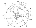
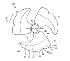
本実施の形態におけるプロペラファン110は、3枚の翼21を有する。プロペラファン110は、駆動モータ(図示せず)に駆動されることによって、中心軸101を中心として矢印102に示す方向に回転する。翼21の回転によって風が生成され、流体送り装置510は送風することが可能となる。
(Propeller fan 110)
Propeller fan 110 in the present embodiment has three blades 21. Propeller fan 110 is driven by a drive motor (not shown) to rotate about center axis 101 in the direction indicated by arrow 102. Wind is generated by the rotation of the blades 21, and the fluid feeder 510 can blow.

プロペラファン110は、3枚以外の複数枚の翼21を備えていてもよいし、1枚のみの翼21を備えていてもよい。プロペラファン110が1枚のみの翼21を備える場合、中心軸101に対して翼21の反対側に、バランサーとしての錘が設けられるとよい。プロペラファン110は、サーキュレータとしての流体送り装置510に限られず、扇風機、エアーコンディショナ、空気清浄機、加湿機、除湿機、ファンヒータ、冷却装置、または換気装置などの各種の流体送り装置に用いられることもできる。   Propeller fan 110 may include a plurality of blades 21 other than three, or may include only one blade 21. When the propeller fan 110 includes only one blade 21, a weight as a balancer may be provided on the opposite side of the blade 21 with respect to the central shaft 101. The propeller fan 110 is not limited to the fluid feed device 510 as a circulator, and is used for various fluid feed devices such as a fan, an air conditioner, an air purifier, a humidifier, a dehumidifier, a fan heater, a cooling device, or a ventilation device. It can also be done.

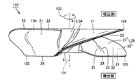
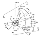
以下、図2〜図10を参照して、プロペラファン110の基本的な構造について説明する。図2は、プロペラファン110を吸込側から見た第1斜視図である。図3は、プロペラファン110を吸込側から見た第2斜視図である。図4は、プロペラファン110を吸込側から見た平面図である。図5は、プロペラファン110を噴出側から見た斜視図である。図6は、プロペラファン110を噴出側から見た平面図である。図7〜図10は、それぞれ、プロペラファン110を示す第1〜第4側面図である。   Hereinafter, the basic structure of the propeller fan 110 will be described with reference to FIGS. FIG. 2 is a first perspective view of the propeller fan 110 viewed from the suction side. FIG. 3 is a second perspective view of the propeller fan 110 viewed from the suction side. FIG. 4 is a plan view of the propeller fan 110 viewed from the suction side. FIG. 5 is a perspective view of the propeller fan 110 viewed from the ejection side. FIG. 6 is a plan view of the propeller fan 110 viewed from the ejection side. 7 to 10 are first to fourth side views showing the propeller fan 110, respectively.

プロペラファン110は、たとえば、AS(acrylonitrile-styrene)樹脂等の合成樹脂により、樹脂成型品として一体成形されている。プロペラファン110は、回転軸部としてのボスハブ部41と、翼21A〜21C(図2参照)とを備える。以下、翼21A〜21Cを特に区別しない場合は、翼21A〜21Cの各々を翼21という。   Propeller fan 110 is integrally molded as a resin molded product by synthetic resin such as AS (acrylonitrile-styrene) resin, for example. The propeller fan 110 includes a boss hub portion 41 as a rotating shaft portion and blades 21A to 21C (see FIG. 2). Hereinafter, when the wings 21A to 21C are not particularly distinguished, each of the wings 21A to 21C is referred to as a wing 21.

プロペラファン110は、たとえば、一枚物の板金を捻り加工することによって作製されてもよいし、曲面を有して形成される一体の薄肉状物から作製されてもよい。これらの場合、そのプロペラファンは、別に成形したボスハブ部41に翼21A、翼21Bおよび翼21Cを接合する構造としてもよい。   Propeller fan 110 may be manufactured, for example, by twisting a single sheet metal, or may be manufactured from an integral thin-walled object formed with a curved surface. In these cases, the propeller fan may have a structure in which the blade 21A, the blade 21B, and the blade 21C are joined to a separately formed boss hub 41.

ボスハブ部41は、プロペラファン110を、駆動源である駆動モータ(図示せず)の出力軸に接続する部分である。ボスハブ部41は、駆動モータからの回転動力を受けることにより、仮想の中心軸101を中心として所定の回転方向(矢印102方向)で回転する。本実施の形態のボスハブ部41は、中心軸101に沿って軸方向に延びる有底の円筒形状を有する。   The boss hub portion 41 is a portion that connects the propeller fan 110 to an output shaft of a drive motor (not shown) that is a drive source. The boss hub portion 41 rotates in a predetermined rotation direction (the direction of the arrow 102) around the virtual center axis 101 by receiving rotational power from the drive motor. The boss hub portion 41 of the present embodiment has a bottomed cylindrical shape extending in the axial direction along the central axis 101.

翼21A〜21C(図2参照)は、ボスハブ部41の外表面41Sから中心軸101の半径方向外側に延出するように形成されている。翼21A〜21Cは、プロペラファン110の回転軸(中心軸101)の周方向において、等間隔に並んで配置されている。翼21Bは、翼21Aに対してプロペラファン110の回転方向の側に隣り合って配置され、翼21Cは、翼21Bに対してプロペラファン110の回転方向の側に隣り合って配置されている。   The wings 21 </ b> A to 21 </ b> C (see FIG. 2) are formed so as to extend outward from the outer surface 41 </ b> S of the boss hub portion 41 in the radial direction of the central shaft 101. The blades 21 </ b> A to 21 </ b> C are arranged at equal intervals in the circumferential direction of the rotation shaft (center shaft 101) of the propeller fan 110. The blade 21B is disposed adjacent to the blade 21A in the rotation direction of the propeller fan 110, and the blade 21C is disposed adjacent to the blade 21B in the rotation direction of the propeller fan 110.

翼21A〜21Cが中心軸101を中心として矢印102に示す方向に回転する際、翼21A〜21Cはボスハブ部41と一体的に回転する。翼21A〜21Cは、中心軸101を中心に回転することにより、図中の吸込側から噴出側に送風を行なう。本実施の形態では、翼21A〜21Cは、同一形状に形成されている。いずれかの翼21を中心軸101を中心に回転させた場合に、その翼21の形状と別の翼21の形状とは一致する。   When the blades 21A to 21C rotate about the central axis 101 in the direction indicated by the arrow 102, the blades 21A to 21C rotate integrally with the boss hub portion 41. The blades 21 </ b> A to 21 </ b> C rotate from the suction side to the ejection side in the figure by rotating around the central axis 101. In the present embodiment, the wings 21A to 21C are formed in the same shape. When one of the blades 21 is rotated around the central axis 101, the shape of the blade 21 and the shape of another blade 21 are the same.

(翼21)
翼21は、翼根部34および翼根部34から板状に延びる翼面28を含む。翼根部34は、翼21とボスハブ部41の外表面41Sとの間(境目)に配置される。翼面28は、正圧面26と、正圧面26の裏側に配置される負圧面27とから構成されている。正圧面26は、中心軸101の軸方向において翼面28の噴出側に位置する。負圧面27は、中心軸101の軸方向において翼面28の吸込側に位置する。正圧面26および負圧面27の各々の表面は、全体として滑らかに形成されている。
(Wings 21)
The blade 21 includes a blade root portion 34 and a blade surface 28 extending from the blade root portion 34 in a plate shape. The blade root portion 34 is disposed between the blade 21 and the outer surface 41S of the boss hub portion 41 (boundary). The blade surface 28 includes a positive pressure surface 26 and a negative pressure surface 27 disposed on the back side of the positive pressure surface 26. The positive pressure surface 26 is located on the ejection side of the blade surface 28 in the axial direction of the central shaft 101. The negative pressure surface 27 is located on the suction side of the blade surface 28 in the axial direction of the central shaft 101. The surfaces of the positive pressure surface 26 and the negative pressure surface 27 are formed smoothly as a whole.

翼面28は、プロペラファン110の回転に伴って送風を行ない、吸込側から噴出側に空気を送り出す。プロペラファン110の回転時、翼面28上で空気流れが発生することに伴って、正圧面26で相対的に大きく、負圧面27で相対的に小さくなる圧力分布が生じる。   The blade surface 28 blows air as the propeller fan 110 rotates, and sends air from the suction side to the ejection side. When the propeller fan 110 rotates, a pressure distribution that is relatively large on the positive pressure surface 26 and relatively small on the negative pressure surface 27 is generated as an air flow is generated on the blade surface 28.

翼面28の周縁には、翼根部34のうちの回転方向の側の部分から翼根部34のうちの回転方向の反対側の部分に向かって、前縁部22、翼先端部104(図4、図6、および図7〜図10参照)、外縁部23、翼後端部105(図4、図6、および図7〜図10参照)、および、後縁部24がこの順で環状に形成される。   At the periphery of the blade surface 28, the leading edge portion 22 and the blade tip portion 104 (see FIG. 4) from the portion of the blade root portion 34 on the rotation direction side toward the portion of the blade root portion 34 opposite to the rotation direction. , FIG. 6 and FIGS. 7 to 10), the outer edge portion 23, the wing trailing end portion 105 (see FIGS. 4, 6, and 7 to 10), and the trailing edge portion 24 are annular in this order. It is formed.

翼21を平面的に見た場合に、翼21は、前縁部22と外縁部23とが交わる翼先端部104を先端にして、鎌状に尖った形状を有する。前縁部22および後縁部24の径方向内側の部分においては、回転方向に沿ったそれらの幅が徐々に小さくなうように構成されており、前縁部22および後縁部24の径方向外側の部分においては、回転方向に沿ったそれらの幅が徐々に大きくなるように構成されている。   When the wing 21 is viewed in a plane, the wing 21 has a sickle-pointed shape with the wing tip portion 104 where the front edge portion 22 and the outer edge portion 23 cross each other as a tip. The radially inner portions of the front edge portion 22 and the rear edge portion 24 are configured such that their widths along the rotation direction are gradually reduced, and the diameters of the front edge portion 22 and the rear edge portion 24 are reduced. In the outer portion in the direction, the width along the rotation direction is gradually increased.

具体的には、前縁部22は、翼21の回転方向(矢印102方向)の上流側に配置される。プロペラファン110を中心軸101の軸方向から見た場合(換言すると、プロペラファン110を平面的に見た場合)に、前縁部22は、翼根部34のうちの回転方向の側の部分から、中心軸101を中心とする半径方向内側から同方向外側に向けて延びている。前縁部22は、中心軸101を中心とする半径方向内側から同方向外側に湾曲しながら、プロペラファン110の回転方向に向かって延びている。   Specifically, the leading edge portion 22 is disposed on the upstream side in the rotation direction of the blade 21 (the direction of the arrow 102). When the propeller fan 110 is viewed from the axial direction of the central shaft 101 (in other words, when the propeller fan 110 is viewed in a plan view), the leading edge portion 22 is from the portion of the blade root portion 34 in the rotational direction. , Extending from the inner side in the radial direction around the central axis 101 toward the outer side in the same direction. The front edge portion 22 extends in the rotational direction of the propeller fan 110 while curving from the radially inner side around the central axis 101 to the outer side in the same direction.

翼先端部104は、中心軸101から見て前縁部22の半径方向外側に配置される。翼先端部104は、前縁部22と次述する外縁部23とが接続される部分である。本実施の形態における翼先端部104は、翼21の中で最も回転方向の側に位置している。   The blade tip portion 104 is disposed on the radially outer side of the leading edge portion 22 when viewed from the central axis 101. The blade tip 104 is a portion where the front edge 22 and the outer edge 23 described below are connected. The blade tip 104 in the present embodiment is located on the most rotational side of the blade 21.

後縁部24は、翼21の回転方向(矢印102方向)の下流側に配置される。プロペラファン110を中心軸101の軸方向から見た場合(換言すると、プロペラファン110を平面的に見た場合)に、後縁部24は、翼根部34のうちの回転方向の反対側の部分から、中心軸101を中心とする半径方向内側から同方向外側に向けて延びている。後縁部24は、中心軸101を中心とする周方向において、前縁部22と対向して配置されている。後縁部24は、中心軸101を中心とする半径方向内側から同方向外側に緩やかに湾曲しながら、プロペラファン110の回転方向に向かって延びている。   The trailing edge 24 is disposed on the downstream side in the rotation direction of the blade 21 (the direction of the arrow 102). When the propeller fan 110 is viewed from the axial direction of the central shaft 101 (in other words, when the propeller fan 110 is viewed in plan), the trailing edge portion 24 is a portion of the blade root portion 34 opposite to the rotational direction. From the inner side in the radial direction with the central axis 101 as the center, the outer side extends in the same direction. The rear edge portion 24 is disposed to face the front edge portion 22 in the circumferential direction around the central axis 101. The rear edge 24 extends in the rotational direction of the propeller fan 110 while gently curving from the radially inner side centered on the central axis 101 to the outer side in the same direction.

翼後端部105は、中心軸101から見て後縁部24の半径方向外側に配置される。翼後端部105は、後縁部24と次述する外縁部23とが接続される部分である。本実施の形態のプロペラファン110における翼先端部104は、翼後端部105よりも中心軸101を中心とする内周側に配置されている。   The blade trailing end portion 105 is disposed on the radially outer side of the trailing edge portion 24 when viewed from the central axis 101. The blade trailing end portion 105 is a portion where the trailing edge portion 24 and an outer edge portion 23 described below are connected. The blade tip 104 of the propeller fan 110 of the present embodiment is disposed on the inner peripheral side with the center axis 101 as the center from the blade trailing edge 105.

外縁部23は、中心軸101の周方向に沿って延び、翼先端部104と翼後端部105との間を接続するように設けられる。外縁部23は、外縁部23の周方向に延びる線上においてプロペラファン110の最も回転方向の側に位置する翼先端部104で前縁部22と交わり、外縁部23の周方向に延びる線上においてプロペラファン110の最も回転方向の反対側に位置する翼後端部105で後縁部24と交わっている。外縁部23は、全体として、翼先端部104と翼後端部105との間で円弧状に延びている。   The outer edge portion 23 extends along the circumferential direction of the central shaft 101 and is provided so as to connect between the blade tip portion 104 and the blade trailing end portion 105. The outer edge portion 23 intersects the front edge portion 22 at the blade tip portion 104 located on the most rotational direction side of the propeller fan 110 on a line extending in the circumferential direction of the outer edge portion 23, and on the line extending in the circumferential direction of the outer edge portion 23. The blade 110 intersects with the trailing edge 24 at the blade trailing end 105 located on the most opposite side of the rotation direction of the fan 110. The outer edge portion 23 extends in an arc shape between the blade tip portion 104 and the blade trailing end portion 105 as a whole.

前縁部22、翼先端部104、外縁部23、翼後端部105、および、後縁部24は、翼根部34とともに翼21の周縁を形成する周縁部を構成している。この周縁部(前縁部22、翼先端部104、外縁部23、翼後端部105、および、後縁部24)は、いずれも概ね弧状の形状を有するように形成されることで、角部を有さない滑らかな形状とされている。翼面28は、翼根部34とこの周縁部(前縁部22、翼先端部104、外縁部23、翼後端部105、および、後縁部24)とに囲まれた領域の内側の全域に亘って形成されている。   The leading edge portion 22, the blade tip portion 104, the outer edge portion 23, the blade trailing end portion 105, and the trailing edge portion 24 constitute a peripheral portion that forms the peripheral edge of the blade 21 together with the blade root portion 34. The peripheral edge portions (the front edge portion 22, the blade tip portion 104, the outer edge portion 23, the blade rear end portion 105, and the rear edge portion 24) are all formed to have a generally arcuate shape. It has a smooth shape with no part. The blade surface 28 is the entire area inside the region surrounded by the blade root 34 and the peripheral edge (the front edge 22, the blade tip 104, the outer edge 23, the blade rear end 105, and the rear edge 24). It is formed over.

図2、図3、図5および図7〜図10を参照して、翼面28は、前縁部22から後縁部24に向かう周方向において、吸込側から噴出側に向かって全体として滑らかに湾曲するように形成されている。本実施の形態のプロペラファン110における翼21は、前縁部22と後縁部24とを結ぶ周方向の断面形状の厚みが、前縁部22および後縁部24から翼中心付近に向かうほど厚くなり、翼中心よりも前縁部22側に寄った位置に最大厚みを有する翼型形状を有している。   2, 3, 5, and 7 to 10, the blade surface 28 is generally smooth from the suction side to the ejection side in the circumferential direction from the front edge portion 22 to the rear edge portion 24. It is formed to be curved. In the blade 21 in the propeller fan 110 of the present embodiment, the thickness of the cross-sectional shape in the circumferential direction connecting the leading edge portion 22 and the trailing edge portion 24 increases from the leading edge portion 22 and the trailing edge portion 24 toward the blade center. It is thicker and has an airfoil shape having a maximum thickness at a position closer to the leading edge 22 side than the blade center.

図4および図6を参照して、複数の翼21の周囲には、仮想的な外接円109が形成される。外接円109は、中心軸101を中心として半径Rを有し、その内側に複数の翼21が内接している。換言すると、翼21は、中心軸101を中心として最大半径Rを有し、外接円109は、翼21の外縁部23に接している。   4 and 6, a virtual circumscribed circle 109 is formed around the plurality of wings 21. The circumscribed circle 109 has a radius R around the central axis 101, and a plurality of blades 21 are inscribed inside the circumscribed circle 109. In other words, the wing 21 has the maximum radius R around the central axis 101, and the circumscribed circle 109 is in contact with the outer edge 23 of the wing 21.

本実施の形態における外縁部23は、外縁部23が外接円109に重なる位置と外縁部23が外接円109から離れる位置との境界に、最大径端部111(図4参照)を有する。外縁部23は、最大径端部111から翼先端部104に向けて、中心軸101を中心とする半径方向内側に湾曲しながら延びている。   The outer edge portion 23 in the present embodiment has a maximum diameter end portion 111 (see FIG. 4) at a boundary between a position where the outer edge portion 23 overlaps the circumscribed circle 109 and a position where the outer edge portion 23 is separated from the circumscribed circle 109. The outer edge portion 23 extends from the maximum diameter end portion 111 toward the blade tip portion 104 while curving inward in the radial direction around the central axis 101.

(内側領域31・外側領域32・連結部33)
図11は、プロペラファン110を部分的に拡大し、吸込側から見た斜視図である。図12は、プロペラファン110を部分的に拡大し、吸込側から見た第1平面図である。図13は、プロペラファン110を部分的に拡大し、吸込側から見た第2平面図である。図14は、図13中のXIV−XIV線に沿った矢視図である。図15は、図13中のXV−XV線に沿った矢視断面図である。
(Inner region 31, outer region 32, connecting portion 33)
FIG. 11 is a perspective view of the propeller fan 110 partially enlarged and viewed from the suction side. FIG. 12 is a first plan view of the propeller fan 110 partially enlarged and viewed from the suction side. FIG. 13 is a second plan view of the propeller fan 110 partially enlarged and viewed from the suction side. FIG. 14 is an arrow view along the line XIV-XIV in FIG. 13. 15 is a cross-sectional view taken along line XV-XV in FIG.

図16は、図13中のXVI−XVI線に沿った矢視断面図である。図17は、図13中のXVII−XVII線に沿った矢視断面図である。図18は、図13中のXVIII−XVIII線に沿った矢視断面図である。図19は、図13中のXIX−XIX線に沿った矢視断面図である。図20は、図13中のXX−XX線に沿った矢視断面図である。図21は、図13中のXXI−XXI線に沿った矢視図である。   16 is a cross-sectional view taken along line XVI-XVI in FIG. 17 is a cross-sectional view taken along the line XVII-XVII in FIG. 18 is a cross-sectional view taken along line XVIII-XVIII in FIG. FIG. 19 is a cross-sectional view taken along line XIX-XIX in FIG. 20 is a cross-sectional view taken along the line XX-XX in FIG. FIG. 21 is an arrow view along the line XXI-XXI in FIG. 13.

図11および図12(ならびに図2〜図10)を参照して、プロペラファン110の翼面28は、内側領域31、外側領域32、および、連結部33を有する。内側領域31、外側領域32、および、連結部33は、正圧面26および負圧面27の双方にそれぞれ形成されている。   Referring to FIGS. 11 and 12 (and FIGS. 2 to 10), the blade surface 28 of the propeller fan 110 has an inner region 31, an outer region 32, and a connecting portion 33. The inner region 31, the outer region 32, and the connecting portion 33 are formed on both the positive pressure surface 26 and the negative pressure surface 27, respectively.

内側領域31は、翼根部34をその一部に含み、連結部33および外側領域32に比べて中心軸101の半径方向の内側に位置する。外側領域32は、翼後端部105をその一部に含み、連結部33および内側領域31に比べて中心軸101の半径方向の外側に位置する。内側領域31における正圧面26の表面形状と、外側領域32における正圧面26の表面形状とは、相互に異なるように形成されている。内側領域31における負圧面27の表面形状と、外側領域32における負圧面27の表面形状とも、相互に異なるように形成されている。   The inner region 31 includes a blade root portion 34 in a part thereof, and is located on the inner side in the radial direction of the central axis 101 compared to the connecting portion 33 and the outer region 32. The outer region 32 includes the blade trailing end portion 105 as a part thereof, and is located on the outer side in the radial direction of the central shaft 101 as compared with the connecting portion 33 and the inner region 31. The surface shape of the pressure surface 26 in the inner region 31 and the surface shape of the pressure surface 26 in the outer region 32 are different from each other. The surface shape of the suction surface 27 in the inner region 31 and the surface shape of the suction surface 27 in the outer region 32 are formed to be different from each other.

連結部33は、翼面28の正圧面26側が凸となり且つ翼面28の負圧面27側が凹となるように、内側領域31と外側領域32とを連結している。連結部33は、概ね回転方向に沿うように設けられており、連結部33のうちの回転方向の最上流側に位置する前端部33Aから、連結部33のうちの回転方向の最下流側に位置する後端部33Bまで延在している。   The connecting portion 33 connects the inner region 31 and the outer region 32 so that the pressure surface 26 side of the blade surface 28 is convex and the negative pressure surface 27 side of the blade surface 28 is concave. The connecting portion 33 is provided substantially along the rotational direction, and from the front end portion 33A located on the most upstream side in the rotating direction of the connecting portion 33 to the most downstream side in the rotating direction of the connecting portion 33. It extends to the rear end portion 33B.

連結部33は、内側領域31から外側領域32に向かうにしたがって翼面28がやや急峻な曲率変化を持って湾曲するようにして形成されており、相互に異なる表面形状を有する内側領域31および外側領域32との境目においてこれら同士を湾曲しながら連結している。   The connecting portion 33 is formed such that the blade surface 28 is curved with a slightly steep curvature change from the inner region 31 toward the outer region 32, and the inner region 31 and the outer region having different surface shapes from each other. These are connected while being curved at the boundary with the region 32.

連結部33は、その付近において翼面28の半径方向断面視における曲率が極大となるように設けられており、正圧面26上においては湾曲状に突出した突条部として前端部33Aから後端部33Bに向かって筋状に延びるように現れており、負圧面27上においては湾曲状の窪んだ溝部として前端部33Aから後端部33Bに向かって筋状に延びるように現れている。   The connecting portion 33 is provided so that the curvature in the radial cross-sectional view of the blade surface 28 is maximized in the vicinity of the connecting portion 33, and is projected from the front end portion 33 </ b> A to the rear end as a projecting ridge portion protruding on the pressure surface 26. It appears to extend in a streak shape toward the portion 33B, and on the negative pressure surface 27, it appears as a curved concave groove to extend in a streak shape from the front end portion 33A toward the rear end portion 33B.

連結部33の前端部33Aは、翼先端部104寄りに位置し、後縁部24からは離れて設けられている。本実施の形態における連結部33の前端部33Aは、翼先端部104から回転方向とは反対側に向かって翼面28の内側にわずかに変位した位置に設けられている(図4、図6、図11、および図12参照)。   The front end portion 33 </ b> A of the coupling portion 33 is located closer to the blade tip portion 104 and is provided away from the rear edge portion 24. The front end portion 33A of the connecting portion 33 in the present embodiment is provided at a position slightly displaced inward of the blade surface 28 from the blade tip portion 104 toward the side opposite to the rotation direction (FIGS. 4 and 6). FIG. 11 and FIG. 12).

連結部33の前端部33Aは、後縁部24から離れていれば、前縁部22寄りに位置するように設けられていてもよいし、外縁部23寄りに位置するように設けられていてもよい。連結部33の前端部33Aは、前縁部22、翼先端部104、または外縁部23のいずれかと重なるように、前縁部22上に設けられていてもよいし、翼先端部104上に設けられていてもよいし、外縁部23上に設けられていてもよい。   The front end portion 33 </ b> A of the connecting portion 33 may be provided so as to be located closer to the front edge portion 22 as long as it is separated from the rear edge portion 24, or provided so as to be located closer to the outer edge portion 23. Also good. The front end portion 33 </ b> A of the connecting portion 33 may be provided on the front edge portion 22 so as to overlap any of the front edge portion 22, the blade tip portion 104, or the outer edge portion 23, or on the blade tip portion 104. It may be provided or may be provided on the outer edge portion 23.

連結部33の後端部33Bは、後縁部24寄りに位置し、前縁部22、翼先端部104および外縁部23のいずれに対しても離れて設けられている。本実施の形態における連結部33の後端部33Bは、中心軸101の半径方向における後縁部24の略中央位置から回転方向に向かって翼面28の内側にわずかに変位した位置に設けられている(図4、図6、図11、および図12参照)。連結部33の後端部33Bは、後縁部24と重なるように、後縁部24上に設けられていてもよい。連結部33は、翼先端部104から翼後端部105までの途中に位置する外縁部23の部分から、後縁部24まで設けられていてもよい。   The rear end portion 33 </ b> B of the connecting portion 33 is located near the rear edge portion 24, and is provided away from any of the front edge portion 22, the blade tip portion 104, and the outer edge portion 23. The rear end portion 33B of the connecting portion 33 in the present embodiment is provided at a position slightly displaced inward of the blade surface 28 from the approximate center position of the rear edge portion 24 in the radial direction of the central shaft 101 in the rotational direction. (See FIG. 4, FIG. 6, FIG. 11, and FIG. 12). The rear end portion 33 </ b> B of the connecting portion 33 may be provided on the rear edge portion 24 so as to overlap the rear edge portion 24. The connecting portion 33 may be provided from a portion of the outer edge portion 23 located in the middle from the blade leading end portion 104 to the blade trailing end portion 105 to the trailing edge portion 24.

図12に示すように、翼21が中心軸101を中心として矢印102に示す方向に回転した場合、翼面28上には、翼先端部104の付近を中心として、前縁部22、翼先端部104、および外縁部23のそれぞれから後縁部24に向かって流れる翼先端渦340が発生する。この翼先端渦340は、正圧面26上および負圧面27上のそれぞれに発生する。好ましくは、連結部33は、この翼先端渦340の流れに沿うように設けられる。   As shown in FIG. 12, when the blade 21 rotates about the central axis 101 in the direction indicated by the arrow 102, the leading edge 22 and the blade tip are centered on the blade surface 28 around the blade tip 104. A blade tip vortex 340 that flows from each of the portion 104 and the outer edge portion 23 toward the rear edge portion 24 is generated. The blade tip vortex 340 is generated on the pressure surface 26 and the suction surface 27, respectively. Preferably, the connecting portion 33 is provided along the flow of the blade tip vortex 340.

(連結部33の湾曲度合い)
図13〜図15に示すように、本実施の形態の連結部33は、連結部33の前端部33Aが前縁部22、翼先端部104、および外縁部23のいずれにも到達しない(重ならない)ように設けられている。連結部33の存在に起因した湾曲は、前縁部22、翼先端部104、および外縁部23のいずれにも現れておらず、連結部33の前端部33Aの周囲に位置する翼面28(正圧面26および負圧面27)は、前端部33Aを通り且つ中心軸101の半径方向に沿った断面視において、180°となるように平坦に形成されている。
(Degree of bending of connecting portion 33)
As shown in FIGS. 13 to 15, in the connecting portion 33 of the present embodiment, the front end portion 33 </ b> A of the connecting portion 33 does not reach any of the front edge portion 22, the blade tip portion 104, and the outer edge portion 23 (heavy weight). It is set up so that it must not. The curvature due to the presence of the connecting portion 33 does not appear in any of the leading edge portion 22, the blade tip portion 104, and the outer edge portion 23, and the blade surface 28 ( The positive pressure surface 26 and the negative pressure surface 27) are formed flat so as to be 180 ° in a sectional view along the radial direction of the central axis 101 through the front end portion 33A.

図13および図16に示すように、連結部33は、翼面28(正圧面26および負圧面27)が連結部33における前端部33Aの回転方向とは反対側の近傍で比較的急峻に湾曲するように設けられている。図13、図17および図18に示すように、連結部33は、連結部33の負圧面27側に仮想的に形成される内角θが、前端部33Aから回転方向における連結部33の中心付近に向かうにつれて徐々に小さくなるように設けられている。好ましくは、この内角θは、回転方向における連結部33の中心付近で最も小さくなるように形成されているとよい。   As shown in FIGS. 13 and 16, the connecting portion 33 is curved relatively steeply in the vicinity of the blade surface 28 (the positive pressure surface 26 and the negative pressure surface 27) on the side opposite to the rotation direction of the front end portion 33 </ b> A in the connecting portion 33. It is provided to do. As shown in FIGS. 13, 17, and 18, the connecting portion 33 has an inner angle θ virtually formed on the suction surface 27 side of the connecting portion 33, near the center of the connecting portion 33 in the rotational direction from the front end portion 33 </ b> A. It is provided so that it gradually becomes smaller as it goes to. Preferably, the inner angle θ is formed to be the smallest in the vicinity of the center of the connecting portion 33 in the rotation direction.

図13および図19に示すように、連結部33は、連結部33の負圧面27側に仮想的に形成される内角θが、回転方向における連結部33の中心付近から後端部33Bに向かうにつれて徐々に大きくなるように設けられている。図13、図20、および図21に示すように、本実施の形態の連結部33は、連結部33の後端部33Bが後縁部24に到達しない(重ならない)ように設けられている。連結部33の存在に起因した湾曲は、後縁部24には現れておらず、連結部33の後端部33Bの周囲に位置する翼面28(正圧面26および負圧面27)は、後端部33Bを通り且つ中心軸101の半径方向に沿った断面視において、180°となるように平坦に形成されている。   As shown in FIGS. 13 and 19, the connecting
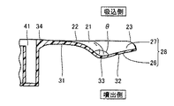
 portion 33 has an inner angle θ virtually formed on the suction surface 27 side of the connecting portion 33 from the vicinity of the center of the connecting portion 33 in the rotation direction toward the rear end portion 33B. It is provided so that it gradually increases with time. As shown in FIGS. 13, 20, and 21, the connecting portion 33 according to the present embodiment is provided so that the rear end portion 33 </ b> B of the connecting portion 33 does not reach the rear edge portion 24 (does not overlap). . The curvature due to the presence of the connecting portion 33 does not appear in the rear edge portion 24, and the blade surface 28 (the positive pressure surface 26 and the negative pressure surface 27) located around the rear end portion 33B of the connecting portion 33 It is formed so as to be 180 ° in a sectional view along the radial direction of the central axis 101 through the end portion 33B.

(食い違い角θA,θB)
図22は、図11中のXXII−XXII線に沿った矢視断面図である。図11および図22に示すように、翼面28のうちの連結部33よりも半径方向内側に位置する内側領域31は、所定の食い違い角θA(図22参照)を有する。内側領域31における前縁部22上の点と内側領域31における後縁部24上の点とを結ぶことにより、仮想直線31L(図22参照)が形成される。食い違い角θAとは、仮想直線31Lと中心軸101とがこれらの間になす角度のことである。
(Difference angle θA, θB)
22 is a cross-sectional view taken along the line XXII-XXII in FIG. As shown in FIGS. 11 and 22, the inner region 31 located on the radially inner side of the connecting portion 33 in the blade surface 28 has a predetermined misalignment angle θA (see FIG. 22). By connecting a point on the front edge 22 in the inner region 31 and a point on the rear edge 24 in the inner region 31, a virtual straight line 31L (see FIG. 22) is formed. The discrepancy angle θA is an angle formed between the virtual straight line 31L and the central axis 101.

図22に示すように、本実施の形態における翼21の内側領域31は、前縁部22および後縁部24を両端として内側領域31の中腹部が仮想直線31Lから噴出側に向かって遠ざかるように湾曲し、翼面28(内側領域31)の正圧面26側が凸となり翼面28(内側領域31)の負圧面27側が凹となるように反った形状を有している。   As shown in FIG. 22, the inner region 31 of the wing 21 in the present embodiment has the front edge portion 22 and the rear edge portion 24 as both ends so that the middle part of the inner region 31 moves away from the virtual straight line 31L toward the ejection side. And has a curved shape such that the pressure surface 26 side of the blade surface 28 (inner region 31) is convex and the negative pressure surface 27 side of the blade surface 28 (inner region 31) is concave.

また、本実施の形態における翼21は、翼面28のうちの連結部33よりも半径方向内側の部分の食い違い角θAが、ボスハブ部41に近づくにしたがって小さくなるように形成されている。   Further, the blade 21 in the present embodiment is formed such that the stagger angle θA of the portion on the radially inner side of the connecting portion 33 in the blade surface 28 becomes smaller as it approaches the boss hub portion 41.

図23は、図11中のXXIII−XXIII線に沿った矢視断面図である。図11および図23に示すように、翼面28のうちの連結部33よりも半径方向外側に位置する外側領域32は、所定の食い違い角θB(図23参照)を有する。外側領域32における前縁部22上の点と外側領域32における後縁部24上の点とを結ぶことにより、仮想直線33L(図23参照)が形成される。食い違い角θBとは、仮想直線33Lと中心軸101とがこれらの間になす角度のことである。   23 is a cross-sectional view taken along line XXIII-XXIII in FIG. As shown in FIGS. 11 and 23, the outer region 32 located on the radially outer side of the connecting portion 33 in the blade surface 28 has a predetermined misalignment angle θB (see FIG. 23). By connecting a point on the front edge 22 in the outer region 32 and a point on the rear edge 24 in the outer region 32, a virtual straight line 33L (see FIG. 23) is formed. The stagger angle θB is an angle formed between the virtual straight line 33L and the central axis 101.

図23に示すように、本実施の形態における翼21の外側領域32は、前縁部22および後縁部24を両端として外側領域32の中腹部が仮想直線33Lから吸込側に向かって遠ざかるように湾曲し、翼面28(外側領域32)の正圧面26側が凹となり翼面28(外側領域32)の負圧面27側が凸となるように反った形状を有している。   As shown in FIG. 23, in the outer region 32 of the wing 21 in the present embodiment, the middle part of the outer region 32 moves away from the virtual straight line 33L toward the suction side with the front edge portion 22 and the rear edge portion 24 as both ends. And has a curved shape so that the pressure surface 26 side of the blade surface 28 (outer region 32) is concave and the suction surface 27 side of the blade surface 28 (outer region 32) is convex.

図22および図23を参照して、本実施の形態における翼21は、食い違い角θBよりも食い違い角θAの方が小さくなるように形成される。翼21は、翼根部34における食い違い角θAも、外縁部23における食い違い角θBに比べて小さくなるように形成される。さらに、翼21は、翼根部34および内側領域31においては正圧面26側が凸となり負圧面27側が凹となるように反った形状を有し、外側領域32および外縁部23においては正圧面26側が凹となり負圧面27側が凸となるように反った形状を有している(逆キャンバー構造)。   Referring to FIGS. 22 and 23, blade 21 in the present embodiment is formed such that stagger angle θA is smaller than stagger angle θB. The wing 21 is formed such that the stagger angle θA at the blade root portion 34 is also smaller than the stagger angle θB at the outer edge portion 23. Further, the blade 21 has a curved shape such that the pressure surface 26 side is convex in the blade root portion 34 and the inner region 31 and the negative pressure surface 27 side is concave, and the pressure surface 26 side is in the outer region 32 and the outer edge portion 23. It has a shape that is concave and warped so that the suction surface 27 side is convex (reverse camber structure).

(作用・効果)
図24〜図26を参照して、本実施の形態における流体送り装置510(図1参照)およびプロペラファン110の作用および効果について説明する。図24は、プロペラファン110の翼21が回転している際の様子を吸込側から見た平面図である。図25は、プロペラファン110の翼21が回転している際の様子を噴出側から見た平面図である。図26は、プロペラファン110を連結部33に沿って仮想的に切断したときの断面図であり、プロペラファン110の翼21が回転している際の様子を示す図である。
(Action / Effect)
With reference to FIGS. 24 to 26, the operation and effect of fluid feeder 510 (see FIG. 1) and propeller fan 110 in the present embodiment will be described. FIG. 24 is a plan view of the propeller fan 110 viewed from the suction side when the blades 21 are rotating. FIG. 25 is a plan view of the propeller fan 110 when the blades 21 are rotating as seen from the ejection side. FIG. 26 is a cross-sectional view when the propeller fan 110 is virtually cut along the connecting portion 33 and is a view showing a state when the blades 21 of the propeller fan 110 are rotating.

図24および図25に示すように、流体送り装置510(図1参照)が使用される際には、プロペラファン110の翼21が中心軸101を中心として矢印102に示す方向に回転する。本実施の形態のプロペラファン110における翼21の翼面28(正圧面26および負圧面27の双方)上には、翼先端渦340、主流310、二次流れ330、馬蹄渦320、および馬蹄渦350が、空気流れとしてそれぞれ発生する。   As shown in FIGS. 24 and 25, when the fluid feeder 510 (see FIG. 1) is used, the blades 21 of the propeller fan 110 rotate about the central axis 101 in the direction indicated by the arrow 102. The blade tip vortex 340, the main flow 310, the secondary flow 330, the horseshoe vortex 320, and the horseshoe vortex on the blade surface 28 (both the pressure surface 26 and the suction surface 27) of the blade 21 in the propeller fan 110 of the present embodiment. 350 are generated as air flows, respectively.

翼先端渦340は、プロペラファン110の回転時、主として翼先端部104が空気と衝突することによって形成される。翼先端渦340は、主として翼先端部104を起点として発生し、翼先端部104、翼先端部104の近傍に位置する前縁部22の翼先端部104寄りの部分、および、翼先端部104の近傍に位置する外縁部23の翼先端部104寄りの部分から、翼面28上を通過して後縁部24に向かってそれぞれ流れる。   Blade tip vortex 340 is formed mainly when blade tip 104 collides with air when propeller fan 110 rotates. The blade tip vortex 340 is generated mainly from the blade tip portion 104, and the blade tip portion 104, the portion of the leading edge portion 22 located near the blade tip portion 104, and the blade tip portion 104. Flows from the portion of the outer edge portion 23 located near the blade tip 104 to the rear edge 24 through the blade surface 28.

主流310は、プロペラファン110の回転時、翼先端渦340よりも翼面28のさらに上層側に形成される。換言すると、主流310は、翼先端渦340が形成される翼面28の表層に対して、翼先端渦340を挟んで翼面28の反対側に形成される。主流310は、前縁部22、翼先端部104、および外縁部23から翼面28上に流入し、後縁部24に向かって流れる。   The main flow 310 is formed further on the blade surface 28 than the blade tip vortex 340 when the propeller fan 110 rotates. In other words, the main flow 310 is formed on the opposite side of the blade surface 28 across the blade tip vortex 340 with respect to the surface layer of the blade surface 28 where the blade tip vortex 340 is formed. The main flow 310 flows from the leading edge portion 22, the blade tip portion 104, and the outer edge portion 23 onto the blade surface 28 and flows toward the trailing edge portion 24.

馬蹄渦320は、プロペラファン110の回転に伴って生じる正圧面26と負圧面27との圧力差に起因して、正圧面26から負圧面27に流れ込むように外縁部23に沿って発生する。二次流れ330は、プロペラファンの回転に伴って生じる遠心力に起因して、ボスハブ部41から外縁部23に向かって流れるように発生する。馬蹄渦350は、連結部33が翼面28に設けられている部分を二次流れ330が横切るように流れることにより発生する。   The horseshoe vortex 320 is generated along the outer edge portion 23 so as to flow from the pressure surface 26 to the suction surface 27 due to the pressure difference between the pressure surface 26 and the suction surface 27 that occurs as the propeller fan 110 rotates. The secondary flow 330 is generated so as to flow from the boss hub portion 41 toward the outer edge portion 23 due to the centrifugal force generated with the rotation of the propeller fan. The horseshoe vortex 350 is generated when the secondary flow 330 flows across the portion where the connecting portion 33 is provided on the wing surface 28.

上述のとおり、本実施の形態における連結部33の前端部33Aは、翼先端部104から回転方向とは反対側に向かって翼面28の内側にわずかに変位した位置に設けられ、連結部33の後端部33Bは、中心軸101の半径方向における後縁部24の略中央位置から回転方向に向かって翼面28の内側にわずかに変位した位置に設けられている(図4、図6、図11、および図12参照)。この構成によって、連結部33は、主流310および翼先端渦340の流れる方向に概ね沿うように形成されることになる。   As described above, the front end portion 33A of the connecting portion 33 in the present embodiment is provided at a position slightly displaced from the blade tip portion 104 to the inside of the blade surface 28 toward the side opposite to the rotation direction. The rear end portion 33B is provided at a position slightly displaced inward of the blade surface 28 from the approximate center position of the rear edge portion 24 in the radial direction of the central shaft 101 in the rotational direction (FIGS. 4 and 6). FIG. 11 and FIG. 12). With this configuration, the connecting portion 33 is formed so as to be substantially along the flowing direction of the main flow 310 and the blade tip vortex 340.

図26に示すように、内側領域31および外側領域32を湾曲して連結する連結部33は、翼面28の表層における連結部33の近傍に、馬蹄渦350および翼先端渦340を保持させ、翼面28の表層から馬蹄渦350および翼先端渦340が剥離してしまうことを抑制する。連結部33は、連結部33の近傍で発生し連結部33によって保持されながら流れる馬蹄渦350が、発達したり変動したりすることも抑制する。   As shown in FIG. 26, the connecting portion 33 that connects the inner region 31 and the outer region 32 in a curved manner holds the horseshoe vortex 350 and the wing tip vortex 340 in the vicinity of the connecting portion 33 on the surface layer of the wing surface 28. The horseshoe vortex 350 and the wing tip vortex 340 are prevented from peeling from the surface layer of the wing surface 28. The connecting portion 33 also prevents the horseshoe vortex 350 that occurs near the connecting portion 33 and flows while being held by the connecting portion 33 from developing or fluctuating.

翼先端部104の近傍で発生し連結部33によって保持されながら流れる翼先端渦340と、連結部33の近傍で発生し連結部33によって保持されながら流れる馬蹄渦350とは、主流310に対して運動エネルギを付与する。運動エネルギを付与された主流310は、翼面28上の下流側で翼面28から剥離しにくくなる。結果として、剥離領域52を縮小もしくは消滅させることができる。プロペラファン110は、剥離が抑制されることによって、回転時に発生する騒音を低減することができ、連結部33を設けない場合と比較して風量を増加させて高効率化することが可能となる。   The wing tip vortex 340 generated near the wing tip 104 and flowing while being held by the connecting portion 33 and the horseshoe vortex 350 generated near the connecting portion 33 and flowing while being held by the connecting portion 33 are Apply kinetic energy. The main flow 310 to which kinetic energy is applied is less likely to separate from the blade surface 28 on the downstream side of the blade surface 28. As a result, the peeling region 52 can be reduced or eliminated. Propeller fan 110 can reduce noise generated during rotation by suppressing separation, and can increase the air volume and increase the efficiency as compared with the case where no connecting portion 33 is provided. .

図27は、一般的なプロペラファンを本実施の形態におけるプロペラファン110の連結部33に対応する部分に沿って仮想的に切断したときの断面図であり、このプロペラファンの翼が回転している際の様子を示す図である。この一般的なプロペラファンは、連結部33を有していない点のほかは、プロペラファン110と略同様に構成される。   FIG. 27 is a cross-sectional view when a general propeller fan is virtually cut along a portion corresponding to the connecting portion 33 of the propeller fan 110 in the present embodiment, and the blades of the propeller fan rotate. It is a figure which shows the mode at the time of being. This general propeller fan is configured in substantially the same manner as the propeller fan 110 except that the connecting portion 33 is not provided.

この一般的なプロペラファンにおいては、翼面28の正圧面26および負圧面27の各々に発生する主流310および翼先端渦340が、前縁部22、翼先端部104、および外縁部23に近い翼面28上の上流側では翼面28に沿った流れとなるものの、後縁部24に近い翼面28上の下流側では翼面28に沿った流れとなりにくい。下流側で翼先端渦340から主流310に対して運動エネルギが付与されないため、主流310が翼面28から剥離する剥離領域52が生じやすい。このプロペラファンは、回転時に発生する騒音を低減することは困難となる。このような傾向は、正圧面26および負圧面27のうち、特に負圧面27上で顕著となる。   In this general propeller fan, the main flow 310 and the blade tip vortex 340 generated on each of the pressure surface 26 and the suction surface 27 of the blade surface 28 are close to the leading edge portion 22, the blade tip portion 104, and the outer edge portion 23. Although the flow is along the blade surface 28 on the upstream side of the blade surface 28, the flow is less likely to flow along the blade surface 28 on the downstream side of the blade surface 28 near the trailing edge 24. Since no kinetic energy is applied to the main flow 310 from the blade tip vortex 340 on the downstream side, a separation region 52 where the main flow 310 separates from the blade surface 28 is likely to occur. With this propeller fan, it is difficult to reduce noise generated during rotation. Such a tendency becomes conspicuous on the suction surface 27 among the suction surface 26 and the suction surface 27.

本実施の形態のプロペラファン110の回転時、連結部33が設けられている領域の近傍においては、主流310は半径方向外側から同方向内側に向かって流れる。したがって、連結部33を主流310の流れに概ね沿うように形成し、連結部33が設けられている領域についても翼型を採用することで、あらゆる主流310の流れに対して翼型を実現できるため、より効率的な送風を行うことが可能となる。   When the propeller fan 110 of the present embodiment rotates, the main flow 310 flows from the radially outer side toward the inner side in the vicinity of the region where the connecting portion 33 is provided. Therefore, the airfoil can be realized for all the mainstream 310 flows by forming the connecting portion 33 so as to substantially follow the flow of the mainstream 310 and adopting the airfoil for the region where the connecting portion 33 is provided. Therefore, it is possible to perform more efficient air blowing.

内側領域31側から外側領域32側に向かって翼面28が滑らかに湾曲するようにして連結部33が設けられていることによって、翼面28の形状に設計上の自由度を確保することができる。たとえば、馬蹄渦の発生を抑制するために、翼先端部104に向かって前縁部22および外縁部23の幅が細くなる鎌形状を維持しながらボスハブ部41付近での翼面28の高さを高くするといった複雑な翼面28の形状についても対応可能となる。   By providing the connecting portion 33 so that the blade surface 28 is smoothly curved from the inner region 31 side toward the outer region 32 side, it is possible to ensure a degree of design freedom in the shape of the blade surface 28. it can. For example, in order to suppress the generation of horseshoe vortices, the height of the wing surface 28 in the vicinity of the boss hub portion 41 while maintaining a sickle shape in which the widths of the front edge portion 22 and the outer edge portion 23 become narrower toward the wing tip portion 104. It is also possible to cope with a complicated shape of the blade surface 28 such as increasing the height.

図13等を参照して上述したとおり、本実施の形態におけるプロペラファン110は、連結部33の前端部33Aの周囲に位置する翼面28(正圧面26および負圧面27)が、前端部33Aを通り且つ中心軸101の半径方向に沿った断面視において180°となるように平坦に形成され、さらに、連結部33の後端部33Bの周囲に位置する翼面28(正圧面26および負圧面27)は、後端部33Bを通り且つ中心軸101の半径方向に沿った断面視において、180°となるように平坦に形成されている。当該構成によれば、翼面28に流入する風および翼面28から流出する風を乱さないので、主流310に対する抵抗を少なくすることが可能となる。なお、当該構成は、必要に応じて設けられるとよい。   As described above with reference to FIG. 13 and the like, propeller fan 110 according to the present embodiment has blade surface 28 (positive pressure surface 26 and negative pressure surface 27) positioned around front end portion 33A of connecting portion 33 at front end portion 33A. Further, the blade surface 28 (the pressure surface 26 and the negative pressure surface 26 and the negative pressure surface 26) is formed so as to be 180 ° in a sectional view along the radial direction of the central axis 101 and positioned around the rear end portion 33B of the connecting portion 33. The pressure surface 27) is formed so as to be 180 ° in a cross-sectional view along the radial direction of the central axis 101 through the rear end portion 33B. According to this configuration, since the wind flowing into the blade surface 28 and the wind flowing out from the blade surface 28 are not disturbed, the resistance to the mainstream 310 can be reduced. Note that this configuration is preferably provided as necessary.

図22および図23等を参照して上述したとおり、本実施の形態におけるプロペラファン110は、翼21が、食い違い角θBよりも食い違い角θAの方が小さくなるように形成される。翼21は、翼根部34における食い違い角θAも、外縁部23における食い違い角θBに比べて小さくなるように形成される。当該構成によれば、不快感の原因となっている半径方向外側の風速のピークを調整することが可能である。   As described above with reference to FIGS. 22 and 23, propeller fan 110 in the present embodiment is formed such that blade 21 has a stagger angle θA smaller than stagger angle θB. The wing 21 is formed such that the stagger angle θA at the blade root portion 34 is also smaller than the stagger angle θB at the outer edge portion 23. According to the said structure, it is possible to adjust the peak of the wind speed of the radial direction outer side which is causing discomfort.

図22および図23等を参照して上述したとおり、本実施の形態における翼21は、翼根部34および内側領域31においては正圧面26側が凸となり負圧面27側が凹となるように反った形状を有し、外側領域32および外縁部23においては正圧面26側が凹となり負圧面27側が凸となるように反った形状を有している。当該構成は、逆キャンバー構造ということができる。   As described above with reference to FIGS. 22, 23, and the like, the blade 21 in the present embodiment is warped so that the pressure surface 26 side is convex and the suction surface 27 side is concave in the blade root 34 and the inner region 31. The outer region 32 and the outer edge portion 23 have a curved shape so that the pressure surface 26 side is concave and the negative pressure surface 27 side is convex. This configuration can be referred to as a reverse camber structure.

一般的なプロペラファンは、その構造に起因して、半径方向内側の部分の周速は遅く、半径方向外側の部分の周速は速くなる。空気の流入角は、半径方向内側に位置する翼根部側と半径方向外側に位置する外縁部側(翼端側)とで異なることになる。したがって、外縁部側(翼端側)で適切な空気の流入が行われるように外縁部側(翼端側)の流入角(キャンバー角)を設計すると、翼根部側では空気の流入が良好に行われにくくなり、翼根部側では空気流れに剥離が生じてしまう場合がある(逆も然り)。   Due to the structure of a general propeller fan, the peripheral speed in the radially inner portion is low and the peripheral speed in the radially outer portion is high. The air inflow angle is different between the blade root side located on the radially inner side and the outer edge side (blade end side) located on the radially outer side. Therefore, if the inflow angle (camber angle) on the outer edge side (wing tip side) is designed so that appropriate air inflow is performed on the outer edge side (blade tip side), the air inflow is good on the blade root side. It becomes difficult to carry out, and separation may occur in the air flow on the blade root side (and vice versa).

そのために、本実施の形態におけるプロペラファン110のように、半径方向内側に位置する翼根部34側と半径方向外側に位置する外縁部23側(翼端側)とでそれぞれ適切にキャンバー角を変化させ、翼根部34側の空気の流入角が大きな領域においては逆キャンバー構造を与えることにより、半径方向の全域にわたって翼面28に対して空気を適切な流入角で流入させることができ、さらには空気流れの剥離を防止することが可能となる。   Therefore, like the propeller fan 110 in the present embodiment, the camber angle is appropriately changed on the blade root portion 34 side located radially inside and the outer edge portion 23 side (blade tip side) located radially outside. By providing a reverse camber structure in a region where the air inflow angle on the blade root 34 side is large, air can be introduced into the blade surface 28 at an appropriate inflow angle over the entire radial direction. It becomes possible to prevent separation of the air flow.

なお、翼根部34および内側領域31においては正圧面26側が凸となり負圧面27側が凹となるように反った形状を有し、外側領域32および外縁部23においては正圧面26側が凹となり負圧面27側が凸となるように反った形状を有するような翼面28の構成(逆キャンバー構造)は、翼面28に連結部33が設けられるという技術的な思想とは独立して実施することが可能である。   The blade root 34 and the inner region 31 have a curved shape such that the pressure surface 26 side is convex and the suction surface 27 side is concave, and the outer surface 32 and the outer edge portion 23 are concave on the pressure surface 26 side and the suction surface. The configuration (reverse camber structure) of the blade surface 28 that has a curved shape so that the 27 side is convex can be implemented independently of the technical idea that the connecting portion 33 is provided on the blade surface 28. Is possible.

プロペラファンに連結部33が設けられていなくても、翼面28が逆キャンバー構造を有するという構成によれば、半径方向の全域にわたって翼面28に対して空気を適切な流入角で流入させることができ、さらには空気流れの剥離を防止するといった課題が解決されることとなる。   Even if the propeller fan is not provided with the connecting portion 33, according to the configuration in which the blade surface 28 has the reverse camber structure, air can flow into the blade surface 28 at an appropriate inflow angle over the entire radial direction. In addition, the problem of preventing the separation of the air flow is solved.

図22等を参照して上述したとおり、本実施の形態における翼21は、翼面28のうちの連結部33よりも半径方向内側の部分の食い違い角θAが、ボスハブ部41に近づくにしたがって小さくなるように形成されている。当該構成によって、中心軸101を中心とする内周側においては、中心軸101に近づくにつれて送風能力が高くなる。   As described above with reference to FIG. 22 and the like, in the blade 21 according to the present embodiment, the stagger angle θA of the portion on the radially inner side of the connecting portion 33 of the blade surface 28 decreases as the boss hub portion 41 approaches. It is formed to become. With this configuration, on the inner peripheral side with the center axis 101 as the center, the air blowing capability increases as the center axis 101 is approached.

一般的なプロペラファンにおいては、半径方向の吹き出し風速分布に大きな差があり、半径方向外側では風速が大きくなり、翼の先端部付近では最も高速となり極端なピーク点を有する。中心軸101の近傍の翼21が機能していない部分と、翼21が最も機能している部分とでは、風速の差が過大となり、吹き出し風速のムラが生じ、これが不快感の大きな原因となってしまう。   In a general propeller fan, there is a large difference in the radial wind speed distribution in the radial direction, the wind speed increases on the outer side in the radial direction, the highest speed is near the tip of the blade, and there is an extreme peak point. The difference in wind speed between the portion where the blade 21 in the vicinity of the central shaft 101 is not functioning and the portion where the blade 21 is functioning most is excessive, resulting in unevenness of the blown wind speed, which is a major cause of discomfort. End up.

これに対して本実施の形態におけるプロペラファン110によれば、内周側と外周側との間の風量(風速)の差を緩和することができる。プロペラファン110によってより均一な送風が行われ、送風を受けた人が不快に感じることを抑制することが可能となる。プロペラファン110によれば、ファンの占有可能な空間を最大限活用することもでき、強力な送風をすることも可能となる。なお、当該構成は、必要に応じて設けられるとよい。   On the other hand, according to propeller fan 110 in the present embodiment, the difference in the air volume (wind speed) between the inner peripheral side and the outer peripheral side can be reduced. The propeller fan 110 performs more uniform air blowing, and it is possible to suppress a person who receives the air from feeling uncomfortable. According to the propeller fan 110, the space that the fan can occupy can be utilized to the maximum, and strong air can be blown. Note that this configuration is preferably provided as necessary.

プロペラファン110によってより均一な送風を行うという観点からは、翼21は、翼21のうちの連結部33よりも半径方向内側の部分(内側領域31)の翼面積が、翼面28のうちの連結部33よりも半径方向外側の部分(外側領域32)の翼面積と同一若しくはこれよりも大きくなるように形成されているとよい。   From the viewpoint of more uniform air blowing by the propeller fan 110, the blade 21 has a blade area of a portion (inner region 31) radially inward of the connecting portion 33 of the blade 21. It is good to form so that it may become the same or larger than the wing | blade area of the part (outer area | region 32) radially outside the connection part 33. FIG.

当該構成によって、翼21のうちの連結部33よりも半径方向内側の部分(内側領域31)の送風能力を増加させ、翼面28のうちの連結部33よりも半径方向外側の部分(外側領域32)の送風能力を低減することができる。内周側と外周側との間の風量(風速)の差を緩和することができ、プロペラファン110によってより均一な送風が行われ、送風を受けた人が不快に感じることを抑制することが可能となる。当該構成は、必要に応じて設けられるとよい。   With this configuration, the air blowing capacity of the portion (inner region 31) radially inward of the connecting portion 33 in the blade 21 is increased, and the portion (outer region) radially outer than the connecting portion 33 in the blade surface 28 is increased. 32) can reduce the blowing capacity. The difference in the air volume (wind speed) between the inner peripheral side and the outer peripheral side can be alleviated, and more uniform air blowing is performed by the propeller fan 110, and it is possible to prevent the person receiving the air from feeling uncomfortable. It becomes possible. The said structure is good to be provided as needed.

[実施の形態1の変形例]
上述の実施の形態1におけるプロペラファン110の連結部33は、内側領域31から外側領域32に向かうにしたがって翼面28がやや急峻な曲率変化を持って湾曲するようにして形成されており、相互に異なる表面形状を有する内側領域31および外側領域32との境目においてこれら同士を湾曲しながら連結している。
[Modification of Embodiment 1]
The connecting portion 33 of the propeller fan 110 in the first embodiment is formed such that the blade surface 28 is curved with a slightly steep curvature change from the inner region 31 toward the outer region 32. Are connected while being curved at the boundary between the inner region 31 and the outer region 32 having different surface shapes.

図28に示すように、連結部33は、内側領域31から外側領域32に向かうにしたがって翼面28がやや急峻な曲率変化を持って湾曲するようにして形成され、相互に異なる表面形状を有する内側領域31および外側領域32との境目においてこれら同士を屈曲しながら連結していてもよい。当該構成によっても、上述の実施の形態1におけるプロペラファン110と略同様の作用および効果を得ることができる。   As shown in FIG. 28, the connecting portion 33 is formed such that the blade surface 28 is curved with a slightly steep curvature change from the inner region 31 to the outer region 32, and has mutually different surface shapes. They may be connected while being bent at the boundary between the inner region 31 and the outer region 32. Also with this configuration, substantially the same operations and effects as the propeller fan 110 in the first embodiment described above can be obtained.

なお、連結部33において翼面28があまり極端に折れ曲がると、その連結部33の形状は、翼面28で発生する主流ではない二次流れに影響しやすくなる。同じ空間を最大限使用する場合にも、連結部33での空気流れを考慮し、適切な湾曲度合いまたは屈曲度合いを定めるとよい。   Note that if the blade surface 28 bends excessively in the connecting portion 33, the shape of the connecting portion 33 tends to affect a secondary flow that is not the mainstream generated on the blade surface 28. Even when the same space is used as much as possible, an appropriate degree of bending or bending may be determined in consideration of the air flow at the connecting portion 33.

[実施の形態2]
図29および図30を参照して、本実施の形態におけるプロペラファン120について説明する。プロペラファン120は、上述の実施の形態1におけるプロペラファン110の構成に加えて、前縁部22から外縁部23の翼先端部104寄りの部分までの領域R1において、中心軸101の軸方向においてこれらが一定の高さを維持するように形成されている。本実施の形態におけるこの領域R1は、前縁部22上においてはその全域に亘って形成されており、外縁部23上においては、最大径端部111よりも翼先端部104寄りの部分に形成されている。
[Embodiment 2]
With reference to FIGS. 29 and 30, propeller fan 120 in the present embodiment will be described. In addition to the configuration of propeller fan 110 in the first embodiment, propeller fan 120 is arranged in the axial direction of central axis 101 in region R1 from front edge portion 22 to the portion near outer blade portion 104 of outer edge portion 23. These are formed so as to maintain a constant height. This region R1 in the present embodiment is formed over the entire region on the front edge portion 22, and is formed on the outer edge portion 23 in a portion closer to the blade tip portion 104 than the maximum diameter end portion 111. Has been.

軸方向の高さの基準面として、噴出側において中心軸101に直交する仮想平面を規定したとする。この場合、一般的なプロペラファンの前縁部22は、前縁部22の仮想平面からの高さが、中心軸101の外周側で高く、内周側で低く設けられる。この場合、翼21の仮想平面からの高さが、中心軸101を中心とする外周側と比較して、内周側で極端に小さくなり、その内周側における翼21の送風能力が極めて低くなってしまう。   Assume that a virtual plane orthogonal to the central axis 101 is defined on the ejection side as a reference plane for the height in the axial direction. In this case, the front edge portion 22 of a general propeller fan is provided such that the height of the front edge portion 22 from the virtual plane is high on the outer peripheral side of the central shaft 101 and low on the inner peripheral side. In this case, the height of the blade 21 from the virtual plane is extremely small on the inner peripheral side compared to the outer peripheral side with the central axis 101 as the center, and the air blowing capacity of the blade 21 on the inner peripheral side is extremely low. turn into.

これに対して、本実施の形態におけるプロペラファン120においては、前縁部22が、中心軸101を中心とする内周側と外周側との間で一定の高さを有する。このような構成により、中心軸101を中心とする内周側において翼21の仮想平面からの高さが大きく設定されることになり、送風能力を向上させることができる。これにより、同じ直径および同じ高さの翼を有する一般的なプロペラファンと比較した場合に、プロペラファンから送り出される風量を大幅に増大させることができる。   On the other hand, in the propeller fan 120 in the present embodiment, the front edge portion 22 has a constant height between the inner peripheral side and the outer peripheral side with the central axis 101 as the center. With such a configuration, the height from the imaginary plane of the blade 21 is set large on the inner peripheral side with the central axis 101 as the center, and the blowing capacity can be improved. Thereby, when compared with a general propeller fan having blades having the same diameter and the same height, the amount of air sent from the propeller fan can be greatly increased.

中心軸101を中心とする内周側で送風能力を高めることによって、複数の翼21の回転によって仮想的に形成される占有空間の体積に対する送風効率を高めることができる。この場合、同一風量を送風することに際しても、翼21の回転数をより低い値に抑えることができるため、省エネルギや低騒音の観点において有利となる。   By increasing the blowing capacity on the inner peripheral side with the central axis 101 as the center, the blowing efficiency with respect to the volume of the occupied space virtually formed by the rotation of the plurality of blades 21 can be increased. In this case, when the same air volume is blown, the rotational speed of the blade 21 can be suppressed to a lower value, which is advantageous in terms of energy saving and low noise.

また、中心軸101を中心とする内周側で送風能力を高めることによって、内周側と外周側との間の風量(風速)の差を緩和することができる。これにより、プロペラファン120からより均一な送風が可能となり、送風を受けた人が不快に感じることを防止できる。   Moreover, the difference in the air volume (wind speed) between the inner peripheral side and the outer peripheral side can be reduced by increasing the blowing capacity on the inner peripheral side with the central axis 101 as the center. As a result, more uniform air can be blown from the propeller fan 120, and it can be prevented that a person receiving the air feels uncomfortable.

[実施の形態2の変形例]
上述の実施の形態2におけるプロペラファン120では、前縁部22から外縁部23の翼先端部104寄りの部分までの領域R1が、前縁部22上においてはその全域に亘って形成されており、外縁部23上においては、最大径端部111よりも翼先端部104寄りの部分に形成されている。
[Modification of Embodiment 2]
In the propeller fan 120 according to the second embodiment described above, the region R1 from the front edge portion 22 to the portion of the outer edge portion 23 near the blade tip portion 104 is formed over the entire area on the front edge portion 22. On the outer edge portion 23, it is formed in a portion closer to the blade tip portion 104 than the maximum diameter end portion 111.

図31に示すプロペラファン120Aのように、上記の領域R1は、ボスハブ部41と、ボスハブ部41から中心軸101の半径方向外側に離れた位置との間に形成されていてもよい。プロペラファン120Aの前縁部22も、領域R1において中心軸101の軸方向において一定の高さを有している。   As in the case of the propeller fan 120A shown in FIG. 31, the region R1 may be formed between the boss hub portion 41 and a position away from the boss hub portion 41 radially outward of the central shaft 101. The front edge portion 22 of the propeller fan 120A also has a certain height in the axial direction of the central axis 101 in the region R1.

前縁部22が中心軸101の軸方向において一定の高さを有する領域R1は、たとえば、ボスハブ部41と、中心軸101から0.4R〜0.6R(Rは、プロペラファン120の平面視における翼21の最大半径(図4および図6参照))だけ離れた位置との間に形成される。   The region R1 in which the front edge portion 22 has a certain height in the axial direction of the central axis 101 is, for example, 0.4 R to 0.6R (R is a plan view of the propeller fan 120) from the boss hub 41 and the central axis 101. And a position separated by a maximum radius of the wing 21 (see FIGS. 4 and 6).

プロペラファン120Aのように、中心軸101の軸方向において一定の高さを有する領域R1が前縁部22のボスハブ部41よりの一部に形成されている場合であっても、中心軸101を中心とする内周側において翼21の高さが大きく設定されることになり、送風能力を向上させることができ、上述の実施の形態2におけるプロペラファン120と略同様の作用および効果を得ることが可能となる。   Even when the region R1 having a certain height in the axial direction of the central shaft 101 is formed in a part from the boss hub portion 41 of the front edge portion 22 like the propeller fan 120A, the central shaft 101 is The height of the blades 21 is set to be large on the inner peripheral side as the center, so that the air blowing capability can be improved, and substantially the same operation and effect as the propeller fan 120 in the second embodiment described above can be obtained. Is possible.

また、翼21の前縁部22の高さが、ボスハブ部41からある区間までは一定とし、それ以降は低くなっていくように構成してもよい。この構成によると、前縁部22のボスハブ部41側の部分が、前縁部22の翼先端部104側の部分に比べて高くなる。半径方向内側では遅くなりがちな風速が速くなるため、前縁部22のボスハブ部41側の部分と前縁部22の翼先端部104側の部分との間に生じてしまう風速の差を縮めることが可能となる。結果として、翼21の下流側で発生する風のムラが小さくなる。前縁部22のボスハブ部41側の部分での風速が遅く、前縁部22の翼先端部104側の部分で風速が極端に速くなってしまうことを抑えることにより、半径方向で風速の分布が均一になるため、生じる風がより滑らかで快適となる。   Further, the height of the front edge portion 22 of the wing 21 may be constant from the boss hub portion 41 to a certain section, and lower thereafter. According to this configuration, the portion of the leading edge portion 22 on the boss hub portion 41 side is higher than the portion of the leading edge portion 22 on the blade tip portion 104 side. Since the wind speed, which tends to be slow at the inner side in the radial direction, increases, the difference in wind speed generated between the portion on the boss hub portion 41 side of the front edge portion 22 and the portion on the blade tip portion 104 side of the front edge portion 22 is reduced. It becomes possible. As a result, the unevenness of the wind generated on the downstream side of the blade 21 is reduced. By suppressing the wind speed at the boss hub 41 side portion of the leading edge 22 from being slow and suppressing the wind speed from becoming extremely high at the blade tip portion 104 side of the leading edge portion 22, the distribution of the wind speed in the radial direction is achieved. Makes the resulting wind smoother and more comfortable.

[実施の形態3]
図32を参照して、本実施の形態におけるプロペラファン130について説明する。プロペラファン130は、上述の実施の形態2におけるプロペラファン120の構成に加えて、後縁部24が、中心軸101を中心とする外周側の領域R2で、中心軸101の軸方向において一定の高さを有している。
[Embodiment 3]
With reference to FIG. 32, propeller fan 130 in the present embodiment will be described. In the propeller fan 130, in addition to the configuration of the propeller fan 120 in the above-described second embodiment, the rear edge 24 is a region R2 on the outer peripheral side centering on the central axis 101, and is constant in the axial direction of the central axis 101. Has a height.

図32中には、プロペラファン130の噴出側に、中心軸101に直交する仮想平面107が示されている。この仮想平面107を基準にして、後縁部24は、中心軸101を中心とする外周側の領域R2で一定の高さH2を有している。   In FIG. 32, a virtual plane 107 orthogonal to the central axis 101 is shown on the ejection side of the propeller fan 130. With reference to this virtual plane 107, the rear edge 24 has a constant height H2 in an outer peripheral region R2 centered on the central axis 101.

このような構成によれば、中心軸101を中心とする外周側においても、翼21の高さを大きく維持する。これにより、複数の翼21の回転によって仮想的に形成される占有空間の体積に対するプロペラファン130の送風効率をさらに高めることができる。   According to such a configuration, the height of the blade 21 is kept large even on the outer peripheral side centering on the central shaft 101. Thereby, the ventilation efficiency of the propeller fan 130 with respect to the volume of the occupied space virtually formed by the rotation of the plurality of blades 21 can be further increased.

プロペラファン130では、駆動モータから延出する回転シャフトにボスハブ部41を固定するための図示しないスピンナーと、翼21とが相互に干渉することを避けるために、後縁部24の高さが、中心軸101を中心とする内周側で高くなっている。このような構成に限られず、ボスハブ部41を噴出側に延長して、後縁部24の高さをボスハブ部41と外縁部23との間で一定としてもよい。   In the propeller fan 130, the height of the rear edge 24 is set to avoid interference between a spinner (not shown) for fixing the boss hub 41 to a rotating shaft extending from the drive motor and the blade 21. It is higher on the inner peripheral side centering on the central axis 101. The configuration is not limited to this, and the boss hub 41 may be extended to the ejection side, and the height of the rear edge 24 may be constant between the boss hub 41 and the outer edge 23.

[実施の形態4]
図33〜図38を参照して、本実施の形態におけるプロペラファン140について説明する。図33および図34に示すように、プロペラファン140の翼21は、上述の実施の形態3におけるプロペラファン130の翼21の構成に加えて、翼21の外縁部23が、前縁部22側に位置する前方外縁部37と、後縁部24側に位置する後方外縁部39と、前方外縁部37および後方外縁部39を接続する所定形状の接続部38とを含んでいる。本実施の形態においては、翼21の外縁部23に、中心軸101側に向けて窪む形状を有する接続部38が形成されている。接続部38は、外縁部23における翼先端部104と翼後端部105との間の途中の位置に形成されている。外縁部23に接続部38が形成されることにより、翼21の外縁部23には、外縁部23の翼先端部104側に位置する前方外縁部37と、外縁部23の翼後端部105側に位置する後方外縁部39とが設けられることになる。
[Embodiment 4]
With reference to FIGS. 33 to 38, propeller fan 140 in the present embodiment will be described. As shown in FIGS. 33 and 34, the blade 21 of the propeller fan 140 is configured such that, in addition to the configuration of the blade 21 of the propeller fan 130 in the third embodiment described above, the outer edge portion 23 of the blade 21 is on the front edge portion 22 side. A front outer edge portion 37 located at the rear edge portion, a rear outer edge portion 39 located on the rear edge portion 24 side, and a connection portion 38 having a predetermined shape for connecting the front outer edge portion 37 and the rear outer edge portion 39. In the present embodiment, a connection portion 38 having a shape that is recessed toward the central axis 101 side is formed on the outer edge portion 23 of the blade 21. The connecting portion 38 is formed at a midway position between the blade leading end portion 104 and the blade trailing end portion 105 in the outer edge portion 23. By forming the connection portion 38 on the outer edge portion 23, the outer edge portion 23 of the wing 21 has a front outer edge portion 37 positioned on the blade tip portion 104 side of the outer edge portion 23, and a blade trailing end portion 105 of the outer edge portion 23. A rear outer edge 39 located on the side is provided.

ここで、接続部38は、図示するように滑らかに湾曲した形状となるように形成されていることが好ましいが、必ずしもこれが湾曲した形状とされず、屈曲した形状とされていてもよい。本実施の形態においては、接続部38が外縁部23上において比較的浅く窪むように形成されているため、接続部38は、略鈍角形状を有している。接続部38が形成される位置は、外縁部23上の位置であれば特に限定されるものではないが、本実施の形態においては、外縁部23の翼後端部105寄りの位置に接続部38が形成されている。本実施の形態においては、前方外縁部37の回転方向に沿った幅は、後方外縁部39の回転方向に沿った幅よりも大きく形成されている。このような形状の外縁部23とすることにより、以下のような効果が得られることになる。   Here, the connecting portion 38 is preferably formed to have a smoothly curved shape as shown in the drawing, but this is not necessarily a curved shape, and may be a bent shape. In the present embodiment, since the connection portion 38 is formed to be recessed relatively shallowly on the outer edge portion 23, the connection portion 38 has a substantially obtuse angle shape. The position at which the connection portion 38 is formed is not particularly limited as long as it is a position on the outer edge portion 23. However, in the present embodiment, the connection portion is located at a position near the blade rear end portion 105 of the outer edge portion 23. 38 is formed. In the present embodiment, the width along the rotation direction of the front outer edge portion 37 is formed larger than the width along the rotation direction of the rear outer edge portion 39. By using the outer edge portion 23 having such a shape, the following effects can be obtained.

第一に、上記構成の翼21とすることにより、径方向における風速分布をより均一にすることができ、風速のムラを抑制することが可能となって風当たりの良い風とすることができる。   First, by using the blade 21 having the above-described configuration, the wind speed distribution in the radial direction can be made more uniform, and the unevenness of the wind speed can be suppressed, and a wind with good wind perception can be obtained.

すなわち、外縁部23に窪み形状の接続部38が形成されていない翼形状とした場合には、径方向外側に向かうにつれてほぼ比例して風速が大きくなるため、径方向内側寄りの部分において発生する風の風速と、径方向外側寄りの部分において発生する風の風速との間に大きな差が生じ、発生する風に大きな風速のムラが生じてしまうことになる。   That is, in the case where the outer edge portion 23 has a wing shape in which the concave connection portion 38 is not formed, the wind speed increases in proportion to the outer side in the radial direction. A large difference is generated between the wind speed of the wind and the wind speed of the wind generated in the portion closer to the outer side in the radial direction, and large wind speed unevenness occurs in the generated wind.

これに対し、本実施の形態においては、外縁部23上に窪み形状の接続部38が形成されているため、外縁部23上に窪み形状の接続部38が形成されていない場合に比べ、外縁部23近傍(すなわち径方向外側寄りの部分)において翼面積が減少することになる。そのため、径方向外側に向かうにつれてほぼ比例して大きくなる風速が、外縁部23寄りの部分において緩和されることになり、径方向内側寄りの部分において発生する風の風速と、外縁部23寄りの部分において発生する風の風速とが近づくことになり、径方向における風速分布がより均一になる。したがって、風速のムラが抑制可能となり、風当たりの良い風とすることができる。   On the other hand, in the present embodiment, since the recess-shaped connection portion 38 is formed on the outer edge portion 23, the outer edge is compared with the case where the recess-shaped connection portion 38 is not formed on the outer edge portion 23. The blade area decreases in the vicinity of the portion 23 (that is, the portion closer to the outside in the radial direction). Therefore, the wind speed that increases in proportion to the outer side in the radial direction is moderated in the portion near the outer edge 23, and the wind speed generated in the portion closer to the inner side in the radial direction is closer to the outer edge 23. The wind speed of the wind generated in the part approaches, and the wind speed distribution in the radial direction becomes more uniform. Therefore, unevenness in the wind speed can be suppressed, and a wind with good wind perception can be obtained.

第二に、上記構成の翼21とすることにより、径方向外側寄りの部分において発生される風に含まれる圧力変動が小さくなる風当たりの良い風を発生させることができる。   Secondly, by using the blade 21 having the above-described configuration, it is possible to generate a wind with good wind perception, in which the pressure fluctuation included in the wind generated in the radially outer portion is reduced.

すなわち、外縁部23に窪み形状の接続部38が形成されていない翼形状とした場合には、翼と翼との間の比較的大きな空間を空気が通過することとなり、発生する風に大きな圧力変動が生じてしまうことになる。これは、より風速の速い風が発生される外縁部23側の部分において特に顕著となり、翼21の枚数が少なくなればなるほど大きな圧力差を含む風が発生することになる。   That is, in the case where the outer edge portion 23 has a wing shape in which the recessed connection portion 38 is not formed, air passes through a relatively large space between the wings, and a large pressure is applied to the generated wind. Variation will occur. This is particularly noticeable in the portion on the outer edge 23 side where a wind having a higher wind speed is generated. As the number of blades 21 decreases, a wind including a large pressure difference is generated.

これに対し、本実施の形態においては、外縁部23に窪み形状の接続部38が形成された翼形状であるため、1枚の翼21の前方外縁部37と後方外縁部39との間に比較的小さな空間(すなわち窪み形状の接続部38が位置する空間)が形成されることになり、当該空間が、翼21の中に風を発生させない空間として存在することになる。   On the other hand, in the present embodiment, since the wing shape is such that the outer edge portion 23 is formed with a recessed connection portion 38, the space between the front outer edge portion 37 and the rear outer edge portion 39 of one wing 21. A relatively small space (i.e., a space where the depression-shaped connecting portion 38 is located) is formed, and the space exists in the blade 21 as a space that does not generate wind.

その結果、風速の速い風が発生される外縁部23側の部分において、翼面積が減少することで発生される風に生じる圧力差が緩和されることとなる上に、圧力変動がより小刻みに生じることになるため、1枚の翼21に設けられた前方外縁部37と後方外縁部39とがあたかも2枚分の翼で風を送風する場合と近似の役目を果たすことになり、全体として圧力変動が小さな風当たりの良い風を発生させることができる。   As a result, in the portion on the outer edge portion 23 side where the high wind speed is generated, the pressure difference generated in the wind generated by the reduction of the blade area is relieved, and the pressure fluctuation is further reduced. As a result, the front outer edge portion 37 and the rear outer edge portion 39 provided on one wing 21 will play an approximate role as if air is blown by two wings. It is possible to generate a breeze with a small pressure fluctuation.

第三に、上記構成の翼21とすることにより、低速回転時においては、広範囲に拡散する風当たりの良い風とすることができ、高速回転時においては、直進性が高くより遠くへ到達する風とすることができる。この点につき、図35ないし図38を参照して、より詳細に説明する。   Thirdly, by using the wing 21 having the above-described configuration, it is possible to obtain a wind with good wind permeation that diffuses over a wide range at low speed rotation, and at high speed rotation, the wind that travels far and has high straightness. It can be. This point will be described in more detail with reference to FIGS.

図35は、プロペラファン140を低速回転させた場合に得られる風の流れを示す概念図である。図36は、流体送り装置520においてプロペラファン140を低速回転させた場合に得られる風の状態を模式的に示す図である。図37は、プロペラファン140を高速回転させた場合に得られる風の流れを示す概念図である。図38は、流体送り装置520においてプロペラファン140を高速回転させた場合に得られる風の状態を模式的に示す図である。図35および図37においては、翼先端渦の代表的な軌道として、外縁部23の翼先端部104付近で発生する翼先端渦の軌道を破細線にて模式的に示し、馬蹄渦の代表的な軌道を細線にて模式的に示し、さらに翼21の外縁部23寄りの位置にて発生される風の軌道を太線にて模式的に示している。   FIG. 35 is a conceptual diagram showing a wind flow obtained when propeller fan 140 is rotated at a low speed. FIG. 36 is a diagram schematically showing the state of wind obtained when propeller fan 140 is rotated at low speed in fluid feeder 520. FIG. 37 is a conceptual diagram showing the flow of wind obtained when propeller fan 140 is rotated at a high speed. FIG. 38 is a diagram schematically showing the state of wind obtained when propeller fan 140 is rotated at high speed in fluid feeder 520. In FIGS. 35 and 37, as a typical trajectory of the wing tip vortex, the trajectory of the wing tip vortex generated in the vicinity of the wing tip portion 104 of the outer edge portion 23 is schematically shown by a broken line. The trajectory of the wind generated at a position near the outer edge 23 of the blade 21 is schematically indicated by a thick line.

上述したように、本実施の形態においては、翼21の外縁部23上の位置に窪み形状の接続部38が形成されている。外縁部23上の位置は、翼先端部104の下流側であってかつ翼面上を流れる翼先端渦の流線に沿った位置に該当することになる。   As described above, in the present embodiment, the recessed connection portion 38 is formed at a position on the outer edge portion 23 of the wing 21. The position on the outer edge portion 23 corresponds to a position along the streamline of the blade tip vortex that is downstream of the blade tip portion 104 and flows on the blade surface.

図35に示すように、翼21が低速で回転した場合には、翼21が回転することで生じる翼先端渦および馬蹄渦の運動エネルギーが小さく、そのため翼先端渦および馬蹄渦が窪み形状の接続部38によって捉えられることなく当該部分においてその剥離が促されることになる。これにより、翼先端渦および馬蹄渦は、いずれも窪み形状の接続部38が形成された部分において遠心力によって半径方向外側に飛ばされることになる。したがって、図36に示すように、翼21で発生された風が流体送り装置520の前方において拡散することになり、風当たりの良い風800が広範囲に送風できることになる。そのため、夜間等の就寝時に風を殆ど感じることなく扇風機を運転させたい場合に、これを満足する微風運転の実現も可能になる。   As shown in FIG. 35, when the wing 21 rotates at a low speed, the kinetic energy of the wing tip vortex and the horseshoe vortex generated by the rotation of the wing 21 is small. The separation is promoted at the portion without being caught by the portion 38. As a result, the wing tip vortex and the horseshoe vortex are both blown outward in the radial direction by centrifugal force at the portion where the recess-shaped connecting portion 38 is formed. Therefore, as shown in FIG. 36, the wind generated by the blades 21 diffuses in front of the fluid feeder 520, and the wind 800 having good wind permeation can be blown over a wide range. For this reason, when it is desired to operate the fan without feeling the wind at bedtime at night or the like, it is possible to realize a breeze operation that satisfies this condition.

一方、図37に示すように、翼21が高速で回転した場合には、翼21が回転することで生じる翼先端渦および馬蹄渦の運動エネルギーが大きく、そのため翼先端渦および馬蹄渦が窪み形状の接続部38によって捉えられて保持されることになり、翼先端渦および馬蹄渦の変動や発達が抑制されることになる。また、その際、翼先端渦および馬蹄渦が窪み形状の接続部38に沿って内側に移動することになるため、その後、外縁部23の翼後端部105において剥離した翼先端渦および馬蹄渦が高速回転による大風量および高静圧によって軸方向に飛ばされることになる。したがって、図38に示すように、翼21で発生された風が流体送り装置520の前方において収束することになり、直進性が高くより遠くへ到達する風900が送風できることになる。そのため、効率よく送風を行なうことが可能になるとともに、風の直進性が高まることによって騒音の発生をも抑制することが可能になる。   On the other hand, as shown in FIG. 37, when the wing 21 rotates at a high speed, the kinetic energy of the wing tip vortex and the horseshoe vortex generated by the rotation of the wing 21 is large. Therefore, the fluctuation and development of the wing tip vortex and the horseshoe vortex are suppressed. At this time, since the wing tip vortex and the horseshoe vortex move inward along the hollow connecting portion 38, the wing tip vortex and the horseshoe vortex peeled off at the wing rear end portion 105 of the outer edge 23 thereafter. Is blown in the axial direction by a large air volume and high static pressure by high-speed rotation. Therefore, as shown in FIG. 38, the wind generated by the blades 21 converges in front of the fluid feeding device 520, and the wind 900 that travels farther and has a higher degree of straightness can be blown. Therefore, it is possible to blow air efficiently, and it is possible to suppress the generation of noise by increasing the straightness of the wind.

このように、本実施の形態におけるプロペラファン140およびこれを備えた流体送り装置520とすることにより、発生される風の圧力変動が小さく快適な風を送り出すことが可能になるとともに、騒音の低減を図ることが可能になる。   Thus, by using the propeller fan 140 and the fluid feeder 520 provided with the propeller fan 140 in the present embodiment, it is possible to send out a comfortable wind with a small fluctuation in the pressure of the generated wind, and to reduce noise. Can be achieved.

[実施の形態4の変形例]
上述の実施の形態4におけるプロペラファン140では、外縁部23の翼後端部105寄りの位置に窪み形状の接続部38が形成されている。本実施の形態におけるプロペラファン150では、外縁部23上の翼先端部104と翼後端部105との間の途中領域に窪み形状の接続部38が設けられている。当該構成によっても、実施の形態4におけるプロペラファン140と略同様の作用および効果を得ることができる。
[Modification of Embodiment 4]
In the propeller fan 140 according to the above-described fourth embodiment, the recessed connection portion 38 is formed at a position near the blade rear end portion 105 of the outer edge portion 23. In the propeller fan 150 according to the present embodiment, a recess-shaped connecting portion 38 is provided in an intermediate region between the blade leading end portion 104 and the blade trailing end portion 105 on the outer edge portion 23. Also with this configuration, substantially the same operations and effects as the propeller fan 140 in the fourth embodiment can be obtained.

[第1検証実験]
図40〜図44を参照して、上記の各実施の形態のプロペラファンに共通して設けられる連結部33に関して行なった第1検証実験について説明する。第1検証試験においては、連結部33の設けられている位置が異なる複数のプロペラファン160をサンプルとして準備し、これに基づいて各プロペラファン160を回転させてその際に得られる風量および得られた風に含まれる圧力変動を相対値として測定した。
[First verification experiment]
With reference to FIGS. 40-44, the 1st verification experiment performed regarding the connection part 33 provided in common with the propeller fan of said each embodiment is demonstrated. In the first verification test, a plurality of propeller fans 160 having different positions at which the connecting portions 33 are provided are prepared as samples, and the propeller fans 160 are rotated based on the prepared propeller fans 160 and the air volume obtained at that time is obtained. The pressure fluctuation contained in the wind was measured as a relative value.

図40および図41に示すように、プロペラファン160の基本的な形状としては、プロペラファン160の外縁部23は半径Rを有し、ボスハブ部41は半径rを有し、翼21は半径方向の長さr1(=R−r)を有し、連結部33の前端部33Aは無次元位置ηを有し、連結部33の後端部33Bは無次元位置ξを有する。翼21には、前端部33Aの無次元位置ηから後端部33Bの無次元位置ξまで延びる連結部33が設けられている。   As shown in FIGS. 40 and 41, the basic shape of the propeller fan 160 is that the outer edge portion 23 of the propeller fan 160 has a radius R, the boss hub portion 41 has a radius r, and the blade 21 has a radial direction. The front end portion 33A of the connecting portion 33 has a dimensionless position η, and the rear end portion 33B of the connecting portion 33 has a dimensionless position ξ. The wing 21 is provided with a connecting portion 33 extending from a dimensionless position η of the front end portion 33A to a dimensionless position ξ of the rear end portion 33B.

ボスハブ部41の外表面41Sから連結部33の前端部33Aまでの半径方向に沿う長さ寸法をRaとすると、無次元位置ηとは、Raを翼21の半径方向の長さr1で除算した値(Ra/r1)である。ボスハブ部41の外表面41Sから連結部33の後端部33Bまでの半径方向に沿う長さ寸法をRbとすると、無次元位置ξとは、Rbを翼21の半径方向の長さr1で除算した値(Rb/r1)である。   When the length dimension along the radial direction from the outer surface 41S of the boss hub portion 41 to the front end portion 33A of the connecting portion 33 is Ra, the dimensionless position η is obtained by dividing Ra by the radial length r1 of the blade 21. Value (Ra / r1). When the length dimension along the radial direction from the outer surface 41S of the boss hub portion 41 to the rear end portion 33B of the connecting portion 33 is Rb, the dimensionless position ξ is obtained by dividing Rb by the radial length r1 of the blade 21. (Rb / r1).

また、プロペラファン160の翼21は、連結部33よりも半径方向内側(内側領域31側)の食い違い角と連結部33よりも半径方向外側(外側領域32側)の食い違い角とが略一定に形成され、且つ、連結部33よりも半径方向内側(内側領域31側)の食い違い角が連結部33よりも半径方向外側(外側領域32側)の食い違い角よりも小さくなるように形成されている。   Further, in the blade 21 of the propeller fan 160, the misalignment angle on the radially inner side (on the inner region 31 side) than the connecting portion 33 and the misalignment angle on the radially outer side (on the outer region 32 side) with respect to the connecting portion 33 are substantially constant. It is formed, and the gap angle on the inner side in the radial direction (on the inner region 31 side) than the connecting portion 33 is formed to be smaller than the difference angle on the outer side in the radial direction (on the outer region 32 side) than the connecting portion 33. .

翼面28の前縁部22の高さについては、従来のプロペラファン(図41中の実線で示す)を矢印AR1方向に変形し、半径方向の内側で高くなり且つ一定の高さを有するように形成されたもの(図41中の点線で示すもの)を準備した。半径方向の内側で高くなるように形成した前縁部22の高さは、プロペラファン160の回転によって形成される占有空間LM1の上面高さに一致するように形成している。   As for the height of the leading edge portion 22 of the blade surface 28, a conventional propeller fan (shown by a solid line in FIG. 41) is deformed in the direction of the arrow AR1 so as to increase in the radial direction and have a certain height. 1 (shown by a dotted line in FIG. 41) was prepared. The height of the front edge portion 22 formed so as to be higher on the inner side in the radial direction is formed so as to coincide with the upper surface height of the occupied space LM1 formed by the rotation of the propeller fan 160.

風量および圧力変動については、いずれもプロペラファン160の中心軸101に沿って噴出側に30mm離れた位置であってかつプロペラファン160の中心軸101からの半径方向に沿った距離が外縁部23の最大半径Rの80%となる位置において測定した。当該プロペラファン160の中心軸101からの半径方向に沿った距離が外縁部23の最大半径の70%〜80%付近位置は、概して風速が最も大きくなる位置であり、そのため圧力変動が最も生じる位置でもある。   Regarding the air volume and the pressure fluctuation, the distance from the central axis 101 of the propeller fan 160 to the ejection side along the central axis 101 of the propeller fan 160 and the distance along the radial direction from the central axis 101 of the propeller fan 160 is The measurement was performed at a position where the maximum radius R was 80%. The position in the vicinity of 70% to 80% of the maximum radius of the outer edge 23 where the distance from the central axis 101 of the propeller fan 160 in the radial direction is generally the position where the wind speed is the largest, and therefore the position where the pressure fluctuation is most likely to occur. But there is.

図42は、第1検証試験において得られた翼形状と相対風量との関係を示すグラフである。図42においては、横軸が後端部33Bの無次元位置ξを表わしており、縦軸が相対風量を表わしている。縦軸に示した相対風量は、各サンプルにおいて測定された風速を連結部33が形成されていないプロペラファンにおける風速にて除算した値である。   FIG. 42 is a graph showing the relationship between the blade shape and the relative airflow obtained in the first verification test. In FIG. 42, the horizontal axis represents the dimensionless position ξ of the rear end portion 33B, and the vertical axis represents the relative air volume. The relative air volume shown on the vertical axis is a value obtained by dividing the wind speed measured in each sample by the wind speed in the propeller fan in which the connecting portion 33 is not formed.

図42に示されるように、前端部33Aの無次元位置ηが比較的小さいときは、後端部33Bの無次元位置ξを大きくすると風量が微増することがわかる。前端部33Aの無次元位置ηが比較的大きいときは、後端部33Bの無次元位置ξを大きくすると風量が顕著に増大することがわかる。   As shown in FIG. 42, it can be seen that when the dimensionless position η of the front end portion 33A is relatively small, increasing the dimensionless position ξ of the rear end portion 33B increases the air volume slightly. It can be seen that when the dimensionless position η of the front end portion 33A is relatively large, increasing the dimensionless position ξ of the rear end portion 33B significantly increases the air volume.

図43は、第1検証試験において得られた翼形状と相対圧力変動との関係を示すグラフである。図43においては、横軸が後端部33Bの無次元位置ξを表わしており、縦軸が相対圧力変動を表わしている。縦軸に示した相対圧力変動は、各サンプルにおいて測定された相対圧力変動を連結部33が形成されていないプロペラファンにおける風速にて除算した値である。   FIG. 43 is a graph showing the relationship between the blade shape and the relative pressure fluctuation obtained in the first verification test. In FIG. 43, the horizontal axis represents the dimensionless position ξ of the rear end portion 33B, and the vertical axis represents the relative pressure fluctuation. The relative pressure fluctuation shown on the vertical axis is a value obtained by dividing the relative pressure fluctuation measured in each sample by the wind speed in the propeller fan in which the connecting portion 33 is not formed.

図43に示されるように、後端部33Bの無次元位置ξを増加させるにつれて相対圧力変動の値は徐々に小さくなり、後端部33Bの無次元位置ξが約0.5のときを変曲点として、後端部33Bの無次元位置ξを増加させるにつれて相対圧力変動の値は徐々に大きくなることがわかる。この傾向は、前端部33Aの無次元位置ηが比較的大きいときほど顕著に現れることがわかる。   As shown in FIG. 43, the value of the relative pressure fluctuation gradually decreases as the dimensionless position ξ of the rear end portion 33B is increased, and changes when the dimensionless position ξ of the rear end portion 33B is about 0.5. As the inflection point, it can be seen that the value of the relative pressure fluctuation gradually increases as the dimensionless position ξ of the rear end portion 33B is increased. It can be seen that this tendency appears more markedly when the dimensionless position η of the front end portion 33A is relatively large.

図44は、第1検証試験において得られた翼形状と快適指数との関係を示すコンター図である。当該コンター図は、上述した図42および図43に示される結果に基づいて、快適指数を含むファン性能として、第1検証試験の結果を表わしたものである。快適指数は、図42において示す相対風量を図43において示す相対圧力変動にて除することにより算出されるものであり、この値が高いほど快適性が上がることになる。図44の縦軸は前端部33Aの無次元位置ηを示す値であり、図44の横軸は後端部33Bの無次元位置ξを示す値である。   FIG. 44 is a contour diagram showing the relationship between the wing shape and the comfort index obtained in the first verification test. The contour diagram represents the result of the first verification test as the fan performance including the comfort index based on the results shown in FIGS. 42 and 43 described above. The comfort index is calculated by dividing the relative air volume shown in FIG. 42 by the relative pressure fluctuation shown in FIG. 43, and the higher this value, the higher the comfort. The vertical axis in FIG. 44 is a value indicating the dimensionless position η of the front end portion 33A, and the horizontal axis in FIG. 44 is a value indicating the dimensionless position ξ of the rear end portion 33B.

図44に示されるように、ηに着目して見た場合には、0.4≦η≦1の範囲で快適指数が約1.2以上となることがわかる。一方、ξに着目して見た場合には、0.3≦ξ≦0.7の範囲で快適指数が約1.4以上となることがわかる。さらに、ηおよびξの両方に着目して見た場合には、ηが0.80≦η≦1.0の条件を満たし、且つ、ξが0.40≦ξ≦0.65の条件を満たすことにより、快適指数が約1.5以上となることがわかる。   As can be seen from FIG. 44, when attention is paid to η, the comfort index is about 1.2 or more in the range of 0.4 ≦ η ≦ 1. On the other hand, when attention is paid to ξ, the comfort index is about 1.4 or more in the range of 0.3 ≦ ξ ≦ 0.7. Further, when looking at both η and ξ, η satisfies the condition of 0.80 ≦ η ≦ 1.0, and ξ satisfies the condition of 0.40 ≦ ξ ≦ 0.65. This shows that the comfort index is about 1.5 or more.

図40を参照して、連結部33の設けられる位置については、回転方向における連結部33の中心位置P1を通り、且つ、中心軸101を中心とする仮想の同心円Z1を描いた場合に、連結部33の前端部33Aは同心円Z1の半径方向外側に位置し、連結部33後端部33Bは同心円Z1の半径方向内側に位置しているとよい。   Referring to FIG. 40, the position where the connecting portion 33 is provided is connected when a virtual concentric circle Z1 passing through the center position P1 of the connecting portion 33 in the rotation direction and centering on the central axis 101 is drawn. The front end portion 33A of the portion 33 may be located on the radially outer side of the concentric circle Z1, and the rear end portion 33B of the connecting portion 33 may be located on the radially inner side of the concentric circle Z1.

この構成によると、プロペラファンの回転時、連結部33が設けられている領域の近傍においては、主流は半径方向外側から同方向内側に向かって流れる。したがって、連結部33を主流の流れに概ね沿うように形成し、連結部33が設けられている領域についても翼型を採用することで、あらゆる主流の流れに対して翼型を実現できるため、より効率的な送風を行うことが可能となる。   According to this configuration, when the propeller fan rotates, the main flow flows from the radially outer side toward the inner side in the vicinity of the region where the connecting portion 33 is provided. Therefore, by forming the connecting portion 33 so as to substantially follow the mainstream flow and adopting the airfoil for the region where the connecting portion 33 is provided, the airfoil can be realized for all mainstream flows. It becomes possible to perform more efficient ventilation.

[第2検証実験]
図45〜図49を参照して、上記の各実施の形態のプロペラファンに共通して設けられる連結部33に関して行なった第2検証実験について説明する。第2検証試験においては、連結部33の設けられている位置が異なる複数のプロペラファン170をサンプルとして準備し、これに基づいて各プロペラファン170を回転させてその際に得られる風量および得られた風に含まれる圧力変動を相対値として測定した。
[Second verification experiment]
With reference to FIGS. 45 to 49, the second verification experiment performed on the connecting portion 33 provided in common to the propeller fans of the above-described embodiments will be described. In the second verification test, a plurality of propeller fans 170 with different positions where the connecting portions 33 are provided are prepared as samples, and each propeller fan 170 is rotated based on the prepared propeller fans 170 and the air volume obtained at that time is obtained. The pressure fluctuation contained in the wind was measured as a relative value.

図45および図46に示すように、プロペラファン170の基本的な形状としては、プロペラファン170の外縁部23は半径Rを有し、ボスハブ部41は半径rを有し、翼21は半径方向の長さr1(=R−r)を有し、翼21の外縁部23はコード長さ寸法Cを有し、連結部33の前端部33Aは外縁部23寄りに位置し、連結部33の前端部33Aは無次元位置κを有し、連結部33の後端部33Bは無次元位置ξを有する。翼21には、前端部33Aの無次元位置κから後端部33Bの無次元位置ξまで延びる連結部33が設けられている。   As shown in FIGS. 45 and 46, the basic shape of the propeller fan 170 is that the outer edge portion 23 of the propeller fan 170 has a radius R, the boss hub portion 41 has a radius r, and the blade 21 has a radial direction. The outer edge portion 23 of the wing 21 has a cord length dimension C, the front end portion 33A of the connecting portion 33 is located closer to the outer edge portion 23, and the connecting portion 33 has a length r1 (= R−r). The front end portion 33A has a dimensionless position κ, and the rear end portion 33B of the connecting portion 33 has a dimensionless position ξ. The wing 21 is provided with a connecting portion 33 extending from a dimensionless position κ of the front end portion 33A to a dimensionless position ξ of the rear end portion 33B.

ボスハブ部41の外表面41Sから連結部33の後端部33Bまでの半径方向に沿う長さ寸法をRbとすると、無次元位置ξとは、Rbを翼21の半径方向の長さr1で除算した値である。翼先端部104から前端部33Aまでの長さ寸法をRcとすると、無次元位置κとは、Rcを翼21の外縁部23のコード長さ寸法Cで除算した値(Rc/C)である。   When the length dimension along the radial direction from the outer surface 41S of the boss hub portion 41 to the rear end portion 33B of the connecting portion 33 is Rb, the dimensionless position ξ is obtained by dividing Rb by the radial length r1 of the blade 21. It is the value. If the length dimension from the blade tip 104 to the front edge 33A is Rc, the dimensionless position κ is a value (Rc / C) obtained by dividing Rc by the cord length dimension C of the outer edge 23 of the blade 21. .

また、プロペラファン170の翼21は、連結部33よりも半径方向内側の食い違い角と連結部33よりも半径方向外側(外側領域32側)の食い違い角とが略一定に形成され、且つ、連結部33よりも半径方向内側(内側領域31側)の食い違い角が連結部33よりも半径方向外側(外側領域32側)の食い違い角よりも小さくなるように形成されている。   Further, the blade 21 of the propeller fan 170 is formed such that the gap angle on the inner side in the radial direction from the connecting portion 33 and the gap angle on the outer side in the radial direction (on the outer region 32 side) from the connecting portion 33 are substantially constant. The misalignment angle on the radially inner side (on the inner region 31 side) than the portion 33 is formed to be smaller than the misalignment angle on the radially outer side (on the outer region 32 side) than the connecting portion 33.

翼面28の前縁部22の高さについては、従来のプロペラファン(図46中の実線で示す)を矢印AR2方向に変形し、半径方向の内側で高くなり且つ一定の高さを有するように形成されたもの(図46中の点線で示すもの)を準備した。半径方向の内側で高くなるように形成した前縁部22の高さは、プロペラファン170の回転によって形成される占有空間LM2の上面高さに一致するように形成している。   As for the height of the leading edge portion 22 of the blade surface 28, a conventional propeller fan (shown by a solid line in FIG. 46) is deformed in the direction of the arrow AR2 so as to increase in the radial direction and have a certain height. Formed (shown by the dotted line in FIG. 46). The height of the front edge portion 22 formed so as to be higher on the inner side in the radial direction is formed so as to coincide with the upper surface height of the occupied space LM2 formed by the rotation of the propeller fan 170.

風量および圧力変動については、いずれもプロペラファン170の中心軸101に沿って噴出側に30mm離れた位置であってかつプロペラファン170の中心軸101からの半径方向に沿った距離が外縁部23の最大半径Rの80%となる位置において測定した。当該プロペラファン170の中心軸101からの半径方向に沿った距離が外縁部23の最大半径の80%となる位置は、概して風速が最も大きくなる位置であり、そのため圧力変動が最も生じる位置でもある。   Regarding the air volume and the pressure fluctuation, the distance along the radial direction from the central axis 101 of the propeller fan 170 is a position 30 mm away from the central axis 101 of the propeller fan 170 along the central axis 101 of the propeller fan 170. The measurement was performed at a position where the maximum radius R was 80%. The position where the distance along the radial direction from the central axis 101 of the propeller fan 170 is 80% of the maximum radius of the outer edge portion 23 is generally the position where the wind speed is the largest, and is therefore also the position where the pressure fluctuation is most generated. .

図47は、第2検証試験において得られた翼形状と相対風量との関係を示すグラフである。図47においては、横軸が後端部33Bの無次元位置ξを表わしており、縦軸が相対風量を表わしている。縦軸に示した相対風量は、各サンプルにおいて測定された風量を連結部33が形成されていないプロペラファンにおける風量にて除算した値である。   FIG. 47 is a graph showing the relationship between the blade shape and the relative airflow obtained in the second verification test. In FIG. 47, the horizontal axis represents the dimensionless position ξ of the rear end portion 33B, and the vertical axis represents the relative air volume. The relative air volume shown on the vertical axis is a value obtained by dividing the air volume measured in each sample by the air volume in the propeller fan in which the connecting portion 33 is not formed.

図47に示されるように、前端部33Aの無次元位置κが比較的大きいときは、後端部33Bの無次元位置ξを大きくすると風量が微増することがわかる。前端部33Aの無次元位置κが比較的小さいときは、後端部33Bの無次元位置ξを大きくすると風量が顕著に増大することがわかる。   As shown in FIG. 47, it can be seen that when the dimensionless position κ of the front end portion 33A is relatively large, increasing the dimensionless position ξ of the rear end portion 33B increases the air volume slightly. It can be seen that when the dimensionless position κ of the front end portion 33A is relatively small, increasing the dimensionless position ξ of the rear end portion 33B significantly increases the air volume.

図48は、第2検証試験において得られた翼形状と相対圧力変動との関係を示すグラフである。図48においては、横軸が後端部33Bの無次元位置ξを表わしており、縦軸が相対圧力変動を表わしている。縦軸に示した相対圧力変動は、各サンプルにおいて測定された圧力変動を連結部33が形成されていないプロペラファンにおける圧力変動にて除算した値である。   FIG. 48 is a graph showing the relationship between the blade shape and the relative pressure fluctuation obtained in the second verification test. In FIG. 48, the horizontal axis represents the dimensionless position ξ of the rear end portion 33B, and the vertical axis represents the relative pressure fluctuation. The relative pressure fluctuation shown on the vertical axis is a value obtained by dividing the pressure fluctuation measured in each sample by the pressure fluctuation in the propeller fan in which the connecting portion 33 is not formed.

図48に示されるように、後端部33Bの無次元位置ξを増加させるにつれて相対圧力変動の値は徐々に小さくなり、後端部33Bの無次元位置ξが約0.5のときを変曲点として、後端部33Bの無次元位置ξを増加させるにつれて相対圧力変動の値は徐々に大きくなることがわかる。この傾向は、前端部33Aの無次元位置κが比較的小さいときほど顕著に現れることがわかる。   As shown in FIG. 48, the value of the relative pressure fluctuation gradually decreases as the dimensionless position ξ of the rear end portion 33B is increased, and changes when the dimensionless position ξ of the rear end portion 33B is about 0.5. As the inflection point, it can be seen that the value of the relative pressure fluctuation gradually increases as the dimensionless position ξ of the rear end portion 33B is increased. It can be seen that this tendency appears more markedly when the dimensionless position κ of the front end portion 33A is relatively small.

図49は、第2検証試験において得られた翼形状と快適指数との関係を示すコンター図である。当該コンター図は、上述した図47および図48に示される結果に基づいて、快適指数を含むファン性能として、第2検証試験の結果を表わしたものである。快適指数は、図47において示す相対風量を図48において示す相対圧力変動にて除することにより算出されるものであり、この値が高いほど快適性が上がることになる。図49の縦軸は前端部33Aの無次元位置κを示す値であり、図49の横軸は後端部33Bの無次元位置ξを示す値である。   FIG. 49 is a contour diagram showing the relationship between the wing shape and the comfort index obtained in the second verification test. The contour diagram represents the result of the second verification test as the fan performance including the comfort index based on the results shown in FIGS. 47 and 48 described above. The comfort index is calculated by dividing the relative air volume shown in FIG. 47 by the relative pressure fluctuation shown in FIG. 48, and the higher this value, the higher the comfort. The vertical axis in FIG. 49 is a value indicating the dimensionless position κ of the front end portion 33A, and the horizontal axis in FIG. 49 is a value indicating the dimensionless position ξ of the rear end portion 33B.

図49に示されるように、κに着目して見た場合には、0≦κ≦0.5の範囲で快適指数が約1.6以上となることがわかる。一方、ξに着目して見た場合には、0.3≦ξ≦0.8の範囲で快適指数が約1.5以上となることがわかる。さらに、κおよびξの両方に着目して見た場合には、ξが0.40≦ξ≦0.70の条件を満たし、且つ、κが0≦κ≦0.3の条件を満たすことにより、快適指数が約1.6以上となることがわかる。   As shown in FIG. 49, it can be seen that when the attention is paid to κ, the comfort index is about 1.6 or more in the range of 0 ≦ κ ≦ 0.5. On the other hand, when attention is paid to ξ, the comfort index is about 1.5 or more in the range of 0.3 ≦ ξ ≦ 0.8. Furthermore, when looking at both κ and ξ, ξ satisfies the condition of 0.40 ≦ ξ ≦ 0.70 and κ satisfies the condition of 0 ≦ κ ≦ 0.3. It can be seen that the comfort index is about 1.6 or more.

図50を参照して、連結部33の設けられる位置については、連結部33が翼先端部104から翼後端部105までの途中に位置する外縁部23の部分から後縁部24まで設けられている場合、連結部33は、翼面28の厚さTTが最大となる部分よりも回転方向の下流側から設けられているとよい。特に、翼面28を厚く形成し、翼面28の断面形状を翼型にする場合には、翼面28の最大厚み位置より下流域から連結部33を設けると効果的である。   Referring to FIG. 50, with respect to the position where connecting portion 33 is provided, connecting portion 33 is provided from a portion of outer edge portion 23 located on the way from blade tip portion 104 to blade trailing end portion 105 to trailing edge portion 24. In this case, the connecting portion 33 is preferably provided from the downstream side in the rotational direction with respect to the portion where the thickness TT of the blade surface 28 is maximum. In particular, when the blade surface 28 is formed thick and the blade surface 28 has a sectional shape, it is effective to provide the connecting portion 33 from the downstream region from the maximum thickness position of the blade surface 28.

[第3検証実験]
図51〜図57を参照して、上記の各実施の形態のプロペラファンに共通して設けられる連結部33に関して行なった第3検証実験について説明する。第3検証実験においては、図51および図52に示すプロペラファン180と、図53および図54に示すプロペラファン910とを準備し、プロペラファン180,910をそれぞれ回転させてその際に得られる風量、騒音、および消費電力を測定した。
[Third verification experiment]
With reference to FIGS. 51 to 57, the third verification experiment performed on the connecting portion 33 provided in common to the propeller fans of the above-described embodiments will be described. In the third verification experiment, the propeller fan 180 shown in FIGS. 51 and 52 and the propeller fan 910 shown in FIGS. 53 and 54 are prepared, and the propeller fans 180 and 910 are respectively rotated to obtain the air volume. , Noise, and power consumption were measured.

図51および図52を参照して、プロペラファン180の基本的な構成は、上述の第1検証実験で用いられたプロペラファン160(図40および図41参照)と略同一である。連結部33の前端部33Aの無次元位置ηの値は0.9である。連結部33の後端部33Bの無次元位置ξの値は0.5である。点線LL2で示されるように、プロペラファン180の翼21は、連結部33の回転方向の中央付近で、所定の深さで折れ曲っている。   Referring to FIGS. 51 and 52, the basic configuration of propeller fan 180 is substantially the same as propeller fan 160 (see FIGS. 40 and 41) used in the first verification experiment described above. The value of the dimensionless position η of the front end portion 33A of the connecting portion 33 is 0.9. The value of the dimensionless position ξ of the rear end portion 33B of the connecting portion 33 is 0.5. As indicated by a dotted line LL2, the blade 21 of the propeller fan 180 is bent at a predetermined depth near the center of the connecting portion 33 in the rotation direction.

プロペラファン180の直径D10は180mmである。プロペラファン180の回転によって形成される占有空間LM10の中心軸101方向における高さH10は40mmである。ボスハブ部41の直径D10は30mmである。プロペラファン180と占有空間LM10との間には、所定の体積を有する隙間SAが形成される。   The diameter D10 of the propeller fan 180 is 180 mm. A height H10 in the direction of the central axis 101 of the occupied space LM10 formed by the rotation of the propeller fan 180 is 40 mm. The diameter D10 of the boss hub portion 41 is 30 mm. A gap SA having a predetermined volume is formed between the propeller fan 180 and the occupied space LM10.

図53および図54を参照して、プロペラファン910は、プロペラファン180のような連結部33を有しておらず、翼21は略平坦に形成される。プロペラファン910の直径D20は、プロペラファン180の直径D10(180mm)と同一である。プロペラファン910の回転によって形成される占有空間LM20の中心軸101方向における高さH20も、プロペラファン180における高さH10(40mm)と同一である。   Referring to FIGS. 53 and 54, propeller fan 910 does not have connecting portion 33 like propeller fan 180, and blade 21 is formed to be substantially flat. The diameter D20 of the propeller fan 910 is the same as the diameter D10 (180 mm) of the propeller fan 180. The height H20 in the direction of the central axis 101 of the occupied space LM20 formed by the rotation of the propeller fan 910 is also the same as the height H10 (40 mm) in the propeller fan 180.

ボスハブ部41の直径D20も、プロペラファン180におけるボスハブ部41の直径D10(30mm)と同一である。プロペラファン910と占有空間LM20との間には、所定の体積を有する隙間SBが形成される。隙間SBは、隙間SAよりも大きい。   The diameter D20 of the boss hub portion 41 is also the same as the diameter D10 (30 mm) of the boss hub portion 41 in the propeller fan 180. A gap SB having a predetermined volume is formed between the propeller fan 910 and the occupied space LM20. The gap SB is larger than the gap SA.

図55は、プロペラファン180,910の回転数n(rpm)と、プロペラファン180,910の各々から得られる風量Q(m/min)との関係を示すグラフである。プロペラファン910の回転数nと風量Qとの関係は、線L1によって示される。プロペラファン180の回転数nと風量Qとの関係は、線L2によって示される。 FIG. 55 is a graph showing the relationship between the rotational speed n (rpm) of the propeller fans 180 and 910 and the air volume Q (m 3 / min) obtained from each of the propeller fans 180 and 910. The relationship between the rotation speed n of the propeller fan 910 and the air volume Q is indicated by a line L1. The relationship between the rotational speed n of the propeller fan 180 and the air volume Q is indicated by a line L2.

線L1および線L2を対比すると、回転数nが同一の場合、プロペラファン180はプロペラファン910に対して40%増加した風量が得られている。したがって、プロペラファン180は、プロペラファンの直径、プロペラファンの回転によって形成される占有空間の高さ、および、ボスハブ部の直径がそれぞれ同一に構成されたプロペラファン910に比べて、多くの風量を得ることができることがわかる。   Comparing the line L1 and the line L2, when the rotation speed n is the same, the
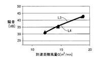
 propeller fan 180 has an air volume that is increased by 40% with respect to the propeller fan 910. Therefore, the propeller fan 180 has a larger air volume than the propeller fan 910 in which the diameter of the propeller fan, the height of the occupied space formed by the rotation of the propeller fan, and the diameter of the boss hub portion are configured identically. It can be seen that it can be obtained.

図56は、プロペラファン180,910の到達距離風量Q(m/min)と、プロペラファン180,910の各々から発生する騒音(dB)との関係を示すグラフである。プロペラファン910の到達距離風量Qと騒音との関係は、線L1によって示される。プロペラファン180の到達距離風量Qと騒音との関係は、線L2によって示される。 FIG. 56 is a graph showing the relationship between the reach air volume Q (m 3 / min) of the propeller fans 180 and 910 and the noise (dB) generated from each of the propeller fans 180 and 910. The relationship between the reach distance air volume Q of the propeller fan 910 and the noise is indicated by a line L1. The relationship between the reach distance air volume Q of the propeller fan 180 and the noise is indicated by a line L2.

線L1および線L2を対比すると、到達距離風量Qが同一の場合、プロペラファン180から発生する騒音は、プロペラファン910から発生する騒音に対して5dB低減している。したがって、プロペラファン180は、プロペラファンの直径、プロペラファンの回転によって形成される占有空間の高さ、および、ボスハブ部の直径がそれぞれ同一に構成されたプロペラファン910に比べて、騒音を低減できることがわかる。   When the line L1 and the line L2 are compared, the noise generated from the propeller fan 180 is reduced by 5 dB with respect to the noise generated from the propeller fan 910 when the reach distance air volume Q is the same. Therefore, the propeller fan 180 can reduce noise as compared with the propeller fan 910 in which the diameter of the propeller fan, the height of the occupied space formed by the rotation of the propeller fan, and the diameter of the boss hub portion are the same. I understand.

図57は、プロペラファン180,910の到達距離風量Q(m/min)と、プロペラファン180,910の各々で使用される消費電力(W)との関係を示すグラフである。プロペラファン910の到達距離風量Qと消費電力との関係は、線L1によって示される。プロペラファン180の到達距離風量Qと消費電力との関係は、線L2によって示される。 FIG. 57 is a graph showing the relationship between the reach distance air volume Q (m 3 / min) of the propeller fans 180 and 910 and the power consumption (W) used in each of the propeller fans 180 and 910. The relationship between the reach distance air volume Q of the propeller fan 910 and the power consumption is indicated by a line L1. The relationship between the reach distance air volume Q of the propeller fan 180 and the power consumption is indicated by a line L2.

線L1および線L2を対比すると、到達距離風量Qが同一の場合、プロペラファン180で使用される消費電力は、プロペラファン910で使用される消費電力に対して5%低減している。したがって、プロペラファン180は、プロペラファンの直径、プロペラファンの回転によって形成される占有空間の高さ、および、ボスハブ部の直径がそれぞれ同一に構成されたプロペラファン910に比べて、消費電力を低減できることがわかる。   When the line L1 and the line L2 are compared, the power consumption used by the propeller fan 180 is reduced by 5% with respect to the power consumption used by the propeller fan 910 when the reach distance air volume Q is the same. Therefore, propeller fan 180 reduces power consumption compared to propeller fan 910 in which the diameter of the propeller fan, the height of the occupied space formed by the rotation of the propeller fan, and the diameter of the boss hub are the same. I understand that I can do it.

[第4検証実験]
図58〜図63を参照して、上記の各実施の形態のプロペラファンに共通して設けられる連結部33に関して行なった第4検証実験について説明する。第4検証実験においては、図58および図59に示すプロペラファン190と、上述の第3検証実験で使用したプロペラファン910(図53および図54参照)とをそれぞれ回転させてその際に得られる風量、騒音、消費電力、および風速分布を測定した。
[Fourth verification experiment]
With reference to FIGS. 58 to 63, a description will be given of a fourth verification experiment performed on the connecting portion 33 provided in common to the propeller fans of the above-described embodiments. In the fourth verification experiment, the propeller fan 190 shown in FIGS. 58 and 59 and the propeller fan 910 (see FIGS. 53 and 54) used in the third verification experiment described above are rotated and obtained at that time. Air volume, noise, power consumption, and wind speed distribution were measured.

図58および図59に示すように、プロペラファン190の基本的な形状としては、上述の第3検証実験で使用したプロペラファン180(図51および図52参照)と略同一である。点線LL3で示されるように、プロペラファン190の翼21は、連結部33の回転方向の中央付近で、かなり深く折れ曲っている。連結部33の負圧面27側に形成される内角は、プロペラファン190の方が、プロペラファン180に比べて小さく形成されている。   As shown in FIGS. 58 and 59, the basic shape of the propeller fan 190 is substantially the same as the propeller fan 180 (see FIGS. 51 and 52) used in the third verification experiment described above. As indicated by a dotted line LL3, the blade 21 of the propeller fan 190 is bent considerably deep near the center of the connecting portion 33 in the rotation direction. The inner angle formed on the suction surface 27 side of the coupling portion 33 is smaller in the propeller fan 190 than in the propeller fan 180.

図60は、プロペラファン190,910の回転数n(rpm)と、プロペラファン190,910の各々から得られる風量Q(m/min)との関係を示すグラフである。プロペラファン910の回転数nと風量Qとの関係は、線L1によって示される。プロペラファン190の回転数nと風量Qとの関係は、線L3によって示される。 FIG. 60 is a graph showing the relationship between the rotational speed n (rpm) of the propeller fans 190 and 910 and the air volume Q (m 3 / min) obtained from each of the propeller fans 190 and 910. The relationship between the rotation speed n of the propeller fan 910 and the air volume Q is indicated by a line L1. The relationship between the rotation speed n of the propeller fan 190 and the air volume Q is indicated by a line L3.

線L1および線L3を対比すると、回転数nが同一の場合、プロペラファン190はプロペラファン910に対して40%増加した風量が得られている。したがって、プロペラファン190は、プロペラファンの直径、プロペラファンの回転によって形成される占有空間の高さ、および、ボスハブ部の直径がそれぞれ同一に構成されたプロペラファン910に比べて、多くの風量を得ることができることがわかる。   Comparing the line L1 and the line L3, when the rotational speed n is the same, the propeller fan 190 has an air volume increased by 40% with respect to the propeller fan 910. Accordingly, the propeller fan 190 has a larger air volume than the propeller fan 910 in which the diameter of the propeller fan, the height of the occupied space formed by the rotation of the propeller fan, and the diameter of the boss hub are the same. It can be seen that it can be obtained.

図61は、プロペラファン190,910の到達距離風量Q(m/min)と、プロペラファン190,910の各々から発生する騒音(dB)との関係を示すグラフである。プロペラファン910の到達距離風量Qと騒音との関係は、線L1によって示される。プロペラファン190の到達距離風量Qと騒音との関係は、線L3によって示される。 FIG. 61 is a graph showing the relationship between the reach air volume Q (m 3 / min) of propeller fans 190 and 910 and the noise (dB) generated from each of propeller fans 190 and 910. The relationship between the reach distance air volume Q of the propeller fan 910 and the noise is indicated by a line L1. The relationship between the reach distance air volume Q of the propeller fan 190 and the noise is indicated by a line L3.

線L1および線L3を対比すると、到達距離風量Qが同一の場合、プロペラファン190から発生する騒音は、プロペラファン910から発生する騒音に対して3dB低減している。したがって、プロペラファン190は、プロペラファンの直径、プロペラファンの回転によって形成される占有空間の高さ、および、ボスハブ部の直径がそれぞれ同一に構成されたプロペラファン910に比べて、騒音を低減できることがわかる。   When the line L1 and the line L3 are compared, the noise generated from the propeller fan 190 is reduced by 3 dB with respect to the noise generated from the propeller fan 910 when the reach distance air volume Q is the same. Therefore, the propeller fan 190 can reduce noise compared to the propeller fan 910 in which the propeller fan diameter, the height of the occupied space formed by the rotation of the propeller fan, and the diameter of the boss hub portion are the same. I understand.

図62は、プロペラファン190,910の到達距離風量Q(m/min)と、プロペラファン190,910の各々で使用される消費電力(W)との関係を示すグラフである。プロペラファン910の到達距離風量Qと消費電力との関係は、線L1によって示される。プロペラファン190の到達距離風量Qと消費電力との関係は、線L3によって示される。 FIG. 62 is a graph showing the relationship between the reach distance air volume Q (m 3 / min) of the propeller fans 190 and 910 and the power consumption (W) used in each of the propeller fans 190 and 910. The relationship between the reach distance air volume Q of the propeller fan 910 and the power consumption is indicated by a line L1. The relationship between the reach distance air volume Q of the propeller fan 190 and the power consumption is indicated by a line L3.

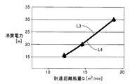
線L1および線L3を対比すると、到達距離風量Qが同一の場合、プロペラファン190で使用される消費電力は、プロペラファン910で使用される消費電力に対して5%低減している。したがって、プロペラファン190は、プロペラファンの直径、プロペラファンの回転によって形成される占有空間の高さ、および、ボスハブ部の直径がそれぞれ同一に構成されたプロペラファン910に比べて、消費電力を低減できることがわかる。   When the line L1 and the line L3 are compared, the power consumption used by the propeller fan 190 is reduced by 5% with respect to the power consumption used by the propeller fan 910 when the reach distance air volume Q is the same. Therefore, propeller fan 190 reduces power consumption compared to propeller fan 910 in which the diameter of the propeller fan, the height of the occupied space formed by the rotation of the propeller fan, and the diameter of the boss hub are the same. I understand that I can do it.

図63は、プロペラファン190,910の各々における中心軸101からの半径方向の距離(無次元)と、風速(無次元)との関係を示すグラフである。プロペラファン910における中心軸101からの半径方向の距離(無次元)と風速(無次元)との関係は、線L1によって示される。プロペラファン190における中心軸101からの半径方向の距離(無次元)と風速(無次元)との関係は、線L3によって示される。   FIG. 63 is a graph showing the relationship between the radial distance (no dimension) from the central axis 101 and the wind speed (no dimension) in each of the propeller fans 190 and 910. The relationship between the radial distance (non-dimensional) from the central axis 101 in the propeller fan 910 and the wind speed (non-dimensional) is indicated by a line L1. The relationship between the radial distance (non-dimensional) from the central axis 101 of the propeller fan 190 and the wind speed (non-dimensional) is indicated by a line L3.

線L1および線L3を対比すると、プロペラファン190,910の双方とも、中心軸101から0.8R(Rは、プロペラファンの平面視における翼21の最大半径)だけ離れた位置で、風速が大きなピーク値を示している。一方で、プロペラファン190においては、中心軸101を中心とする内周側において送風能力を向上させ、中心軸101を中心とする外周側において送風能力を低減させることによって、風速のピークが解消されていることがわかる。   When the line L1 and the line L3 are compared, the wind speed of both the propeller fans 190 and 910 is large at a position separated from the central axis 101 by 0.8R (R is the maximum radius of the blade 21 in a plan view of the propeller fan). The peak value is shown. On the other hand, in the propeller fan 190, the wind speed peak is eliminated by improving the blowing capacity on the inner peripheral side centering on the central axis 101 and reducing the blowing capacity on the outer peripheral side centering on the central axis 101. You can see that

第4検証実験の考察としては、翼面28上に連結部33を設け、翼面28の内側の食い違い角を比較的小さくし、翼面28の外側の食い違い角を比較的大きくし、プロペラファンとしての占有可能空間をほぼ最大限使用しながら鎌形状とすることによって、総風量を大幅に増大させ、騒音および消費電力を低減できることがわかる。   As a consideration of the fourth verification experiment, the connecting portion 33 is provided on the blade surface 28, the misalignment angle inside the blade surface 28 is relatively small, the misalignment angle outside the blade surface 28 is relatively large, and the propeller fan It can be seen that by using a sickle shape while using the occupable space as a maximum, the total air volume can be greatly increased, and noise and power consumption can be reduced.

また、翼面28が連結部33において深く折れ曲がるように形成される場合、連結部33で一旦最大となった食い違い角が外縁部23側で再び増加し、半径方向に沿って切断した翼面28の断面形状は、半径方向に沿って上下する。翼面28が連結部33においてあまり極端に折れ曲がると、その翼面28および連結部33の形状は、翼面28で発生する主流ではない二次流れに影響し、騒音の発生を効果的に抑制するという効果が低下しやすくなる。したがって、占有可能空間内を最大限使用する場合にも、連結部33の近傍での主流および馬蹄渦などの空気流れを考慮し、連結部33の湾曲度合い、屈曲度合い、および形状を定めるとよい。   Further, when the blade surface 28 is formed to be bent deeply at the connecting portion 33, the stagger angle once maximized at the connecting portion 33 is increased again on the outer edge portion 23 side, and the blade surface 28 is cut along the radial direction. The cross-sectional shape of is vertically moved along the radial direction. If the blade surface 28 bends excessively at the connecting portion 33, the shape of the blade surface 28 and the connecting portion 33 affects the secondary flow that is not the mainstream generated on the blade surface 28, and effectively suppresses the generation of noise. The effect of doing tends to decrease. Therefore, even when the occupying space is used to the maximum extent, it is preferable to determine the degree of bending, the degree of bending, and the shape of the connecting portion 33 in consideration of the main flow in the vicinity of the connecting portion 33 and the air flow such as the horseshoe vortex. .

[第5検証実験]
図64〜図68を参照して、上記の各実施の形態のプロペラファンに共通して設けられる連結部33に関して行なった第5検証実験について説明する。第5検証実験においては、図64および図65に示すプロペラファン200と、上述の第4検証実験で使用したプロペラファン190(図58および図59参照)とをそれぞれ回転させてその際に得られる風量、騒音、および消費電力を測定した。
[Fifth verification experiment]
With reference to FIGS. 64-68, the 5th verification experiment performed regarding the connection part 33 provided in common with the propeller fan of said each embodiment is demonstrated. In the fifth verification experiment, the propeller fan 200 shown in FIGS. 64 and 65 and the propeller fan 190 (see FIGS. 58 and 59) used in the fourth verification experiment described above are rotated and obtained at that time. Airflow, noise, and power consumption were measured.

図64および図65に示すように、プロペラファン200の基本的な形状としては、上述の第4検証実験で使用したプロペラファン190(図58および図59参照)と略同一である。点線LL4で示されるように、プロペラファン200の翼21は、連結部33の回転方向の中央付近で緩やかに折れ曲っている。連結部33の負圧面27側に形成される内角は、プロペラファン200の方が、プロペラファン190に比べて大きく形成されている。   As shown in FIGS. 64 and 65, the basic shape of the propeller fan 200 is substantially the same as the propeller fan 190 (see FIGS. 58 and 59) used in the fourth verification experiment described above. As indicated by a dotted line LL4, the blade 21 of the propeller fan 200 is gently bent near the center of the connecting portion 33 in the rotation direction. The inner angle formed on the suction surface 27 side of the connecting portion 33 is larger in the propeller fan 200 than in the propeller fan 190.

プロペラファン200の前縁部22は、プロペラファン190の前縁部22に比べて回転方向の前方側(矢印AR5参照)に延出している。図64中の点線DL5は、プロペラファン190の前縁部22が形成されている位置に相当している。また、連結部33より半径方向の内側の部分の食い違い角は、プロペラファン200の方がプロペラファン190に比べて小さくなるように設けられている。連結部33より半径方向の内側の部分の食い違い角は、プロペラファン190に比べてプロペラファン200の方が、連結部33より半径方向の外側の部分の食い違い角に近い。   The front edge portion 22 of the propeller fan 200 extends to the front side in the rotational direction (see arrow AR5) as compared to the front edge portion 22 of the propeller fan 190. A dotted line DL5 in FIG. 64 corresponds to a position where the front edge portion 22 of the propeller fan 190 is formed. Further, the misalignment angle of the inner portion in the radial direction from the connecting portion 33 is provided such that the propeller fan 200 is smaller than the propeller fan 190. The misalignment angle of the inner portion in the radial direction from the connecting portion 33 is closer to the misalignment angle of the propeller fan 200 than the propeller fan 190 in the portion outside the connecting portion 33 in the radial direction.

図66は、プロペラファン200,190の回転数n(rpm)と、プロペラファン200,190の各々から得られる風量Q(m/min)との関係を示すグラフである。プロペラファン200の回転数nと風量Qとの関係は、線L4によって示される。プロペラファン190の回転数nと風量Qとの関係は、線L3によって示される。線L3および線L4を対比すると、ほとんど違いは見られないことがわかる。 FIG. 66 is a graph showing the relationship between the rotational speed n (rpm) of the propeller fans 200 and 190 and the air volume Q (m 3 / min) obtained from each of the propeller fans 200 and 190. The relationship between the rotation speed n of the propeller fan 200 and the air volume Q is indicated by a line L4. The relationship between the rotation speed n of the propeller fan 190 and the air volume Q is indicated by a line L3. When the lines L3 and L4 are compared, it can be seen that almost no difference is seen.

図67は、プロペラファン200,190の到達距離風量Q(m/min)と、プロペラファン200,190の各々から発生する騒音(dB)との関係を示すグラフである。プロペラファン200の到達距離風量Qと騒音との関係は、線L4によって示される。プロペラファン190の到達距離風量Qと騒音との関係は、線L3によって示される。線L3および線L4を対比すると、ほとんど違いは見られないことがわかる。 FIG. 67 is a graph showing the relationship between the reach distance air volume Q (m 3 / min) of propeller fans 200 and 190 and the noise (dB) generated from each of propeller fans 200 and 190. The relationship between the reach distance air volume Q of the propeller fan 200 and the noise is indicated by a line L4. The relationship between the reach distance air volume Q of the propeller fan 190 and the noise is indicated by a line L3. When the lines L3 and L4 are compared, it can be seen that almost no difference is seen.

図68は、プロペラファン200,190の到達距離風量Q(m/min)と、プロペラファン200,190の各々で使用される消費電力(W)との関係を示すグラフである。プロペラファン200の到達距離風量Qと消費電力との関係は、線L4によって示される。プロペラファン190の到達距離風量Qと消費電力との関係は、線L3によって示される。線L3および線L4を対比すると、ほとんど違いは見られないことがわかる。 FIG. 68 is a graph showing the relationship between the reach distance air volume Q (m 3 / min) of propeller fans 200 and 190 and the power consumption (W) used in each of propeller fans 200 and 190. The relationship between the reach distance air volume Q of the propeller fan 200 and the power consumption is indicated by a line L4. The relationship between the reach distance air volume Q of the propeller fan 190 and the power consumption is indicated by a line L3. When the lines L3 and L4 are compared, it can be seen that almost no difference is seen.

[第6検証実験]
図69〜図73を参照して、上記の各実施の形態のプロペラファンに共通して設けられる連結部33に関して行なった第6検証実験について説明する。第6検証実験においては、図69および図70に示すプロペラファン210と、上述の第4検証実験で使用したプロペラファン190(図58および図59参照)とをそれぞれ回転させてその際に得られる風量、騒音、および消費電力を測定した。
[Sixth verification experiment]
With reference to FIGS. 69 to 73, a sixth verification experiment performed on the connecting portion 33 provided in common to the propeller fans of the above-described embodiments will be described. In the sixth verification experiment, the propeller fan 210 shown in FIGS. 69 and 70 and the propeller fan 190 (see FIGS. 58 and 59) used in the fourth verification experiment described above are rotated and obtained at that time. Airflow, noise, and power consumption were measured.

図69および図70に示すように、プロペラファン210の基本的な形状としては、上述の第4検証実験で使用したプロペラファン190(図58および図59参照)と略同一である。点線LL5で示されるように、プロペラファン210の翼21は、連結部33の回転方向の中央付近で緩やかに折れ曲っている。連結部33の負圧面27側に形成される内角は、プロペラファン210の方が、プロペラファン190に比べて大きく形成されている。   As shown in FIGS. 69 and 70, the basic shape of the propeller fan 210 is substantially the same as the propeller fan 190 (see FIGS. 58 and 59) used in the fourth verification experiment described above. As indicated by a dotted line LL5, the blade 21 of the propeller fan 210 is gently bent near the center of the connecting portion 33 in the rotation direction. The inner angle formed on the negative pressure surface 27 side of the connecting portion 33 is larger in the propeller fan 210 than in the propeller fan 190.

図70中の矢印AR6に示すように、プロペラファン210においては、連結部33の外側の外縁部23が、プロペラファン190のものに比べて噴出側(矢印AR6参照)に位置している。図70中の点線DL6は、プロペラファン190における連結部33の外側の外縁部23が形成されている位置に相当している。連結部33より半径方向の外側の部分の食い違い角は、プロペラファン210の方がプロペラファン190に比べて小さくなるように設けられている。   As shown by an arrow AR6 in FIG. 70, in the propeller fan 210, the outer edge 23 on the outer side of the connecting portion 33 is located on the ejection side (see the arrow AR6) compared to that of the propeller fan 190. A dotted line DL6 in FIG. 70 corresponds to a position where the outer edge portion 23 of the outer side of the connecting portion 33 in the propeller fan 190 is formed. The misalignment angle of the outer portion in the radial direction from the connecting portion 33 is provided so that the propeller fan 210 is smaller than the propeller fan 190.

図71は、プロペラファン210,190の回転数n(rpm)と、プロペラファン210,190の各々から得られる風量Q(m3/min)との関係を示すグラフである。プロペラファン210の回転数nと風量Qとの関係は、線L5によって示される。プロペラファン190の回転数nと風量Qとの関係は、線L3によって示される。   FIG. 71 is a graph showing the relationship between the rotational speed n (rpm) of the propeller fans 210 and 190 and the air volume Q (m3 / min) obtained from each of the propeller fans 210 and 190. The relationship between the rotation speed n of the propeller fan 210 and the air volume Q is indicated by a line L5. The relationship between the rotation speed n of the propeller fan 190 and the air volume Q is indicated by a line L3.

線L3および線L5を対比すると、回転数nが同一の場合、プロペラファン210はプロペラファン190と比べてやや少ないが略同一の風量が得られていることがわかる。したがって、回転数nが同一の場合、プロペラファン190は、上述の第3検証実験で使用したプロペラファン910(図53および図54参照)に対して40%増加した風量が得られている。   Comparing the line L3 and the line L5, it can be seen that when the rotational speed n is the same, the propeller fan 210 obtains substantially the same air volume although it is slightly smaller than the propeller fan 190. Therefore, when the rotation speed n is the same, the propeller fan 190 has an air volume that is increased by 40% with respect to the propeller fan 910 (see FIGS. 53 and 54) used in the third verification experiment described above.

図72は、プロペラファン210,190の到達距離風量Q(m/min)と、プロペラファン210,190の各々から発生する騒音(dB)との関係を示すグラフである。プロペラファン210の到達距離風量Qと騒音との関係は、線L5によって示される。プロペラファン190の到達距離風量Qと騒音との関係は、線L3によって示される。 FIG. 72 is a graph showing the relationship between the reach distance air volume Q (m 3 / min) of the propeller fans 210 and 190 and the noise (dB) generated from each of the propeller fans 210 and 190. The relationship between the reach distance air volume Q of the propeller fan 210 and the noise is indicated by a line L5. The relationship between the reach distance air volume Q of the propeller fan 190 and the noise is indicated by a line L3.

線L5および線L3を対比すると、到達距離風量Qが同一の場合、プロペラファン210から発生する騒音は、プロペラファン190から発生する騒音に対してさらに2dB低減している。したがって、プロペラファン210は、プロペラファンの直径、プロペラファンの回転によって形成される占有空間の高さ、および、ボスハブ部の直径がそれぞれ同一に構成されたプロペラファン190に比べて、騒音をさらに低減できることがわかる。   When the line L5 and the line L3 are compared, the noise generated from the propeller fan 210 is further reduced by 2 dB with respect to the noise generated from the propeller fan 190 when the reach distance air volume Q is the same. Therefore, the propeller fan 210 further reduces noise compared to the propeller fan 190 in which the diameter of the propeller fan, the height of the occupied space formed by the rotation of the propeller fan, and the diameter of the boss hub are the same. I understand that I can do it.

図73は、プロペラファン210,190の到達距離風量Q(m/min)と、プロペラファン210,190の各々で使用される消費電力(W)との関係を示すグラフである。プロペラファン210の到達距離風量Qと消費電力との関係は、線L5によって示される。プロペラファン190の到達距離風量Qと消費電力との関係は、線L3によって示される。 FIG. 73 is a graph showing the relationship between the distance airflow rate Q (m 3 / min) of the propeller fans 210 and 190 and the power consumption (W) used in each of the propeller fans 210 and 190. The relationship between the reach distance air volume Q of the propeller fan 210 and the power consumption is indicated by a line L5. The relationship between the reach distance air volume Q of the propeller fan 190 and the power consumption is indicated by a line L3.

線L5および線L3を対比すると、到達距離風量Qが同一の場合、プロペラファン210で使用される消費電力は、プロペラファン190で使用される消費電力に対してさらに15%低減している。したがって、プロペラファン210は、プロペラファンの直径、プロペラファンの回転によって形成される占有空間の高さ、および、ボスハブ部の直径がそれぞれ同一に構成されたプロペラファン190に比べて、消費電力をさらに低減できることがわかる。   When the line L5 and the line L3 are compared, the power consumption used by the propeller fan 210 is further reduced by 15% with respect to the power consumption used by the propeller fan 190 when the reach distance air volume Q is the same. Therefore, the propeller fan 210 further consumes power compared to the propeller fan 190 in which the diameter of the propeller fan, the height of the occupied space formed by the rotation of the propeller fan, and the diameter of the boss hub are the same. It can be seen that it can be reduced.

第6検証実験の考察としては、プロペラファン210においては、プロペラファンとしての占有可能空間を連結部33より内側では最大限使用し、連結部33より外側では食い違い角をより大きくしている。外縁部23の半径方向外側の高さを下げ、食い違い角が半径方向外側で単調増加していく滑らかな曲面とすることで二次流れが適切に抵抗少なく流れ、乱流および騒音が低減され、消費電力(流れ損失)をも低減可能となることがわかる。   As a consideration of the sixth verification experiment, in the propeller fan 210, the occupable space as the propeller fan is used as much as possible inside the connecting portion 33, and the misalignment angle is made larger outside the connecting portion 33. Lowering the height of the outer edge portion 23 in the radial direction and making it a smooth curved surface in which the stagger angle increases monotonously on the outer side in the radial direction allows the secondary flow to flow with less resistance, reducing turbulence and noise, It can be seen that power consumption (flow loss) can also be reduced.

[第7検証実験]
図74〜図80を参照して、上記の各実施の形態のプロペラファンに共通して設けられる逆キャンバー構造に関して行なった第7検証実験について説明する。第7検証実験においては、図74〜図77に示すプロペラファン220と、上述の第6検証実験で使用したプロペラファン210(図69および図70参照)とをそれぞれ回転させてその際に得られる風量、騒音、および消費電力を測定した。
[Seventh verification experiment]
With reference to FIGS. 74 to 80, a seventh verification experiment performed on the reverse camber structure provided in common to the propeller fans of the above-described embodiments will be described. In the seventh verification experiment, the propeller fan 220 shown in FIGS. 74 to 77 and the propeller fan 210 (see FIGS. 69 and 70) used in the sixth verification experiment described above are rotated and obtained at that time. Airflow, noise, and power consumption were measured.

図74は、プロペラファン220を吸込側から見た斜視図である。図75は、プロペラファン220の側面図である。図76は、図74中のLXXVI−LXXVI線に沿った矢視断面図である。図77は、図74中のLXXVII−LXXVII線に沿った矢視断面図である。   FIG. 74 is a perspective view of the propeller fan 220 as viewed from the suction side. FIG. 75 is a side view of the propeller fan 220. 76 is a cross-sectional view taken along the line LXXVI-LXXVI in FIG. 77 is a cross-sectional view taken along the line LXXVII-LXXVII in FIG.

図74および図75に示すように、プロペラファン220の基本的な形状としては、上述の第6検証実験で使用したプロペラファン210(図69および図70参照)と略同一である。プロペラファン210は逆キャンバー構造を有している。プロペラファン220は逆キャンバー構造を有しておらず、いわゆる正キャンバー構造を有している。   As shown in FIGS. 74 and 75, the basic shape of the propeller fan 220 is substantially the same as the propeller fan 210 (see FIGS. 69 and 70) used in the sixth verification experiment described above. Propeller fan 210 has a reverse camber structure. Propeller fan 220 does not have a reverse camber structure, but has a so-called forward camber structure.

図74〜図76に示すように、プロペラファン220における翼21の内側領域31は、前縁部22および後縁部24を両端として内側領域31の中腹部が仮想直線31Lから吸込側に向かって遠ざかるように湾曲し、翼面28(内側領域31)の正圧面26側が凹となり翼面28(内側領域31)の負圧面27側が凸となるように反った形状を有している。   As shown in FIGS. 74 to 76, in the inner region 31 of the blade 21 in the propeller fan 220, the middle part of the inner region 31 is directed from the virtual straight line 31L toward the suction side with the front edge portion 22 and the rear edge portion 24 as both ends. It has a shape that curves away from each other and warps so that the pressure surface 26 side of the blade surface 28 (inner region 31) is concave and the suction surface 27 side of the blade surface 28 (inner region 31) is convex.

図74、図75、および図77に示すように、プロペラファン220における翼21の外側領域32は、前縁部22および後縁部24を両端として外側領域32の中腹部が仮想直線33Lから吸込側に向かって遠ざかるように湾曲し、翼面28(外側領域32)の正圧面26側が凹となり翼面28(外側領域32)の負圧面27側が凸となるように反った形状を有している。   As shown in FIGS. 74, 75, and 77, in the outer region 32 of the blade 21 in the propeller fan 220, the middle part of the outer region 32 sucks from the virtual straight line 33L with the front edge portion 22 and the rear edge portion 24 as both ends. Curved so that the pressure surface 26 side of the blade surface 28 (outer region 32) is concave and the negative pressure surface 27 side of the blade surface 28 (outer region 32) is convex. Yes.

図76および図77を参照して、プロペラファン220における翼21は、翼根部34および内側領域31において正圧面26側が凹となり負圧面27側が凸となるように反った形状を有し、外側領域32および外縁部23においても正圧面26側が凹となり負圧面27側が凸となるように反った形状を有している(正キャンバー構造)。   76 and 77, the blade 21 in the propeller fan 220 has a warped shape such that the pressure surface 26 side is concave and the suction surface 27 side is convex in the blade root portion 34 and the inner region 31, and the outer region. 32 and the outer edge 23 also have a warped shape such that the pressure surface 26 side is concave and the suction surface 27 side is convex (positive camber structure).

図78は、プロペラファン220,210の回転数n(rpm)と、プロペラファン220,210の各々から得られる風量Q(m/min)との関係を示すグラフである。プロペラファン220の回転数nと風量Qとの関係は、線L6によって示される。プロペラファン210の回転数nと風量Qとの関係は、線L5によって示される。 FIG. 78 is a graph showing the relationship between the rotational speed n (rpm) of the propeller fans 220 and 210 and the air volume Q (m 3 / min) obtained from each of the propeller fans 220 and 210. The relationship between the rotation speed n of the propeller fan 220 and the air volume Q is indicated by a line L6. The relationship between the rotation speed n of the propeller fan 210 and the air volume Q is indicated by a line L5.

線L5および線L6を対比すると、回転数nが同一の場合、プロペラファン220はプロペラファン210と比べてやや少ないが略同一の風量が得られていることがわかる。回転数nが同一の場合、正キャンバー構造を有するプロペラファン220であっても、上述の第3検証実験で使用したプロペラファン910(図53および図54参照)に対して40%増加した風量が得られている。   Comparing the line L5 and the line L6, it can be seen that when the rotational speed n is the same, the propeller fan 220 is slightly smaller than the propeller fan 210 but has substantially the same air volume. When the rotation speed n is the same, even if the propeller fan 220 has a positive camber structure, the air volume increased by 40% over the propeller fan 910 (see FIGS. 53 and 54) used in the third verification experiment described above. Has been obtained.

図79は、プロペラファン220,210の到達距離風量Q(m/min)と、プロペラファン220,210の各々から発生する騒音(dB)との関係を示すグラフである。プロペラファン220の到達距離風量Qと騒音との関係は、線L6によって示される。プロペラファン210の到達距離風量Qと騒音との関係は、線L5によって示される。 FIG. 79 is a graph showing the relationship between the reach distance air volume Q (m 3 / min) of propeller fans 220 and 210 and the noise (dB) generated from each of propeller fans 220 and 210. The relationship between the reach distance air volume Q of the propeller fan 220 and the noise is indicated by a line L6. The relationship between the reach distance air volume Q of the propeller fan 210 and the noise is indicated by a line L5.

線L5および線L6を対比すると、到達距離風量Qが同一の場合、プロペラファン220から発生する騒音は、プロペラファン210から発生する騒音に対してわずかに大きくなることがわかる。到達距離風量Qが同一の場合、正キャンバー構造を有するプロペラファン220であっても、上述の第3検証実験で使用したプロペラファン910(図53および図54参照)に比べると騒音は低減されている。   Comparing the line L5 and the line L6, it can be seen that the noise generated from the propeller fan 220 is slightly larger than the noise generated from the propeller fan 210 when the reach distance air volume Q is the same. When the distance airflow rate Q is the same, even the propeller fan 220 having the positive camber structure has reduced noise compared to the propeller fan 910 (see FIGS. 53 and 54) used in the third verification experiment described above. Yes.

図80は、プロペラファン220,210の到達距離風量Q(m/min)と、プロペラファン220,210の各々で使用される消費電力(W)との関係を示すグラフである。プロペラファン220の到達距離風量Qと消費電力との関係は、線L6によって示される。プロペラファン210の到達距離風量Qと消費電力との関係は、線L5によって示される。 FIG. 80 is a graph showing the relationship between the reach distance air volume Q (m 3 / min) of the propeller fans 220 and 210 and the power consumption (W) used in each of the propeller fans 220 and 210. The relationship between the reach distance air volume Q of the propeller fan 220 and the power consumption is indicated by a line L6. The relationship between the reach distance air volume Q of the propeller fan 210 and the power consumption is indicated by a line L5.

線L5および線L6を対比すると、到達距離風量Qが同一の場合、プロペラファン220で使用される消費電力は、プロペラファン210で使用される消費電力に対してわずかに増加している。到達距離風量Qが同一の場合、正キャンバー構造を有するプロペラファン220であっても、上述の第3検証実験で使用したプロペラファン910(図53および図54参照)に比べると消費電力は低減されている。   When the line L5 and the line L6 are compared, the power consumption used by the propeller fan 220 is slightly increased with respect to the power consumption used by the propeller fan 210 when the reach distance air volume Q is the same. When the distance airflow rate Q is the same, even with the propeller fan 220 having the positive camber structure, the power consumption is reduced compared to the propeller fan 910 (see FIGS. 53 and 54) used in the third verification experiment described above. ing.

第7検証実験の考察としては、風量、騒音、および消費電力の観点では正キャンバー構造に比べると逆キャンバー構造の方が優れていることがわかる。翼面28の高さとコード長さ寸法との関係によっては、翼根部34で送風が良好には行われなくなる場合もあるため、このような場合には、逆キャンバー構造を採用することがよいことがわかる。なお、プロペラファンの直径が180mm、ボスハブ部41の直径が30mm、プロペラファンの回転によって形成される占有空間の中心軸101方向における高さが40mmの場合、正キャンバー構造に比べて逆キャンバー構造の方が顕著に優れた効果が得られることが分かっている。   As a consideration of the seventh verification experiment, it can be seen that the reverse camber structure is superior to the normal camber structure in terms of air volume, noise, and power consumption. Depending on the relationship between the height of the blade surface 28 and the cord length dimension, the blade root portion 34 may not be able to blow air well, and in such a case, it is preferable to employ a reverse camber structure. I understand. In addition, when the propeller fan has a diameter of 180 mm, the boss hub portion 41 has a diameter of 30 mm, and the height of the occupied space formed by the rotation of the propeller fan in the direction of the central axis 101 is 40 mm, the reverse camber structure is compared to the normal camber structure. It has been found that a significantly superior effect is obtained.

図81は、第7検証実験に用いられたプロペラファンの変形例を示す断面図であり、当該変形例のプロペラファンを図76と同一の切断面で切断したときに得られる図である。図81に示すプロペラファン230における翼21の翼根部34のように、中心軸101の周方向に沿う断面視がS字状を呈するように形成されているとよい場合もあることが分かっている。なおこの場合も、翼根部34における食い違い角θAは、外縁部23における食い違い角θBよりも小さく設けられる。   FIG. 81 is a cross-sectional view showing a modified example of the propeller fan used in the seventh verification experiment, and is a view obtained when the propeller fan of the modified example is cut along the same cut surface as FIG. It has been found that there may be a case where the cross-sectional view along the circumferential direction of the central shaft 101 has an S shape like the blade root 34 of the blade 21 in the propeller fan 230 shown in FIG. . In this case as well, the misalignment angle θA at the blade root portion 34 is provided smaller than the misalignment angle θB at the outer edge portion 23.

プロペラファン230の内側領域31は、前縁部22から後縁部24に向かうにつれて、仮想直線31Lから噴出側に向かって離れるようにして湾曲する反った形状と、仮想直線31Lから吸込側に向かって離れるようにして湾曲する反った形状とが、全体としてS字状に連続するように形成されている。翼面28の高さとコード長さ寸法との関係によっては、翼根部34で送風が良好には行われなくなる場合があるため、このような場合には、翼根部34が断面視S字状に形成されていることにより良好な送風が得られる。このような構成(S字キャンバー構造)は、翼面28に連結部33が設けられるという技術的な思想とは独立して実施することが可能である。   The inner region 31 of the propeller fan 230 has a warped shape that curves away from the virtual straight line 31L toward the ejection side as it goes from the front edge 22 to the rear edge 24, and from the virtual straight line 31L toward the suction side. The warped shape that curves away from each other is formed to be continuous in an S shape as a whole. Depending on the relationship between the height of the blade surface 28 and the cord length dimension, the blade root portion 34 may not be able to blow air well. In such a case, the blade root portion 34 has an S-shape in cross section. By being formed, good ventilation can be obtained. Such a configuration (S-shaped camber structure) can be implemented independently of the technical idea that the connecting portion 33 is provided on the blade surface 28.

[実施の形態5]
(流体送り装置610)
図82を参照して、本実施の形態における流体送り装置610について説明する。本実施の形態における流体送り装置610は、たとえば、扇風機として用いられることができる。流体送り装置610は、プロペラファン250と、駆動モータ(図示せず)とを備える。
[Embodiment 5]
(Fluid feeder 610)
With reference to FIG. 82, the fluid feeder 610 in this Embodiment is demonstrated. Fluid feeder 610 in the present embodiment can be used as a fan, for example. The fluid feeder 610 includes a propeller fan 250 and a drive motor (not shown).

(プロペラファン250)
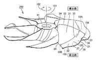
図83は、プロペラファン250を吸込側から見た斜視図である。図84は、プロペラファン250を吸込側から見た平面図である。図85は、プロペラファン250を噴出側から見た斜視図である。図86は、プロペラファン250を噴出側から見た平面図である。図87は、プロペラファン250を示す第1側面図である。図88は、プロペラファン250を示す第2側面図である。
(Propeller fan 250)
FIG. 83 is a perspective view of the propeller fan 250 as seen from the suction side. FIG. 84 is a plan view of the propeller fan 250 as seen from the suction side. FIG. 85 is a perspective view of propeller fan 250 as seen from the ejection side. FIG. 86 is a plan view of propeller fan 250 as seen from the ejection side. 87 is a first side view showing the propeller fan 250. FIG. FIG. 88 is a second side view showing the propeller fan 250.

プロペラファン250は、駆動モータ(図示せず)に駆動されることによって、中心軸101を中心として矢印102に示す方向に回転する。翼21の回転によって風が生成され、流体送り装置610(図82参照)は送風することが可能となる。   Propeller fan 250 rotates in the direction indicated by arrow 102 about central axis 101 by being driven by a drive motor (not shown). Wind is generated by the rotation of the blades 21, and the fluid feeder 610 (see FIG. 82) can blow.

本実施の形態におけるプロペラファン250は、回転軸部としてのボスハブ部41と、7枚の翼21とを有する。プロペラファン250は、7枚以外の複数枚の翼21を備えていてもよいし、1枚のみの翼21を備えていてもよい。プロペラファン250は、扇風機としての流体送り装置610に限られず、サーキュレータ、エアーコンディショナ、空気清浄機、加湿機、除湿機、ファンヒータ、冷却装置、または換気装置などの各種の流体送り装置に用いられることもできる。   Propeller fan 250 in the present embodiment has boss hub portion 41 as a rotating shaft portion and seven blades 21. Propeller fan 250 may include a plurality of blades 21 other than seven, or may include only one blade 21. The propeller fan 250 is not limited to the fluid feeder 610 as a fan, but is used for various fluid feeders such as a circulator, an air conditioner, an air purifier, a humidifier, a dehumidifier, a fan heater, a cooling device, or a ventilator. It can also be done.

ボスハブ部41は、プロペラファン250を、駆動源である駆動モータ(図示せず)の出力軸に接続する部分である。翼21は、ボスハブ部41の外表面から中心軸101の半径方向外側に延出するように形成されている。7枚の翼21は、プロペラファン250の回転軸(中心軸101)の周方向において、等間隔に並んで配置されている。本実施の形態では、7枚の翼21は、同一形状に形成されている。いずれかの翼21を中心軸101を中心に回転させた場合に、その翼21の形状と別の翼21の形状とは一致する。   The boss hub portion 41 is a portion that connects the propeller fan 250 to an output shaft of a drive motor (not shown) that is a drive source. The wings 21 are formed so as to extend outward from the outer surface of the boss hub portion 41 in the radial direction of the central shaft 101. The seven blades 21 are arranged at equal intervals in the circumferential direction of the rotation shaft (center shaft 101) of the propeller fan 250. In the present embodiment, the seven blades 21 are formed in the same shape. When one of the blades 21 is rotated around the central axis 101, the shape of the blade 21 and the shape of another blade 21 are the same.

(翼21)
翼21は、翼根部34および翼根部34から板状に延びる翼面28を含む。翼根部34は、翼21とボスハブ部41の外表面との間(境目)に配置される。翼面28は、正圧面26と、正圧面26の裏側に配置される負圧面27とから構成されている。正圧面26は、中心軸101の軸方向において翼面28の噴出側に位置する。負圧面27は、中心軸101の軸方向において翼面28の吸込側に位置する。正圧面26および負圧面27の各々の表面は、全体として滑らかに形成されている。
(Wings 21)
The blade 21 includes a blade root portion 34 and a blade surface 28 extending from the blade root portion 34 in a plate shape. The blade root portion 34 is disposed between the blade 21 and the outer surface of the boss hub portion 41 (boundary). The blade surface 28 includes a positive pressure surface 26 and a negative pressure surface 27 disposed on the back side of the positive pressure surface 26. The positive pressure surface 26 is located on the ejection side of the blade surface 28 in the axial direction of the central shaft 101. The negative pressure surface 27 is located on the suction side of the blade surface 28 in the axial direction of the central shaft 101. The surfaces of the positive pressure surface 26 and the negative pressure surface 27 are formed smoothly as a whole.

翼面28は、プロペラファン250の回転に伴って送風を行ない、吸込側から噴出側に空気を送り出す。プロペラファン250の回転時、翼面28上で空気流れが発生することに伴って、正圧面26で相対的に大きく、負圧面27で相対的に小さくなる圧力分布が生じる。   The blade surface 28 blows air as the propeller fan 250 rotates, and sends air from the suction side to the ejection side. When the propeller fan 250 rotates, an air flow is generated on the blade surface 28, and a pressure distribution that is relatively large on the positive pressure surface 26 and relatively small on the negative pressure surface 27 is generated.

翼面28の周縁には、翼根部34のうちの回転方向の側の部分から翼根部34のうちの回転方向の反対側の部分に向かって、前縁部22、翼先端部104、外縁部23、翼後端部105、および、後縁部24がこの順で環状に形成される。   At the periphery of the blade surface 28, the leading edge portion 22, the blade tip portion 104, and the outer edge portion are formed from a portion of the blade root portion 34 on the rotation direction side toward a portion of the blade root portion 34 opposite to the rotation direction. 23, the blade trailing end portion 105, and the trailing edge portion 24 are annularly formed in this order.

翼21を平面的に見た場合に、翼21は、前縁部22と外縁部23とが交わる翼先端部104を先端にして、鎌状に尖った形状を有する。前縁部22および後縁部24の径方向内側の部分においては、回転方向に沿ったそれらの幅が徐々に小さくなうように構成されており、前縁部22および後縁部24の径方向外側の部分においては、回転方向に沿ったそれらの幅が徐々に大きくなるように構成されている。   When the wing 21 is viewed in a plane, the wing 21 has a sickle-pointed shape with the wing tip portion 104 where the front edge portion 22 and the outer edge portion 23 cross each other as a tip. The radially inner portions of the front edge portion 22 and the rear edge portion 24 are configured such that their widths along the rotation direction are gradually reduced, and the diameters of the front edge portion 22 and the rear edge portion 24 are reduced. In the outer portion in the direction, the width along the rotation direction is gradually increased.

具体的には、前縁部22は、翼21の回転方向(矢印102方向)の上流側に配置される。プロペラファン250を中心軸101の軸方向から見た場合(換言すると、プロペラファン250を平面的に見た場合)に、前縁部22は、翼根部34のうちの回転方向の側の部分から、中心軸101を中心とする半径方向内側から同方向外側に向けて延びている。前縁部22は、中心軸101を中心とする半径方向内側から同方向外側に湾曲しながら、プロペラファン250の回転方向に向かって延びている。   Specifically, the leading edge portion 22 is disposed on the upstream side in the rotation direction of the blade 21 (the direction of the arrow 102). When the propeller fan 250 is viewed from the axial direction of the central shaft 101 (in other words, when the propeller fan 250 is viewed in a plan view), the leading edge portion 22 is from the portion of the blade root portion 34 in the rotational direction. , Extending from the inner side in the radial direction around the central axis 101 toward the outer side in the same direction. The front edge portion 22 extends in the rotational direction of the propeller fan 250 while curving from the radially inner side around the central axis 101 to the outer side in the same direction.

翼先端部104は、中心軸101から見て前縁部22の半径方向外側に配置される。翼先端部104は、前縁部22と次述する外縁部23とが接続される部分である。本実施の形態における翼先端部104は、翼21の中で最も回転方向の側に位置している。   The blade tip portion 104 is disposed on the radially outer side of the leading edge portion 22 when viewed from the central axis 101. The blade tip 104 is a portion where the front edge 22 and the outer edge 23 described below are connected. The blade tip 104 in the present embodiment is located on the most rotational side of the blade 21.

後縁部24は、翼21の回転方向(矢印102方向)の下流側に配置される。プロペラファン250を中心軸101の軸方向から見た場合(換言すると、プロペラファン250を平面的に見た場合)に、後縁部24は、翼根部34のうちの回転方向の反対側の部分から、中心軸101を中心とする半径方向内側から同方向外側に向けて延びている。後縁部24は、中心軸101を中心とする周方向において、前縁部22と対向して配置されている。後縁部24は、中心軸101を中心とする半径方向内側から同方向外側に緩やかに湾曲しながら、プロペラファン250の回転方向に向かって延びている。   The trailing edge 24 is disposed on the downstream side in the rotation direction of the blade 21 (the direction of the arrow 102). When the propeller fan 250 is viewed from the axial direction of the central shaft 101 (in other words, when the propeller fan 250 is viewed in plan), the trailing edge portion 24 is a portion of the blade root portion 34 on the side opposite to the rotational direction. From the inner side in the radial direction centering on the central axis 101, the outer side extends in the same direction. The rear edge portion 24 is disposed to face the front edge portion 22 in the circumferential direction around the central axis 101. The rear edge 24 extends in the rotational direction of the propeller fan 250 while gently curving from the radially inner side centering on the central axis 101 to the outer side in the same direction.

翼後端部105は、中心軸101から見て後縁部24の半径方向外側に配置される。翼後端部105は、後縁部24と次述する外縁部23とが接続される部分である。本実施の形態のプロペラファン250における翼先端部104は、翼後端部105よりも中心軸101を中心とする内周側に配置されている。   The blade trailing end portion 105 is disposed on the radially outer side of the trailing edge portion 24 when viewed from the central axis 101. The blade trailing end portion 105 is a portion where the trailing edge portion 24 and an outer edge portion 23 described below are connected. The blade tip 104 of the propeller fan 250 of the present embodiment is arranged on the inner peripheral side with the center axis 101 as the center from the blade trailing end 105.

外縁部23は、中心軸101の周方向に沿って延び、翼先端部104と翼後端部105との間を接続するように設けられる。外縁部23は、外縁部23の周方向に延びる線上においてプロペラファン250の最も回転方向の側に位置する翼先端部104で前縁部22と交わり、外縁部23の周方向に延びる線上においてプロペラファン250の最も回転方向の反対側に位置する翼後端部105で後縁部24と交わっている。外縁部23は、全体として、翼先端部104と翼後端部105との間で円弧状に延びている。   The outer edge portion 23 extends along the circumferential direction of the central shaft 101 and is provided so as to connect between the blade tip portion 104 and the blade trailing end portion 105. The outer edge portion 23 intersects the front edge portion 22 at the blade tip portion 104 located on the most rotational direction side of the propeller fan 250 on a line extending in the circumferential direction of the outer edge portion 23, and on the line extending in the circumferential direction of the outer edge portion 23. The blade 250 intersects with the trailing edge 24 at the blade trailing end 105 located on the most opposite side of the rotation direction of the fan 250. The outer edge portion 23 extends in an arc shape between the blade tip portion 104 and the blade trailing end portion 105 as a whole.

前縁部22、翼先端部104、外縁部23、翼後端部105、および、後縁部24は、翼根部34とともに翼21の周縁を形成する周縁部を構成している。この周縁部(前縁部22、翼先端部104、外縁部23、翼後端部105、および、後縁部24)は、いずれも概ね弧状の形状を有するように形成されることで、角部を有さない滑らかな形状とされている。翼面28は、翼根部34とこの周縁部(前縁部22、翼先端部104、外縁部23、翼後端部105、および、後縁部24)とに囲まれた領域の内側の全域に亘って形成されている。   The leading edge portion 22, the blade tip portion 104, the outer edge portion 23, the blade trailing end portion 105, and the trailing edge portion 24 constitute a peripheral portion that forms the peripheral edge of the blade 21 together with the blade root portion 34. The peripheral edge portions (the front edge portion 22, the blade tip portion 104, the outer edge portion 23, the blade rear end portion 105, and the rear edge portion 24) are all formed to have a generally arcuate shape. It has a smooth shape with no part. The blade surface 28 is the entire area inside the region surrounded by the blade root 34 and the peripheral edge (the front edge 22, the blade tip 104, the outer edge 23, the blade rear end 105, and the rear edge 24). It is formed over.

翼面28は、前縁部22から後縁部24に向かう周方向において、吸込側から噴出側に向かって全体として滑らかに湾曲するように形成されている。本実施の形態のプロペラファン250における翼21は、前縁部22と後縁部24とを結ぶ周方向の断面形状の厚みが、前縁部22および後縁部24から翼中心付近に向かうほど厚くなり、翼中心よりも前縁部22側に寄った位置に最大厚みを有する翼型形状を有している。   The blade surface 28 is formed so as to be smoothly curved as a whole from the suction side toward the ejection side in the circumferential direction from the front edge portion 22 toward the rear edge portion 24. In the blade 21 in the propeller fan 250 of the present embodiment, the thickness of the sectional shape in the circumferential direction connecting the leading edge portion 22 and the trailing edge portion 24 increases from the leading edge portion 22 and the trailing edge portion 24 toward the blade center. It is thicker and has an airfoil shape having a maximum thickness at a position closer to the leading edge 22 side than the blade center.

プロペラファン250の翼面28は、内側領域31、外側領域32、および、連結部33を有する。内側領域31、外側領域32、および、連結部33は、正圧面26および負圧面27の双方にそれぞれ形成されている。   The blade surface 28 of the propeller fan 250 has an inner region 31, an outer region 32, and a connecting portion 33. The inner region 31, the outer region 32, and the connecting portion 33 are formed on both the positive pressure surface 26 and the negative pressure surface 27, respectively.

内側領域31は、翼根部34をその一部に含み、連結部33および外側領域32に比べて中心軸101の半径方向の内側に位置する。外側領域32は、翼後端部105をその一部に含み、連結部33および内側領域31に比べて中心軸101の半径方向の外側に位置する。内側領域31における正圧面26の表面形状と、外側領域32における正圧面26の表面形状とは、相互に異なるように形成されている。内側領域31における負圧面27の表面形状と、外側領域32における負圧面27の表面形状とも、相互に異なるように形成されている。   The inner region 31 includes a blade root portion 34 in a part thereof, and is located on the inner side in the radial direction of the central axis 101 compared to the connecting portion 33 and the outer region 32. The outer region 32 includes the blade trailing end portion 105 as a part thereof, and is located on the outer side in the radial direction of the central shaft 101 as compared with the connecting portion 33 and the inner region 31. The surface shape of the pressure surface 26 in the inner region 31 and the surface shape of the pressure surface 26 in the outer region 32 are different from each other. The surface shape of the suction surface 27 in the inner region 31 and the surface shape of the suction surface 27 in the outer region 32 are formed to be different from each other.

連結部33は、翼面28の正圧面26側が凸となり且つ翼面28の負圧面27側が凹となるように、内側領域31と外側領域32とを連結している。連結部33は、概ね回転方向に沿うように設けられており、連結部33のうちの回転方向の最上流側に位置する前端部33Aから、連結部33のうちの回転方向の最下流側に位置する後端部33Bまで延在している。   The connecting portion 33 connects the inner region 31 and the outer region 32 so that the pressure surface 26 side of the blade surface 28 is convex and the negative pressure surface 27 side of the blade surface 28 is concave. The connecting portion 33 is provided substantially along the rotational direction, and from the front end portion 33A located on the most upstream side in the rotating direction of the connecting portion 33 to the most downstream side in the rotating direction of the connecting portion 33. It extends to the rear end portion 33B.

連結部33は、内側領域31から外側領域32に向かうにしたがって翼面28がやや急峻な曲率変化を持って湾曲するようにして形成されており、相互に異なる表面形状を有する内側領域31および外側領域32との境目においてこれら同士を湾曲しながら連結している。連結部33は、これら同士を屈曲しながら連結していてもよい。   The connecting portion 33 is formed such that the blade surface 28 is curved with a slightly steep curvature change from the inner region 31 toward the outer region 32, and the inner region 31 and the outer region having different surface shapes from each other. These are connected while being curved at the boundary with the region 32. The connecting portion 33 may be connected while bending them.

連結部33は、その付近において翼面28の半径方向断面視における曲率が極大となるように設けられており、正圧面26上においては湾曲状に突出した突条部として前端部33Aから後端部33Bに向かって筋状に延びるように現れており、負圧面27上においては湾曲状の窪んだ溝部として前端部33Aから後端部33Bに向かって筋状に延びるように現れている。本実施の形態の連結部33は、翼先端部104から翼後端部105までの途中に位置する外縁部23の部分から、後縁部24まで設けられている。   The connecting portion 33 is provided so that the curvature in the radial cross-sectional view of the blade surface 28 is maximized in the vicinity of the connecting portion 33, and is projected from the front end portion 33 </ b> A to the rear end as a projecting ridge portion protruding on the pressure surface 26. It appears to extend in a streak shape toward the portion 33B, and on the negative pressure surface 27, it appears as a curved concave groove to extend in a streak shape from the front end portion 33A toward the rear end portion 33B. The connecting portion 33 of the present embodiment is provided from the portion of the outer edge portion 23 located in the middle from the blade leading end portion 104 to the blade trailing end portion 105 to the trailing edge portion 24.

本実施の形態における翼21は、いわゆる正キャンバー構造を有する。翼21は、内側領域31および外側領域32の双方において、正圧面26側が凹となり負圧面27側が凸となるように反った形状を有している。翼21は、翼面28のうちの連結部33よりも半径方向内側(内側領域31側)の部分の食い違い角(θA)の方が、翼面28のうちの連結部33よりも半径方向外側(外側領域32側)の部分の食い違い角(θB)よりも小さくなるように形成されている。翼21の外縁部23には、窪み形状の接続部38が設けられている。本実施の形態における窪み形状の接続部38は、外縁部23の翼後端部105寄りの部分から中心軸101側に向けて窪むように形成されている。   The blade 21 in the present embodiment has a so-called positive camber structure. The blade 21 has a curved shape so that the pressure surface 26 side is concave and the negative pressure surface 27 side is convex in both the inner region 31 and the outer region 32. In the blade 21, the stagger angle (θA) of the portion on the radially inner side (on the inner region 31 side) of the connecting portion 33 of the blade surface 28 is radially outward of the connecting portion 33 of the blade surface 28. It is formed so as to be smaller than the stagger angle (θB) of the portion on the (outside region 32 side). The outer edge portion 23 of the wing 21 is provided with a recessed connection portion 38. The recess-shaped connecting portion 38 in the present embodiment is formed so as to be recessed from the portion of the outer edge portion 23 near the blade rear end portion 105 toward the central axis 101 side.

図87および図88には、プロペラファン250の噴出側、すなわち翼21の正圧面26が面する側に、プロペラファン250の回転軸である中心軸101に直交する仮想平面107が示されている。この仮想平面107を基準にして、翼21の後縁部24は、中心軸101を中心とする外周側の領域R3で、外縁部23(翼後端部105)に近づくほど大きくなる高さH3を有する。   87 and 88, an imaginary plane 107 orthogonal to the central axis 101 that is the rotation axis of the propeller fan 250 is shown on the ejection side of the propeller fan 250, that is, the side on which the positive pressure surface 26 of the blade 21 faces. . With reference to this virtual plane 107, the trailing edge 24 of the wing 21 is a region R3 on the outer peripheral side centered on the central axis 101, and becomes a height H3 that increases as it approaches the outer edge 23 (wing trailing edge 105). Have

後縁部24の高さH3は、中心軸101を中心とする内周側で、ボスハブ部41から遠ざかるほど小さくなり、中心軸101を中心とする外周側で、外縁部23(翼後端部105)に近づくほど大きくなる。言い換えれば、後縁部24は、ボスハブ部41と外縁部23との間で、中心軸101の軸方向において噴出側で凸となるように湾曲して延びている。後縁部24の高さH3が外縁部23に近づくほど大きくなり始める位置は、中心軸101を中心に0.4R〜0.7R(Rは、プロペラファン250の平面視における翼21の最大半径)の範囲にあることが好ましい。   The height H3 of the trailing edge portion 24 is smaller on the inner peripheral side centering on the central shaft 101 and is further away from the boss hub portion 41, and on the outer peripheral side centering on the central shaft 101, the outer edge portion 23 (blade rear end portion). 105) the closer it is. In other words, the trailing edge 24 extends between the boss hub 41 and the outer edge 23 so as to be convex on the ejection side in the axial direction of the central axis 101. The position at which the height H3 of the trailing edge 24 starts to increase as it approaches the outer edge 23 is 0.4R to 0.7R (R is the maximum radius of the blade 21 in plan view of the propeller fan 250). ) Is preferable.

(作用・効果)
本実施の形態における流体送り装置610(図1参照)およびプロペラファン250によっても、翼先端部104の近傍で発生し連結部33によって保持されながら流れる翼先端渦と、連結部33の近傍で発生し連結部33によって保持されながら流れる馬蹄渦とが、主流に対して運動エネルギを付与する。運動エネルギを付与された主流は、翼面28上の下流側で翼面28から剥離しにくくなる。結果として、剥離領域を縮小もしくは消滅させることができる。プロペラファン250は、剥離が抑制されることによって、回転時に発生する騒音を低減することができ、連結部33を設けない場合と比較して風量を増加させて高効率化することが可能となる。
(Action / Effect)
The fluid feeder 610 (see FIG. 1) and the propeller fan 250 in the present embodiment also generate the blade tip vortex that is generated in the vicinity of the blade tip portion 104 and is held by the connecting portion 33, and in the vicinity of the connecting portion 33. The horseshoe vortex that flows while being held by the connecting portion 33 gives kinetic energy to the mainstream. The main flow to which kinetic energy is applied is less likely to separate from the blade surface 28 on the downstream side of the blade surface 28. As a result, the peeled area can be reduced or eliminated. Propeller fan 250 can reduce the noise generated at the time of rotation by suppressing the separation, and can increase the air volume and increase the efficiency as compared with the case where connecting portion 33 is not provided. .

窪み形状の接続部38が外縁部23に設けられていることにより、半径方向における風速分布をより均一にすることができ、風速のムラを抑制することが可能となって風当たりの良い風とすることができ、半径方向外側寄りの部分において発生される風に含まれる圧力変動が小さくなる風当たりの良い風を発生させることができ、そして、低速回転時においては、広範囲に拡散する風当たりの良い風とすることができ、高速回転時においては、直進性が高くより遠くへ到達する風とすることができる。   By providing the recess-shaped connecting portion 38 at the outer edge portion 23, the wind speed distribution in the radial direction can be made more uniform, and the unevenness of the wind speed can be suppressed, so that the wind is good. It is possible to generate a wind with good wind perception with a small fluctuation in pressure contained in the wind generated in the radially outward portion, and the wind with good wind spread over a wide range at low speed rotation. In high-speed rotation, it is possible to obtain a wind that has high straightness and reaches farther.

後縁部24の高さH3が外縁部23(翼後端部105)に近づくほど大きくなることにより、中心軸101を中心とする外周側において送風能力を抑制することによって、ファンからの送風の不快感が低減されるプロペラファンを実現することができる。   The height H3 of the trailing edge 24 increases as it approaches the outer edge 23 (blade trailing edge 105), thereby suppressing the blowing capacity on the outer peripheral side with the central axis 101 as the center. A propeller fan with reduced discomfort can be realized.

[第8検証実験]
図89〜図93を参照して、上述の実施の形態5におけるプロペラファン250(図88参照)に関して行った第8検証実験について説明する。第8検証実験においては、上述の実施の形態5におけるプロペラファン250と、図89に示すプロペラファン950とをそれぞれ回転させてその際に得られる風量、騒音、消費電力、および風速分布を測定した。
[Eighth verification experiment]
With reference to FIGS. 89 to 93, an eighth verification experiment performed on propeller fan 250 (see FIG. 88) in the above-described fifth embodiment will be described. In the eighth verification experiment, the propeller fan 250 in the above-described fifth embodiment and the propeller fan 950 shown in FIG. 89 were rotated, and the air volume, noise, power consumption, and wind speed distribution obtained at that time were measured. .

第8検証実験に用いたプロペラファン250の翼21の形状は、上述の第1検証実験で用いられたプロペラファン160(図40および図41参照)と略同一である。連結部33の前端部33Aの無次元位置ηの値は約0.1である。連結部33の後端部33Bの無次元位置ξの値は約0.6である。プロペラファン250の直径は320mmである。プロペラファン250の回転によって形成される占有空間LM50(図88参照)の中心軸101方向における高さは55mmである。ボスハブ部41の直径は70mmである。プロペラファン250と占有空間LM50との間には、所定の体積を有する隙間S1,S2(図88参照)が形成される。内周側の隙間S1の体積は極めて小さく、外周側の隙間S2の体積は多い。   The shape of the blades 21 of the propeller fan 250 used in the eighth verification experiment is substantially the same as the propeller fan 160 (see FIGS. 40 and 41) used in the first verification experiment described above. The dimensionless position η of the front end portion 33A of the connecting portion 33 is about 0.1. The value of the dimensionless position ξ of the rear end portion 33B of the connecting portion 33 is about 0.6. The diameter of the propeller fan 250 is 320 mm. The occupied space LM50 (see FIG. 88) formed by the rotation of the propeller fan 250 has a height in the direction of the central axis 101 of 55 mm. The diameter of the boss hub portion 41 is 70 mm. Between the propeller fan 250 and the occupied space LM50, gaps S1 and S2 (see FIG. 88) having a predetermined volume are formed. The volume of the gap S1 on the inner peripheral side is extremely small, and the volume of the gap S2 on the outer peripheral side is large.

図89を参照して、プロペラファン950は、プロペラファン250と比較して、連結部33を有しておらず、後縁部24の高さが外縁部23(翼後端部105)に近づくほど大きくなるようには形成されていない。プロペラファン950と占有空間LM50との間には、所定の体積を有する隙間S3が形成される。隙間S3の体積は、隙間S1と隙間S2との総和に比べて大きい。その他の点については、プロペラファン950はプロペラファン250と略同様に構成される。   Referring to FIG. 89, propeller fan 950 does not have connecting portion 33 as compared with propeller fan 250, and the height of trailing edge portion 24 approaches outer edge portion 23 (blade trailing end portion 105). It is not formed to be as large as possible. A gap S3 having a predetermined volume is formed between the propeller fan 950 and the occupied space LM50. The volume of the gap S3 is larger than the sum of the gap S1 and the gap S2. In other respects, the propeller fan 950 is configured in substantially the same manner as the propeller fan 250.

図90は、プロペラファン950,250の回転数n(rpm)と、プロペラファン950,250の各々から得られる風量Q(m/min)との関係を示すグラフである。プロペラファン950の回転数nと風量Qとの関係は、線L10によって示される。プロペラファン250の回転数nと風量Qとの関係は、線L20によって示される。 FIG. 90 is a graph showing the relationship between the rotational speed n (rpm) of the propeller fans 950 and 250 and the air volume Q (m 3 / min) obtained from each of the propeller fans 950 and 250. The relationship between the rotational speed n of the propeller fan 950 and the air volume Q is indicated by a line L10. The relationship between the rotation speed n of the propeller fan 250 and the air volume Q is indicated by a line L20.

線L10および線L20を対比すると、回転数nが同一の場合、プロペラファン250はプロペラファン950に対して25%増加した風量が得られている。したがって、プロペラファン250は、プロペラファンの直径、プロペラファンの回転によって形成される占有空間の高さ、および、ボスハブ部の直径がそれぞれ同一に構成されたプロペラファン950に比べて、多くの風量を得ることができることがわかる。   Comparing the line L10 and the line L20, when the rotation speed n is the same, the propeller fan 250 has an air volume that is increased by 25% with respect to the propeller fan 950. Therefore, the propeller fan 250 has a larger air volume than the propeller fan 950 in which the diameter of the propeller fan, the height of the occupied space formed by the rotation of the propeller fan, and the diameter of the boss hub are the same. It can be seen that it can be obtained.

図91は、プロペラファン950,250の到達距離風量Q(m/min)と、プロペラファン950,250の各々から発生する騒音(dB)との関係を示すグラフである。プロペラファン950の到達距離風量Qと騒音との関係は、線L10によって示される。プロペラファン250の到達距離風量Qと騒音との関係は、線L20によって示される。 FIG. 91 is a graph showing the relationship between the reach air volume Q (m 3 / min) of the propeller fans 950 and 250 and the noise (dB) generated from each of the propeller fans 950 and 250. The relationship between the reach distance air volume Q of the propeller fan 950 and the noise is indicated by a line L10. The relationship between the reach distance air volume Q of the propeller fan 250 and the noise is indicated by a line L20.

線L10および線L20を対比すると、到達距離風量Qが同一の場合、プロペラファン250から発生する騒音は、プロペラファン950から発生する騒音に対して8dB低減している。したがって、プロペラファン250は、プロペラファンの直径、プロペラファンの回転によって形成される占有空間の高さ、および、ボスハブ部の直径がそれぞれ同一に構成されたプロペラファン950に比べて、騒音を低減できることがわかる。   When the line L10 and the line L20 are compared, the noise generated from the propeller fan 250 is reduced by 8 dB with respect to the noise generated from the propeller fan 950 when the reach distance air volume Q is the same. Therefore, the propeller fan 250 can reduce noise compared to the propeller fan 950 in which the diameter of the propeller fan, the height of the occupied space formed by the rotation of the propeller fan, and the diameter of the boss hub portion are the same. I understand.

図92は、プロペラファン950,250の到達距離風量Q(m/min)と、プロペラファン950,250の各々で使用される消費電力(W)との関係を示すグラフである。プロペラファン950の到達距離風量Qと消費電力との関係は、線L10によって示される。プロペラファン250の到達距離風量Qと消費電力との関係は、線L20によって示される。 FIG. 92 is a graph showing the relationship between the reach air volume Q (m 3 / min) of propeller fans 950 and 250 and the power consumption (W) used in each of propeller fans 950 and 250. The relationship between the reach distance air volume Q of the propeller fan 950 and the power consumption is indicated by a line L10. The relationship between the range air volume Q of the propeller fan 250 and the power consumption is indicated by a line L20.

線L10および線L20を対比すると、到達距離風量Qが同一の場合、プロペラファン250で使用される消費電力は、プロペラファン950で使用される消費電力よりも小さくなる。たとえば、到達距離風量Qが約50m/minの場合、プロペラファン250で使用される消費電力は、プロペラファン950で使用される消費電力に対して30%低減している。したがって、プロペラファン250は、プロペラファンの直径、プロペラファンの回転によって形成される占有空間の高さ、および、ボスハブ部の直径がそれぞれ同一に構成されたプロペラファン950に比べて、消費電力を低減できることがわかる。 When the line L10 and the line L20 are compared, the power consumption used by the propeller fan 250 is smaller than the power consumption used by the propeller fan 950 when the reach distance air volume Q is the same. For example, when the reach distance air volume Q is about 50 m 3 / min, the power consumption used by the propeller fan 250 is reduced by 30% with respect to the power consumption used by the propeller fan 950. Therefore, the propeller fan 250 reduces power consumption compared to the propeller fan 950 in which the diameter of the propeller fan, the height of the occupied space formed by the rotation of the propeller fan, and the diameter of the boss hub are the same. I understand that I can do it.

図93は、プロペラファン950,250の各々における中心軸101からの半径方向の距離(無次元)と、風速(無次元)との関係を示すグラフである。プロペラファン950における中心軸101からの半径方向の距離(無次元)と風速(無次元)との関係は、線L10によって示される。プロペラファン250における中心軸101からの半径方向の距離(無次元)と風速(無次元)との関係は、線L20によって示される。   FIG. 93 is a graph showing the relationship between the radial distance (no dimension) from the central axis 101 and the wind speed (no dimension) in each of the propeller fans 950 and 250. The relationship between the radial distance (no dimension) from the central axis 101 in the propeller fan 950 and the wind speed (no dimension) is indicated by a line L10. The relationship between the radial distance (no dimension) from the central axis 101 in the propeller fan 250 and the wind speed (no dimension) is indicated by a line L20.

線L10および線L20を対比すると、プロペラファン250は、プロペラファン910に比べて風速のピークが大きく解消され、中心軸101からの半径方向の距離(無次元)が0.1から0.7の範囲ではほぼ完全に風速の均一化が実現できていることがわかる。   When the line L10 and the line L20 are compared, the propeller fan 250 has a larger wind speed peak than the propeller fan 910, and the radial distance from the central axis 101 (dimensionless) is 0.1 to 0.7. In the range, it can be seen that the wind speed is almost completely uniform.

第8検証実験の考察としては、翼面28上に連結部33を設け、翼面28の内側の食い違い角を比較的小さくし、翼面28の外側の食い違い角を比較的大きくし、外縁部23に窪み形状の接続部38を設け、さらに、後縁部24が外周側の領域R3で外縁部23(翼後端部105)に近づくほど大きくなる高さH3を有していることによって、風量の均一化が実現でき、騒音および消費電力を低減できることがわかる。   In consideration of the eighth verification experiment, the connecting portion 33 is provided on the blade surface 28, the misalignment angle inside the blade surface 28 is relatively small, the misalignment angle outside the blade surface 28 is relatively large, and the outer edge portion. 23 has a recess-shaped connecting portion 38, and further has a height H3 that increases as the trailing edge 24 approaches the outer edge 23 (blade trailing end 105) in the outer peripheral region R3. It can be seen that the air volume can be made uniform, and noise and power consumption can be reduced.

図94を参照して、内周側での送風能力をさらに高めるために、プロペラファン260のように、前縁部22から外縁部23の翼先端部104寄りの部分までの領域R1において、中心軸101の軸方向においてこれらが一定の高さを維持するように形成してもよい(上述の実施の形態2参照)。図95を参照して、外周側での送風能力を高めるために、プロペラファン270のように、外縁部23に窪み形状の接続部38を設けない構成としてもよい。図96を参照して、外周側での送風能力を高めるために、プロペラファン280のように、後縁部24が、中心軸101を中心とする外周側の領域R2で、中心軸101の軸方向において一定の高さを有していてもよい(上述の実施の形態3参照)。   Referring to FIG. 94, in order to further enhance the air blowing capability on the inner peripheral side, in the region R1 from the front edge portion 22 to the portion near the blade tip portion 104 of the outer edge portion 23 as in the case of the propeller fan 260, the center You may form so that these may maintain fixed height in the axial direction of the axis | shaft 101 (refer above-mentioned Embodiment 2). Referring to FIG. 95, in order to increase the air blowing capability on the outer peripheral side, a configuration may be adopted in which a recessed connection portion 38 is not provided in the outer edge portion 23 as in the case of the propeller fan 270. Referring to FIG. 96, in order to increase the air blowing capability on the outer peripheral side, like the propeller fan 280, the rear edge 24 is a region R <b> 2 on the outer peripheral side centering on the central axis 101, and the axis of the central axis 101. It may have a certain height in the direction (see Embodiment 3 above).

[実施の形態6]
(成形用金型)
本実施の形態では、上述の各実施の形態および各検証実験における各種のプロペラファンを樹脂を用いて成形するための成形用金型61について説明する。
[Embodiment 6]
(Mold for molding)
In the present embodiment, a molding die 61 for molding various propeller fans in the above-described embodiments and verification experiments using a resin will be described.

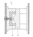
図97は、プロペラファンの製造に用いられる成形用金型を示す断面図である。成形用金型61は、固定側金型62および可動側金型63を有する。固定側金型62および可動側金型63により、プロペラファンと略同一形状であって、流動性の樹脂が注入されるキャビティが規定されている。   FIG. 97 is a cross-sectional view showing a molding die used for manufacturing a propeller fan. The molding die 61 has a fixed side die 62 and a movable side die 63. The fixed side mold 62 and the movable side mold 63 define a cavity that is substantially the same shape as the propeller fan and into which a fluid resin is injected.

成形用金型61には、キャビティに注入された樹脂の流動性を高めるための図示しないヒータが設けられてもよい。このようなヒータの設置は、たとえば、ガラス繊維入りAS樹脂のような強度を増加させた合成樹脂を用いる場合に特に有効である。   The molding die 61 may be provided with a heater (not shown) for enhancing the fluidity of the resin injected into the cavity. The installation of such a heater is particularly effective when, for example, a synthetic resin with increased strength such as an AS resin containing glass fiber is used.

図97中に示す成形用金型61においては、プロペラファンにおける正圧面側表面を固定側金型62によって形成し、負圧面側表面を可動側金型63によって形成することを想定しているが、プロペラファンの負圧面側表面を固定側金型62によって形成し、プロペラファンの正圧面側表面を可動側金型63によって形成してもよい。   In the molding die 61 shown in FIG. 97, it is assumed that the pressure side surface of the propeller fan is formed by the fixed side die 62 and the suction side surface is formed by the movable die 63. Alternatively, the suction surface side surface of the propeller fan may be formed by the stationary mold 62, and the pressure surface side surface of the propeller fan may be formed by the movable mold 63.

プロペラファンとして、材料に金属を用い、プレス加工による絞り成形により一体に形成するものがある。これらの成形は、厚い金属板では絞りが困難であり、質量も重くなるため、一般的には薄い金属板が用いられる。この場合、大きなプロペラファンでは、強度(剛性)を保つことが困難である。これに対して、翼部分より厚い金属板で形成したスパイダーと呼ばれる部品を用い、翼部分を回転軸に固定するものがあるが、質量が重くなり、ファンバランスも悪くなるという問題がある。また、一般的には、薄く、一定の厚みを有する金属板が用いられるため、翼部分の断面形状を翼型にすることができないという問題がある。   Some propeller fans are made of metal as a material and are integrally formed by drawing by press working. In these moldings, a thin metal plate is generally used because it is difficult to draw with a thick metal plate and the mass becomes heavy. In this case, it is difficult to maintain strength (rigidity) with a large propeller fan. On the other hand, there is a part that uses a part called a spider formed of a metal plate thicker than the wing part and fixes the wing part to the rotating shaft, but there is a problem that the mass becomes heavy and the fan balance is also deteriorated. In general, since a thin metal plate having a certain thickness is used, there is a problem in that the cross-sectional shape of the wing portion cannot be a wing shape.

これに対して、プロペラファンを樹脂を用いて形成することにより、これらの問題を一括して解決することができる。   On the other hand, these problems can be solved collectively by forming the propeller fan using a resin.

以上、本発明に基づいた各実施の形態および各検証実験について説明したが、今回開示された各実施の形態および各検証実験はすべての点で例示であって制限的なものではない。本発明の技術的範囲は特許請求の範囲によって示され、特許請求の範囲と均等の意味および範囲内でのすべての変更が含まれることが意図される。   As mentioned above, although each embodiment and each verification experiment based on this invention were demonstrated, each embodiment and each verification experiment which were disclosed this time are an illustration and restrictive at no points. The technical scope of the present invention is defined by the terms of the claims, and is intended to include any modifications within the scope and meaning equivalent to the terms of the claims.

この発明は、たとえば、扇風機、サーキュレータ、エアーコンディショナ、空気清浄機、加湿機、除湿機、ファンヒータ、冷却装置または換気装置などの家庭用電気機器に適用される。   The present invention is applied to household electric appliances such as a fan, a circulator, an air conditioner, an air cleaner, a humidifier, a dehumidifier, a fan heater, a cooling device, or a ventilation device.

21,21A,21B,21C 翼、22 前縁部、23 外縁部、24 後縁部、26 正圧面、27 負圧面、28 翼面、31 内側領域、31L,33L 仮想直線、32 外側領域、33 連結部、33A 前端部、33B 後端部、34 翼根部、38 接続部、41 ボスハブ部(回転軸部)、41S 外表面、52 剥離領域、61 成形用金型、62 固定側金型、63 可動側金型、101 中心軸、102,AR5,AR6 矢印、104 翼先端部、105 翼後端部、107 仮想平面、109 外接円、110,120,120A,130,140,150,160,170,180,190,200,210,220,230,250,260,270,280,910,950 プロペラファン、111 最大径端部、310 主流、320,350 馬蹄渦、330 二次流れ、340 翼先端渦、510,520,610 流体送り装置、800,900 風、C コード長さ寸法、D10,D20 直径、DL5,DL6,L1,L2,L3,L4,L5,L6,L10,L20,LL2,LL3,LL4,LL5 線、H2,H3,H10,H20 高さ、LM1,LM10,LM20,LM50 空間、P1 中心位置、R 半径(最大半径)、R1,R2,R3 領域、S1,S2,S3,SA,SB 隙間、TT 厚さ、Z1 同心円。   21, 21A, 21B, 21C Wings, 22 Front edge, 23 Outer edge, 24 Rear edge, 26 Pressure surface, 27 Pressure surface, 28 Wings surface, 31 Inner region, 31L, 33L Virtual straight line, 32 Outer region, 33 Connecting part, 33A front end part, 33B rear end part, 34 blade root part, 38 connection part, 41 boss hub part (rotating shaft part), 41S outer surface, 52 peeling area, 61 molding die, 62 fixed side mold, 63 Movable side mold, 101 central axis, 102, AR5, AR6 arrow, 104 blade tip, 105 blade trailing edge, 107 virtual plane, 109 circumscribed circle, 110, 120, 120A, 130, 140, 150, 160, 170 , 180, 190, 200, 210, 220, 230, 250, 260, 270, 280, 910, 950 propeller fan, 111 maximum diameter end, 310 Flow, 320, 350 Horseshoe Vortex, 330 Secondary Flow, 340 Wing Tip Vortex, 510, 520, 610 Fluid Feeder, 800, 900 Wind, C Code Length, D10, D20 Diameter, DL5, DL6, L1, L2 , L3, L4, L5, L6, L10, L20, LL2, LL3, LL4, LL5 line, H2, H3, H10, H20 height, LM1, LM10, LM20, LM50 space, P1 center position, R radius (maximum radius ), R1, R2, R3 region, S1, S2, S3, SA, SB gap, TT thickness, Z1 concentric circles.

Claims (5)

仮想の中心軸を中心に所定の回転方向で回転する回転軸部と、
前記回転軸部の外表面から前記中心軸の半径方向外側に延出する翼と、を備え、
前記翼は、
前記翼および前記回転軸部の前記外表面の間に配置される翼根部と、
前記翼根部に連続し、前記翼根部とともに前記翼の周縁を形成する周縁部と、
前記翼根部および前記周縁部に囲まれた領域に形成される翼面と、を含み、
前記周縁部は、
前記回転方向の上流側に配置される前縁部と、
前記前縁部の前記半径方向外側に配置される翼先端部と、
前記回転方向の下流側に配置される後縁部と、
前記後縁部の前記半径方向外側に配置される翼後端部と、
前記中心軸の周方向に延び、前記翼先端部と前記翼後端部との間を接続する外縁部と、を有し、
前記翼面は、
前記翼根部を含み前記半径方向内側に位置する内側領域と、
前記翼後端部を含み前記半径方向外側に位置する外側領域と、
前記前縁部寄り、前記翼先端部寄りまたは前記外縁部寄りに位置する前端部から前記後縁部寄りに位置する後端部まで延在し、前記翼面の正圧面側が凸となり前記翼面の負圧面側が凹となるように前記内側領域と前記外側領域とを連結する連結部と、を有し、
前記連結部は、前記翼先端部から前記翼後端部までの途中に位置する部分から、前記後縁部に向かって延在しており、且つ前記後縁部に到達しない位置にまで設けられ、
前記翼面は、前記翼面のうちの前記連結部よりも前記半径方向外側の部分の食い違い角よりも、前記翼面のうちの前記連結部よりも前記半径方向内側の部分の食い違い角の方が小さくなるように形成され、
前記連結部の前記前端部と前記連結部の前記後端部とを直線で結んだ場合の回転方向における中心位置を通り且つ前記中心軸を中心とする仮想の同心円を描いた場合に、前記連結部の前記前端部は前記同心円の前記半径方向外側に位置する、
プロペラファン。
A rotating shaft portion that rotates in a predetermined rotation direction around a virtual central axis;
A wing extending radially outward of the central axis from the outer surface of the rotating shaft portion,
The wing
A blade root portion disposed between the blade and the outer surface of the rotating shaft portion;
A peripheral portion that is continuous with the blade root and forms a periphery of the blade with the blade root;
A blade surface formed in a region surrounded by the blade root and the peripheral edge,
The peripheral portion is
A front edge portion disposed on the upstream side in the rotational direction;
A blade tip disposed radially outward of the leading edge;
A rear edge disposed downstream in the rotational direction;
A wing trailing end disposed on the radially outer side of the trailing edge; and
An outer edge portion extending in a circumferential direction of the central axis and connecting between the blade tip portion and the blade trailing end portion;
The wing surface is
An inner region that includes the blade root and is located radially inward;
An outer region located radially outward including the wing trailing edge;
The blade surface extends from the front end portion located near the front edge portion, the blade tip portion or the outer edge portion to the rear end portion located near the rear edge portion, and the pressure surface side of the blade surface is convex. A connecting portion that connects the inner region and the outer region so that the suction surface side of the
The connecting portion extends from a portion located midway from the blade tip to the blade trailing end, and extends to the trailing edge, and is provided at a position not reaching the trailing edge. ,
The blade surface has a misalignment angle of a portion of the blade surface radially inward of the connecting portion and a misalignment angle of the portion of the blade surface radially inward of the connecting portion. Is formed to be small,
When the front end portion of the connecting portion and the rear end portion of the connecting portion are connected by a straight line, a virtual concentric circle passing through the center position in the rotation direction and centering on the central axis is drawn. The front end of the part is located radially outward of the concentric circles;
Propeller fan.
前記翼面は、前記翼面のうちの前記連結部よりも前記半径方向内側の部分の翼面積が、前記翼面のうちの前記連結部よりも前記半径方向外側の部分の翼面積と同一若しくはこれよりも大きくなるように形成されている、
請求項1に記載のプロペラファン。
In the blade surface, the blade area of the radially inner portion of the blade surface with respect to the connecting portion is the same as the blade area of the radially outer portion of the blade surface with respect to the connecting portion, or It is formed to be larger than this,
The propeller fan according to claim 1.
前記連結部は、前記連結部の前記負圧面側に形成される内角が、前記回転方向における前記連結部の中心付近で最も小さくなるように形成される、
請求項1または2に記載のプロペラファン。
The connecting portion is formed such that an inner angle formed on the suction surface side of the connecting portion is the smallest in the vicinity of the center of the connecting portion in the rotation direction.
The propeller fan according to claim 1 or 2.
請求項1から3のいずれかに記載のプロペラファンを備える、
流体送り装置。
The propeller fan according to claim 1 is provided.
Fluid feeder.
請求項1から3のいずれかに記載のプロペラファンは樹脂成形品からなり、
前記プロペラファンを成形するために用いられる、
成形用金型。
The propeller fan according to any one of claims 1 to 3 is a resin molded product,
Used to mold the propeller fan,
Mold for molding.
JP2014204963A 2014-10-03 2014-10-03 Propeller fan, fluid feeder and mold Active JP6141247B2 (en)

Priority Applications (1)

Application Number Priority Date Filing Date Title
JP2014204963A JP6141247B2 (en) 2014-10-03 2014-10-03 Propeller fan, fluid feeder and mold

Applications Claiming Priority (1)

Application Number Priority Date Filing Date Title
JP2014204963A JP6141247B2 (en) 2014-10-03 2014-10-03 Propeller fan, fluid feeder and mold

Related Parent Applications (1)

Application Number Title Priority Date Filing Date
JP2012089282A Division JP5629720B2 (en) 2012-04-10 2012-04-10 Propeller fan, fluid feeder and mold

Publications (3)

Publication Number Publication Date
JP2015017616A JP2015017616A (en) 2015-01-29
JP2015017616A5 JP2015017616A5 (en) 2015-04-23
JP6141247B2 true JP6141247B2 (en) 2017-06-07

Family

ID=52438807

Family Applications (1)

Application Number Title Priority Date Filing Date
JP2014204963A Active JP6141247B2 (en) 2014-10-03 2014-10-03 Propeller fan, fluid feeder and mold

Country Status (1)

Country Link
JP (1) JP6141247B2 (en)

Families Citing this family (3)

* Cited by examiner, † Cited by third party
Publication number Priority date Publication date Assignee Title
JP6381794B2 (en) * 2015-05-11 2018-08-29 三菱電機株式会社 Axial blower
KR101745904B1 (en) * 2016-10-19 2017-06-13 주식회사 한미마이크로닉스 Cooler fan having double blade
WO2020031800A1 (en) * 2018-08-06 2020-02-13 シャープ株式会社 Propeller fan and air blowing device

Family Cites Families (8)

* Cited by examiner, † Cited by third party
Publication number Priority date Publication date Assignee Title
JPH05202893A (en) * 1992-01-30 1993-08-10 Matsushita Electric Ind Co Ltd Air blower
JP3203994B2 (en) * 1994-10-31 2001-09-04 三菱電機株式会社 Axial blower
JP3483447B2 (en) * 1998-01-08 2004-01-06 松下電器産業株式会社 Blower
JP4132826B2 (en) * 2002-01-10 2008-08-13 シャープ株式会社 Propeller fan, its mold and fluid feeder
JP2007113474A (en) * 2005-10-20 2007-05-10 Mitsubishi Electric Corp Blower
JP4797776B2 (en) * 2006-04-24 2011-10-19 パナソニック株式会社 Mixed flow blower impeller and air conditioner
JP5211813B2 (en) * 2008-04-10 2013-06-12 パナソニック株式会社 Ceiling fan
JP5210852B2 (en) * 2008-12-22 2013-06-12 山洋電気株式会社 Axial blower

Also Published As

Publication number Publication date
JP2015017616A (en) 2015-01-29

Similar Documents

Publication Publication Date Title
WO2013154102A1 (en) Propeller fan, fluid sending device, and mold for molding
US10544797B2 (en) Propeller fan, fluid feeder, electric fan, and molding die
JP4798640B2 (en) Propeller fan, molding die and fluid feeder
JP4388992B1 (en) Propeller fan, fluid feeder and mold
JP6154990B2 (en) Propeller fan for electric fan, electric fan equipped with the same, and mold for molding propeller fan for electric fan
EP2383473B1 (en) Propeller fan
JP5629721B2 (en) Propeller fan, fluid feeder and mold
JP5631353B2 (en) Propeller fan, fluid feeder and mold
JP6141247B2 (en) Propeller fan, fluid feeder and mold
JP5629720B2 (en) Propeller fan, fluid feeder and mold
JP6058276B2 (en) Propeller fan, fluid feeder and mold
JP6068720B2 (en) Electric fan or circulator propeller fan, electric fan or circulator, and mold
JP5697465B2 (en) Propeller fan, molding die and fluid feeder
JP6050297B2 (en) Propeller fan and mold
JP6088702B2 (en) Electric fan or circulator propeller fan, electric fan or circulator, and mold
JP6143725B2 (en) Propeller fan, fluid feeder and mold
JP6644026B2 (en) Propeller fan, fluid feeder having the same, and molding die for propeller fan
CN208252427U (en) A kind of impeller
JP6084368B2 (en) Propeller fan, fluid feeder including the same, electric fan, and mold for forming propeller fan
WO2020031800A1 (en) Propeller fan and air blowing device
CN108757558A (en) A kind of impeller

Legal Events

Date Code Title Description
A521 Written amendment

Free format text: JAPANESE INTERMEDIATE CODE: A523

Effective date: 20150310

A621 Written request for application examination

Free format text: JAPANESE INTERMEDIATE CODE: A621

Effective date: 20150310

A131 Notification of reasons for refusal

Free format text: JAPANESE INTERMEDIATE CODE: A131

Effective date: 20160531

A521 Written amendment

Free format text: JAPANESE INTERMEDIATE CODE: A523

Effective date: 20160721

A02 Decision of refusal

Free format text: JAPANESE INTERMEDIATE CODE: A02

Effective date: 20161129

A521 Written amendment

Free format text: JAPANESE INTERMEDIATE CODE: A523

Effective date: 20170217

A911 Transfer of reconsideration by examiner before appeal (zenchi)

Free format text: JAPANESE INTERMEDIATE CODE: A911

Effective date: 20170302

TRDD Decision of grant or rejection written
A01 Written decision to grant a patent or to grant a registration (utility model)

Free format text: JAPANESE INTERMEDIATE CODE: A01

Effective date: 20170411

A61 First payment of annual fees (during grant procedure)

Free format text: JAPANESE INTERMEDIATE CODE: A61

Effective date: 20170502

R150 Certificate of patent or registration of utility model

Ref document number: 6141247

Country of ref document: JP

Free format text: JAPANESE INTERMEDIATE CODE: R150