EP3342960A1 - Vehicle inspection system, method and smart garage - Google Patents
Vehicle inspection system, method and smart garage Download PDFInfo
- Publication number
- EP3342960A1 EP3342960A1 EP17210393.9A EP17210393A EP3342960A1 EP 3342960 A1 EP3342960 A1 EP 3342960A1 EP 17210393 A EP17210393 A EP 17210393A EP 3342960 A1 EP3342960 A1 EP 3342960A1
- Authority
- EP
- European Patent Office
- Prior art keywords
- carrier platform
- vehicle
- inspection
- inspected
- controlled travelling
- Prior art date
- Legal status (The legal status is an assumption and is not a legal conclusion. Google has not performed a legal analysis and makes no representation as to the accuracy of the status listed.)
- Granted
Links
Images

Classifications
-
- E—FIXED CONSTRUCTIONS
- E04—BUILDING
- E04H—BUILDINGS OR LIKE STRUCTURES FOR PARTICULAR PURPOSES; SWIMMING OR SPLASH BATHS OR POOLS; MASTS; FENCING; TENTS OR CANOPIES, IN GENERAL
- E04H6/00—Buildings for parking cars, rolling-stock, aircraft, vessels or like vehicles, e.g. garages
- E04H6/08—Garages for many vehicles
- E04H6/12—Garages for many vehicles with mechanical means for shifting or lifting vehicles
- E04H6/30—Garages for many vehicles with mechanical means for shifting or lifting vehicles with means for transport in horizontal direction only
- E04H6/36—Garages for many vehicles with mechanical means for shifting or lifting vehicles with means for transport in horizontal direction only characterised by use of freely-movable dollies
-
- E—FIXED CONSTRUCTIONS
- E04—BUILDING
- E04H—BUILDINGS OR LIKE STRUCTURES FOR PARTICULAR PURPOSES; SWIMMING OR SPLASH BATHS OR POOLS; MASTS; FENCING; TENTS OR CANOPIES, IN GENERAL
- E04H6/00—Buildings for parking cars, rolling-stock, aircraft, vessels or like vehicles, e.g. garages
- E04H6/42—Devices or arrangements peculiar to garages, not covered elsewhere, e.g. securing devices, safety devices, monitoring and operating schemes; centering devices
-
- B—PERFORMING OPERATIONS; TRANSPORTING
- B65—CONVEYING; PACKING; STORING; HANDLING THIN OR FILAMENTARY MATERIAL
- B65G—TRANSPORT OR STORAGE DEVICES, e.g. CONVEYORS FOR LOADING OR TIPPING, SHOP CONVEYOR SYSTEMS OR PNEUMATIC TUBE CONVEYORS
- B65G47/00—Article or material-handling devices associated with conveyors; Methods employing such devices
- B65G47/74—Feeding, transfer, or discharging devices of particular kinds or types
- B65G47/90—Devices for picking-up and depositing articles or materials
-
- B—PERFORMING OPERATIONS; TRANSPORTING
- B65—CONVEYING; PACKING; STORING; HANDLING THIN OR FILAMENTARY MATERIAL
- B65G—TRANSPORT OR STORAGE DEVICES, e.g. CONVEYORS FOR LOADING OR TIPPING, SHOP CONVEYOR SYSTEMS OR PNEUMATIC TUBE CONVEYORS
- B65G67/00—Loading or unloading vehicles
- B65G67/02—Loading or unloading land vehicles
-
- E—FIXED CONSTRUCTIONS
- E04—BUILDING
- E04H—BUILDINGS OR LIKE STRUCTURES FOR PARTICULAR PURPOSES; SWIMMING OR SPLASH BATHS OR POOLS; MASTS; FENCING; TENTS OR CANOPIES, IN GENERAL
- E04H6/00—Buildings for parking cars, rolling-stock, aircraft, vessels or like vehicles, e.g. garages
- E04H6/08—Garages for many vehicles
- E04H6/12—Garages for many vehicles with mechanical means for shifting or lifting vehicles
- E04H6/30—Garages for many vehicles with mechanical means for shifting or lifting vehicles with means for transport in horizontal direction only
- E04H6/34—Garages for many vehicles with mechanical means for shifting or lifting vehicles with means for transport in horizontal direction only characterised by use of movable platforms
-
- E—FIXED CONSTRUCTIONS
- E04—BUILDING
- E04H—BUILDINGS OR LIKE STRUCTURES FOR PARTICULAR PURPOSES; SWIMMING OR SPLASH BATHS OR POOLS; MASTS; FENCING; TENTS OR CANOPIES, IN GENERAL
- E04H6/00—Buildings for parking cars, rolling-stock, aircraft, vessels or like vehicles, e.g. garages
- E04H6/42—Devices or arrangements peculiar to garages, not covered elsewhere, e.g. securing devices, safety devices, monitoring and operating schemes; centering devices
- E04H6/422—Automatically operated car-parks
-
- B—PERFORMING OPERATIONS; TRANSPORTING
- B65—CONVEYING; PACKING; STORING; HANDLING THIN OR FILAMENTARY MATERIAL
- B65G—TRANSPORT OR STORAGE DEVICES, e.g. CONVEYORS FOR LOADING OR TIPPING, SHOP CONVEYOR SYSTEMS OR PNEUMATIC TUBE CONVEYORS
- B65G2201/00—Indexing codes relating to handling devices, e.g. conveyors, characterised by the type of product or load being conveyed or handled
- B65G2201/02—Articles
- B65G2201/0294—Vehicle bodies
-
- B—PERFORMING OPERATIONS; TRANSPORTING
- B65—CONVEYING; PACKING; STORING; HANDLING THIN OR FILAMENTARY MATERIAL
- B65G—TRANSPORT OR STORAGE DEVICES, e.g. CONVEYORS FOR LOADING OR TIPPING, SHOP CONVEYOR SYSTEMS OR PNEUMATIC TUBE CONVEYORS
- B65G2813/00—Indexing codes relating to transport for special purposes
-
- B—PERFORMING OPERATIONS; TRANSPORTING
- B65—CONVEYING; PACKING; STORING; HANDLING THIN OR FILAMENTARY MATERIAL
- B65G—TRANSPORT OR STORAGE DEVICES, e.g. CONVEYORS FOR LOADING OR TIPPING, SHOP CONVEYOR SYSTEMS OR PNEUMATIC TUBE CONVEYORS
- B65G2814/00—Indexing codes relating to loading or unloading articles or bulk materials
- B65G2814/03—Loading or unloading means
- B65G2814/0301—General arrangements
- B65G2814/0311—Other article loading or unloading devices
- B65G2814/0313—Other article loading or unloading devices with vertically reciprocating platforms
Definitions
- the present disclosure relates to the field of safety inspection, and more particularly to an vehicle inspection system and a method and a smart garage.
- This smart garage often includes a multistorey, three-dimensional garage that is capable of automatically conveying a vehicle of a user to a designated parking position by intelligent control, and conveying the vehicle of the user to a designated return location when the user retrieves the vehicle.
- the object of the present disclosure is to propose an vehicle inspection system, a method and a smart garage which can conveniently realize inspection of a vehicle and avoid scanning a driver.
- an vehicle inspection system comprising:
- the unmanned controlled travelling device comprises:
- the carrier platform is configured to contain the unmanned controlled travelling device under the carrier platform ; the vertical driving mechanism comprising a lifting mechanism, for moving the carrier platform off the ground when the unmanned controlled travelling device is located under the carrier platform.
- the horizontal driving mechanism comprises a dragging mechanism with a connecting piece, for connecting the connecting piece with the carrier platform, and dragging the carrier platform across the scanning area of the inspection device by movement of the vehicle body.
- the unmanned controlled travelling device is an Automated Guided Vehicle.
- the carrier platform comprises a platform body and a support portion, the support portion is provided under the platform body, and supportable on the ground, for forming a space accommodating entry of the unmanned controlled travelling device.
- a vertically penetrating through-hole is provided on the middle of the platform body, and the inspection device is a top radiation scanning inspection device, for forming a scanning area from top to bottom.
- a smart garage comprising:
- the unmanned controlled travelling device is configured to convey the empty carrier platform to the loading station , so that the vehicle to be inspected travels on its own or is driven to the carrier platform ; the unmanned controlled travelling device is configured to move to the parking area of a vehicle to be unloaded upon receiving a loading instruction, and drive the carrier platform carrying the vehicle to be unloaded to move to the unloading station.
- an automatic vehicle inspection method comprising:
- the another target area is a designated parking area or an exit for safety inspection area corresponding to the vehicle to be inspected.
- the unmanned controlled travelling device comprises a vehicle body, a vertical driving mechanism and a horizontal driving mechanism, wherein the vertical driving mechanism and the horizontal driving mechanism are disposed on the vehicle body; the step that the unmanned controlled travelling device drives the carrier platform to pass through a scanning area of the inspection device comprises:
- the vertical driving mechanism comprises a lifting mechanism, such that the carrier platform contains the unmanned controlled travelling device under the carrier platform when the carrier platform is located on the ground, and the unmanned controlled travelling device moves the carrier platform off the ground by the lifting mechanism under the carrier platform.
- the unmanned controlled travelling device moves to the parking area of a vehicle to be unloaded, and drives the carrier platform carrying the vehicle to be unloaded to move to the unloading station.
- the vehicles to be inspected is carried by the carrier platform, and the unmanned controlled walking device is used to move the carrier platform to pass through the scanning area of the inspection device, so that the vehicle to be inspected can be carried out inspection smoothly.
- the unmanned controlled walking device is used to move the carrier platform to pass through the scanning area of the inspection device, so that the vehicle to be inspected can be carried out inspection smoothly.
- There is no driver required to drive through the scanning area in this process thus avoiding exposure of a driver to a threat of radiation.
- movement of the carrier platform is driven by the unmanned controlled walking device, compared to a conveyor, civil engineering construction may be omitted, while the inspection device may also be relocated at any time, thereby improving the flexibility and applicability of the automatic vehicle inspection system.
- the smart garage first includes a parking area C that parks a plurality of carrier platforms 2 or vehicles, and also includes an vehicle inspection system for the vehicles which enter the garage for parking.
- a plurality of parking spaces located at the parking area C may include an ordinary vehicle, and may also include a carrier platform 2 that supports an ordinary vehicle.
- These parking spaces may be provided in such a form as to be adapted for parking an ordinary vehicle and a carrier platform 2 at the same time, and may also set their respective form suitable for parking.
- the vehicle inspection system may specifically comprise: an inspection device 9, a carrier platform 2 and an unmanned controlled travelling device.
- the inspection device 9 is used for performing inspection of a vehicle 4 to be inspected, such as a non-contact inspection system and the like, which performs scanning imaging of the vehicle to be inspected by radiation, so as to identify whether the vehicle to be inspected internally carriers dangerous goods.
- the carrier platform 2 is used for carrying vehicles. It can park at the parking area and stably support the vehicles.
- the unmanned controlled travelling device is responsible for driving the carrier platform 2 through the scanning area of the inspection device 9.
- the carrier platform 2 and the vehicle 4 to be inspected carried are both driven by the unmanned controlled travelling device to move, and to further accomplish such a process as to pass through the scanning area of the inspection device 9.
- the unmanned controlled travelling device may also drive the carrier platform 2 to move within a movement area of the carrier platform 2.
- the carrier platform 2 is conveyed to the parking area C, or when it is necessary to have a vehicle unloaded, the carrier platform 2 carrying the vehicle to be unloaded 5 is conveyed to the unloading station D.
- an empty carrier platform 2 is conveyed to the loading station A or the like.
- the unmanned controlled travelling device may use an unmanned travelling device that is remotely controlled or automatically controlled.
- an Automated Guided Vehicle AGV its accessible range may be inside the smart garage, to effectuate entry and exit of vehicles.
- AGV can flexibly drive the carrier platform to move forward/backward, turn or translate, so as to realize motion of a single AGV as well as movement across of a plurality of AGVs within the accessible range.
- the vehicle to be inspected is carried by the carrier platform and the unmanned controlled travelling device is used to drive the carrier platform to pass through the scanning area of the inspection device, so that the vehicle to be inspected can be carried out inspection smoothly, thus improving the passing rate of vehicles.
- the unmanned controlled travelling device is used to drive the carrier platform to pass through the scanning area of the inspection device, so that the vehicle to be inspected can be carried out inspection smoothly, thus improving the passing rate of vehicles.
- There is no driver required to drive through the scanning area in this process thus avoiding a threat that the driver is exposed to radiation.
- civil engineering construction may be omitted, while the inspection device may also be relocated at any time, thereby improving the flexibility and applicability of the vehicle inspection system.
- a ramp 6 may be provided at the loading station A (for example, entrance of a smart garage), so that the vehicle 4 to be inspected can reach an upper surface of the carrier platform 2 through a top of the ramp 6. This process may be accomplished by driver driving, and may also be realized by other traction tools or driving programs.
- a depressed tunnel may also be provided at the loading station A. When the carrier platform 2 is in the tunnel, the upper surface thereof is flush with the ground, so that the vehicle 4 to be inspected directly moves to the upper surface of the carrier platform 2.
- a ramp 6 may also be provided at the unloading station D (such as an outlet of the intelligent garage and the like), so that the vehicle 5 to be unloaded can leave the carrier platform 2 from the upper surface of the carrier platform 2 via the ramp 6.
- This process may be accomplished by driver driving, and may also be realized by other traction tools or driving programs.
- a depressed tunnel may also be provided at the unloading station D. When the carrier platform 2 is in the tunnel, the upper surface thereof is flush with the ground, so that the vehicle 5 to be unloaded directly moves to the ground from the upper surface of the carrier platform 2.
- the driving manner of the unmanned controlled travelling device for the carrier platform is also different.
- the unmanned controlled travelling device always drives the carrier platform to move on the ground, and pass through the scanning area in a dragging manner; or the unmanned controlled travelling device drives the carrier platform to move on the ground, and pass through the scanning area in a pushing manner.
- the unmanned controlled travelling device backs up the carrier platform to move on the ground, and pass through the scanning area in a supporting manner; or the unmanned controlled travelling device backs up the carrier platform to move on the ground in a supporting manner, and drives the carrier platform to pass through the scanning area in a dragging or pulling manner.
- the unmanned controlled travelling device has such two carrier platform driving manners as a vertically supporting carrier platform and a horizontally driving carrier platform.
- the unmanned controlled travelling device includes a vehicle body, a vertical driving mechanism and a horizontal driving mechanism.
- the vertical driving mechanism is provided on the vehicle body, for moving the carrier platform 2 off the ground or placing the carrier platform 2 on the ground.
- the horizontal driving mechanism is also provided on the vehicle body, for driving the carrier platform 2 to pass across a scanning area of the inspection device 9.
- the vehicle body is used for travelling under remote control, and carrying the carrier platform 2.
- Such carrying may be a direct supporting effect of the vehicle body over the lower surface of the carrier platform 2, and may also be an indirect supporting effect of the carrier platform 2 by means of the vertical driving mechanism.
- a space capable of accommodating entry of the unmanned controlled travelling device is preferably formed under the carrier platform 2.
- the carrier platform 2 may comprise a platform body and a support portion which is provided under the platform body, is supportable on the ground, and forms a space accommodating entry of the unmanned controlled travelling device.
- the vertical driving mechanism includes a lifting mechanism capable of moving the carrier platform 2 off the ground when the unmanned controlled travelling device is located under the carrier platform 2.
- the unmanned controlled travelling device when there is a need for the unmanned controlled travelling device to back up the carrier platform 2 to move on the ground in a supporting manner, it is possible to first allow the unmanned controlled travelling device to enter the lower space of the carrier platform 2, and then utilizing the lifting mechanism to uphold the carrier platform 2 upwards, such that the unmanned controlled travelling device may drive the carrier platform 2 and even the vehicle carried thereon to move together by means of own motion.
- the horizontal driving mechanism includes a dragging mechanism with a connecting piece (for example, a connecting pin 8 in Figure 2 ), which is capable of connecting the connecting piece with the carrier platform 2, and dragging the carrier platform 2 across the scanning area of the inspection device 9 by movement of the vehicle body.
- a connecting piece for example, a connecting pin 8 in Figure 2
- the horizontal driving mechanism may also be a pushing mechanism that imparts a pushing force to the carrier platform 2.
- the AGV 1 as an unmanned controlled travelling device, may support the carrier platform 2 in advance and wait for the vehicle 4 to be inspected at the loading station A.
- the AGV 1 in a state of supporting the carrier platform 2, carries the carrier platform 2 and the vehicle 4 to be inspected to move to the inspection station B.
- the inspection station e.g. one side of the inspection device 9
- the lifting mechanism of the AGV 1 lowers the carrier platform 2 until the supporting ground.
- the AGV 1 no longer forms a support for the carrier platform 2 and then the AGV 1 moves out from under the carrier platform 2, and one end of the AGV 1 is connected to one end of the carrier platform 2 by means of the connecting pin 8 (for example, corresponding to one end at the front or rear of the vehicle 4 to be inspected).
- the inspection process is the process that the AGV 1 drags the carrier platform 2 and the vehicle 4 to be inspected to pass across the scanning area of the inspection device 9. Since the AGV 1 is outside the scanning area when the vehicle 4 to be inspected is scanned, the AGV 1 can shield the vehicle image as less as possible, so as not to significantly affect the scanning result of the vehicle 4 to be inspected.
- the scanning area may be provided according to the structural form, principles and performance of the inspection device. Considering the circumstance that an article in the vehicle to be inspected can be more clearly inspected from the top, it is preferable to use a top radiation scanning inspection device 9, capable of forming a scanning area from top to bottom. In order to facilitate receiving the radiation penetrating through the vehicle, it is preferable to provide a vertically penetrating through-hole 7 on the middle of the platform body (see FIG. 3 ).
- the inspection device After the vehicle 4 to be inspected is scanned, if the inspection device finds that the vehicle carries dangerous or contraband goods (such as explosives, drugs, etc.), it may refuse the vehicle to enter the smart garage, or notify the relevant department for further validation
- the AGV 1 re-enters under the carrier platform 2, and raises the carrier platform 2 by means of the lifting mechanism to leave the ground. Then, the AGV 1 conveys the carrier platform 2 and the inspected vehicle from the inspection station B to the next target location, for example, the parking area C or the exit of the inspection area.
- the AGV 1 after lowering the carrier platform 2 and supporting the ground by means of the lifting mechanism, moves out from the space under the carrier platform 2, and then moves to a position or a standby position of the next carrier platform 2.
- the unmanned controlled travelling device moves to the parking area C of a vehicle 5 to be unloaded, and then drives the carrier platform 2 carrying the vehicle 5 to be unloaded to move to the unloading station D. afterwards, the vehicle 5 to be unloaded may leave the carrier platform 2, and be driven away from the smart garage.
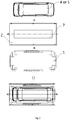
- FIG. 3 shows a combination manner of a vehicle, a carrier platform and an AGV.
- the vehicle may be the vehicle 4 to be inspected, the inspected vehicle or the vehicle 5 to be unloaded.
- a through-hole 7 may be provided on the middle of the carrier platform 2, to facilitate penetration of the radiation.
- the vehicle may be parked at the upper surface of the carrier platform 2 and fixed by a fixing means on the carrier platform 2.
- the AGV 1 can use a conventional AGV, while the lifting mechanism and the dragging mechanism may be mounted on the AGV 1, and can perform a plurality of actions such as travelling of the vehicle body, lifting of the carrier platform 2, and connection to and disengagement from the carrier platform 2 under remote control or automatic program control.
- the height of the AGV 1 may be lower than the height of the lower surface of the platform body of the carrier platform 2 so that the AGV 1 can smoothly enter and exit from the space under the carrier platform 2.
- the aforementioned vehicle inspection system is not only suitable for a smart garage or various kinds of parking garages, but also suitable for other occasions where vehicle inspection is required. For example, there is inspection when a vehicle enter and exit from some important public places (such as government departments, stadiums, theaters, etc.).
- the present disclosure further sets forth an vehicle inspection method, comprising:
- the unmanned controlled travelling device may include a vehicle body, a vertical driving mechanism and a horizontal driving mechanism, wherein the vertical driving mechanism and the horizontal driving mechanism are disposed on the vehicle body.
- the step that the unmanned controlled travelling device drives the carrier platform 2 to pass through a scanning area of the inspection device 9 may comprise that:
- the unmanned controlled travelling device carries the carrier platform 2 by moving the carrier platform 2 off the ground by means of the vertical driving mechanism.
- the vertical driving mechanism may include a lifting mechanism, such that the carrier platform 2 contains the unmanned controlled travelling device under the carrier platform 2 when the carrier platform 2 is located on the ground, and the unmanned controlled travelling device moves the carrier platform 2 off the ground by the lifting mechanism under the carrier platform 2.
- the vertical driving mechanism moves the carrier platform 2 to the ground, and the horizontal driving mechanism drives the carrier platform 2 to pass through the scanning area of the inspection device 9.
- the horizontal driving mechanism may include a dragging mechanism.
- the step that the horizontal driving mechanism drives the carrier platform 2 to pass through the scanning area of the inspection device 9 may comprises: connecting the connecting piece of the dragging mechanism with the carrier platform 2, and dragging the carrier platform 2 across the scanning area of the inspection device 9 by movement of the vehicle body.
- the unmanned controlled travelling device conveys the empty carrier platform 2 to the loading station A so that the vehicle 4 to be inspected travels on its own or is driven to the carrier platform 2.
- the embodiments of the aforementioned method may further comprise that: upon receiving a unloading instruction, the unmanned controlled travelling device moves to the parking area C of a vehicle 5 to be unloaded, and drives the carrier platform 2 carrying the vehicle 5 to be unloaded to move to the unloading station D.
Landscapes
- Engineering & Computer Science (AREA)
- Architecture (AREA)
- Civil Engineering (AREA)
- Structural Engineering (AREA)
- Mechanical Engineering (AREA)
- Aviation & Aerospace Engineering (AREA)
- Control Of Position, Course, Altitude, Or Attitude Of Moving Bodies (AREA)
- Manipulator (AREA)
- Analysing Materials By The Use Of Radiation (AREA)
Abstract
Description
- This disclosure claims the priority of the Chinese patent application No.
201611239978.9 - The present disclosure relates to the field of safety inspection, and more particularly to an vehicle inspection system and a method and a smart garage.
- With an increasingly tight use of space within a city, conventional garages occupy a large area, and are difficult to adapt to a more compact, and high-traffic occasion. In order to solve this problem, at present there has been a smart parking garage that can realize automatic parking. This smart garage often includes a multistorey, three-dimensional garage that is capable of automatically conveying a vehicle of a user to a designated parking position by intelligent control, and conveying the vehicle of the user to a designated return location when the user retrieves the vehicle.
- On the other hand, there are two common safety inspection manners of small vehicles at present: one by a driver to directly drive through a safety inspection gate, and the other by a conveyor to drag a small vehicle through a safety inspection gate. Both of these safety inspection manners are present with certain limitations. Among them, the driver driving manner involves radiation protection laws and regulations, and many countries or regions do not allow drivers to be scanned, thus affecting the applicability of such safety inspection manner. Further, the conveyor, although in diversified forms, including one-segment or two-segment, unilateral or bilateral drag, etc., may all involve civil engineering of the conveyor no matter which form is used. Such civil engineering is comparatively complicated, and the entire system presents a poor flexibility.
- With the national anti-terrorism and explosion-proof needs, there is also a safety demand for vehicles within a garage as well as the garage itself at present. However, due to their respective limitations, the aforementioned two small vehicle safety inspection manners are difficult to apply directly to the automatic parking inspection of a smart garage, so as to meet the safety requirements of the vehicles within a garage as well as the garage itself.
- The object of the present disclosure is to propose an vehicle inspection system, a method and a smart garage which can conveniently realize inspection of a vehicle and avoid scanning a driver.
- In order to realize the aforementioned object, the present disclosure provides an vehicle inspection system, comprising:
- an inspection device, for performing an inspection on a vehicle to be inspected;
- a carrier platform, for carrying the vehicle to be inspected; and
- an unmanned controlled travelling device, for moving the carrier platform to pass through a scanning area of the inspection device, so as to perform the inspection on the vehicle to be inspected.
- Further, the unmanned controlled travelling device comprises:
- a vehicle body, for travelling under remote control, and carrying the carrier platform;
- a vertical driving mechanism, provided on the vehicle body, for moving the carrier platform off the ground or placing the carrier platform on the ground; and
- a horizontal driving mechanism, provided on the vehicle body, for driving the carrier platform to pass through the scanning area of the inspection device.
- Further, the carrier platform is configured to contain the unmanned controlled travelling device under the carrier platform ; the vertical driving mechanism comprising a lifting mechanism, for moving the carrier platform off the ground when the unmanned controlled travelling device is located under the carrier platform.
- Further, the horizontal driving mechanism comprises a dragging mechanism with a connecting piece, for connecting the connecting piece with the carrier platform, and dragging the carrier platform across the scanning area of the inspection device by movement of the vehicle body.
- Further, the unmanned controlled travelling device is an Automated Guided Vehicle.
- Further, the carrier platform comprises a platform body and a support portion, the support portion is provided under the platform body, and supportable on the ground, for forming a space accommodating entry of the unmanned controlled travelling device.
- Further, a vertically penetrating through-hole is provided on the middle of the platform body, and the inspection device is a top radiation scanning inspection device, for forming a scanning area from top to bottom.
- In order to realize the aforementioned object, the present disclosure further provides a smart garage, comprising:
- the vehicle inspection system according to
claim 1, - a parking area , for parking a plurality of said carrier platforms or vehicles, the unmanned controlled travelling device for conveying the carrier platform to the parking area after accomplishing inspection of the vehicle to be inspected.
- Further, comprising a loading station and a unloading station , wherein the unmanned controlled travelling device is configured to convey the empty carrier platform to the loading station , so that the vehicle to be inspected travels on its own or is driven to the carrier platform ; the unmanned controlled travelling device is configured to move to the parking area of a vehicle to be unloaded upon receiving a loading instruction, and drive the carrier platform carrying the vehicle to be unloaded to move to the unloading station.
- In order to realize the aforementioned object, the present disclosure further provides an automatic vehicle inspection method, comprising:
- after the vehicle to be inspected is loaded on the carrier platform , the unmanned controlled travelling device moves the carrier platform to pass through a scanning area of the inspection device to perform an inspection of the vehicle to be inspected on the carrier platform;
- after inspection of the vehicle to be inspected is accomplished, the unmanned controlled travelling device drives the carrier platform to another target area.
- Further, the another target area is a designated parking area or an exit for safety inspection area corresponding to the vehicle to be inspected.
- Further, the unmanned controlled travelling device comprises a vehicle body, a vertical driving mechanism and a horizontal driving mechanism, wherein the vertical driving mechanism and the horizontal driving mechanism are disposed on the vehicle body; the step that the unmanned controlled travelling device drives the carrier platform to pass through a scanning area of the inspection device comprises:
- the unmanned controlled travelling device carries the carrier platform by moving the carrier platform off the ground by means of the vertical driving mechanism; and
- when the vehicle body moves to the vicinity of the inspection device, the vertical driving mechanism moves the carrier platform to the ground, and the horizontal driving mechanism drives the carrier platform to pass through the scanning area of the inspection device.
- Further, the horizontal driving mechanism comprises a dragging mechanism; the step that the horizontal driving mechanism drives the carrier platform to pass through the scanning area of the inspection device comprises:
- connecting the connecting piece of the dragging mechanism with the carrier platform, and dragging the carrier platform across the scanning area of the inspection device by movement of the vehicle body.
- Further, the vertical driving mechanism comprises a lifting mechanism, such that the carrier platform contains the unmanned controlled travelling device under the carrier platform when the carrier platform is located on the ground, and the unmanned controlled travelling device moves the carrier platform off the ground by the lifting mechanism under the carrier platform.
- Further, before loading the vehicle to be inspected on the carrier platform, further comprising:
- the unmanned controlled travelling device conveys the empty carrier platform to the loading station so that the vehicle to be inspected travels on its own or is driven to the carrier platform.
- Further, upon receiving a unloading instruction, the unmanned controlled travelling device moves to the parking area of a vehicle to be unloaded, and drives the carrier platform carrying the vehicle to be unloaded to move to the unloading station.
- On the basis of the aforementioned technical solution, in the present disclosure, the vehicles to be inspected is carried by the carrier platform, and the unmanned controlled walking device is used to move the carrier platform to pass through the scanning area of the inspection device, so that the vehicle to be inspected can be carried out inspection smoothly. There is no driver required to drive through the scanning area in this process, thus avoiding exposure of a driver to a threat of radiation. Moreover, as movement of the carrier platform is driven by the unmanned controlled walking device, compared to a conveyor, civil engineering construction may be omitted, while the inspection device may also be relocated at any time, thereby improving the flexibility and applicability of the automatic vehicle inspection system.
- The drawings described herein are used to provide a further understanding of the present disclosure and constitute a part of the present application. The illustrative embodiments of the present disclosure as well as the descriptions thereof, which are used for explaining the present disclosure, do not constitute improper definitions on the present disclosure. In the drawings:
-
FIG. 1 is a schematic flow chart of performing parking, inspection, and vehicle unloading of an embodiment of a smart garage according to the present disclosure. -
FIG. 2 is an enlarged schematic view of an elliptical portion inFIG. 1 . -
FIG. 3 is a schematic view of a combination manner of a vehicle, a carrier platform and an AGV in an embodiment of the vehicle inspection system of the present disclosure. - Next, the technical solution of the present disclosure is further described in detail by means of the drawings and embodiments.
- As shown in
Figure 1 , it is a schematic flow chart of performing parking, inspection, and vehicle unloading of an embodiment of a smart garage according to the present disclosure. InFIG. 1 , the smart garage first includes a parking area C that parks a plurality ofcarrier platforms 2 or vehicles, and also includes an vehicle inspection system for the vehicles which enter the garage for parking. It can be seen fromFIG. 1 that, a plurality of parking spaces located at the parking area C may include an ordinary vehicle, and may also include acarrier platform 2 that supports an ordinary vehicle. These parking spaces may be provided in such a form as to be adapted for parking an ordinary vehicle and acarrier platform 2 at the same time, and may also set their respective form suitable for parking. In another embodiment, it is also possible to only provide within a smart garage a parking area for parking thecarrier platform 2. - In this embodiment, the vehicle inspection system may specifically comprise: an
inspection device 9, acarrier platform 2 and an unmanned controlled travelling device. Among them, theinspection device 9 is used for performing inspection of avehicle 4 to be inspected, such as a non-contact inspection system and the like, which performs scanning imaging of the vehicle to be inspected by radiation, so as to identify whether the vehicle to be inspected internally carriers dangerous goods. Thecarrier platform 2 is used for carrying vehicles. It can park at the parking area and stably support the vehicles. - The unmanned controlled travelling device is responsible for driving the
carrier platform 2 through the scanning area of theinspection device 9. In other words, thecarrier platform 2 and thevehicle 4 to be inspected carried are both driven by the unmanned controlled travelling device to move, and to further accomplish such a process as to pass through the scanning area of theinspection device 9. In addition to driving thecarrier platform 2 through the scanning area of theinspection device 9, the unmanned controlled travelling device may also drive thecarrier platform 2 to move within a movement area of thecarrier platform 2. For example, after inspection of thevehicle 4 to be inspected is accomplished, thecarrier platform 2 is conveyed to the parking area C, or when it is necessary to have a vehicle unloaded, thecarrier platform 2 carrying the vehicle to be unloaded 5 is conveyed to the unloading station D. Still alternatively, when it is necessary to perform an operation of vehicle entering a garage, anempty carrier platform 2 is conveyed to the loading station A or the like. - The unmanned controlled travelling device may use an unmanned travelling device that is remotely controlled or automatically controlled. For example, an Automated Guided Vehicle AGV, its accessible range may be inside the smart garage, to effectuate entry and exit of vehicles. AGV can flexibly drive the carrier platform to move forward/backward, turn or translate, so as to realize motion of a single AGV as well as movement across of a plurality of AGVs within the accessible range.
- In the present embodiment, the vehicle to be inspected is carried by the carrier platform and the unmanned controlled travelling device is used to drive the carrier platform to pass through the scanning area of the inspection device, so that the vehicle to be inspected can be carried out inspection smoothly, thus improving the passing rate of vehicles. There is no driver required to drive through the scanning area in this process, thus avoiding a threat that the driver is exposed to radiation. Moreover, as movement of the carrier platform is driven by the unmanned controlled travelling device, compared to a conveyor, civil engineering construction may be omitted, while the inspection device may also be relocated at any time, thereby improving the flexibility and applicability of the vehicle inspection system.
- In order to facilitate that the vehicle entering the garage can be carried on the
carrier platform 2, aramp 6 may be provided at the loading station A (for example, entrance of a smart garage), so that thevehicle 4 to be inspected can reach an upper surface of thecarrier platform 2 through a top of theramp 6. This process may be accomplished by driver driving, and may also be realized by other traction tools or driving programs. In another embodiment, a depressed tunnel may also be provided at the loading station A. When thecarrier platform 2 is in the tunnel, the upper surface thereof is flush with the ground, so that thevehicle 4 to be inspected directly moves to the upper surface of thecarrier platform 2. - Similarly, in order to facilitate that the vehicle exiting from the garage can conveniently depart from the
carrier platform 2, aramp 6 may also be provided at the unloading station D (such as an outlet of the intelligent garage and the like), so that thevehicle 5 to be unloaded can leave thecarrier platform 2 from the upper surface of thecarrier platform 2 via theramp 6. This process may be accomplished by driver driving, and may also be realized by other traction tools or driving programs. In another embodiment, a depressed tunnel may also be provided at the unloading station D. When thecarrier platform 2 is in the tunnel, the upper surface thereof is flush with the ground, so that thevehicle 5 to be unloaded directly moves to the ground from the upper surface of thecarrier platform 2. - Corresponding to the unmanned controlled travelling device and the carrier platform which may respectively use different structural forms, the driving manner of the unmanned controlled travelling device for the carrier platform is also different. For example, the unmanned controlled travelling device always drives the carrier platform to move on the ground, and pass through the scanning area in a dragging manner; or the unmanned controlled travelling device drives the carrier platform to move on the ground, and pass through the scanning area in a pushing manner. Still alternatively, the unmanned controlled travelling device backs up the carrier platform to move on the ground, and pass through the scanning area in a supporting manner; or the unmanned controlled travelling device backs up the carrier platform to move on the ground in a supporting manner, and drives the carrier platform to pass through the scanning area in a dragging or pulling manner.
- Next, in combination with an enlarged view as shown in
Figure 2 , detailed description is made to an implementation process of driving thecarrier platform 2 to pass through the scanning area of theinspection device 9 by the unmanned controlled travelling device. - In the present example, the unmanned controlled travelling device has such two carrier platform driving manners as a vertically supporting carrier platform and a horizontally driving carrier platform. Thus, the unmanned controlled travelling device includes a vehicle body, a vertical driving mechanism and a horizontal driving mechanism. Among them, the vertical driving mechanism is provided on the vehicle body, for moving the
carrier platform 2 off the ground or placing thecarrier platform 2 on the ground. The horizontal driving mechanism is also provided on the vehicle body, for driving thecarrier platform 2 to pass across a scanning area of theinspection device 9. The vehicle body is used for travelling under remote control, and carrying thecarrier platform 2. Such carrying may be a direct supporting effect of the vehicle body over the lower surface of thecarrier platform 2, and may also be an indirect supporting effect of thecarrier platform 2 by means of the vertical driving mechanism. - In order to realize the vertical support of the unmanned controlled travelling device over the carrier platform, a space capable of accommodating entry of the unmanned controlled travelling device is preferably formed under the
carrier platform 2. Specifically, thecarrier platform 2 may comprise a platform body and a support portion which is provided under the platform body, is supportable on the ground, and forms a space accommodating entry of the unmanned controlled travelling device. Correspondingly, the vertical driving mechanism includes a lifting mechanism capable of moving thecarrier platform 2 off the ground when the unmanned controlled travelling device is located under thecarrier platform 2. In this way, when there is a need for the unmanned controlled travelling device to back up thecarrier platform 2 to move on the ground in a supporting manner, it is possible to first allow the unmanned controlled travelling device to enter the lower space of thecarrier platform 2, and then utilizing the lifting mechanism to uphold thecarrier platform 2 upwards, such that the unmanned controlled travelling device may drive thecarrier platform 2 and even the vehicle carried thereon to move together by means of own motion. - In order to effectuate horizontally driving the carrier platform by the unmanned controlled travelling device, it is preferable that the horizontal driving mechanism includes a dragging mechanism with a connecting piece (for example, a connecting
pin 8 inFigure 2 ), which is capable of connecting the connecting piece with thecarrier platform 2, and dragging thecarrier platform 2 across the scanning area of theinspection device 9 by movement of the vehicle body. In another implementation form, it is also possible to utilize motion of the dragging mechanism itself (for example, in a manner of a hoisting and recycling pull cord), to drag thecarrier platform 2 to pass across the scanning area of theinspection device 9. The horizontal driving mechanism may also be a pushing mechanism that imparts a pushing force to thecarrier platform 2. - In
FIG. 1 , theAGV 1 as an unmanned controlled travelling device, may support thecarrier platform 2 in advance and wait for thevehicle 4 to be inspected at the loading station A. When thevehicle 4 to be inspected reaches the upper surface of thecarrier platform 2 to perform a favorable support and fixation, theAGV 1 in a state of supporting thecarrier platform 2, carries thecarrier platform 2 and thevehicle 4 to be inspected to move to the inspection station B. Upon reaching the inspection station (e.g. one side of the inspection device 9), the lifting mechanism of theAGV 1 lowers thecarrier platform 2 until the supporting ground. At this time, theAGV 1 no longer forms a support for thecarrier platform 2 and then theAGV 1 moves out from under thecarrier platform 2, and one end of theAGV 1 is connected to one end of thecarrier platform 2 by means of the connecting pin 8 (for example, corresponding to one end at the front or rear of thevehicle 4 to be inspected). - In
FIG. 1 and FIG. 2 , the inspection process is the process that theAGV 1 drags thecarrier platform 2 and thevehicle 4 to be inspected to pass across the scanning area of theinspection device 9. Since theAGV 1 is outside the scanning area when thevehicle 4 to be inspected is scanned, theAGV 1 can shield the vehicle image as less as possible, so as not to significantly affect the scanning result of thevehicle 4 to be inspected. - The scanning area may be provided according to the structural form, principles and performance of the inspection device. Considering the circumstance that an article in the vehicle to be inspected can be more clearly inspected from the top, it is preferable to use a top radiation
scanning inspection device 9, capable of forming a scanning area from top to bottom. In order to facilitate receiving the radiation penetrating through the vehicle, it is preferable to provide a vertically penetrating through-hole 7 on the middle of the platform body (seeFIG. 3 ). - After the
vehicle 4 to be inspected is scanned, if the inspection device finds that the vehicle carries dangerous or contraband goods (such as explosives, drugs, etc.), it may refuse the vehicle to enter the smart garage, or notify the relevant department for further validation After confirming the of the vehicle after scanning, theAGV 1 re-enters under thecarrier platform 2, and raises thecarrier platform 2 by means of the lifting mechanism to leave the ground. Then, theAGV 1 conveys thecarrier platform 2 and the inspected vehicle from the inspection station B to the next target location, for example, the parking area C or the exit of the inspection area. TheAGV 1 after lowering thecarrier platform 2 and supporting the ground by means of the lifting mechanism, moves out from the space under thecarrier platform 2, and then moves to a position or a standby position of thenext carrier platform 2. - When the smart garage receives a unloading instruction, the unmanned controlled travelling device moves to the parking area C of a
vehicle 5 to be unloaded, and then drives thecarrier platform 2 carrying thevehicle 5 to be unloaded to move to the unloading station D. afterwards, thevehicle 5 to be unloaded may leave thecarrier platform 2, and be driven away from the smart garage. -
FIG. 3 shows a combination manner of a vehicle, a carrier platform and an AGV. Among them, the vehicle may be thevehicle 4 to be inspected, the inspected vehicle or thevehicle 5 to be unloaded. A through-hole 7 may be provided on the middle of thecarrier platform 2, to facilitate penetration of the radiation. The vehicle may be parked at the upper surface of thecarrier platform 2 and fixed by a fixing means on thecarrier platform 2. TheAGV 1 can use a conventional AGV, while the lifting mechanism and the dragging mechanism may be mounted on theAGV 1, and can perform a plurality of actions such as travelling of the vehicle body, lifting of thecarrier platform 2, and connection to and disengagement from thecarrier platform 2 under remote control or automatic program control. The height of theAGV 1 may be lower than the height of the lower surface of the platform body of thecarrier platform 2 so that theAGV 1 can smoothly enter and exit from the space under thecarrier platform 2. - The aforementioned vehicle inspection system is not only suitable for a smart garage or various kinds of parking garages, but also suitable for other occasions where vehicle inspection is required. For example, there is inspection when a vehicle enter and exit from some important public places (such as government departments, stadiums, theaters, etc.).
- On the basis of the aforementioned vehicle inspection system, the present disclosure further sets forth an vehicle inspection method, comprising:
- after the
vehicle 4 to be inspected is loaded on thecarrier platform 2, the unmanned controlled travelling device moves thecarrier platform 2 to pass through a scanning area of theinspection device 9, to perform an inspection of thevehicle 4 to be inspected on thecarrier platform 2; - after inspection of the
vehicle 4 to be inspected is accomplished, the unmanned controlled travelling device drives thecarrier platform 2 to another target area. Among them, the another target area may be a designated parking area or an exit for inspection area corresponding to thevehicle 4 to be inspected. - The unmanned controlled travelling device may include a vehicle body, a vertical driving mechanism and a horizontal driving mechanism, wherein the vertical driving mechanism and the horizontal driving mechanism are disposed on the vehicle body. Correspondingly, the step that the unmanned controlled travelling device drives the
carrier platform 2 to pass through a scanning area of theinspection device 9 may comprise that: - the unmanned controlled travelling device carries the
carrier platform 2 by moving thecarrier platform 2 off the ground by means of the vertical driving mechanism. The vertical driving mechanism may include a lifting mechanism, such that thecarrier platform 2 contains the unmanned controlled travelling device under thecarrier platform 2 when thecarrier platform 2 is located on the ground, and the unmanned controlled travelling device moves thecarrier platform 2 off the ground by the lifting mechanism under thecarrier platform 2. - When the vehicle body moves to the vicinity of the
inspection device 9, the vertical driving mechanism moves thecarrier platform 2 to the ground, and the horizontal driving mechanism drives thecarrier platform 2 to pass through the scanning area of theinspection device 9. The horizontal driving mechanism may include a dragging mechanism. Correspondingly, the step that the horizontal driving mechanism drives thecarrier platform 2 to pass through the scanning area of theinspection device 9 may comprises: connecting the connecting piece of the dragging mechanism with thecarrier platform 2, and dragging thecarrier platform 2 across the scanning area of theinspection device 9 by movement of the vehicle body. - In the embodiments of the aforementioned method, before the
vehicle 4 to be inspected is located on thecarrier platform 2, there may further comprise that: the unmanned controlled travelling device conveys theempty carrier platform 2 to the loading station A so that thevehicle 4 to be inspected travels on its own or is driven to thecarrier platform 2. - In addition, the embodiments of the aforementioned method may further comprise that: upon receiving a unloading instruction, the unmanned controlled travelling device moves to the parking area C of a
vehicle 5 to be unloaded, and drives thecarrier platform 2 carrying thevehicle 5 to be unloaded to move to the unloading station D. - Finally, it should be explained that: the aforementioned embodiments are only used to describe the technical solution of the present disclosure rather than limiting the same; although detailed explanations are made to the present disclosure by referring to preferred embodiments, a common technical person in the art should understand that: it is still possible to make amendments to the embodiments of the present disclosure or make equivalent replacements to part of the technical features; without departing from the spirit and scope of the present disclosure, they should all be covered in the scope of the technical solution for which protection is sought in the present disclosure.
Claims (16)
- An vehicle inspection system, comprising:an inspection device (9), for performing an inspection on a vehicle (4) to be inspected;a carrier platform (2), for carrying the vehicle (4) to be inspected; andan unmanned controlled travelling device, for moving the carrier platform (2) to pass through a scanning area of the inspection device (9), so as to perform the inspection on the vehicle (4) to be inspected.
- The vehicle inspection system according to claim 1, wherein the unmanned controlled travelling device comprises:a vehicle body, for travelling under remote control, and carrying the carrier platform (2);a vertical driving mechanism, provided on the vehicle body, for moving the carrier platform (2) off the ground or placing the carrier platform (2) on the ground; anda horizontal driving mechanism, provided on the vehicle body, for driving the carrier platform (2) to pass through the scanning area of the inspection device (9).
- The vehicle inspection system according to claim 2, wherein the carrier platform (2) is configured to contain the unmanned controlled travelling device under the carrier platform (2); the vertical driving mechanism comprising a lifting mechanism, for moving the carrier platform (2) off the ground when the unmanned controlled travelling device is located under the carrier platform (2).
- The vehicle inspection system according to claim 2, wherein the horizontal driving mechanism comprises a dragging mechanism with a connecting piece, for connecting the connecting piece with the carrier platform (2), and dragging the carrier platform (2) across the scanning area of the inspection device (9) by movement of the vehicle body.
- The container inspection system according to claim 1, wherein, the unmanned controlled travelling device is an Automated Guided Vehicle (1).
- The vehicle inspection system according to claim 1, wherein the carrier platform (2) comprises a platform body and a support portion, the support portion is provided under the platform body, and supportable on the ground, for forming a space accommodating entry of the unmanned controlled travelling device.
- The vehicle inspection system according to claim 6, wherein a vertically penetrating through-hole (7) is provided on the middle of the platform body, and the inspection device (9) is a top radiation scanning inspection device, for forming a scanning area from top to bottom.
- A smart garage, comprising:the vehicle inspection system according to claim 1,a parking area (C), for parking a plurality of said carrier platforms (2) or vehicles, the unmanned controlled travelling device for conveying the carrier platform (2) to the parking area (C) after accomplishing inspection of the vehicle to be inspected (4).
- The smart garage according to claim 8, further comprising a loading station (A) and a unloading station (D), wherein the unmanned controlled travelling device is configured to convey the empty carrier platform (2) to the loading station (A), so that the vehicle (4) to be inspected travels on its own or is driven to the carrier platform (2); the unmanned controlled travelling device is configured to move to the parking area (C) of a vehicle (5) to be unloaded upon receiving a loading instruction, and drive the carrier platform (2) carrying the vehicle (5) to be unloaded to move to the unloading station (D).
- An vehicle inspection method, comprising:after the vehicle (4) to be inspected is loaded on the carrier platform (2), the unmanned controlled travelling device moves the carrier platform (2) to pass through a scanning area of the inspection device (9) to perform an inspection of the vehicle (4) to be inspected on the carrier platform (2);after inspection of the vehicle (4) to be inspected is accomplished, the unmanned controlled travelling device drives the carrier platform (2) to another target area.
- The container inspection method according to claim 10, wherein the another target area is a designated parking area or an exit for safety inspection area corresponding to the vehicle (4) to be inspected.
- The vehicle inspection method according to claim 10, wherein the unmanned controlled travelling device comprises a vehicle body, a vertical driving mechanism and a horizontal driving mechanism, wherein the vertical driving mechanism and the horizontal driving mechanism are disposed on the vehicle body; the step that the unmanned controlled travelling device drives the carrier platform (2) to pass through a scanning area of the inspection device (9) comprises:the unmanned controlled travelling device carries the carrier platform (2) by moving the carrier platform (2) off the ground by means of the vertical driving mechanism; andwhen the vehicle body moves to the vicinity of the inspection device (9), the vertical driving mechanism moves the carrier platform (2) to the ground, and the horizontal driving mechanism drives the carrier platform (2) to pass through the scanning area of the inspection device (9).
- The vehicle inspection method according to claim 12, wherein the horizontal driving mechanism comprises a dragging mechanism; the step that the horizontal driving mechanism drives the carrier platform (2) to pass through the scanning area of the inspection device (9) comprises:connecting the connecting piece of the dragging mechanism with the carrier platform (2), and dragging the carrier platform (2) across the scanning area of the inspection device (9) by movement of the vehicle body.
- The vehicle inspection method according to claim 12, wherein the vertical driving mechanism comprises a lifting mechanism, such that the carrier platform (2) contains the unmanned controlled travelling device under the carrier platform (2) when the carrier platform (2) is located on the ground, and the unmanned controlled travelling device moves the carrier platform (2) off the ground by the lifting mechanism under the carrier platform (2).
- The vehicle inspection method according to claim 11, wherein before loading the vehicle (4) to be inspected on the carrier platform (2), further comprising:the unmanned controlled travelling device conveys the empty carrier platform (2) to the loading station (A) so that the vehicle (4) to be inspected travels on its own or is driven to the carrier platform (2).
- The vehicle inspection method according to claim 11, wherein, upon receiving a unloading instruction, the unmanned controlled travelling device moves to the parking area (C) of a vehicle (5) to be unloaded, and drives the carrier platform (2) carrying the vehicle (5) to be unloaded to move to the unloading station (D).
Priority Applications (1)
| Application Number | Priority Date | Filing Date | Title |
|---|---|---|---|
| PL17210393T PL3342960T3 (en) | 2016-12-29 | 2017-12-22 | Vehicle inspection system, method and smart garage |
Applications Claiming Priority (1)
| Application Number | Priority Date | Filing Date | Title |
|---|---|---|---|
| CN201611239978.9A CN106522628B (en) | 2016-12-29 | 2016-12-29 | Automatic vehicle inspection system and method and intelligent garage |
Publications (2)
| Publication Number | Publication Date |
|---|---|
| EP3342960A1 true EP3342960A1 (en) | 2018-07-04 |
| EP3342960B1 EP3342960B1 (en) | 2019-10-02 |
Family
ID=58339098
Family Applications (1)
| Application Number | Title | Priority Date | Filing Date |
|---|---|---|---|
| EP17210393.9A Active EP3342960B1 (en) | 2016-12-29 | 2017-12-22 | Vehicle inspection system, method and smart garage |
Country Status (6)
| Country | Link |
|---|---|
| US (1) | US10718128B2 (en) |
| EP (1) | EP3342960B1 (en) |
| CN (1) | CN106522628B (en) |
| BR (1) | BR102017028407B1 (en) |
| MY (1) | MY188731A (en) |
| PL (1) | PL3342960T3 (en) |
Cited By (2)
| Publication number | Priority date | Publication date | Assignee | Title |
|---|---|---|---|---|
| RU2712891C1 (en) * | 2019-04-01 | 2020-01-31 | Михаил Наркисович Виноградов | Mechanized modular garage |
| CN113108218A (en) * | 2021-04-09 | 2021-07-13 | 盛视科技股份有限公司 | Mobile vehicle chassis checking device, system and method |
Families Citing this family (7)
| Publication number | Priority date | Publication date | Assignee | Title |
|---|---|---|---|---|
| CN106921195A (en) * | 2017-04-11 | 2017-07-04 | 北京华力兴科技发展有限责任公司 | Vehicle inspection system based on AGV |
| CN109214483B (en) * | 2018-09-13 | 2021-11-02 | 公安部道路交通安全研究中心 | Motor vehicle inspection system and method |
| CN111942825A (en) * | 2018-10-16 | 2020-11-17 | 宋海燕 | Transmission device with security check function for inlet and outlet |
| CN110282384A (en) * | 2019-06-27 | 2019-09-27 | 北京埃索特核电子机械有限公司 | A kind of passenger car based on vehicle conveying robot fast and safely checks system |
| CN113744517B (en) * | 2020-05-29 | 2022-09-27 | 同方威视技术股份有限公司 | Vehicle inspection system and method therefor |
| CN113820139B (en) * | 2020-06-18 | 2022-12-06 | 同方威视技术股份有限公司 | Automatic guidance system and method and vehicle inspection system |
| CN114764073B (en) * | 2020-12-31 | 2024-03-15 | 同方威视科技(北京)有限公司 | Vehicle radiation inspection equipment and vehicle radiation inspection system |
Citations (3)
| Publication number | Priority date | Publication date | Assignee | Title |
|---|---|---|---|---|
| DE29803989U1 (en) * | 1998-03-06 | 1998-12-17 | Siemens AG, 80333 München | Entry and exit terminal for parking garages or other vehicle storage |
| US6542580B1 (en) * | 2002-01-15 | 2003-04-01 | Rapiscan Security Products (Usa), Inc. | Relocatable X-ray imaging system and method for inspecting vehicles and containers |
| JP2014153099A (en) * | 2013-02-06 | 2014-08-25 | Ihi Inspection & Instrumentation Co Ltd | Conveyance device of vehicle for x ray inspection |
Family Cites Families (5)
| Publication number | Priority date | Publication date | Assignee | Title |
|---|---|---|---|---|
| US20070040911A1 (en) * | 2005-01-31 | 2007-02-22 | Riley Larry E | Under vehicle inspection system |
| US8583313B2 (en) * | 2008-09-19 | 2013-11-12 | International Electronic Machines Corp. | Robotic vehicle for performing rail-related actions |
| CN203808582U (en) * | 2013-07-01 | 2014-09-03 | 梁崇彦 | Vehicle ultra-width detection devices of mechanical parking equipment |
| CN103556856B (en) * | 2013-10-31 | 2016-08-17 | 深圳怡丰自动化科技有限公司 | Mechanical stereo garage goes out to put in storage room platform |
| CN206468073U (en) * | 2016-12-29 | 2017-09-05 | 同方威视技术股份有限公司 | Automotive vehicle inspection system and intelligent garage |
-
2016
- 2016-12-29 CN CN201611239978.9A patent/CN106522628B/en active Active
-
2017
- 2017-12-22 MY MYPI2017705000A patent/MY188731A/en unknown
- 2017-12-22 EP EP17210393.9A patent/EP3342960B1/en active Active
- 2017-12-22 PL PL17210393T patent/PL3342960T3/en unknown
- 2017-12-28 BR BR102017028407-7A patent/BR102017028407B1/en active IP Right Grant
- 2017-12-29 US US15/857,645 patent/US10718128B2/en active Active
Patent Citations (3)
| Publication number | Priority date | Publication date | Assignee | Title |
|---|---|---|---|---|
| DE29803989U1 (en) * | 1998-03-06 | 1998-12-17 | Siemens AG, 80333 München | Entry and exit terminal for parking garages or other vehicle storage |
| US6542580B1 (en) * | 2002-01-15 | 2003-04-01 | Rapiscan Security Products (Usa), Inc. | Relocatable X-ray imaging system and method for inspecting vehicles and containers |
| JP2014153099A (en) * | 2013-02-06 | 2014-08-25 | Ihi Inspection & Instrumentation Co Ltd | Conveyance device of vehicle for x ray inspection |
Cited By (2)
| Publication number | Priority date | Publication date | Assignee | Title |
|---|---|---|---|---|
| RU2712891C1 (en) * | 2019-04-01 | 2020-01-31 | Михаил Наркисович Виноградов | Mechanized modular garage |
| CN113108218A (en) * | 2021-04-09 | 2021-07-13 | 盛视科技股份有限公司 | Mobile vehicle chassis checking device, system and method |
Also Published As
| Publication number | Publication date |
|---|---|
| US20180187443A1 (en) | 2018-07-05 |
| MY188731A (en) | 2021-12-27 |
| EP3342960B1 (en) | 2019-10-02 |
| PL3342960T3 (en) | 2020-04-30 |
| BR102017028407A2 (en) | 2018-12-04 |
| BR102017028407B1 (en) | 2022-11-29 |
| CN106522628A (en) | 2017-03-22 |
| US10718128B2 (en) | 2020-07-21 |
| CN106522628B (en) | 2022-03-04 |
Similar Documents
| Publication | Publication Date | Title |
|---|---|---|
| EP3342960B1 (en) | Vehicle inspection system, method and smart garage | |
| US9140028B2 (en) | Automated parking system | |
| JP6538891B2 (en) | Concept for transferring a vehicle from the start position to the target position | |
| CN106290419A (en) | Removable split type inspection system and method | |
| JP2002321699A (en) | Air freight transport system | |
| US20170167154A1 (en) | Automated vehicle parking system | |
| JP7004248B2 (en) | Coupling device, connecting mobile device and autonomous mobile device | |
| JP7296199B2 (en) | Automatic parking assistance system for mechanical parking equipment | |
| JP2015168985A (en) | mechanical parking equipment | |
| CN206468073U (en) | Automotive vehicle inspection system and intelligent garage | |
| KR20190092747A (en) | A guide system and guide method for parking lot | |
| WO2020235320A1 (en) | Foreign body detection system and method | |
| US12077413B2 (en) | Transportation system | |
| CN114764073B (en) | Vehicle radiation inspection equipment and vehicle radiation inspection system | |
| CN206074483U (en) | May move split type inspection system | |
| MXPA06013288A (en) | Vehicle storage system . | |
| KR20180065320A (en) | Loading and unloading apparatus for luggage of vehicle | |
| JP6964984B2 (en) | Mechanical parking lot | |
| CN206448580U (en) | A kind of intelligent parking garage gateway platform and intelligent parking garage | |
| JP7685637B2 (en) | Storage entry support method and storage entry support device | |
| JP6799897B2 (en) | Unmanned confirmation system for three-dimensional parking device, three-dimensional parking device equipped with this, and unmanned confirmation method for three-dimensional parking device | |
| TWI600990B (en) | Method of controlling unmanned material transportation vehicle | |
| HK40080965A (en) | Transportation system | |
| JP2015224440A (en) | Parking lot equipment | |
| HK40080965B (en) | Transportation system |
Legal Events
| Date | Code | Title | Description |
|---|---|---|---|
| PUAI | Public reference made under article 153(3) epc to a published international application that has entered the european phase |
Free format text: ORIGINAL CODE: 0009012 |
|
| STAA | Information on the status of an ep patent application or granted ep patent |
Free format text: STATUS: REQUEST FOR EXAMINATION WAS MADE |
|
| 17P | Request for examination filed |
Effective date: 20171222 |
|
| AK | Designated contracting states |
Kind code of ref document: A1 Designated state(s): AL AT BE BG CH CY CZ DE DK EE ES FI FR GB GR HR HU IE IS IT LI LT LU LV MC MK MT NL NO PL PT RO RS SE SI SK SM TR |
|
| AX | Request for extension of the european patent |
Extension state: BA ME |
|
| RBV | Designated contracting states (corrected) |
Designated state(s): AL AT BE BG CH CY CZ DE DK EE ES FI FR GB GR HR HU IE IS IT LI LT LU LV MC MK MT NL NO PL PT RO RS SE SI SK SM TR |
|
| GRAP | Despatch of communication of intention to grant a patent |
Free format text: ORIGINAL CODE: EPIDOSNIGR1 |
|
| STAA | Information on the status of an ep patent application or granted ep patent |
Free format text: STATUS: GRANT OF PATENT IS INTENDED |
|
| INTG | Intention to grant announced |
Effective date: 20190416 |
|
| GRAS | Grant fee paid |
Free format text: ORIGINAL CODE: EPIDOSNIGR3 |
|
| GRAA | (expected) grant |
Free format text: ORIGINAL CODE: 0009210 |
|
| STAA | Information on the status of an ep patent application or granted ep patent |
Free format text: STATUS: THE PATENT HAS BEEN GRANTED |
|
| AK | Designated contracting states |
Kind code of ref document: B1 Designated state(s): AL AT BE BG CH CY CZ DE DK EE ES FI FR GB GR HR HU IE IS IT LI LT LU LV MC MK MT NL NO PL PT RO RS SE SI SK SM TR |
|
| REG | Reference to a national code |
Ref country code: GB Ref legal event code: FG4D |
|
| REG | Reference to a national code |
Ref country code: CH Ref legal event code: EP Ref country code: AT Ref legal event code: REF Ref document number: 1186335 Country of ref document: AT Kind code of ref document: T Effective date: 20191015 |
|
| REG | Reference to a national code |
Ref country code: DE Ref legal event code: R096 Ref document number: 602017007477 Country of ref document: DE |
|
| REG | Reference to a national code |
Ref country code: IE Ref legal event code: FG4D |
|
| REG | Reference to a national code |
Ref country code: NL Ref legal event code: FP |
|
| REG | Reference to a national code |
Ref country code: LT Ref legal event code: MG4D |
|
| REG | Reference to a national code |
Ref country code: AT Ref legal event code: MK05 Ref document number: 1186335 Country of ref document: AT Kind code of ref document: T Effective date: 20191002 |
|
| PG25 | Lapsed in a contracting state [announced via postgrant information from national office to epo] |
Ref country code: AT Free format text: LAPSE BECAUSE OF FAILURE TO SUBMIT A TRANSLATION OF THE DESCRIPTION OR TO PAY THE FEE WITHIN THE PRESCRIBED TIME-LIMIT Effective date: 20191002 Ref country code: LT Free format text: LAPSE BECAUSE OF FAILURE TO SUBMIT A TRANSLATION OF THE DESCRIPTION OR TO PAY THE FEE WITHIN THE PRESCRIBED TIME-LIMIT Effective date: 20191002 Ref country code: GR Free format text: LAPSE BECAUSE OF FAILURE TO SUBMIT A TRANSLATION OF THE DESCRIPTION OR TO PAY THE FEE WITHIN THE PRESCRIBED TIME-LIMIT Effective date: 20200103 Ref country code: FI Free format text: LAPSE BECAUSE OF FAILURE TO SUBMIT A TRANSLATION OF THE DESCRIPTION OR TO PAY THE FEE WITHIN THE PRESCRIBED TIME-LIMIT Effective date: 20191002 Ref country code: BG Free format text: LAPSE BECAUSE OF FAILURE TO SUBMIT A TRANSLATION OF THE DESCRIPTION OR TO PAY THE FEE WITHIN THE PRESCRIBED TIME-LIMIT Effective date: 20200102 Ref country code: NO Free format text: LAPSE BECAUSE OF FAILURE TO SUBMIT A TRANSLATION OF THE DESCRIPTION OR TO PAY THE FEE WITHIN THE PRESCRIBED TIME-LIMIT Effective date: 20200102 Ref country code: SE Free format text: LAPSE BECAUSE OF FAILURE TO SUBMIT A TRANSLATION OF THE DESCRIPTION OR TO PAY THE FEE WITHIN THE PRESCRIBED TIME-LIMIT Effective date: 20191002 Ref country code: LV Free format text: LAPSE BECAUSE OF FAILURE TO SUBMIT A TRANSLATION OF THE DESCRIPTION OR TO PAY THE FEE WITHIN THE PRESCRIBED TIME-LIMIT Effective date: 20191002 Ref country code: PT Free format text: LAPSE BECAUSE OF FAILURE TO SUBMIT A TRANSLATION OF THE DESCRIPTION OR TO PAY THE FEE WITHIN THE PRESCRIBED TIME-LIMIT Effective date: 20200203 |
|
| PG25 | Lapsed in a contracting state [announced via postgrant information from national office to epo] |
Ref country code: IS Free format text: LAPSE BECAUSE OF FAILURE TO SUBMIT A TRANSLATION OF THE DESCRIPTION OR TO PAY THE FEE WITHIN THE PRESCRIBED TIME-LIMIT Effective date: 20200224 Ref country code: HR Free format text: LAPSE BECAUSE OF FAILURE TO SUBMIT A TRANSLATION OF THE DESCRIPTION OR TO PAY THE FEE WITHIN THE PRESCRIBED TIME-LIMIT Effective date: 20191002 Ref country code: CZ Free format text: LAPSE BECAUSE OF FAILURE TO SUBMIT A TRANSLATION OF THE DESCRIPTION OR TO PAY THE FEE WITHIN THE PRESCRIBED TIME-LIMIT Effective date: 20191002 Ref country code: RS Free format text: LAPSE BECAUSE OF FAILURE TO SUBMIT A TRANSLATION OF THE DESCRIPTION OR TO PAY THE FEE WITHIN THE PRESCRIBED TIME-LIMIT Effective date: 20191002 |
|
| PG25 | Lapsed in a contracting state [announced via postgrant information from national office to epo] |
Ref country code: AL Free format text: LAPSE BECAUSE OF FAILURE TO SUBMIT A TRANSLATION OF THE DESCRIPTION OR TO PAY THE FEE WITHIN THE PRESCRIBED TIME-LIMIT Effective date: 20191002 |
|
| REG | Reference to a national code |
Ref country code: DE Ref legal event code: R097 Ref document number: 602017007477 Country of ref document: DE |
|
| PG2D | Information on lapse in contracting state deleted |
Ref country code: IS |
|
| PG25 | Lapsed in a contracting state [announced via postgrant information from national office to epo] |
Ref country code: RO Free format text: LAPSE BECAUSE OF FAILURE TO SUBMIT A TRANSLATION OF THE DESCRIPTION OR TO PAY THE FEE WITHIN THE PRESCRIBED TIME-LIMIT Effective date: 20191002 Ref country code: EE Free format text: LAPSE BECAUSE OF FAILURE TO SUBMIT A TRANSLATION OF THE DESCRIPTION OR TO PAY THE FEE WITHIN THE PRESCRIBED TIME-LIMIT Effective date: 20191002 Ref country code: DK Free format text: LAPSE BECAUSE OF FAILURE TO SUBMIT A TRANSLATION OF THE DESCRIPTION OR TO PAY THE FEE WITHIN THE PRESCRIBED TIME-LIMIT Effective date: 20191002 Ref country code: IS Free format text: LAPSE BECAUSE OF FAILURE TO SUBMIT A TRANSLATION OF THE DESCRIPTION OR TO PAY THE FEE WITHIN THE PRESCRIBED TIME-LIMIT Effective date: 20200202 |
|
| PLBE | No opposition filed within time limit |
Free format text: ORIGINAL CODE: 0009261 |
|
| STAA | Information on the status of an ep patent application or granted ep patent |
Free format text: STATUS: NO OPPOSITION FILED WITHIN TIME LIMIT |
|
| REG | Reference to a national code |
Ref country code: BE Ref legal event code: MM Effective date: 20191231 |
|
| PG25 | Lapsed in a contracting state [announced via postgrant information from national office to epo] |
Ref country code: SM Free format text: LAPSE BECAUSE OF FAILURE TO SUBMIT A TRANSLATION OF THE DESCRIPTION OR TO PAY THE FEE WITHIN THE PRESCRIBED TIME-LIMIT Effective date: 20191002 Ref country code: IT Free format text: LAPSE BECAUSE OF FAILURE TO SUBMIT A TRANSLATION OF THE DESCRIPTION OR TO PAY THE FEE WITHIN THE PRESCRIBED TIME-LIMIT Effective date: 20191002 Ref country code: MC Free format text: LAPSE BECAUSE OF FAILURE TO SUBMIT A TRANSLATION OF THE DESCRIPTION OR TO PAY THE FEE WITHIN THE PRESCRIBED TIME-LIMIT Effective date: 20191002 Ref country code: SK Free format text: LAPSE BECAUSE OF FAILURE TO SUBMIT A TRANSLATION OF THE DESCRIPTION OR TO PAY THE FEE WITHIN THE PRESCRIBED TIME-LIMIT Effective date: 20191002 |
|
| 26N | No opposition filed |
Effective date: 20200703 |
|
| PG25 | Lapsed in a contracting state [announced via postgrant information from national office to epo] |
Ref country code: IE Free format text: LAPSE BECAUSE OF NON-PAYMENT OF DUE FEES Effective date: 20191222 Ref country code: LU Free format text: LAPSE BECAUSE OF NON-PAYMENT OF DUE FEES Effective date: 20191222 Ref country code: ES Free format text: LAPSE BECAUSE OF FAILURE TO SUBMIT A TRANSLATION OF THE DESCRIPTION OR TO PAY THE FEE WITHIN THE PRESCRIBED TIME-LIMIT Effective date: 20191002 |
|
| PG25 | Lapsed in a contracting state [announced via postgrant information from national office to epo] |
Ref country code: BE Free format text: LAPSE BECAUSE OF NON-PAYMENT OF DUE FEES Effective date: 20191231 Ref country code: SI Free format text: LAPSE BECAUSE OF FAILURE TO SUBMIT A TRANSLATION OF THE DESCRIPTION OR TO PAY THE FEE WITHIN THE PRESCRIBED TIME-LIMIT Effective date: 20191002 |
|
| PG25 | Lapsed in a contracting state [announced via postgrant information from national office to epo] |
Ref country code: CY Free format text: LAPSE BECAUSE OF FAILURE TO SUBMIT A TRANSLATION OF THE DESCRIPTION OR TO PAY THE FEE WITHIN THE PRESCRIBED TIME-LIMIT Effective date: 20191002 |
|
| PG25 | Lapsed in a contracting state [announced via postgrant information from national office to epo] |
Ref country code: MT Free format text: LAPSE BECAUSE OF FAILURE TO SUBMIT A TRANSLATION OF THE DESCRIPTION OR TO PAY THE FEE WITHIN THE PRESCRIBED TIME-LIMIT Effective date: 20191002 Ref country code: HU Free format text: LAPSE BECAUSE OF FAILURE TO SUBMIT A TRANSLATION OF THE DESCRIPTION OR TO PAY THE FEE WITHIN THE PRESCRIBED TIME-LIMIT; INVALID AB INITIO Effective date: 20171222 |
|
| REG | Reference to a national code |
Ref country code: CH Ref legal event code: PL |
|
| PG25 | Lapsed in a contracting state [announced via postgrant information from national office to epo] |
Ref country code: CH Free format text: LAPSE BECAUSE OF NON-PAYMENT OF DUE FEES Effective date: 20201231 Ref country code: LI Free format text: LAPSE BECAUSE OF NON-PAYMENT OF DUE FEES Effective date: 20201231 |
|
| PG25 | Lapsed in a contracting state [announced via postgrant information from national office to epo] |
Ref country code: TR Free format text: LAPSE BECAUSE OF FAILURE TO SUBMIT A TRANSLATION OF THE DESCRIPTION OR TO PAY THE FEE WITHIN THE PRESCRIBED TIME-LIMIT Effective date: 20191002 |
|
| PG25 | Lapsed in a contracting state [announced via postgrant information from national office to epo] |
Ref country code: MK Free format text: LAPSE BECAUSE OF FAILURE TO SUBMIT A TRANSLATION OF THE DESCRIPTION OR TO PAY THE FEE WITHIN THE PRESCRIBED TIME-LIMIT Effective date: 20191002 |
|
| P01 | Opt-out of the competence of the unified patent court (upc) registered |
Effective date: 20230528 |
|
| PGFP | Annual fee paid to national office [announced via postgrant information from national office to epo] |
Ref country code: DE Payment date: 20241216 Year of fee payment: 8 |
|
| PGFP | Annual fee paid to national office [announced via postgrant information from national office to epo] |
Ref country code: NL Payment date: 20241217 Year of fee payment: 8 Ref country code: PL Payment date: 20241211 Year of fee payment: 8 |
|
| PGFP | Annual fee paid to national office [announced via postgrant information from national office to epo] |
Ref country code: GB Payment date: 20241017 Year of fee payment: 8 |
|
| PGFP | Annual fee paid to national office [announced via postgrant information from national office to epo] |
Ref country code: FR Payment date: 20241108 Year of fee payment: 8 |
|
| REG | Reference to a national code |
Ref country code: NL Ref legal event code: MM Effective date: 20260101 |