EP3341680B1 - Braking system - Google Patents
Braking system Download PDFInfo
- Publication number
- EP3341680B1 EP3341680B1 EP16759847.3A EP16759847A EP3341680B1 EP 3341680 B1 EP3341680 B1 EP 3341680B1 EP 16759847 A EP16759847 A EP 16759847A EP 3341680 B1 EP3341680 B1 EP 3341680B1
- Authority
- EP
- European Patent Office
- Prior art keywords
- braking
- operative
- braking system
- magnet
- brake
- Prior art date
- Legal status (The legal status is an assumption and is not a legal conclusion. Google has not performed a legal analysis and makes no representation as to the accuracy of the status listed.)
- Active
Links
- 230000001052 transient effect Effects 0.000 claims description 27
- 230000007246 mechanism Effects 0.000 claims description 16
- 239000003990 capacitor Substances 0.000 claims description 11
- 238000004146 energy storage Methods 0.000 claims description 4
- 230000033001 locomotion Effects 0.000 description 26
- 239000000523 sample Substances 0.000 description 12
- 230000004907 flux Effects 0.000 description 9
- 238000004519 manufacturing process Methods 0.000 description 6
- 230000004913 activation Effects 0.000 description 5
- 238000009434 installation Methods 0.000 description 4
- 230000008901 benefit Effects 0.000 description 3
- 230000000052 comparative effect Effects 0.000 description 3
- 238000010586 diagram Methods 0.000 description 3
- 239000000696 magnetic material Substances 0.000 description 3
- 229910000831 Steel Inorganic materials 0.000 description 2
- 230000002411 adverse Effects 0.000 description 2
- 229910000828 alnico Inorganic materials 0.000 description 2
- 230000006378 damage Effects 0.000 description 2
- 230000005484 gravity Effects 0.000 description 2
- 239000000463 material Substances 0.000 description 2
- 238000005259 measurement Methods 0.000 description 2
- 239000010959 steel Substances 0.000 description 2
- 241000238631 Hexapoda Species 0.000 description 1
- 229910052779 Neodymium Inorganic materials 0.000 description 1
- 208000027418 Wounds and injury Diseases 0.000 description 1
- 229910045601 alloy Inorganic materials 0.000 description 1
- 239000000956 alloy Substances 0.000 description 1
- 230000001276 controlling effect Effects 0.000 description 1
- 230000003247 decreasing effect Effects 0.000 description 1
- 238000006073 displacement reaction Methods 0.000 description 1
- 230000000694 effects Effects 0.000 description 1
- 238000002474 experimental method Methods 0.000 description 1
- 208000014674 injury Diseases 0.000 description 1
- 238000007689 inspection Methods 0.000 description 1
- 238000012544 monitoring process Methods 0.000 description 1
- QEFYFXOXNSNQGX-UHFFFAOYSA-N neodymium atom Chemical compound [Nd] QEFYFXOXNSNQGX-UHFFFAOYSA-N 0.000 description 1
- 229910001172 neodymium magnet Inorganic materials 0.000 description 1
- 230000009467 reduction Effects 0.000 description 1
- 230000001105 regulatory effect Effects 0.000 description 1
- 230000009495 transient activation Effects 0.000 description 1
Images


Classifications
-
- G—PHYSICS
- G01—MEASURING; TESTING
- G01B—MEASURING LENGTH, THICKNESS OR SIMILAR LINEAR DIMENSIONS; MEASURING ANGLES; MEASURING AREAS; MEASURING IRREGULARITIES OF SURFACES OR CONTOURS
- G01B21/00—Measuring arrangements or details thereof, where the measuring technique is not covered by the other groups of this subclass, unspecified or not relevant
- G01B21/02—Measuring arrangements or details thereof, where the measuring technique is not covered by the other groups of this subclass, unspecified or not relevant for measuring length, width, or thickness
- G01B21/04—Measuring arrangements or details thereof, where the measuring technique is not covered by the other groups of this subclass, unspecified or not relevant for measuring length, width, or thickness by measuring coordinates of points
- G01B21/047—Accessories, e.g. for positioning, for tool-setting, for measuring probes
-
- F—MECHANICAL ENGINEERING; LIGHTING; HEATING; WEAPONS; BLASTING
- F16—ENGINEERING ELEMENTS AND UNITS; GENERAL MEASURES FOR PRODUCING AND MAINTAINING EFFECTIVE FUNCTIONING OF MACHINES OR INSTALLATIONS; THERMAL INSULATION IN GENERAL
- F16D—COUPLINGS FOR TRANSMITTING ROTATION; CLUTCHES; BRAKES
- F16D2121/00—Type of actuator operation force
- F16D2121/18—Electric or magnetic
- F16D2121/20—Electric or magnetic using electromagnets
-
- F—MECHANICAL ENGINEERING; LIGHTING; HEATING; WEAPONS; BLASTING
- F16—ENGINEERING ELEMENTS AND UNITS; GENERAL MEASURES FOR PRODUCING AND MAINTAINING EFFECTIVE FUNCTIONING OF MACHINES OR INSTALLATIONS; THERMAL INSULATION IN GENERAL
- F16D—COUPLINGS FOR TRANSMITTING ROTATION; CLUTCHES; BRAKES
- F16D65/00—Parts or details
- F16D65/14—Actuating mechanisms for brakes; Means for initiating operation at a predetermined position
Definitions
- This invention relates to braking systems.
- a position determining apparatus e.g. for dimensional metrology.
- a position determining apparatus may comprise a movable member for holding a probe or other tool, which is movable in one, two or three dimensions relative to a fixed member or base in order to perform measurement or other operations on a workpiece.
- the movement may be driven by a motor or motors, or manually.
- position determining apparatus examples include coordinate measuring machines (CMM), comparative gauging machines, machine tools, manual coordinate measuring arms and robots.
- CMM coordinate measuring machines
- the apparatus may be a so-called Cartesian machine, in which the movable member supporting the probe or other tool is mounted via three serially-connected carriages which are respectively movable in three orthogonal directions X,Y,Z. This is an example of a "serial kinematic" motion system.
- the measuring apparatus may be a non-Cartesian machine, for example having a "parallel kinematic" motion system comprising three or six extensible struts which are each connected in parallel between the movable member and the relatively fixed member or base.
- the motion of the movable member (and thus the probe or tool) in the X,Y,Z working volume is then controlled by coordinating the respective extensions of the three or six struts.
- An example of a non-Cartesian machine is shown in International Patent Applications WO 03/006837 and WO 2004/063579 .
- Such apparatus may be provided with a braking system to prevent motion of the movable member when not in use. For example, this may prevent it sinking under gravity. In some circumstances it may also be important to apply the braking system to arrest the motion in a fail-safe manner, for example in the event of a power failure. This may prevent the movable member (or its probe or tool) crashing into something or someone, possibly causing damage or injury.
- Braking systems for other types of apparatus in which a biasing force is applied to a braking element by a passive element such as a permanent magnet or a spring, to bias the braking element into an operative braking position.
- a passive element such as a permanent magnet or a spring
- an active element such as an electromagnetic coil is energised, counteracting the biasing force of the passive element.
- DE 3434116 A1 discloses an electromagnetic brake having a permanent magnet and electromagnet in combination with a spring, with a current pulse through the electromagnet causing the brake to be applied or released.
- DE 19752543 A1 discloses a similar type of arrangement.
- EP 1801535 A2 discloses an electromagnetic brake having a permanent magnet which is moved between two positions by operation of an electromagnet, thereby applying or releasing the brake.
- the present invention provides a braking system according to claim 1 for braking a movable member, comprising:
- this avoids or reduces the need for continuous energisation to hold the braking element in the inoperative position during normal movement of the movable member.
- Possible advantages which result may include a limitation of thermal growth and/or increased energy efficiency.
- the electrically-operated device may be electro-magnetic, in which case its electro-magnetic force may be arranged to act on the braking element to switch it between the operative and inoperative positions. And/or the electrically-operated device may be coupled to the braking element mechanically.
- the braking device comprises an energy storage device (such as a capacitor) configured to supply the transient pulse to one or more of the active elements in the event of a power supply failure, to switch the braking element from the inoperative position to the operative braking position.
- an energy storage device such as a capacitor
- the energy storage device may be a capacitor.
- the one or more active elements are not energised. However, they may be energised by a current which is less than the transient pulse of electrical current.
- the one or more active elements may include an electromagnetic coil associated with the soft permanent magnet.
- the one or more passive elements may include a spring.
- the electro-magnetic device may be bistable or may include a bistable mechanism, whereby it is stable in both the operative and inoperative braking positions.
- Fig 1 is an illustration of parts of a coordinate measuring apparatus.
- the apparatus is a comparative gauging machine 10 as sold by the present applicants Renishaw plc under the trademark EQUATOR. It comprises a fixed platform 30 connected to a movable platform 32 by a non-Cartesian parallel kinematic motion system.
- the parallel kinematic motion system comprises three struts 34 which act in parallel between the fixed and movable platforms.
- the three struts 34 pass through three respective actuators 36, by which they can be extended and retracted.
- One end of each strut 34 is mounted by a universally pivotable joint to the movable platform 32, and the actuators 36 are likewise universally pivotably mounted to the fixed platform 30.
- the actuators 36 each comprise a motor for extending and retracting the respective strut, and a transducer which measures the extension of the respective strut 34.
- the transducer may be an encoder comprising a scale and readhead, with a counter for the output of the readhead.
- Each motor and transducer forms part of a respective servo loop controlled by a controller or computer 8.
- the motor may act through any suitable mechanism to extend and retract the strut, such as a rack and pinion.
- One preferred mechanism is a low-hysteresis drive with a toothed belt wrapped around a pinion on the motor spindle, for example in an ⁇ -shape maintained by an idler wheel or wheels.
- the parallel kinematic motion system also comprises three passive anti-rotation devices 38, 39 which also act in parallel between the fixed and movable platforms.
- Each anti-rotation device comprises a rigid plate 39 hinged to the fixed platform 30 and a parallel, spaced pair of rods 38 which are universally pivotably connected between the rigid plate 39 and the movable platform 32.
- the anti-rotation devices cooperate to constrain the movable platform 32 against movement in all three rotational degrees of freedom. Therefore, the movable platform 32 is constrained to move only with three translational degrees of freedom X, Y, Z.
- the controller/computer 8 can produce any desired X, Y, Z displacement or X, Y, Z positioning of the movable platform.
- the transducers of the three actuators form a position measuring system. This determines the X, Y, Z position of the movable platform 32 relative to the fixed platform 30, by appropriate calculations in the controller or computer 8. These calculations are known to the skilled person.
- an analogue probe 16 having a deflectable stylus 20 with a workpiece contacting tip 22 is mounted on the movable platform 32 of the machine, although other types of probes (including touch trigger probes) may be used.
- the machine moves the probe 16 relative to a workpiece 14 on a table 12 in order to carry out measurements of features of the workpiece.
- the X, Y, Z position of a point on the workpiece surface is derived by calculation from the transducers in the servo system, in conjunction with the outputs of the analogue probe 16. This is all controlled by the controller/computer 8.
- a signal indicating that the probe has contacted the surface of the workpiece freezes the X,Y,Z position value calculated from the output from the transducers and the computer takes a reading of the coordinates of the workpiece surface.
- automatic means such as a robot (not shown) may place each of a succession of substantially identical workpieces from a production run in at least nominally the same position and orientation on the table.
- the parallel kinematic measuring apparatus of Fig 1 is only one example of a type of apparatus in which the present invention can be used.
- Other examples include measuring apparatus with serial kinematic motion systems, such as a conventional Cartesian CMM with three serially-connected carriages which are movable orthogonally in XYZ directions. This could be computer controlled or manually operated.
- Another possible serial kinematic machine is an inspection robot or a manual articulating arm, with multiple articulating arm members connected serially by multiple rotary joints.
- the invention is also applicable to systems with linear motion in only one or two directions, and/or rotary motion about one or more axes.
- Whichever type of machine is used, typically it is placed in a workshop environment in order to inspect production workpieces from an automated manufacturing process.
- Figs 2 and 3 show a braking system which is included within each of the actuators 36.
- the motor in the actuator has a rotor 42 mounted for rotation in a housing 40.
- a planar spring 46 is mounted on the end of the housing 40, and an annular brake pad 44 is mounted on one side of the planar spring, facing the rotor.
- the planar spring 46 has spiral cut-outs 48 so that the spring allows the brake pad to move axially towards and away from the rotor. In its normal relaxed state with no other forces acting, the planar spring 46 acts as a passive element which holds the brake pad 44 off the rotor 42, so that the motor is free to rotate, extending and retracting the strut 34.
- An electropermanent magnet assembly 50 is mounted on the other side of the planar spring, opposite the rotor. It has two end plates 52, which extend through the planar spring to form a magnetic circuit with the rotor 42. When the electropermanent magnet applies a magnetic force as described below, the end plates are pulled axially towards the rotor, deflecting the planar spring, and causing the brake pad 44 to engage frictionally with the rotor 42, applying a braking force.
- the electropermanent magnet assembly 50 comprises a hard (permanent) magnet 54 and a soft (semi-permanent) magnet 56, arranged side-by-side in a parallel arrangement. They are surrounded by an electromagnetic coil 58, which forms an active element.
- arrows indicate the magnetic polarities of the hard and soft magnets 54, 56.
- the hard magnet 54 may be made from a material such as sintered neodymium.
- the soft (semi-permanent) magnet 56 may be made of a material such as an AlNiCo alloy, with a coercivity chosen such that its magnetic polarity can be switched back and forth from one direction to the other by the application of a transient switching pulse (or activation pulse) of current through the coil 58. Its magnetic polarity then remains in the reversed state with no applied current, until the application of another transient switching pulse of current in the opposite sense switches it back again. Meanwhile, the magnetic polarity of the hard magnet 54 is unaffected by these current pulses.
- Figs 4 and 5 show the two possible resulting bistable states of the electropermanent magnet assembly 50.
- Fig 4 the polarities of the magnets 54, 56 are in a state of alignment and their magnetic forces reinforce each other.
- a magnetic circuit is formed through the end plates 52 and the rotor 42, pulling the brake pad 44 into frictional engagement with the rotor.
- the magnets 54, 56 then act as passive elements to apply the brake to prevent motion of the strut 34.
- the electromagnetic coil 58 could be wrapped around just the magnet 56 and not the magnet 54. And/or the hard and soft magnets 54, 56 could be arranged end-to-end instead of side-by-side, though this does not produce a preferred magnetic circuit when their polarities are in a state of opposition.
- Fig 6 shows a circuit which provides the transient switching pulses of current to switch the electropermanent magnet assembly 50 between the two states seen in Figs 4 and 5 .
- One of these circuits is provided for each of the three actuators 36.
- the circuit includes a field programmable gate array (FPGA) 68.
- the FPGA 68 communicates (directly or through an intermediate master circuit) with the machine controller 8 via a communications bus 70, and enables or disables the motor in the respective actuator 36, via a motor control 72.
- the FPGA is configured to act on commands from the controller 8, to release the respective brake when the motor is to be driven, and to activate the brake when the motor is stopped.
- it may also receive manual inputs, e.g. from an emergency stop button to switch off the motors and apply the brakes in the event of an emergency.
- the FPGA 68 produces signals on a line 60 when the brake is to be activated, and on a line 62 when it is to be released. These signals drive the electromagnetic coil 58 through a drive bridge comprising transistors T1, T2, T3 and T4. Since the coil 58 uses a higher operating voltage than the FPGA, the signals to the high side transistors T1, T3 of the drive bridge pass though gate drivers 64, 66.
- Power for the drive bridge comes from two reservoir capacitors C1, C2, which are trickle charged via a resistor R1 and respective Schottky diodes D1, D2.
- the capacitors each store a preset amount of energy when charged.
- the FPGA removes the 'release' signal from the line 60, transistors T1, T2 turn off and capacitor C1 recharges. As discussed above, no further current passes through the coil 58 during normal operation of the machine 10. So thermal growth of the struts 34 and other parts of the machine is avoided, and energy is conserved (which may be advantageous in battery operated apparatus).
- An analogue to digital converter (ADC) 74 monitors the power supply voltage V+ to the machine 10 (e.g. 48V and 20V), via a suitable voltage divider (not shown).
- the ADC 74 inputs a corresponding digital value to the FPGA 68.
- the FPGA is programmed to issue an 'activate' signal on line 60 when this digital value falls below a certain threshold, e.g. corresponding to a predetermined voltage lower than V+ or 20V. It also signals the motor control 72 to disable the motor.
- the FPGA and ADC are able to do this since their own power supply is regulated at a lower voltage still, e.g. 3.3V. This all happens very quickly in the short time before the power supply V+ drops below 3.3V and the operation of the FPGA is disrupted.
- this 'activate' signal switches on the transistors T3 and T4.
- the gate driver 64 includes a reservoir capacitor, not shown, which stores enough energy to switch on T3 as the power goes down).
- the capacitor C2 discharges through the coil 58 via T3 and T4, supplying a pulse of current sufficient to flip the soft magnet 56 to the state shown in Fig 4 and activate the brake. Since no further current is required to maintain the soft magnet in the state shown in Fig 4 , this ensures the fail-safe operation, to halt the motion of the machine 10 and prevent it crashing.
- the above circuit uses an ADC and FPGA to detect a power failure, the same functionality could be achieved using simpler electronics if desired, e.g. a comparator circuit monitoring the power supply voltage.
- the FPGA has the advantage that the voltage threshold at which the braking system is activated can be programmable.
- Fig 7 shows an alternative to the braking system of Figs 2 and 3 , not embodying the present invention.
- a motor rotor 42 is mounted for rotation in a housing 40.
- a brake pad 80 is mounted on the underside of a planar spring 82.
- the planar spring 82 is in the form of a bistable diaphragm. It acts as a passive element which can naturally adopt either of two buckled positions. In the position shown in solid lines, the spring 82 urges the brake pad 80 against the rotor 42, to brake the motion of the strut 34 of the machine. In the position indicated by a broken line 82a, the spring 82 holds the brake pad off the rotor 42, and the brake is released.
- the diaphragm spring To activate the brake, the diaphragm spring is flipped into the position shown in solid lines by a transient switching pulse of current in a solenoid coil 84 (which forms an active element). To release the brake, it is flipped into the position indicated by the broken line 82a by another transient switching pulse of current in the coil 84, in the opposite sense.
- the diaphragm spring 82 thus enables the brake to be held in the activated or released condition without a continuous supply of power.
- the pulses of current to the coil 84 may be supplied by a fail-safe circuit such as in the previous embodiment, which ensures that the brake is activated in the event of a power supply failure.
- Fig 8 shows a modified version of the Fig 7 example, also not embodying the present invention, in which similar parts have been given the same reference numbers.
- a diaphragm planar spring instead of a diaphragm planar spring, it has a plate 86 of a magnetic material such as steel, which can be flipped between activated and released positions.
- One or more brake pads 88 are mounted to the underside of the plate 86.
- one or more magnets 90 on the rotor 42 act as passive elements to attract the plate 86, urging the brake pads against the rotor.
- one or more magnets 92 on a cover 41 of the housing likewise act as passive elements to attract the plate 86, holding the pads away from the rotor.
- the plate 86 is flipped between the activated and released positions by transient switching pulses of current in a solenoid coil (in opposite directions), as in Fig 7 , with a similar fail-safe circuit to activate the brake if the power supply fails.
- the magnets 90, 92 may act on magnetic inserts provided in a plate made of a non-magnetic material. Or the magnets may be mounted in or on the plate, acting on magnetic materials of the rotor 42 and the housing cover 41.
- Fig 9 shows another modified example with a bistable mechanism, also not embodying the present invention.
- One or more brake pads 88 are mounted on a plate 96, which again can be flipped between an activated position (solid lines) and a released position (broken lines 94a). It is flipped between these two stable positions by an over-centre mechanism comprising a rotatable wheel 96 and a spring 98.
- an over-centre mechanism comprising a rotatable wheel 96 and a spring 98.
- the over-centre mechanism In the activated position, the force of the spring 98 acts on the plate 94 through an arm 100 of the over-centre mechanism, urging the brake pads to brake the motion of the motor rotor 42.
- the over-centre mechanism holds the brake pads away from the rotor.
- the mechanism is flipped between the two positions by a solenoid, not shown, which may be similar to Figs 7 and 8 , including a fail-safe circuit.
- Fig 10 shows a further bistable example not embodying the present invention.
- the motor rotor 42 is provided with a ratchet 102, either on its outer periphery or on an element mounted to the rotor. This cooperates with a pawl 104, hinged about a pivot point 106. In the position shown, the pawl engages with the ratchet, to brake the motion of the rotor. It may be held in this position simply by friction at the hinge pivot point 106.
- the pawl 104 is moved between activated and released positions by a solenoid coil 84. To release the brake, a transient pulse of current is supplied to the coil, disengaging the pawl from the ratchet.
- the solenoid may be similar to Figs 7 and 8 , including a fail-safe circuit.
- the Fig 10 example may be modified by providing a pin instead of the pawl, which engages in holes in the rotor periphery instead of a ratchet.
- the holes may be provided on an element mounted to the rotor, or to another movable part of the machine.
- the pin may be mounted to a movable part, engaging holes in a fixed part of the machine.
- the pawl or pin may be provided with a locking mechanism, activated and released by the solenoid, instead of relying on friction to hold it in the activated and released positions.
- bistable mechanisms are of course possible.
- a hydraulic mechanism could apply and release brake pads, and could have a solenoid-operated valve or valves to keep it in the activated and released conditions without requiring a continuous current in operation.
- the maximum field strength from an electropermanent magnet such as shown in Figs 2-5 is achieved when there is full polar alignment of the hard (permanent) neodymium magnet 54 and the soft (semi-permanent) AlNiCo magnet 56 ( Fig 4 ). When the poles are opposed ( Fig 5 ) the field strength will drop to virtually zero.
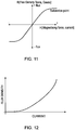
- Fig 11 shows a simplified B/H curve of magnetising force vs flux density for the soft magnet by itself.
- the force from the electropermanent magnet virtually goes to zero.
- the soft magnet would have to be brought to the zero flux point seen in Fig 11 .
- Fig 12 is a graph showing the flux density measured in an electropermanent magnet arrangement such as shown in Figs 2-5 . Current pulses were applied to the coil of the electropermanent magnet, at a number of different current values. After each pulse the coil was reset to zero flux density. Fig 12 is a curve which plots the flux density produced by each specific current pulse value, against the value of the current.
- Figs 13a and 13b show an example of how varying the transient activation or switching pulse amplitude can give a greater or lesser force from the electropermanent magnet and thus the brake.
- a first pulse 108 with a current of 40A is applied in a positive direction, applying the brake with 100% braking force as shown at 112 in Fig 13b .
- a second pulse 110 with a smaller current of 20A is applied in a negative direction. This reduces the braking force to 50% as shown at 114 in Fig 13b .
- Fig 14 is a schematic block diagram of a circuit for generating variable current pulses to implement this embodiment. It may be a modified version of the circuit of Fig 6 .
- the controller 8 of the machine in Fig 1 communicates with a programmable controller such as an FPGA 68. This produces signals to control a drive bridge 116, which produces the variable amplitude current pulses (positive and negative) to drive the coil 58 of the electropermanent magnet.
- the programmable controller 68 is programmed to produce current pulses of any desired amplitude and sign. It may also produce a programmable sequence of such current pulses with varying amplitudes and signs, as required.
- the drive bridge may for example include further drive transistors in addition to the transistors T1-T4 of Fig 6 . These can be switched on as desired to supply current pulses from intermediate voltages or through limiting resistors, depending on the value of current pulse required. Any number of current levels (either positive or negative) may be provided.
- the drive bridge 116 may be replaced by a completely variable current pulse generator, which produces current pulses of any desired amplitude and sign, as set by the programmable controller 68.
- Varying the available braking force from the electropermanent brake could be used for the following:
- the braking system has acted directly on the rotor 42 of the motor.
Description
- This invention relates to braking systems.
- One example where the use of a braking system may be desired is in position determining apparatus, e.g. for dimensional metrology. Such a position determining apparatus may comprise a movable member for holding a probe or other tool, which is movable in one, two or three dimensions relative to a fixed member or base in order to perform measurement or other operations on a workpiece. The movement may be driven by a motor or motors, or manually.
- Examples of such position determining apparatus include coordinate measuring machines (CMM), comparative gauging machines, machine tools, manual coordinate measuring arms and robots. The apparatus may be a so-called Cartesian machine, in which the movable member supporting the probe or other tool is mounted via three serially-connected carriages which are respectively movable in three orthogonal directions X,Y,Z. This is an example of a "serial kinematic" motion system. Alternatively, the measuring apparatus may be a non-Cartesian machine, for example having a "parallel kinematic" motion system comprising three or six extensible struts which are each connected in parallel between the movable member and the relatively fixed member or base. The motion of the movable member (and thus the probe or tool) in the X,Y,Z working volume is then controlled by coordinating the respective extensions of the three or six struts. An example of a non-Cartesian machine is shown in International Patent Applications
WO 03/006837 WO 2004/063579 . - Such apparatus may be provided with a braking system to prevent motion of the movable member when not in use. For example, this may prevent it sinking under gravity. In some circumstances it may also be important to apply the braking system to arrest the motion in a fail-safe manner, for example in the event of a power failure. This may prevent the movable member (or its probe or tool) crashing into something or someone, possibly causing damage or injury.
- Braking systems for other types of apparatus are known, in which a biasing force is applied to a braking element by a passive element such as a permanent magnet or a spring, to bias the braking element into an operative braking position. To release the braking element, an active element such as an electromagnetic coil is energised, counteracting the biasing force of the passive element. This provides fail-safe operation, since if the power to the active element fails then the passive element re-applies the biasing force to the braking element and the apparatus is braked. An example is shown in International Patent Application No.
WO 2014/132362 (which is related to US Patent Application No.US 2016/0015342, published later on 21 January 2016 ). - However, such arrangements require the active element (e.g. electromagnetic coil) to be energised at all times while the apparatus is in use. In the case of a position determining apparatus, this may cause thermal growth of parts of the apparatus. Such thermal growth adversely affects the accuracy of dimensional metrology. Continuous energisation is also a problem if energy efficiency is important, for example in battery-powered equipment such as portable measuring apparatus.
DE 3434116 A1 discloses an electromagnetic brake having a permanent magnet and electromagnet in combination with a spring, with a current pulse through the electromagnet causing the brake to be applied or released.DE 19752543 A1 discloses a similar type of arrangement.EP 1801535 A2 discloses an electromagnetic brake having a permanent magnet which is moved between two positions by operation of an electromagnet, thereby applying or releasing the brake. - The present invention provides a braking system according to claim 1 for braking a movable member, comprising:
- a braking element having an operative braking position in which it applies a braking force to the movable member, and an inoperative position in which the braking force is released; and
- an electrically-operated device arranged to switch the braking element between the operative and inoperative positions;
- wherein the electrically-operated device comprises:
- one or more active elements which are energisable by a transient pulse of electrical current to switch the braking element from the operative braking position to the inoperative position and from the inoperative position to the operative braking position; and
- one or more passive elements which maintain the braking element in the operative braking position and in the inoperative position, after the transient pulse has been removed from the active element or elements,
- and wherein the one or more passive elements include a soft permanent or semi-permanent magnet, the magnetic polarity of which is switchable by applying the transient pulse to one or more of the active elements, and a hard permanent magnet, wherein the magnetic polarity of the soft magnet is switchable by the transient pulse between a state of alignment with and a state of opposition to the magnetic polarity of the hard magnet.
- At least in the preferred embodiments, this avoids or reduces the need for continuous energisation to hold the braking element in the inoperative position during normal movement of the movable member. Possible advantages which result may include a limitation of thermal growth and/or increased energy efficiency.
- The electrically-operated device may be electro-magnetic, in which case its electro-magnetic force may be arranged to act on the braking element to switch it between the operative and inoperative positions. And/or the electrically-operated device may be coupled to the braking element mechanically.
- In one preferred embodiment, the braking device comprises an energy storage device (such as a capacitor) configured to supply the transient pulse to one or more of the active elements in the event of a power supply failure, to switch the braking element from the inoperative position to the operative braking position. This may provide fail-safe operation to brake the movement of the movable member in the event of a power supply failure. For example, the energy storage device may be a capacitor.
- Preferably, in the inoperative position, the one or more active elements are not energised. However, they may be energised by a current which is less than the transient pulse of electrical current.
- The one or more active elements may include an electromagnetic coil associated with the soft permanent magnet.
- The one or more passive elements may include a spring.
- The electro-magnetic device may be bistable or may include a bistable mechanism, whereby it is stable in both the operative and inoperative braking positions.
- Preferred embodiments of the invention will now be described by way of example, with reference to the accompanying drawings, wherein:
-
Fig 1 shows operative parts of a comparative gauging machine with a motion system using parallel kinematics; -
Fig 2 is an isometric view of part of an actuator and braking system in the machine ofFig 1 ; -
Fig 3 is a cross-sectional view ofFig 2 ; -
Figs 4 and 5 are diagrammatic representation of part of the braking system; -
Fig 6 is a schematic circuit diagram of a power supply circuit for the braking system; -
Figs 7, 8, 9 and 10 each show alternative braking systems toFigs 2 and 3 ; -
Fig 11 is graph showing flux density in a soft (semi-permanent) magnet; -
Fig 12 is a graph showing the flux density in an electropermanent magnet arrangement ofFigs 2-5 ; -
Figs 13a and 13b illustrate varying the activation or transient pulse amplitude in an arrangement according toFigs 2-5 ; and -
Fig 14 is a schematic block diagram of an alternative circuit for controlling a braking system. -
Fig 1 is an illustration of parts of a coordinate measuring apparatus. The apparatus is acomparative gauging machine 10 as sold by the present applicants Renishaw plc under the trademark EQUATOR. It comprises afixed platform 30 connected to amovable platform 32 by a non-Cartesian parallel kinematic motion system. In the present example, the parallel kinematic motion system comprises threestruts 34 which act in parallel between the fixed and movable platforms. The three struts 34 pass through threerespective actuators 36, by which they can be extended and retracted. One end of eachstrut 34 is mounted by a universally pivotable joint to themovable platform 32, and theactuators 36 are likewise universally pivotably mounted to the fixedplatform 30. - The
actuators 36 each comprise a motor for extending and retracting the respective strut, and a transducer which measures the extension of therespective strut 34. In each actuator 36, the transducer may be an encoder comprising a scale and readhead, with a counter for the output of the readhead. Each motor and transducer forms part of a respective servo loop controlled by a controller orcomputer 8. The motor may act through any suitable mechanism to extend and retract the strut, such as a rack and pinion. One preferred mechanism is a low-hysteresis drive with a toothed belt wrapped around a pinion on the motor spindle, for example in an Ω-shape maintained by an idler wheel or wheels. - The parallel kinematic motion system also comprises three passive
anti-rotation devices rigid plate 39 hinged to the fixedplatform 30 and a parallel, spaced pair ofrods 38 which are universally pivotably connected between therigid plate 39 and themovable platform 32. The anti-rotation devices cooperate to constrain themovable platform 32 against movement in all three rotational degrees of freedom. Therefore, themovable platform 32 is constrained to move only with three translational degrees of freedom X, Y, Z. By demanding appropriate extensions of thestruts 34, the controller/computer 8 can produce any desired X, Y, Z displacement or X, Y, Z positioning of the movable platform. - The principle of operation of such a parallel kinematic motion system is described in our
US Patent No. 5,813,287 (McMurtry et al ). It is an example of a tripod mechanism (having the three extending struts 34). Other motion systems e.g. with tripod or hexapod parallel kinematic mechanisms can be used. - Taken together, the transducers of the three actuators form a position measuring system. This determines the X, Y, Z position of the
movable platform 32 relative to the fixedplatform 30, by appropriate calculations in the controller orcomputer 8. These calculations are known to the skilled person. - Typically an
analogue probe 16 having adeflectable stylus 20 with aworkpiece contacting tip 22 is mounted on themovable platform 32 of the machine, although other types of probes (including touch trigger probes) may be used. The machine moves theprobe 16 relative to aworkpiece 14 on a table 12 in order to carry out measurements of features of the workpiece. The X, Y, Z position of a point on the workpiece surface is derived by calculation from the transducers in the servo system, in conjunction with the outputs of theanalogue probe 16. This is all controlled by the controller/computer 8. Alternatively, with a touch trigger probe, a signal indicating that the probe has contacted the surface of the workpiece freezes the X,Y,Z position value calculated from the output from the transducers and the computer takes a reading of the coordinates of the workpiece surface. If desired, for gauging operations during normal production use, automatic means such as a robot (not shown) may place each of a succession of substantially identical workpieces from a production run in at least nominally the same position and orientation on the table. - The parallel kinematic measuring apparatus of
Fig 1 is only one example of a type of apparatus in which the present invention can be used. Other examples include measuring apparatus with serial kinematic motion systems, such as a conventional Cartesian CMM with three serially-connected carriages which are movable orthogonally in XYZ directions. This could be computer controlled or manually operated. Another possible serial kinematic machine is an inspection robot or a manual articulating arm, with multiple articulating arm members connected serially by multiple rotary joints. The invention is also applicable to systems with linear motion in only one or two directions, and/or rotary motion about one or more axes. - Whichever type of machine is used, typically it is placed in a workshop environment in order to inspect production workpieces from an automated manufacturing process.
-
Figs 2 and 3 show a braking system which is included within each of theactuators 36. The motor in the actuator has arotor 42 mounted for rotation in ahousing 40. Aplanar spring 46 is mounted on the end of thehousing 40, and anannular brake pad 44 is mounted on one side of the planar spring, facing the rotor. Theplanar spring 46 has spiral cut-outs 48 so that the spring allows the brake pad to move axially towards and away from the rotor. In its normal relaxed state with no other forces acting, theplanar spring 46 acts as a passive element which holds thebrake pad 44 off therotor 42, so that the motor is free to rotate, extending and retracting thestrut 34. - An
electropermanent magnet assembly 50 is mounted on the other side of the planar spring, opposite the rotor. It has twoend plates 52, which extend through the planar spring to form a magnetic circuit with therotor 42. When the electropermanent magnet applies a magnetic force as described below, the end plates are pulled axially towards the rotor, deflecting the planar spring, and causing thebrake pad 44 to engage frictionally with therotor 42, applying a braking force. - As seen in
Figs 3, 4 and 5 , theelectropermanent magnet assembly 50 comprises a hard (permanent)magnet 54 and a soft (semi-permanent)magnet 56, arranged side-by-side in a parallel arrangement. They are surrounded by anelectromagnetic coil 58, which forms an active element. InFigs 4 and 5 , arrows indicate the magnetic polarities of the hard andsoft magnets hard magnet 54 may be made from a material such as sintered neodymium. The soft (semi-permanent)magnet 56 may be made of a material such as an AlNiCo alloy, with a coercivity chosen such that its magnetic polarity can be switched back and forth from one direction to the other by the application of a transient switching pulse (or activation pulse) of current through thecoil 58. Its magnetic polarity then remains in the reversed state with no applied current, until the application of another transient switching pulse of current in the opposite sense switches it back again. Meanwhile, the magnetic polarity of thehard magnet 54 is unaffected by these current pulses. -
Figs 4 and 5 show the two possible resulting bistable states of theelectropermanent magnet assembly 50. - In
Fig 4 , the polarities of themagnets end plates 52 and therotor 42, pulling thebrake pad 44 into frictional engagement with the rotor. Themagnets strut 34. - In
Fig 5 , after the polarity of thesoft magnet 56 has been switched by a pulse of current in thecoil 58, the polarities of the twomagnets assembly 50, passing from one magnet to the other via theend plates 52, but no longer passing through therotor 42. In this state, the brake is released, as theplanar spring 46 passively holds thebrake pad 44 off therotor 42. - Other arrangements are possible for the
assembly 50. For example, theelectromagnetic coil 58 could be wrapped around just themagnet 56 and not themagnet 54. And/or the hard andsoft magnets - It is notable that a pulse of current is only required to switch the electropermanent magnet from one state to the other, but not to keep it in either state thereafter. This means that during normal use of the coordinate measuring apparatus, with the brake released, there is no continuous current flow which might cause thermal growth of the
struts 34, causing an increase in their length and a resulting inaccuracy in the position of theprobe 16. It also means that when the brake is applied, it can prevent movement even if there is a power failure. - However, in some applications these issues may not be so important, and so a smaller residual current may continue to flow after the transient switching pulse. For example, in a particular application there may be a continuous trickle current in the
coil 58 if the heat produced is below that which would cause thermal growth sufficient to adversely affect the required accuracy of the apparatus. -
Fig 6 shows a circuit which provides the transient switching pulses of current to switch theelectropermanent magnet assembly 50 between the two states seen inFigs 4 and 5 . One of these circuits is provided for each of the threeactuators 36. - The circuit includes a field programmable gate array (FPGA) 68. The
FPGA 68 communicates (directly or through an intermediate master circuit) with themachine controller 8 via acommunications bus 70, and enables or disables the motor in therespective actuator 36, via amotor control 72. In normal operation the FPGA is configured to act on commands from thecontroller 8, to release the respective brake when the motor is to be driven, and to activate the brake when the motor is stopped. Optionally it may also receive manual inputs, e.g. from an emergency stop button to switch off the motors and apply the brakes in the event of an emergency. - The
FPGA 68 produces signals on aline 60 when the brake is to be activated, and on aline 62 when it is to be released. These signals drive theelectromagnetic coil 58 through a drive bridge comprising transistors T1, T2, T3 and T4. Since thecoil 58 uses a higher operating voltage than the FPGA, the signals to the high side transistors T1, T3 of the drive bridge pass thoughgate drivers - Power for the drive bridge comes from two reservoir capacitors C1, C2, which are trickle charged via a resistor R1 and respective Schottky diodes D1, D2. The capacitors each store a preset amount of energy when charged.
- When a 'release' signal is received from the FPGA on the
line 62, the transistors T1 and T2 are switched on and the capacitor C1 discharges through thecoil 58. This produces a pulse of current in the coil, causing thesoft magnet 56 to flip from the state shown inFig 4 to that shown inFig 5 . Thebrake pad 44 is released from therotor 42 of the motor. Normal unbraked operation of themachine 10 is possible. - After this transient switching pulse, the FPGA removes the 'release' signal from the
line 60, transistors T1, T2 turn off and capacitor C1 recharges. As discussed above, no further current passes through thecoil 58 during normal operation of themachine 10. So thermal growth of thestruts 34 and other parts of the machine is avoided, and energy is conserved (which may be advantageous in battery operated apparatus). - When an 'activate' signal is received from the FPGA on the
line 60, the transistors T3 and T4 are switched on and the capacitor C2 discharges through thecoil 58, with current flow in the opposite sense. This produces another pulse of current in the coil, causing thesoft magnet 56 to flip back from the state shown inFig 5 to that shown inFig 4 . Theend plates 52 are pulled towards therotor 42, and thebrake pad 44 is applied to brake the motion of therotor 42. Again, after this transient switching pulse, the FPGA removes the 'activate' signal from theline 60, the transistors T3, T4 turn off and capacitor C2 recharges. No further current passes through thecoil 58. - In the event of a power failure while the braking system is released, it is reactivated in a fail-safe manner as follows.
- An analogue to digital converter (ADC) 74 monitors the power supply voltage V+ to the machine 10 (e.g. 48V and 20V), via a suitable voltage divider (not shown). The
ADC 74 inputs a corresponding digital value to theFPGA 68. In the event of a power failure, the FPGA is programmed to issue an 'activate' signal online 60 when this digital value falls below a certain threshold, e.g. corresponding to a predetermined voltage lower than V+ or 20V. It also signals themotor control 72 to disable the motor. The FPGA and ADC are able to do this since their own power supply is regulated at a lower voltage still, e.g. 3.3V. This all happens very quickly in the short time before the power supply V+ drops below 3.3V and the operation of the FPGA is disrupted. - Thus, in the event of a power failure, this 'activate' signal switches on the transistors T3 and T4. (The
gate driver 64 includes a reservoir capacitor, not shown, which stores enough energy to switch on T3 as the power goes down). The capacitor C2 discharges through thecoil 58 via T3 and T4, supplying a pulse of current sufficient to flip thesoft magnet 56 to the state shown inFig 4 and activate the brake. Since no further current is required to maintain the soft magnet in the state shown inFig 4 , this ensures the fail-safe operation, to halt the motion of themachine 10 and prevent it crashing. - Although the above circuit uses an ADC and FPGA to detect a power failure, the same functionality could be achieved using simpler electronics if desired, e.g. a comparator circuit monitoring the power supply voltage. However, the FPGA has the advantage that the voltage threshold at which the braking system is activated can be programmable.
-
Fig 7 shows an alternative to the braking system ofFigs 2 and 3 , not embodying the present invention. As before, amotor rotor 42 is mounted for rotation in ahousing 40. Abrake pad 80 is mounted on the underside of aplanar spring 82. In this embodiment, theplanar spring 82 is in the form of a bistable diaphragm. It acts as a passive element which can naturally adopt either of two buckled positions. In the position shown in solid lines, thespring 82 urges thebrake pad 80 against therotor 42, to brake the motion of thestrut 34 of the machine. In the position indicated by abroken line 82a, thespring 82 holds the brake pad off therotor 42, and the brake is released. - To activate the brake, the diaphragm spring is flipped into the position shown in solid lines by a transient switching pulse of current in a solenoid coil 84 (which forms an active element). To release the brake, it is flipped into the position indicated by the
broken line 82a by another transient switching pulse of current in thecoil 84, in the opposite sense. Thediaphragm spring 82 thus enables the brake to be held in the activated or released condition without a continuous supply of power. The pulses of current to thecoil 84 may be supplied by a fail-safe circuit such as in the previous embodiment, which ensures that the brake is activated in the event of a power supply failure. -
Fig 8 shows a modified version of theFig 7 example, also not embodying the present invention, in which similar parts have been given the same reference numbers. Instead of a diaphragm planar spring, it has aplate 86 of a magnetic material such as steel, which can be flipped between activated and released positions. One ormore brake pads 88 are mounted to the underside of theplate 86. In the activated condition, one ormore magnets 90 on therotor 42 act as passive elements to attract theplate 86, urging the brake pads against the rotor. In the released condition, one ormore magnets 92 on acover 41 of the housing likewise act as passive elements to attract theplate 86, holding the pads away from the rotor. Theplate 86 is flipped between the activated and released positions by transient switching pulses of current in a solenoid coil (in opposite directions), as inFig 7 , with a similar fail-safe circuit to activate the brake if the power supply fails. This forms a bistable mechanism. Of course, instead of a steel plate, themagnets rotor 42 and thehousing cover 41. -
Fig 9 shows another modified example with a bistable mechanism, also not embodying the present invention. One ormore brake pads 88 are mounted on aplate 96, which again can be flipped between an activated position (solid lines) and a released position (broken lines 94a). It is flipped between these two stable positions by an over-centre mechanism comprising arotatable wheel 96 and aspring 98. In the activated position, the force of thespring 98 acts on theplate 94 through anarm 100 of the over-centre mechanism, urging the brake pads to brake the motion of themotor rotor 42. In the released position (broken lines), the over-centre mechanism holds the brake pads away from the rotor. The mechanism is flipped between the two positions by a solenoid, not shown, which may be similar toFigs 7 and 8 , including a fail-safe circuit. -
Fig 10 shows a further bistable example not embodying the present invention. Here, themotor rotor 42 is provided with aratchet 102, either on its outer periphery or on an element mounted to the rotor. This cooperates with apawl 104, hinged about apivot point 106. In the position shown, the pawl engages with the ratchet, to brake the motion of the rotor. It may be held in this position simply by friction at thehinge pivot point 106. Thepawl 104 is moved between activated and released positions by asolenoid coil 84. To release the brake, a transient pulse of current is supplied to the coil, disengaging the pawl from the ratchet. Again, friction at the pivot point holds the pawl in this position. To activate the brake, a transient pulse of current in the opposition direction engages the pawl with the ratchet. The solenoid may be similar toFigs 7 and 8 , including a fail-safe circuit. - The
Fig 10 example may be modified by providing a pin instead of the pawl, which engages in holes in the rotor periphery instead of a ratchet. Or the holes may be provided on an element mounted to the rotor, or to another movable part of the machine. Or the pin may be mounted to a movable part, engaging holes in a fixed part of the machine. The pawl or pin may be provided with a locking mechanism, activated and released by the solenoid, instead of relying on friction to hold it in the activated and released positions. - Other bistable mechanisms are of course possible. For example a hydraulic mechanism could apply and release brake pads, and could have a solenoid-operated valve or valves to keep it in the activated and released conditions without requiring a continuous current in operation.
- A further embodiment of the invention will now be described.
- In experiments with the embodiment of
Figs 2-5 , it has been observed that the amount of force available from the electropermanent magnet was reduced when the activation pulse current was reduced. This reduction in magnet force remains constant until the coil is pulsed again either increasing or decreasing the available force. In the further embodiment described below, this property is used to give advanced control over the brake function. In the prior art, an electromagnetic brake system typically is digital, on or off. With the electropermanent brake the force can be set to any point right the way up to saturation. - The maximum field strength from an electropermanent magnet such as shown in
Figs 2-5 is achieved when there is full polar alignment of the hard (permanent)neodymium magnet 54 and the soft (semi-permanent) AlNiCo magnet 56 (Fig 4 ). When the poles are opposed (Fig 5 ) the field strength will drop to virtually zero. -
Fig 11 shows a simplified B/H curve of magnetising force vs flux density for the soft magnet by itself. In the electropermanent arrangement ofFigs 2-5 , when the soft magnet passes from the positive flux zone to the negative flux zone, the force from the electropermanent magnet virtually goes to zero. To reduce the force to 50%, in theory the soft magnet would have to be brought to the zero flux point seen inFig 11 . - The B/H curve for an electropermanent magnet is quite different from
Fig 11 because the hard (permanent) magnet is not affected by the magnetic field of thecoil 58.Fig 12 is a graph showing the flux density measured in an electropermanent magnet arrangement such as shown inFigs 2-5 . Current pulses were applied to the coil of the electropermanent magnet, at a number of different current values. After each pulse the coil was reset to zero flux density.Fig 12 is a curve which plots the flux density produced by each specific current pulse value, against the value of the current. -
Figs 13a and 13b show an example of how varying the transient activation or switching pulse amplitude can give a greater or lesser force from the electropermanent magnet and thus the brake. InFig 13a , afirst pulse 108 with a current of 40A is applied in a positive direction, applying the brake with 100% braking force as shown at 112 inFig 13b . Subsequently, asecond pulse 110 with a smaller current of 20A is applied in a negative direction. This reduces the braking force to 50% as shown at 114 inFig 13b . - This contrasts with the above description of
Figs 2-5 , where the negative and positive pulses have the same current value (amplitude). In that case, the second pulse would reduce the braking force to zero, releasing the brake completely. - By varying the amplitudes of the activation (switching) pulses, it is possible to set the braking force from 0 to 100% on demand. This is a significant advantage over previously-known electromagnetic braking systems.
-
Fig 14 is a schematic block diagram of a circuit for generating variable current pulses to implement this embodiment. It may be a modified version of the circuit ofFig 6 . As inFig 6 , thecontroller 8 of the machine inFig 1 communicates with a programmable controller such as anFPGA 68. This produces signals to control adrive bridge 116, which produces the variable amplitude current pulses (positive and negative) to drive thecoil 58 of the electropermanent magnet. Theprogrammable controller 68 is programmed to produce current pulses of any desired amplitude and sign. It may also produce a programmable sequence of such current pulses with varying amplitudes and signs, as required. - In order to produce the current pulses at different positive and negative values, the drive bridge may for example include further drive transistors in addition to the transistors T1-T4 of
Fig 6 . These can be switched on as desired to supply current pulses from intermediate voltages or through limiting resistors, depending on the value of current pulse required. Any number of current levels (either positive or negative) may be provided. - Alternatively, the
drive bridge 116 may be replaced by a completely variable current pulse generator, which produces current pulses of any desired amplitude and sign, as set by theprogrammable controller 68. - Varying the available braking force from the electropermanent brake could be used for the following:
- Deceleration profiles: For example, a high initial brake force may drop to a lower force, giving maximum deceleration but allowing for back driving.
- Uniform reduced brake force: To simplify manufacture, it is possible to manufacture identical brakes which all have high force capabilities. However, on installation or initialisation of the brake, the activation pulse amplitude can then be set in the
programmable controller 68 to achieve a specific holding force. - Shipping and installation: It is not always desirable to ship a complete system such as shown in
Fig 1 with the brakes on, as this would hinder unpacking of the system. However, it is advantageous to have some resistance in the system to allow themovable platform 32 to hold position to aid installation. This can be achieved by pre-setting the brake with a desired braking force prior to shipment. - Counterbalance reduced braking requirements: A machine as shown in
Fig 1 may typically include a counterbalance mechanism, to prevent themovable platform 32 sinking under gravity. On installation of the counterbalance the mass at the movable platform will be reduced changing the braking dynamic. Changing the brake force would counter this effect. - In the embodiments described, the braking system has acted directly on the
rotor 42 of the motor. Of course, it is possible for it to act on any other moving part of the apparatus or machine which is to be braked, and this part could have either linear or rotary movement.
Claims (9)
- A braking system for braking a movable member (42), comprising:a braking element (44) having an operative braking position in which it applies a braking force to the movable member (42), and an inoperative position in which the braking force is released; andan electro-magnetic device (50), the electro-magnetic force of which is arranged to act on the braking element (44) to switch it between the operative and inoperative positions;wherein the electro-magnetic device (50) comprises:one or more active elements (58) which are energisable by a transient pulse of electrical current to switch the braking element from the operative braking position to the inoperative position and from the inoperative position to the operative braking position; andone or more passive elements (54, 56) which maintain the braking element (44) in the operative braking position and in the inoperative position, after the transient pulse has been removed from the active element or elements (58),characterised in that the one or more passive elements (54, 56) include a soft permanent or semi-permanent magnet (56), the magnetic polarity of which is switchable by applying the transient pulse to one or more of the active elements, and a hard permanent magnet (54), wherein the magnetic polarity of the soft magnet (56) is switchable by the transient pulse between a state of alignment with and a state of opposition to the magnetic polarity of the hard magnet (54).
- A braking system according to claim 1, comprising an energy storage device configured to supply the transient pulse to one or more of the active elements (58) in the event of a power supply failure, to switch the braking element (44) from the inoperative position to the operative braking position.
- A braking system according to claim 2, wherein the energy storage device comprises a capacitor.
- A braking system to any one of the preceding claims, wherein in the inoperative position, the one or more active elements (58) are either not energised or energised by a current which is less than the transient pulse of electrical current.
- A braking system according to any one of the preceding claims, wherein the one or more active elements (58) include an electromagnetic coil (58) associated with the soft permanent magnet (56).
- A braking system according to any one of the preceding claims, wherein the one or more passive elements include a spring (46).
- A braking system according to any one of the preceding claims, wherein the electro-magnetic device (50) is bistable or includes a bistable mechanism, whereby it is stable in both the operative and inoperative braking positions.
- A braking system according to any one of the preceding claims, including a control device for producing the transient pulse, which is capable of producing transient pulses of variable amplitude.
- A braking system according to claim 8, wherein the control device is programmable to produce a sequence of two or more transient pulses of different amplitudes.
Applications Claiming Priority (2)
| Application Number | Priority Date | Filing Date | Title |
|---|---|---|---|
| GBGB1515171.5A GB201515171D0 (en) | 2015-08-26 | 2015-08-26 | Braking system |
| PCT/GB2016/052673 WO2017033030A1 (en) | 2015-08-26 | 2016-08-26 | Braking system |
Publications (2)
| Publication Number | Publication Date |
|---|---|
| EP3341680A1 EP3341680A1 (en) | 2018-07-04 |
| EP3341680B1 true EP3341680B1 (en) | 2019-07-31 |
Family
ID=54292239
Family Applications (1)
| Application Number | Title | Priority Date | Filing Date |
|---|---|---|---|
| EP16759847.3A Active EP3341680B1 (en) | 2015-08-26 | 2016-08-26 | Braking system |
Country Status (6)
| Country | Link |
|---|---|
| US (1) | US10527411B2 (en) |
| EP (1) | EP3341680B1 (en) |
| JP (1) | JP6827465B2 (en) |
| CN (1) | CN108351204B (en) |
| GB (1) | GB201515171D0 (en) |
| WO (1) | WO2017033030A1 (en) |
Families Citing this family (4)
| Publication number | Priority date | Publication date | Assignee | Title |
|---|---|---|---|---|
| GB201513850D0 (en) | 2015-08-05 | 2015-09-16 | Renishaw Plc | Coordinate positioning machine |
| SE541388C2 (en) * | 2017-12-19 | 2019-09-10 | Assa Abloy Ab | Actuator comprising electro permanent magnet and method |
| JP7040287B2 (en) * | 2018-05-25 | 2022-03-23 | トヨタ自動車株式会社 | Vehicle braking device |
| EP4265380A1 (en) * | 2022-04-21 | 2023-10-25 | Microsure B.V. | Joint arrangement for a robot arm for providing an energy-efficient braking function |
Family Cites Families (33)
| Publication number | Priority date | Publication date | Assignee | Title |
|---|---|---|---|---|
| US1303331A (en) * | 1919-05-13 | Window | ||
| NL268917A (en) | 1960-09-09 | 1964-06-25 | Sirugue & Cie | Control device for starting workpieces to be machined, in particular for a punching machine |
| GB1218032A (en) * | 1967-09-21 | 1971-01-06 | Int Computers Ltd | Electronic control circuits for electromagnetic devices |
| US3516526A (en) | 1968-06-17 | 1970-06-23 | Singer Co | Control circuits for electromagnetic clutch-brake driving devices |
| DE1763853B2 (en) | 1968-08-23 | 1977-10-20 | Quick Rotan Becker & Notz KG, 6100 Darmstadt | ELECTRIC DRIVE |
| FR2135689A5 (en) * | 1971-03-09 | 1972-12-22 | Potain Sa | |
| US3730317A (en) * | 1971-07-21 | 1973-05-01 | Eaton Corp | Electromagnetic coupling with permanent magnets |
| US3818596A (en) | 1973-03-29 | 1974-06-25 | Bendix Corp | Counterbalance for a vertically supported probe shaft |
| US4283657A (en) | 1976-03-25 | 1981-08-11 | Lampiridae Associates | Exit illuminating system |
| JPS6022805B2 (en) * | 1977-08-23 | 1985-06-04 | オリンパス光学工業株式会社 | Electromagnetic device for releasing restraint |
| JPS60130106A (en) * | 1983-12-16 | 1985-07-11 | Sumitomo Special Metals Co Ltd | Permanent electromagnetic attracting device |
| DE3434116C2 (en) * | 1984-09-17 | 1986-11-20 | Fa. Carl Zeiss, 7920 Heidenheim | Electromagnetic brake |
| JP2701321B2 (en) * | 1988-05-31 | 1998-01-21 | 神鋼電機株式会社 | Electromagnetic brake |
| US5813287A (en) | 1994-03-02 | 1998-09-29 | Renishaw Plc | Coordinate positioning machine |
| AT405074B (en) * | 1995-07-13 | 1999-05-25 | Rudolf Liberda | GATE, ESPECIALLY SLIDING GATE |
| AU3555497A (en) | 1997-08-04 | 1999-03-01 | Railfix N.V. | Lifter with electropermanent magnets provided with a safety device |
| DE19752543A1 (en) * | 1997-11-27 | 1999-06-02 | Bosch Gmbh Robert | Magnetic brake and electromechanical braking device with a magnetic brake |
| GB0117098D0 (en) | 2001-07-13 | 2001-09-05 | Renishaw Plc | Pivot joint |
| JP4851716B2 (en) | 2003-01-15 | 2012-01-11 | レニショウ パブリック リミテッド カンパニー | Pivot joint |
| JP2005140165A (en) * | 2003-11-04 | 2005-06-02 | Sumitomo Electric Ind Ltd | Electric brake |
| GB0421924D0 (en) | 2004-10-01 | 2004-11-03 | Copley Motion Systems Llc | Linear motor brake |
| US7969705B2 (en) * | 2005-03-30 | 2011-06-28 | Strattec Security Corporation | Residual magnetic devices and methods |
| US7401483B2 (en) * | 2005-03-30 | 2008-07-22 | Strattec Security Corporation | Residual magnetic devices and methods for an ignition actuation blockage device |
| DE102005063242B4 (en) * | 2005-12-20 | 2011-01-13 | Carl Zeiss Industrielle Messtechnik Gmbh | Magnetic coupling, in particular for locking a rotary joint in a coordinate measuring machine |
| JP2007192785A (en) * | 2006-01-17 | 2007-08-02 | Masataka Tsurumi | Motor-driven servo cylinder with absolute position detector |
| US7610719B2 (en) * | 2006-07-19 | 2009-11-03 | Chung Hsien Hsieh | Active brake release device attached to the exterior of a door controller |
| JP4563429B2 (en) * | 2007-08-08 | 2010-10-13 | 株式会社日立製作所 | Brake control device |
| US8376612B2 (en) | 2008-02-22 | 2013-02-19 | Hitachi Medical Corporation | Mobile X-ray apparatus |
| CN102214980A (en) * | 2010-04-01 | 2011-10-12 | 戴珊珊 | Method and device for generating mechanical reciprocating bistable motion by virtue of electromagnetism |
| WO2014132362A1 (en) | 2013-02-27 | 2014-09-04 | 株式会社島津製作所 | X-ray imaging device |
| US9297430B2 (en) * | 2013-07-02 | 2016-03-29 | Goodrich Corporation | Wrap spring park brake system, apparatus and method |
| JP2015021529A (en) * | 2013-07-17 | 2015-02-02 | 株式会社日立製作所 | Electromagnetic brake device |
| US9586678B2 (en) * | 2015-01-15 | 2017-03-07 | United Technologies Corporation | Bi-stable voice coil park brake |
-
2015
- 2015-08-26 GB GBGB1515171.5A patent/GB201515171D0/en not_active Ceased
-
2016
- 2016-08-26 WO PCT/GB2016/052673 patent/WO2017033030A1/en active Application Filing
- 2016-08-26 CN CN201680062397.4A patent/CN108351204B/en active Active
- 2016-08-26 JP JP2018510390A patent/JP6827465B2/en active Active
- 2016-08-26 US US15/750,473 patent/US10527411B2/en active Active
- 2016-08-26 EP EP16759847.3A patent/EP3341680B1/en active Active
Non-Patent Citations (1)
| Title |
|---|
| None * |
Also Published As
| Publication number | Publication date |
|---|---|
| GB201515171D0 (en) | 2015-10-07 |
| JP2018532954A (en) | 2018-11-08 |
| US10527411B2 (en) | 2020-01-07 |
| WO2017033030A1 (en) | 2017-03-02 |
| JP6827465B2 (en) | 2021-02-10 |
| US20180224272A1 (en) | 2018-08-09 |
| EP3341680A1 (en) | 2018-07-04 |
| CN108351204B (en) | 2020-06-02 |
| CN108351204A (en) | 2018-07-31 |
Similar Documents
| Publication | Publication Date | Title |
|---|---|---|
| EP3341680B1 (en) | Braking system | |
| US9636827B2 (en) | Robot system for performing force control | |
| US10987870B2 (en) | Printing system for three-dimensional objects | |
| EP3280569B1 (en) | System and method for adjusting end-effector actuation based on relative position with respect to gravitational force | |
| CN105364565A (en) | Conformable electroadhesive holding device | |
| CN110497385A (en) | The device and method of accurate measurement six-degree-of-freedom parallel connection mechanism moving platform pose | |
| US10189159B1 (en) | Methods and systems for detecting states of operation of a robotic device | |
| US10300602B2 (en) | Method and means for handling an object | |
| US20040017170A1 (en) | Electric actuator and method of controlling the same | |
| CN113172511A (en) | Robot polishing actuator based on constant force mechanism | |
| CN116061152A (en) | Robot, method for controlling the same, method for manufacturing article, and storage medium | |
| EP0921456B1 (en) | Control processes for linear voice coil actuator | |
| EP4086039A1 (en) | A motorised measurement arm apparatus for a machine tool | |
| EP3690277B1 (en) | Couplings that actively stabilize vibrations | |
| JP4538653B2 (en) | Micro processing equipment | |
| CN109844477A (en) | External force detection method | |
| JP2014185877A (en) | Force sensor evaluation device and force sensor evaluation method | |
| Lemieux et al. | Force control test bench for underwater vehicle-manipulator system applications | |
| CN217475950U (en) | Industrial robot | |
| JP7305298B2 (en) | Force sensor, force sensor control method, robot system, robot system control method, article manufacturing method using robot system, control program, and recording medium | |
| DeLuca et al. | Force-based interaction for distributed precision assembly | |
| US20230109495A1 (en) | Method and Apparatus for Positional Reference in an Automated Manufacturing System | |
| RU88131U1 (en) | MEASURING HEAD | |
| JP2023083982A (en) | Robot, robot control method, article production method using robot, control program, and recording medium | |
| Tanaka et al. | Study of force-driven pneumatic joystick |
Legal Events
| Date | Code | Title | Description |
|---|---|---|---|
| STAA | Information on the status of an ep patent application or granted ep patent |
Free format text: STATUS: THE INTERNATIONAL PUBLICATION HAS BEEN MADE |
|
| PUAI | Public reference made under article 153(3) epc to a published international application that has entered the european phase |
Free format text: ORIGINAL CODE: 0009012 |
|
| STAA | Information on the status of an ep patent application or granted ep patent |
Free format text: STATUS: REQUEST FOR EXAMINATION WAS MADE |
|
| 17P | Request for examination filed |
Effective date: 20180306 |
|
| AK | Designated contracting states |
Kind code of ref document: A1 Designated state(s): AL AT BE BG CH CY CZ DE DK EE ES FI FR GB GR HR HU IE IS IT LI LT LU LV MC MK MT NL NO PL PT RO RS SE SI SK SM TR |
|
| AX | Request for extension of the european patent |
Extension state: BA ME |
|
| DAV | Request for validation of the european patent (deleted) | ||
| DAX | Request for extension of the european patent (deleted) | ||
| GRAP | Despatch of communication of intention to grant a patent |
Free format text: ORIGINAL CODE: EPIDOSNIGR1 |
|
| STAA | Information on the status of an ep patent application or granted ep patent |
Free format text: STATUS: GRANT OF PATENT IS INTENDED |
|
| INTG | Intention to grant announced |
Effective date: 20190307 |
|
| GRAS | Grant fee paid |
Free format text: ORIGINAL CODE: EPIDOSNIGR3 |
|
| GRAA | (expected) grant |
Free format text: ORIGINAL CODE: 0009210 |
|
| STAA | Information on the status of an ep patent application or granted ep patent |
Free format text: STATUS: THE PATENT HAS BEEN GRANTED |
|
| AK | Designated contracting states |
Kind code of ref document: B1 Designated state(s): AL AT BE BG CH CY CZ DE DK EE ES FI FR GB GR HR HU IE IS IT LI LT LU LV MC MK MT NL NO PL PT RO RS SE SI SK SM TR |
|
| REG | Reference to a national code |
Ref country code: CH Ref legal event code: EP Ref country code: GB Ref legal event code: FG4D |
|
| REG | Reference to a national code |
Ref country code: DE Ref legal event code: R096 Ref document number: 602016017783 Country of ref document: DE |
|
| REG | Reference to a national code |
Ref country code: AT Ref legal event code: REF Ref document number: 1161380 Country of ref document: AT Kind code of ref document: T Effective date: 20190815 |
|
| REG | Reference to a national code |
Ref country code: IE Ref legal event code: FG4D |
|
| REG | Reference to a national code |
Ref country code: NL Ref legal event code: MP Effective date: 20190731 |
|
| REG | Reference to a national code |
Ref country code: LT Ref legal event code: MG4D |
|
| REG | Reference to a national code |
Ref country code: AT Ref legal event code: MK05 Ref document number: 1161380 Country of ref document: AT Kind code of ref document: T Effective date: 20190731 |
|
| PG25 | Lapsed in a contracting state [announced via postgrant information from national office to epo] |
Ref country code: FI Free format text: LAPSE BECAUSE OF FAILURE TO SUBMIT A TRANSLATION OF THE DESCRIPTION OR TO PAY THE FEE WITHIN THE PRESCRIBED TIME-LIMIT Effective date: 20190731 Ref country code: LT Free format text: LAPSE BECAUSE OF FAILURE TO SUBMIT A TRANSLATION OF THE DESCRIPTION OR TO PAY THE FEE WITHIN THE PRESCRIBED TIME-LIMIT Effective date: 20190731 Ref country code: HR Free format text: LAPSE BECAUSE OF FAILURE TO SUBMIT A TRANSLATION OF THE DESCRIPTION OR TO PAY THE FEE WITHIN THE PRESCRIBED TIME-LIMIT Effective date: 20190731 Ref country code: SE Free format text: LAPSE BECAUSE OF FAILURE TO SUBMIT A TRANSLATION OF THE DESCRIPTION OR TO PAY THE FEE WITHIN THE PRESCRIBED TIME-LIMIT Effective date: 20190731 Ref country code: NO Free format text: LAPSE BECAUSE OF FAILURE TO SUBMIT A TRANSLATION OF THE DESCRIPTION OR TO PAY THE FEE WITHIN THE PRESCRIBED TIME-LIMIT Effective date: 20191031 Ref country code: NL Free format text: LAPSE BECAUSE OF FAILURE TO SUBMIT A TRANSLATION OF THE DESCRIPTION OR TO PAY THE FEE WITHIN THE PRESCRIBED TIME-LIMIT Effective date: 20190731 Ref country code: BG Free format text: LAPSE BECAUSE OF FAILURE TO SUBMIT A TRANSLATION OF THE DESCRIPTION OR TO PAY THE FEE WITHIN THE PRESCRIBED TIME-LIMIT Effective date: 20191031 Ref country code: AT Free format text: LAPSE BECAUSE OF FAILURE TO SUBMIT A TRANSLATION OF THE DESCRIPTION OR TO PAY THE FEE WITHIN THE PRESCRIBED TIME-LIMIT Effective date: 20190731 Ref country code: PT Free format text: LAPSE BECAUSE OF FAILURE TO SUBMIT A TRANSLATION OF THE DESCRIPTION OR TO PAY THE FEE WITHIN THE PRESCRIBED TIME-LIMIT Effective date: 20191202 |
|
| PG25 | Lapsed in a contracting state [announced via postgrant information from national office to epo] |
Ref country code: IS Free format text: LAPSE BECAUSE OF FAILURE TO SUBMIT A TRANSLATION OF THE DESCRIPTION OR TO PAY THE FEE WITHIN THE PRESCRIBED TIME-LIMIT Effective date: 20191130 Ref country code: ES Free format text: LAPSE BECAUSE OF FAILURE TO SUBMIT A TRANSLATION OF THE DESCRIPTION OR TO PAY THE FEE WITHIN THE PRESCRIBED TIME-LIMIT Effective date: 20190731 Ref country code: GR Free format text: LAPSE BECAUSE OF FAILURE TO SUBMIT A TRANSLATION OF THE DESCRIPTION OR TO PAY THE FEE WITHIN THE PRESCRIBED TIME-LIMIT Effective date: 20191101 Ref country code: LV Free format text: LAPSE BECAUSE OF FAILURE TO SUBMIT A TRANSLATION OF THE DESCRIPTION OR TO PAY THE FEE WITHIN THE PRESCRIBED TIME-LIMIT Effective date: 20190731 Ref country code: AL Free format text: LAPSE BECAUSE OF FAILURE TO SUBMIT A TRANSLATION OF THE DESCRIPTION OR TO PAY THE FEE WITHIN THE PRESCRIBED TIME-LIMIT Effective date: 20190731 Ref country code: RS Free format text: LAPSE BECAUSE OF FAILURE TO SUBMIT A TRANSLATION OF THE DESCRIPTION OR TO PAY THE FEE WITHIN THE PRESCRIBED TIME-LIMIT Effective date: 20190731 |
|
| PG25 | Lapsed in a contracting state [announced via postgrant information from national office to epo] |
Ref country code: TR Free format text: LAPSE BECAUSE OF FAILURE TO SUBMIT A TRANSLATION OF THE DESCRIPTION OR TO PAY THE FEE WITHIN THE PRESCRIBED TIME-LIMIT Effective date: 20190731 |
|
| PG25 | Lapsed in a contracting state [announced via postgrant information from national office to epo] |
Ref country code: PL Free format text: LAPSE BECAUSE OF FAILURE TO SUBMIT A TRANSLATION OF THE DESCRIPTION OR TO PAY THE FEE WITHIN THE PRESCRIBED TIME-LIMIT Effective date: 20190731 Ref country code: EE Free format text: LAPSE BECAUSE OF FAILURE TO SUBMIT A TRANSLATION OF THE DESCRIPTION OR TO PAY THE FEE WITHIN THE PRESCRIBED TIME-LIMIT Effective date: 20190731 Ref country code: RO Free format text: LAPSE BECAUSE OF FAILURE TO SUBMIT A TRANSLATION OF THE DESCRIPTION OR TO PAY THE FEE WITHIN THE PRESCRIBED TIME-LIMIT Effective date: 20190731 Ref country code: DK Free format text: LAPSE BECAUSE OF FAILURE TO SUBMIT A TRANSLATION OF THE DESCRIPTION OR TO PAY THE FEE WITHIN THE PRESCRIBED TIME-LIMIT Effective date: 20190731 |
|
| PG25 | Lapsed in a contracting state [announced via postgrant information from national office to epo] |
Ref country code: SK Free format text: LAPSE BECAUSE OF FAILURE TO SUBMIT A TRANSLATION OF THE DESCRIPTION OR TO PAY THE FEE WITHIN THE PRESCRIBED TIME-LIMIT Effective date: 20190731 Ref country code: LI Free format text: LAPSE BECAUSE OF NON-PAYMENT OF DUE FEES Effective date: 20190831 Ref country code: SM Free format text: LAPSE BECAUSE OF FAILURE TO SUBMIT A TRANSLATION OF THE DESCRIPTION OR TO PAY THE FEE WITHIN THE PRESCRIBED TIME-LIMIT Effective date: 20190731 Ref country code: IS Free format text: LAPSE BECAUSE OF FAILURE TO SUBMIT A TRANSLATION OF THE DESCRIPTION OR TO PAY THE FEE WITHIN THE PRESCRIBED TIME-LIMIT Effective date: 20200224 Ref country code: MC Free format text: LAPSE BECAUSE OF FAILURE TO SUBMIT A TRANSLATION OF THE DESCRIPTION OR TO PAY THE FEE WITHIN THE PRESCRIBED TIME-LIMIT Effective date: 20190731 Ref country code: LU Free format text: LAPSE BECAUSE OF NON-PAYMENT OF DUE FEES Effective date: 20190826 Ref country code: CH Free format text: LAPSE BECAUSE OF NON-PAYMENT OF DUE FEES Effective date: 20190831 Ref country code: CZ Free format text: LAPSE BECAUSE OF FAILURE TO SUBMIT A TRANSLATION OF THE DESCRIPTION OR TO PAY THE FEE WITHIN THE PRESCRIBED TIME-LIMIT Effective date: 20190731 |
|
| REG | Reference to a national code |
Ref country code: BE Ref legal event code: MM Effective date: 20190831 |
|
| REG | Reference to a national code |
Ref country code: DE Ref legal event code: R097 Ref document number: 602016017783 Country of ref document: DE |
|
| PLBE | No opposition filed within time limit |
Free format text: ORIGINAL CODE: 0009261 |
|
| STAA | Information on the status of an ep patent application or granted ep patent |
Free format text: STATUS: NO OPPOSITION FILED WITHIN TIME LIMIT |
|
| PG2D | Information on lapse in contracting state deleted |
Ref country code: IS |
|
| PG25 | Lapsed in a contracting state [announced via postgrant information from national office to epo] |
Ref country code: IE Free format text: LAPSE BECAUSE OF NON-PAYMENT OF DUE FEES Effective date: 20190826 Ref country code: IS Free format text: LAPSE BECAUSE OF FAILURE TO SUBMIT A TRANSLATION OF THE DESCRIPTION OR TO PAY THE FEE WITHIN THE PRESCRIBED TIME-LIMIT Effective date: 20191030 |
|
| 26N | No opposition filed |
Effective date: 20200603 |
|
| PG25 | Lapsed in a contracting state [announced via postgrant information from national office to epo] |
Ref country code: BE Free format text: LAPSE BECAUSE OF NON-PAYMENT OF DUE FEES Effective date: 20190831 Ref country code: SI Free format text: LAPSE BECAUSE OF FAILURE TO SUBMIT A TRANSLATION OF THE DESCRIPTION OR TO PAY THE FEE WITHIN THE PRESCRIBED TIME-LIMIT Effective date: 20190731 |
|
| PG25 | Lapsed in a contracting state [announced via postgrant information from national office to epo] |
Ref country code: FR Free format text: LAPSE BECAUSE OF NON-PAYMENT OF DUE FEES Effective date: 20190930 |
|
| PG25 | Lapsed in a contracting state [announced via postgrant information from national office to epo] |
Ref country code: CY Free format text: LAPSE BECAUSE OF FAILURE TO SUBMIT A TRANSLATION OF THE DESCRIPTION OR TO PAY THE FEE WITHIN THE PRESCRIBED TIME-LIMIT Effective date: 20190731 |
|
| PG25 | Lapsed in a contracting state [announced via postgrant information from national office to epo] |
Ref country code: MT Free format text: LAPSE BECAUSE OF FAILURE TO SUBMIT A TRANSLATION OF THE DESCRIPTION OR TO PAY THE FEE WITHIN THE PRESCRIBED TIME-LIMIT Effective date: 20190731 Ref country code: HU Free format text: LAPSE BECAUSE OF FAILURE TO SUBMIT A TRANSLATION OF THE DESCRIPTION OR TO PAY THE FEE WITHIN THE PRESCRIBED TIME-LIMIT; INVALID AB INITIO Effective date: 20160826 |
|
| PG25 | Lapsed in a contracting state [announced via postgrant information from national office to epo] |
Ref country code: MK Free format text: LAPSE BECAUSE OF FAILURE TO SUBMIT A TRANSLATION OF THE DESCRIPTION OR TO PAY THE FEE WITHIN THE PRESCRIBED TIME-LIMIT Effective date: 20190731 |
|
| P01 | Opt-out of the competence of the unified patent court (upc) registered |
Effective date: 20230602 |
|
| PGFP | Annual fee paid to national office [announced via postgrant information from national office to epo] |
Ref country code: IT Payment date: 20230822 Year of fee payment: 8 Ref country code: GB Payment date: 20230822 Year of fee payment: 8 |
|
| PGFP | Annual fee paid to national office [announced via postgrant information from national office to epo] |
Ref country code: DE Payment date: 20230828 Year of fee payment: 8 |