EP3340927B1 - System zur intraossären befestigung eines flexiblen drahts zur verankerung von bändergewebe an knochen - Google Patents
System zur intraossären befestigung eines flexiblen drahts zur verankerung von bändergewebe an knochen Download PDFInfo
- Publication number
- EP3340927B1 EP3340927B1 EP16763464.1A EP16763464A EP3340927B1 EP 3340927 B1 EP3340927 B1 EP 3340927B1 EP 16763464 A EP16763464 A EP 16763464A EP 3340927 B1 EP3340927 B1 EP 3340927B1
- Authority
- EP
- European Patent Office
- Prior art keywords
- screw
- bone
- wire
- graft
- corpuscles
- Prior art date
- Legal status (The legal status is an assumption and is not a legal conclusion. Google has not performed a legal analysis and makes no representation as to the accuracy of the status listed.)
- Active
Links
Images




Classifications
-
- A—HUMAN NECESSITIES
- A61—MEDICAL OR VETERINARY SCIENCE; HYGIENE
- A61F—FILTERS IMPLANTABLE INTO BLOOD VESSELS; PROSTHESES; DEVICES PROVIDING PATENCY TO, OR PREVENTING COLLAPSING OF, TUBULAR STRUCTURES OF THE BODY, e.g. STENTS; ORTHOPAEDIC, NURSING OR CONTRACEPTIVE DEVICES; FOMENTATION; TREATMENT OR PROTECTION OF EYES OR EARS; BANDAGES, DRESSINGS OR ABSORBENT PADS; FIRST-AID KITS
- A61F2/00—Filters implantable into blood vessels; Prostheses, i.e. artificial substitutes or replacements for parts of the body; Appliances for connecting them with the body; Devices providing patency to, or preventing collapsing of, tubular structures of the body, e.g. stents
- A61F2/02—Prostheses implantable into the body
- A61F2/08—Muscles; Tendons; Ligaments
- A61F2/0811—Fixation devices for tendons or ligaments
-
- A—HUMAN NECESSITIES
- A61—MEDICAL OR VETERINARY SCIENCE; HYGIENE
- A61B—DIAGNOSIS; SURGERY; IDENTIFICATION
- A61B17/00—Surgical instruments, devices or methods
- A61B17/04—Surgical instruments, devices or methods for suturing wounds; Holders or packages for needles or suture materials
- A61B17/0401—Suture anchors, buttons or pledgets, i.e. means for attaching sutures to bone, cartilage or soft tissue; Instruments for applying or removing suture anchors
-
- A—HUMAN NECESSITIES
- A61—MEDICAL OR VETERINARY SCIENCE; HYGIENE
- A61B—DIAGNOSIS; SURGERY; IDENTIFICATION
- A61B17/00—Surgical instruments, devices or methods
- A61B17/04—Surgical instruments, devices or methods for suturing wounds; Holders or packages for needles or suture materials
- A61B17/06—Needles ; Sutures; Needle-suture combinations; Holders or packages for needles or suture materials
-
- A—HUMAN NECESSITIES
- A61—MEDICAL OR VETERINARY SCIENCE; HYGIENE
- A61B—DIAGNOSIS; SURGERY; IDENTIFICATION
- A61B17/00—Surgical instruments, devices or methods
- A61B17/04—Surgical instruments, devices or methods for suturing wounds; Holders or packages for needles or suture materials
- A61B17/0401—Suture anchors, buttons or pledgets, i.e. means for attaching sutures to bone, cartilage or soft tissue; Instruments for applying or removing suture anchors
- A61B2017/044—Suture anchors, buttons or pledgets, i.e. means for attaching sutures to bone, cartilage or soft tissue; Instruments for applying or removing suture anchors with a threaded shaft, e.g. screws
-
- A—HUMAN NECESSITIES
- A61—MEDICAL OR VETERINARY SCIENCE; HYGIENE
- A61B—DIAGNOSIS; SURGERY; IDENTIFICATION
- A61B17/00—Surgical instruments, devices or methods
- A61B17/04—Surgical instruments, devices or methods for suturing wounds; Holders or packages for needles or suture materials
- A61B17/06—Needles ; Sutures; Needle-suture combinations; Holders or packages for needles or suture materials
- A61B17/06166—Sutures
- A61B2017/06176—Sutures with protrusions, e.g. barbs
-
- A—HUMAN NECESSITIES
- A61—MEDICAL OR VETERINARY SCIENCE; HYGIENE
- A61F—FILTERS IMPLANTABLE INTO BLOOD VESSELS; PROSTHESES; DEVICES PROVIDING PATENCY TO, OR PREVENTING COLLAPSING OF, TUBULAR STRUCTURES OF THE BODY, e.g. STENTS; ORTHOPAEDIC, NURSING OR CONTRACEPTIVE DEVICES; FOMENTATION; TREATMENT OR PROTECTION OF EYES OR EARS; BANDAGES, DRESSINGS OR ABSORBENT PADS; FIRST-AID KITS
- A61F2/00—Filters implantable into blood vessels; Prostheses, i.e. artificial substitutes or replacements for parts of the body; Appliances for connecting them with the body; Devices providing patency to, or preventing collapsing of, tubular structures of the body, e.g. stents
- A61F2/02—Prostheses implantable into the body
- A61F2/08—Muscles; Tendons; Ligaments
- A61F2/0811—Fixation devices for tendons or ligaments
- A61F2002/0847—Mode of fixation of anchor to tendon or ligament
- A61F2002/0852—Fixation of a loop or U-turn, e.g. eyelets, anchor having multiple holes
-
- A—HUMAN NECESSITIES
- A61—MEDICAL OR VETERINARY SCIENCE; HYGIENE
- A61F—FILTERS IMPLANTABLE INTO BLOOD VESSELS; PROSTHESES; DEVICES PROVIDING PATENCY TO, OR PREVENTING COLLAPSING OF, TUBULAR STRUCTURES OF THE BODY, e.g. STENTS; ORTHOPAEDIC, NURSING OR CONTRACEPTIVE DEVICES; FOMENTATION; TREATMENT OR PROTECTION OF EYES OR EARS; BANDAGES, DRESSINGS OR ABSORBENT PADS; FIRST-AID KITS
- A61F2/00—Filters implantable into blood vessels; Prostheses, i.e. artificial substitutes or replacements for parts of the body; Appliances for connecting them with the body; Devices providing patency to, or preventing collapsing of, tubular structures of the body, e.g. stents
- A61F2/02—Prostheses implantable into the body
- A61F2/08—Muscles; Tendons; Ligaments
- A61F2/0811—Fixation devices for tendons or ligaments
- A61F2002/0847—Mode of fixation of anchor to tendon or ligament
- A61F2002/0858—Fixation of tendon or ligament between anchor and bone, e.g. interference screws, wedges
-
- A—HUMAN NECESSITIES
- A61—MEDICAL OR VETERINARY SCIENCE; HYGIENE
- A61F—FILTERS IMPLANTABLE INTO BLOOD VESSELS; PROSTHESES; DEVICES PROVIDING PATENCY TO, OR PREVENTING COLLAPSING OF, TUBULAR STRUCTURES OF THE BODY, e.g. STENTS; ORTHOPAEDIC, NURSING OR CONTRACEPTIVE DEVICES; FOMENTATION; TREATMENT OR PROTECTION OF EYES OR EARS; BANDAGES, DRESSINGS OR ABSORBENT PADS; FIRST-AID KITS
- A61F2/00—Filters implantable into blood vessels; Prostheses, i.e. artificial substitutes or replacements for parts of the body; Appliances for connecting them with the body; Devices providing patency to, or preventing collapsing of, tubular structures of the body, e.g. stents
- A61F2/02—Prostheses implantable into the body
- A61F2/08—Muscles; Tendons; Ligaments
- A61F2/0811—Fixation devices for tendons or ligaments
- A61F2002/0876—Position of anchor in respect to the bone
- A61F2002/0882—Anchor in or on top of a bone tunnel, i.e. a hole running through the entire bone
Definitions
- Bone anchoring of soft tissues of the capsular or ligamentous type constitutes one of the most frequent surgical imperatives after sports trauma.
- the fixation of a ligament graft in the bone tissue in order to reconstruct the torn anterior cruciate ligament is one of the most frequent (but not exclusive) examples of this type of surgical procedure. This application was chosen to explain the present invention but it goes without saying that it can also be applied to other anatomical structures.
- ACL anterior cruciate ligament
- patellar tendon grafts are considered more mechanically efficient, DIDT grafts are increasingly used because the adverse side effects associated with their harvest are generally less severe than with patellar tendon grafts.
- DIDT grafts are constructed by folding each of the two harvested tendons (internal rectus and semitendinosus) back on themselves in the middle to obtain a four-strand tendon graft measuring approximately 12 to 15 cm. Since the length of the cruciate ligament to be reconstructed is only approximately 3 cm, we realize that 70 to 80% of the harvested tendon substance is used only to fix the useful length of the graft (3 cm intra-articular).
- the reduced quantity of ligament tissue introduced into the bone no longer allows the use of conventional fixation methods such as compression of the graft in the bone tunnel by a tightening screw introduced between the graft and the inner wall of the bone tunnel (interference screw) or suspension of the ligament loop by a solid axiform organ transfixing the graft and fixed in the bone surrounding the bone tunnel, perpendicular to the axis of the graft.
- conventional fixation methods such as compression of the graft in the bone tunnel by a tightening screw introduced between the graft and the inner wall of the bone tunnel (interference screw) or suspension of the ligament loop by a solid axiform organ transfixing the graft and fixed in the bone surrounding the bone tunnel, perpendicular to the axis of the graft.
- a first method consists of anchoring the fixation organ at the level of the cortical bone, that is to say at the exit of the bone tunnel in which the graft is located.
- the cortical bone is undoubtedly the strongest bone zone, thus offering the anchoring system an extremely high tensile strength capacity (more than 1000 Newtons).
- the shorter the graft the longer the synthetic relay must be before reaching the cortical level where the fixation organ is located.
- the elasticity of the assembly increases proportionally to the length of the synthetic relay and on the other hand, that this elasticity negatively affects the mechanical properties of the system.
- the elasticity of the synthetic relays promotes axial or transverse micro movements inside the bone tunnel, which inevitably leads to a relaxation of the graft tension and progressively a widening of the bone tunnels that house it.
- a second method consists of anchoring the fixation member close to the graft, thereby minimizing the length of the synthetic relay between the graft and the fixation member and therefore the overall elasticity of the assembly.
- This system describes the suspension of the short graft by two textile strips (polyethylene terephthalate) fixed inside the tunnel itself. bone by a special screw called TLS screw (Tape Locking Screw) introduced from the outside in, towards the graft and practically up to its contact which effectively neutralizes the elasticity of the textile relay.
- the housing of the clamping pin requires the creation of a specific bone pocket, which complicates the technical performance of the intervention and negatively affects the minimally invasive nature of the procedure, although this is one of the main objectives of this new technique.
- the present invention retains the use of a suspension wire (whose advantages over suspension strips have been described above), retains the possibility of neutralizing the elasticity of the wire as in the original TLS technique by introducing the fixation member into the bone tunnel practically up to contact with the graft, but eliminates the need to create a specific bone lodge intended to accommodate the fixation member.
- the filament moves towards the blocking organ.
- the blocking system as described in this invention no longer allows him to relax the suspension wire, since by definition, the wire blocks in only one direction of movement.
- the positioning of the wire in the tunnel on the one hand and the process of blocking the wire on the other hand constitute two steps strictly independent of each other.
- the surgeon begins by freely positioning his graft in the bone tunnel by acting by traction on the wire, if he wants to tighten the graft, or by traction on the graft if he wants to relax it, and it is only after having adjusted the positioning and the tension of the graft that he will introduce the locking screw which moves in the tunnel, along the wire which, itself, remains perfectly immobile. If even after the introduction of the screw, the surgeon should notice an adjustment error in the tension, according to the present invention, the device still allows the fixing member to be unscrewed, resume tension adjustment and reinsert the locking screw.
- the required length of the suspension wire corresponds to the distance between the end of the ligament to be fixed and the support area of the blocking member.
- the end of the graft is located near the intra-articular entry orifice of the bone tunnel while the blocking member should be located at the cortical level, i.e. at the exit of this same tunnel, as illustrated in Figure 12 of the original descriptive document.
- This process would therefore produce a mechanically unfavorable suspension system as we have already explained above, comprising a long flexible, therefore elastic, relay between the graft, located at the intra-articular entry of the bone tunnel, and the blocking member, located at the cortical level, i.e. at the exit of the bone tunnel.
- the locking screw progresses from the outside to the inside, towards the graft and comes to block the cable practically until contact with the graft, thus neutralizing the potential elasticity of the suspension system.
- the blocking of the corpuscles, and therefore of the wire occurs inside the bone tunnel itself by the introduction into this tunnel of a screw whose relief interacts with the relief of all the corpuscles.
- a screw whose relief interacts with the relief of all the corpuscles.
- This patent document certainly describes the use of a corpuscular filament but which only acts if it is introduced in large numbers into a bone cavity whose expansion is to be caused by stuffing.
- the compaction of the innumerable corpuscles connected to each other by filaments thus recreates a dense and sufficiently compact environment to create, if necessary, an anchoring by screw.
- This invention therefore describes a means of anchoring a screw in a bone cavity previously stuffed with multiple corpuscular filaments.
- our invention describes a device aimed at anchoring not a screw but a single corpuscular wire in a fine bone tunnel, using a screw.
- US4950270 discloses a device for fixing soft tissue to bone tissue comprising: a cannulated screw and a guide pin adapted to cooperate with this screw.
- the present invention proposes a system for suspending and fixing a ligament graft through bone tunnels reduced to their smallest dimension (2-3 mm) and without having to dig a specific bone pocket intended to accommodate the fixation organ.
- This system consists of a very strong wire on which several solid corpuscles are fixed, and a blocking member consisting of a screw introduced into the same bone tunnel parallel to the corpuscular wire.
- the suspension wire can consist of a single filament ending at one of its ends with a closed loop intended to suspend the graft.
- the suspension wire can also end with a crimped needle allowing the end of the ligament to be reattached to the bone to be laced. It can also be folded back on itself to form a natural loop intended to suspend the graft, each suspension strand being able to be filled with corpuscles.
- the wire carrying the graft is capable of being drawn into a bone tunnel whose diameter is barely greater than the diameter of the wire which, depending on the application, could vary between 0.5 and 2 mm.
- the locking of the wire (and therefore of the underlying graft) is obtained by introducing a conventional bone screw into the same bone canal, running in the bone tunnel parallel to the wire. If the surgical technique requires it (e.g. ligamentoplasty), a screw perforated in its center along its longitudinal axis, commonly used in orthopedics, can be used so that it can be threaded onto a thin guide pin, previously placed in the bone tunnel and intended to guide the path of the screw within the tunnel with certainty.
- the classic method consists of introducing the screw from the outside in, towards the graft, but, depending on the circumstances and the objective to be achieved, there is nothing to prevent the screw from being introduced through the ligament tissue itself and progressing from the inside out, away from the graft, in the manner of classic in-out ligamentoplasty techniques.
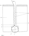
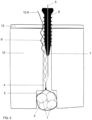
- the blockage is obtained either by pushing back and embedding the corpuscles in the bone wall, or by trapping the corpuscles. in the space between two adjacent threads, between the core of the screw and the surrounding bone, or by a mechanism combining the two effects.
- the corpuscles may be oblong and of longitudinal dimension greater than the distance of the screw thread.
- the introduction of the screw into the tunnel causes the expulsion of the corpuscular filament outside the screw body, the corpuscles actually becoming embedded in the surrounding bone tissue.
- the shape of the corpuscle may also be optimized to promote this intraosseous penetration.
- the distance between the corpuscles as well as their size are adjusted so that they fit into the space between the threads of the screw, which thus create a practically insurmountable obstacle to the sliding of the corpuscles. Indeed, they are thus trapped, above and below them by the thread of the screw and laterally, by the rigid wall of the bone tunnel.
- the two modes can be advantageously combined by the use of corpuscles whose dimensions allow both the enclave between the threads of the screw (by adjusting the intercorpuscular distance) and the protrusion into the bone tissue (by adjusting their shape and diameter) (see further: description of the corpuscles).
- the screw has a conical shape, especially near its tip, which must be as thin as possible. It is necessary that, as it progresses through the tunnel, the screw leaves enough space for the corpuscle to be able to insinuate itself between its tip and the wall of the bone tunnel, in order to embed itself there. It is easy to understand that a screw that is too massive, the end of which would occupy the entire diameter of the bone tunnel, would cause the corpuscles encountered to be pushed out of the tunnel, thus preventing any possibility of anchoring the wire in the tunnel.
- the interaction of the screw-corpuscle couple therefore requires a precise adjustment of the shape and size of the screw in relation to the shape and size of the corpuscles, but also a very precise adjustment of the size of these components in relation to the diameter of the bone tunnel, i.e. to the dimensions of the auger for digging the tunnels.
- the suspension cable must be both highly resistant to tensile forces, as rigid as possible and as small as possible to allow its insertion through bone tunnels of minimum caliber.
- Dyneema ® fiber has mechanical characteristics that meet the requirements of the proposed system particularly well. It is widely used in various fields requiring very strong ropes (water sports, parachuting, mountaineering, etc.) but it is also part of various medical applications. It is a high-density polyethylene fiber that is extremely resistant to traction (15 times stronger than steel wire) and has high rigidity (low elasticity), which corresponds exactly to the characteristics of the suspension system we are looking for. For example, a 1.5 to 2 mm rope can withstand loads of 200 to 300 kg, which constitutes a resistance limit two to three times higher than that required in the context of the invention.
- the rope according to the invention is therefore composed of an extremely strong filament of very small diameter, on which will be fixed one or more corpuscles intended to neutralize any possibility of slippage after the installation of the blocking member (screw).
- Different embodiments make it possible to respond to variations in circumstances and objectives to be achieved.
- the wire may consist of a single filament, one end of which is folded and reattached to itself (by splicing, suturing, crimping, etc.) to form a free loop for suspending a ligament loop.
- the end of the wire may terminate in a crimped needle for threading the end of the ligament to be reattached.
- the filament may be folded back on itself, thereby creating a loop capable of tying and suspending a ligament loop, each section of the wire located on either side of the loop then being able to be furnished with corpuscles.
- These corpuscles will be manufactured preferably using a biocompatible composite material (e.g. Peek, PLLA etc.) But any other solid and biocompatible material could be used (e.g. metal etc.).
- the fixation of the corpuscle on the wire must be as strong as possible because it is the tear resistance of each corpuscle multiplied by the number of corpuscles which will determine the overall tear resistance of the wire itself and therefore of the ligament graft which it suspends.
- the method of fixing the corpuscles to the wire depends closely on the type of material chosen. Any manufacturing process (chemical, physical, mechanical, etc.) can be used provided that it allows a solid fixing to the wire to be obtained.
- the shape and size characteristics of the corpuscles play a vital role in the type of blocking mechanism that occurs under the effect of the introduction of the screw.
- Its shape is generally spherical but any other shape with edges facilitating its bone penetration will be preferred if the size of the corpuscles allows it.
- the screw will have the effect of trapping the corpuscle in the concavity located between the threads of the screw, the corpuscle thus being stuck on the one hand between the wall of the thread above and below and on the other hand between the core of the screw and the surrounding bone.
- This mechanism obviously requires during manufacturing a precise adjustment between the dimensions of the screw and the length of the filament between each corpuscle.
- the two mechanisms can be combined if the corpuscles have an oval shape whose dimension along the longitudinal axis allows the enclave between two threads and the dimension along the transverse axis, perpendicular to the axis of the thread, greater than the width of the thread, causing its embedding in the bone tissue.
- the screw will be able to advance without pushing the corpuscle out of the tunnel, but on the contrary it will trap it in the space between itself (its core) and the wall of the bone tunnel.
- the semitendinosus is classically removed using a stripper.
- the tendon is prepared by wrapping it around itself to form a short closed graft of 1 to 4 strands allowing it to be suspended by means of a traction loop 2 placed at each end of the graft.
- the ribbons pass freely through each end of the graft and can therefore be introduced after the graft has been made.
- loops 2 are closed and the graft must therefore be made by passing the tendon strands through the two loops already in place on the preparation table.
- a protective sheath 3 made of textile or composite material can be added to the handle of the wire (either during manufacture or at the time of use) in order to avoid any risk of shearing of the graft by the wire.
- the tendon strands are fixed together by one or two stitches placed at each end of the graft.
- the tunnels and lodges are prepared in a classic manner using known techniques left to the surgeon's choice.
- the digging of tunnels 4 and lodges 5 is done, at the surgeon's discretion, either from the inside out using in-out sights or using flexible pins and drill bits (which allow the surgeon to choose the insertion site that seems optimal), or from the outside in using out-in sights.
- the placement of guide pin 6 is done from the outside in using the appropriate sights and the lodge will be made retrograde using specific tools available on the market.
- the graft is introduced into the knee via the antero-internal approach.
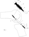
- the wire 10 suspending the femoral segment of the graft is passed into the femoral tunnel 2 through its intra-articular orifice and is recovered on the external face of the femur through a 2 or 3 mm cutaneous orifice, through which the femoral guide pin also emerges. Traction on this wire 10 causes the graft 1 to penetrate into the femoral pocket 5 until it comes to rest on the bottom of this pocket.
- a similar maneuver is performed on the tibia to position the tibial insertion segment of the graft 1.
- this maneuver is very easy to perform, without having to surgically approach the external surface of the bone concerned and therefore without having to create a cutaneous approach (apart from the 2 or 3 mm necessary for the passage of the wire 10 and the guide pin 6).
- the present invention makes it possible to avoid the risks of screwing defects specific to the TLS system (excess or insufficient introduction of the screw or divergence of the screw relative to the axis of the bone tunnel).
- the perforated screw 8 follows a path necessarily parallel to the wire 10 thanks to the guide pin 6 eliminating any risk of divergence.
- the screw head that automatically stops at the cortical level, the risk of excess or insufficient screwing is also completely eliminated.
- the same maneuver allows the graft to be locked to the tibia.
- the present invention describes a system particularly well adapted to the surgical reconstruction of the anterior cruciate ligament by short graft, this is in no way a choice excluding the possibility of applying the system to other situations encountered in surgery.
- the same system applies very well for example to the reconstruction of the posterior cruciate ligament, the internal and external lateral ligaments but could also be suitable for any other procedure requiring the fixation of soft, tendinous or ligamentous structures to bone structures.
- the present invention discloses a simple means of securely fixing, by means of a bone screw, perforated or not, any type of wire or cable requiring fixing in a bone structure, thus avoiding having to resort to current sophisticated devices (intra-osseous anchors, etc.) which are most often very expensive to use.
- a simple wire with corpuscles at each end could be placed parallel to it, giving it a length slightly greater than that of the "suspension wire-graft-suspension wire” complex.
- the suspensory wire and the protective wire would be fixed on either side of the graft in the same bone tunnels by means of the same screws, tibial and femoral.
- the tension first occurs within the graft itself, this being shorter but, in the event of greater movement, the tension then propagates to the protective filament, which automatically slows down or even stops the risky movement by protecting the graft against excess tension or even a risk of rupture.
Landscapes
- Health & Medical Sciences (AREA)
- Life Sciences & Earth Sciences (AREA)
- Surgery (AREA)
- Animal Behavior & Ethology (AREA)
- General Health & Medical Sciences (AREA)
- Engineering & Computer Science (AREA)
- Biomedical Technology (AREA)
- Heart & Thoracic Surgery (AREA)
- Veterinary Medicine (AREA)
- Public Health (AREA)
- Medical Informatics (AREA)
- Rheumatology (AREA)
- Molecular Biology (AREA)
- Nuclear Medicine, Radiotherapy & Molecular Imaging (AREA)
- Orthopedic Medicine & Surgery (AREA)
- Rehabilitation Therapy (AREA)
- Cardiology (AREA)
- Oral & Maxillofacial Surgery (AREA)
- Transplantation (AREA)
- Vascular Medicine (AREA)
- Surgical Instruments (AREA)
- Prostheses (AREA)
Claims (10)
- Vorrichtung zur Befestigung von Weichgewebe an einem Knochengewebe, wobei die Vorrichtung Folgendes umfasst:- einen flexiblen Draht (10), der an einem seiner Enden eine geschlossene Schlaufe zur Aufnahme des Weichgewebes bildet und mit mehreren entlang seiner Länge befestigten Körperchen (9, 9') versehen ist, wobei der Draht dazu ausgelegt ist, in einen Knochentunnel eingeführt zu werden, der eine Wand definiert,- eine kanülierte Schraube (8), die ausgelegt ist, um mit den Körperchen des Drahts (10) beim Einschrauben in den Knochentunnel (4) zusammenzuwirken, wodurch der Draht zwischen einem Gewinde der Schraube und dem Knochengewebe blockiert wird, und- einem Führungsstift (6), der ausgelegt ist, um mit der Schraube (8) zusammenzuwirken.
- Vorrichtung nach Anspruch 1, wobei die geschlossene Schlaufe zwei Zweige umfasst, die mit den Körperchen versehen sind.
- Vorrichtung nach Anspruch 1, wobei der Draht in einer gecrimpten Nadel (11) endet, die es ermöglicht, eine Bindung eines Endes eines auf den Knochen wieder zu befestigenden Bandes vorzunehmen.
- Vorrichtung nach einem der vorhergehenden Ansprüche, wobei die Schraube ein distales verjüngtes Segment aufweist, das ausgelegt ist, um einen Raum (7) zu schaffen, der ausreicht, um das Eindringen eines Körperchens zwischen sich und der Tunnelwand zu ermöglichen.
- Vorrichtung nach einem der vorhergehenden Ansprüche, wobei die Schraube eine Größe aufweist, die zunimmt, während man sich einem Kopf der Schraube nähert.
- Vorrichtung nach einem der Ansprüche 1 bis 4, wobei die Schraube eine Sektion mit konstanter Größe aufweist, die jedoch so bemessen ist, dass sie das Körperchen mindestens seitlich verdrängt, um mit der Wand des Knochentunnels in Kontakt zu kommen.
- Vorrichtung nach einem der vorhergehenden Ansprüche, wobei die Abmessung der Körperchen (9) kleiner oder gleich einem Abstand zwischen zwei benachbarten Segmenten von Schraubengewinden ist oder sie länglich (9') mit Längsabmessung größer als dieser Abstand sind.
- Vorrichtung nach einem der Ansprüche 1 bis 7, wobei die Körperchen (9) kugelförmig, abgerundet oder eckförmig sind und mit Längsabmessung, die kleiner als die Schraubenteilung ist, so dass sie zwischen zwei benachbarten Segmenten des Gewindes der Schraube (8) eingeschlossen und eingeklemmt werden können, und mit Querabmessung, so dass sie in der Lage sind, mit der Wand des Knochentunnels bündig zu sein oder in diese einzupassen.
- Vorrichtung nach einem der vorhergehenden Ansprüche, wobei ein zusätzlicher Draht vorgesehen ist, der dazu bestimmt ist, parallel zum Transplantat angebracht zu werden, der jedoch etwas länger als der Transplantat-Befestigungs-Komplex ist und mittels der gleichen Schrauben und im gleichen Knochentunnel wie für die Befestigung des Transplantats befestigt ist.
- Vorrichtung nach einem der Ansprüche 1 bis 9, wobei die Körperchen einzeln oder in Kombination um 2 bis 20 mm voneinander beabstandet sind, eine Querabmessung von 1 bis 3 mm und eine Längsabmessung von 2 bis 8 mm variieren, ein Drahtdurchmesser von 0,5 bis 3 mm variiert und ein Schraubendurchmesser von 3 bis 8 mm variiert.
Applications Claiming Priority (3)
| Application Number | Priority Date | Filing Date | Title |
|---|---|---|---|
| BE201505539 | 2015-08-26 | ||
| EP2016050929 | 2016-01-18 | ||
| PCT/EP2016/070265 WO2017032901A1 (fr) | 2015-08-26 | 2016-08-26 | Systeme de fixation intra-osseuse d'un filin souple destine a l'ancrage osseux de tissus ligamentaires |
Publications (2)
| Publication Number | Publication Date |
|---|---|
| EP3340927A1 EP3340927A1 (de) | 2018-07-04 |
| EP3340927B1 true EP3340927B1 (de) | 2024-10-09 |
Family
ID=56896514
Family Applications (1)
| Application Number | Title | Priority Date | Filing Date |
|---|---|---|---|
| EP16763464.1A Active EP3340927B1 (de) | 2015-08-26 | 2016-08-26 | System zur intraossären befestigung eines flexiblen drahts zur verankerung von bändergewebe an knochen |
Country Status (6)
| Country | Link |
|---|---|
| US (1) | US20190209288A1 (de) |
| EP (1) | EP3340927B1 (de) |
| JP (1) | JP6636137B2 (de) |
| AU (1) | AU2016310571B2 (de) |
| ES (1) | ES2993737T3 (de) |
| WO (1) | WO2017032901A1 (de) |
Families Citing this family (2)
| Publication number | Priority date | Publication date | Assignee | Title |
|---|---|---|---|---|
| US11903813B2 (en) | 2019-04-15 | 2024-02-20 | Kevin L. Harreld | Intraosseous screw with cortical window and system and method for associating soft tissue with bone |
| CN115607251A (zh) * | 2022-07-09 | 2023-01-17 | 北京天星博迈迪医疗器械有限公司 | 防松脱式接骨螺钉、免打结接骨系统 |
Citations (1)
| Publication number | Priority date | Publication date | Assignee | Title |
|---|---|---|---|---|
| US4950270A (en) * | 1989-02-03 | 1990-08-21 | Boehringer Mannheim Corporation | Cannulated self-tapping bone screw |
Family Cites Families (11)
| Publication number | Priority date | Publication date | Assignee | Title |
|---|---|---|---|---|
| US5671695A (en) * | 1994-07-28 | 1997-09-30 | Depuy Inc. | Replacement ligament graft passer and method |
| US5756127A (en) * | 1996-10-29 | 1998-05-26 | Wright Medical Technology, Inc. | Implantable bioresorbable string of calcium sulfate beads |
| ATE318122T1 (de) * | 1999-11-15 | 2006-03-15 | Arthrex Inc | Verjüngende bioabsorbierende interferenzschraube zur ostealen befestigung von bändern |
| DE20101791U1 (de) * | 2001-02-02 | 2001-05-03 | Aesculap AG & Co. KG, 78532 Tuttlingen | Implantat |
| FR2847456B1 (fr) * | 2002-11-21 | 2005-01-28 | Michel Collette | Vis de fixation d'un greffon ligamentaire |
| US20050278023A1 (en) * | 2004-06-10 | 2005-12-15 | Zwirkoski Paul A | Method and apparatus for filling a cavity |
| EP1968418B1 (de) * | 2005-12-09 | 2015-04-15 | Spinal Ventures, Inc. | Reparatur von nichtweichteilen |
| US20090292321A1 (en) | 2006-06-23 | 2009-11-26 | Michel Collette | Bone anchoring device |
| US20090018655A1 (en) * | 2007-07-13 | 2009-01-15 | John Brunelle | Composite Implant for Surgical Repair |
| US8814904B2 (en) * | 2010-10-26 | 2014-08-26 | Ziptek LLC. | Surgical suture system |
| WO2013139985A2 (fr) | 2012-03-23 | 2013-09-26 | Brevexco Sprl | Systeme de fixation d'une greffe ligamentaire |
-
2016
- 2016-08-26 EP EP16763464.1A patent/EP3340927B1/de active Active
- 2016-08-26 US US15/754,906 patent/US20190209288A1/en not_active Abandoned
- 2016-08-26 AU AU2016310571A patent/AU2016310571B2/en active Active
- 2016-08-26 WO PCT/EP2016/070265 patent/WO2017032901A1/fr not_active Ceased
- 2016-08-26 JP JP2018510763A patent/JP6636137B2/ja active Active
- 2016-08-26 ES ES16763464T patent/ES2993737T3/es active Active
Patent Citations (1)
| Publication number | Priority date | Publication date | Assignee | Title |
|---|---|---|---|---|
| US4950270A (en) * | 1989-02-03 | 1990-08-21 | Boehringer Mannheim Corporation | Cannulated self-tapping bone screw |
Also Published As
| Publication number | Publication date |
|---|---|
| ES2993737T3 (en) | 2025-01-08 |
| JP2019500912A (ja) | 2019-01-17 |
| US20190209288A1 (en) | 2019-07-11 |
| JP6636137B2 (ja) | 2020-01-29 |
| AU2016310571A1 (en) | 2018-03-29 |
| AU2016310571B2 (en) | 2019-07-04 |
| EP3340927A1 (de) | 2018-07-04 |
| WO2017032901A1 (fr) | 2017-03-02 |
Similar Documents
| Publication | Publication Date | Title |
|---|---|---|
| WO2004045465A1 (fr) | Vis d'ancrage d'une bandelette relais ou d'un fil de suture | |
| EP2043555A1 (de) | Knochenverankerungsvorrichtung | |
| EP0423297B1 (de) | Einrichtung zur verstärkung und unterstützung einer schultergelenkskapsel | |
| EP0861633B1 (de) | Knochenankervorrichtung sowie Setzgerät | |
| WO2013139985A2 (fr) | Systeme de fixation d'une greffe ligamentaire | |
| FR2490483A1 (fr) | Implant chirurgical sous forme d'un clou et un necessaire pour implant chirurgical, comprenant un cordon flexible, un clou et un element d'ancrage | |
| EP0886502A1 (de) | Sehnendurchführvorrichtung | |
| FR2774580A1 (fr) | Dispositif chirurgical d'ancrage osseux | |
| FR2977140A1 (fr) | Implant inter-epineux et instrument d’implantation | |
| EP4103066A1 (de) | Verankerungsvorrichtung für weichgewebereparatur | |
| FR2623083A1 (fr) | Prothese ligamentaire ou tendineuse et procede de fabrication de ladite prothese | |
| FR2948556A1 (fr) | Ligament prothetique pour fixation transversale et procede de confection | |
| EP3323386B1 (de) | Implantierbare befestigungsvorrichtung für die verbindung eines transplantats mit mindestens einem knochen eines gelenks | |
| WO2017032901A1 (fr) | Systeme de fixation intra-osseuse d'un filin souple destine a l'ancrage osseux de tissus ligamentaires | |
| WO2022171801A1 (fr) | Dispositif de blocage de fils de suture | |
| GB2495487A (en) | Surgical aglet for attachment to a graft material | |
| WO2009112683A2 (fr) | Fil chirurgical pour la reconstruction dans le domaine de la chirurgie et de la médecine esthétique | |
| WO2024121245A1 (fr) | Instrument ancillaire pour chirurgie de la disjonction acromio-claviculaire | |
| FR2904527A1 (fr) | Necessaire chirurgical de ligamentoplastie | |
| EP1683501A1 (de) | Osteosynthesevorrichtung für ein Schultergelenk | |
| FR2867380A1 (fr) | Dispositif universel de reparation de ligaments rompus | |
| FR3123191A1 (fr) | Implant d’ancrage et ensemble chirurgical pour ligamentoplastie | |
| KR20150058776A (ko) | 후방십자인대 재건술용 이식건 고정기구 | |
| FR2841765A1 (fr) | Vis d'interference bioresorbable |
Legal Events
| Date | Code | Title | Description |
|---|---|---|---|
| STAA | Information on the status of an ep patent application or granted ep patent |
Free format text: STATUS: THE INTERNATIONAL PUBLICATION HAS BEEN MADE |
|
| PUAI | Public reference made under article 153(3) epc to a published international application that has entered the european phase |
Free format text: ORIGINAL CODE: 0009012 |
|
| STAA | Information on the status of an ep patent application or granted ep patent |
Free format text: STATUS: REQUEST FOR EXAMINATION WAS MADE |
|
| 17P | Request for examination filed |
Effective date: 20180226 |
|
| AK | Designated contracting states |
Kind code of ref document: A1 Designated state(s): AL AT BE BG CH CY CZ DE DK EE ES FI FR GB GR HR HU IE IS IT LI LT LU LV MC MK MT NL NO PL PT RO RS SE SI SK SM TR |
|
| AX | Request for extension of the european patent |
Extension state: BA ME |
|
| DAV | Request for validation of the european patent (deleted) | ||
| DAX | Request for extension of the european patent (deleted) | ||
| STAA | Information on the status of an ep patent application or granted ep patent |
Free format text: STATUS: EXAMINATION IS IN PROGRESS |
|
| 17Q | First examination report despatched |
Effective date: 20210730 |
|
| P01 | Opt-out of the competence of the unified patent court (upc) registered |
Effective date: 20230630 |
|
| GRAP | Despatch of communication of intention to grant a patent |
Free format text: ORIGINAL CODE: EPIDOSNIGR1 |
|
| STAA | Information on the status of an ep patent application or granted ep patent |
Free format text: STATUS: GRANT OF PATENT IS INTENDED |
|
| INTG | Intention to grant announced |
Effective date: 20240621 |
|
| RIC1 | Information provided on ipc code assigned before grant |
Ipc: A61B 17/06 20060101ALI20240607BHEP Ipc: A61B 17/04 20060101ALI20240607BHEP Ipc: A61F 2/08 20060101AFI20240607BHEP |
|
| GRAS | Grant fee paid |
Free format text: ORIGINAL CODE: EPIDOSNIGR3 |
|
| GRAA | (expected) grant |
Free format text: ORIGINAL CODE: 0009210 |
|
| STAA | Information on the status of an ep patent application or granted ep patent |
Free format text: STATUS: THE PATENT HAS BEEN GRANTED |
|
| AK | Designated contracting states |
Kind code of ref document: B1 Designated state(s): AL AT BE BG CH CY CZ DE DK EE ES FI FR GB GR HR HU IE IS IT LI LT LU LV MC MK MT NL NO PL PT RO RS SE SI SK SM TR |
|
| REG | Reference to a national code |
Ref country code: CH Ref legal event code: EP |
|
| REG | Reference to a national code |
Ref country code: DE Ref legal event code: R096 Ref document number: 602016089756 Country of ref document: DE |
|
| REG | Reference to a national code |
Ref country code: IE Ref legal event code: FG4D Free format text: LANGUAGE OF EP DOCUMENT: FRENCH |
|
| REG | Reference to a national code |
Ref country code: ES Ref legal event code: FG2A Ref document number: 2993737 Country of ref document: ES Kind code of ref document: T3 Effective date: 20250108 |
|
| REG | Reference to a national code |
Ref country code: LT Ref legal event code: MG9D |
|
| REG | Reference to a national code |
Ref country code: NL Ref legal event code: MP Effective date: 20241009 |
|
| REG | Reference to a national code |
Ref country code: AT Ref legal event code: MK05 Ref document number: 1729752 Country of ref document: AT Kind code of ref document: T Effective date: 20241009 |
|
| PG25 | Lapsed in a contracting state [announced via postgrant information from national office to epo] |
Ref country code: NL Free format text: LAPSE BECAUSE OF FAILURE TO SUBMIT A TRANSLATION OF THE DESCRIPTION OR TO PAY THE FEE WITHIN THE PRESCRIBED TIME-LIMIT Effective date: 20241009 |
|
| PG25 | Lapsed in a contracting state [announced via postgrant information from national office to epo] |
Ref country code: NL Free format text: LAPSE BECAUSE OF FAILURE TO SUBMIT A TRANSLATION OF THE DESCRIPTION OR TO PAY THE FEE WITHIN THE PRESCRIBED TIME-LIMIT Effective date: 20241009 |
|
| PG25 | Lapsed in a contracting state [announced via postgrant information from national office to epo] |
Ref country code: HR Free format text: LAPSE BECAUSE OF FAILURE TO SUBMIT A TRANSLATION OF THE DESCRIPTION OR TO PAY THE FEE WITHIN THE PRESCRIBED TIME-LIMIT Effective date: 20241009 Ref country code: IS Free format text: LAPSE BECAUSE OF FAILURE TO SUBMIT A TRANSLATION OF THE DESCRIPTION OR TO PAY THE FEE WITHIN THE PRESCRIBED TIME-LIMIT Effective date: 20250209 Ref country code: PT Free format text: LAPSE BECAUSE OF FAILURE TO SUBMIT A TRANSLATION OF THE DESCRIPTION OR TO PAY THE FEE WITHIN THE PRESCRIBED TIME-LIMIT Effective date: 20250210 |
|
| PG25 | Lapsed in a contracting state [announced via postgrant information from national office to epo] |
Ref country code: FI Free format text: LAPSE BECAUSE OF FAILURE TO SUBMIT A TRANSLATION OF THE DESCRIPTION OR TO PAY THE FEE WITHIN THE PRESCRIBED TIME-LIMIT Effective date: 20241009 |
|
| PG25 | Lapsed in a contracting state [announced via postgrant information from national office to epo] |
Ref country code: BG Free format text: LAPSE BECAUSE OF FAILURE TO SUBMIT A TRANSLATION OF THE DESCRIPTION OR TO PAY THE FEE WITHIN THE PRESCRIBED TIME-LIMIT Effective date: 20241009 |
|
| PG25 | Lapsed in a contracting state [announced via postgrant information from national office to epo] |
Ref country code: NO Free format text: LAPSE BECAUSE OF FAILURE TO SUBMIT A TRANSLATION OF THE DESCRIPTION OR TO PAY THE FEE WITHIN THE PRESCRIBED TIME-LIMIT Effective date: 20250109 |
|
| PG25 | Lapsed in a contracting state [announced via postgrant information from national office to epo] |
Ref country code: LV Free format text: LAPSE BECAUSE OF FAILURE TO SUBMIT A TRANSLATION OF THE DESCRIPTION OR TO PAY THE FEE WITHIN THE PRESCRIBED TIME-LIMIT Effective date: 20241009 Ref country code: GR Free format text: LAPSE BECAUSE OF FAILURE TO SUBMIT A TRANSLATION OF THE DESCRIPTION OR TO PAY THE FEE WITHIN THE PRESCRIBED TIME-LIMIT Effective date: 20250110 Ref country code: AT Free format text: LAPSE BECAUSE OF FAILURE TO SUBMIT A TRANSLATION OF THE DESCRIPTION OR TO PAY THE FEE WITHIN THE PRESCRIBED TIME-LIMIT Effective date: 20241009 |
|
| PG25 | Lapsed in a contracting state [announced via postgrant information from national office to epo] |
Ref country code: PL Free format text: LAPSE BECAUSE OF FAILURE TO SUBMIT A TRANSLATION OF THE DESCRIPTION OR TO PAY THE FEE WITHIN THE PRESCRIBED TIME-LIMIT Effective date: 20241009 |
|
| PG25 | Lapsed in a contracting state [announced via postgrant information from national office to epo] |
Ref country code: RS Free format text: LAPSE BECAUSE OF FAILURE TO SUBMIT A TRANSLATION OF THE DESCRIPTION OR TO PAY THE FEE WITHIN THE PRESCRIBED TIME-LIMIT Effective date: 20250109 |
|
| PG25 | Lapsed in a contracting state [announced via postgrant information from national office to epo] |
Ref country code: SM Free format text: LAPSE BECAUSE OF FAILURE TO SUBMIT A TRANSLATION OF THE DESCRIPTION OR TO PAY THE FEE WITHIN THE PRESCRIBED TIME-LIMIT Effective date: 20241009 |
|
| PG25 | Lapsed in a contracting state [announced via postgrant information from national office to epo] |
Ref country code: DK Free format text: LAPSE BECAUSE OF FAILURE TO SUBMIT A TRANSLATION OF THE DESCRIPTION OR TO PAY THE FEE WITHIN THE PRESCRIBED TIME-LIMIT Effective date: 20241009 |
|
| REG | Reference to a national code |
Ref country code: DE Ref legal event code: R097 Ref document number: 602016089756 Country of ref document: DE |
|
| PG25 | Lapsed in a contracting state [announced via postgrant information from national office to epo] |
Ref country code: EE Free format text: LAPSE BECAUSE OF FAILURE TO SUBMIT A TRANSLATION OF THE DESCRIPTION OR TO PAY THE FEE WITHIN THE PRESCRIBED TIME-LIMIT Effective date: 20241009 |
|
| PG25 | Lapsed in a contracting state [announced via postgrant information from national office to epo] |
Ref country code: RO Free format text: LAPSE BECAUSE OF FAILURE TO SUBMIT A TRANSLATION OF THE DESCRIPTION OR TO PAY THE FEE WITHIN THE PRESCRIBED TIME-LIMIT Effective date: 20241009 |
|
| PG25 | Lapsed in a contracting state [announced via postgrant information from national office to epo] |
Ref country code: SK Free format text: LAPSE BECAUSE OF FAILURE TO SUBMIT A TRANSLATION OF THE DESCRIPTION OR TO PAY THE FEE WITHIN THE PRESCRIBED TIME-LIMIT Effective date: 20241009 |
|
| PG25 | Lapsed in a contracting state [announced via postgrant information from national office to epo] |
Ref country code: CZ Free format text: LAPSE BECAUSE OF FAILURE TO SUBMIT A TRANSLATION OF THE DESCRIPTION OR TO PAY THE FEE WITHIN THE PRESCRIBED TIME-LIMIT Effective date: 20241009 |
|
| PLBE | No opposition filed within time limit |
Free format text: ORIGINAL CODE: 0009261 |
|
| STAA | Information on the status of an ep patent application or granted ep patent |
Free format text: STATUS: NO OPPOSITION FILED WITHIN TIME LIMIT |
|
| PG25 | Lapsed in a contracting state [announced via postgrant information from national office to epo] |
Ref country code: SE Free format text: LAPSE BECAUSE OF FAILURE TO SUBMIT A TRANSLATION OF THE DESCRIPTION OR TO PAY THE FEE WITHIN THE PRESCRIBED TIME-LIMIT Effective date: 20241009 |
|
| 26N | No opposition filed |
Effective date: 20250710 |
|
| PGFP | Annual fee paid to national office [announced via postgrant information from national office to epo] |
Ref country code: ES Payment date: 20250916 Year of fee payment: 10 |
|
| PGFP | Annual fee paid to national office [announced via postgrant information from national office to epo] |
Ref country code: DE Payment date: 20250827 Year of fee payment: 10 |
|
| PGFP | Annual fee paid to national office [announced via postgrant information from national office to epo] |
Ref country code: IT Payment date: 20250806 Year of fee payment: 10 |
|
| PGFP | Annual fee paid to national office [announced via postgrant information from national office to epo] |
Ref country code: GB Payment date: 20250826 Year of fee payment: 10 |
|
| PGFP | Annual fee paid to national office [announced via postgrant information from national office to epo] |
Ref country code: FR Payment date: 20250825 Year of fee payment: 10 |
|
| PGFP | Annual fee paid to national office [announced via postgrant information from national office to epo] |
Ref country code: CH Payment date: 20250901 Year of fee payment: 10 |
|
| PG25 | Lapsed in a contracting state [announced via postgrant information from national office to epo] |
Ref country code: MC Free format text: LAPSE BECAUSE OF FAILURE TO SUBMIT A TRANSLATION OF THE DESCRIPTION OR TO PAY THE FEE WITHIN THE PRESCRIBED TIME-LIMIT Effective date: 20241009 |
|
| PG25 | Lapsed in a contracting state [announced via postgrant information from national office to epo] |
Ref country code: LU Free format text: LAPSE BECAUSE OF NON-PAYMENT OF DUE FEES Effective date: 20250826 |
|
| REG | Reference to a national code |
Ref country code: BE Ref legal event code: MM Effective date: 20250831 |
|
| PG25 | Lapsed in a contracting state [announced via postgrant information from national office to epo] |
Ref country code: LT Free format text: LAPSE BECAUSE OF FAILURE TO SUBMIT A TRANSLATION OF THE DESCRIPTION OR TO PAY THE FEE WITHIN THE PRESCRIBED TIME-LIMIT Effective date: 20241009 |
|
| PG25 | Lapsed in a contracting state [announced via postgrant information from national office to epo] |
Ref country code: IE Free format text: LAPSE BECAUSE OF NON-PAYMENT OF DUE FEES Effective date: 20250826 Ref country code: BE Free format text: LAPSE BECAUSE OF NON-PAYMENT OF DUE FEES Effective date: 20250831 |