EP3340588A1 - Bracket assembly, camera module, and mobile terminal - Google Patents
Bracket assembly, camera module, and mobile terminal Download PDFInfo
- Publication number
- EP3340588A1 EP3340588A1 EP17209018.5A EP17209018A EP3340588A1 EP 3340588 A1 EP3340588 A1 EP 3340588A1 EP 17209018 A EP17209018 A EP 17209018A EP 3340588 A1 EP3340588 A1 EP 3340588A1
- Authority
- EP
- European Patent Office
- Prior art keywords
- metal bracket
- bracket
- pressing portion
- bracket assembly
- metal
- Prior art date
- Legal status (The legal status is an assumption and is not a legal conclusion. Google has not performed a legal analysis and makes no representation as to the accuracy of the status listed.)
- Granted
Links
- 229910052751 metal Inorganic materials 0.000 claims abstract description 91
- 239000002184 metal Substances 0.000 claims abstract description 91
- 238000003384 imaging method Methods 0.000 claims description 20
- 230000003287 optical effect Effects 0.000 claims description 4
- 230000009977 dual effect Effects 0.000 claims 1
- 238000004891 communication Methods 0.000 description 11
- 230000003247 decreasing effect Effects 0.000 description 4
- 239000000463 material Substances 0.000 description 3
- RYGMFSIKBFXOCR-UHFFFAOYSA-N Copper Chemical compound [Cu] RYGMFSIKBFXOCR-UHFFFAOYSA-N 0.000 description 2
- XEEYBQQBJWHFJM-UHFFFAOYSA-N Iron Chemical compound [Fe] XEEYBQQBJWHFJM-UHFFFAOYSA-N 0.000 description 2
- 239000000956 alloy Substances 0.000 description 2
- 238000005452 bending Methods 0.000 description 2
- 229910052802 copper Inorganic materials 0.000 description 2
- 239000010949 copper Substances 0.000 description 2
- 230000005611 electricity Effects 0.000 description 2
- 238000009434 installation Methods 0.000 description 2
- 238000003801 milling Methods 0.000 description 2
- 230000003068 static effect Effects 0.000 description 2
- 229910000838 Al alloy Inorganic materials 0.000 description 1
- BQCADISMDOOEFD-UHFFFAOYSA-N Silver Chemical compound [Ag] BQCADISMDOOEFD-UHFFFAOYSA-N 0.000 description 1
- 230000002452 interceptive effect Effects 0.000 description 1
- 229910052742 iron Inorganic materials 0.000 description 1
- 229910001092 metal group alloy Inorganic materials 0.000 description 1
- 238000000465 moulding Methods 0.000 description 1
- 239000002994 raw material Substances 0.000 description 1
- 238000007493 shaping process Methods 0.000 description 1
- 229910052709 silver Inorganic materials 0.000 description 1
- 239000004332 silver Substances 0.000 description 1
- 230000006641 stabilisation Effects 0.000 description 1
- 238000011105 stabilization Methods 0.000 description 1
Images


Classifications
-
- H—ELECTRICITY
- H04—ELECTRIC COMMUNICATION TECHNIQUE
- H04M—TELEPHONIC COMMUNICATION
- H04M1/00—Substation equipment, e.g. for use by subscribers
- H04M1/02—Constructional features of telephone sets
- H04M1/0202—Portable telephone sets, e.g. cordless phones, mobile phones or bar type handsets
- H04M1/026—Details of the structure or mounting of specific components
- H04M1/0272—Details of the structure or mounting of specific components for a projector or beamer module assembly
-
- H—ELECTRICITY
- H04—ELECTRIC COMMUNICATION TECHNIQUE
- H04M—TELEPHONIC COMMUNICATION
- H04M1/00—Substation equipment, e.g. for use by subscribers
- H04M1/02—Constructional features of telephone sets
- H04M1/0202—Portable telephone sets, e.g. cordless phones, mobile phones or bar type handsets
- H04M1/026—Details of the structure or mounting of specific components
- H04M1/0264—Details of the structure or mounting of specific components for a camera module assembly
-
- H—ELECTRICITY
- H04—ELECTRIC COMMUNICATION TECHNIQUE
- H04M—TELEPHONIC COMMUNICATION
- H04M1/00—Substation equipment, e.g. for use by subscribers
- H04M1/02—Constructional features of telephone sets
- H04M1/0202—Portable telephone sets, e.g. cordless phones, mobile phones or bar type handsets
- H04M1/026—Details of the structure or mounting of specific components
-
- H—ELECTRICITY
- H04—ELECTRIC COMMUNICATION TECHNIQUE
- H04N—PICTORIAL COMMUNICATION, e.g. TELEVISION
- H04N23/00—Cameras or camera modules comprising electronic image sensors; Control thereof
- H04N23/57—Mechanical or electrical details of cameras or camera modules specially adapted for being embedded in other devices
-
- H—ELECTRICITY
- H04—ELECTRIC COMMUNICATION TECHNIQUE
- H04N—PICTORIAL COMMUNICATION, e.g. TELEVISION
- H04N23/00—Cameras or camera modules comprising electronic image sensors; Control thereof
- H04N23/50—Constructional details
- H04N23/51—Housings
-
- H—ELECTRICITY
- H04—ELECTRIC COMMUNICATION TECHNIQUE
- H04N—PICTORIAL COMMUNICATION, e.g. TELEVISION
- H04N23/00—Cameras or camera modules comprising electronic image sensors; Control thereof
- H04N23/90—Arrangement of cameras or camera modules, e.g. multiple cameras in TV studios or sports stadiums
Definitions
- the present disclosure relates to the field of mobile device, and particularly relates to a bracket assembly, a camera module, and a mobile terminal.
- the electronic component within mobile phones such as camera device
- a bracket Considering the rigid requirement, the exact requirement of size, and installation requirement, the material of the bracket often adopts metal to stabilize the electronic component.
- the metal is conductive, thus metallic bracket is easily interfered with the electromagnetic signal generated by the communication element inside the mobile phone. Therefore, the communication performance of the communication elements is decreased.
- the mobile terminal may be a mobile phone, a tablet computer, a notebook computer, or the like.
- the bracket assembly and the camera module may be used on the mobile terminal.
- the bracket assembly is assembled in the mobile terminal.
- a communication element can be located in the mobile terminal, and configured to receive or transmit a signal.
- a bracket assembly 1000 comprises a metal bracket 10 and a spring module 20.
- the bracket assembly 1000 can be located on a main plate 30, and the main plate 30 can be fixed to a middle frame 40. Thus the bracket assembly 1000 can be fixed between the main plate 30 and the middle frame 40.
- the metal bracket 10 can be embedded in the middle frame 40, and the spring module 20 can fix the metal bracket 10 to the main plate 30.
- the metal bracket 10 is configured to support an electronic component in a mobile terminal.
- the electronic component can be a dual-camera component.
- the spring module 20 comprises a pressing portion 201, an elastic portion 202, and a fixing portion 204.
- the pressing portion 201 can extend along the fixing portion 204.
- the elastic portion 202 connects the pressing portion 201, and the pressing portion 201 and the elastic portion 202 can be an integrated structure.
- the elastic portion 202 can be a bent structure, and the elastic portion 202 bends toward a direction away from the fixing portion.
- the fixing portion 204 can be fixed to the main plate 30 and connected to a ground electrode of the main plate 30.
- the elastic portion 202 connects the pressing portion 201 and the fixing portion 204, and provides a restoring force to the pressing portion 201.
- the pressing portion 201 can be in close contact with the metal bracket 10, and then the metal bracket 10 can be grounded through the spring module 20.
- the fixing portion 204 is fixed to the main plate 30 and connected to the ground through the main plate 30.
- the pressing portion 201 can be closely sandwiched between the metal bracket 10 and the main plate 30, and the metal bracket 10 is grounded through the main plate 30 without changing the structure of the metal bracket 10.
- the fixing portion 204 includes a base plate 204a and a bent end 204b.
- the bent end 204b extends from the edges of the base plate 204a.
- the bent end 204b can be perpendicular with the base plate 204a.
- the bent end 204b can be fixed to the main plate 30.
- the pressing portion 201, the elastic portion 202, and the fixing portion 204 are integrally formed by bending a metal and / or a metal alloy material.
- the fixing portion 204, the pressing portion 201, and the elastic portion 202 are integrally molded.
- the spring module 20 further comprises a limit portion 203.
- the limit portion 203 can be located at one end of the base plate 204a.
- a limit end 201a of the pressing portion 201 is accommodated in the limit portion 203, and the elastic portion 202 is formed on a free end opposite to the limit end 201a of the pressing portion 201.
- the limit portion can be formed by bending one end of the base plate 204a toward a direction away from the pressing portion 201.
- the limit portion 203 is configured to limit the position of the pressing portion 201 and prevent the pressing portion 201 from excessive deformation without pressure.
- the elastic portion 202 can provide the restoring force to the pressing portion 201, so that the pressing portion 201 is in close contact with the metal bracket 10.
- the limit portion 203 restricts the moving range of the limit end 201a and prevents the pressing portion 201 from becoming excessively large.
- the pressing portion 201 comprises a contact point 201b.
- the contact point 201b protrudes out of an outer surface of the pressing portion 201, and configured to enhance the pressure between the metal bracket 10 and the main plate 30.
- the contact point 201b can be elastic with two layered structures.
- the metal bracket 10 comprises a plurality of sidewalls 102.
- the plurality of sidewalls 102 are connected end to end to form an accommodating space 11 for accommodating the electronic component.
- the metal bracket 10 accommodates the electronic component to facilitate the installation and stabilization of the electronic component.
- the electronic component may be a camera module, a speaker, a fingerprint module, a connector, or the like.
- the metal bracket 10 can be rectangular.
- the metal bracket 10 can be made of aluminum alloy material, silver material, or iron material.
- the metal bracket 10 is formed by shaping the metal block by an automatic numerical control milling process. That is, the molding dimensions of the sidewall 102 are formed by numerical control milling.
- the metal bracket 10 can also be effectively fixed to an external element (not shown), thus the fixing position of the metal bracket 10 is accurate and the positioning of the metal bracket 10 is facilitated. Therefore, the mounting position of the electronic component can be accurately improved.
- the accommodating space 11 can accommodate a plurality of electronic components, at the same time, and the plurality of electronic components can be mounted at the same time.
- the metal bracket 10 can fix the plurality of electronic components to save space.
- a plurality of spring modules 1000 can be applied in the mobile terminal.
- the plurality of the spring modules 20 are distributed around the plurality of sidewalls 102.
- each of the plurality of sidewalls 102 has one spring module 20 located on an outside of the sidewall 102 opposite to the accommodating space 11.
- the pressing portion 201 resiliently abuts against a wall surface of the sidewall 102 away from the accommodating space 11.
- the restoring force applied by the elastic portion 202 to the pressing portion 201 causes the pressing portion 201 to come into close contact with the wall surface, to ensure that the pressing portion 201 and the metal bracket 10 can be tightly in contacted with each other.
- the spring module 20 and the metal bracket 10 can be prevented from detachment, and the structural stability of the mobile terminal can be enhanced.
- the pressing portion 201 elastically contacts the wall surface of the metal bracket 10, thus the attachment and detachment of the metal bracket 10 can be facilitated.
- the metal bracket 10 can be pulled out along the direction perpendicular with the sidewall 102 pressed by the pressing portion 201.
- the metal bracket 10 can be assembled by pressing the pressing portion and inserting the metal bracket 10. Therefore, the difficulty of assembling and disassembling the metal bracket 10 is reduced.
- the spring module 20 can be mounted between each sidewall 102 and the main plate 30.
- the plurality of spring modules 20 can surround the metal bracket 10, and the plurality of pressing portions 201 are either simultaneously in contact with the different positions of the wall surfaces of the metal brackets 10, or the different wall surfaces.
- the entire metal bracket 10 is grounded, and the overall potential can be decreased. Therefore, the interference to the electromagnetic signals of the communication elements can be reduced, and the user experience can be improved. Because the plurality of contact points 201b on the plurality of pressing portions are spaced from each other, and in contact with the sidewalls 102, thus the metal bracket 10 can be grounded by the plurality of spring modules 20.
- the number of sidewalls 102 can be even, and the plurality of contact points 201b are symmetrically distributed on each two opposite sidewalls 102.
- the symmetrical contact points 201b uniformly ground the respective sidewalls 102 of the metal bracket 10. Therefore, the overall potential of the metal support 10 can be uniformly reduced, the interference to the electromagnetic signal of the communication element can be dramatically reduced, and the user experience can be further improved.
- the metal bracket 10 is fixed to the middle frame 40 while the bracket assembly 1000 is applied to the mobile terminal.
- a plurality of fixing blocks 104 is located on the wall surface of the sidewall 102 away from the accommodating space 11.
- a plurality of slots 404 is defined in the middle frame 40 for accommodating the plurality of fixing blocks 104.
- the plurality of fixing block 104 of the metal bracket 10 are engaged with the plurality of slots 404, thus the metal bracket 10 is securely mounted in the middle frame 40 to improve the structural stability of the mobile terminal.
- the spring module 20 conducts the current of the metal bracket 10 to the ground electrode of the main plate 30.
- Each of the spring modules 20 can be independently and electrically connected to the ground electrode.
- the plurality of spring modules 20 can be commonly electrically connected to the ground electrode.
- the spring module 20 can reduce the overall potential of the metal support 10; on the other hand, the static electricity on the metal bracket 10 can be conducted to the ground. Thus the affection of the static electricity to the electronic component can be avoided, and the electronic component can be protected.
- the ground electrode can be exposed copper point on the main plate 30, and each of the spring modules 20 is mounted on the main plate 30 and contacts the exposed copper points on the main plate 30.
- a plurality of limit holes 304b is distributed on the main plate 30 corresponding to the plurality of bent ends 204b on the fixing portion 204.
- the plurality of bent ends 204b can be fit with the plurality of limit holes 304b, so that the spring module 20 is securely fixed to the main plate 30 to improve the structural stability of the mobile terminal.
- the plurality of bent ends 204b can be inserted into the plurality of limit holes 304b.
- a plurality of recesses 306 can be formed on the main plate 30.
- the plurality of recesses 306 can be distributed around an inner edge of the main plate 30.
- the plurality of recesses can be formed corresponding to the plurality of limit ends 201a.
- the position of the plurality of recesses 306 corresponds to the plurality of limit ends 201a on the pressing portion 201, and avoids affecting the movement of the pressing portion 201.
- the pressing portion 201 can be changed in different states under the restoring force provided by the elastic portion 202 and the pressure applied by the metal bracket 10. While the metal bracket 10 needs to be assembled, the pressing portion 201 can be pulled in a direction away from the metal bracket 10. The pressing portion 201 is pulled in the direction toward the edge of the main plate 30.
- the recesses 306 can be configured to prevent the main plate 30 from interfering with the moving range of the pressing portion 201, thus the pressing portion 201 can be freely moved.
- a camera module 100 comprises a dual-camera component 50 fixed in the bracket assembly 1000.
- the dual-camera component 50 can be embedded in the metal bracket 10.
- the spring module 20 is fixed to the main plate 30.
- the spring module 20 can be grounded through the main plate 30.
- the metal bracket 10 surrounds and supports the dual-camera component 50.
- the fixing portion 204 is fixed to the main plate 30 and connected to the ground through the main plate 30, and the pressing portion 201 is in close contact with the metal bracket 10.
- the metal bracket 10 can be electrically connected to the ground without changing the mounting structure of the metal bracket 10.
- the plurality of spring modules 20 can cause the entire metal bracket 10 to be multi-point grounded, thus the overall potential of the metal bracket 10 is reduced, and the interference to the electromagnetic signals of the communication element can be decreased.
- the dual-camera component 50 comprises a first imaging lens 501 and a second imaging lens 502 disposed side by side.
- the first imaging lens 501 and the second imaging lens 502 are mounted in the accommodating space 11 of the metal bracket 10 together.
- a first main imaging optical axis of the first imaging lens 501 and a second main imaging optical axis of the second imaging lens 502 are parallel with each other.
- the first imaging lens 501 and the second imaging lens 502 can be collaboratively operated to improve the shooting performance.
- the camera module 100 further comprises the middle frame 40 for fixing the metal bracket 10.
- the plurality of fixing blocks 104 are formed on the sidewall 102 of the metal bracket 10 away from the accommodating space 11, and the plurality of slots are formed on the middle frame 40 corresponding to the fixing block 104 , thus the metal bracket 10 is mounted in the middle frame 40.
- the fixing block 104 can be engaged with the slot 404 so that the metal bracket 10 is securely mounted in the middle frame 40 to improve the structural stability of the camera module 100.
- the camera module 100 further comprises a cover 60 which is attached to the middle frame 40.
- the main plate 30, the metal bracket 10, the spring module 20, and the dual-camera component are sandwiched between the cover 60 and the middle frame 40.
- the cover 60 is capable of covering and protecting the inside communication element. The appearance performance of the camera module 100 can also be improved.
- the cover 60 is a metal plate. Furthermore, the cover 60 has two photographing windows, and the first imaging lens 501 and the second imaging lens 502 are photographed through the two photographing windows respectively.
- the fixing portion 204 of the spring module 20 is fixed to the main plate 30 and connected to the ground through the main plate 30, and the pressing portion 201 is in close contact with the metal bracket 10.
- the metal bracket 10 is electrically connected to the ground without changing the structure of the metal bracket 10. Furthermore, the plurality of spring modules 20 cause the entire metal bracket 10 to be multi-point grounded, thus the overall potential of the metal bracket 10 is reduced, and the interference to the electromagnetic signals of the communication elements can be decreased.
- a mobile terminal 2000 comprises a shell 200 and the camera module 100 assembled in the shell 200.
- the camera module 100 comprises the dual-camera component 50 fixed in the bracket assembly 1000, and the dual-camera component 50 can be supported and fixed by the bracket assembly 1000.
- the communication element can be accommodated in the mobile terminal 2000, and the bracket assembly 1000 can prevent the communication element from interference.
Abstract
Description
- This application claims all benefits accruing under 35 U.S.C. §119 from China Patent Application No.
201611185478.1, filed on December 20, 2016 - The present disclosure relates to the field of mobile device, and particularly relates to a bracket assembly, a camera module, and a mobile terminal.
- With the development of smart phones, the electronic component within mobile phones, such as camera device, is often supported by a bracket. Considering the rigid requirement, the exact requirement of size, and installation requirement, the material of the bracket often adopts metal to stabilize the electronic component. However, the metal is conductive, thus metallic bracket is easily interfered with the electromagnetic signal generated by the communication element inside the mobile phone. Therefore, the communication performance of the communication elements is decreased.
-
-
FIG. 1 shows a schematic view of one embodiment of a bracket assembly. -
FIG. 2 shows a schematic exploded view of one embodiment of the bracket assembly. -
FIG. 3 shows a schematic view of one embodiment of a spring module. -
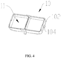
FIG. 4 shows a schematic view of one embodiment of a bracket. -
FIG. 5 shows a schematic view of one embodiment of a middle frame. -
FIG. 6 shows a schematic view of one embodiment of a main plate. -
FIG. 7 shows a schematic view of one embodiment of a camera module. -
FIG. 8 shows a schematic exploded view of the camera module. -
FIG. 9 shows a schematic view of one embodiment of a mobile terminal. - It will be appreciated that for simplicity and clarity of illustration, where appropriate, reference numerals have been repeated among the different figures to indicate corresponding or analogous elements. In addition, numerous specific details are set forth in order to provide a thorough understanding of the embodiments described herein.
- In the description of the present invention, it can be understood that, the terms "center", "upper", "down", "front", "rear", "left", "right", "vertical", "top", "bottom", "inside", "outside", "surrounding" are based on the azimuth or the positional relationship shown in the drawings. The terms are used for the purpose of facilitating the description of the invention and simplified description.
- It should be noted that the mobile terminal may be a mobile phone, a tablet computer, a notebook computer, or the like. The bracket assembly and the camera module may be used on the mobile terminal. The bracket assembly is assembled in the mobile terminal. A communication element can be located in the mobile terminal, and configured to receive or transmit a signal.
- Referring to
FIGS. 1-2 , one embodiment of abracket assembly 1000 comprises ametal bracket 10 and aspring module 20. Thebracket assembly 1000 can be located on amain plate 30, and themain plate 30 can be fixed to amiddle frame 40. Thus thebracket assembly 1000 can be fixed between themain plate 30 and themiddle frame 40. In one embodiment, themetal bracket 10 can be embedded in themiddle frame 40, and thespring module 20 can fix themetal bracket 10 to themain plate 30. Themetal bracket 10 is configured to support an electronic component in a mobile terminal. In one embodiment, the electronic component can be a dual-camera component. - Further referring to
FIG. 3 , thespring module 20 comprises apressing portion 201, anelastic portion 202, and a fixing portion 204. Thepressing portion 201 can extend along the fixing portion 204. Theelastic portion 202 connects thepressing portion 201, and thepressing portion 201 and theelastic portion 202 can be an integrated structure. Theelastic portion 202 can be a bent structure, and theelastic portion 202 bends toward a direction away from the fixing portion. The fixing portion 204 can be fixed to themain plate 30 and connected to a ground electrode of themain plate 30. Theelastic portion 202 connects thepressing portion 201 and the fixing portion 204, and provides a restoring force to thepressing portion 201. Thus thepressing portion 201 can be in close contact with themetal bracket 10, and then themetal bracket 10 can be grounded through thespring module 20. - The fixing portion 204 is fixed to the
main plate 30 and connected to the ground through themain plate 30. Thepressing portion 201 can be closely sandwiched between themetal bracket 10 and themain plate 30, and themetal bracket 10 is grounded through themain plate 30 without changing the structure of themetal bracket 10. In one embodiment, the fixing portion 204 includes a base plate 204a and abent end 204b. Thebent end 204b extends from the edges of the base plate 204a. Thebent end 204b can be perpendicular with the base plate 204a. Thebent end 204b can be fixed to themain plate 30. In one embodiment, there are a plurality ofbent ends 204b connected to the base plate 204a, and the plurality ofbent ends 204b can be bent in the same direction. - In the one embodiment, the
pressing portion 201, theelastic portion 202, and the fixing portion 204 are integrally formed by bending a metal and / or a metal alloy material. The fixing portion 204, thepressing portion 201, and theelastic portion 202 are integrally molded. Thus the processing can be simplified, and the raw material can be saved. - In one embodiment, the
spring module 20 further comprises alimit portion 203. Thelimit portion 203 can be located at one end of the base plate 204a. A limit end 201a of thepressing portion 201 is accommodated in thelimit portion 203, and theelastic portion 202 is formed on a free end opposite to the limit end 201a of thepressing portion 201. The limit portion can be formed by bending one end of the base plate 204a toward a direction away from thepressing portion 201. Thelimit portion 203 is configured to limit the position of thepressing portion 201 and prevent thepressing portion 201 from excessive deformation without pressure. Theelastic portion 202 can provide the restoring force to thepressing portion 201, so that thepressing portion 201 is in close contact with themetal bracket 10. However, before themetal bracket 10 is mounted, while thepressing portion 201 is deformed due to a large force caused by the return force, themetal bracket 10 is difficult to be mounted. Thelimit portion 203 restricts the moving range of the limit end 201a and prevents thepressing portion 201 from becoming excessively large. - In one embodiment, the
pressing portion 201 comprises acontact point 201b. Thecontact point 201b protrudes out of an outer surface of thepressing portion 201, and configured to enhance the pressure between themetal bracket 10 and themain plate 30. Furthermore, thecontact point 201b can be elastic with two layered structures. - Further referring to
FIG. 4 , in one embodiment, themetal bracket 10 comprises a plurality ofsidewalls 102. The plurality ofsidewalls 102 are connected end to end to form an accommodating space 11 for accommodating the electronic component. In one embodiment, themetal bracket 10 accommodates the electronic component to facilitate the installation and stabilization of the electronic component. The electronic component may be a camera module, a speaker, a fingerprint module, a connector, or the like. - Furthermore, the
metal bracket 10 can be rectangular. Themetal bracket 10 can be made of aluminum alloy material, silver material, or iron material. Themetal bracket 10 is formed by shaping the metal block by an automatic numerical control milling process. That is, the molding dimensions of thesidewall 102 are formed by numerical control milling. Thus the dimensional accuracy of thesidewall 102 is high, the electronic component can be effectively stabilized, and the electronic component can be fixed at a precise position. Furthermore, the position of the electronic component can be easily calibrated. At the same time, themetal bracket 10 can also be effectively fixed to an external element (not shown), thus the fixing position of themetal bracket 10 is accurate and the positioning of themetal bracket 10 is facilitated. Therefore, the mounting position of the electronic component can be accurately improved. The accommodating space 11 can accommodate a plurality of electronic components, at the same time, and the plurality of electronic components can be mounted at the same time. Thus themetal bracket 10 can fix the plurality of electronic components to save space. - In one embodiment, a plurality of
spring modules 1000 can be applied in the mobile terminal. The plurality of thespring modules 20 are distributed around the plurality ofsidewalls 102. In detail, each of the plurality ofsidewalls 102 has onespring module 20 located on an outside of thesidewall 102 opposite to the accommodating space 11. Thepressing portion 201 resiliently abuts against a wall surface of thesidewall 102 away from the accommodating space 11. The restoring force applied by theelastic portion 202 to thepressing portion 201 causes thepressing portion 201 to come into close contact with the wall surface, to ensure that thepressing portion 201 and themetal bracket 10 can be tightly in contacted with each other. Furthermore, thespring module 20 and themetal bracket 10 can be prevented from detachment, and the structural stability of the mobile terminal can be enhanced. At the same time, thepressing portion 201 elastically contacts the wall surface of themetal bracket 10, thus the attachment and detachment of themetal bracket 10 can be facilitated. Themetal bracket 10 can be pulled out along the direction perpendicular with thesidewall 102 pressed by thepressing portion 201. Themetal bracket 10 can be assembled by pressing the pressing portion and inserting themetal bracket 10. Therefore, the difficulty of assembling and disassembling themetal bracket 10 is reduced. - Furthermore, the
spring module 20 can be mounted between eachsidewall 102 and themain plate 30. The plurality ofspring modules 20 can surround themetal bracket 10, and the plurality ofpressing portions 201 are either simultaneously in contact with the different positions of the wall surfaces of themetal brackets 10, or the different wall surfaces. Thus theentire metal bracket 10 is grounded, and the overall potential can be decreased. Therefore, the interference to the electromagnetic signals of the communication elements can be reduced, and the user experience can be improved. Because the plurality of contact points 201b on the plurality of pressing portions are spaced from each other, and in contact with thesidewalls 102, thus themetal bracket 10 can be grounded by the plurality ofspring modules 20. - Furthermore, the number of
sidewalls 102 can be even, and the plurality of contact points 201b are symmetrically distributed on each twoopposite sidewalls 102. Thus the symmetrical contact points 201b uniformly ground therespective sidewalls 102 of themetal bracket 10. Therefore, the overall potential of themetal support 10 can be uniformly reduced, the interference to the electromagnetic signal of the communication element can be dramatically reduced, and the user experience can be further improved. - Further referring to
FIG. 5 , in one embodiment, themetal bracket 10 is fixed to themiddle frame 40 while thebracket assembly 1000 is applied to the mobile terminal. In detail, a plurality of fixingblocks 104 is located on the wall surface of thesidewall 102 away from the accommodating space 11. Furthermore, a plurality ofslots 404 is defined in themiddle frame 40 for accommodating the plurality of fixing blocks 104. Thus themetal bracket 10 can be firmly installed in themiddle frame 40. The plurality of fixingblock 104 of themetal bracket 10 are engaged with the plurality ofslots 404, thus themetal bracket 10 is securely mounted in themiddle frame 40 to improve the structural stability of the mobile terminal. - Further referring to
FIG. 6 , thespring module 20 conducts the current of themetal bracket 10 to the ground electrode of themain plate 30. Each of thespring modules 20 can be independently and electrically connected to the ground electrode. In one embodiment, the plurality ofspring modules 20 can be commonly electrically connected to the ground electrode. On one hand, thespring module 20 can reduce the overall potential of themetal support 10; on the other hand, the static electricity on themetal bracket 10 can be conducted to the ground. Thus the affection of the static electricity to the electronic component can be avoided, and the electronic component can be protected. The ground electrode can be exposed copper point on themain plate 30, and each of thespring modules 20 is mounted on themain plate 30 and contacts the exposed copper points on themain plate 30. - Furthermore, in one embodiment, a plurality of
limit holes 304b is distributed on themain plate 30 corresponding to the plurality of bent ends 204b on the fixing portion 204. The plurality of bent ends 204b can be fit with the plurality oflimit holes 304b, so that thespring module 20 is securely fixed to themain plate 30 to improve the structural stability of the mobile terminal. In one embodiment, the plurality of bent ends 204b can be inserted into the plurality oflimit holes 304b. - Furthermore, a plurality of
recesses 306 can be formed on themain plate 30. The plurality ofrecesses 306 can be distributed around an inner edge of themain plate 30. In one embodiment, the plurality of recesses can be formed corresponding to the plurality of limit ends 201a. The position of the plurality ofrecesses 306 corresponds to the plurality of limit ends 201a on thepressing portion 201, and avoids affecting the movement of thepressing portion 201. Thepressing portion 201 can be changed in different states under the restoring force provided by theelastic portion 202 and the pressure applied by themetal bracket 10. While themetal bracket 10 needs to be assembled, thepressing portion 201 can be pulled in a direction away from themetal bracket 10. Thepressing portion 201 is pulled in the direction toward the edge of themain plate 30. Therecesses 306 can be configured to prevent themain plate 30 from interfering with the moving range of thepressing portion 201, thus thepressing portion 201 can be freely moved. - Further referring to
FIGS. 7-8 , one embodiment of acamera module 100 comprises a dual-camera component 50 fixed in thebracket assembly 1000. The dual-camera component 50 can be embedded in themetal bracket 10. Thespring module 20 is fixed to themain plate 30. Thespring module 20 can be grounded through themain plate 30. Themetal bracket 10 surrounds and supports the dual-camera component 50. The fixing portion 204 is fixed to themain plate 30 and connected to the ground through themain plate 30, and thepressing portion 201 is in close contact with themetal bracket 10. Themetal bracket 10 can be electrically connected to the ground without changing the mounting structure of themetal bracket 10. The plurality ofspring modules 20 can cause theentire metal bracket 10 to be multi-point grounded, thus the overall potential of themetal bracket 10 is reduced, and the interference to the electromagnetic signals of the communication element can be decreased. - The dual-
camera component 50 comprises afirst imaging lens 501 and asecond imaging lens 502 disposed side by side. Thefirst imaging lens 501 and thesecond imaging lens 502 are mounted in the accommodating space 11 of themetal bracket 10 together. In one embodiment, a first main imaging optical axis of thefirst imaging lens 501 and a second main imaging optical axis of thesecond imaging lens 502 are parallel with each other. Thus thefirst imaging lens 501 and thesecond imaging lens 502 can be collaboratively operated to improve the shooting performance. - In one embodiment, the
camera module 100 further comprises themiddle frame 40 for fixing themetal bracket 10. The plurality of fixingblocks 104 are formed on thesidewall 102 of themetal bracket 10 away from the accommodating space 11, and the plurality of slots are formed on themiddle frame 40 corresponding to the fixingblock 104 , thus themetal bracket 10 is mounted in themiddle frame 40. The fixingblock 104 can be engaged with theslot 404 so that themetal bracket 10 is securely mounted in themiddle frame 40 to improve the structural stability of thecamera module 100. - In one embodiment, the
camera module 100 further comprises acover 60 which is attached to themiddle frame 40. Themain plate 30, themetal bracket 10, thespring module 20, and the dual-camera component are sandwiched between thecover 60 and themiddle frame 40. Thecover 60 is capable of covering and protecting the inside communication element. The appearance performance of thecamera module 100 can also be improved. In one embodiment, thecover 60 is a metal plate. Furthermore, thecover 60 has two photographing windows, and thefirst imaging lens 501 and thesecond imaging lens 502 are photographed through the two photographing windows respectively. - The fixing portion 204 of the
spring module 20 is fixed to themain plate 30 and connected to the ground through themain plate 30, and thepressing portion 201 is in close contact with themetal bracket 10. Themetal bracket 10 is electrically connected to the ground without changing the structure of themetal bracket 10. Furthermore, the plurality ofspring modules 20 cause theentire metal bracket 10 to be multi-point grounded, thus the overall potential of themetal bracket 10 is reduced, and the interference to the electromagnetic signals of the communication elements can be decreased. - Further referring to
FIG. 9 , one embodiment of amobile terminal 2000 comprises a shell 200 and thecamera module 100 assembled in the shell 200. Thecamera module 100 comprises the dual-camera component 50 fixed in thebracket assembly 1000, and the dual-camera component 50 can be supported and fixed by thebracket assembly 1000. The communication element can be accommodated in themobile terminal 2000, and thebracket assembly 1000 can prevent the communication element from interference.
Claims (15)
- A bracket assembly (1000) comprising:a metal bracket (10), characterized in that: the metal bracket (10) is configured to support an electronic component in a mobile terminal (2000);at least one spring module (20), characterized in that: the at least one spring module (20) comprises a fixing portion (204), a pressing portion (201), and a elastic portion (202); the fixing portion (204) is fixed in the mobile terminal (2000) and grounded, and the elastic portion (202) connects the pressing portion (201) and the fixing portion (204); the elastic portion (202) is configured to provide a restoring force to the pressing portion (201), and press the pressing portion (201) to be in contact with the metal bracket (10).
- The bracket assembly according to claim 1, characterized in that: the metal bracket (10) comprises a plurality of sidewalls (102) connected end to end to form an accommodate space to accommodate the electronic component, and the pressing portion (201) is resiliently against the plurality of sidewalls (102).
- The bracket assembly according to claim 2, characterized in that: the at least one spring module (20) comprises a plurality of spring modules (20) distributed around the plurality of sidewalls (102), and each of the plurality of spring modules (20) is located adjacent to one of the plurality of sidewalls (102).
- The bracket assembly according to claim 2 or 3, characterized in that: the pressing portion (201) comprises a contact point (201b) protruding out of the pressing portion (201), and the pressing portion (201) is resiliently against the plurality of sidewalls (102) through the contact point (201b).
- The bracket assembly according to claim 4, characterized in that: the number of the plurality of sidewalls (102) is even, and the plurality of spring modules (20) is symmetrically distributed on each two opposite sidewalls (102) and contacts the plurality of sidewalls (102) through the contact point (201b).
- The bracket assembly according to any one of claims 1-5, characterized in that: the fixing portion (204) comprises a base plate (204a) and a plurality of bent ends (204b) perpendicular with the base plate (204a).
- The bracket assembly according to claim 6, characterized in that: the at least one spring module (20) comprises a limit portion located at one end of the base plate (204a), a limit end (201a) of the pressing portion (201) is accommodated in the limit portion, and the elastic portion (202) is formed on a free end of the pressing portion (201).
- The bracket assembly according to claim 6, further comprising a main plate (30) around the metal bracket (10), the at least one spring module (20) is sandwiched between the main plate (30) and the metal bracket (10), and the metal bracket (10) is grounded through the main plate (30).
- The bracket assembly according to claim 8, characterized in that: the main plate (30) defines a plurality of limit holes (304b), and the plurality of bent ends (204b) are configured to be inserted into the plurality of limit holes (304b).
- The bracket assembly according to any one of claims 1-9, further comprising a middle frame (40), the middle frame (40) defines a plurality of slots (404), and the metal bracket (10) comprises a plurality of fixing blocks (104) engaged with the plurality of slots (404).
- A camera module (100) comprising:a bracket assembly (1000), characterized in that: the bracket assembly (1000) comprises:a metal bracket (10);a spring module (20), characterized in that: the spring module (20) is grounded, and comprises a fixing portion (204), a pressing portion (201), and a elastic portion (202); the fixing portion (204) is fixed in the mobile terminal (2000) and grounded, and the elastic portion (202) connects the pressing portion (201) and the fixing portion (204); the elastic portion (202) is configured to provide a restoring force to the pressing portion (201), and press the pressing portion (201) to be in contact with the metal bracket (10); anda dual-camera component (50), characterized in that: the dual-camera component (50) is fixed in the bracket assembly (1000).
- The camera module according to claim 11, characterized in that: the dual-camera component (50) is embedded in the metal bracket (10), and the dual-camera component (50) comprises a first imaging lens (501) and a second imaging lens (501) disposed side by side, and fixed in the metal bracket (10).
- The camera module according to claim 12, characterized in that: the metal bracket (10) defines an accommodated space, the first imaging lens (501) and the second imaging lens (501) are mounted in the accommodating space, and a first main imaging optical axis of the first imaging lens (501) and a second main imaging optical axis of the second imaging lens (501) are parallel with each other.
- The camera module according to claim 12, characterized in that: the bracket assembly (1000) further comprises a main plate (30), a cover, and a middle frame (40), the dual-camera component (50) is fixed to the in the middle frame (40) through the metal bracket (10), the metal bracket (10) is fixed to the main plate (30) through the spring module (20), the cover is engaged with the middle frame (40), and the main plate (30), the metal bracket (10), the spring module (20) and the dual-camera component (50) are sandwiched between the cover and the middle frame (40).
- A mobile terminal (2000) comprising:a shell (200);a camera module (100) assembled in the shell (200), characterized in that: the camera module (100) comprises:a bracket assembly (1000), characterized in that: the bracket assembly (1000) comprises:a metal bracket (10);a spring module (20), characterized in that: the spring module (20) is grounded and in contact with the metal bracket (10), and the metal bracket (10) is fixed by the spring module (20); anda dual-camera component (50), characterized in that: the dual camera component is fixed in the bracket assembly (1000).
Applications Claiming Priority (1)
| Application Number | Priority Date | Filing Date | Title |
|---|---|---|---|
| CN201611185478.1A CN106850882B (en) | 2016-12-20 | 2016-12-20 | Bracket component and mobile terminal |
Publications (2)
| Publication Number | Publication Date |
|---|---|
| EP3340588A1 true EP3340588A1 (en) | 2018-06-27 |
| EP3340588B1 EP3340588B1 (en) | 2019-07-17 |
Family
ID=59139971
Family Applications (1)
| Application Number | Title | Priority Date | Filing Date |
|---|---|---|---|
| EP17209018.5A Active EP3340588B1 (en) | 2016-12-20 | 2017-12-20 | Bracket assembly, camera module, and mobile terminal |
Country Status (5)
| Country | Link |
|---|---|
| US (1) | US10306032B2 (en) |
| EP (1) | EP3340588B1 (en) |
| CN (1) | CN106850882B (en) |
| ES (1) | ES2741642T3 (en) |
| WO (1) | WO2018113139A1 (en) |
Cited By (2)
| Publication number | Priority date | Publication date | Assignee | Title |
|---|---|---|---|---|
| EP3484131A1 (en) * | 2017-11-09 | 2019-05-15 | Guangdong Oppo Mobile Telecommunications Corp., Ltd | Camera device, bracket and mobile terminal using same |
| EP4203639A4 (en) * | 2020-09-22 | 2024-01-24 | Samsung Electronics Co Ltd | Contact structure of camera module and electronic device comprising same |
Families Citing this family (11)
| Publication number | Priority date | Publication date | Assignee | Title |
|---|---|---|---|---|
| CN106603765B (en) * | 2016-12-20 | 2020-03-17 | Oppo广东移动通信有限公司 | Bracket component and mobile terminal |
| KR102250447B1 (en) * | 2017-03-15 | 2021-05-11 | 삼성전자주식회사 | Electronic device with electronic component |
| CN107257514B (en) * | 2017-07-20 | 2024-01-05 | Oppo广东移动通信有限公司 | Microphone assembly and electronic device |
| WO2019091379A1 (en) | 2017-11-09 | 2019-05-16 | Guangdong Oppo Mobile Telecommunications Corp., Ltd. | Camera device, bracket and mobile terminal using same |
| CN110858869B (en) * | 2018-08-23 | 2021-07-27 | 深圳富泰宏精密工业有限公司 | Camera module and electronic device with same |
| CN112602309B (en) * | 2018-09-04 | 2023-02-07 | 荣耀终端有限公司 | Camera support, camera assembly and terminal |
| TWD202668S (en) * | 2018-10-21 | 2020-02-11 | 大陸商Oppo廣東移動通信有限公司 | Camera for mobile phone |
| KR20200091264A (en) * | 2019-01-22 | 2020-07-30 | 엘지이노텍 주식회사 | Camera Module |
| CN112188054B (en) * | 2020-09-28 | 2022-04-19 | 上海摩勤智能技术有限公司 | Ground mounting structure and electronic equipment |
| CN115407584A (en) * | 2021-05-27 | 2022-11-29 | 深圳富泰宏精密工业有限公司 | Fixing device, optical module and electronic equipment |
| CN114979433B (en) * | 2022-05-06 | 2024-02-27 | 艾酷软件技术(上海)有限公司 | Camera module and electronic equipment |
Citations (4)
| Publication number | Priority date | Publication date | Assignee | Title |
|---|---|---|---|---|
| US20110177712A1 (en) * | 2010-01-15 | 2011-07-21 | Shenzhen Futaihong Precision Industry Co., Ltd. | Camera apparatus, portable electronic device using the camera apparatus and method of assembling the portable electronic device |
| EP2555526A2 (en) * | 2011-08-03 | 2013-02-06 | LG Electronics Inc. | 3D camera assembly and mobile terminal having the same |
| CN105187697A (en) * | 2015-08-04 | 2015-12-23 | 宁波舜宇光电信息有限公司 | Multi-lens camera module one-piece bracket, multi-lens camera module and application of multi-lens camera module |
| CN105522687A (en) * | 2016-02-22 | 2016-04-27 | 深圳市宏讯实业有限公司 | Dual-compact-camera-module (CCM) high-precision optical axis alignment integrated component and machining method thereof |
Family Cites Families (29)
| Publication number | Priority date | Publication date | Assignee | Title |
|---|---|---|---|---|
| CN2737017Y (en) * | 2004-09-23 | 2005-10-26 | 富士康(昆山)电脑接插件有限公司 | Electric connector |
| CN100543570C (en) * | 2005-06-10 | 2009-09-23 | 深圳富泰宏精密工业有限公司 | Digital camera lens lid and preparation method thereof |
| CN2831478Y (en) * | 2005-08-11 | 2006-10-25 | 富士康(昆山)电脑接插件有限公司 | Electrical connector assembly and electronic appliance installed the same |
| JP4711797B2 (en) * | 2005-09-30 | 2011-06-29 | モレックス インコーポレイテド | Module socket |
| CN100502165C (en) * | 2005-12-02 | 2009-06-17 | 鸿富锦精密工业(深圳)有限公司 | Fixture of digital code camera module group |
| JP2008113066A (en) * | 2006-10-27 | 2008-05-15 | Sony Corp | Imaging device |
| CN201075507Y (en) * | 2007-06-04 | 2008-06-18 | 富士康(昆山)电脑接插件有限公司 | Electric Connector |
| KR100909970B1 (en) * | 2007-11-01 | 2009-07-29 | 삼성전자주식회사 | Camera module |
| CN101772251A (en) * | 2009-01-05 | 2010-07-07 | 深圳富泰宏精密工业有限公司 | Battery cover grounding structure |
| US9473681B2 (en) * | 2011-06-10 | 2016-10-18 | Flir Systems, Inc. | Infrared camera system housing with metalized surface |
| CN101877731B (en) * | 2009-04-30 | 2013-10-09 | 深圳富泰宏精密工业有限公司 | Camera device and portable electronic device with same |
| CN102238829B (en) * | 2010-04-28 | 2015-03-18 | 赛恩倍吉科技顾问(深圳)有限公司 | Grounding device, sliding cover mechanism with same and portable electronic device |
| JP5653281B2 (en) * | 2011-04-20 | 2015-01-14 | モレックス インコーポレイテドMolex Incorporated | Module socket |
| FR2975221B1 (en) * | 2011-05-11 | 2014-03-28 | Legrand France | EQUIPOTENTIAL WALL ELECTRICAL EQUIPMENT |
| US9961277B2 (en) * | 2011-06-10 | 2018-05-01 | Flir Systems, Inc. | Infrared focal plane array heat spreaders |
| US9143703B2 (en) * | 2011-06-10 | 2015-09-22 | Flir Systems, Inc. | Infrared camera calibration techniques |
| CN202268521U (en) * | 2011-10-14 | 2012-06-06 | 富港电子(东莞)有限公司 | Grounding elastic sheet |
| KR101832496B1 (en) * | 2011-12-01 | 2018-02-26 | 삼성전기주식회사 | Camera module |
| CN102544841A (en) * | 2011-12-29 | 2012-07-04 | 广东步步高电子工业有限公司 | Grounding shrapnel device |
| US9134503B2 (en) * | 2012-07-06 | 2015-09-15 | Apple Inc. | VCM OIS actuator module |
| US9179055B2 (en) * | 2013-09-04 | 2015-11-03 | Apple Inc. | Camera related features of a mobile phone or computing device |
| US9380193B2 (en) * | 2013-11-05 | 2016-06-28 | Lg Innotek Co., Ltd. | Camera module |
| US9395602B2 (en) * | 2014-01-15 | 2016-07-19 | Apple Inc. | Suspension for camera trim enabling thinner camera stack |
| US9973669B2 (en) * | 2015-08-28 | 2018-05-15 | Apple Inc. | Dual overmolded reconstructed camera module |
| CN107660060B (en) * | 2015-11-09 | 2020-01-14 | Oppo广东移动通信有限公司 | Grounding elastic sheet, grounding device and mobile terminal |
| CN105636383A (en) * | 2016-03-11 | 2016-06-01 | 珠海格力电器股份有限公司 | Electronic equipment and shell structure thereof |
| CN105828511B (en) * | 2016-05-30 | 2018-07-24 | 青岛海信移动通信技术股份有限公司 | A kind of mobile terminal |
| CN105896126B (en) * | 2016-06-14 | 2018-01-19 | 广东欧珀移动通信有限公司 | Shell fragment component and electronic equipment |
| KR101804921B1 (en) * | 2016-10-20 | 2018-01-10 | (주) 엠디펄스 | Ois camera module |
-
2016
- 2016-12-20 CN CN201611185478.1A patent/CN106850882B/en not_active Expired - Fee Related
-
2017
- 2017-04-06 WO PCT/CN2017/079595 patent/WO2018113139A1/en active Application Filing
- 2017-12-04 US US15/830,218 patent/US10306032B2/en active Active
- 2017-12-20 EP EP17209018.5A patent/EP3340588B1/en active Active
- 2017-12-20 ES ES17209018T patent/ES2741642T3/en active Active
Patent Citations (5)
| Publication number | Priority date | Publication date | Assignee | Title |
|---|---|---|---|---|
| US20110177712A1 (en) * | 2010-01-15 | 2011-07-21 | Shenzhen Futaihong Precision Industry Co., Ltd. | Camera apparatus, portable electronic device using the camera apparatus and method of assembling the portable electronic device |
| EP2555526A2 (en) * | 2011-08-03 | 2013-02-06 | LG Electronics Inc. | 3D camera assembly and mobile terminal having the same |
| CN105187697A (en) * | 2015-08-04 | 2015-12-23 | 宁波舜宇光电信息有限公司 | Multi-lens camera module one-piece bracket, multi-lens camera module and application of multi-lens camera module |
| WO2017020751A1 (en) * | 2015-08-04 | 2017-02-09 | 宁波舜宇光电信息有限公司 | Multi-lens camera module conjoined stand, multi-lens camera module and application thereof |
| CN105522687A (en) * | 2016-02-22 | 2016-04-27 | 深圳市宏讯实业有限公司 | Dual-compact-camera-module (CCM) high-precision optical axis alignment integrated component and machining method thereof |
Cited By (2)
| Publication number | Priority date | Publication date | Assignee | Title |
|---|---|---|---|---|
| EP3484131A1 (en) * | 2017-11-09 | 2019-05-15 | Guangdong Oppo Mobile Telecommunications Corp., Ltd | Camera device, bracket and mobile terminal using same |
| EP4203639A4 (en) * | 2020-09-22 | 2024-01-24 | Samsung Electronics Co Ltd | Contact structure of camera module and electronic device comprising same |
Also Published As
| Publication number | Publication date |
|---|---|
| US10306032B2 (en) | 2019-05-28 |
| ES2741642T3 (en) | 2020-02-11 |
| US20180176351A1 (en) | 2018-06-21 |
| CN106850882A (en) | 2017-06-13 |
| CN106850882B (en) | 2020-03-24 |
| WO2018113139A1 (en) | 2018-06-28 |
| EP3340588B1 (en) | 2019-07-17 |
Similar Documents
| Publication | Publication Date | Title |
|---|---|---|
| EP3340588B1 (en) | Bracket assembly, camera module, and mobile terminal | |
| EP3340585B1 (en) | Bracket assembly for mobile terminal and mobile terminal | |
| US10530909B2 (en) | Housing assembly, dual-camera module and mobile terminal | |
| US10320961B2 (en) | Bracket assembly for functional component for mobile terminal | |
| US9843128B2 (en) | Waterproof electrical connector | |
| CN114624942B (en) | Camera module | |
| KR101808940B1 (en) | Antenna link in ultra-thin device with single-piece metal housing | |
| US9450294B2 (en) | Antenna apparatus for portable terminal | |
| US7497733B1 (en) | Shielded connector adapted to be mounted at different profile | |
| CN211605481U (en) | Female connector and electronic equipment | |
| CN108039564B (en) | Antenna assembly and electronic equipment | |
| US20140313680A1 (en) | Shield apparatus for electronic device | |
| CN112602309A (en) | Camera support, camera assembly and terminal | |
| US20080166921A1 (en) | Shielded connector | |
| US7442082B2 (en) | Shielded connector with folding arrangement ensuring perpendicularity between sidewall and bottom wall of the metal housing | |
| KR101572971B1 (en) | Clip type contact terminal on the board | |
| EP3809524A1 (en) | Human body distance detection module for electronic device, electronic device and control method thereof | |
| CN213460129U (en) | Grounding mechanism and electronic device | |
| CN107995571B (en) | Electronic device, electroacoustic assembly and assembling method thereof | |
| KR102272461B1 (en) | Camera module | |
| CN220775981U (en) | Camera module and electronic equipment | |
| KR102553964B1 (en) | Camera module | |
| KR102005479B1 (en) | Camera module | |
| KR102116567B1 (en) | Camera module | |
| KR101884237B1 (en) | Camera module |
Legal Events
| Date | Code | Title | Description |
|---|---|---|---|
| PUAI | Public reference made under article 153(3) epc to a published international application that has entered the european phase |
Free format text: ORIGINAL CODE: 0009012 |
|
| STAA | Information on the status of an ep patent application or granted ep patent |
Free format text: STATUS: THE APPLICATION HAS BEEN PUBLISHED |
|
| AK | Designated contracting states |
Kind code of ref document: A1 Designated state(s): AL AT BE BG CH CY CZ DE DK EE ES FI FR GB GR HR HU IE IS IT LI LT LU LV MC MK MT NL NO PL PT RO RS SE SI SK SM TR |
|
| AX | Request for extension of the european patent |
Extension state: BA ME |
|
| STAA | Information on the status of an ep patent application or granted ep patent |
Free format text: STATUS: REQUEST FOR EXAMINATION WAS MADE |
|
| 17P | Request for examination filed |
Effective date: 20181218 |
|
| RBV | Designated contracting states (corrected) |
Designated state(s): AL AT BE BG CH CY CZ DE DK EE ES FI FR GB GR HR HU IE IS IT LI LT LU LV MC MK MT NL NO PL PT RO RS SE SI SK SM TR |
|
| GRAP | Despatch of communication of intention to grant a patent |
Free format text: ORIGINAL CODE: EPIDOSNIGR1 |
|
| STAA | Information on the status of an ep patent application or granted ep patent |
Free format text: STATUS: GRANT OF PATENT IS INTENDED |
|
| INTG | Intention to grant announced |
Effective date: 20190423 |
|
| GRAS | Grant fee paid |
Free format text: ORIGINAL CODE: EPIDOSNIGR3 |
|
| GRAA | (expected) grant |
Free format text: ORIGINAL CODE: 0009210 |
|
| STAA | Information on the status of an ep patent application or granted ep patent |
Free format text: STATUS: THE PATENT HAS BEEN GRANTED |
|
| AK | Designated contracting states |
Kind code of ref document: B1 Designated state(s): AL AT BE BG CH CY CZ DE DK EE ES FI FR GB GR HR HU IE IS IT LI LT LU LV MC MK MT NL NO PL PT RO RS SE SI SK SM TR |
|
| REG | Reference to a national code |
Ref country code: GB Ref legal event code: FG4D |
|
| REG | Reference to a national code |
Ref country code: CH Ref legal event code: EP |
|
| REG | Reference to a national code |
Ref country code: IE Ref legal event code: FG4D |
|
| REG | Reference to a national code |
Ref country code: DE Ref legal event code: R096 Ref document number: 602017005363 Country of ref document: DE |
|
| REG | Reference to a national code |
Ref country code: NL Ref legal event code: FP |
|
| REG | Reference to a national code |
Ref country code: AT Ref legal event code: REF Ref document number: 1156883 Country of ref document: AT Kind code of ref document: T Effective date: 20190815 |
|
| REG | Reference to a national code |
Ref country code: LT Ref legal event code: MG4D |
|
| RAP2 | Party data changed (patent owner data changed or rights of a patent transferred) |
Owner name: GUANGDONG OPPO MOBILE TELECOMMUNICATIONS CORP., LT |
|
| REG | Reference to a national code |
Ref country code: AT Ref legal event code: MK05 Ref document number: 1156883 Country of ref document: AT Kind code of ref document: T Effective date: 20190717 |
|
| PG25 | Lapsed in a contracting state [announced via postgrant information from national office to epo] |
Ref country code: NO Free format text: LAPSE BECAUSE OF FAILURE TO SUBMIT A TRANSLATION OF THE DESCRIPTION OR TO PAY THE FEE WITHIN THE PRESCRIBED TIME-LIMIT Effective date: 20191017 Ref country code: AT Free format text: LAPSE BECAUSE OF FAILURE TO SUBMIT A TRANSLATION OF THE DESCRIPTION OR TO PAY THE FEE WITHIN THE PRESCRIBED TIME-LIMIT Effective date: 20190717 Ref country code: LT Free format text: LAPSE BECAUSE OF FAILURE TO SUBMIT A TRANSLATION OF THE DESCRIPTION OR TO PAY THE FEE WITHIN THE PRESCRIBED TIME-LIMIT Effective date: 20190717 Ref country code: FI Free format text: LAPSE BECAUSE OF FAILURE TO SUBMIT A TRANSLATION OF THE DESCRIPTION OR TO PAY THE FEE WITHIN THE PRESCRIBED TIME-LIMIT Effective date: 20190717 Ref country code: SE Free format text: LAPSE BECAUSE OF FAILURE TO SUBMIT A TRANSLATION OF THE DESCRIPTION OR TO PAY THE FEE WITHIN THE PRESCRIBED TIME-LIMIT Effective date: 20190717 Ref country code: BG Free format text: LAPSE BECAUSE OF FAILURE TO SUBMIT A TRANSLATION OF THE DESCRIPTION OR TO PAY THE FEE WITHIN THE PRESCRIBED TIME-LIMIT Effective date: 20191017 Ref country code: PT Free format text: LAPSE BECAUSE OF FAILURE TO SUBMIT A TRANSLATION OF THE DESCRIPTION OR TO PAY THE FEE WITHIN THE PRESCRIBED TIME-LIMIT Effective date: 20191118 Ref country code: HR Free format text: LAPSE BECAUSE OF FAILURE TO SUBMIT A TRANSLATION OF THE DESCRIPTION OR TO PAY THE FEE WITHIN THE PRESCRIBED TIME-LIMIT Effective date: 20190717 |
|
| REG | Reference to a national code |
Ref country code: ES Ref legal event code: FG2A Ref document number: 2741642 Country of ref document: ES Kind code of ref document: T3 Effective date: 20200211 |
|
| PG25 | Lapsed in a contracting state [announced via postgrant information from national office to epo] |
Ref country code: GR Free format text: LAPSE BECAUSE OF FAILURE TO SUBMIT A TRANSLATION OF THE DESCRIPTION OR TO PAY THE FEE WITHIN THE PRESCRIBED TIME-LIMIT Effective date: 20191018 Ref country code: LV Free format text: LAPSE BECAUSE OF FAILURE TO SUBMIT A TRANSLATION OF THE DESCRIPTION OR TO PAY THE FEE WITHIN THE PRESCRIBED TIME-LIMIT Effective date: 20190717 Ref country code: AL Free format text: LAPSE BECAUSE OF FAILURE TO SUBMIT A TRANSLATION OF THE DESCRIPTION OR TO PAY THE FEE WITHIN THE PRESCRIBED TIME-LIMIT Effective date: 20190717 Ref country code: RS Free format text: LAPSE BECAUSE OF FAILURE TO SUBMIT A TRANSLATION OF THE DESCRIPTION OR TO PAY THE FEE WITHIN THE PRESCRIBED TIME-LIMIT Effective date: 20190717 Ref country code: IS Free format text: LAPSE BECAUSE OF FAILURE TO SUBMIT A TRANSLATION OF THE DESCRIPTION OR TO PAY THE FEE WITHIN THE PRESCRIBED TIME-LIMIT Effective date: 20191117 |
|
| PG25 | Lapsed in a contracting state [announced via postgrant information from national office to epo] |
Ref country code: TR Free format text: LAPSE BECAUSE OF FAILURE TO SUBMIT A TRANSLATION OF THE DESCRIPTION OR TO PAY THE FEE WITHIN THE PRESCRIBED TIME-LIMIT Effective date: 20190717 |
|
| PG25 | Lapsed in a contracting state [announced via postgrant information from national office to epo] |
Ref country code: DK Free format text: LAPSE BECAUSE OF FAILURE TO SUBMIT A TRANSLATION OF THE DESCRIPTION OR TO PAY THE FEE WITHIN THE PRESCRIBED TIME-LIMIT Effective date: 20190717 Ref country code: PL Free format text: LAPSE BECAUSE OF FAILURE TO SUBMIT A TRANSLATION OF THE DESCRIPTION OR TO PAY THE FEE WITHIN THE PRESCRIBED TIME-LIMIT Effective date: 20190717 Ref country code: EE Free format text: LAPSE BECAUSE OF FAILURE TO SUBMIT A TRANSLATION OF THE DESCRIPTION OR TO PAY THE FEE WITHIN THE PRESCRIBED TIME-LIMIT Effective date: 20190717 Ref country code: RO Free format text: LAPSE BECAUSE OF FAILURE TO SUBMIT A TRANSLATION OF THE DESCRIPTION OR TO PAY THE FEE WITHIN THE PRESCRIBED TIME-LIMIT Effective date: 20190717 |
|
| PG25 | Lapsed in a contracting state [announced via postgrant information from national office to epo] |
Ref country code: CZ Free format text: LAPSE BECAUSE OF FAILURE TO SUBMIT A TRANSLATION OF THE DESCRIPTION OR TO PAY THE FEE WITHIN THE PRESCRIBED TIME-LIMIT Effective date: 20190717 Ref country code: SM Free format text: LAPSE BECAUSE OF FAILURE TO SUBMIT A TRANSLATION OF THE DESCRIPTION OR TO PAY THE FEE WITHIN THE PRESCRIBED TIME-LIMIT Effective date: 20190717 Ref country code: IS Free format text: LAPSE BECAUSE OF FAILURE TO SUBMIT A TRANSLATION OF THE DESCRIPTION OR TO PAY THE FEE WITHIN THE PRESCRIBED TIME-LIMIT Effective date: 20200224 Ref country code: SK Free format text: LAPSE BECAUSE OF FAILURE TO SUBMIT A TRANSLATION OF THE DESCRIPTION OR TO PAY THE FEE WITHIN THE PRESCRIBED TIME-LIMIT Effective date: 20190717 |
|
| REG | Reference to a national code |
Ref country code: DE Ref legal event code: R097 Ref document number: 602017005363 Country of ref document: DE |
|
| PLBE | No opposition filed within time limit |
Free format text: ORIGINAL CODE: 0009261 |
|
| STAA | Information on the status of an ep patent application or granted ep patent |
Free format text: STATUS: NO OPPOSITION FILED WITHIN TIME LIMIT |
|
| PG2D | Information on lapse in contracting state deleted |
Ref country code: IS |
|
| 26N | No opposition filed |
Effective date: 20200603 |
|
| REG | Reference to a national code |
Ref country code: BE Ref legal event code: MM Effective date: 20191231 |
|
| PG25 | Lapsed in a contracting state [announced via postgrant information from national office to epo] |
Ref country code: SI Free format text: LAPSE BECAUSE OF FAILURE TO SUBMIT A TRANSLATION OF THE DESCRIPTION OR TO PAY THE FEE WITHIN THE PRESCRIBED TIME-LIMIT Effective date: 20190717 Ref country code: MC Free format text: LAPSE BECAUSE OF FAILURE TO SUBMIT A TRANSLATION OF THE DESCRIPTION OR TO PAY THE FEE WITHIN THE PRESCRIBED TIME-LIMIT Effective date: 20190717 |
|
| PG25 | Lapsed in a contracting state [announced via postgrant information from national office to epo] |
Ref country code: LU Free format text: LAPSE BECAUSE OF NON-PAYMENT OF DUE FEES Effective date: 20191220 Ref country code: IE Free format text: LAPSE BECAUSE OF NON-PAYMENT OF DUE FEES Effective date: 20191220 |
|
| PG25 | Lapsed in a contracting state [announced via postgrant information from national office to epo] |
Ref country code: BE Free format text: LAPSE BECAUSE OF NON-PAYMENT OF DUE FEES Effective date: 20191231 |
|
| PG25 | Lapsed in a contracting state [announced via postgrant information from national office to epo] |
Ref country code: CY Free format text: LAPSE BECAUSE OF FAILURE TO SUBMIT A TRANSLATION OF THE DESCRIPTION OR TO PAY THE FEE WITHIN THE PRESCRIBED TIME-LIMIT Effective date: 20190717 |
|
| PG25 | Lapsed in a contracting state [announced via postgrant information from national office to epo] |
Ref country code: HU Free format text: LAPSE BECAUSE OF FAILURE TO SUBMIT A TRANSLATION OF THE DESCRIPTION OR TO PAY THE FEE WITHIN THE PRESCRIBED TIME-LIMIT; INVALID AB INITIO Effective date: 20171220 Ref country code: MT Free format text: LAPSE BECAUSE OF FAILURE TO SUBMIT A TRANSLATION OF THE DESCRIPTION OR TO PAY THE FEE WITHIN THE PRESCRIBED TIME-LIMIT Effective date: 20190717 |
|
| REG | Reference to a national code |
Ref country code: CH Ref legal event code: PL |
|
| PG25 | Lapsed in a contracting state [announced via postgrant information from national office to epo] |
Ref country code: LI Free format text: LAPSE BECAUSE OF NON-PAYMENT OF DUE FEES Effective date: 20201231 Ref country code: CH Free format text: LAPSE BECAUSE OF NON-PAYMENT OF DUE FEES Effective date: 20201231 |
|
| PG25 | Lapsed in a contracting state [announced via postgrant information from national office to epo] |
Ref country code: MK Free format text: LAPSE BECAUSE OF FAILURE TO SUBMIT A TRANSLATION OF THE DESCRIPTION OR TO PAY THE FEE WITHIN THE PRESCRIBED TIME-LIMIT Effective date: 20190717 |
|
| PGFP | Annual fee paid to national office [announced via postgrant information from national office to epo] |
Ref country code: ES Payment date: 20230119 Year of fee payment: 6 |
|
| PGFP | Annual fee paid to national office [announced via postgrant information from national office to epo] |
Ref country code: IT Payment date: 20221230 Year of fee payment: 6 |
|
| P01 | Opt-out of the competence of the unified patent court (upc) registered |
Effective date: 20230412 |
|
| PGFP | Annual fee paid to national office [announced via postgrant information from national office to epo] |
Ref country code: GB Payment date: 20231221 Year of fee payment: 7 |
|
| PGFP | Annual fee paid to national office [announced via postgrant information from national office to epo] |
Ref country code: NL Payment date: 20231218 Year of fee payment: 7 Ref country code: FR Payment date: 20231221 Year of fee payment: 7 Ref country code: DE Payment date: 20231219 Year of fee payment: 7 |
|
| PGFP | Annual fee paid to national office [announced via postgrant information from national office to epo] |
Ref country code: ES Payment date: 20240118 Year of fee payment: 7 |