EP3340331A1 - Beschädigungserkennungssystem für einen elektrochemischen speicher - Google Patents
Beschädigungserkennungssystem für einen elektrochemischen speicher Download PDFInfo
- Publication number
- EP3340331A1 EP3340331A1 EP16205506.5A EP16205506A EP3340331A1 EP 3340331 A1 EP3340331 A1 EP 3340331A1 EP 16205506 A EP16205506 A EP 16205506A EP 3340331 A1 EP3340331 A1 EP 3340331A1
- Authority
- EP
- European Patent Office
- Prior art keywords
- contact element
- electrochemical energy
- energy storage
- storage device
- identification system
- Prior art date
- Legal status (The legal status is an assumption and is not a legal conclusion. Google has not performed a legal analysis and makes no representation as to the accuracy of the status listed.)
- Granted
Links
Images


Classifications
-
- H—ELECTRICITY
- H01—ELECTRIC ELEMENTS
- H01M—PROCESSES OR MEANS, e.g. BATTERIES, FOR THE DIRECT CONVERSION OF CHEMICAL ENERGY INTO ELECTRICAL ENERGY
- H01M10/00—Secondary cells; Manufacture thereof
- H01M10/42—Methods or arrangements for servicing or maintenance of secondary cells or secondary half-cells
- H01M10/48—Accumulators combined with arrangements for measuring, testing or indicating the condition of cells, e.g. the level or density of the electrolyte
-
- H—ELECTRICITY
- H01—ELECTRIC ELEMENTS
- H01M—PROCESSES OR MEANS, e.g. BATTERIES, FOR THE DIRECT CONVERSION OF CHEMICAL ENERGY INTO ELECTRICAL ENERGY
- H01M50/00—Constructional details or processes of manufacture of the non-active parts of electrochemical cells other than fuel cells, e.g. hybrid cells
- H01M50/10—Primary casings; Jackets or wrappings
- H01M50/116—Primary casings; Jackets or wrappings characterised by the material
- H01M50/124—Primary casings; Jackets or wrappings characterised by the material having a layered structure
-
- H—ELECTRICITY
- H01—ELECTRIC ELEMENTS
- H01M—PROCESSES OR MEANS, e.g. BATTERIES, FOR THE DIRECT CONVERSION OF CHEMICAL ENERGY INTO ELECTRICAL ENERGY
- H01M50/00—Constructional details or processes of manufacture of the non-active parts of electrochemical cells other than fuel cells, e.g. hybrid cells
- H01M50/50—Current conducting connections for cells or batteries
- H01M50/569—Constructional details of current conducting connections for detecting conditions inside cells or batteries, e.g. details of voltage sensing terminals
-
- H—ELECTRICITY
- H01—ELECTRIC ELEMENTS
- H01M—PROCESSES OR MEANS, e.g. BATTERIES, FOR THE DIRECT CONVERSION OF CHEMICAL ENERGY INTO ELECTRICAL ENERGY
- H01M50/00—Constructional details or processes of manufacture of the non-active parts of electrochemical cells other than fuel cells, e.g. hybrid cells
- H01M50/50—Current conducting connections for cells or batteries
- H01M50/572—Means for preventing undesired use or discharge
- H01M50/574—Devices or arrangements for the interruption of current
- H01M50/579—Devices or arrangements for the interruption of current in response to shock
-
- H—ELECTRICITY
- H01—ELECTRIC ELEMENTS
- H01M—PROCESSES OR MEANS, e.g. BATTERIES, FOR THE DIRECT CONVERSION OF CHEMICAL ENERGY INTO ELECTRICAL ENERGY
- H01M2200/00—Safety devices for primary or secondary batteries
-
- Y—GENERAL TAGGING OF NEW TECHNOLOGICAL DEVELOPMENTS; GENERAL TAGGING OF CROSS-SECTIONAL TECHNOLOGIES SPANNING OVER SEVERAL SECTIONS OF THE IPC; TECHNICAL SUBJECTS COVERED BY FORMER USPC CROSS-REFERENCE ART COLLECTIONS [XRACs] AND DIGESTS
- Y02—TECHNOLOGIES OR APPLICATIONS FOR MITIGATION OR ADAPTATION AGAINST CLIMATE CHANGE
- Y02E—REDUCTION OF GREENHOUSE GAS [GHG] EMISSIONS, RELATED TO ENERGY GENERATION, TRANSMISSION OR DISTRIBUTION
- Y02E60/00—Enabling technologies; Technologies with a potential or indirect contribution to GHG emissions mitigation
- Y02E60/10—Energy storage using batteries
Definitions
- the present invention regards a damage identification system for electrochemical energy storage devices.
- the invention further regards an electrochemical energy storage comprising such a damage identification system.
- a electrochemical energy storage device particularly comprises a battery system, a battery module, or a battery cell.
- Electrochemical energy storages for electrically driven vehicles usually comprise several battery cells which are connected in series. A predefined number of cells is collected in single modules, wherein each module is provided with sensors for monitoring each battery cell. A group of such modules set up the battery system which comprises a central control unit. The central control unit collects the data recorded by the sensors and is adapted for performing simple control actions like shutting down the battery system in case of failure. In most cases, the battery cells are lithium-ion cells.
- Battery cells usually comprise several flat sheets of carrier material and chemical substrates for the electrochemical reaction within each battery cell. After adding several of those sheets, the whole structure is rolled in a round of flat shape. In this way battery cells known as jelly rolls are created. Each battery cell comprises one ore more such jelly rolls which act as an individual source of energy. The single jelly rolls are electrically connected to set up a battery cell with a predetermined electric potential.
- the damage identification system according to the invention is preferably provided on any electrochemical energy storage like battery system and/or battery module and/or battery cell.
- the damage identification system hence can be adopted for monitoring different sub-units of a battery system or a holy battery system.
- the damage identification system allows for monitoring the electrochemical energy storage such that mechanical damages can be identified reliably and quickly. Any battery cell having such an identification system allows a reliable identification of mechanical damages while the risk for false positives is minimized. In this way it is ensured that the battery system is shut down only in case one of the battery cells is physically damaged.
- the damage identification system comprises an electroconductive first contact element, an electroconductive second contact element and an electric member.
- the first contact element and the second contact element have a plate like shape and are arranged in parallel to each other.
- the electrically isolating member is provided between the first contact element and the second contact element and ensures that the first contact element and the second contact element are separated and/or electrically isolated from each other.
- the damage identification system comprises a logical unit. The logical unit is adapted to identify a conflict between the first contact element and the second contact element.
- a contact between the first contact element and the second contact element is due to the above sign only possible in case the isolating member is damaged.
- the damage identification system has ether been penetrated by a electroconductive element which electrically connects the first contact element and the second contact element by piercing through the isolating member or the damage identification system has been subjected to a huge external force which presses the first contact element and the second contact element together.
- damage identification system can identify this damage and initiates reasonable countermeasures. Those countermeasures might be activating a bridging element or a fast discharging device. Since countermeasures are known from the prior art, a detailed explanation is omitted.
- the first contact element and the second contact element preferably are connected to different electrical potentials.
- the logical unit is preferably adapted to monitor the relative electrical potential between the first contact element and the second contact element.
- the logical unit is preferably adapted to monitor each of the electrical potential of the first contact element and second contact element. Based on a these electrical potentials, the logical unit can identify whether or not a contact between the first contact element and the second contact element is present. In particular, in case the relative electrical potential between the first contact element and a second contact element becomes zero or the electrical potential of the first contact element and electrical potential of the second contact element become the same, it is identified that a contact must be present between the first contact element and the second contact element. As explained above, any contact between the first contact element and a second contact element is regarded a damage.
- the logical unit and at least one battery cell of the electrochemical energy storage device and the first contact element and the second contact element are connected to an open circuit for supplying electrical power to the logical unit.
- This circuit can only be closed due to a contact between the first contact element and the second contact element. Therefore, damage will be identified as soon as the logical unit is supplied electrical power.
- the logical unit might be adapted to execute countermeasures as explained above. This means, the countermeasures would only be executed as soon as the logical unit is supplied with electrical power, which is only the case when the first contact element and the second contact element contact each other, I in case there is a damage.
- Such a design is preferably as long as the part of the electrochemical energy storage device, which is monitored by the damage identification system, supplies enough power for the logical unit.
- the first contact element and/or the second contact element are made of electroconductive foils.
- the isolating member might be a separator provided within electrochemical energy storage device.
- the electroconductive foils preferably are arranged around the electrochemical energy storage device such that electrochemical energy storage device is monitored regarding damages.
- the foils preferably can be adapted to and use of the electrochemical energy storage device such that a safe and secure monitoring of the chemical energy storage device is enabled.
- the isolating member preferably is constructed to collapse and allow a contact between the first contact element and the second contact element as soon as an external force exceeds a predetermined value.
- the isolating member comprises a structure having openings, wherein these openings define predetermined breaking points of the isolating member. Therefore, no additional member has to penetrate the damage identification system in order to identify damage.
- the damage identification system also is enabled to identify damage caused by huge forces, particularly by forces which exceed the predetermined value.
- the logical unit of the damage identification system preferably comprises a fast discharge device for discharging the electrochemical energy storage device in case of identified damage.
- the fast discharge device preferably is directly electrically connected to the first contact element or the second contact element.
- the one of the first contact element and second contact element, which is not connected to the fast discharge device preferably is electrically connected to one of the terminals or one of the electrodes of the electrochemical energy storage device. This allows the damage identification device functioning as a switch such that the discharge device is activated as soon as the first contact element and the second contact element are connected because of damage. No further logical elements are necessary.
- the logical unit comprises a bridging device for bridging the electrochemical energy storage device in case of identified damage. In both solutions, critical behavior of the electrochemical energy storage device is avoided by discharging or isolating the electrochemical energy storage device.
- the invention further regards an electrochemical energy storage device which comprises a damage identification system as described above.
- the electrochemical energy storage device preferably is a battery system or a battery module or a battery cell. This means, the damage identification system might be employed at any sub-unit of a hole battery system.
- the term electrochemical energy storage device is therefore used it to denote any of those sub-units of a battery system.
- the electrochemical energy storage device preferably comprises at least one jelly roll.
- the damage identification system is provided on an outer surface of said jelly roll.
- each jelly roll or a group of jelly rolls might be placed inside of a housing, wherein the damage identification system is provided on said housing. Therefore, the electrochemical energy storage device can be provided with damage identification system in a scalable manner. Depending on a required degree of fineness, a damage identification system could be provided for each single jelly roll or for a group of jelly rolls.
- the at least one jelly comprises at least one housing and the damage identification system is provided on a outer surface of said housing
- the outer surface of the housing acts as the second contact element.
- the isolating member is mounted directly on the housing and the first contact element is provided on said isolating member.
- the isolating member and the first contact element can be provided inside or outside the housing. With the outer surface of the housing acting as the second contact element, a thin and low volume design of the electrochemical energy storage device can be reached.
- the first contact element or the second contact element are preferably directly or via an electric resistance electrically connected to one electrode of the jelly roll.
- the first contact element or the second contact element have the same electrical potential as the electrode of the jelly roll.
- one of the first contact element and a second contact element is directly connected to one of the electrodes of the jelly roll while the other one of the first contact element and the second contact element is connected via said electric resistance to another electrode of the jelly roll.
- one of the first contact element and a second contact element might be connected to a floating potential.
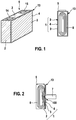
- FIG 1 is a schematic view of an electrochemical energy storage device 5 according to an embodiment of the invention.
- Said electrochemical energy storage device 5 comprises a damage identification system 1 according to a first embodiment of the present invention.
- the electrochemical energy storage device 5 is shown from two different views.
- the electrochemical energy storage device 5 comprises a housing 13.
- the housing 13 is provided with a first term in 14 and a second terminal 15, wherein electrical power can be taken from the first terminal at 14 and a second terminal 15. At least parts of the housing 13 are made of electroconductive material.
- the damage identification system 1 comprises a first contact element 2 and a second contact element 4.
- the second contact element 4 corresponds to a said outer surface of the housing 13.
- the first contact element 2 is provided inside the housing 13 and is separated from the outer surface for fire an isolating member 3.
- the isolating member 3 might be a plastic film or a separate a jelly roll. Due to the isolating member 3, the first contact element is electrically isolated from the second contact element 3.
- Both, the first contact element 2 and a second contact element 4 are made of electroconductive material.
- the second contact element 4 corresponds to the outer surface of the housing 13, which preferably is made of electroconductive material.
- the first contact element 2 preferably is made from a metal film.
- a jelly roll 6 is provided inside the housing 13.
- the jelly roll 6 is made from adding a first electrode, a second electrode, and a separator and rolling those components to a flat shape.
- the electrodes are then connected to the first term in 14 and the second terminal 15.
- the second contact element 4, i.e. the outer surface of the housing 13 is electrically connected to one of the electrodes of the jelly roll 6.
- the first contact element 2 is electrically connected to a different electrical potential, particularly to a floating potential or a predefined potential, which is determined via a electrical resistance between a electric connection of the first contact element 2 and one of the electrodes of the jelly roll 6.
- the damage identification system 1 extends nearly over the whole housing 13 such that nearly the whole electrochemical energy storage device 5 can be monitored regarding damages.
- a damage is shown in figure 2 .
- a nail 7 penetrates the electrochemical energy storage device 5.
- the nail 7 pierces through the housing 13 and through isolating member 3. Therefore, the nail east partly electrically connects the housing 13, i.e. the second contact element 4, and the first contact element 2. Due to the connection of the first contact element 2 and the second contact element 4, and damage of the electrochemical energy storage device 5 is identified. This will be explained afterwards.
- FIGs 3 and 5 are schematic views of an isolating member 3.
- the isolating member 3 comprises several openings 8 which are shaped as through holes ( figure 3 ) or as slots ( figure 4 ).
- the openings 8 define predetermined breaking points such that the isolating member collapses as soon as an external force 200 (cf. figure 5 ) exceeds a predetermined value.
- this predetermined value defines a boundary of a maximum external force 200 which is allowed to act on the electrochemical energy storage device 5. As soon this boundary is exceeded, there is a risk of damage of the jellyroll 6 which is provided inside the electrochemical energy storage device 5.
- FIG. 5 shows the damage identification system 1 according to the second embodiment of the invention. On the left side, the damage identification system 1 is shown without external force, on the right side, an external force 200 acts on the damage identification system 1.
- the damage identification system 1 according to the second embodiment comprises a first connection element 2 and the second connection element 9, which both are made from metal foils. Between those metal foils, and isolating member 3 is shown in figure 3 or figure 4 is provided. Such a damage identification system 1 can then be provided on a housing 13 of any electrochemical energy storage device 5.
- the main difference between the first embodiment and the second embodiment is the second connection element 9.
- the second connection element 9 of the damage identification system 1 according to the second embodiment is a separate member and is not provided by the outer surface of the housing 13 itself. Therefore, the housing 13 might be fabricated from a material which is nonconductive.
- Another difference between the first embodiment and the second embodiment is the isolating member is 3, which finds predetermined breaking points such that no additional element is to appease the isolating member 3.
- the isolating member 3 collapses and allows connection between the first contact element 2 and the second contact element 9. Again, due to such a connection, damage of the electrochemical energy storage device 5 is identified.
- Figure 6 is a diagram of the voltage of the first connection element 2 and the output voltage of the electrochemical energy storage device 5, which can be measured between the first terminal 14 and the second terminal 15.
- the second contact element 4, 9 is electrically connected to one of the electrodes of the jelly roll 6, i.e. to one of the terminals 14, 15.
- the first contact element 2 is connected to a floating potential.
- state voltage is an indication of damages within the damage identification system 1.
- the voltage is plotted on the axis of ordinates and the time is plotted on the axis of abscissae in figure 6 .
- the output voltage 300 of the electrochemical energy storage device 5 is constant until time 500 when penetration by nail 7 starts.
- the time 500 might also illustrate the external force 200 exceeding the predetermined value. Since the damage identification system 1 will be damaged first and electrochemical energy storage device 5 will be damaged afterwards, the voltage of the first contact element 2 which is denoted this reference numeral 400 will increase before the output voltage 300 drops due to short circuits caused by the damage.
- said increase 700 of the voltage 400 of the first contact element 2 indicates damage of the electrochemical energy storage device 5. This means, as soon as voltage 400 shows such an increase 700, countermeasures have to be started in order to avoid critical behavior of electrochemical energy storage device 5.
- the voltage 400 might also be employed to power a logical unit 10, which is shown in figure 7.
- Figure 7 shows a damage identification system 1 according to a third embodiment.
- the logical unit 10 the electrochemical energy storage device 5, the first contact element 2, and the second contact element 9 set up a circuit for supplying power to the logical unit 10.
- logical unit 10 will only be supplied with electric power in case a contact between the first contact element 2 and the second contact element 9 is established. Such a contact would only be present in case of damage. Therefore, logical unit 10 is adapted to start measures to avoid critical cell behavior of the electrochemical energy storage device 5.
- the logical unit 10 actuates a switch 12 for bridging the damaged electrochemical energy storage device 5.
- the electrochemical energy storage device 5 is isolated such that a damage of the electrochemical energy storage device 5 will not have any influence to other energy sources like other electrochemical energy storage device.
- the unit 10 might activate a fast discharge device for discharging electrochemical energy storage device 5.
- the logical unit 10 also might be a fast discharge device without further logical elements.
- the fast discharge device is adapted to shortcut the electrochemical storage device 5.
- the discharge device has to be activated by an electrical voltage. Since the first contact element 2 is electrically connected to one terminal of the electrochemical energy storage device 5 and the discharge device is electrically connected to another terminal of the electrochemical energy storage device 5 as well as to the second contact element 9, the discharge device is only prevented from being activated due to the isolating member 3. In case of damage, the first contact element 2 and the second contact element 9 come into contact such that the discharge device is activated and discharges the electrochemical storage device 5. Hence, the discharge device, which helps to prevent catastrophic behavior of he electrochemical energy storage device 5 due to damage, is activated by the damage itself. No further logical elements are required.
- FIG 8 is a view of an alternative solution of logical unit 10. Again, figure 8 is a schematic view of damage identification system 1 according to the third embodiment.
- the difference to the first alternative shown in figure 7 is the logical unit 11.
- the logical unit 11 is adapted to actuate a switch 12 which again bridges the damaged electrochemical energy storage device 5.
- the logical unit 11 will not be operated with only energy from electrochemical energy storage device 5 but rather comprises an additional power source. Therefore, the logical unit 11 is independent from electrochemical energy storage device 5. This also allows actuating switches 12 which require higher energy than that of the electrochemical energy storage device 5 is able to provide.
- Such a design is preferable in case a fast discharge device is provided as a semiconductor device.
Landscapes
- Chemical & Material Sciences (AREA)
- Chemical Kinetics & Catalysis (AREA)
- Electrochemistry (AREA)
- General Chemical & Material Sciences (AREA)
- Engineering & Computer Science (AREA)
- Manufacturing & Machinery (AREA)
- Battery Mounting, Suspending (AREA)
- Secondary Cells (AREA)
- Connection Of Batteries Or Terminals (AREA)
Priority Applications (1)
| Application Number | Priority Date | Filing Date | Title |
|---|---|---|---|
| EP16205506.5A EP3340331B1 (de) | 2016-12-20 | 2016-12-20 | Beschädigungserkennungssystem für einen elektrochemischen speicher |
Applications Claiming Priority (1)
| Application Number | Priority Date | Filing Date | Title |
|---|---|---|---|
| EP16205506.5A EP3340331B1 (de) | 2016-12-20 | 2016-12-20 | Beschädigungserkennungssystem für einen elektrochemischen speicher |
Publications (2)
| Publication Number | Publication Date |
|---|---|
| EP3340331A1 true EP3340331A1 (de) | 2018-06-27 |
| EP3340331B1 EP3340331B1 (de) | 2021-04-14 |
Family
ID=57570858
Family Applications (1)
| Application Number | Title | Priority Date | Filing Date |
|---|---|---|---|
| EP16205506.5A Active EP3340331B1 (de) | 2016-12-20 | 2016-12-20 | Beschädigungserkennungssystem für einen elektrochemischen speicher |
Country Status (1)
| Country | Link |
|---|---|
| EP (1) | EP3340331B1 (de) |
Citations (3)
| Publication number | Priority date | Publication date | Assignee | Title |
|---|---|---|---|---|
| DE102011120505A1 (de) * | 2011-12-07 | 2013-06-13 | Daimler Ag | Batterie mit einer Anzahl von elektrisch miteinander verschalteten Einzelzellen |
| DE102012005979A1 (de) | 2012-03-23 | 2013-09-26 | Fraunhofer-Gesellschaft zur Förderung der angewandten Forschung e.V. | Elektrisches Überbrückungselement und Energiespeicher mit dem Überbrückungselement |
| US20140065453A1 (en) * | 2012-08-30 | 2014-03-06 | Daimler Ag | Electrochemical energy storage cell and electrochemical energy storage device comprising at least one such electrochemical energy storage cell |
-
2016
- 2016-12-20 EP EP16205506.5A patent/EP3340331B1/de active Active
Patent Citations (3)
| Publication number | Priority date | Publication date | Assignee | Title |
|---|---|---|---|---|
| DE102011120505A1 (de) * | 2011-12-07 | 2013-06-13 | Daimler Ag | Batterie mit einer Anzahl von elektrisch miteinander verschalteten Einzelzellen |
| DE102012005979A1 (de) | 2012-03-23 | 2013-09-26 | Fraunhofer-Gesellschaft zur Förderung der angewandten Forschung e.V. | Elektrisches Überbrückungselement und Energiespeicher mit dem Überbrückungselement |
| US20140065453A1 (en) * | 2012-08-30 | 2014-03-06 | Daimler Ag | Electrochemical energy storage cell and electrochemical energy storage device comprising at least one such electrochemical energy storage cell |
Also Published As
| Publication number | Publication date |
|---|---|
| EP3340331B1 (de) | 2021-04-14 |
Similar Documents
| Publication | Publication Date | Title |
|---|---|---|
| EP3843195B1 (de) | Vorrichtung zur detektion von thermischem durchgehen, batteriesystem und verfahren zur detektion von thermischem durchgehen für batteriesystem | |
| KR100764618B1 (ko) | 안전장치를 구비하고 있는 이차전지 | |
| US11024893B2 (en) | Battery of modular construction having improved safety properties | |
| US20150162593A1 (en) | Apparatus for preventing over-charge for battery of vehicle | |
| US20150207133A1 (en) | Battery having a thermal switch | |
| US20160111757A1 (en) | Battery module with fusible conductors | |
| US20160329550A1 (en) | Battery cell with surge protector | |
| JP2007265658A (ja) | 蓄電素子モジュール | |
| EP4576376A1 (de) | Batterieabdeckplatte, batterie, batteriepack und energiespeichersystem | |
| CN113270655B (zh) | 电池系统以及电池的异常判定方法 | |
| KR20160113888A (ko) | 배터리 팩 | |
| JP6285540B2 (ja) | 再設定されることができる安全装置を有する電池及び前記電池のための好適な極スタッド | |
| EP3680955B1 (de) | Batteriesystem | |
| KR20110129870A (ko) | 갈바닉 셀용 보호 유닛 | |
| JP5002958B2 (ja) | 電池 | |
| CN109155388A (zh) | 电池保护装置 | |
| DE102014208627A1 (de) | Batteriezelle | |
| KR102425827B1 (ko) | 배터리 모듈 | |
| EP3340331B1 (de) | Beschädigungserkennungssystem für einen elektrochemischen speicher | |
| US10903476B2 (en) | Battery module and battery pack including same | |
| CN104093883A (zh) | 蓄电池、机动车以及用于运行蓄电池的方法 | |
| EP3336956B1 (de) | Verfahren zur überwachung einer entladungsvorrichtung einer batterie | |
| US20240072399A1 (en) | Disconnection device and short-circuiting device comprising a heat-activatable element | |
| EP3435445A1 (de) | Auslöservorrichtung, sicherheitsvorrichtung, stromspeichervorrichtung und verfahren zur auslösung einer sicherheitsvorrichtung für eine stromspeichereinheit | |
| CN110650860B (zh) | 储存装置、机动车辆以及用于运行储存装置的方法 |
Legal Events
| Date | Code | Title | Description |
|---|---|---|---|
| PUAI | Public reference made under article 153(3) epc to a published international application that has entered the european phase |
Free format text: ORIGINAL CODE: 0009012 |
|
| STAA | Information on the status of an ep patent application or granted ep patent |
Free format text: STATUS: THE APPLICATION HAS BEEN PUBLISHED |
|
| AK | Designated contracting states |
Kind code of ref document: A1 Designated state(s): AL AT BE BG CH CY CZ DE DK EE ES FI FR GB GR HR HU IE IS IT LI LT LU LV MC MK MT NL NO PL PT RO RS SE SI SK SM TR |
|
| AX | Request for extension of the european patent |
Extension state: BA ME |
|
| STAA | Information on the status of an ep patent application or granted ep patent |
Free format text: STATUS: REQUEST FOR EXAMINATION WAS MADE |
|
| 17P | Request for examination filed |
Effective date: 20181219 |
|
| RBV | Designated contracting states (corrected) |
Designated state(s): AL AT BE BG CH CY CZ DE DK EE ES FI FR GB GR HR HU IE IS IT LI LT LU LV MC MK MT NL NO PL PT RO RS SE SI SK SM TR |
|
| RAP1 | Party data changed (applicant data changed or rights of an application transferred) |
Owner name: GS YUASA INTERNATIONAL LTD. Owner name: ROBERT BOSCH GMBH |
|
| STAA | Information on the status of an ep patent application or granted ep patent |
Free format text: STATUS: EXAMINATION IS IN PROGRESS |
|
| 17Q | First examination report despatched |
Effective date: 20191002 |
|
| RAP1 | Party data changed (applicant data changed or rights of an application transferred) |
Owner name: GS YUASA INTERNATIONAL LTD. Owner name: ROBERT BOSCH GMBH |
|
| GRAP | Despatch of communication of intention to grant a patent |
Free format text: ORIGINAL CODE: EPIDOSNIGR1 |
|
| STAA | Information on the status of an ep patent application or granted ep patent |
Free format text: STATUS: GRANT OF PATENT IS INTENDED |
|
| INTG | Intention to grant announced |
Effective date: 20201113 |
|
| RIN1 | Information on inventor provided before grant (corrected) |
Inventor name: BUTZMANN, STEFAN Inventor name: FRIEDRICH, MARCO |
|
| GRAS | Grant fee paid |
Free format text: ORIGINAL CODE: EPIDOSNIGR3 |
|
| GRAA | (expected) grant |
Free format text: ORIGINAL CODE: 0009210 |
|
| STAA | Information on the status of an ep patent application or granted ep patent |
Free format text: STATUS: THE PATENT HAS BEEN GRANTED |
|
| AK | Designated contracting states |
Kind code of ref document: B1 Designated state(s): AL AT BE BG CH CY CZ DE DK EE ES FI FR GB GR HR HU IE IS IT LI LT LU LV MC MK MT NL NO PL PT RO RS SE SI SK SM TR |
|
| REG | Reference to a national code |
Ref country code: GB Ref legal event code: FG4D |
|
| REG | Reference to a national code |
Ref country code: CH Ref legal event code: EP |
|
| REG | Reference to a national code |
Ref country code: DE Ref legal event code: R096 Ref document number: 602016056011 Country of ref document: DE |
|
| REG | Reference to a national code |
Ref country code: IE Ref legal event code: FG4D |
|
| REG | Reference to a national code |
Ref country code: AT Ref legal event code: REF Ref document number: 1383250 Country of ref document: AT Kind code of ref document: T Effective date: 20210515 |
|
| REG | Reference to a national code |
Ref country code: LT Ref legal event code: MG9D |
|
| REG | Reference to a national code |
Ref country code: AT Ref legal event code: MK05 Ref document number: 1383250 Country of ref document: AT Kind code of ref document: T Effective date: 20210414 |
|
| REG | Reference to a national code |
Ref country code: NL Ref legal event code: MP Effective date: 20210414 |
|
| PG25 | Lapsed in a contracting state [announced via postgrant information from national office to epo] |
Ref country code: HR Free format text: LAPSE BECAUSE OF FAILURE TO SUBMIT A TRANSLATION OF THE DESCRIPTION OR TO PAY THE FEE WITHIN THE PRESCRIBED TIME-LIMIT Effective date: 20210414 Ref country code: BG Free format text: LAPSE BECAUSE OF FAILURE TO SUBMIT A TRANSLATION OF THE DESCRIPTION OR TO PAY THE FEE WITHIN THE PRESCRIBED TIME-LIMIT Effective date: 20210714 Ref country code: AT Free format text: LAPSE BECAUSE OF FAILURE TO SUBMIT A TRANSLATION OF THE DESCRIPTION OR TO PAY THE FEE WITHIN THE PRESCRIBED TIME-LIMIT Effective date: 20210414 Ref country code: FI Free format text: LAPSE BECAUSE OF FAILURE TO SUBMIT A TRANSLATION OF THE DESCRIPTION OR TO PAY THE FEE WITHIN THE PRESCRIBED TIME-LIMIT Effective date: 20210414 Ref country code: LT Free format text: LAPSE BECAUSE OF FAILURE TO SUBMIT A TRANSLATION OF THE DESCRIPTION OR TO PAY THE FEE WITHIN THE PRESCRIBED TIME-LIMIT Effective date: 20210414 Ref country code: NL Free format text: LAPSE BECAUSE OF FAILURE TO SUBMIT A TRANSLATION OF THE DESCRIPTION OR TO PAY THE FEE WITHIN THE PRESCRIBED TIME-LIMIT Effective date: 20210414 |
|
| PG25 | Lapsed in a contracting state [announced via postgrant information from national office to epo] |
Ref country code: PT Free format text: LAPSE BECAUSE OF FAILURE TO SUBMIT A TRANSLATION OF THE DESCRIPTION OR TO PAY THE FEE WITHIN THE PRESCRIBED TIME-LIMIT Effective date: 20210816 Ref country code: PL Free format text: LAPSE BECAUSE OF FAILURE TO SUBMIT A TRANSLATION OF THE DESCRIPTION OR TO PAY THE FEE WITHIN THE PRESCRIBED TIME-LIMIT Effective date: 20210414 Ref country code: NO Free format text: LAPSE BECAUSE OF FAILURE TO SUBMIT A TRANSLATION OF THE DESCRIPTION OR TO PAY THE FEE WITHIN THE PRESCRIBED TIME-LIMIT Effective date: 20210714 Ref country code: RS Free format text: LAPSE BECAUSE OF FAILURE TO SUBMIT A TRANSLATION OF THE DESCRIPTION OR TO PAY THE FEE WITHIN THE PRESCRIBED TIME-LIMIT Effective date: 20210414 Ref country code: SE Free format text: LAPSE BECAUSE OF FAILURE TO SUBMIT A TRANSLATION OF THE DESCRIPTION OR TO PAY THE FEE WITHIN THE PRESCRIBED TIME-LIMIT Effective date: 20210414 Ref country code: IS Free format text: LAPSE BECAUSE OF FAILURE TO SUBMIT A TRANSLATION OF THE DESCRIPTION OR TO PAY THE FEE WITHIN THE PRESCRIBED TIME-LIMIT Effective date: 20210814 Ref country code: GR Free format text: LAPSE BECAUSE OF FAILURE TO SUBMIT A TRANSLATION OF THE DESCRIPTION OR TO PAY THE FEE WITHIN THE PRESCRIBED TIME-LIMIT Effective date: 20210715 Ref country code: LV Free format text: LAPSE BECAUSE OF FAILURE TO SUBMIT A TRANSLATION OF THE DESCRIPTION OR TO PAY THE FEE WITHIN THE PRESCRIBED TIME-LIMIT Effective date: 20210414 |
|
| REG | Reference to a national code |
Ref country code: DE Ref legal event code: R097 Ref document number: 602016056011 Country of ref document: DE |
|
| PG25 | Lapsed in a contracting state [announced via postgrant information from national office to epo] |
Ref country code: RO Free format text: LAPSE BECAUSE OF FAILURE TO SUBMIT A TRANSLATION OF THE DESCRIPTION OR TO PAY THE FEE WITHIN THE PRESCRIBED TIME-LIMIT Effective date: 20210414 Ref country code: ES Free format text: LAPSE BECAUSE OF FAILURE TO SUBMIT A TRANSLATION OF THE DESCRIPTION OR TO PAY THE FEE WITHIN THE PRESCRIBED TIME-LIMIT Effective date: 20210414 Ref country code: DK Free format text: LAPSE BECAUSE OF FAILURE TO SUBMIT A TRANSLATION OF THE DESCRIPTION OR TO PAY THE FEE WITHIN THE PRESCRIBED TIME-LIMIT Effective date: 20210414 Ref country code: EE Free format text: LAPSE BECAUSE OF FAILURE TO SUBMIT A TRANSLATION OF THE DESCRIPTION OR TO PAY THE FEE WITHIN THE PRESCRIBED TIME-LIMIT Effective date: 20210414 Ref country code: CZ Free format text: LAPSE BECAUSE OF FAILURE TO SUBMIT A TRANSLATION OF THE DESCRIPTION OR TO PAY THE FEE WITHIN THE PRESCRIBED TIME-LIMIT Effective date: 20210414 Ref country code: SM Free format text: LAPSE BECAUSE OF FAILURE TO SUBMIT A TRANSLATION OF THE DESCRIPTION OR TO PAY THE FEE WITHIN THE PRESCRIBED TIME-LIMIT Effective date: 20210414 Ref country code: SK Free format text: LAPSE BECAUSE OF FAILURE TO SUBMIT A TRANSLATION OF THE DESCRIPTION OR TO PAY THE FEE WITHIN THE PRESCRIBED TIME-LIMIT Effective date: 20210414 |
|
| PLBE | No opposition filed within time limit |
Free format text: ORIGINAL CODE: 0009261 |
|
| STAA | Information on the status of an ep patent application or granted ep patent |
Free format text: STATUS: NO OPPOSITION FILED WITHIN TIME LIMIT |
|
| 26N | No opposition filed |
Effective date: 20220117 |
|
| PG25 | Lapsed in a contracting state [announced via postgrant information from national office to epo] |
Ref country code: IS Free format text: LAPSE BECAUSE OF FAILURE TO SUBMIT A TRANSLATION OF THE DESCRIPTION OR TO PAY THE FEE WITHIN THE PRESCRIBED TIME-LIMIT Effective date: 20210814 Ref country code: AL Free format text: LAPSE BECAUSE OF FAILURE TO SUBMIT A TRANSLATION OF THE DESCRIPTION OR TO PAY THE FEE WITHIN THE PRESCRIBED TIME-LIMIT Effective date: 20210414 |
|
| PG25 | Lapsed in a contracting state [announced via postgrant information from national office to epo] |
Ref country code: MC Free format text: LAPSE BECAUSE OF FAILURE TO SUBMIT A TRANSLATION OF THE DESCRIPTION OR TO PAY THE FEE WITHIN THE PRESCRIBED TIME-LIMIT Effective date: 20210414 Ref country code: IT Free format text: LAPSE BECAUSE OF FAILURE TO SUBMIT A TRANSLATION OF THE DESCRIPTION OR TO PAY THE FEE WITHIN THE PRESCRIBED TIME-LIMIT Effective date: 20210414 |
|
| REG | Reference to a national code |
Ref country code: CH Ref legal event code: PL |
|
| GBPC | Gb: european patent ceased through non-payment of renewal fee |
Effective date: 20211220 |
|
| REG | Reference to a national code |
Ref country code: BE Ref legal event code: MM Effective date: 20211231 |
|
| PG25 | Lapsed in a contracting state [announced via postgrant information from national office to epo] |
Ref country code: LU Free format text: LAPSE BECAUSE OF NON-PAYMENT OF DUE FEES Effective date: 20211220 Ref country code: IE Free format text: LAPSE BECAUSE OF NON-PAYMENT OF DUE FEES Effective date: 20211220 Ref country code: GB Free format text: LAPSE BECAUSE OF NON-PAYMENT OF DUE FEES Effective date: 20211220 |
|
| PG25 | Lapsed in a contracting state [announced via postgrant information from national office to epo] |
Ref country code: FR Free format text: LAPSE BECAUSE OF NON-PAYMENT OF DUE FEES Effective date: 20211231 Ref country code: BE Free format text: LAPSE BECAUSE OF NON-PAYMENT OF DUE FEES Effective date: 20211231 |
|
| PG25 | Lapsed in a contracting state [announced via postgrant information from national office to epo] |
Ref country code: LI Free format text: LAPSE BECAUSE OF NON-PAYMENT OF DUE FEES Effective date: 20211231 Ref country code: CH Free format text: LAPSE BECAUSE OF NON-PAYMENT OF DUE FEES Effective date: 20211231 |
|
| PG25 | Lapsed in a contracting state [announced via postgrant information from national office to epo] |
Ref country code: HU Free format text: LAPSE BECAUSE OF FAILURE TO SUBMIT A TRANSLATION OF THE DESCRIPTION OR TO PAY THE FEE WITHIN THE PRESCRIBED TIME-LIMIT; INVALID AB INITIO Effective date: 20161220 |
|
| PGFP | Annual fee paid to national office [announced via postgrant information from national office to epo] |
Ref country code: DE Payment date: 20221230 Year of fee payment: 7 |
|
| PG25 | Lapsed in a contracting state [announced via postgrant information from national office to epo] |
Ref country code: CY Free format text: LAPSE BECAUSE OF FAILURE TO SUBMIT A TRANSLATION OF THE DESCRIPTION OR TO PAY THE FEE WITHIN THE PRESCRIBED TIME-LIMIT Effective date: 20210414 |
|
| PG25 | Lapsed in a contracting state [announced via postgrant information from national office to epo] |
Ref country code: MK Free format text: LAPSE BECAUSE OF FAILURE TO SUBMIT A TRANSLATION OF THE DESCRIPTION OR TO PAY THE FEE WITHIN THE PRESCRIBED TIME-LIMIT Effective date: 20210414 |
|
| PG25 | Lapsed in a contracting state [announced via postgrant information from national office to epo] |
Ref country code: TR Free format text: LAPSE BECAUSE OF FAILURE TO SUBMIT A TRANSLATION OF THE DESCRIPTION OR TO PAY THE FEE WITHIN THE PRESCRIBED TIME-LIMIT Effective date: 20210414 |
|
| REG | Reference to a national code |
Ref country code: DE Ref legal event code: R119 Ref document number: 602016056011 Country of ref document: DE |
|
| PG25 | Lapsed in a contracting state [announced via postgrant information from national office to epo] |
Ref country code: MT Free format text: LAPSE BECAUSE OF FAILURE TO SUBMIT A TRANSLATION OF THE DESCRIPTION OR TO PAY THE FEE WITHIN THE PRESCRIBED TIME-LIMIT Effective date: 20210414 |
|
| PG25 | Lapsed in a contracting state [announced via postgrant information from national office to epo] |
Ref country code: DE Free format text: LAPSE BECAUSE OF NON-PAYMENT OF DUE FEES Effective date: 20240702 |
|
| PG25 | Lapsed in a contracting state [announced via postgrant information from national office to epo] |
Ref country code: DE Free format text: LAPSE BECAUSE OF NON-PAYMENT OF DUE FEES Effective date: 20240702 |