EP3340271A1 - Umschaltungskontaktstückanordnung und hilfsschalter damit - Google Patents
Umschaltungskontaktstückanordnung und hilfsschalter damit Download PDFInfo
- Publication number
- EP3340271A1 EP3340271A1 EP17208586.2A EP17208586A EP3340271A1 EP 3340271 A1 EP3340271 A1 EP 3340271A1 EP 17208586 A EP17208586 A EP 17208586A EP 3340271 A1 EP3340271 A1 EP 3340271A1
- Authority
- EP
- European Patent Office
- Prior art keywords
- contact
- movable contact
- change
- contact piece
- piece assembly
- Prior art date
- Legal status (The legal status is an assumption and is not a legal conclusion. Google has not performed a legal analysis and makes no representation as to the accuracy of the status listed.)
- Granted
Links
Images



Classifications
-
- H—ELECTRICITY
- H01—ELECTRIC ELEMENTS
- H01H—ELECTRIC SWITCHES; RELAYS; SELECTORS; EMERGENCY PROTECTIVE DEVICES
- H01H1/00—Contacts
- H01H1/50—Means for increasing contact pressure, preventing vibration of contacts, holding contacts together after engagement, or biasing contacts to the open position
-
- H—ELECTRICITY
- H01—ELECTRIC ELEMENTS
- H01H—ELECTRIC SWITCHES; RELAYS; SELECTORS; EMERGENCY PROTECTIVE DEVICES
- H01H71/00—Details of the protective switches or relays covered by groups H01H73/00 - H01H83/00
- H01H71/10—Operating or release mechanisms
- H01H71/12—Automatic release mechanisms with or without manual release
- H01H71/46—Automatic release mechanisms with or without manual release having means for operating auxiliary contacts additional to the main contacts
- H01H71/462—Automatic release mechanisms with or without manual release having means for operating auxiliary contacts additional to the main contacts housed in a separate casing, juxtaposed to and having the same general contour as the main casing
-
- H—ELECTRICITY
- H01—ELECTRIC ELEMENTS
- H01H—ELECTRIC SWITCHES; RELAYS; SELECTORS; EMERGENCY PROTECTIVE DEVICES
- H01H1/00—Contacts
- H01H1/12—Contacts characterised by the manner in which co-operating contacts engage
- H01H1/14—Contacts characterised by the manner in which co-operating contacts engage by abutting
- H01H1/22—Contacts characterised by the manner in which co-operating contacts engage by abutting with rigid pivoted member carrying the moving contact
- H01H1/221—Contacts characterised by the manner in which co-operating contacts engage by abutting with rigid pivoted member carrying the moving contact and a contact pressure spring acting between the pivoted member and a supporting member
- H01H1/225—Contacts characterised by the manner in which co-operating contacts engage by abutting with rigid pivoted member carrying the moving contact and a contact pressure spring acting between the pivoted member and a supporting member the supporting member being pivotable
-
- H—ELECTRICITY
- H01—ELECTRIC ELEMENTS
- H01H—ELECTRIC SWITCHES; RELAYS; SELECTORS; EMERGENCY PROTECTIVE DEVICES
- H01H3/00—Mechanisms for operating contacts
- H01H3/32—Driving mechanisms, i.e. for transmitting driving force to the contacts
-
- H—ELECTRICITY
- H01—ELECTRIC ELEMENTS
- H01H—ELECTRIC SWITCHES; RELAYS; SELECTORS; EMERGENCY PROTECTIVE DEVICES
- H01H71/00—Details of the protective switches or relays covered by groups H01H73/00 - H01H83/00
- H01H71/10—Operating or release mechanisms
- H01H71/12—Automatic release mechanisms with or without manual release
- H01H71/46—Automatic release mechanisms with or without manual release having means for operating auxiliary contacts additional to the main contacts
- H01H2071/467—Automatic release mechanisms with or without manual release having means for operating auxiliary contacts additional to the main contacts with history indication, e.g. of trip and/or kind of trip, number of short circuits etc.
Definitions
- the present invention relates to the field of low-voltage electrics, and in particular to a change-over contact piece assembly and an auxiliary switch having the change-over contact piece assembly.
- An object of the present invention is to provide a change-over contact piece assembly which can ensure that a movable contact carrier applies the same contact piece pressure to stationary contact pieces on upper and lower sides to thereby ensure the stability of electrical contact between a movable contact and a stationary contact.
- the present invention provides a change-over contact piece assembly for achieving switching between different electrical circuits, the change-over contact piece assembly comprising: a first stationary contact piece with a first stationary contact provided thereon; a second stationary contact piece with a second stationary contact provided thereon; and a movable contact piece assembly comprising: a movable contact carrier connectable to a rotary member; a movable contact fixed on the movable contact carrier; and a reset member, with one end thereof being connected to the movable contact carrier, and the other end thereof being connected to the rotary member, wherein as the rotary member rotates, the movable contact can be driven into contact with the first stationary contact or the second stationary contact.
- the movable contact carrier has a plate-like structure and has a thickness, and the movable contact carrier is provided with at least two clamping portions so as to be separately fitted with and clamped onto the rotary member.
- the movable contact carrier has a large current-carrying section, which can not only improve a current-carrying capacity, but also effectively reduce an increase in temperature and power consumption.
- the movable contact carrier comprises a first extension and a second extension, and the first extension and the second extension form an L-shaped structure, the movable contact being located at an end of the first extension.
- a bent portion bent toward the first extension is further provided at an end of the second extension, and the rotary member is provided with an accommodation groove for accommodating the bent portion, such that the bent portion can be clamped in the accommodation groove.
- the first extension is also provided with a first mounting groove
- the rotary member is also provided with a clamping hook
- the first mounting groove and the clamping hook can be fitted and clamped together.
- the first extension is also provided with a second mounting groove
- the rotary member is also provided with a mounting post, one end of the reset member being hooked in the second mounting groove, and the other end of the reset member being sleeved over the mounting post.
- the rotary member is also provided with two locating protrusions for bearing the movable contact carrier, when the rotary member drives the movable contact carrier to rotate in a first direction and into place, the movable contact carrier takes a first locating protrusion as a rotation fulcrum, and when the rotary member drives the movable contact carrier to rotate in a second direction and into place, the movable contact carrier takes a second locating protrusion as the rotation fulcrum.
- contact pressure reverses, so that when the movable contact is brought into contact with different stationary contacts, contact pressure is provided by the reset member, and the stability of the contact pressure is ensured.
- the present invention also provides an auxiliary switch, a housing of the auxiliary switch being internally provided with at least one change-over contact piece assembly which has the above-mentioned structure and features or a combination thereof and which is located on at least one side of the housing.
- the movable contact carrier of the change-over contact piece assembly is selectively connected to a rotating plate of the auxiliary switch.
- the first stationary contact piece and the second stationary contact piece are each connected to two wiring terminals located on one side of the housing, and as the rotating plate rotates, the movable contact can be driven into contact with the first stationary contact or the second stationary contact so as to achieve switching between at least two electrical circuits.
- the product structure is more compact, the movable contact carrier does not easily experience plastic deformation, and moreover, the stability of the electrical contact of the movable contact is better, the current-carrying capability is stronger, and at the same time, the increase in temperature and the power consumption are reduced.
- the present invention also provides an auxiliary switch, a housing of which being internally provided with two change-over contact piece assemblies which have the above-mentioned structure and features or a combination thereof, and a first rotating plate and a second rotating plate which are arranged concentrically, wherein a first change-over contact piece assembly and a second change-over contact piece assembly are respectively located on two sides of the housing, the movable contact carrier of the first change-over contact piece assembly is connected to the first rotating plate of the auxiliary switch, and the movable contact carrier of the second change-over contact piece assembly is connected to the second rotating plate of the auxiliary switch, as the first rotating plate rotates, the movable contact can be driven into contact with the first stationary contact or the second stationary contact, and as the second rotating plate rotates, the movable contact can be driven into contact with the first stationary contact or the second stationary contact so as to achieve switching between four electrical circuits.
- the product structure is more compact, the movable contact carrier does not easily experience plastic deformation, and moreover, the stability of the electrical contact of the movable contact is better, the current-carrying capability is stronger, and at the same time, the increase in temperature and the power consumption are reduced.
- exemplary means “serving as an example, instance, or description,” and any illustration and embodiment described as “exemplary” herein should not be interpreted as a more preferred or a more advantageous technical solution.
- the present invention relates to a change-over contact piece assembly which can be used for achieving switching between different electrical circuits.
- the change-over contact piece assembly comprises a first stationary contact piece 81a; 81b, a second stationary contact piece 82a; 82b and a movable contact piece assembly 83a; 83b.
- the first stationary contact piece is provided with a first stationary contact S2; S5.
- the second stationary contact piece is provided with a second stationary contact S3; S6.
- the movable contact piece assembly 83a; 83b comprises a movable contact 85a; 85b, a movable contact carrier 84a; 84b, and a reset member 86a; 86b, wherein the movable contact carrier 84a; 84b is connectable to a rotary member 60; 50 (equivalent to a second rotating plate 60 and a first rotating plate 50 described below).
- the movable contact 85a; 85b is fixed on the movable contact carrier 84a; 84b.
- One end of the reset member 86a; 86b is connected to the movable contact carrier 84a; 84b, and the other end of the reset member 86a; 86b is connected to the rotary member 60; 50.
- the movable contact 85a; 85b can be driven into contact with the first stationary contact S2; S5 or the second stationary contact S3; S6 so as to achieve switching between different circuits.
- the present invention further relates to an auxiliary switch 100, a housing 10 of which is internally provided with a change-over contact piece assembly having the above-mentioned structure and features or a combination thereof.
- a structural schematic diagram of the interior of the auxiliary switch 100 of the present invention is shown.
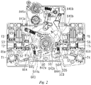
- Figs. 2 and 3 are respectively structural schematic diagrams of the interior of the auxiliary switch when an operating handle 101 is in an OFF position and in an ON position.
- two mechanisms namely, an AS mechanism and an FC mechanism
- the AS mechanism comprises an operating handle 101, a release assembly 20, a connection rod assembly 30, a first lock rod 40, and a first rotating plate 50.
- the FC mechanism comprises an operating handle 101, a release assembly 20, a connection rod assembly 30, a first lock rod 40, a second lock rod 70, and a second rotating plate 60.
- first rotating plate 50 and the second rotating plate 60 are arranged concentrically, the first rotating plate 50 can drive the second rotating plate 60 to rotate, and the AS mechanism and the FC mechanism share the operating handle 101, the release assembly 20, the first lock rod 40 and the connection rod assembly 30 therebetween.
- Six wiring terminals T1, T2, T3, T4, T5 and T6 are arranged on two sides of the housing 10, three wiring terminals T1, T2, T3 and T4, T5, T6 being arranged on each side of the housing 10 so that four different electrical circuits can be formed inside the housing 10.
- two change-over contact piece assemblies are arranged inside the housing 10. As shown in Figs. 1 to 3 , a first change-over contact piece assembly and a second change-over contact piece assembly are respectively located on the two sides of the housing 10, the movable contact carrier 84a of the first change-over contact piece assembly is connected to the second rotating plate 60 of the auxiliary switch 100, and the movable contact carrier 84b of the second change-over contact piece assembly is connected to the first rotating plate 50 of the auxiliary switch 100.
- a pair of wiring terminals T1 and T4 away from the operating handle 101 are respectively electrically connected to the movable contact carrier 84a on the second rotating plate 60 and the movable contact carrier 84b on the first rotating plate 50 via flexible wires S7, S8, and respectively remain in a normally closed state.
- the remaining two pairs of wiring terminals T2, T3, T5, T6 are respectively provided with two pairs of stationary contact pieces S2, S3, S5, S6.
- only one change-over contact piece assembly may be provided inside the housing 10 of the auxiliary switch 100.
- the movable contact carrier may be selectively connected to one of the rotating plates of the auxiliary switch 100, for example, same is connectable to the first rotating plate 50 or the second rotating plate 60.
- the movable contact 85b or 85a on the corresponding side thereof can be driven into contact with the first stationary contact S2; S5 or the second stationary contact S3; S6 so as to achieve switching between at least two electrical circuits.
- the movable contact carrier 84a has a plate-like structure and has a thickness
- the movable contact carrier 84a is provided with at least two clamping portions 841a, 848a so as to be separately fitted with and clamped onto the second rotating plate 60.
- the movable contact carrier 84b has a plate-like structure and has a thickness
- the movable contact carrier 84b is provided with at least two clamping portions 841b, 848b so as to be separately fitted with and clamped onto the first rotating plate 50.
- the movable contact carrier has a large current-carrying section, which can not only improve a current-carrying capacity, but also effectively reduce an increase in temperature and power consumption.
- the movable contact carrier 84a comprises a first extension 843a and a second extension 842a.
- the first extension 843a and the second extension 842a form an L-shaped structure, the movable contact 85a being located at an end of the first extension 843a.
- a bent portion 844a bent toward the first extension 843a is further provided at an end of the second extension 842a.
- the second rotating plate 60 is provided with an accommodation groove 601 for accommodating the bent portion 844a, such that the bent portion 844a can be clamped in the accommodation groove 601.
- the movable contact carrier 84b comprises a first extension 843b and a second extension 842b.
- the first extension 843b and the second extension 842b form an L-shaped structure, the movable contact 85b being located at an end of the first extension 843b.
- a bent portion 844b bent toward the first extension 843b is further provided at an end of the second extension 842b.
- the first rotating plate 50 is provided with an accommodation groove 501 for accommodating the bent portion 844b, such that the bent portion 844b can be clamped in the accommodation groove 501.
- first extension 843a is also provided with a first mounting groove 845a
- second rotating plate 60 is also provided with a clamping hook 602
- first mounting groove 845a and the clamping hook 602 can be fitted and clamped together
- first extension 843b is also provided with a first mounting groove 845b
- the first rotating plate 50 is also provided with a clamping hook 502
- the first mounting groove 845b and the clamping hook 502 can be fitted and clamped together.
- the first extension 843a is also provided with a second mounting groove 846a
- the second rotating plate 60 is also provided with a mounting post 603, one end of the reset member 86a being hooked in the second mounting groove 846a, and the other end of the reset member 86a being sleeved over the mounting post 603.
- the first extension 843b is also provided with a second mounting groove 846b
- the first rotating plate 50 is also provided with a mounting post 503, one end of the reset member 86b being hooked in the second mounting groove 846b, and the other end of the reset member 86b being sleeved over the mounting post 503.
- the second rotating plate 60 is also provided with two locating protrusions 604, 605, and the first extension 843a can selectively abut against either one of the locating protrusions so that, when the second rotating plate 60 drives the movable contact carrier 84a to rotate in a first direction, the movable contact carrier 84a takes the first locating protrusion 604 as a rotation fulcrum, and when the second rotating plate 60 drives the movable contact carrier 84a to rotate in a second direction, the movable contact carrier 84a takes the second locating protrusion 605 as the rotation fulcrum.
- the first rotating plate 50 is also provided with two locating protrusions 504, 505, and the first extension 843b can selectively abut against either one of the locating protrusions so that, when the first rotating plate 50 drives the movable contact carrier 84b to rotate in the first direction, the movable contact carrier 84b takes the first locating protrusion 504 as a rotation fulcrum, and when the rotary member 50 drives the movable contact carrier 84b to rotate in the second direction, the movable contact carrier 84b takes the second locating protrusion 505 as the rotation fulcrum.
- contact pressure reverses, so that when the movable contact is brought into contact with different stationary contacts, contact pressure is provided by the reset member, and the stability of the contact pressure is ensured.
- the contact pressure of the contact thereof is provided by the reset member, a tension action point is located on the movable contact piece close to a fulcrum, and the influence of the accumulated tolerance of parts on a reset force is reduced by a lever, therefore, the influence of the dimensional tolerance of the mechanical parts on the contact pressure of the contact can be effectively reduced. Since the reset member has a more stable pull force, the stability of the contact pressure can be ensured. With the change of the two fulcrums, the contact pressure reverses, so that when the movable contact is brought into contact with different stationary contacts, contact pressure is provided by the reset member, and a stable contact pressure is provided.
- the movable contact carrier of the present invention has a large current-carrying section, the current-carrying capacity can be increased, and an increase in temperature and power consumption can be reduced.
- the movable contact carrier has a short length, which can meet the requirements for the spatial compactness of a product. Since the movable contact carrier has a high degree of rigidity, plastic deformation cannot occur.
- each embodiment does not only comprise an independent technical solution, and this narrative manner of the description is only for clarity.
- the description shall be regarded as a whole, and the technical solution in each of the embodiments can also be suitably combined to form other implementations that can be understood by a person skilled in the art.
Landscapes
- Breakers (AREA)
- Rotary Switch, Piano Key Switch, And Lever Switch (AREA)
- Manufacture Of Switches (AREA)
Applications Claiming Priority (1)
| Application Number | Priority Date | Filing Date | Title |
|---|---|---|---|
| CN201611199511.6A CN108231440B (zh) | 2016-12-22 | 2016-12-22 | 转换触片组件及具有其的辅助开关 |
Publications (2)
| Publication Number | Publication Date |
|---|---|
| EP3340271A1 true EP3340271A1 (de) | 2018-06-27 |
| EP3340271B1 EP3340271B1 (de) | 2019-10-16 |
Family
ID=60674035
Family Applications (1)
| Application Number | Title | Priority Date | Filing Date |
|---|---|---|---|
| EP17208586.2A Active EP3340271B1 (de) | 2016-12-22 | 2017-12-19 | Umschaltungskontaktstückanordnung und hilfsschalter damit |
Country Status (2)
| Country | Link |
|---|---|
| EP (1) | EP3340271B1 (de) |
| CN (1) | CN108231440B (de) |
Citations (4)
| Publication number | Priority date | Publication date | Assignee | Title |
|---|---|---|---|---|
| EP0667630A1 (de) * | 1994-02-11 | 1995-08-16 | Siemens Aktiengesellschaft | Schalteinrichtung mit drehbarem Tragkörper für Kontaktträger |
| EP0951044A1 (de) * | 1998-04-17 | 1999-10-20 | Schneider Electric Industries SA | Hilfseinheit mit einer Anzeigevorrichtung anpassbar für einen Leistungschutzschalter |
| EP2009657A2 (de) * | 2007-06-29 | 2008-12-31 | Siemens Aktiengesellschaft | Zweifachkippschalt-Kontaktvorrichtung |
| WO2010052077A1 (en) * | 2008-11-10 | 2010-05-14 | Siemens Aktiengesellschaft | Switching device |
Family Cites Families (3)
| Publication number | Priority date | Publication date | Assignee | Title |
|---|---|---|---|---|
| JP3930283B2 (ja) * | 2001-10-15 | 2007-06-13 | 株式会社新愛知電機製作所 | トグル機構を備えた電源切替開閉器 |
| CN102426946B (zh) * | 2011-11-15 | 2014-03-12 | 安徽鑫龙电器股份有限公司 | 一种用于低压电器的辅助触头结构 |
| JP6415334B2 (ja) * | 2015-01-23 | 2018-10-31 | 株式会社新愛知電機製作所 | 電源切替開閉器 |
-
2016
- 2016-12-22 CN CN201611199511.6A patent/CN108231440B/zh active Active
-
2017
- 2017-12-19 EP EP17208586.2A patent/EP3340271B1/de active Active
Patent Citations (4)
| Publication number | Priority date | Publication date | Assignee | Title |
|---|---|---|---|---|
| EP0667630A1 (de) * | 1994-02-11 | 1995-08-16 | Siemens Aktiengesellschaft | Schalteinrichtung mit drehbarem Tragkörper für Kontaktträger |
| EP0951044A1 (de) * | 1998-04-17 | 1999-10-20 | Schneider Electric Industries SA | Hilfseinheit mit einer Anzeigevorrichtung anpassbar für einen Leistungschutzschalter |
| EP2009657A2 (de) * | 2007-06-29 | 2008-12-31 | Siemens Aktiengesellschaft | Zweifachkippschalt-Kontaktvorrichtung |
| WO2010052077A1 (en) * | 2008-11-10 | 2010-05-14 | Siemens Aktiengesellschaft | Switching device |
Also Published As
| Publication number | Publication date |
|---|---|
| CN108231440B (zh) | 2020-01-07 |
| EP3340271B1 (de) | 2019-10-16 |
| CN108231440A (zh) | 2018-06-29 |
Similar Documents
| Publication | Publication Date | Title |
|---|---|---|
| US8653913B2 (en) | Fully rated contact system having normally open contact and normally closed contacts | |
| US2520935A (en) | Magnetically operated switch | |
| KR101016212B1 (ko) | 마이크로 스위치 | |
| US9704683B2 (en) | Double-break relay | |
| JP2013120754A5 (de) | ||
| US3118026A (en) | Push button switch structure | |
| US20200312597A1 (en) | Contact device and electromagnetic relay equipped with contact device | |
| EP3340271A1 (de) | Umschaltungskontaktstückanordnung und hilfsschalter damit | |
| US9287060B2 (en) | Conversion device for converting a mechanical position into an electric state | |
| US3194909A (en) | Fail safe snap acting disconnect switch | |
| JP2009512123A (ja) | 機械的開閉接点 | |
| US3209095A (en) | Spring-biased clapper type industrial power relay | |
| JP2016219375A (ja) | 回路遮断器 | |
| US3315190A (en) | Manual contactor with low voltage release | |
| US12205787B2 (en) | Snap-action type switch | |
| US3036171A (en) | Wiring device | |
| US11201023B2 (en) | Change-over switch and switch device | |
| CN207558720U (zh) | 一种微型断路器及电路保护装置 | |
| JP2006216545A (ja) | 切換えスイッチ | |
| US10347437B2 (en) | Disconnector device and arrangement for disconnecting a contactor | |
| US3564180A (en) | Resilient contacts for rotary switch having an intermediate position of unstable equilibrium | |
| US10580607B2 (en) | Electronic protection device | |
| CN106067395B (zh) | 限位开关以及断路器 | |
| RU2474908C2 (ru) | Выключатель автоматический быстродействующий | |
| JP2024507955A (ja) | 切換器及び切換器を有する負荷時タップ切換装置 |
Legal Events
| Date | Code | Title | Description |
|---|---|---|---|
| PUAI | Public reference made under article 153(3) epc to a published international application that has entered the european phase |
Free format text: ORIGINAL CODE: 0009012 |
|
| STAA | Information on the status of an ep patent application or granted ep patent |
Free format text: STATUS: THE APPLICATION HAS BEEN PUBLISHED |
|
| AK | Designated contracting states |
Kind code of ref document: A1 Designated state(s): AL AT BE BG CH CY CZ DE DK EE ES FI FR GB GR HR HU IE IS IT LI LT LU LV MC MK MT NL NO PL PT RO RS SE SI SK SM TR |
|
| AX | Request for extension of the european patent |
Extension state: BA ME |
|
| STAA | Information on the status of an ep patent application or granted ep patent |
Free format text: STATUS: REQUEST FOR EXAMINATION WAS MADE |
|
| 17P | Request for examination filed |
Effective date: 20181221 |
|
| RBV | Designated contracting states (corrected) |
Designated state(s): AL AT BE BG CH CY CZ DE DK EE ES FI FR GB GR HR HU IE IS IT LI LT LU LV MC MK MT NL NO PL PT RO RS SE SI SK SM TR |
|
| GRAP | Despatch of communication of intention to grant a patent |
Free format text: ORIGINAL CODE: EPIDOSNIGR1 |
|
| STAA | Information on the status of an ep patent application or granted ep patent |
Free format text: STATUS: GRANT OF PATENT IS INTENDED |
|
| INTG | Intention to grant announced |
Effective date: 20190531 |
|
| GRAS | Grant fee paid |
Free format text: ORIGINAL CODE: EPIDOSNIGR3 |
|
| GRAA | (expected) grant |
Free format text: ORIGINAL CODE: 0009210 |
|
| STAA | Information on the status of an ep patent application or granted ep patent |
Free format text: STATUS: THE PATENT HAS BEEN GRANTED |
|
| AK | Designated contracting states |
Kind code of ref document: B1 Designated state(s): AL AT BE BG CH CY CZ DE DK EE ES FI FR GB GR HR HU IE IS IT LI LT LU LV MC MK MT NL NO PL PT RO RS SE SI SK SM TR |
|
| REG | Reference to a national code |
Ref country code: GB Ref legal event code: FG4D |
|
| REG | Reference to a national code |
Ref country code: CH Ref legal event code: EP |
|
| REG | Reference to a national code |
Ref country code: DE Ref legal event code: R096 Ref document number: 602017007868 Country of ref document: DE |
|
| REG | Reference to a national code |
Ref country code: IE Ref legal event code: FG4D |
|
| REG | Reference to a national code |
Ref country code: AT Ref legal event code: REF Ref document number: 1192111 Country of ref document: AT Kind code of ref document: T Effective date: 20191115 |
|
| REG | Reference to a national code |
Ref country code: NL Ref legal event code: MP Effective date: 20191016 |
|
| REG | Reference to a national code |
Ref country code: LT Ref legal event code: MG4D |
|
| REG | Reference to a national code |
Ref country code: AT Ref legal event code: MK05 Ref document number: 1192111 Country of ref document: AT Kind code of ref document: T Effective date: 20191016 |
|
| PG25 | Lapsed in a contracting state [announced via postgrant information from national office to epo] |
Ref country code: GR Free format text: LAPSE BECAUSE OF FAILURE TO SUBMIT A TRANSLATION OF THE DESCRIPTION OR TO PAY THE FEE WITHIN THE PRESCRIBED TIME-LIMIT Effective date: 20200117 Ref country code: PL Free format text: LAPSE BECAUSE OF FAILURE TO SUBMIT A TRANSLATION OF THE DESCRIPTION OR TO PAY THE FEE WITHIN THE PRESCRIBED TIME-LIMIT Effective date: 20191016 Ref country code: LT Free format text: LAPSE BECAUSE OF FAILURE TO SUBMIT A TRANSLATION OF THE DESCRIPTION OR TO PAY THE FEE WITHIN THE PRESCRIBED TIME-LIMIT Effective date: 20191016 Ref country code: BG Free format text: LAPSE BECAUSE OF FAILURE TO SUBMIT A TRANSLATION OF THE DESCRIPTION OR TO PAY THE FEE WITHIN THE PRESCRIBED TIME-LIMIT Effective date: 20200116 Ref country code: NO Free format text: LAPSE BECAUSE OF FAILURE TO SUBMIT A TRANSLATION OF THE DESCRIPTION OR TO PAY THE FEE WITHIN THE PRESCRIBED TIME-LIMIT Effective date: 20200116 Ref country code: NL Free format text: LAPSE BECAUSE OF FAILURE TO SUBMIT A TRANSLATION OF THE DESCRIPTION OR TO PAY THE FEE WITHIN THE PRESCRIBED TIME-LIMIT Effective date: 20191016 Ref country code: LV Free format text: LAPSE BECAUSE OF FAILURE TO SUBMIT A TRANSLATION OF THE DESCRIPTION OR TO PAY THE FEE WITHIN THE PRESCRIBED TIME-LIMIT Effective date: 20191016 Ref country code: SE Free format text: LAPSE BECAUSE OF FAILURE TO SUBMIT A TRANSLATION OF THE DESCRIPTION OR TO PAY THE FEE WITHIN THE PRESCRIBED TIME-LIMIT Effective date: 20191016 Ref country code: PT Free format text: LAPSE BECAUSE OF FAILURE TO SUBMIT A TRANSLATION OF THE DESCRIPTION OR TO PAY THE FEE WITHIN THE PRESCRIBED TIME-LIMIT Effective date: 20200217 Ref country code: AT Free format text: LAPSE BECAUSE OF FAILURE TO SUBMIT A TRANSLATION OF THE DESCRIPTION OR TO PAY THE FEE WITHIN THE PRESCRIBED TIME-LIMIT Effective date: 20191016 Ref country code: FI Free format text: LAPSE BECAUSE OF FAILURE TO SUBMIT A TRANSLATION OF THE DESCRIPTION OR TO PAY THE FEE WITHIN THE PRESCRIBED TIME-LIMIT Effective date: 20191016 |
|
| PG25 | Lapsed in a contracting state [announced via postgrant information from national office to epo] |
Ref country code: IS Free format text: LAPSE BECAUSE OF FAILURE TO SUBMIT A TRANSLATION OF THE DESCRIPTION OR TO PAY THE FEE WITHIN THE PRESCRIBED TIME-LIMIT Effective date: 20200224 Ref country code: RS Free format text: LAPSE BECAUSE OF FAILURE TO SUBMIT A TRANSLATION OF THE DESCRIPTION OR TO PAY THE FEE WITHIN THE PRESCRIBED TIME-LIMIT Effective date: 20191016 Ref country code: HR Free format text: LAPSE BECAUSE OF FAILURE TO SUBMIT A TRANSLATION OF THE DESCRIPTION OR TO PAY THE FEE WITHIN THE PRESCRIBED TIME-LIMIT Effective date: 20191016 |
|
| PG25 | Lapsed in a contracting state [announced via postgrant information from national office to epo] |
Ref country code: AL Free format text: LAPSE BECAUSE OF FAILURE TO SUBMIT A TRANSLATION OF THE DESCRIPTION OR TO PAY THE FEE WITHIN THE PRESCRIBED TIME-LIMIT Effective date: 20191016 |
|
| REG | Reference to a national code |
Ref country code: DE Ref legal event code: R097 Ref document number: 602017007868 Country of ref document: DE |
|
| PG2D | Information on lapse in contracting state deleted |
Ref country code: IS |
|
| PG25 | Lapsed in a contracting state [announced via postgrant information from national office to epo] |
Ref country code: DK Free format text: LAPSE BECAUSE OF FAILURE TO SUBMIT A TRANSLATION OF THE DESCRIPTION OR TO PAY THE FEE WITHIN THE PRESCRIBED TIME-LIMIT Effective date: 20191016 Ref country code: EE Free format text: LAPSE BECAUSE OF FAILURE TO SUBMIT A TRANSLATION OF THE DESCRIPTION OR TO PAY THE FEE WITHIN THE PRESCRIBED TIME-LIMIT Effective date: 20191016 Ref country code: RO Free format text: LAPSE BECAUSE OF FAILURE TO SUBMIT A TRANSLATION OF THE DESCRIPTION OR TO PAY THE FEE WITHIN THE PRESCRIBED TIME-LIMIT Effective date: 20191016 Ref country code: ES Free format text: LAPSE BECAUSE OF FAILURE TO SUBMIT A TRANSLATION OF THE DESCRIPTION OR TO PAY THE FEE WITHIN THE PRESCRIBED TIME-LIMIT Effective date: 20191016 Ref country code: CZ Free format text: LAPSE BECAUSE OF FAILURE TO SUBMIT A TRANSLATION OF THE DESCRIPTION OR TO PAY THE FEE WITHIN THE PRESCRIBED TIME-LIMIT Effective date: 20191016 Ref country code: IS Free format text: LAPSE BECAUSE OF FAILURE TO SUBMIT A TRANSLATION OF THE DESCRIPTION OR TO PAY THE FEE WITHIN THE PRESCRIBED TIME-LIMIT Effective date: 20200216 |
|
| PLBE | No opposition filed within time limit |
Free format text: ORIGINAL CODE: 0009261 |
|
| STAA | Information on the status of an ep patent application or granted ep patent |
Free format text: STATUS: NO OPPOSITION FILED WITHIN TIME LIMIT |
|
| REG | Reference to a national code |
Ref country code: BE Ref legal event code: MM Effective date: 20191231 |
|
| PG25 | Lapsed in a contracting state [announced via postgrant information from national office to epo] |
Ref country code: MC Free format text: LAPSE BECAUSE OF FAILURE TO SUBMIT A TRANSLATION OF THE DESCRIPTION OR TO PAY THE FEE WITHIN THE PRESCRIBED TIME-LIMIT Effective date: 20191016 Ref country code: IT Free format text: LAPSE BECAUSE OF FAILURE TO SUBMIT A TRANSLATION OF THE DESCRIPTION OR TO PAY THE FEE WITHIN THE PRESCRIBED TIME-LIMIT Effective date: 20191016 Ref country code: SK Free format text: LAPSE BECAUSE OF FAILURE TO SUBMIT A TRANSLATION OF THE DESCRIPTION OR TO PAY THE FEE WITHIN THE PRESCRIBED TIME-LIMIT Effective date: 20191016 Ref country code: SM Free format text: LAPSE BECAUSE OF FAILURE TO SUBMIT A TRANSLATION OF THE DESCRIPTION OR TO PAY THE FEE WITHIN THE PRESCRIBED TIME-LIMIT Effective date: 20191016 |
|
| 26N | No opposition filed |
Effective date: 20200717 |
|
| PG25 | Lapsed in a contracting state [announced via postgrant information from national office to epo] |
Ref country code: IE Free format text: LAPSE BECAUSE OF NON-PAYMENT OF DUE FEES Effective date: 20191219 Ref country code: LU Free format text: LAPSE BECAUSE OF NON-PAYMENT OF DUE FEES Effective date: 20191219 Ref country code: FR Free format text: LAPSE BECAUSE OF NON-PAYMENT OF DUE FEES Effective date: 20191231 |
|
| PG25 | Lapsed in a contracting state [announced via postgrant information from national office to epo] |
Ref country code: BE Free format text: LAPSE BECAUSE OF NON-PAYMENT OF DUE FEES Effective date: 20191231 Ref country code: SI Free format text: LAPSE BECAUSE OF FAILURE TO SUBMIT A TRANSLATION OF THE DESCRIPTION OR TO PAY THE FEE WITHIN THE PRESCRIBED TIME-LIMIT Effective date: 20191016 |
|
| REG | Reference to a national code |
Ref country code: CH Ref legal event code: NV Representative=s name: SIEMENS SCHWEIZ AG, CH |
|
| PG25 | Lapsed in a contracting state [announced via postgrant information from national office to epo] |
Ref country code: CY Free format text: LAPSE BECAUSE OF FAILURE TO SUBMIT A TRANSLATION OF THE DESCRIPTION OR TO PAY THE FEE WITHIN THE PRESCRIBED TIME-LIMIT Effective date: 20191016 |
|
| PG25 | Lapsed in a contracting state [announced via postgrant information from national office to epo] |
Ref country code: MT Free format text: LAPSE BECAUSE OF FAILURE TO SUBMIT A TRANSLATION OF THE DESCRIPTION OR TO PAY THE FEE WITHIN THE PRESCRIBED TIME-LIMIT Effective date: 20191016 Ref country code: HU Free format text: LAPSE BECAUSE OF FAILURE TO SUBMIT A TRANSLATION OF THE DESCRIPTION OR TO PAY THE FEE WITHIN THE PRESCRIBED TIME-LIMIT; INVALID AB INITIO Effective date: 20171219 |
|
| REG | Reference to a national code |
Ref country code: CH Ref legal event code: PL |
|
| PG25 | Lapsed in a contracting state [announced via postgrant information from national office to epo] |
Ref country code: CH Free format text: LAPSE BECAUSE OF NON-PAYMENT OF DUE FEES Effective date: 20201231 Ref country code: LI Free format text: LAPSE BECAUSE OF NON-PAYMENT OF DUE FEES Effective date: 20201231 |
|
| PG25 | Lapsed in a contracting state [announced via postgrant information from national office to epo] |
Ref country code: TR Free format text: LAPSE BECAUSE OF FAILURE TO SUBMIT A TRANSLATION OF THE DESCRIPTION OR TO PAY THE FEE WITHIN THE PRESCRIBED TIME-LIMIT Effective date: 20191016 |
|
| PG25 | Lapsed in a contracting state [announced via postgrant information from national office to epo] |
Ref country code: MK Free format text: LAPSE BECAUSE OF FAILURE TO SUBMIT A TRANSLATION OF THE DESCRIPTION OR TO PAY THE FEE WITHIN THE PRESCRIBED TIME-LIMIT Effective date: 20191016 |
|
| GBPC | Gb: european patent ceased through non-payment of renewal fee |
Effective date: 20211219 |
|
| PG25 | Lapsed in a contracting state [announced via postgrant information from national office to epo] |
Ref country code: GB Free format text: LAPSE BECAUSE OF NON-PAYMENT OF DUE FEES Effective date: 20211219 |
|
| PGFP | Annual fee paid to national office [announced via postgrant information from national office to epo] |
Ref country code: DE Payment date: 20250714 Year of fee payment: 9 |