EP3339925B1 - Glasfaserverbindungsvorrichtung für eine verbundstruktur, verbundstruktur für ein flugzeug und herstellungsverfahren dafür - Google Patents
Glasfaserverbindungsvorrichtung für eine verbundstruktur, verbundstruktur für ein flugzeug und herstellungsverfahren dafür Download PDFInfo
- Publication number
- EP3339925B1 EP3339925B1 EP16382635.7A EP16382635A EP3339925B1 EP 3339925 B1 EP3339925 B1 EP 3339925B1 EP 16382635 A EP16382635 A EP 16382635A EP 3339925 B1 EP3339925 B1 EP 3339925B1
- Authority
- EP
- European Patent Office
- Prior art keywords
- connection
- connection element
- input
- optical fibre
- prism
- Prior art date
- Legal status (The legal status is an assumption and is not a legal conclusion. Google has not performed a legal analysis and makes no representation as to the accuracy of the status listed.)
- Active
Links
Images



Classifications
-
- G—PHYSICS
- G02—OPTICS
- G02B—OPTICAL ELEMENTS, SYSTEMS OR APPARATUS
- G02B6/00—Light guides; Structural details of arrangements comprising light guides and other optical elements, e.g. couplings
- G02B6/24—Coupling light guides
- G02B6/26—Optical coupling means
- G02B6/34—Optical coupling means utilising prism or grating
-
- G—PHYSICS
- G02—OPTICS
- G02B—OPTICAL ELEMENTS, SYSTEMS OR APPARATUS
- G02B6/00—Light guides; Structural details of arrangements comprising light guides and other optical elements, e.g. couplings
- G02B6/24—Coupling light guides
- G02B6/36—Mechanical coupling means
- G02B6/38—Mechanical coupling means having fibre to fibre mating means
- G02B6/3807—Dismountable connectors, i.e. comprising plugs
- G02B6/3873—Connectors using guide surfaces for aligning ferrule ends, e.g. tubes, sleeves, V-grooves, rods, pins, balls
- G02B6/3874—Connectors using guide surfaces for aligning ferrule ends, e.g. tubes, sleeves, V-grooves, rods, pins, balls using tubes, sleeves to align ferrules
- G02B6/3877—Split sleeves
-
- G—PHYSICS
- G02—OPTICS
- G02B—OPTICAL ELEMENTS, SYSTEMS OR APPARATUS
- G02B6/00—Light guides; Structural details of arrangements comprising light guides and other optical elements, e.g. couplings
- G02B6/24—Coupling light guides
- G02B6/36—Mechanical coupling means
- G02B6/38—Mechanical coupling means having fibre to fibre mating means
-
- G—PHYSICS
- G02—OPTICS
- G02B—OPTICAL ELEMENTS, SYSTEMS OR APPARATUS
- G02B6/00—Light guides; Structural details of arrangements comprising light guides and other optical elements, e.g. couplings
- G02B6/24—Coupling light guides
- G02B6/36—Mechanical coupling means
- G02B6/38—Mechanical coupling means having fibre to fibre mating means
- G02B6/3807—Dismountable connectors, i.e. comprising plugs
- G02B6/381—Dismountable connectors, i.e. comprising plugs of the ferrule type, e.g. fibre ends embedded in ferrules, connecting a pair of fibres
-
- G—PHYSICS
- G02—OPTICS
- G02B—OPTICAL ELEMENTS, SYSTEMS OR APPARATUS
- G02B6/00—Light guides; Structural details of arrangements comprising light guides and other optical elements, e.g. couplings
- G02B6/24—Coupling light guides
- G02B6/36—Mechanical coupling means
- G02B6/38—Mechanical coupling means having fibre to fibre mating means
- G02B6/3807—Dismountable connectors, i.e. comprising plugs
- G02B6/3833—Details of mounting fibres in ferrules; Assembly methods; Manufacture
-
- G—PHYSICS
- G02—OPTICS
- G02B—OPTICAL ELEMENTS, SYSTEMS OR APPARATUS
- G02B6/00—Light guides; Structural details of arrangements comprising light guides and other optical elements, e.g. couplings
- G02B6/24—Coupling light guides
- G02B6/36—Mechanical coupling means
- G02B6/38—Mechanical coupling means having fibre to fibre mating means
- G02B6/3807—Dismountable connectors, i.e. comprising plugs
- G02B6/3833—Details of mounting fibres in ferrules; Assembly methods; Manufacture
- G02B6/3847—Details of mounting fibres in ferrules; Assembly methods; Manufacture with means preventing fibre end damage, e.g. recessed fibre surfaces
- G02B6/3849—Details of mounting fibres in ferrules; Assembly methods; Manufacture with means preventing fibre end damage, e.g. recessed fibre surfaces using mechanical protective elements, e.g. caps, hoods, sealing membranes
-
- G—PHYSICS
- G02—OPTICS
- G02B—OPTICAL ELEMENTS, SYSTEMS OR APPARATUS
- G02B6/00—Light guides; Structural details of arrangements comprising light guides and other optical elements, e.g. couplings
- G02B6/24—Coupling light guides
- G02B6/36—Mechanical coupling means
- G02B6/38—Mechanical coupling means having fibre to fibre mating means
- G02B6/3807—Dismountable connectors, i.e. comprising plugs
- G02B6/389—Dismountable connectors, i.e. comprising plugs characterised by the method of fastening connecting plugs and sockets, e.g. screw- or nut-lock, snap-in, bayonet type
- G02B6/3894—Screw-lock type
-
- G—PHYSICS
- G02—OPTICS
- G02B—OPTICAL ELEMENTS, SYSTEMS OR APPARATUS
- G02B6/00—Light guides; Structural details of arrangements comprising light guides and other optical elements, e.g. couplings
- G02B6/44—Mechanical structures for providing tensile strength and external protection for fibres, e.g. optical transmission cables
-
- G—PHYSICS
- G02—OPTICS
- G02B—OPTICAL ELEMENTS, SYSTEMS OR APPARATUS
- G02B6/00—Light guides; Structural details of arrangements comprising light guides and other optical elements, e.g. couplings
- G02B6/24—Coupling light guides
- G02B6/36—Mechanical coupling means
- G02B6/38—Mechanical coupling means having fibre to fibre mating means
- G02B6/3807—Dismountable connectors, i.e. comprising plugs
- G02B6/3833—Details of mounting fibres in ferrules; Assembly methods; Manufacture
- G02B6/3846—Details of mounting fibres in ferrules; Assembly methods; Manufacture with fibre stubs
Definitions
- the present invention refers to an optical fibre connection device for being used with optical fibers embedded in composite structures.
- the invention further refers to a composite structure including the optical fibre connection device.
- One object of the present invention is to provide an optical fibre connection device capable of offering an optical alignment with minimum insertion losses between the optical faces of input (embedded) and output optical fibres.
- Another object of the invention is to provide an optical fibre connection device capable of offering robust and reliable optical connection. Further, it is an object of the invention to provide a device that is resistant to structural and environmental conditions, avoiding wrinkles or any mechanical degradation on the composite structure on which is placed.
- the invention also refers to a method for manufacturing a composite structure including the optical fibre connection device.
- Another object of the invention is to provide an optical fibre connection device that is compatible with the manufacturing conditions of composite structures, to be easily incorporated to said composite manufacturing process.
- Fiber optic-based sensors are increasingly advancing with regard to other conventional instruments, becoming the only solution for some applications.
- Bragg network-based sensors are highly used due to their great potential. This technology is particularly being developed for measuring and monitoring structural deformations in different types of structures, such as composites.
- One of the main problems is on the intermediate face between the different materials, and in the particular case of composite structures with embedded fiber-optic sensors, the problem is in the transition between said composite structures and an external transmitting optical fiber, namely ingress-egress area.
- the intended integration level is still a challenge since there are no today industrial mature solutions fulfilling with all main necessary requirements in special what referring to the ingress-egress of the optical fiber.
- US 2010/166371 A1 relates to a device for connecting at least one optical fiber embedded in a composite structure, comprising a first connection element which is embedded in the mentioned composite structure, internally comprising at least one optical fibre.
- the device further comprises: a protecting element which is attached to the first connection element during the manufacture and assembly of the composite structure, being embedded therein, such that it prevents the penetration of resin in the mentioned first connection element during the curing of said structure, a second connection element comprising at least one optical fibre lead and an elastic element.
- the second connection element is attached to the first connection element after the removal of the protecting element once the curing of the structure has ended, making the mentioned structure start to operate.
- the optical fibre of the first connection element and of the second connection element are connected as a result of the elastic element.
- the present invention overcomes the above mentioned drawbacks by providing an optical fibre connection device, a composite structure including said optical fibre connection device, and a method for manufacturing a composite structure including the optical fibre connection device, which provides a resistant and reliable connection with a composite structure, at the same time that reduces insertion losses in the optical connection between the fibers.
- the present invention refers to an optical fibre connection device according to claim 1.
- the invention provides an ingress-egress solution for embedded optical fibres in composite structures that reduces the risk of breakage, and minimizes optical insertion losses.
- the device is adequate for being used in Fiber Bragg Grating, and also in distributed sensing fibres, very promising technologies but more restricted in terms of dynamic ranges, and in which losses such as in the insertion and return connection are more critical.
- the device allows using distributed sensing fibre as input (embedded) optical fiber.
- the invention also refers to a method for manufacturing a composite structure for an aircraft according to claim 13.
- the method of the invention provides an optical fibre connector integrated in composite parts, enabling the access to the interrogation of the sensors in the fiber.
- These sensors can provide information during the manufacturing process of the parts, such as the temperature evolution, the residual stress after curing, the mechanical behavior and even the damage reporting during in-service operation.
- the method of the invention is thus compatible with the conventional manufacture of composites, sharing manufacturing conditions, trimming process and final assembly line.
- the method of the invention provides a simple and cost-effective way of producing composite structures with an optical fibre connector integrated thereof.
- Figure 1 shows an optical fibre connection device 1 for a composite structure 20 according to a preferred embodiment.
- Figure 1c shows a composite structure 20 comprising an optical fibre connection device 1.
- the optical fibre connection device 1 can be placed at any location of the composite surface, no longer needed, as conventionally, to be placed at one edge of the structure.
- the invention is compatible with trimming process of composite structures.
- the device 1 at least comprises a metallic prism 2, first and second connection elements 3, 4, a closure 5, inner and outer ferrules 11, 12 ( figures 6-8 ), and an elastic element 13 ( figures 6-8 ).
- the prism 2 has a planar base 6 for laying on a composite structure 20 in which the input optical fiber 21 is embedded. To allow the connection of the input optical fiber 21 with an outer optical fibre 22, the prism 2 is further provided with an inner conduit 7.
- the conduit 7 ends in first and second bores 8, 9.
- first and second bores 8, 9 are provided at opposing lateral surfaces of the prism 2.
- the first bore 8 is configured to receive the input optical fiber 21 embedded in the composite structure 20, while the second bore 9 is configured to receive the first connection element 3.
- the inner conduit 7 of the prism 2 comprises two sections 7', 7" following different orientations, such as a ramp with an obtuse angle 10 is formed inside the prism.
- the ramp leads the input optical fiber 21 towards the input and output optical fibers 21, 22 connection. This way, the device 1 provides a smooth transition for connecting the embedded optical fiber with an exterior optical fiber.
- a part of the inner conduit 7 of the prism 2 has a funnel shaped configuration. Further, according to another preferred embodiment, the inner conduit 7 of the prism 2 has a threaded inner surface 23.
- Figure 3 shows a first connection element 3 according to a preferred embodiment.
- the first connection element 3 has a tubular shaped configuration with inner and outer ends 3a, 3b.
- the inner end 3a is configured to be inserted into the second bore 9 of the prism 2 to receive the input optical fiber 21.
- the outer end 3b is inwardly configured to receive the inner end 4a of the second connection element 4, and outwardly configured to receive the closure 5.
- the outer end 3b of first connection element 3 has an inner box 30, and to receive the closure 5, the outer end 3b of first connection element 3 has a threaded outer surface 25.
- connection between the first 3 and second connection element 4 admit an unique position, the right one according to the polish angle in the ferrules, as consequence of the keyway and key machined in both respectively first and second connection elements.
- the inner end 3a of the first connection element 3 has a nozzle-shaped configuration that mates with a funnel shaped configuration provided at the inner conduit 7 of the prism 2 ( Figure 2d ) to ease the connection between them.
- the inner end 3a of the first connection element 3 has a threaded outer surface 24 threaded with a threaded inner surface 23 provided at the inner conduit 7 of the prism 2. This way, the device 1 provides a resistant connection between the prism 2 and the first connection element 3.
- Figure 4 shows a second connection element 4 according to a preferred embodiment.
- the second connection element 4 has a tubular shaped configuration with inner and outer ends 4a, 4b.
- the inner end 4a is configured to be inserted into the first connection element 3, and the outer end 4b is configured to receive an output optical fiber 22.
- the inner end 4a of the second connection element 4 has an outer protruding 31 configured to be received by the inner box 30 of the outer end 3b of first connection element 3.
- the device 1 thus provides a unique position for the connection, which allows providing an optimal optic alignment with minimum optical insertion losses.
- the inner end 3a of the first connection element 3 has a nozzle-shaped configuration that mates with a funnel shaped configuration provided at the inner conduit 7 of the prism 2 ( Figure 2d ) to ease the connection between them.
- the outer end 4b of the second connection element 4 has a threaded inner surface 29 to receive and retain a piece (e.g. a stopper 19) adapted to maintain the elastic element 13 pressing the inner and outer ferrules 11, 12 together to thus allow the fibres 21, 22 connection.
- a piece e.g. a stopper 19
- Figure 5 shows a closure 5 according to the invention.
- the closure 5 has a tubular shaped configuration with inner and outer ends 5a, 5b.
- the closure 5 is configured to be disposed around the outer ends 4b, 3b of the second and first connection elements 4, 3 to close the first and second connection elements 3, 4 together.
- the inner end 5a of the closure 5 has a threaded inner surface 26 threaded with a threaded outer surface 25 provided at the outer end 3b of the first connection element 3.
- the device 1 provides a resistant connection between the first and second connection elements 3, 4.
- the optical fibre connection device 1 also comprises inner and outer ferrules 11, 12, and an elastic element 13.
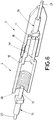
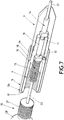
- Figures 6 to 8 show longitudinal sectional views of the optical fibre connection device 1 in which the ferrules 11, 12 and the elastic element 13 can be appreciated.
- the input optical fiber 21 end is received by the inner ferrule 11, and the output optical fiber 22 end is received by the outer ferrule 12.
- the inner and the outer ferrules 11, 12 each have inclined basis (no transversal) to provide an inclined connection plane between thereof.
- This ferrule configuration helps to further reduce the insertion losses.
- both ferrules 11, 12 are consecutively disposed along the inner end 4a of the second connection element 4, providing this way a tight connection between the input and output optical fibers 21, 22.
- the optical fibre connection device 1 further comprises an inner connector 14 having a tubular shaped configuration allocated into the inner end 3a of the first connection element 3 to provide a tight connection between the input optical fiber 21 end and the inner ferrule 11, and an outer connector 15 having a tubular shaped configuration allocated into the outer end 4b of the second connection element 4 to provide a tight connection between the output optical fiber end 22 and the outer ferrule 12.
- a tubular sheath 16 can be coaxially disposed around the inner 11 and the outer ferrule 12 to further protect the input and output optical fibers 21, 22 connection.
- the optical fibre connection device 1 can be configured to ensure that the fibers connection occurs at a desired position.
- the second connection element 4 may have a shoulder 18 between the inner and the outer end 4a, 4b, and contacting the outer end 3b of the first connection element 3.
- the closure 5 has an outer end 5b with an outward projection 17 that mates with the outer end 4b of the second connection element 4, to thus close the first and second connection element 3, 4 at a desired position.
- the optical fibre connection device 1 further comprises a stopper 19 configured to be inserted into the outer end 4b of the second connection element 4 to maintain the elastic element 13 pressing the inner and outer ferrules 11, 12 together.
- the stopper 19 has a threaded outer surface 27 and an outward flared surface 28, the threaded outer surface 27 threaded with a threaded inner surface 29 provided at the outer end 4b of the second connection element 4, and the outward flared surface 28 configured to retain the first and second connection element 3, 4 at a desired position.
- the outward flared surface 28 of the stopper 19 contacts the outward projection 17 of the closure 5 to retain the first and second connection element 3, 4 at a desired position.
Landscapes
- Physics & Mathematics (AREA)
- General Physics & Mathematics (AREA)
- Optics & Photonics (AREA)
- Mechanical Coupling Of Light Guides (AREA)
- Optical Couplings Of Light Guides (AREA)
Claims (13)
- Glasfaserverbindungsvorrichtung (1) mit:einem metallischen Prisma (2), das eine ebene Basis (6) hat, um auf einer Verbundstruktur (20) aufzuliegen, wobei das Prisma (2) einen inneren Kanal (7) hat, der gegenüberliegende Seitenflächen des Prismas (2) verbindet, wobei der Kanal (7) in erste und zweite Bohrungen (8, 9) endet, wobei die erste Bohrung (8) konfiguriert ist, eine Eingangsglasfaser (21) aufzunehmen, die in der Verbundstruktur (20) eingebettet ist,einem ersten Verbindungselement (3), das eine rohrförmige Konfiguration mit inneren und äußeren Enden (3a, 3b) hat, wobei das innere Ende (3a) konfiguriert ist, in die zweite Bohrung (9) des Prismas (2) eingesetzt zu sein, um die Eingangsglasfaser (21) aufzunehmen, undeinem zweiten Verbindungselement (4), das eine rohrförmige Konfiguration mit inneren und äußeren Enden (4a, 4b) hat, wobei das innere Ende (4a) konfiguriert ist, in das erste Verbindungselement (3) eingesetzt zu sein, und das äußere Ende (4b) konfiguriert ist, eine Ausgangsglasfaser (22) aufzunehmen,wobei
das äußere Ende (3b) des ersten Verbindungselements (3) einen inneren Kasten (30) hat, der konfiguriert ist, einen äußeren Vorsprung (31) aufzunehmen, der an dem inneren Ende (4a) des zweiten Verbindungselements (4) vorgesehen ist, um eine eindeutige Position für die Verbindung der Eingangs- und Ausgangsglasfasern (21, 22) vorzusehen,und wobei
der innere Kanal (7) des Prismas (2) zwei Abschnitte (7', 7") aufweist, die verschiedenen Ausrichtungen folgen, wobei die Ausrichtungen eine schiefe Ebene bilden, um die Eingangsglasfaser (21) in Richtung der Verbindung der Eingangs- und Ausgangsglasfaser (21, 22) zu führen,und wobei die Glasfaserverbindungsvorrichtung (1) ferner aufweist:innere und äußere Hülsen (11, 12), um jeweils die Enden der Eingangs- und Ausgangsglasfasern (21, 20) aufzunehmen,wobei die inneren und äußeren Hülsen (11, 12) entlang des inneren Endes (4a) des zweiten Verbindungselements (4) aufeinanderfolgend angeordnet sind, um eine enge Verbindung zwischen der Eingangs- und der Ausgangsglasfaser (21, 22) vorzusehen, undein elastisches Element (13), das in dem äußeren Ende (4b) des zweiten Verbindungselements (4) gehalten ist und die inneren und äußeren Hülsen (11, 12) zusammendrückt, um dadurch die Eingangs- und Ausgangsglasfasern (21, 22) zu verbinden,dadurch gekennzeichnet, dass sie ferner eine Muffe (5) aufweist, die koaxial um das äußere Ende (4b, 3b) des zweiten und des ersten Verbindungselements (4, 3) herum angeordnet ist, um das erste und zweite Verbindungselement (3, 4) miteinander zu verriegeln. - Glasfaserverbindungsvorrichtung (1) nach Anspruch 1, ferner mit:einem inneren Verbindungsstück (14), das eine rohrförmige Konfiguration hat und in dem inneren Ende (3a) des ersten Verbindungselements (3) vorgesehen ist, um eine enge Verbindung zwischen dem Ende der Eingangsglasfaser (21) und der inneren Hülse (11) vorzusehen, undeinem äußeren Verbindungsstück (15), das eine rohrförmige Konfiguration hat und in dem äußeren Ende (4b) des zweiten Verbindungselements (4) bereitgestellt ist, um eine enge Verbindung zwischen dem Ende der Ausgangsglasfaser (22) und der äußeren Hülse (12) vorzusehen.
- Glasfaserverbindungsvorrichtung (1) nach einem der vorangehenden Ansprüche, ferner mit einer rohrförmigen Ummantelung (16), die koaxial um die innere (11) und die äußere Hülse (12) herum angeordnet ist.
- Glasfaserverbindungsvorrichtung (1) nach einem der vorangehenden Ansprüche, wobei die Muffe (5) ein äußeres Ende (5b) mit einem Außenvorsprung (17) hat, der mit dem äußeren Ende (4b) des zweiten Verbindungselements (4) zusammenpasst, um die ersten und zweiten Verbindungselemente (3, 4) an einer gewünschten Position zu verriegeln.
- Glasfaserverbindungsvorrichtung (1) nach einem der vorangehenden Ansprüche, wobei die Muffe (5) eine mit einem Gewinde versehene innere Fläche (26) hat, die auf eine mit einem Gewinde versehene äußere Fläche (25) aufgeschraubt ist, die an dem äußeren Ende (3b) des ersten Verbindungselements (3) vorgesehen ist.
- Glasfaserverbindungvorrichtung (1) nach einem der vorangehenden Ansprüche, wobei das zweite Verbindungselement (4) eine Schulter (18) zwischen dem inneren und dem äußeren Ende (4a, 4b) hat, wobei die Schulter (18) das äußere Ende (3b) des ersten Verbindungselements (3) kontaktiert, um das erste und das zweite Verbindungselement (3, 4) an einer gewünschten Position zu halten.
- Glasfaserverbindungsvorrichtung (1) nach einem der vorangehenden Ansprüche, ferner mit einem Anschlag (19), der konfiguriert ist, in das äußere Ende (4b) des zweiten Verbindungselements (4) eingesetzt zu sein, um das Zusammendrücken der inneren und äußeren Hülsen (11, 12) durch das elastische Element (13) aufrechtzuerhalten.
- Glasfaserverbindungvorrichtung (1) nach Anspruch 7, wobei der Anschlag (19) eine mit einem Gewinde versehene äußere Fläche (27) und eine nach außen aufgebördelte Fläche (28) hat, wobei die mit einem Gewinde versehene äußere Fläche (27) auf eine mit einem Gewinde versehene innere Fläche (29) aufgeschraubt ist, die an dem äußeren Ende (4b) des zweiten Verbindungselements (4) vorgesehen ist, und die nach außen aufgebördelte Fläche (28) konfiguriert ist, das erste und zweite Verbindungselement (3, 4) an einer gewünschten Position zu halten.
- Glasfaserverbindungsvorrichtung (1) nach Ansprüchen 4 und 8, wobei die nach außen aufgebördelte Fläche (28) des Anschlags (19) den Außenvorsprung (17) der Muffe (5) kontaktiert, um das erste und das zweite Verbindungselement (3, 4) an einer gewünschten Position zu halten.
- Glasfaserverbindungsvorrichtung (1) nach einem der vorangehenden Ansprüche, wobei der innere Kanal (7) des Prismas (2) eine mit einem Gewinde versehene innere Fläche (23) hat, die auf eine mit einem Gewinde versehene äußere Fläche (24) aufgeschraubt ist, die an dem inneren Ende (3a) des ersten Verbindungselements (3) vorgesehen ist.
- Glasfaserverbindungsvorrichtung (1) nach einem der vorangehenden Ansprüche, wobei das erste Verbindungselement (3) ein inneres Ende (3a) mit einer düsenförmigen Konfiguration hat, die mit einer trichterförmigen Konfiguration zusammenpasst, die an dem inneren Kanal (7) des Prismas (2) vorgesehen ist, um die Verbindung zwischen ihnen zu erleichtern.
- Verbundstruktur (20) für ein Fluggerät, die eine Glasfaserverbindungsvorrichtung (1) nach einem der Ansprüche 1 bis 11 und eine äußere Verbundschicht aufweist, wobei die äußere Verbundschicht auf der Glasfaserverbindungvorrichtung (1) angeordnet ist.
- Verfahren zur Herstellung einer Verbundstruktur (20) für ein Fluggerät mit den Schritten zum:Vorsehen mindestens einer Schicht eines Verbundwerkstoffs,Vorsehen einer Eingangsglasfaser (21),Vorsehen mindestens einer Schicht des Verbundwerkstoffs auf der Eingangsglasfaser (21), um eine Verbundstruktur (20) mit einer eingebetteten Eingangsglasfaser (21) vorzusehen,Vorsehen eine Glasfaserverbindungsvorrichtung (1) mit:einem metallischen Prisma (2), das eine ebene Basis (6) hat, um auf der Verbundstruktur (20) aufzuliegen, wobei das Prisma (2) einen inneren Kanal (7) hat, der gegenüberliegende Seitenflächen des Prismas (2) verbindet, wobei der Kanal (7) in erster und zweiter Bohrung (8, 9) endet, wobei die erste Bohrung (8) konfiguriert ist, eine Eingangsglasfaser (21) aufzunehmen, die in der Verbundstruktur (20) eingebettet ist,einem ersten Verbindungselement (3), das eine rohrförmige Konfiguration mit inneren und äußeren Enden (3a, 3b) hat, wobei das innere Ende (3a) konfiguriert ist, in die zweite Bohrung (9) des Prismas (2) eingesetzt zu sein, um die Eingangsglasfaser (21) aufzunehmen, undeinem zweiten Verbindungselement (4), das eine rohrförmige Konfiguration mit inneren und äußeren Enden (4a, 4b) hat, wobei das innere Ende (4a) konfiguriert ist, in das erste Verbindungselement (3) eingesetzt zu sein, und das äußere Ende (4b) konfiguriert ist, eine Ausgangsglasfaser (22) aufzunehmen,inneren und äußeren Hülsen (11, 12), um jeweils die Enden der Eingangs- und Ausgangsglasfasern (21, 22) aufzunehmen,einem elastischen Element (13), das in dem äußeren Ende (4b) des zweiten Verbindungselements (4) gehalten ist und die innere und äußere Hülse (11, 12) zusammendrückt, undeiner Muffe (5), die koaxial um das äußere Ende (4b, 3b) des zweiten und ersten Verbindungselements (4, 3) herum angeordnet ist, um das erste und zweite Verbindungselement (3, 4) miteinander zu verriegeln,wobei das äußere Ende (3b) des ersten Verbindungselements (3) einen inneren Kasten (30) hat, der konfiguriert ist, einen äußeren Vorsprung (31) aufzunehmen, der an dem inneren Ende (4a) des zweiten Verbindungselements (4) vorgesehen ist, um eine eindeutige Position der Verbindung der Eingangs- und Ausgangsglasfaser (21, 22) vorzusehen,wobei der innere Kanal (7) des Prismas (2) zwei Abschnitte (7', 7") aufweist, die verschiedenen Ausrichtungen folgen, wobei die Ausrichtungen eine schiefe Ebene bilden, um die Eingangsglasfaser (21) in Richtung der Verbindung der Eingangs- und Ausgangsglasfaser (21, 22) zu führen, undwobei die inneren und äußeren Hülsen (11, 12) entlang des inneren Endes (4a) des zweiten Verbindungselements (4) aufeinanderfolgend angeordnet sind, um eine enge Verbindung zwischen der Eingangs- und Ausgangsglasfaser (21, 22) vorzusehen, undVorsehen mindestens einer Schicht eines Verbundwerkstoffs auf der Glasfaserverbindungsvorrichtung (1).
Priority Applications (4)
| Application Number | Priority Date | Filing Date | Title |
|---|---|---|---|
| ES16382635T ES2810854T3 (es) | 2016-12-21 | 2016-12-21 | Dispositivo de conexión de fibra óptica para una estructura compuesta, estructura compuesta para una aeronave y procedimiento de fabricación de la misma |
| EP16382635.7A EP3339925B1 (de) | 2016-12-21 | 2016-12-21 | Glasfaserverbindungsvorrichtung für eine verbundstruktur, verbundstruktur für ein flugzeug und herstellungsverfahren dafür |
| US15/845,350 US10197744B2 (en) | 2016-12-21 | 2017-12-18 | Optical fiber connector device for a composite structure, composite structure for an aircraft, and manufacturing method thereof |
| CN201711395316.5A CN108227081B (zh) | 2016-12-21 | 2017-12-21 | 光纤连接装置、飞行器的复合结构及其制造方法 |
Applications Claiming Priority (1)
| Application Number | Priority Date | Filing Date | Title |
|---|---|---|---|
| EP16382635.7A EP3339925B1 (de) | 2016-12-21 | 2016-12-21 | Glasfaserverbindungsvorrichtung für eine verbundstruktur, verbundstruktur für ein flugzeug und herstellungsverfahren dafür |
Publications (2)
| Publication Number | Publication Date |
|---|---|
| EP3339925A1 EP3339925A1 (de) | 2018-06-27 |
| EP3339925B1 true EP3339925B1 (de) | 2020-05-06 |
Family
ID=57681513
Family Applications (1)
| Application Number | Title | Priority Date | Filing Date |
|---|---|---|---|
| EP16382635.7A Active EP3339925B1 (de) | 2016-12-21 | 2016-12-21 | Glasfaserverbindungsvorrichtung für eine verbundstruktur, verbundstruktur für ein flugzeug und herstellungsverfahren dafür |
Country Status (4)
| Country | Link |
|---|---|
| US (1) | US10197744B2 (de) |
| EP (1) | EP3339925B1 (de) |
| CN (1) | CN108227081B (de) |
| ES (1) | ES2810854T3 (de) |
Family Cites Families (7)
| Publication number | Priority date | Publication date | Assignee | Title |
|---|---|---|---|---|
| US20040017981A1 (en) * | 1997-09-11 | 2004-01-29 | Jovanovich Stevan Bogdan | Capillary valve, connector, and router |
| WO2005103786A1 (en) * | 2004-04-20 | 2005-11-03 | Deutsch Uk | Waveguide assembly and connector |
| ES2366510B1 (es) * | 2008-12-30 | 2012-09-07 | Airbus Operations, S.L. | Dispositivo de conexión de fibra óptica para estructuras de material compuesto. |
| CN201413419Y (zh) * | 2009-03-24 | 2010-02-24 | 中航光电科技股份有限公司 | 一种光缆连接器 |
| US8290332B2 (en) * | 2009-08-13 | 2012-10-16 | Commscope, Inc. Of North Carolina | Optical fiber adapter |
| US20140099061A1 (en) * | 2012-10-05 | 2014-04-10 | Corning Cable Systems Llc | Reconfigurable fiber optic cable assemblies and optical connectors |
| CN105044853B (zh) * | 2015-06-28 | 2017-08-04 | 中航光电科技股份有限公司 | 一种光纤接触件部件 |
-
2016
- 2016-12-21 EP EP16382635.7A patent/EP3339925B1/de active Active
- 2016-12-21 ES ES16382635T patent/ES2810854T3/es active Active
-
2017
- 2017-12-18 US US15/845,350 patent/US10197744B2/en active Active
- 2017-12-21 CN CN201711395316.5A patent/CN108227081B/zh active Active
Non-Patent Citations (1)
| Title |
|---|
| None * |
Also Published As
| Publication number | Publication date |
|---|---|
| US20180172921A1 (en) | 2018-06-21 |
| US10197744B2 (en) | 2019-02-05 |
| EP3339925A1 (de) | 2018-06-27 |
| CN108227081B (zh) | 2021-03-02 |
| ES2810854T3 (es) | 2021-03-09 |
| CN108227081A (zh) | 2018-06-29 |
Similar Documents
| Publication | Publication Date | Title |
|---|---|---|
| EP2241912B1 (de) | Einbaubarer optischer Faser-Verbinder und zugehöriges Herstellungsverfahren | |
| US6035084A (en) | Fiber optic connector and associated method for establishing an optical connection with an optical fiber embedded within a composite structure | |
| CN104380163B (zh) | 被加固的光纤连接器 | |
| US10088079B2 (en) | Assembly of a flexible pipe and an end-fitting | |
| US5355429A (en) | Optical fiber strain relief apparatus | |
| US20070196059A1 (en) | Tape-shaped optical fiber cable | |
| US20170336575A1 (en) | Optical interconnection component | |
| US20180196211A1 (en) | Optical fiber cord and method of manufacturing optical fiber cord | |
| CN109073831B (zh) | 光纤保护构造以及光学元件的制造方法 | |
| CN105928468A (zh) | 一种光纤光栅应变传感器及其制作方法 | |
| US9664864B2 (en) | Method for terminating high fiber count cables | |
| US20090034916A1 (en) | Fiber optic cable with in-line fiber optic splice | |
| US12013579B1 (en) | Optical interconnect devices | |
| EP3339925B1 (de) | Glasfaserverbindungsvorrichtung für eine verbundstruktur, verbundstruktur für ein flugzeug und herstellungsverfahren dafür | |
| CN213122391U (zh) | 一种光纤编码光纤护套结构及松套尾纤 | |
| US9964711B1 (en) | Optical cable for avionics applications, method of manufacture thereof and articles comprising the same | |
| US8781280B2 (en) | Cable expansion joint | |
| JP2013213934A (ja) | 光接続部材及び光接続部材の製造方法 | |
| JP4946338B2 (ja) | 構造物敷設用テープ状光ファイバ及びその製造方法 | |
| EP0890856A1 (de) | Optischer Koppler | |
| Davidson et al. | Composite materials monitoring through embedded fibre optics | |
| KR20240087345A (ko) | 광섬유 케이블 커넥터 | |
| US8870473B2 (en) | Method of terminating a fiber optic cable | |
| GB2505736A (en) | Method of incorporating a coil of optical fibre into a composite structure | |
| Lisi | Metal-Coated Fibers |
Legal Events
| Date | Code | Title | Description |
|---|---|---|---|
| PUAI | Public reference made under article 153(3) epc to a published international application that has entered the european phase |
Free format text: ORIGINAL CODE: 0009012 |
|
| STAA | Information on the status of an ep patent application or granted ep patent |
Free format text: STATUS: THE APPLICATION HAS BEEN PUBLISHED |
|
| AK | Designated contracting states |
Kind code of ref document: A1 Designated state(s): AL AT BE BG CH CY CZ DE DK EE ES FI FR GB GR HR HU IE IS IT LI LT LU LV MC MK MT NL NO PL PT RO RS SE SI SK SM TR |
|
| AX | Request for extension of the european patent |
Extension state: BA ME |
|
| STAA | Information on the status of an ep patent application or granted ep patent |
Free format text: STATUS: REQUEST FOR EXAMINATION WAS MADE |
|
| 17P | Request for examination filed |
Effective date: 20181213 |
|
| RBV | Designated contracting states (corrected) |
Designated state(s): AL AT BE BG CH CY CZ DE DK EE ES FI FR GB GR HR HU IE IS IT LI LT LU LV MC MK MT NL NO PL PT RO RS SE SI SK SM TR |
|
| GRAP | Despatch of communication of intention to grant a patent |
Free format text: ORIGINAL CODE: EPIDOSNIGR1 |
|
| STAA | Information on the status of an ep patent application or granted ep patent |
Free format text: STATUS: GRANT OF PATENT IS INTENDED |
|
| GRAS | Grant fee paid |
Free format text: ORIGINAL CODE: EPIDOSNIGR3 |
|
| GRAA | (expected) grant |
Free format text: ORIGINAL CODE: 0009210 |
|
| STAA | Information on the status of an ep patent application or granted ep patent |
Free format text: STATUS: THE PATENT HAS BEEN GRANTED |
|
| INTG | Intention to grant announced |
Effective date: 20200316 |
|
| AK | Designated contracting states |
Kind code of ref document: B1 Designated state(s): AL AT BE BG CH CY CZ DE DK EE ES FI FR GB GR HR HU IE IS IT LI LT LU LV MC MK MT NL NO PL PT RO RS SE SI SK SM TR |
|
| REG | Reference to a national code |
Ref country code: GB Ref legal event code: FG4D |
|
| REG | Reference to a national code |
Ref country code: AT Ref legal event code: REF Ref document number: 1267692 Country of ref document: AT Kind code of ref document: T Effective date: 20200515 Ref country code: CH Ref legal event code: EP |
|
| REG | Reference to a national code |
Ref country code: IE Ref legal event code: FG4D |
|
| REG | Reference to a national code |
Ref country code: DE Ref legal event code: R096 Ref document number: 602016035654 Country of ref document: DE |
|
| REG | Reference to a national code |
Ref country code: LT Ref legal event code: MG4D |
|
| REG | Reference to a national code |
Ref country code: NL Ref legal event code: MP Effective date: 20200506 |
|
| PG25 | Lapsed in a contracting state [announced via postgrant information from national office to epo] |
Ref country code: PT Free format text: LAPSE BECAUSE OF FAILURE TO SUBMIT A TRANSLATION OF THE DESCRIPTION OR TO PAY THE FEE WITHIN THE PRESCRIBED TIME-LIMIT Effective date: 20200907 Ref country code: SE Free format text: LAPSE BECAUSE OF FAILURE TO SUBMIT A TRANSLATION OF THE DESCRIPTION OR TO PAY THE FEE WITHIN THE PRESCRIBED TIME-LIMIT Effective date: 20200506 Ref country code: LT Free format text: LAPSE BECAUSE OF FAILURE TO SUBMIT A TRANSLATION OF THE DESCRIPTION OR TO PAY THE FEE WITHIN THE PRESCRIBED TIME-LIMIT Effective date: 20200506 Ref country code: IS Free format text: LAPSE BECAUSE OF FAILURE TO SUBMIT A TRANSLATION OF THE DESCRIPTION OR TO PAY THE FEE WITHIN THE PRESCRIBED TIME-LIMIT Effective date: 20200906 Ref country code: GR Free format text: LAPSE BECAUSE OF FAILURE TO SUBMIT A TRANSLATION OF THE DESCRIPTION OR TO PAY THE FEE WITHIN THE PRESCRIBED TIME-LIMIT Effective date: 20200807 Ref country code: NO Free format text: LAPSE BECAUSE OF FAILURE TO SUBMIT A TRANSLATION OF THE DESCRIPTION OR TO PAY THE FEE WITHIN THE PRESCRIBED TIME-LIMIT Effective date: 20200806 Ref country code: FI Free format text: LAPSE BECAUSE OF FAILURE TO SUBMIT A TRANSLATION OF THE DESCRIPTION OR TO PAY THE FEE WITHIN THE PRESCRIBED TIME-LIMIT Effective date: 20200506 |
|
| PG25 | Lapsed in a contracting state [announced via postgrant information from national office to epo] |
Ref country code: BG Free format text: LAPSE BECAUSE OF FAILURE TO SUBMIT A TRANSLATION OF THE DESCRIPTION OR TO PAY THE FEE WITHIN THE PRESCRIBED TIME-LIMIT Effective date: 20200806 Ref country code: RS Free format text: LAPSE BECAUSE OF FAILURE TO SUBMIT A TRANSLATION OF THE DESCRIPTION OR TO PAY THE FEE WITHIN THE PRESCRIBED TIME-LIMIT Effective date: 20200506 Ref country code: HR Free format text: LAPSE BECAUSE OF FAILURE TO SUBMIT A TRANSLATION OF THE DESCRIPTION OR TO PAY THE FEE WITHIN THE PRESCRIBED TIME-LIMIT Effective date: 20200506 Ref country code: LV Free format text: LAPSE BECAUSE OF FAILURE TO SUBMIT A TRANSLATION OF THE DESCRIPTION OR TO PAY THE FEE WITHIN THE PRESCRIBED TIME-LIMIT Effective date: 20200506 |
|
| REG | Reference to a national code |
Ref country code: AT Ref legal event code: MK05 Ref document number: 1267692 Country of ref document: AT Kind code of ref document: T Effective date: 20200506 |
|
| PG25 | Lapsed in a contracting state [announced via postgrant information from national office to epo] |
Ref country code: AL Free format text: LAPSE BECAUSE OF FAILURE TO SUBMIT A TRANSLATION OF THE DESCRIPTION OR TO PAY THE FEE WITHIN THE PRESCRIBED TIME-LIMIT Effective date: 20200506 Ref country code: NL Free format text: LAPSE BECAUSE OF FAILURE TO SUBMIT A TRANSLATION OF THE DESCRIPTION OR TO PAY THE FEE WITHIN THE PRESCRIBED TIME-LIMIT Effective date: 20200506 |
|
| PG25 | Lapsed in a contracting state [announced via postgrant information from national office to epo] |
Ref country code: AT Free format text: LAPSE BECAUSE OF FAILURE TO SUBMIT A TRANSLATION OF THE DESCRIPTION OR TO PAY THE FEE WITHIN THE PRESCRIBED TIME-LIMIT Effective date: 20200506 Ref country code: EE Free format text: LAPSE BECAUSE OF FAILURE TO SUBMIT A TRANSLATION OF THE DESCRIPTION OR TO PAY THE FEE WITHIN THE PRESCRIBED TIME-LIMIT Effective date: 20200506 Ref country code: IT Free format text: LAPSE BECAUSE OF FAILURE TO SUBMIT A TRANSLATION OF THE DESCRIPTION OR TO PAY THE FEE WITHIN THE PRESCRIBED TIME-LIMIT Effective date: 20200506 Ref country code: SM Free format text: LAPSE BECAUSE OF FAILURE TO SUBMIT A TRANSLATION OF THE DESCRIPTION OR TO PAY THE FEE WITHIN THE PRESCRIBED TIME-LIMIT Effective date: 20200506 Ref country code: DK Free format text: LAPSE BECAUSE OF FAILURE TO SUBMIT A TRANSLATION OF THE DESCRIPTION OR TO PAY THE FEE WITHIN THE PRESCRIBED TIME-LIMIT Effective date: 20200506 Ref country code: CZ Free format text: LAPSE BECAUSE OF FAILURE TO SUBMIT A TRANSLATION OF THE DESCRIPTION OR TO PAY THE FEE WITHIN THE PRESCRIBED TIME-LIMIT Effective date: 20200506 Ref country code: RO Free format text: LAPSE BECAUSE OF FAILURE TO SUBMIT A TRANSLATION OF THE DESCRIPTION OR TO PAY THE FEE WITHIN THE PRESCRIBED TIME-LIMIT Effective date: 20200506 |
|
| REG | Reference to a national code |
Ref country code: DE Ref legal event code: R097 Ref document number: 602016035654 Country of ref document: DE |
|
| PG25 | Lapsed in a contracting state [announced via postgrant information from national office to epo] |
Ref country code: SK Free format text: LAPSE BECAUSE OF FAILURE TO SUBMIT A TRANSLATION OF THE DESCRIPTION OR TO PAY THE FEE WITHIN THE PRESCRIBED TIME-LIMIT Effective date: 20200506 Ref country code: PL Free format text: LAPSE BECAUSE OF FAILURE TO SUBMIT A TRANSLATION OF THE DESCRIPTION OR TO PAY THE FEE WITHIN THE PRESCRIBED TIME-LIMIT Effective date: 20200506 |
|
| REG | Reference to a national code |
Ref country code: ES Ref legal event code: FG2A Ref document number: 2810854 Country of ref document: ES Kind code of ref document: T3 Effective date: 20210309 |
|
| PLBE | No opposition filed within time limit |
Free format text: ORIGINAL CODE: 0009261 |
|
| STAA | Information on the status of an ep patent application or granted ep patent |
Free format text: STATUS: NO OPPOSITION FILED WITHIN TIME LIMIT |
|
| 26N | No opposition filed |
Effective date: 20210209 |
|
| PG25 | Lapsed in a contracting state [announced via postgrant information from national office to epo] |
Ref country code: SI Free format text: LAPSE BECAUSE OF FAILURE TO SUBMIT A TRANSLATION OF THE DESCRIPTION OR TO PAY THE FEE WITHIN THE PRESCRIBED TIME-LIMIT Effective date: 20200506 |
|
| REG | Reference to a national code |
Ref country code: CH Ref legal event code: PL |
|
| PG25 | Lapsed in a contracting state [announced via postgrant information from national office to epo] |
Ref country code: MC Free format text: LAPSE BECAUSE OF FAILURE TO SUBMIT A TRANSLATION OF THE DESCRIPTION OR TO PAY THE FEE WITHIN THE PRESCRIBED TIME-LIMIT Effective date: 20200506 |
|
| REG | Reference to a national code |
Ref country code: BE Ref legal event code: MM Effective date: 20201231 |
|
| PG25 | Lapsed in a contracting state [announced via postgrant information from national office to epo] |
Ref country code: IE Free format text: LAPSE BECAUSE OF NON-PAYMENT OF DUE FEES Effective date: 20201221 Ref country code: LU Free format text: LAPSE BECAUSE OF NON-PAYMENT OF DUE FEES Effective date: 20201221 |
|
| PG25 | Lapsed in a contracting state [announced via postgrant information from national office to epo] |
Ref country code: CH Free format text: LAPSE BECAUSE OF NON-PAYMENT OF DUE FEES Effective date: 20201231 Ref country code: LI Free format text: LAPSE BECAUSE OF NON-PAYMENT OF DUE FEES Effective date: 20201231 |
|
| PG25 | Lapsed in a contracting state [announced via postgrant information from national office to epo] |
Ref country code: TR Free format text: LAPSE BECAUSE OF FAILURE TO SUBMIT A TRANSLATION OF THE DESCRIPTION OR TO PAY THE FEE WITHIN THE PRESCRIBED TIME-LIMIT Effective date: 20200506 Ref country code: MT Free format text: LAPSE BECAUSE OF FAILURE TO SUBMIT A TRANSLATION OF THE DESCRIPTION OR TO PAY THE FEE WITHIN THE PRESCRIBED TIME-LIMIT Effective date: 20200506 Ref country code: CY Free format text: LAPSE BECAUSE OF FAILURE TO SUBMIT A TRANSLATION OF THE DESCRIPTION OR TO PAY THE FEE WITHIN THE PRESCRIBED TIME-LIMIT Effective date: 20200506 |
|
| PG25 | Lapsed in a contracting state [announced via postgrant information from national office to epo] |
Ref country code: MK Free format text: LAPSE BECAUSE OF FAILURE TO SUBMIT A TRANSLATION OF THE DESCRIPTION OR TO PAY THE FEE WITHIN THE PRESCRIBED TIME-LIMIT Effective date: 20200506 |
|
| PG25 | Lapsed in a contracting state [announced via postgrant information from national office to epo] |
Ref country code: BE Free format text: LAPSE BECAUSE OF NON-PAYMENT OF DUE FEES Effective date: 20201231 |
|
| PGFP | Annual fee paid to national office [announced via postgrant information from national office to epo] |
Ref country code: DE Payment date: 20251211 Year of fee payment: 10 |
|
| PGFP | Annual fee paid to national office [announced via postgrant information from national office to epo] |
Ref country code: GB Payment date: 20251219 Year of fee payment: 10 |
|
| PGFP | Annual fee paid to national office [announced via postgrant information from national office to epo] |
Ref country code: FR Payment date: 20251229 Year of fee payment: 10 |
|
| PGFP | Annual fee paid to national office [announced via postgrant information from national office to epo] |
Ref country code: ES Payment date: 20260130 Year of fee payment: 10 |