EP3339772B1 - Kondensator und kühlschrank damit - Google Patents
Kondensator und kühlschrank damit Download PDFInfo
- Publication number
- EP3339772B1 EP3339772B1 EP16899083.6A EP16899083A EP3339772B1 EP 3339772 B1 EP3339772 B1 EP 3339772B1 EP 16899083 A EP16899083 A EP 16899083A EP 3339772 B1 EP3339772 B1 EP 3339772B1
- Authority
- EP
- European Patent Office
- Prior art keywords
- condensation pipe
- condenser
- condensation
- pipe segment
- pipe segments
- Prior art date
- Legal status (The legal status is an assumption and is not a legal conclusion. Google has not performed a legal analysis and makes no representation as to the accuracy of the status listed.)
- Active
Links
Images


Classifications
-
- F—MECHANICAL ENGINEERING; LIGHTING; HEATING; WEAPONS; BLASTING
- F25—REFRIGERATION OR COOLING; COMBINED HEATING AND REFRIGERATION SYSTEMS; HEAT PUMP SYSTEMS; MANUFACTURE OR STORAGE OF ICE; LIQUEFACTION SOLIDIFICATION OF GASES
- F25D—REFRIGERATORS; COLD ROOMS; ICE-BOXES; COOLING OR FREEZING APPARATUS NOT OTHERWISE PROVIDED FOR
- F25D23/00—General constructional features
- F25D23/003—General constructional features for cooling refrigerating machinery
-
- F—MECHANICAL ENGINEERING; LIGHTING; HEATING; WEAPONS; BLASTING
- F28—HEAT EXCHANGE IN GENERAL
- F28D—HEAT-EXCHANGE APPARATUS, NOT PROVIDED FOR IN ANOTHER SUBCLASS, IN WHICH THE HEAT-EXCHANGE MEDIA DO NOT COME INTO DIRECT CONTACT
- F28D1/00—Heat-exchange apparatus having stationary conduit assemblies for one heat-exchange medium only, the media being in contact with different sides of the conduit wall, in which the other heat-exchange medium is a large body of fluid, e.g. domestic or motor car radiators
- F28D1/02—Heat-exchange apparatus having stationary conduit assemblies for one heat-exchange medium only, the media being in contact with different sides of the conduit wall, in which the other heat-exchange medium is a large body of fluid, e.g. domestic or motor car radiators with heat-exchange conduits immersed in the body of fluid
- F28D1/04—Heat-exchange apparatus having stationary conduit assemblies for one heat-exchange medium only, the media being in contact with different sides of the conduit wall, in which the other heat-exchange medium is a large body of fluid, e.g. domestic or motor car radiators with heat-exchange conduits immersed in the body of fluid with tubular conduits
- F28D1/047—Heat-exchange apparatus having stationary conduit assemblies for one heat-exchange medium only, the media being in contact with different sides of the conduit wall, in which the other heat-exchange medium is a large body of fluid, e.g. domestic or motor car radiators with heat-exchange conduits immersed in the body of fluid with tubular conduits the conduits being bent, e.g. in a serpentine or zig-zag
- F28D1/0472—Heat-exchange apparatus having stationary conduit assemblies for one heat-exchange medium only, the media being in contact with different sides of the conduit wall, in which the other heat-exchange medium is a large body of fluid, e.g. domestic or motor car radiators with heat-exchange conduits immersed in the body of fluid with tubular conduits the conduits being bent, e.g. in a serpentine or zig-zag the conduits being helically or spirally coiled
-
- F—MECHANICAL ENGINEERING; LIGHTING; HEATING; WEAPONS; BLASTING
- F25—REFRIGERATION OR COOLING; COMBINED HEATING AND REFRIGERATION SYSTEMS; HEAT PUMP SYSTEMS; MANUFACTURE OR STORAGE OF ICE; LIQUEFACTION SOLIDIFICATION OF GASES
- F25B—REFRIGERATION MACHINES, PLANTS OR SYSTEMS; COMBINED HEATING AND REFRIGERATION SYSTEMS; HEAT PUMP SYSTEMS
- F25B39/00—Evaporators; Condensers
- F25B39/04—Condensers
-
- F—MECHANICAL ENGINEERING; LIGHTING; HEATING; WEAPONS; BLASTING
- F25—REFRIGERATION OR COOLING; COMBINED HEATING AND REFRIGERATION SYSTEMS; HEAT PUMP SYSTEMS; MANUFACTURE OR STORAGE OF ICE; LIQUEFACTION SOLIDIFICATION OF GASES
- F25D—REFRIGERATORS; COLD ROOMS; ICE-BOXES; COOLING OR FREEZING APPARATUS NOT OTHERWISE PROVIDED FOR
- F25D11/00—Self-contained movable devices, e.g. domestic refrigerators
-
- F—MECHANICAL ENGINEERING; LIGHTING; HEATING; WEAPONS; BLASTING
- F25—REFRIGERATION OR COOLING; COMBINED HEATING AND REFRIGERATION SYSTEMS; HEAT PUMP SYSTEMS; MANUFACTURE OR STORAGE OF ICE; LIQUEFACTION SOLIDIFICATION OF GASES
- F25D—REFRIGERATORS; COLD ROOMS; ICE-BOXES; COOLING OR FREEZING APPARATUS NOT OTHERWISE PROVIDED FOR
- F25D17/00—Arrangements for circulating cooling fluids; Arrangements for circulating gas, e.g. air, within refrigerated spaces
- F25D17/04—Arrangements for circulating cooling fluids; Arrangements for circulating gas, e.g. air, within refrigerated spaces for circulating air, e.g. by convection
- F25D17/06—Arrangements for circulating cooling fluids; Arrangements for circulating gas, e.g. air, within refrigerated spaces for circulating air, e.g. by convection by forced circulation
- F25D17/062—Arrangements for circulating cooling fluids; Arrangements for circulating gas, e.g. air, within refrigerated spaces for circulating air, e.g. by convection by forced circulation in household refrigerators
-
- F—MECHANICAL ENGINEERING; LIGHTING; HEATING; WEAPONS; BLASTING
- F25—REFRIGERATION OR COOLING; COMBINED HEATING AND REFRIGERATION SYSTEMS; HEAT PUMP SYSTEMS; MANUFACTURE OR STORAGE OF ICE; LIQUEFACTION SOLIDIFICATION OF GASES
- F25D—REFRIGERATORS; COLD ROOMS; ICE-BOXES; COOLING OR FREEZING APPARATUS NOT OTHERWISE PROVIDED FOR
- F25D19/00—Arrangement or mounting of refrigeration units with respect to devices or objects to be refrigerated, e.g. infrared detectors
-
- F—MECHANICAL ENGINEERING; LIGHTING; HEATING; WEAPONS; BLASTING
- F28—HEAT EXCHANGE IN GENERAL
- F28B—STEAM OR VAPOUR CONDENSERS
- F28B1/00—Condensers in which the steam or vapour is separate from the cooling medium by walls, e.g. surface condenser
- F28B1/06—Condensers in which the steam or vapour is separate from the cooling medium by walls, e.g. surface condenser using air or other gas as the cooling medium
-
- F—MECHANICAL ENGINEERING; LIGHTING; HEATING; WEAPONS; BLASTING
- F28—HEAT EXCHANGE IN GENERAL
- F28D—HEAT-EXCHANGE APPARATUS, NOT PROVIDED FOR IN ANOTHER SUBCLASS, IN WHICH THE HEAT-EXCHANGE MEDIA DO NOT COME INTO DIRECT CONTACT
- F28D1/00—Heat-exchange apparatus having stationary conduit assemblies for one heat-exchange medium only, the media being in contact with different sides of the conduit wall, in which the other heat-exchange medium is a large body of fluid, e.g. domestic or motor car radiators
- F28D1/02—Heat-exchange apparatus having stationary conduit assemblies for one heat-exchange medium only, the media being in contact with different sides of the conduit wall, in which the other heat-exchange medium is a large body of fluid, e.g. domestic or motor car radiators with heat-exchange conduits immersed in the body of fluid
- F28D1/0233—Heat-exchange apparatus having stationary conduit assemblies for one heat-exchange medium only, the media being in contact with different sides of the conduit wall, in which the other heat-exchange medium is a large body of fluid, e.g. domestic or motor car radiators with heat-exchange conduits immersed in the body of fluid with air flow channels
- F28D1/024—Heat-exchange apparatus having stationary conduit assemblies for one heat-exchange medium only, the media being in contact with different sides of the conduit wall, in which the other heat-exchange medium is a large body of fluid, e.g. domestic or motor car radiators with heat-exchange conduits immersed in the body of fluid with air flow channels with an air driving element
-
- F—MECHANICAL ENGINEERING; LIGHTING; HEATING; WEAPONS; BLASTING
- F28—HEAT EXCHANGE IN GENERAL
- F28D—HEAT-EXCHANGE APPARATUS, NOT PROVIDED FOR IN ANOTHER SUBCLASS, IN WHICH THE HEAT-EXCHANGE MEDIA DO NOT COME INTO DIRECT CONTACT
- F28D7/00—Heat-exchange apparatus having stationary tubular conduit assemblies for both heat-exchange media, the media being in contact with different sides of a conduit wall
- F28D7/02—Heat-exchange apparatus having stationary tubular conduit assemblies for both heat-exchange media, the media being in contact with different sides of a conduit wall the conduits being helically coiled
- F28D7/024—Heat-exchange apparatus having stationary tubular conduit assemblies for both heat-exchange media, the media being in contact with different sides of a conduit wall the conduits being helically coiled the conduits of only one medium being helically coiled tubes, the coils having a cylindrical configuration
-
- F—MECHANICAL ENGINEERING; LIGHTING; HEATING; WEAPONS; BLASTING
- F25—REFRIGERATION OR COOLING; COMBINED HEATING AND REFRIGERATION SYSTEMS; HEAT PUMP SYSTEMS; MANUFACTURE OR STORAGE OF ICE; LIQUEFACTION SOLIDIFICATION OF GASES
- F25B—REFRIGERATION MACHINES, PLANTS OR SYSTEMS; COMBINED HEATING AND REFRIGERATION SYSTEMS; HEAT PUMP SYSTEMS
- F25B2339/00—Details of evaporators; Details of condensers
- F25B2339/04—Details of condensers
-
- F—MECHANICAL ENGINEERING; LIGHTING; HEATING; WEAPONS; BLASTING
- F28—HEAT EXCHANGE IN GENERAL
- F28D—HEAT-EXCHANGE APPARATUS, NOT PROVIDED FOR IN ANOTHER SUBCLASS, IN WHICH THE HEAT-EXCHANGE MEDIA DO NOT COME INTO DIRECT CONTACT
- F28D21/00—Heat-exchange apparatus not covered by any of the groups F28D1/00 - F28D20/00
- F28D2021/0019—Other heat exchangers for particular applications; Heat exchange systems not otherwise provided for
- F28D2021/0068—Other heat exchangers for particular applications; Heat exchange systems not otherwise provided for for refrigerant cycles
- F28D2021/007—Condensers
Definitions
- the present disclosure relates to a technical field of refrigeration, and specifically to a condenser and a refrigerator having the same.
- a refrigeration system for a refrigerator generally uses condensers in the following two structures to perform heat dissipation.
- a refrigerator with a heat exchanger according to the preamble of claim 1 is also decreased described in KR 2008 0101356 A , where the air volume, which is exchanged with a condenser, is increased by having it flow through a duct.
- the refrigerator is thus composed of a duct placed in the machine room, a condenser and a pipeline through the duct and condenser, which passes through the heat exchange fin.
- the hot water heat energy recovery device comprises a bucket, provided with a waste hot water inflow connector, and a heat energy recovery pipe in the bucket.
- the water inlet and water outlet connector of the pipe is arranged on the side wall of the bucket and the bucket comprises a cold wastewater discharge port.
- the recovery device itself does not need to be driven by any energy, thereby being capable of saving energy.
- the document 102 927 745 A discloses a refrigerator forced heat radiation structure which comprises a refrigerator main body, a compressor chamber with the rear cover plate, wherein a compressor, a heat radiation fan and a condenser are sequentially arranged inside the compressor chamber.
- Two ends of the rear cover plate are respectively provided with an air inlet and an air outlet and the air inlet end of the condenser corresponds to the air inlet of the rear cover plate and the air outlet of the rear cover plate corresponds to the compressor.
- a circular air duct favoring the heat radiation of the condenser is formed through the reasonable arrangement of all components and the heat radiation structure of a refrigerator, and airflow can uniformly and efficiently pass through the condenser through the running of the fan, so that the heat radiation of the condenser is accelerated, and the power consumption of the refrigerator is reduced.
- a refrigerating system for an ice chest is described in CN 102 494 469 A , where the refrigerating system comprises an air for new component, the first condenser, second condenser, first compressor, second compressor and a fan, wherein the air flue component is provided with an air inlet and an air outlet and the first condenser and the second condenser are arranged at an interval and the airflow with the air outlet in the middle of both and the first compressor and the second compressor are arranged at an interval and adjacent to the first condenser and the second condenser respectively.
- the fan is arranged at the air outlet to blow air to the first condenser and the second condenser simultaneously.
- a condenser component for refrigerator and a refrigerator comprises a condenser, a centrifugal fan and a vent channel.
- An air inlet of the centrifugal fan is opposite to the condenser and and an air inlet of the vent channel is connected with an air outlet of the first centrifugal fan and the air outlet of the vent channel is suitable for stretching out of the compressor warehouse of the refrigerator.
- the condenser component has the advantage of being high and heat exchange efficiency and low and energy consumption and noise.
- CN 202 158 706 U discloses a refrigerator capable of increasing the heating mission performance.
- the fridge refrigerator comprises a machine chamber provided with a compressor, a front wall for separating the forward machine chamber from a backward refrigerating chamber, a pipeline arranged in the machine chamber and formed along the front wall, wherein an air outlet is opened on the upper part in the suction port of the air inlet is opened on the lower part, a condenser housed in the pipeline and the blowing fan for transferring the air from the pipeline to the compressor.
- CN 202 133 219 U discloses a condenser structure of record storage cabinet comprising a condenser provided with a fan.
- the condenser is arranged in a duct seat and a duct cover is arranged on a duct seat.
- the side of the duct seat is provided with a duct inlet for installing the fan and the duct cover is provided with a duct outlet in the duct is formed between the duct Inlet and the duct outlet.
- the condenser structure of the cold storage cabinet has the advantage of being simple in structure and good and radiation effect.
- a refrigerator is disclosed in the document JP 2012 255 638 A and comprises a machine room provided at the back face the wall part of a cabinet, a front wall of the machine room separating the machine room and a refrigerant room back and forth, duct provided in the machine room along the front wall of the machine room to section air from a lower part of the machine room, a condenser provided in the duct and the radiation fan provided at the back of the duct in the machine room.
- the condenser includes a refrigerant tube in which the refrigerant flows and radiation fin provided with the refrigerant tube.
- the present disclosure seeks to solve one of the technical problems existing in the related art to at least some extent. For that reason, the present disclosure provides a condenser, which has good heat dissipation effect and a reasonable and compact arrangement.
- the present disclosure also provides a refrigerator having the condenser.
- the condenser includes: an air duct defining an air channel therein; an air supply device fixedly connected with the air duct; and a condensation member having a refrigerant inlet and a refrigerant outlet, the condensation member being at least partly disposed in the air channel.
- the condenser according to embodiments of a first aspect of the present disclosure not only has a good heat dissipation effect, but also has a compact and reasonable arrangement, and further has better versatility.
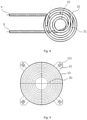
- the condensation member includes a plurality of first condensation pipe segments successively arranged in an axial direction of the air duct and communicated with each other, each of the first condensation pipe segments is helically formed by a first condensation pipe, and a helical line of each of the first condensation pipe segments is located in a same ring surface.
- the condensation member also includes a second condensation pipe segment communicated with at least one of the plurality of first condensation pipe segments, the second condensation pipe segment being located in an inner side of the plurality of first condensation pipe segments.
- the second condensation pipe segment is formed by a second condensation pipe helically encircling a center axis of the air duct.
- each of the first condensation pipe segments has an inner side located in a same inner circular ring and an outer side located in a same outer circular ring, the inner circular rings of the plurality of first condensation pipe segments are arranged coaxially and the outer circular rings of the plurality of first condensation pipe segments are arranged coaxially.
- encircling centers of two adjacent first condensation pipe segments are coaxially provided and the encircling centers of the two adjacent first condensation pipe segments have different diameters; when the number of the first condensation pipe segments is equal to or more than two, the encircling center of each first condensation pipe segment and the encircling center of the sub-adjacent first condensation pipe segment have the same diameter.
- an inner diameter of the air duct is larger than a diameter of the outer circular ring.
- the second condensation pipe segment and the plurality of first condensation pipe segments are successively connected, the refrigerant inlet is defined in the second condensation pipe segment and the refrigerant outlet is defined in one of the plurality of first condensation pipe segments, or the refrigerant outlet is defined in the second condensation pipe segment and the refrigerant inlet is defined in one of the plurality of first condensation pipe segments.
- an upper end of the second condensation pipe segment is connected with the uppermost first condensation pipe segment, the first condensation pipe segment located above is connected with the adjacent first condensation pipe segment located below, the refrigerant inlet is defined in one of the second condensation pipe segment and the lowermost first condensation pipe segment, and the refrigerant outlet is defined in the other one of the second condensation pipe segment and the lowermost first condensation pipe segment.
- the condensation member includes a plurality of third condensation pipe segments successively arranged from outside to inside, two adjacent third condensation pipe segments are communicated with each other, and each of the third condensation pipe segments is formed by a third condensation pipe helically encircling the center axis of the air duct.
- a helical line of each of the third condensation pipe segments is substantially located in a same cylindrical surface, when the number of the third condensation pipe segments is equal to or more than two, a difference value between diameters of the cylindrical surfaces where the helical lines of two adjacent third condensation pipe segments is a constant value.
- a helical line of each of the third condensation pipe segments is substantially located in a same conical surface, the helical line of each of the third condensation pipe segments gradually extends inwards from up to down, an inner diameter of the air duct is gradually reduced from up to down, and a gap is provided between the air duct and an outermost third condensation pipe segment.
- an inlet and an outlet of each of the third condensation pipe segments are defined at an uppermost end and at a lowermost end respectively; in two adjacent third condensation pipe segments, the inlet of one third condensation pipe segment is aligned and communicated with the outlet of the other third condensation pipe segment.
- the refrigerant inlet and the refrigerant outlet extend out of the air duct through a through hole located at a bottom of the air duct.
- the refrigerator according to embodiments of a second aspect of the present disclosure includes the condenser.
- the refrigerator has a compressor room for at least containing a compressor, and an air supply device is fixed in the compressor room through a mounting support.
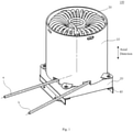
- condenser 100 air duct 10, air channel 11, bottom foot 12, mounting hole 121, through hole 13, air supply device 20, condensation member 30, refrigerant inlet a , refrigerant outlet b , first condensation pipe segment 31, inner circular ring 311, outer circular ring 312, encircling center 313, second condensation pipe segment 32, third condensation pipe segment 33, mounting support 20.
- a condenser 100 according to embodiments of the present disclosure will be described with reference to Figs. 1-14 in detail in the following.
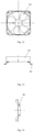
- the condenser 100 includes an air duct 10, an air supply device 20 and a condensation member 30.
- the air duct 10 defines an air channel 11 therein, the air supply device 20 is fixedly connected with the air duct 10, the condensation member 30 has a refrigerant inlet a and a refrigerant outlet b, and the condensation member 30 is at least partly disposed in the air channel 11.
- the air supply device 20 is used to perform forced ventilation to the air channel 11, such that ambient air can regularly enter the air channel 11 and exchange heat with the condensation member 30 in the air channel 11, thereby facilitating a quick and even heat dissipation of the condensation member 30, significantly enhancing the heat dissipation effect of the condenser 100; moreover, the overall arrangement of the condenser 100 can be more compact and reasonable and the condenser 100 can be applicable to various kinds of refrigerators.
- the refrigerant inlet a is used for introducing in a gas refrigerant at high temperature and high pressure.
- the gas refrigerant flows through the condensation member 30 and dissipates heat to the ambient air, so as to be transformed into a liquid refrigerant and flow out of the refrigerant outlet b .
- the air supply device 20 can be a fan, and two ends of the air duct 10 are both open, so as to allow the ambient air to enter in or flow out of the air channel 11 under the action of the air supply device 20.
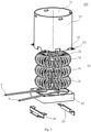
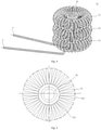
- the condensation member 30 includes a plurality of first condensation pipe segments 31 successively arranged in an axial direction of the air duct 10 and communicated with each other.
- Each of the first condensation pipe segments 31 is helically formed by a first condensation pipe, and a helical line of each of the first condensation pipe segments 31 is located in a same ring surface.
- the ring surface refers to a rotary surface formed by a circle or an ellipse completing one revolution around a straight line, in which the straight line does not intersect with the circle or ellipse.
- the helical line of the first condensation pipe segment 31 is a helical track line of the first condensation pipe.
- the ring surfaces where the plurality of first condensation pipe segments 31 is located are arranged successively in the air channel 11 from an end of the air duct 10 to the other end of the air duct 10.
- Each of the first condensation pipe segments 31 is communicated with at least one of the rest of the first condensation pipe segments 31, so as to allow the refrigerant to flow through each of the first condensation pipe segments 31.
- the helical line of each of the first condensation pipe segments 31 is located in the same ring surface, such that a direction of the first condensation pipe of each of the first condensation pipe segments 31 is substantially consistent with a flowing direction of airflow in the air channel 11 (the flowing direction of airflow in the air channel 11 radiates from a center of the air duct 10 to a periphery).
- the airflow in the air channel 11 can fully contact with each of the first condensation pipe segments 31 when flowing from the end of the air duct 10 to the other end of the air duct 10, thus increasing the heat exchange area and providing better heat dissipation effect.
- the plurality of first condensation pipe segments 31 are arranged layer-by-layer in the axial direction, so as to achieve a layer-by-layer heat exchange, and allow higher heat exchange efficiency.
- each of the first condensation pipe segments 31 has an inner side located in a same inner circular ring 311 and an outer side located in a same outer circular ring 312.
- the inner circular rings 311 of the plurality of first condensation pipe segments 31 are arranged coaxially and the outer circular rings 312 of the plurality of first condensation pipe segments 31 are arranged coaxially.
- the airflow in the air channel 11 flows more evenly, and the heat exchange between the airflow and the first condensation pipe segments 31 is more evenly.
- encircling centers 313 of two adjacent first condensation pipe segments 31 are coaxially provided and the encircling centers 313 of the two adjacent first condensation pipe segments 31 have different diameters.
- the encircling center 313 of each first condensation pipe segment 31 and the encircling center 313 of the sub-adjacent first condensation pipe segment 31 have the same diameter.
- the encircling center 313 of the first condensation pipe segment 31 refers to a center axis of the ring surface where the helical line of the first condensation pipe segment 31 is located.
- the present disclosure is not limited to this.
- the encircling centers 313 of the plurality of first condensation pipe segments 31 can have the same diameter.
- an inner diameter of the air duct 10 can be larger than a diameter of the outer circular ring 312.
- a gap can be defined between an inner wall of the air duct 10 and each of the first condensation pipe segments 31, avoiding an un-fully heat exchange phenomenon at a contacting region due to a direct contact of the first condensation pipe segments 31 and the air duct 10 from occurring.
- the condensation member 30 also includes a second condensation pipe segment 32 communicated with at least one of the plurality of first condensation pipe segments 31, the second condensation pipe segment 32 is located at an inner side of the plurality of first condensation pipe segments 31. Specifically, the second condensation pipe segment 32 is located at an inner side of the inner circular rings 311 of the plurality of first condensation pipe segments 31. A top end of the second condensation pipe segment 32 can be flush with a top end of the first condensation pipe segment 31 which is located at the top, and a bottom end of the second condensation pipe segment 32 can be flush with a bottom end of the first condensation pipe segment 31 which is located at the bottom.
- the additional second condensation pipe segment 32 reasonably makes use of a space inside each of the first condensation pipe segments 31, improving the effective heat exchange area of the condenser 100, and providing better heat dissipation effect.
- the second condensation pipe segment 32 is formed by a second condensation pipe helically encircling a center axis of the air duct 10.
- the second condensation pipe segment 32 allows the airflow in the middle of the air channel 11 (the airflow in the middle of the air channel 11 substantially flows in the axial direction of the air duct 10) to contact a pipe wall of the second condensation pipe segment 32 in a substantially perpendicular direction, such that the heat dissipation effect at the second condensation pipe segment 32 is better and the heat is avoided from accumulating at the second condensation pipe segment 32.
- the second condensation pipe segment 32 and the plurality of first condensation pipe segments 31 are successively connected, the refrigerant inlet a is defined in the second condensation pipe segment 32 and the refrigerant outlet b is defined in one of the plurality of first condensation pipe segments 31.
- the second condensation pipe segment 32 and the plurality of first condensation pipe segments 31 are successively connected, the refrigerant outlet b is defined in the second condensation pipe segment 32 and the refrigerant inlet a is defined in one of the plurality of first condensation pipe segments 31.
- the condenser 100 has a better heat exchange effect.
- an upper end of the second condensation pipe segment 32 is connected with the first condensation pipe segment 31 located at the top.
- the first condensation pipe segment 31 located above is connected with the adjacent first condensation pipe segment 31 located below.
- the refrigerant inlet a is defined in one of the second condensation pipe segment 32 and the first condensation pipe segment 31 located at the bottom
- the refrigerant outlet b is defined in the other one of the second condensation pipe segment 32 and the first condensation pipe segment 31 located at the bottom.
- a curving shape of the pipeline of the condensation member 30 is not limited to the encircling shapes of the first condensation pipe segment 31 and the second condensation pipe segment 32 in the above-mentioned embodiments.
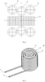
- the condensation member 30 includes a plurality of third condensation pipe segments 33 successively arranged from outside to inside, two adjacent third condensation pipe segments 33 are communicated with each other, and each of the third condensation pipe segments 33 is formed by a third condensation pipe helically encircling the center axis of the air duct 10.
- a helical line of each of the third condensation pipe segments 33 is substantially located in a same cylindrical surface.
- a difference value between diameters of the cylindrical surfaces where the helical lines of two adjacent third condensation pipe segments 33 are located is a constant value.
- the helical line of each of the third condensation pipe segments 33 can also be located in a same conical surface, the helical line of each of the third condensation pipe segments 33 gradually extends inwards from up to down, the inner diameter of the air duct 10 is gradually reduced from up to down, and a gap is provided between the air duct 10 and an outermost third condensation pipe segment 33.
- the shape of the air duct 10 can provide guide for the ambient air to enter in or flow out, allowing the ambient air to enter in or flow out of the air channel 11 more quickly and smoothly, improving the heat exchange effect.
- an inlet and an outlet of each of the third condensation pipe segments 33 is defined at an uppermost end and at a lowermost end respectively.
- an inlet of one third condensation pipe segment 33 is aligned and communicated with an outlet of the other third condensation pipe segment 33.
- the refrigerant flows from up to down (or from down to up) in each of the third condensation pipe segments 33, and is transmitted between two adjacent third condensation pipe segments 33 from inside to outside (or from outside to inside), improving the heat exchange effect of the condenser 100.
- the refrigerant inlet a and the refrigerant outlet b extend out of the air duct 10 through a through hole 13 located at the bottom of the air duct 10.
- the refrigerant inlet a is communicated with a compressor outlet of the refrigerator, and the refrigerant outlet b is communicated with an inlet of a throttling device, thus achieving the condensation of the gas refrigerant at high temperature and high pressure in the refrigeration system.
- an up-and-down direction is consistent with the axial direction of the air duct 10.
- An end, adjacent to the air supply device 20, of the air channel 11 (or the air duct 10) is defined as a lower end, and an end, far away from the air supply device 20, of the air channel 11 (or the air duct 10) is defined as an upper end.
- the airflow can be guided in from the upper end of the air duct 10 and guided out from the lower end of the air duct 10 by the air supply device 20, and can also be guided in from the lower end of the air duct 10 and guided out from the upper end of the air duct 10 by the air supply device 20.
- Pipe diameter, pipe wall thickness, pipe length and pipe materials of the first to third condensation pipes each influence cooling effect and service life of the condenser 100, and can be designed according to types and specifications of the refrigerators.
- the pipe materials of the first to third condensation pipes can be metal (such as a copper pipe, an aluminum pipe, an iron pipe or the like), which provides good heat conductivity and pressure resistance.
- Inner and outer surfaces of the respective condensation pipes can be processed by electroplating and corrosion prevention.
- the metal which is processed by surface anti-rust treatment can be adopted for the air duct 10 (such as a galvanized steel sheet or a stainless steel sheet), and the air duct 10 can also be a plastic molded piece which is heatproof and flame-retardant.
- the bottom of the air duct 10 has a mounting bottom foot 12 for being connected with the fan, the mounting bottom foot 12 has a mounting hole 121, and the air supply device 20 is fixedly connected with the bottom foot 12 through a bolt.
- the air supply device 20 can use a mini direct-current fan.
- the direct-current fan can be an induced draft fan or a suction fan, and the power and specification of the direct-current fan can be matched according to the types and specifications of the refrigerators and the dimension of the condensation pipes.
- the air supply device 20 is fixed to the refrigeration device through a mounting support 40.
- a refrigerator according to embodiments of a second aspect of the present disclosure includes the condenser 100 of the above-mentioned embodiments.
- the refrigerator using the above-mentioned condenser 100 has a better refrigeration effect.
- the refrigerant absorbs the heat inside the refrigerator body in an evaporator of the refrigerator, becomes steam at high temperature and high pressure under the compression of the compressor, and the steam is sent to the condenser 100.
- the condenser 100 dissipates heat to the ambient air and condenses the steam at high temperature and high pressure into liquid refrigerant, which is throttled through the throttling device and is sent into the evaporator.
- the refrigerant in the evaporator boils and evaporates violently due to the reduced pressure, and absorbs the heat of the cooled object in the refrigerator body, thereby generating the refrigeration effect.
- the refrigerant steam is sent to the compressor again, and the circulation repeats in such way.
- the refrigerator has a compressor room for at least containing the compressor, and the air supply device 20 is fixed in the compressor room through the mounting support 40.
- the space in the compressor room is reasonably used, and when the complete machine operates, the highly effective heat exchange between the refrigerant and the ambient environment is achieved, thereby improving the refrigeration efficiency.
- first and second are used herein for purposes of description and are not intended to indicate or imply relative importance or significance or to imply the number of indicated technical features.
- the feature defined with “first” and “second” may comprise one or more of this feature.
- a plurality of' means two or more than two, unless specified otherwise.
- the terms “mounted,” “connected,” “coupled,” “fixed” and the like are used broadly, and may be, for example, fixed connections, detachable connections, or integral connections; may also be mechanical or electrical connections; may also be direct connections or indirect connections via intervening structures; may also be inner communications of two elements, which can be understood by those skilled in the art according to specific situations.
- a structure in which a first feature is "on" or “below” a second feature may include an embodiment in which the first feature is in direct contact with the second feature, and may also include an embodiment in which the first feature and the second feature are not in direct contact with each other, but are contacted via an additional feature formed therebetween.
- a first feature "on,” “above,” or “on top of' a second feature may include an embodiment in which the first feature is right or obliquely “on,” “above,” or “on top of' the second feature, or just means that the first feature is at a height higher than that of the second feature; while a first feature "below,” “under,” or “on bottom of' a second feature may include an embodiment in which the first feature is right or obliquely “below,” “under,” or “on bottom of' the second feature, or just means that the first feature is at a height lower than that of the second feature.
Landscapes
- Engineering & Computer Science (AREA)
- Mechanical Engineering (AREA)
- General Engineering & Computer Science (AREA)
- Physics & Mathematics (AREA)
- Thermal Sciences (AREA)
- Chemical & Material Sciences (AREA)
- Combustion & Propulsion (AREA)
- Heat-Exchange Devices With Radiators And Conduit Assemblies (AREA)
Claims (8)
- Kondensator (100), umfassend:eine Luftleitung (10), die einen Luftkanal (11) darin definiert;eine Luftzufuhrvorrichtung (20), die fest mit der Luftleitung (10) verbunden ist; undein Kondensationselement (30) aufweisend einen Kältemitteleinlass (a) und einen Kältemittelauslass (b), wobei das Kondensationselement (30) zumindest teilweise in dem Luftkanal (11) angeordnet ist,dadurch gekennzeichnet, dassdas Kondensationselement (30) Folgendes umfasst:eine Vielzahl von ersten Kondensationsrohrsegmenten (31), die nacheinander in einer axialen Richtung der Luftleitung (10) angeordnet sind und miteinander verbunden sind, wobei jedes der ersten Kondensationsrohrsegmente (32) spiralförmig durch ein erstes Kondensationsrohr gebildet ist, und sich eine Spirallinie jedes der ersten Kondensationsrohrsegmente (31) in einer gleichen Ringfläche befindet; undein zweites Kondensationsrohrsegment (32), das mit mindestens einem der Vielzahl von ersten Kondensationsrohrsegmenten (31) verbunden ist, wobei das zweite Kondensationsrohrsegment (32) an einer Innenseite der Vielzahl von ersten Kondensationsrohrsegmenten (31) angeordnet ist;wobei das zweite Kondensationsrohrsegment (32) durch ein zweites Kondensationsrohr gebildet ist, das eine Mittelachse der Luftleitung (10) spiralförmig umgibt.
- Kondensator (100) gemäß Anspruch 1, wobei jedes der ersten Kondensationsrohrsegmente (31) eine Innenseite aufweist, die sich in einem gleichen inneren Kreisring (311) befindet, und eine Außenseite, die sich in einem gleichen äußeren Kreisring (312) befindet, wobei die inneren Kreisringe (311) der Vielzahl von ersten Kondensationsrohrsegmenten (31) koaxial angeordnet sind und die äußeren Kreisringe (312) der Vielzahl von ersten Kondensationsrohrsegmenten (31) koaxial angeordnet sind, wobei ein Innendurchmesser der Luftleitung (10) bevorzugt größer als ein Durchmesser des äußeren Kreisrings (312) ist.
- Kondensator (100) gemäß Anspruch 2, wobei umlaufende Zentren (313) von zwei benachbarten ersten Kondensationsrohrsegmenten (31) koaxial vorgesehen sind und die umlaufenden Zentren (313) der zwei benachbarten ersten Kondensationsrohrsegmente (31) unterschiedliche Durchmesser aufweisen; wenn die Anzahl der ersten Kondensationsrohrsegmente (31) gleich oder größer als zwei ist, weisen das umlaufende Zentrum (313) jedes ersten Kondensationsrohrsegments (31) und das umlaufende Zentrum (313) des darunter benachbarten ersten Kondensationsrohrsegments (31) den gleichen Durchmesser auf.
- Kondensator (100) gemäß Anspruch 1, wobei das zweite Kondensationsrohrsegment (32) und die Vielzahl von ersten Kondensationsrohrsegmenten (31) nacheinander verbunden sind, der Kältemitteleinlass (a) in dem zweiten Kondensationsrohrsegment (32) definiert ist und der Kältemittelauslass (b) in einem der Vielzahl von ersten Kondensationsrohrsegmenten (31) definiert ist, oder der Kältemittelauslass (b) in dem zweiten Kondensationsrohrsegment (32) definiert und der Kältemitteleinlass (a) in einem der Vielzahl von ersten Kondensationsrohrsegmenten (31) definiert ist.
- Kondensator (100) gemäß Anspruch 4, wobei ein oberes Ende des zweiten Kondensationsrohrsegments (32) mit dem obersten ersten Kondensationsrohrsegment (31) verbunden ist, das darüber liegende erste Kondensationsrohrsegment (31) mit dem darunter liegenden benachbarten ersten Kondensationsrohrsegment (31) verbunden ist, der Kältemitteleinlass (a) in einem des zweiten Kondensationsrohrsegments (32) und des untersten ersten Kondensationsrohrsegments (31) definiert ist, und der Kältemittelauslass (b) in dem anderen des zweiten Kondensationsrohrsegments (32) und des untersten ersten Kondensationsrohrsegments (31) definiert ist.
- Kondensator (100) gemäß einem der Ansprüche 1 bis 5, wobei sich der Kältemitteleinlass (a) und der Kältemittelauslass (b) aus der Luftleitung (10) durch ein Durchgangsloch (13) erstrecken, das sich an einem Boden der Luftleitung (10) befindet.
- Kühlschrank, umfassend einen Kondensator (100) gemäß einem der Ansprüche 1-6.
- Kühlschrank gemäß Anspruch 7, wobei der Kühlschrank einen Kompressorraum aufweist, um zumindest einen Kompressor aufzunehmen, und eine Luftzufuhrvorrichtung (20) in dem Kompressorraum durch eine Montagehalterung (40) befestigt ist.
Priority Applications (1)
| Application Number | Priority Date | Filing Date | Title |
|---|---|---|---|
| PL16899083T PL3339772T3 (pl) | 2016-04-21 | 2016-05-31 | Skraplacz i mająca go lodówka |
Applications Claiming Priority (2)
| Application Number | Priority Date | Filing Date | Title |
|---|---|---|---|
| CN201610260026.9A CN105953481A (zh) | 2016-04-21 | 2016-04-21 | 冷凝器以及具有它的冰箱 |
| PCT/CN2016/084157 WO2017181496A1 (zh) | 2016-04-21 | 2016-05-31 | 冷凝器以及具有它的冰箱 |
Publications (3)
| Publication Number | Publication Date |
|---|---|
| EP3339772A1 EP3339772A1 (de) | 2018-06-27 |
| EP3339772A4 EP3339772A4 (de) | 2019-02-20 |
| EP3339772B1 true EP3339772B1 (de) | 2022-01-19 |
Family
ID=56915177
Family Applications (1)
| Application Number | Title | Priority Date | Filing Date |
|---|---|---|---|
| EP16899083.6A Active EP3339772B1 (de) | 2016-04-21 | 2016-05-31 | Kondensator und kühlschrank damit |
Country Status (5)
| Country | Link |
|---|---|
| US (1) | US10808986B2 (de) |
| EP (1) | EP3339772B1 (de) |
| CN (1) | CN105953481A (de) |
| PL (1) | PL3339772T3 (de) |
| WO (1) | WO2017181496A1 (de) |
Families Citing this family (2)
| Publication number | Priority date | Publication date | Assignee | Title |
|---|---|---|---|---|
| CN110425595A (zh) * | 2019-07-31 | 2019-11-08 | 安徽冠东科技有限公司 | 一种环形螺旋式余热利用装置 |
| CN111442574A (zh) * | 2020-05-06 | 2020-07-24 | 长虹美菱股份有限公司 | 一种冰箱内置复合冷凝器 |
Family Cites Families (17)
| Publication number | Priority date | Publication date | Assignee | Title |
|---|---|---|---|---|
| JPH07270035A (ja) * | 1994-03-29 | 1995-10-20 | Toshiba Corp | 冷蔵庫 |
| CN1302248C (zh) * | 2002-10-10 | 2007-02-28 | 维尼亚万都株式会社 | 螺旋式热交换装置 |
| ITTO20040022A1 (it) * | 2004-01-22 | 2004-04-22 | Cosmogas Srl | Scambiatore di calore, in particolare del tipo a condensazione |
| KR100713819B1 (ko) * | 2005-12-12 | 2007-05-07 | 위니아만도 주식회사 | 김치저장고용 나선형 응축기 |
| KR20080101356A (ko) * | 2007-05-17 | 2008-11-21 | 엘지전자 주식회사 | 냉장고 |
| CN202158706U (zh) * | 2010-04-26 | 2012-03-07 | 株式会社东芝 | 冰箱 |
| CN101995117B (zh) * | 2010-10-12 | 2012-07-04 | 宣伯民 | 房间空气调节器管流式冷凝器 |
| CN201858909U (zh) * | 2010-10-30 | 2011-06-08 | 大庆石油管理局 | 塔式高效升华物质冷凝收集器 |
| US20120060545A1 (en) * | 2010-12-02 | 2012-03-15 | General Electric Company | Condenser assembly for multiple refrigeration systems |
| JP2012255638A (ja) * | 2011-06-10 | 2012-12-27 | Toshiba Corp | 冷蔵庫 |
| CN202133219U (zh) * | 2011-06-22 | 2012-02-01 | 宁波罗特电器有限公司 | 冷藏柜的冷凝器结构 |
| CN102937388B (zh) * | 2011-08-15 | 2014-11-19 | 杨永利 | 用于钻井平台的余热回收换热器 |
| CN102494469B (zh) * | 2011-12-06 | 2014-02-26 | 合肥美的电冰箱有限公司 | 用于冰柜的制冷系统和具有该制冷系统的冰柜 |
| CN202885359U (zh) * | 2012-10-24 | 2013-04-17 | 合肥美菱股份有限公司 | 一种冷凝器 |
| CN102927745A (zh) * | 2012-10-24 | 2013-02-13 | 合肥美菱股份有限公司 | 一种冰箱强制散热结构 |
| CN103822410A (zh) * | 2014-02-21 | 2014-05-28 | 合肥美的电冰箱有限公司 | 用于冰箱的冷凝器组件和具有该冷凝器组件的冰箱 |
| CN204027382U (zh) * | 2014-06-26 | 2014-12-17 | 骆继洪 | 一种废热水热能回收装置 |
-
2016
- 2016-04-21 CN CN201610260026.9A patent/CN105953481A/zh active Pending
- 2016-05-31 EP EP16899083.6A patent/EP3339772B1/de active Active
- 2016-05-31 PL PL16899083T patent/PL3339772T3/pl unknown
- 2016-05-31 WO PCT/CN2016/084157 patent/WO2017181496A1/zh not_active Ceased
-
2018
- 2018-07-02 US US16/025,723 patent/US10808986B2/en active Active
Non-Patent Citations (1)
| Title |
|---|
| None * |
Also Published As
| Publication number | Publication date |
|---|---|
| EP3339772A4 (de) | 2019-02-20 |
| US20180320951A1 (en) | 2018-11-08 |
| PL3339772T3 (pl) | 2022-05-23 |
| CN105953481A (zh) | 2016-09-21 |
| WO2017181496A1 (zh) | 2017-10-26 |
| US10808986B2 (en) | 2020-10-20 |
| EP3339772A1 (de) | 2018-06-27 |
Similar Documents
| Publication | Publication Date | Title |
|---|---|---|
| EP2762821B1 (de) | Klimaanlage und Wärmetauscher dafür | |
| US20070214823A1 (en) | Heat exchanging device for refrigerator | |
| EP3339772B1 (de) | Kondensator und kühlschrank damit | |
| EP3156744B1 (de) | Kondensator und kühlschrank damit | |
| US10436219B2 (en) | Fins, tubes, and structures for fin array for use in a centrifugal fan | |
| KR102402382B1 (ko) | 냉동컴프레셔용 공냉식 가스냉각기 | |
| US9243650B2 (en) | Fin array for use in a centrifugal fan | |
| CN107461798B (zh) | 空调余热集热供水装置 | |
| CN222012365U (zh) | 一种自动水循环干湿联合蒸发器 | |
| CN111735192A (zh) | 壳体组件和具有其的空调器 | |
| CN221781027U (zh) | 一种盘管式冷水机 | |
| CN210345940U (zh) | 一种风冷式冷水机 | |
| KR101679575B1 (ko) | 열교환기 | |
| KR100771453B1 (ko) | 턴핀 열교환기 | |
| KR102104609B1 (ko) | 팬커버 | |
| KR101582580B1 (ko) | 열교환기 | |
| CN108106462A (zh) | 热泵空调扰流单系统蒸发器 | |
| CN108954934A (zh) | 中央空调扰流单系统干式蒸发器 | |
| CN108106090A (zh) | 热泵空调扰流蒸发器 | |
| CN108954965A (zh) | 冷水机组扰流双系统蒸发器 | |
| CN108954930A (zh) | 中央空调扰流双系统干式蒸发器 | |
| CN108120326A (zh) | 热泵空调扰流双系统干式蒸发器 | |
| CN108954964A (zh) | 热泵机组单系统干式蒸发器 | |
| CN108120059A (zh) | 热泵机组扰流蒸发器 | |
| CN109000291A (zh) | 油烟机 |
Legal Events
| Date | Code | Title | Description |
|---|---|---|---|
| STAA | Information on the status of an ep patent application or granted ep patent |
Free format text: STATUS: THE INTERNATIONAL PUBLICATION HAS BEEN MADE |
|
| PUAI | Public reference made under article 153(3) epc to a published international application that has entered the european phase |
Free format text: ORIGINAL CODE: 0009012 |
|
| STAA | Information on the status of an ep patent application or granted ep patent |
Free format text: STATUS: REQUEST FOR EXAMINATION WAS MADE |
|
| 17P | Request for examination filed |
Effective date: 20180319 |
|
| AK | Designated contracting states |
Kind code of ref document: A1 Designated state(s): AL AT BE BG CH CY CZ DE DK EE ES FI FR GB GR HR HU IE IS IT LI LT LU LV MC MK MT NL NO PL PT RO RS SE SI SK SM TR |
|
| AX | Request for extension of the european patent |
Extension state: BA ME |
|
| A4 | Supplementary search report drawn up and despatched |
Effective date: 20190122 |
|
| RIC1 | Information provided on ipc code assigned before grant |
Ipc: F25D 19/00 20060101AFI20190117BHEP Ipc: F25B 39/04 20060101ALI20190117BHEP Ipc: F28D 7/02 20060101ALI20190117BHEP |
|
| DAV | Request for validation of the european patent (deleted) | ||
| DAX | Request for extension of the european patent (deleted) | ||
| STAA | Information on the status of an ep patent application or granted ep patent |
Free format text: STATUS: EXAMINATION IS IN PROGRESS |
|
| 17Q | First examination report despatched |
Effective date: 20200602 |
|
| GRAP | Despatch of communication of intention to grant a patent |
Free format text: ORIGINAL CODE: EPIDOSNIGR1 |
|
| STAA | Information on the status of an ep patent application or granted ep patent |
Free format text: STATUS: GRANT OF PATENT IS INTENDED |
|
| GRAJ | Information related to disapproval of communication of intention to grant by the applicant or resumption of examination proceedings by the epo deleted |
Free format text: ORIGINAL CODE: EPIDOSDIGR1 |
|
| STAA | Information on the status of an ep patent application or granted ep patent |
Free format text: STATUS: EXAMINATION IS IN PROGRESS |
|
| INTG | Intention to grant announced |
Effective date: 20210928 |
|
| GRAS | Grant fee paid |
Free format text: ORIGINAL CODE: EPIDOSNIGR3 |
|
| INTC | Intention to grant announced (deleted) | ||
| STAA | Information on the status of an ep patent application or granted ep patent |
Free format text: STATUS: GRANT OF PATENT IS INTENDED |
|
| GRAP | Despatch of communication of intention to grant a patent |
Free format text: ORIGINAL CODE: EPIDOSNIGR1 |
|
| GRAA | (expected) grant |
Free format text: ORIGINAL CODE: 0009210 |
|
| STAA | Information on the status of an ep patent application or granted ep patent |
Free format text: STATUS: THE PATENT HAS BEEN GRANTED |
|
| INTG | Intention to grant announced |
Effective date: 20211208 |
|
| AK | Designated contracting states |
Kind code of ref document: B1 Designated state(s): AL AT BE BG CH CY CZ DE DK EE ES FI FR GB GR HR HU IE IS IT LI LT LU LV MC MK MT NL NO PL PT RO RS SE SI SK SM TR |
|
| REG | Reference to a national code |
Ref country code: GB Ref legal event code: FG4D |
|
| REG | Reference to a national code |
Ref country code: CH Ref legal event code: EP |
|
| REG | Reference to a national code |
Ref country code: DE Ref legal event code: R096 Ref document number: 602016068556 Country of ref document: DE |
|
| REG | Reference to a national code |
Ref country code: AT Ref legal event code: REF Ref document number: 1464031 Country of ref document: AT Kind code of ref document: T Effective date: 20220215 |
|
| REG | Reference to a national code |
Ref country code: IE Ref legal event code: FG4D |
|
| REG | Reference to a national code |
Ref country code: LT Ref legal event code: MG9D |
|
| REG | Reference to a national code |
Ref country code: NL Ref legal event code: MP Effective date: 20220119 |
|
| REG | Reference to a national code |
Ref country code: AT Ref legal event code: MK05 Ref document number: 1464031 Country of ref document: AT Kind code of ref document: T Effective date: 20220119 |
|
| PG25 | Lapsed in a contracting state [announced via postgrant information from national office to epo] |
Ref country code: NL Free format text: LAPSE BECAUSE OF FAILURE TO SUBMIT A TRANSLATION OF THE DESCRIPTION OR TO PAY THE FEE WITHIN THE PRESCRIBED TIME-LIMIT Effective date: 20220119 |
|
| PG25 | Lapsed in a contracting state [announced via postgrant information from national office to epo] |
Ref country code: SE Free format text: LAPSE BECAUSE OF FAILURE TO SUBMIT A TRANSLATION OF THE DESCRIPTION OR TO PAY THE FEE WITHIN THE PRESCRIBED TIME-LIMIT Effective date: 20220119 Ref country code: RS Free format text: LAPSE BECAUSE OF FAILURE TO SUBMIT A TRANSLATION OF THE DESCRIPTION OR TO PAY THE FEE WITHIN THE PRESCRIBED TIME-LIMIT Effective date: 20220119 Ref country code: PT Free format text: LAPSE BECAUSE OF FAILURE TO SUBMIT A TRANSLATION OF THE DESCRIPTION OR TO PAY THE FEE WITHIN THE PRESCRIBED TIME-LIMIT Effective date: 20220519 Ref country code: NO Free format text: LAPSE BECAUSE OF FAILURE TO SUBMIT A TRANSLATION OF THE DESCRIPTION OR TO PAY THE FEE WITHIN THE PRESCRIBED TIME-LIMIT Effective date: 20220419 Ref country code: LT Free format text: LAPSE BECAUSE OF FAILURE TO SUBMIT A TRANSLATION OF THE DESCRIPTION OR TO PAY THE FEE WITHIN THE PRESCRIBED TIME-LIMIT Effective date: 20220119 Ref country code: HR Free format text: LAPSE BECAUSE OF FAILURE TO SUBMIT A TRANSLATION OF THE DESCRIPTION OR TO PAY THE FEE WITHIN THE PRESCRIBED TIME-LIMIT Effective date: 20220119 Ref country code: ES Free format text: LAPSE BECAUSE OF FAILURE TO SUBMIT A TRANSLATION OF THE DESCRIPTION OR TO PAY THE FEE WITHIN THE PRESCRIBED TIME-LIMIT Effective date: 20220119 Ref country code: BG Free format text: LAPSE BECAUSE OF FAILURE TO SUBMIT A TRANSLATION OF THE DESCRIPTION OR TO PAY THE FEE WITHIN THE PRESCRIBED TIME-LIMIT Effective date: 20220419 |
|
| PG25 | Lapsed in a contracting state [announced via postgrant information from national office to epo] |
Ref country code: LV Free format text: LAPSE BECAUSE OF FAILURE TO SUBMIT A TRANSLATION OF THE DESCRIPTION OR TO PAY THE FEE WITHIN THE PRESCRIBED TIME-LIMIT Effective date: 20220119 Ref country code: FI Free format text: LAPSE BECAUSE OF FAILURE TO SUBMIT A TRANSLATION OF THE DESCRIPTION OR TO PAY THE FEE WITHIN THE PRESCRIBED TIME-LIMIT Effective date: 20220119 Ref country code: AT Free format text: LAPSE BECAUSE OF FAILURE TO SUBMIT A TRANSLATION OF THE DESCRIPTION OR TO PAY THE FEE WITHIN THE PRESCRIBED TIME-LIMIT Effective date: 20220119 |
|
| PG25 | Lapsed in a contracting state [announced via postgrant information from national office to epo] |
Ref country code: IS Free format text: LAPSE BECAUSE OF FAILURE TO SUBMIT A TRANSLATION OF THE DESCRIPTION OR TO PAY THE FEE WITHIN THE PRESCRIBED TIME-LIMIT Effective date: 20220519 |
|
| REG | Reference to a national code |
Ref country code: DE Ref legal event code: R097 Ref document number: 602016068556 Country of ref document: DE |
|
| PG25 | Lapsed in a contracting state [announced via postgrant information from national office to epo] |
Ref country code: SM Free format text: LAPSE BECAUSE OF FAILURE TO SUBMIT A TRANSLATION OF THE DESCRIPTION OR TO PAY THE FEE WITHIN THE PRESCRIBED TIME-LIMIT Effective date: 20220119 Ref country code: SK Free format text: LAPSE BECAUSE OF FAILURE TO SUBMIT A TRANSLATION OF THE DESCRIPTION OR TO PAY THE FEE WITHIN THE PRESCRIBED TIME-LIMIT Effective date: 20220119 Ref country code: RO Free format text: LAPSE BECAUSE OF FAILURE TO SUBMIT A TRANSLATION OF THE DESCRIPTION OR TO PAY THE FEE WITHIN THE PRESCRIBED TIME-LIMIT Effective date: 20220119 Ref country code: EE Free format text: LAPSE BECAUSE OF FAILURE TO SUBMIT A TRANSLATION OF THE DESCRIPTION OR TO PAY THE FEE WITHIN THE PRESCRIBED TIME-LIMIT Effective date: 20220119 Ref country code: DK Free format text: LAPSE BECAUSE OF FAILURE TO SUBMIT A TRANSLATION OF THE DESCRIPTION OR TO PAY THE FEE WITHIN THE PRESCRIBED TIME-LIMIT Effective date: 20220119 Ref country code: CZ Free format text: LAPSE BECAUSE OF FAILURE TO SUBMIT A TRANSLATION OF THE DESCRIPTION OR TO PAY THE FEE WITHIN THE PRESCRIBED TIME-LIMIT Effective date: 20220119 |
|
| PLBE | No opposition filed within time limit |
Free format text: ORIGINAL CODE: 0009261 |
|
| STAA | Information on the status of an ep patent application or granted ep patent |
Free format text: STATUS: NO OPPOSITION FILED WITHIN TIME LIMIT |
|
| PG25 | Lapsed in a contracting state [announced via postgrant information from national office to epo] |
Ref country code: AL Free format text: LAPSE BECAUSE OF FAILURE TO SUBMIT A TRANSLATION OF THE DESCRIPTION OR TO PAY THE FEE WITHIN THE PRESCRIBED TIME-LIMIT Effective date: 20220119 |
|
| 26N | No opposition filed |
Effective date: 20221020 |
|
| REG | Reference to a national code |
Ref country code: CH Ref legal event code: PL |
|
| REG | Reference to a national code |
Ref country code: BE Ref legal event code: MM Effective date: 20220531 |
|
| PG25 | Lapsed in a contracting state [announced via postgrant information from national office to epo] |
Ref country code: MC Free format text: LAPSE BECAUSE OF FAILURE TO SUBMIT A TRANSLATION OF THE DESCRIPTION OR TO PAY THE FEE WITHIN THE PRESCRIBED TIME-LIMIT Effective date: 20220119 Ref country code: LU Free format text: LAPSE BECAUSE OF NON-PAYMENT OF DUE FEES Effective date: 20220531 Ref country code: LI Free format text: LAPSE BECAUSE OF NON-PAYMENT OF DUE FEES Effective date: 20220531 Ref country code: CH Free format text: LAPSE BECAUSE OF NON-PAYMENT OF DUE FEES Effective date: 20220531 |
|
| PG25 | Lapsed in a contracting state [announced via postgrant information from national office to epo] |
Ref country code: SI Free format text: LAPSE BECAUSE OF FAILURE TO SUBMIT A TRANSLATION OF THE DESCRIPTION OR TO PAY THE FEE WITHIN THE PRESCRIBED TIME-LIMIT Effective date: 20220119 |
|
| PG25 | Lapsed in a contracting state [announced via postgrant information from national office to epo] |
Ref country code: IE Free format text: LAPSE BECAUSE OF NON-PAYMENT OF DUE FEES Effective date: 20220531 |
|
| PG25 | Lapsed in a contracting state [announced via postgrant information from national office to epo] |
Ref country code: BE Free format text: LAPSE BECAUSE OF NON-PAYMENT OF DUE FEES Effective date: 20220531 |
|
| PG25 | Lapsed in a contracting state [announced via postgrant information from national office to epo] |
Ref country code: HU Free format text: LAPSE BECAUSE OF FAILURE TO SUBMIT A TRANSLATION OF THE DESCRIPTION OR TO PAY THE FEE WITHIN THE PRESCRIBED TIME-LIMIT; INVALID AB INITIO Effective date: 20160531 |
|
| PG25 | Lapsed in a contracting state [announced via postgrant information from national office to epo] |
Ref country code: MK Free format text: LAPSE BECAUSE OF FAILURE TO SUBMIT A TRANSLATION OF THE DESCRIPTION OR TO PAY THE FEE WITHIN THE PRESCRIBED TIME-LIMIT Effective date: 20220119 Ref country code: CY Free format text: LAPSE BECAUSE OF FAILURE TO SUBMIT A TRANSLATION OF THE DESCRIPTION OR TO PAY THE FEE WITHIN THE PRESCRIBED TIME-LIMIT Effective date: 20220119 |
|
| PG25 | Lapsed in a contracting state [announced via postgrant information from national office to epo] |
Ref country code: MT Free format text: LAPSE BECAUSE OF FAILURE TO SUBMIT A TRANSLATION OF THE DESCRIPTION OR TO PAY THE FEE WITHIN THE PRESCRIBED TIME-LIMIT Effective date: 20220119 |
|
| PG25 | Lapsed in a contracting state [announced via postgrant information from national office to epo] |
Ref country code: GR Free format text: LAPSE BECAUSE OF NON-PAYMENT OF DUE FEES Effective date: 20220119 |
|
| PG25 | Lapsed in a contracting state [announced via postgrant information from national office to epo] |
Ref country code: GR Free format text: LAPSE BECAUSE OF NON-PAYMENT OF DUE FEES Effective date: 20220119 |
|
| PGFP | Annual fee paid to national office [announced via postgrant information from national office to epo] |
Ref country code: PL Payment date: 20250422 Year of fee payment: 10 Ref country code: DE Payment date: 20250516 Year of fee payment: 10 |
|
| PGFP | Annual fee paid to national office [announced via postgrant information from national office to epo] |
Ref country code: GB Payment date: 20250519 Year of fee payment: 10 |
|
| PGFP | Annual fee paid to national office [announced via postgrant information from national office to epo] |
Ref country code: IT Payment date: 20250519 Year of fee payment: 10 |
|
| PGFP | Annual fee paid to national office [announced via postgrant information from national office to epo] |
Ref country code: FR Payment date: 20250519 Year of fee payment: 10 |
|
| PGFP | Annual fee paid to national office [announced via postgrant information from national office to epo] |
Ref country code: TR Payment date: 20250424 Year of fee payment: 10 |