EP3339738B1 - Turbine including fuel gas recirculation combustor - Google Patents
Turbine including fuel gas recirculation combustor Download PDFInfo
- Publication number
- EP3339738B1 EP3339738B1 EP17202951.4A EP17202951A EP3339738B1 EP 3339738 B1 EP3339738 B1 EP 3339738B1 EP 17202951 A EP17202951 A EP 17202951A EP 3339738 B1 EP3339738 B1 EP 3339738B1
- Authority
- EP
- European Patent Office
- Prior art keywords
- nozzle
- combustor
- nozzle casing
- flue gas
- gas recirculation
- Prior art date
- Legal status (The legal status is an assumption and is not a legal conclusion. Google has not performed a legal analysis and makes no representation as to the accuracy of the status listed.)
- Active
Links
- 239000002737 fuel gas Substances 0.000 title claims description 3
- 238000002485 combustion reaction Methods 0.000 claims description 44
- 239000000446 fuel Substances 0.000 claims description 29
- 239000007789 gas Substances 0.000 claims description 24
- 238000002347 injection Methods 0.000 claims description 19
- 239000007924 injection Substances 0.000 claims description 19
- UGFAIRIUMAVXCW-UHFFFAOYSA-N Carbon monoxide Chemical compound [O+]#[C-] UGFAIRIUMAVXCW-UHFFFAOYSA-N 0.000 claims description 17
- 239000003546 flue gas Substances 0.000 claims description 17
- 238000005192 partition Methods 0.000 claims description 9
- 239000000567 combustion gas Substances 0.000 claims description 5
- 230000037361 pathway Effects 0.000 claims 5
- MWUXSHHQAYIFBG-UHFFFAOYSA-N nitrogen oxide Inorganic materials O=[N] MWUXSHHQAYIFBG-UHFFFAOYSA-N 0.000 description 57
- 239000000203 mixture Substances 0.000 description 12
- QVGXLLKOCUKJST-UHFFFAOYSA-N atomic oxygen Chemical compound [O] QVGXLLKOCUKJST-UHFFFAOYSA-N 0.000 description 8
- 239000001301 oxygen Substances 0.000 description 8
- 229910052760 oxygen Inorganic materials 0.000 description 8
- 239000003595 mist Substances 0.000 description 4
- 230000000694 effects Effects 0.000 description 3
- CURLTUGMZLYLDI-UHFFFAOYSA-N Carbon dioxide Chemical compound O=C=O CURLTUGMZLYLDI-UHFFFAOYSA-N 0.000 description 2
- 230000003134 recirculating effect Effects 0.000 description 2
- 239000003570 air Substances 0.000 description 1
- 238000007664 blowing Methods 0.000 description 1
- 229910002092 carbon dioxide Inorganic materials 0.000 description 1
- 239000001569 carbon dioxide Substances 0.000 description 1
- 239000003344 environmental pollutant Substances 0.000 description 1
- 238000003912 environmental pollution Methods 0.000 description 1
- 230000006872 improvement Effects 0.000 description 1
- 230000000977 initiatory effect Effects 0.000 description 1
- 238000009434 installation Methods 0.000 description 1
- 239000007788 liquid Substances 0.000 description 1
- 238000000034 method Methods 0.000 description 1
- 238000012986 modification Methods 0.000 description 1
- 230000004048 modification Effects 0.000 description 1
- 231100000719 pollutant Toxicity 0.000 description 1
- 230000036316 preload Effects 0.000 description 1
- 230000004044 response Effects 0.000 description 1
- 230000035945 sensitivity Effects 0.000 description 1
- 239000000243 solution Substances 0.000 description 1
- 230000008016 vaporization Effects 0.000 description 1
Images


Classifications
-
- F—MECHANICAL ENGINEERING; LIGHTING; HEATING; WEAPONS; BLASTING
- F02—COMBUSTION ENGINES; HOT-GAS OR COMBUSTION-PRODUCT ENGINE PLANTS
- F02C—GAS-TURBINE PLANTS; AIR INTAKES FOR JET-PROPULSION PLANTS; CONTROLLING FUEL SUPPLY IN AIR-BREATHING JET-PROPULSION PLANTS
- F02C3/00—Gas-turbine plants characterised by the use of combustion products as the working fluid
- F02C3/34—Gas-turbine plants characterised by the use of combustion products as the working fluid with recycling of part of the working fluid, i.e. semi-closed cycles with combustion products in the closed part of the cycle
-
- F—MECHANICAL ENGINEERING; LIGHTING; HEATING; WEAPONS; BLASTING
- F23—COMBUSTION APPARATUS; COMBUSTION PROCESSES
- F23R—GENERATING COMBUSTION PRODUCTS OF HIGH PRESSURE OR HIGH VELOCITY, e.g. GAS-TURBINE COMBUSTION CHAMBERS
- F23R3/00—Continuous combustion chambers using liquid or gaseous fuel
- F23R3/28—Continuous combustion chambers using liquid or gaseous fuel characterised by the fuel supply
- F23R3/286—Continuous combustion chambers using liquid or gaseous fuel characterised by the fuel supply having fuel-air premixing devices
-
- F—MECHANICAL ENGINEERING; LIGHTING; HEATING; WEAPONS; BLASTING
- F02—COMBUSTION ENGINES; HOT-GAS OR COMBUSTION-PRODUCT ENGINE PLANTS
- F02C—GAS-TURBINE PLANTS; AIR INTAKES FOR JET-PROPULSION PLANTS; CONTROLLING FUEL SUPPLY IN AIR-BREATHING JET-PROPULSION PLANTS
- F02C7/00—Features, components parts, details or accessories, not provided for in, or of interest apart form groups F02C1/00 - F02C6/00; Air intakes for jet-propulsion plants
- F02C7/22—Fuel supply systems
-
- F—MECHANICAL ENGINEERING; LIGHTING; HEATING; WEAPONS; BLASTING
- F02—COMBUSTION ENGINES; HOT-GAS OR COMBUSTION-PRODUCT ENGINE PLANTS
- F02C—GAS-TURBINE PLANTS; AIR INTAKES FOR JET-PROPULSION PLANTS; CONTROLLING FUEL SUPPLY IN AIR-BREATHING JET-PROPULSION PLANTS
- F02C9/00—Controlling gas-turbine plants; Controlling fuel supply in air- breathing jet-propulsion plants
- F02C9/26—Control of fuel supply
- F02C9/40—Control of fuel supply specially adapted to the use of a special fuel or a plurality of fuels
-
- F—MECHANICAL ENGINEERING; LIGHTING; HEATING; WEAPONS; BLASTING
- F23—COMBUSTION APPARATUS; COMBUSTION PROCESSES
- F23C—METHODS OR APPARATUS FOR COMBUSTION USING FLUID FUEL OR SOLID FUEL SUSPENDED IN A CARRIER GAS OR AIR
- F23C9/00—Combustion apparatus characterised by arrangements for returning combustion products or flue gases to the combustion chamber
-
- F—MECHANICAL ENGINEERING; LIGHTING; HEATING; WEAPONS; BLASTING
- F23—COMBUSTION APPARATUS; COMBUSTION PROCESSES
- F23R—GENERATING COMBUSTION PRODUCTS OF HIGH PRESSURE OR HIGH VELOCITY, e.g. GAS-TURBINE COMBUSTION CHAMBERS
- F23R3/00—Continuous combustion chambers using liquid or gaseous fuel
- F23R3/42—Continuous combustion chambers using liquid or gaseous fuel characterised by the arrangement or form of the flame tubes or combustion chambers
- F23R3/46—Combustion chambers comprising an annular arrangement of several essentially tubular flame tubes within a common annular casing or within individual casings
-
- F—MECHANICAL ENGINEERING; LIGHTING; HEATING; WEAPONS; BLASTING
- F05—INDEXING SCHEMES RELATING TO ENGINES OR PUMPS IN VARIOUS SUBCLASSES OF CLASSES F01-F04
- F05D—INDEXING SCHEME FOR ASPECTS RELATING TO NON-POSITIVE-DISPLACEMENT MACHINES OR ENGINES, GAS-TURBINES OR JET-PROPULSION PLANTS
- F05D2220/00—Application
- F05D2220/30—Application in turbines
- F05D2220/32—Application in turbines in gas turbines
-
- F—MECHANICAL ENGINEERING; LIGHTING; HEATING; WEAPONS; BLASTING
- F05—INDEXING SCHEMES RELATING TO ENGINES OR PUMPS IN VARIOUS SUBCLASSES OF CLASSES F01-F04
- F05D—INDEXING SCHEME FOR ASPECTS RELATING TO NON-POSITIVE-DISPLACEMENT MACHINES OR ENGINES, GAS-TURBINES OR JET-PROPULSION PLANTS
- F05D2240/00—Components
- F05D2240/35—Combustors or associated equipment
-
- F—MECHANICAL ENGINEERING; LIGHTING; HEATING; WEAPONS; BLASTING
- F05—INDEXING SCHEMES RELATING TO ENGINES OR PUMPS IN VARIOUS SUBCLASSES OF CLASSES F01-F04
- F05D—INDEXING SCHEME FOR ASPECTS RELATING TO NON-POSITIVE-DISPLACEMENT MACHINES OR ENGINES, GAS-TURBINES OR JET-PROPULSION PLANTS
- F05D2260/00—Function
- F05D2260/60—Fluid transfer
- F05D2260/606—Bypassing the fluid
-
- F—MECHANICAL ENGINEERING; LIGHTING; HEATING; WEAPONS; BLASTING
- F23—COMBUSTION APPARATUS; COMBUSTION PROCESSES
- F23C—METHODS OR APPARATUS FOR COMBUSTION USING FLUID FUEL OR SOLID FUEL SUSPENDED IN A CARRIER GAS OR AIR
- F23C2202/00—Fluegas recirculation
- F23C2202/10—Premixing fluegas with fuel and combustion air
-
- F—MECHANICAL ENGINEERING; LIGHTING; HEATING; WEAPONS; BLASTING
- F23—COMBUSTION APPARATUS; COMBUSTION PROCESSES
- F23C—METHODS OR APPARATUS FOR COMBUSTION USING FLUID FUEL OR SOLID FUEL SUSPENDED IN A CARRIER GAS OR AIR
- F23C2202/00—Fluegas recirculation
- F23C2202/50—Control of recirculation rate
Definitions
- the present disclosure relates generally to a gas turbine. More particularly, the present disclosure relates to a turbine including a flue gas recirculation combustor, wherein NOx (nitrogen oxides) is reduced by recirculating the flue gas to lower the oxygen concentration of premixed fuel (mixture of mist fuel and air) in a combustor chamber that combusts the premixed fuel of fuel and air (mixture of mist fuel and air) injected from a nozzle, NOx (nitrogen oxides) can be reduced by recirculating the flue gas to lower the oxygen concentration in the premixed fuel.
- NOx nitrogen oxides
- a gas turbine is a rotary type heat engine that drives a turbine with high temperature and high pressure combustion gas.
- a mixture of fuel and air injected from the combustion nozzle must be combusted in the combustion chamber provided in the combustor. While combustion continues, the gas turbine continues to operate until fuel and air supply (especially, the fuel supply) is stopped.
- the igniter may be of the type that emits electrical energy or uses electrical energy to heat an end portion thereof, or it may be of an ignition torch type that burns the fuel.
- the fuel/air mixture combusted in the combustor chamber emits a large amount of nitrogen oxides (NOx).
- nitrogen oxides as pollutants, must be reduced to avoid environmental pollution.
- a method of suppressing the generation of nitrogen oxides by reducing the oxygen concentration contained in the combusting fuel/air mixture can be used.
- US 4130388 A presents a fuel burner that includes a combustion zone into which is directly fed the combustion air. Air-atomized liquid fuel is fed into the combustion zone through a Venturi whose constricted throat communicates by way of a feedback passage to the combustion zone.
- US 4130388 A provides the basis for the two-part form of claim 1.
- US 4575332 A , US 2002/187449 A1 and US 2015/369126 A1 also present combustor systems where exhaust gases from combustor chamber are fed into the burner interior or flame initiation point.
- An object of the present invention is to provide a gas turbine, which is operated by igniting a mixture of fuel and air injected into a combustion chamber thereof, having an ejector nozzle, and optionally a bypass path, at a side of the combustor chamber to lower the oxygen concentration of fuel.
- the plurality of nozzles may be arranged to form at least one concentric circle based on a center of the nozzle can having a circular longitudinal section, with the nozzles arranged to be spaced from each other at predetermined intervals in one circular nozzle arrangement.
- the plurality of nozzles may be configured such that combustion air and fuel are premixed therein and injected therefrom.
- bypass path or the ejector nozzle may be provided through the sleeve arranged between the nozzle can and the nozzle-side end of the combustor chamber connected to the nozzle can, with at least one or more thereof provided on an inner surface of the sleeve along a circumferential direction.
- both the bypass path and the ejector nozzle may be provided through the sleeve, with the ejector nozzle provided between one bypass path and neighboring bypass path, the bypass path being configured such that at least one or more thereof are provided at a predetermined interval on the inner surface of the sleeve along the circumferential direction.
- the nozzle casing may be in a cylindrical shape with an end thereof closed, and the nozzle casing may include a narrowed part provided at an open end of the nozzle casing to inject gases in the combustor chamber to the premixing space, and a partition dividing the cylindrical nozzle casing by longitudinally bisecting the same.
- the injection control needle assembly may include a needle longitudinally provided at a center of the cylindrical nozzle casing with an end thereof closed, a movable member provided at an end of the needle to allow the needle to move horizontally along the center of the nozzle casing, a first elastic member provided between the partition of the nozzle casing and the movable member, and a second elastic member provided between the movable member and the closed end of the nozzle casing.
- the injection control needle assembly may further include an elasticity adjusting member screwed to the closed end of the nozzle casing to be connected to the second elastic member.
- the injection control needle assembly may further include at least one ring stopper limiting horizontal movement of the movable member in the nozzle casing.
- the combustor flow path may be configured such that an inlet end thereof is provided at the nozzle-side end of the combustor chamber and an outlet end thereof is provided at a side of the nozzle casing, and the outlet end includes a combustor pressure path communicating with a space between the partition and the movable member, and a recirculation flow path communicating with an injection path in the nozzle casing.
- the premix flow path may be configured such that an inlet end thereof is provided at a nozzle-side end of the sleeve and an outlet end thereof is provided at a side of the nozzle casing, with the outlet end communicating with a space between the movable member and the closed end of the nozzle casing.
- a turbine including a flue gas recirculation combustor of the present disclosure configured as described above, it is possible to reduce the amount of nitrogen oxides (NOx) contained in the exhaust gas.
- NOx nitrogen oxides
- premixing space provided between a plurality of nozzles and the combustor chamber, and the bypass path or the ejector nozzle provided in the sleeve are configured such that their shapes and installation positions have optimum efficiency and are self-driven.
- ⁇ part means a unit for processing at least one function or operation and may be implemented by a combination of hardware and/or software.
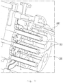
- FIG. 1 is a perspective view showing a gas turbine including a combustor chamber 100, a nozzle can 200, and nozzles 300 according to an exemplary embodiment of the present invention.
- the combustion process of the gas turbine is performed in such a manner that the fuel sprayed in the form of mist through the nozzles 300 and the combustion air required for combustion are supplied to the combustor chamber 100, and the ignition proceeds in the combustor chamber 100.
- the fuel and air may be premixed in an annular space between the nozzles 300 and the nozzle can 200 before being supplied to the combustor chamber 100.
- FIG. 2 is a schematic view showing a gas turbine combustor including a combustor chamber 100 and nozzles 300 according to an embodiment of the conventional art.
- the conventional art is problematic in that there is no internal device capable of controlling the oxygen concentration of the mixture mixed in the premixing space, so the amount of nitrogen oxides in the discharged exhaust gas is considerable. Further, it can also be seen that there is no additional configuration to supply the combustion air in the combustion chamber to the premixing space or to mix the combustion air with premixed air.
- the present invention includes an ejector nozzle and, optionally, at least one bypass path, whereby it is possible to efficiently lower the oxygen concentration in the mixer produced by mixing the fuel sprayed in the form of mist through the nozzles 300 with the combustion air by blowing the combusted air present in the combustor chamber 100 into a premixing space as described in more detail below.
- FIG. 3 is a schematic view showing a gas turbine including a combustor chamber 100 and nozzles 300 according to an exemplary embodiment of the present invention. As shown in FIG. 3 , bypass path 500 is provided to lower the oxygen concentration of the mixer.
- a combustor of a gas turbine includes a flue gas recirculation combustor comprising a combustor chamber 100 configured such that fuel and combustion gas are injected therein to cause combustion, a nozzle-side end with a nozzle can 200 and a plurality of nozzles 300 connected thereto, and a combustor outlet.
- the nozzle can 200 is connected to the nozzle-side end of the combustor chamber 100 and the plurality of nozzles 300 are inserted into the nozzle can 200 and configured such that an injection direction thereof is directed to a side of the combustor chamber 100, wherein a sleeve 400 provided in a premixing space 700 defined between the nozzle can 200 and the nozzle-side end of the combustor chamber 100 is provided with an ejector nozzle and, optionally, at least one bypass path.
- the plurality of nozzles 300 may be arranged to form at least one concentric circle based on a center of the nozzle can 200 having a circular longitudinal section, with the nozzles 300 arranged to be spaced from each other at predetermined intervals in one circular nozzle arrangement. It is preferable that the combustion air and fuel are premixed and injected. Through this nozzle arrangement, it is possible to smoothly mix fuel, air, and fuel/air mixture in the premixing space 700.
- bypass path 500 or the ejector nozzle 600 may be provided through the sleeve 400 arranged between the nozzle can 200 and the nozzle-side end of the combustor chamber 100 connected to the nozzle can 200, with at least one or more thereof provided on an inner surface of the sleeve 400 along a circumferential direction. Further, both the bypass path 500 and the ejector nozzle 600 may be provided through the sleeve 400, with the ejector nozzle 600 provided between one bypass path 500 and neighboring bypass path 500, the bypass path 500 configured such that at least one or more thereof are provided at a predetermined interval on the inner surface of the sleeve 400 along the circumferential direction.
- bypass path 500 on the inner surface of the sleeve 400 along the circumferential direction, or may be possible to provide only the ejector nozzle 600 in the inner surface of the sleeve 400 along the circumferential direction.
- bypass path 500 and the ejector nozzle 600 may be also possible to alternately install the bypass path 500 and the ejector nozzle 600 on the inner surface of the sleeve 400 along the circumferential direction in order to reduce nitrogen oxides.
- bypass path 500 it is possible to obtain a mixing effect due to natural flow resulting from the pressure difference between the combustor chamber 100 and the premixing space 700.
- the ejector nozzle 600 it is possible to control the injection amount using the pressure difference. Therefore, a gas turbine capable of reducing nitrogen oxides at low cost and high efficiency may be achieved by appropriately disposing the ejector nozzle 600.
- bypass path 500 is configured such that a first end thereof is formed in the combustor chamber 100 in which the combustion air is formed at a high pressure, and a second end thereof is formed in the premixing space 700, it is possible to naturally deliver the high-pressure combustion air (i.e., air with a relatively large amount of nitrogen oxides and carbon dioxide) to the premixing space 700. Accordingly, by having such a configuration, it is possible to naturally deliver the high-pressure combustion air to the premixing space 700 without providing a separate driving force.
- the high-pressure combustion air i.e., air with a relatively large amount of nitrogen oxides and carbon dioxide
- FIG. 4 is a longitudinal sectional view showing the ejector nozzle 600 according to an exemplary embodiment of the present invention. Referring to FIG. 4 , an exemplary configuration of an ejector nozzle 600, which is a component of the present invention, self-driven, and capable of injection control, is shown.
- ejector nozzle 600 includes a nozzle casing 610 provided in the sleeve 400 shown in FIG. 3 , an injection control needle assembly 620 provided in the nozzle casing 610, a combustor flow path 630 connecting at least one point of the nozzle casing 610 and a side of the combustor chamber 100, and a premix flow path 640 connecting a side of the nozzle casing 610 and the premixing space 700.
- the nozzle casing 610 may be in a cylindrical shape with an end thereof closed, and the nozzle casing may include a narrowed part 611 provided at an open end of the nozzle casing 610 to inject gases in the combustor chamber 100 to the premixing space 700, and a partition 612 dividing the cylindrical nozzle casing 610 by longitudinally bisecting the same.
- the injection control needle assembly 620 may include a needle 621 longitudinally provided at a center of the cylindrical nozzle casing 610 with an end thereof closed, a movable member 622 provided at an end of the needle 621 to allow the needle 621 to move horizontally along the center of the nozzle casing 610, a first elastic member 623 provided between a partition 612 of the nozzle casing 610 and the movable member 622, a second elastic member 624 provided between the movable member 622 and the closed end of the nozzle casing 610, and an elasticity adjusting member 625 screwed to the closed end of the nozzle casing 610 to be connected to the second elastic member 624.
- the injection control needle assembly 620 may further include at least one ring stopper 626 limiting horizontal movement of the movable member 622 in the nozzle casing 610.
- the combustor flow path 630 is configured such that an inlet end thereof is provided at the nozzle-side end of the combustor chamber 100 and an outlet end thereof is provided at a side of the nozzle casing 610.
- the outlet end includes a combustor pressure path 631 communicating with a space between the partition 612 and the movable member 622, and a recirculation flow path 632 communicating with an injection path 613 in the nozzle casing 610.
- premix flow path 640 is configured such that an inlet end thereof is provided at a nozzle-side end of the sleeve 400 and an outlet end thereof is provided at a side of the nozzle casing 610, with the outlet end communicating with a space between the movable member 622 and the closed end of the nozzle casing 610.
- High pressure combustion air in the combustor chamber 100 naturally enters the combustor flow path 630, and the combustion air naturally entering the combustor flow path 630 splits into the combustor pressure path 631 and the recirculation flow path 632 and is introduced into the nozzle casing 610.
- the combustion air introduced into the nozzle casing 610 through the combustor pressure path 631 provides a force to push the movable member 622 in a direction toward the combustor chamber 100, and when the combustion air is supplied at a predetermined pressure or more, backward movement is restricted by the ringshaped ring stopper 626 provided at least one inside the nozzle casing 610.
- the needle 621 connected to the movable member 622 is also moved backward, and the gap between the narrowed part 611 and the needle 621 is increased, thereby increasing the amount of combustion air injected through the injection path 613.
- most of the combustion air delivered from the combustor chamber 100 through the recirculation flow path 632 is transferred to the premixing space 700.
- forward movement may be restricted by another ring stopper, not shown, provided at least one inside the nozzle casing 610.
- the elasticity adjusting member 625 may also be desirable to provide an elasticity adjusting member 625 that is screwed to the closed end of the nozzle casing 610.
- the elasticity adjusting member 625 is connected to the movable member 622 via the second elastic member 624, wherein by rotating the elasticity adjusting member 625 to adjust the preload of the second elastic member 624, it is possible to adjust the operational sensitivity of the movable member 622 in response to the pressure of the combustion air introduced into the nozzle casing 610 and the pressure of the premixed air introduced into the combustor chamber 100.
Description
- The present patent claims priority to Korean Patent Application No.
10-2016-0175823, filed December 21, 2016 - The present disclosure relates generally to a gas turbine. More particularly, the present disclosure relates to a turbine including a flue gas recirculation combustor, wherein NOx (nitrogen oxides) is reduced by recirculating the flue gas to lower the oxygen concentration of premixed fuel (mixture of mist fuel and air) in a combustor chamber that combusts the premixed fuel of fuel and air (mixture of mist fuel and air) injected from a nozzle, NOx (nitrogen oxides) can be reduced by recirculating the flue gas to lower the oxygen concentration in the premixed fuel.
- A gas turbine is a rotary type heat engine that drives a turbine with high temperature and high pressure combustion gas. To create the high-temperature and high-pressure combustion gas, a mixture of fuel and air injected from the combustion nozzle must be combusted in the combustion chamber provided in the combustor. While combustion continues, the gas turbine continues to operate until fuel and air supply (especially, the fuel supply) is stopped.
- In the gas turbine, self-sustaining combustion of fuel/air mixture supplied to the combustion chamber by the heat generated occurs only when the initial combustion of the fuel/air mixture is initiated and a high temperature environment is created in the combustion chamber.Accordingly, in order to operate a stopped gas turbine, an igniter is used to generate an artificial combustion for the initial mixture.
- The igniter may be of the type that emits electrical energy or uses electrical energy to heat an end portion thereof, or it may be of an ignition torch type that burns the fuel.
- The fuel/air mixture combusted in the combustor chamber emits a large amount of nitrogen oxides (NOx).In this case, nitrogen oxides, as pollutants, must be reduced to avoid environmental pollution. To achieve this, a method of suppressing the generation of nitrogen oxides by reducing the oxygen concentration contained in the combusting fuel/air mixture can be used.
US 4130388 A presents a fuel burner that includes a combustion zone into which is directly fed the combustion air. Air-atomized liquid fuel is fed into the combustion zone through a Venturi whose constricted throat communicates by way of a feedback passage to the combustion zone. The ejector effect produced by the atomized fuel passing through the Venturi causes a portion of the hot combustion gas generated in the combustion zone to be drawn into the throat to intermix with the atomized fuel therein, thereby pre-vaporizing the fuel to insure full combustion thereof.US 4130388 A provides the basis for the two-part form of claim 1.US 4575332 A ,US 2002/187449 A1 andUS 2015/369126 A1 also present combustor systems where exhaust gases from combustor chamber are fed into the burner interior or flame initiation point. - In the combustion process of a conventional gas turbine, the temperature of the combustion process is controlled to limit the emission of nitrogen oxides. However, it is very difficult to control the oxygen concentration only with an internal device of the gas turbine. As a result, the efficiency of reducing the nitrogen oxide concentration is low. Accordingly, securing the effect of sufficiently reducing the nitrogen oxide concentration only by the conventional structure has been problematic, so structural improvement is needed.
- The present invention provides a solution to the above problems occurring in the related art. An object of the present invention is to provide a gas turbine, which is operated by igniting a mixture of fuel and air injected into a combustion chamber thereof, having an ejector nozzle, and optionally a bypass path, at a side of the combustor chamber to lower the oxygen concentration of fuel.
- To achieve the above object, in an aspect of the present invention, there is provided a flue gas recirculation combustor in accordance with claim 1.
- Herein, the plurality of nozzles may be arranged to form at least one concentric circle based on a center of the nozzle can having a circular longitudinal section, with the nozzles arranged to be spaced from each other at predetermined intervals in one circular nozzle arrangement.
- Further, the plurality of nozzles may be configured such that combustion air and fuel are premixed therein and injected therefrom.
- Still further, the bypass path or the ejector nozzle may be provided through the sleeve arranged between the nozzle can and the nozzle-side end of the combustor chamber connected to the nozzle can, with at least one or more thereof provided on an inner surface of the sleeve along a circumferential direction.
- Herein, both the bypass path and the ejector nozzle may be provided through the sleeve, with the ejector nozzle provided between one bypass path and neighboring bypass path, the bypass path being configured such that at least one or more thereof are provided at a predetermined interval on the inner surface of the sleeve along the circumferential direction.
- The nozzle casing may be in a cylindrical shape with an end thereof closed, and the nozzle casing may include a narrowed part provided at an open end of the nozzle casing to inject gases in the combustor chamber to the premixing space, and a partition dividing the cylindrical nozzle casing by longitudinally bisecting the same.
- The injection control needle assembly may include a needle longitudinally provided at a center of the cylindrical nozzle casing with an end thereof closed, a movable member provided at an end of the needle to allow the needle to move horizontally along the center of the nozzle casing, a first elastic member provided between the partition of the nozzle casing and the movable member, and a second elastic member provided between the movable member and the closed end of the nozzle casing.
- The injection control needle assembly may further include an elasticity adjusting member screwed to the closed end of the nozzle casing to be connected to the second elastic member.
- The injection control needle assembly may further include at least one ring stopper limiting horizontal movement of the movable member in the nozzle casing.
- Further, the combustor flow path may be configured such that an inlet end thereof is provided at the nozzle-side end of the combustor chamber and an outlet end thereof is provided at a side of the nozzle casing, and the outlet end includes a combustor pressure path communicating with a space between the partition and the movable member, and a recirculation flow path communicating with an injection path in the nozzle casing.
- Still further, the premix flow path may be configured such that an inlet end thereof is provided at a nozzle-side end of the sleeve and an outlet end thereof is provided at a side of the nozzle casing, with the outlet end communicating with a space between the movable member and the closed end of the nozzle casing.
- According to a turbine including a flue gas recirculation combustor of the present disclosure configured as described above, it is possible to reduce the amount of nitrogen oxides (NOx) contained in the exhaust gas.
- In particular, the premixing space provided between a plurality of nozzles and the combustor chamber, and the bypass path or the ejector nozzle provided in the sleeve are configured such that their shapes and installation positions have optimum efficiency and are self-driven.
- Accordingly, by providing a turbine including the bypass path or the ejector nozzle configured as described above, it is possible to reduce the amount of nitrogen oxides (NOx) contained in the exhaust gas regardless of the combustion temperature.
- The above and other objects, features and other advantages of the present invention will be more clearly understood from the following detailed description when taken in conjunction with the accompanying drawings, in which:
-
FIG. 1 is a perspective view showing an exemplary embodiment of a gas turbine combustor including a combustor chamber, nozzles, and a nozzle can; -
FIG. 2 is a schematic view showing a conventional gas turbine combustor including a combustor chamber and nozzles; -
FIG. 3 is a schematic view showing an exemplary embodiment of a gas turbine combustor including a combustor chamber and nozzles; and -
FIG. 4 is a longitudinal sectional view showing an exemplary embodiment of an ejector nozzle. - Hereinbelow, exemplary embodiments of the present invention will be described in detail with reference to the accompanying drawings.
- The terminology used herein is for the purpose of describing particular embodiments only and is not intended to be limiting. As used herein, the singular forms "a", "an", and "the" are intended to include the plural forms as well, unless the context clearly indicates otherwise. It will be further understood that the terms "comprise", "include", "have", etc. when used in this specification, specify the presence of stated features, integers, steps, operations, elements, components, and/or combinations of them but do not preclude the presence or addition of one or more other features, integers, steps, operations, elements, components, and/or combinations thereof.
- It will be further understood that, although the terms first, second, etc. may be used herein to describe various elements, these elements should not be limited by these terms. These terms are only used to distinguish one element from another.
- Also, the terms "∼ part", "∼ unit", "module", "apparatus" and the like mean a unit for processing at least one function or operation and may be implemented by a combination of hardware and/or software.
- It should be noted that the same reference numerals are used to designate the same or similar elements throughout the drawings. In the following description of the present invention, detailed descriptions of known functions and configurations which are deemed to make the gist of the present disclosure obscure will be omitted.
- Hereinbelow, the terms used in describing the present invention are simply defined as follows.
-
FIG. 1 is a perspective view showing a gas turbine including acombustor chamber 100, a nozzle can 200, andnozzles 300 according to an exemplary embodiment of the present invention. The combustion process of the gas turbine is performed in such a manner that the fuel sprayed in the form of mist through thenozzles 300 and the combustion air required for combustion are supplied to thecombustor chamber 100, and the ignition proceeds in thecombustor chamber 100. Depending on the embodiment, the fuel and air may be premixed in an annular space between thenozzles 300 and the nozzle can 200 before being supplied to thecombustor chamber 100. -
FIG. 2 is a schematic view showing a gas turbine combustor including acombustor chamber 100 andnozzles 300 according to an embodiment of the conventional art. As shown inFIG. 2 , the conventional art is problematic in that there is no internal device capable of controlling the oxygen concentration of the mixture mixed in the premixing space, so the amount of nitrogen oxides in the discharged exhaust gas is considerable. Further, it can also be seen that there is no additional configuration to supply the combustion air in the combustion chamber to the premixing space or to mix the combustion air with premixed air. - In this case, as described above, nitrogen oxides (NOx) are generated in the combustion process. The present invention includes an ejector nozzle and, optionally, at least one bypass path, whereby it is possible to efficiently lower the oxygen concentration in the mixer produced by mixing the fuel sprayed in the form of mist through the
nozzles 300 with the combustion air by blowing the combusted air present in thecombustor chamber 100 into a premixing space as described in more detail below. -
FIG. 3 is a schematic view showing a gas turbine including acombustor chamber 100 andnozzles 300 according to an exemplary embodiment of the present invention. As shown inFIG. 3 ,bypass path 500 is provided to lower the oxygen concentration of the mixer. - More specifically, a combustor of a gas turbine according to an exemplary embodiment includes a flue gas recirculation combustor comprising a
combustor chamber 100 configured such that fuel and combustion gas are injected therein to cause combustion, a nozzle-side end with a nozzle can 200 and a plurality ofnozzles 300 connected thereto, and a combustor outlet. The nozzle can 200 is connected to the nozzle-side end of thecombustor chamber 100 and the plurality ofnozzles 300 are inserted into the nozzle can 200 and configured such that an injection direction thereof is directed to a side of thecombustor chamber 100, wherein asleeve 400 provided in apremixing space 700 defined between the nozzle can 200 and the nozzle-side end of thecombustor chamber 100 is provided with an ejector nozzle and, optionally, at least one bypass path. - In this case, the plurality of
nozzles 300 may be arranged to form at least one concentric circle based on a center of the nozzle can 200 having a circular longitudinal section, with thenozzles 300 arranged to be spaced from each other at predetermined intervals in one circular nozzle arrangement. It is preferable that the combustion air and fuel are premixed and injected. Through this nozzle arrangement, it is possible to smoothly mix fuel, air, and fuel/air mixture in thepremixing space 700. - Further, the
bypass path 500 or theejector nozzle 600 may be provided through thesleeve 400 arranged between the nozzle can 200 and the nozzle-side end of thecombustor chamber 100 connected to the nozzle can 200, with at least one or more thereof provided on an inner surface of thesleeve 400 along a circumferential direction. Further, both thebypass path 500 and theejector nozzle 600 may be provided through thesleeve 400, with theejector nozzle 600 provided between onebypass path 500 and neighboringbypass path 500, thebypass path 500 configured such that at least one or more thereof are provided at a predetermined interval on the inner surface of thesleeve 400 along the circumferential direction. - It may be possible to provide only the
bypass path 500 on the inner surface of thesleeve 400 along the circumferential direction, or may be possible to provide only theejector nozzle 600 in the inner surface of thesleeve 400 along the circumferential direction. - It may be also possible to alternately install the
bypass path 500 and theejector nozzle 600 on the inner surface of thesleeve 400 along the circumferential direction in order to reduce nitrogen oxides. - Using the
bypass path 500, it is possible to obtain a mixing effect due to natural flow resulting from the pressure difference between thecombustor chamber 100 and thepremixing space 700. However, in the case of theejector nozzle 600 according to an exemplary embodiment of the present invention, it is possible to control the injection amount using the pressure difference. Therefore, a gas turbine capable of reducing nitrogen oxides at low cost and high efficiency may be achieved by appropriately disposing theejector nozzle 600. - Since the
bypass path 500 is configured such that a first end thereof is formed in thecombustor chamber 100 in which the combustion air is formed at a high pressure, and a second end thereof is formed in thepremixing space 700, it is possible to naturally deliver the high-pressure combustion air (i.e., air with a relatively large amount of nitrogen oxides and carbon dioxide) to thepremixing space 700. Accordingly, by having such a configuration, it is possible to naturally deliver the high-pressure combustion air to thepremixing space 700 without providing a separate driving force. - Next, an exemplary configuration of a self-driven
ejector nozzle 600 that may be included in the present invention will be described in detail. -
FIG. 4 is a longitudinal sectional view showing theejector nozzle 600 according to an exemplary embodiment of the present invention. Referring toFIG. 4 , an exemplary configuration of anejector nozzle 600, which is a component of the present invention, self-driven, and capable of injection control, is shown. - More specifically,
ejector nozzle 600 includes anozzle casing 610 provided in thesleeve 400 shown inFIG. 3 , an injectioncontrol needle assembly 620 provided in thenozzle casing 610, acombustor flow path 630 connecting at least one point of thenozzle casing 610 and a side of thecombustor chamber 100, and apremix flow path 640 connecting a side of thenozzle casing 610 and thepremixing space 700. - In this case, the
nozzle casing 610 may be in a cylindrical shape with an end thereof closed, and the nozzle casing may include anarrowed part 611 provided at an open end of thenozzle casing 610 to inject gases in thecombustor chamber 100 to thepremixing space 700, and apartition 612 dividing thecylindrical nozzle casing 610 by longitudinally bisecting the same. - Further, the injection
control needle assembly 620 may include aneedle 621 longitudinally provided at a center of thecylindrical nozzle casing 610 with an end thereof closed, amovable member 622 provided at an end of theneedle 621 to allow theneedle 621 to move horizontally along the center of thenozzle casing 610, a firstelastic member 623 provided between apartition 612 of thenozzle casing 610 and themovable member 622, a secondelastic member 624 provided between themovable member 622 and the closed end of thenozzle casing 610, and anelasticity adjusting member 625 screwed to the closed end of thenozzle casing 610 to be connected to the secondelastic member 624. - Herein, the injection
control needle assembly 620 may further include at least onering stopper 626 limiting horizontal movement of themovable member 622 in thenozzle casing 610. - Further, the
combustor flow path 630 is configured such that an inlet end thereof is provided at the nozzle-side end of thecombustor chamber 100 and an outlet end thereof is provided at a side of thenozzle casing 610. In particular, the outlet end includes acombustor pressure path 631 communicating with a space between thepartition 612 and themovable member 622, and arecirculation flow path 632 communicating with aninjection path 613 in thenozzle casing 610. - In addition, the
premix flow path 640 is configured such that an inlet end thereof is provided at a nozzle-side end of thesleeve 400 and an outlet end thereof is provided at a side of thenozzle casing 610, with the outlet end communicating with a space between themovable member 622 and the closed end of thenozzle casing 610. - High pressure combustion air in the
combustor chamber 100 naturally enters thecombustor flow path 630, and the combustion air naturally entering thecombustor flow path 630 splits into thecombustor pressure path 631 and therecirculation flow path 632 and is introduced into thenozzle casing 610. The combustion air introduced into thenozzle casing 610 through thecombustor pressure path 631 provides a force to push themovable member 622 in a direction toward thecombustor chamber 100, and when the combustion air is supplied at a predetermined pressure or more, backward movement is restricted by theringshaped ring stopper 626 provided at least one inside thenozzle casing 610. - When a force pushing the
movable member 622 toward thecombustor chamber 100 is applied, theneedle 621 connected to themovable member 622 is also moved backward, and the gap between thenarrowed part 611 and theneedle 621 is increased, thereby increasing the amount of combustion air injected through theinjection path 613. In this case, most of the combustion air delivered from thecombustor chamber 100 through therecirculation flow path 632 is transferred to thepremixing space 700. - On the same principle, when the pressure of the premixed air introduced into the
combustor chamber 100 is higher than the pressure of the combustion air introduced into thenozzle casing 610, a force pushing themovable member 622 in the direction of thepremixing space 700 is applied, and in this case, theneedle 621 connected to themovable member 622 is also moved forward. Accordingly, the gap between thenarrowed part 611 and theneedle 621 is reduced, whereby the amount of combustion air injected through theinjection path 613 is reduced. - Also in this case, when the premixed air is supplied at a predetermined pressure or more, forward movement may be restricted by another ring stopper, not shown, provided at least one inside the
nozzle casing 610. - It may also be desirable to provide an
elasticity adjusting member 625 that is screwed to the closed end of thenozzle casing 610. Theelasticity adjusting member 625 is connected to themovable member 622 via the secondelastic member 624, wherein by rotating theelasticity adjusting member 625 to adjust the preload of the secondelastic member 624, it is possible to adjust the operational sensitivity of themovable member 622 in response to the pressure of the combustion air introduced into thenozzle casing 610 and the pressure of the premixed air introduced into thecombustor chamber 100. - It shoutd be understood that the embodiments disclosed in the present disclosure are not restrictive but are illustrative, and the scope of the technical idea of the present invention is not limited to the disclosed exemplary embodiments. Accordingly, the scope of the present invention should be interpreted by the accompanying claims. Further, it is to be understood that various alternatives, modifications, and equivalents fall within the scope of the present invention as defined by the appended claims.
Claims (11)
- A flue gas recirculation combustor comprising:a combustor chamber (100) configured to receive fuel and combustion gas to cause combustion, the combustor chamber (100) including a nozzle-side end and a combustor outlet;a nozzle can (200) connected to the nozzle-side end of the combustor chamber (100);a plurality of nozzles (300) disposed in the nozzle can (200) and arranged such that an injection direction thereof is directed to a side of the combustor chamber (100); anda sleeve (400) disposed in a premixing space defined between the nozzle can (200) and the nozzle-side end of the combustor chamber (100), the sleeve (400) including a recirculation pathway to recirculate combustion air from the combustor chamber (100) to the premixing space (700),
characterized in that
the recirculation pathway includes an ejector nozzle (600), wherein the ejector nozzle (600) includesa nozzle casing (610),an injection control needle assembly (620) disposed in the nozzle casing (610),a combustor flow path (630) connecting at least one point of the nozzle casing (610) and the nozzle-side end of the combustor chamber (100), anda premix flow path (640) connecting a side of the nozzle casing (610) and the premixing space (700). - The flue gas recirculation combustor of claim 1, wherein the recirculation pathway includes at least one bypass path (500).
- The flue gas recirculation combustor of claim 1 or 2, wherein the plurality of nozzles (300) is configured to premix and inject combustion air and fuel.
- The flue gas recirculation combustor of claim 1, 2 or 3, wherein the recirculation pathway is provided on an inner surface of the sleeve (400) along a circumferential direction.
- The flue gas recirculation combustor of claim 4, wherein the recirculation pathway includes at least two bypass paths (500), wherein the bypass paths (500) and the ejector nozzle (600) are present alternately on the inner surface of the sleeve (400) along the circumferential direction.
- The flue gas recirculation combustor of claim 1, wherein the nozzle casing (610) has a closed end, the nozzle casing (610) including
a narrowed portion (611) provided at an open end of the nozzle casing (610) to inject gases from the combustor chamber (100) to the premixing space (700), and
a partition (612) longitudinally dividing the nozzle casing (610). - The flue gas recirculation combustor of claim 6, wherein the injection control needle assembly (620) includes
a needle (621) arranged longitudinally at a center of the nozzle casing (610),
a movable member (622) arranged at an end of the needle (621) to move the needle (621) horizontally along the center of the nozzle casing (610),
a first elastic member (623) arranged between the partition (612) of the nozzle casing (610) and the movable member (622), and
a second elastic member (624) provided between the movable member (622) and the closed end of the nozzle casing (610). - The flue gas recirculation combustor of claim 7, wherein the injection control needle assembly (620) further includes an elasticity adjusting member (625) arranged at the closed end of the nozzle casing (610) to be connected to the second elastic member (624).
- The flue gas recirculation combustor of claim 7 or 8, wherein the injection control needle assembly (620) further includes at least one ring stopper (626) to limit horizontal movement of the movable member (622) in the nozzle casing (610).
- The flue gas recirculation combustor of any one of claims 7 to 9, wherein an inlet end of the combustor flow path (630) is connected to the nozzle-side end of the combustor chamber (100) and an outlet end of the combustor flow path (630) is connected to a side of the nozzle casing (610), the outlet end including
a combustor pressure path (631) communicating with a space between the partition (612) and the movable member (622), and
a recirculation flow path (632) communicating with an injection path (613) in the nozzle casing (610). - The flue gas recirculation combustor of any one of claims 7 to 10, wherein an inlet end of the premix flow path (640) is provided at a nozzle-side end of the sleeve (400) and an outlet end of the premix flow path (640) is provided at a side of the nozzle casing (610) and in communication with a space between the movable member (622) and the closed end of the nozzle casing (610).
Applications Claiming Priority (1)
| Application Number | Priority Date | Filing Date | Title |
|---|---|---|---|
| KR1020160175823A KR101931968B1 (en) | 2016-12-21 | 2016-12-21 | Turbines including flue gas recirculation combustors. |
Publications (2)
| Publication Number | Publication Date |
|---|---|
| EP3339738A1 EP3339738A1 (en) | 2018-06-27 |
| EP3339738B1 true EP3339738B1 (en) | 2020-07-08 |
Family
ID=60450455
Family Applications (1)
| Application Number | Title | Priority Date | Filing Date |
|---|---|---|---|
| EP17202951.4A Active EP3339738B1 (en) | 2016-12-21 | 2017-11-22 | Turbine including fuel gas recirculation combustor |
Country Status (4)
| Country | Link |
|---|---|
| US (1) | US10590847B2 (en) |
| EP (1) | EP3339738B1 (en) |
| JP (1) | JP6470383B2 (en) |
| KR (1) | KR101931968B1 (en) |
Families Citing this family (3)
| Publication number | Priority date | Publication date | Assignee | Title |
|---|---|---|---|---|
| JP7245490B2 (en) * | 2018-08-08 | 2023-03-24 | 株式会社ヒラカワ | Steam generating method and steam generating apparatus |
| JP2022190447A (en) * | 2021-06-14 | 2022-12-26 | 東芝エネルギーシステムズ株式会社 | Burner for torch ignition mechanism and operating method for the same |
| CN114856827B (en) * | 2022-05-12 | 2023-06-30 | 中国航发四川燃气涡轮研究院 | Detachable fan-shaped nozzle capable of adjusting nozzle position and spraying direction |
Family Cites Families (18)
| Publication number | Priority date | Publication date | Assignee | Title |
|---|---|---|---|---|
| JPS51118126A (en) | 1975-04-10 | 1976-10-16 | Kawasaki Heavy Ind Ltd | Combustion apparatus with abgas cycling instrument |
| US4130388A (en) * | 1976-09-15 | 1978-12-19 | Flynn Burner Corporation | Non-contaminating fuel burner |
| US4160526A (en) | 1977-03-24 | 1979-07-10 | Flynn Burner Corporation | Liquid fuel atomizing nozzle |
| DE3327597A1 (en) | 1983-07-30 | 1985-02-07 | Deutsche Babcock Werke AG, 4200 Oberhausen | METHOD AND BURNER FOR BURNING LIQUID OR GASEOUS FUELS WITH REDUCED NOX PRODUCTION |
| JPS6193315A (en) * | 1984-10-15 | 1986-05-12 | Hitachi Ltd | Gas turbine fuel ejector |
| JPS6485861A (en) | 1987-09-28 | 1989-03-30 | Sumitomo Electric Industries | Proportional control valve for antilock device |
| JPH10160163A (en) | 1996-11-22 | 1998-06-19 | Ishikawajima Harima Heavy Ind Co Ltd | Nitrogen oxide reduction structure of gas turbine combustor |
| JPH11132404A (en) | 1997-10-31 | 1999-05-21 | Miura Co Ltd | Water-tube boiler |
| EP1262714A1 (en) | 2001-06-01 | 2002-12-04 | ALSTOM (Switzerland) Ltd | Burner with exhausts recirculation |
| JP2005061256A (en) | 2003-08-08 | 2005-03-10 | Komatsu Ltd | Exhaust gas recirculation system and turbo compound engine equipped therewith |
| JP5190177B2 (en) * | 2005-12-01 | 2013-04-24 | 太一 稲田 | Pressure flow proportional control valve |
| JP2009127951A (en) | 2007-11-26 | 2009-06-11 | Hitachi Ltd | Gas turbine combustor |
| JP2009198148A (en) | 2008-02-25 | 2009-09-03 | Mitsubishi Heavy Ind Ltd | Combustor |
| US20110167828A1 (en) * | 2010-01-08 | 2011-07-14 | Arjun Singh | Combustor assembly for a turbine engine that mixes combustion products with purge air |
| JP5156066B2 (en) | 2010-08-27 | 2013-03-06 | 株式会社日立製作所 | Gas turbine combustor |
| JP6004976B2 (en) | 2013-03-21 | 2016-10-12 | 三菱重工業株式会社 | Combustor and gas turbine |
| EP2957835B1 (en) | 2014-06-18 | 2018-03-21 | Ansaldo Energia Switzerland AG | Method for recirculation of exhaust gas from a combustion chamber of a combustor of a gas turbine and gas turbine for conducting said method |
| KR101583509B1 (en) * | 2014-10-23 | 2016-01-13 | 한국생산기술연구원 | A Burner for generating reduced nitrogen oxide |
-
2016
- 2016-12-21 KR KR1020160175823A patent/KR101931968B1/en active IP Right Grant
-
2017
- 2017-11-14 US US15/812,898 patent/US10590847B2/en active Active
- 2017-11-14 JP JP2017218750A patent/JP6470383B2/en active Active
- 2017-11-22 EP EP17202951.4A patent/EP3339738B1/en active Active
Non-Patent Citations (1)
| Title |
|---|
| None * |
Also Published As
| Publication number | Publication date |
|---|---|
| JP6470383B2 (en) | 2019-02-13 |
| KR101931968B1 (en) | 2018-12-24 |
| US20180171869A1 (en) | 2018-06-21 |
| EP3339738A1 (en) | 2018-06-27 |
| US10590847B2 (en) | 2020-03-17 |
| JP2018100824A (en) | 2018-06-28 |
| KR20180072348A (en) | 2018-06-29 |
Similar Documents
| Publication | Publication Date | Title |
|---|---|---|
| EP2481982B2 (en) | Mixer assembly for a gas turbine engine | |
| EP1985927B1 (en) | Gas turbine combustor system with lean-direct injection for reducing NOx emissions | |
| KR101470774B1 (en) | Nozzle, gas turbine combustor and gas turbine | |
| CN106796031B (en) | Torch type igniter | |
| US10480791B2 (en) | Fuel injector to facilitate reduced NOx emissions in a combustor system | |
| US6374615B1 (en) | Low cost, low emissions natural gas combustor | |
| US10718524B2 (en) | Mixer assembly for a gas turbine engine | |
| KR20150065820A (en) | Flamesheet cumbustor dome | |
| JP6196868B2 (en) | Fuel nozzle and its assembly method | |
| CN103089453A (en) | Apparatus for head end direct air injection with enhanced mixing capabilities | |
| EP3339738B1 (en) | Turbine including fuel gas recirculation combustor | |
| KR20200027894A (en) | Gas turbine combustor | |
| EP1835231A1 (en) | Burner in particular for a gas turbine combustor, and method of operating a burner | |
| US20160201918A1 (en) | Small arrayed swirler system for reduced emissions and noise | |
| KR20160069805A (en) | Fuel nozzle for combustor | |
| JP4400314B2 (en) | Gas turbine combustor and fuel supply method for gas turbine combustor | |
| EP2932155A1 (en) | Air directed fuel injection | |
| US9677766B2 (en) | Fuel nozzle for use in a turbine engine and method of assembly | |
| KR200421616Y1 (en) | LOW NOx GAS BURNER | |
| KR20170006209A (en) | Combustor | |
| JP6039033B2 (en) | Gas turbine combustor | |
| EP1793170A2 (en) | Opposed flow combustor | |
| US20130276450A1 (en) | Combustor apparatus for stoichiometric combustion | |
| JP5982169B2 (en) | Gas turbine combustor | |
| EP3043116A1 (en) | Mixer assembly for a gas turbine engine |
Legal Events
| Date | Code | Title | Description |
|---|---|---|---|
| PUAI | Public reference made under article 153(3) epc to a published international application that has entered the european phase |
Free format text: ORIGINAL CODE: 0009012 |
|
| STAA | Information on the status of an ep patent application or granted ep patent |
Free format text: STATUS: REQUEST FOR EXAMINATION WAS MADE |
|
| 17P | Request for examination filed |
Effective date: 20171122 |
|
| AK | Designated contracting states |
Kind code of ref document: A1 Designated state(s): AL AT BE BG CH CY CZ DE DK EE ES FI FR GB GR HR HU IE IS IT LI LT LU LV MC MK MT NL NO PL PT RO RS SE SI SK SM TR |
|
| AX | Request for extension of the european patent |
Extension state: BA ME |
|
| RBV | Designated contracting states (corrected) |
Designated state(s): AL AT BE BG CH CY CZ DE DK EE ES FI FR GB GR HR HU IE IS IT LI LT LU LV MC MK MT NL NO PL PT RO RS SE SI SK SM TR |
|
| RAP1 | Party data changed (applicant data changed or rights of an application transferred) |
Owner name: DOOSAN HEAVY INDUSTRIES & CONSTRUCTION CO., LTD. |
|
| GRAP | Despatch of communication of intention to grant a patent |
Free format text: ORIGINAL CODE: EPIDOSNIGR1 |
|
| STAA | Information on the status of an ep patent application or granted ep patent |
Free format text: STATUS: GRANT OF PATENT IS INTENDED |
|
| INTG | Intention to grant announced |
Effective date: 20200210 |
|
| GRAS | Grant fee paid |
Free format text: ORIGINAL CODE: EPIDOSNIGR3 |
|
| GRAA | (expected) grant |
Free format text: ORIGINAL CODE: 0009210 |
|
| STAA | Information on the status of an ep patent application or granted ep patent |
Free format text: STATUS: THE PATENT HAS BEEN GRANTED |
|
| AK | Designated contracting states |
Kind code of ref document: B1 Designated state(s): AL AT BE BG CH CY CZ DE DK EE ES FI FR GB GR HR HU IE IS IT LI LT LU LV MC MK MT NL NO PL PT RO RS SE SI SK SM TR |
|
| REG | Reference to a national code |
Ref country code: CH Ref legal event code: EP Ref country code: AT Ref legal event code: REF Ref document number: 1288866 Country of ref document: AT Kind code of ref document: T Effective date: 20200715 |
|
| REG | Reference to a national code |
Ref country code: DE Ref legal event code: R096 Ref document number: 602017019300 Country of ref document: DE |
|
| REG | Reference to a national code |
Ref country code: IE Ref legal event code: FG4D |
|
| REG | Reference to a national code |
Ref country code: LT Ref legal event code: MG4D |
|
| REG | Reference to a national code |
Ref country code: AT Ref legal event code: MK05 Ref document number: 1288866 Country of ref document: AT Kind code of ref document: T Effective date: 20200708 |
|
| REG | Reference to a national code |
Ref country code: NL Ref legal event code: MP Effective date: 20200708 |
|
| PG25 | Lapsed in a contracting state [announced via postgrant information from national office to epo] |
Ref country code: BG Free format text: LAPSE BECAUSE OF FAILURE TO SUBMIT A TRANSLATION OF THE DESCRIPTION OR TO PAY THE FEE WITHIN THE PRESCRIBED TIME-LIMIT Effective date: 20201008 Ref country code: SE Free format text: LAPSE BECAUSE OF FAILURE TO SUBMIT A TRANSLATION OF THE DESCRIPTION OR TO PAY THE FEE WITHIN THE PRESCRIBED TIME-LIMIT Effective date: 20200708 Ref country code: GR Free format text: LAPSE BECAUSE OF FAILURE TO SUBMIT A TRANSLATION OF THE DESCRIPTION OR TO PAY THE FEE WITHIN THE PRESCRIBED TIME-LIMIT Effective date: 20201009 Ref country code: LT Free format text: LAPSE BECAUSE OF FAILURE TO SUBMIT A TRANSLATION OF THE DESCRIPTION OR TO PAY THE FEE WITHIN THE PRESCRIBED TIME-LIMIT Effective date: 20200708 Ref country code: PT Free format text: LAPSE BECAUSE OF FAILURE TO SUBMIT A TRANSLATION OF THE DESCRIPTION OR TO PAY THE FEE WITHIN THE PRESCRIBED TIME-LIMIT Effective date: 20201109 Ref country code: ES Free format text: LAPSE BECAUSE OF FAILURE TO SUBMIT A TRANSLATION OF THE DESCRIPTION OR TO PAY THE FEE WITHIN THE PRESCRIBED TIME-LIMIT Effective date: 20200708 Ref country code: HR Free format text: LAPSE BECAUSE OF FAILURE TO SUBMIT A TRANSLATION OF THE DESCRIPTION OR TO PAY THE FEE WITHIN THE PRESCRIBED TIME-LIMIT Effective date: 20200708 Ref country code: FI Free format text: LAPSE BECAUSE OF FAILURE TO SUBMIT A TRANSLATION OF THE DESCRIPTION OR TO PAY THE FEE WITHIN THE PRESCRIBED TIME-LIMIT Effective date: 20200708 Ref country code: NO Free format text: LAPSE BECAUSE OF FAILURE TO SUBMIT A TRANSLATION OF THE DESCRIPTION OR TO PAY THE FEE WITHIN THE PRESCRIBED TIME-LIMIT Effective date: 20201008 Ref country code: AT Free format text: LAPSE BECAUSE OF FAILURE TO SUBMIT A TRANSLATION OF THE DESCRIPTION OR TO PAY THE FEE WITHIN THE PRESCRIBED TIME-LIMIT Effective date: 20200708 |
|
| PG25 | Lapsed in a contracting state [announced via postgrant information from national office to epo] |
Ref country code: RS Free format text: LAPSE BECAUSE OF FAILURE TO SUBMIT A TRANSLATION OF THE DESCRIPTION OR TO PAY THE FEE WITHIN THE PRESCRIBED TIME-LIMIT Effective date: 20200708 Ref country code: PL Free format text: LAPSE BECAUSE OF FAILURE TO SUBMIT A TRANSLATION OF THE DESCRIPTION OR TO PAY THE FEE WITHIN THE PRESCRIBED TIME-LIMIT Effective date: 20200708 Ref country code: LV Free format text: LAPSE BECAUSE OF FAILURE TO SUBMIT A TRANSLATION OF THE DESCRIPTION OR TO PAY THE FEE WITHIN THE PRESCRIBED TIME-LIMIT Effective date: 20200708 Ref country code: IS Free format text: LAPSE BECAUSE OF FAILURE TO SUBMIT A TRANSLATION OF THE DESCRIPTION OR TO PAY THE FEE WITHIN THE PRESCRIBED TIME-LIMIT Effective date: 20201108 |
|
| PG25 | Lapsed in a contracting state [announced via postgrant information from national office to epo] |
Ref country code: NL Free format text: LAPSE BECAUSE OF FAILURE TO SUBMIT A TRANSLATION OF THE DESCRIPTION OR TO PAY THE FEE WITHIN THE PRESCRIBED TIME-LIMIT Effective date: 20200708 |
|
| REG | Reference to a national code |
Ref country code: DE Ref legal event code: R097 Ref document number: 602017019300 Country of ref document: DE |
|
| PG25 | Lapsed in a contracting state [announced via postgrant information from national office to epo] |
Ref country code: IT Free format text: LAPSE BECAUSE OF FAILURE TO SUBMIT A TRANSLATION OF THE DESCRIPTION OR TO PAY THE FEE WITHIN THE PRESCRIBED TIME-LIMIT Effective date: 20200708 Ref country code: EE Free format text: LAPSE BECAUSE OF FAILURE TO SUBMIT A TRANSLATION OF THE DESCRIPTION OR TO PAY THE FEE WITHIN THE PRESCRIBED TIME-LIMIT Effective date: 20200708 Ref country code: SM Free format text: LAPSE BECAUSE OF FAILURE TO SUBMIT A TRANSLATION OF THE DESCRIPTION OR TO PAY THE FEE WITHIN THE PRESCRIBED TIME-LIMIT Effective date: 20200708 Ref country code: RO Free format text: LAPSE BECAUSE OF FAILURE TO SUBMIT A TRANSLATION OF THE DESCRIPTION OR TO PAY THE FEE WITHIN THE PRESCRIBED TIME-LIMIT Effective date: 20200708 Ref country code: DK Free format text: LAPSE BECAUSE OF FAILURE TO SUBMIT A TRANSLATION OF THE DESCRIPTION OR TO PAY THE FEE WITHIN THE PRESCRIBED TIME-LIMIT Effective date: 20200708 Ref country code: CZ Free format text: LAPSE BECAUSE OF FAILURE TO SUBMIT A TRANSLATION OF THE DESCRIPTION OR TO PAY THE FEE WITHIN THE PRESCRIBED TIME-LIMIT Effective date: 20200708 |
|
| PLBE | No opposition filed within time limit |
Free format text: ORIGINAL CODE: 0009261 |
|
| STAA | Information on the status of an ep patent application or granted ep patent |
Free format text: STATUS: NO OPPOSITION FILED WITHIN TIME LIMIT |
|
| PG25 | Lapsed in a contracting state [announced via postgrant information from national office to epo] |
Ref country code: AL Free format text: LAPSE BECAUSE OF FAILURE TO SUBMIT A TRANSLATION OF THE DESCRIPTION OR TO PAY THE FEE WITHIN THE PRESCRIBED TIME-LIMIT Effective date: 20200708 |
|
| 26N | No opposition filed |
Effective date: 20210409 |
|
| PG25 | Lapsed in a contracting state [announced via postgrant information from national office to epo] |
Ref country code: SK Free format text: LAPSE BECAUSE OF FAILURE TO SUBMIT A TRANSLATION OF THE DESCRIPTION OR TO PAY THE FEE WITHIN THE PRESCRIBED TIME-LIMIT Effective date: 20200708 Ref country code: MC Free format text: LAPSE BECAUSE OF FAILURE TO SUBMIT A TRANSLATION OF THE DESCRIPTION OR TO PAY THE FEE WITHIN THE PRESCRIBED TIME-LIMIT Effective date: 20200708 |
|
| REG | Reference to a national code |
Ref country code: CH Ref legal event code: PL |
|
| PG25 | Lapsed in a contracting state [announced via postgrant information from national office to epo] |
Ref country code: LU Free format text: LAPSE BECAUSE OF NON-PAYMENT OF DUE FEES Effective date: 20201122 |
|
| REG | Reference to a national code |
Ref country code: BE Ref legal event code: MM Effective date: 20201130 |
|
| PG25 | Lapsed in a contracting state [announced via postgrant information from national office to epo] |
Ref country code: CH Free format text: LAPSE BECAUSE OF NON-PAYMENT OF DUE FEES Effective date: 20201130 Ref country code: SI Free format text: LAPSE BECAUSE OF FAILURE TO SUBMIT A TRANSLATION OF THE DESCRIPTION OR TO PAY THE FEE WITHIN THE PRESCRIBED TIME-LIMIT Effective date: 20200708 Ref country code: LI Free format text: LAPSE BECAUSE OF NON-PAYMENT OF DUE FEES Effective date: 20201130 |
|
| PG25 | Lapsed in a contracting state [announced via postgrant information from national office to epo] |
Ref country code: FR Free format text: LAPSE BECAUSE OF NON-PAYMENT OF DUE FEES Effective date: 20201130 Ref country code: IE Free format text: LAPSE BECAUSE OF NON-PAYMENT OF DUE FEES Effective date: 20201122 |
|
| PG25 | Lapsed in a contracting state [announced via postgrant information from national office to epo] |
Ref country code: TR Free format text: LAPSE BECAUSE OF FAILURE TO SUBMIT A TRANSLATION OF THE DESCRIPTION OR TO PAY THE FEE WITHIN THE PRESCRIBED TIME-LIMIT Effective date: 20200708 Ref country code: MT Free format text: LAPSE BECAUSE OF FAILURE TO SUBMIT A TRANSLATION OF THE DESCRIPTION OR TO PAY THE FEE WITHIN THE PRESCRIBED TIME-LIMIT Effective date: 20200708 Ref country code: CY Free format text: LAPSE BECAUSE OF FAILURE TO SUBMIT A TRANSLATION OF THE DESCRIPTION OR TO PAY THE FEE WITHIN THE PRESCRIBED TIME-LIMIT Effective date: 20200708 |
|
| PG25 | Lapsed in a contracting state [announced via postgrant information from national office to epo] |
Ref country code: MK Free format text: LAPSE BECAUSE OF FAILURE TO SUBMIT A TRANSLATION OF THE DESCRIPTION OR TO PAY THE FEE WITHIN THE PRESCRIBED TIME-LIMIT Effective date: 20200708 |
|
| GBPC | Gb: european patent ceased through non-payment of renewal fee |
Effective date: 20211122 |
|
| PG25 | Lapsed in a contracting state [announced via postgrant information from national office to epo] |
Ref country code: BE Free format text: LAPSE BECAUSE OF NON-PAYMENT OF DUE FEES Effective date: 20201130 |
|
| PG25 | Lapsed in a contracting state [announced via postgrant information from national office to epo] |
Ref country code: GB Free format text: LAPSE BECAUSE OF NON-PAYMENT OF DUE FEES Effective date: 20211122 |
|
| PGFP | Annual fee paid to national office [announced via postgrant information from national office to epo] |
Ref country code: DE Payment date: 20230926 Year of fee payment: 7 |