EP3339638B1 - Systems for crack detection in doubly-fed induction generators - Google Patents
Systems for crack detection in doubly-fed induction generators Download PDFInfo
- Publication number
- EP3339638B1 EP3339638B1 EP16206411.7A EP16206411A EP3339638B1 EP 3339638 B1 EP3339638 B1 EP 3339638B1 EP 16206411 A EP16206411 A EP 16206411A EP 3339638 B1 EP3339638 B1 EP 3339638B1
- Authority
- EP
- European Patent Office
- Prior art keywords
- wye
- ring
- rotor
- fault detection
- voltage
- Prior art date
- Legal status (The legal status is an assumption and is not a legal conclusion. Google has not performed a legal analysis and makes no representation as to the accuracy of the status listed.)
- Active
Links
- 238000001514 detection method Methods 0.000 title claims description 22
- 230000006698 induction Effects 0.000 title claims description 10
- 239000013598 vector Substances 0.000 claims description 39
- 230000007935 neutral effect Effects 0.000 claims description 11
- 238000007667 floating Methods 0.000 claims description 7
- 238000000034 method Methods 0.000 description 46
- 230000008569 process Effects 0.000 description 23
- 238000005259 measurement Methods 0.000 description 18
- 238000004364 calculation method Methods 0.000 description 17
- 230000006870 function Effects 0.000 description 12
- 238000012545 processing Methods 0.000 description 11
- 230000008439 repair process Effects 0.000 description 9
- 238000004804 winding Methods 0.000 description 8
- 238000004519 manufacturing process Methods 0.000 description 7
- 238000001228 spectrum Methods 0.000 description 7
- 238000009826 distribution Methods 0.000 description 5
- 230000001747 exhibiting effect Effects 0.000 description 5
- 238000012546 transfer Methods 0.000 description 5
- 238000004458 analytical method Methods 0.000 description 4
- 238000003860 storage Methods 0.000 description 4
- 230000000007 visual effect Effects 0.000 description 4
- RYGMFSIKBFXOCR-UHFFFAOYSA-N Copper Chemical compound [Cu] RYGMFSIKBFXOCR-UHFFFAOYSA-N 0.000 description 3
- 230000008901 benefit Effects 0.000 description 3
- 238000006243 chemical reaction Methods 0.000 description 3
- 229910052802 copper Inorganic materials 0.000 description 3
- 239000010949 copper Substances 0.000 description 3
- 230000007547 defect Effects 0.000 description 3
- 239000003989 dielectric material Substances 0.000 description 3
- 230000010354 integration Effects 0.000 description 3
- 238000012423 maintenance Methods 0.000 description 3
- 239000000758 substrate Substances 0.000 description 3
- 230000005540 biological transmission Effects 0.000 description 2
- 230000008859 change Effects 0.000 description 2
- 238000004891 communication Methods 0.000 description 2
- 230000008602 contraction Effects 0.000 description 2
- 230000008878 coupling Effects 0.000 description 2
- 238000010168 coupling process Methods 0.000 description 2
- 238000005859 coupling reaction Methods 0.000 description 2
- 238000010586 diagram Methods 0.000 description 2
- 238000003780 insertion Methods 0.000 description 2
- 230000037431 insertion Effects 0.000 description 2
- 238000009413 insulation Methods 0.000 description 2
- 238000012544 monitoring process Methods 0.000 description 2
- 230000002093 peripheral effect Effects 0.000 description 2
- 238000005070 sampling Methods 0.000 description 2
- 230000000153 supplemental effect Effects 0.000 description 2
- 230000009466 transformation Effects 0.000 description 2
- 238000005266 casting Methods 0.000 description 1
- 230000000052 comparative effect Effects 0.000 description 1
- 238000004590 computer program Methods 0.000 description 1
- 238000010276 construction Methods 0.000 description 1
- 238000013480 data collection Methods 0.000 description 1
- 230000007423 decrease Effects 0.000 description 1
- 230000003247 decreasing effect Effects 0.000 description 1
- 230000002950 deficient Effects 0.000 description 1
- 230000001419 dependent effect Effects 0.000 description 1
- 230000002542 deteriorative effect Effects 0.000 description 1
- 238000011161 development Methods 0.000 description 1
- 238000003745 diagnosis Methods 0.000 description 1
- 230000000694 effects Effects 0.000 description 1
- 238000005516 engineering process Methods 0.000 description 1
- 230000005284 excitation Effects 0.000 description 1
- 230000036541 health Effects 0.000 description 1
- 238000002955 isolation Methods 0.000 description 1
- 230000007774 longterm Effects 0.000 description 1
- 239000000463 material Substances 0.000 description 1
- 238000010606 normalization Methods 0.000 description 1
- 238000010248 power generation Methods 0.000 description 1
- 230000001902 propagating effect Effects 0.000 description 1
- 230000009467 reduction Effects 0.000 description 1
- 230000001105 regulatory effect Effects 0.000 description 1
- 239000013589 supplement Substances 0.000 description 1
- 238000010998 test method Methods 0.000 description 1
- 238000012360 testing method Methods 0.000 description 1
- 230000001960 triggered effect Effects 0.000 description 1
- 238000003466 welding Methods 0.000 description 1
Images


Classifications
-
- H—ELECTRICITY
- H02—GENERATION; CONVERSION OR DISTRIBUTION OF ELECTRIC POWER
- H02P—CONTROL OR REGULATION OF ELECTRIC MOTORS, ELECTRIC GENERATORS OR DYNAMO-ELECTRIC CONVERTERS; CONTROLLING TRANSFORMERS, REACTORS OR CHOKE COILS
- H02P9/00—Arrangements for controlling electric generators for the purpose of obtaining a desired output
- H02P9/007—Control circuits for doubly fed generators
-
- F—MECHANICAL ENGINEERING; LIGHTING; HEATING; WEAPONS; BLASTING
- F03—MACHINES OR ENGINES FOR LIQUIDS; WIND, SPRING, OR WEIGHT MOTORS; PRODUCING MECHANICAL POWER OR A REACTIVE PROPULSIVE THRUST, NOT OTHERWISE PROVIDED FOR
- F03D—WIND MOTORS
- F03D17/00—Monitoring or testing of wind motors, e.g. diagnostics
-
- H—ELECTRICITY
- H02—GENERATION; CONVERSION OR DISTRIBUTION OF ELECTRIC POWER
- H02K—DYNAMO-ELECTRIC MACHINES
- H02K11/00—Structural association of dynamo-electric machines with electric components or with devices for shielding, monitoring or protection
- H02K11/20—Structural association of dynamo-electric machines with electric components or with devices for shielding, monitoring or protection for measuring, monitoring, testing, protecting or switching
- H02K11/26—Devices for sensing voltage, or actuated thereby, e.g. overvoltage protection devices
-
- H—ELECTRICITY
- H02—GENERATION; CONVERSION OR DISTRIBUTION OF ELECTRIC POWER
- H02K—DYNAMO-ELECTRIC MACHINES
- H02K3/00—Details of windings
- H02K3/46—Fastening of windings on the stator or rotor structure
- H02K3/50—Fastening of winding heads, equalising connectors, or connections thereto
- H02K3/51—Fastening of winding heads, equalising connectors, or connections thereto applicable to rotors only
-
- H—ELECTRICITY
- H02—GENERATION; CONVERSION OR DISTRIBUTION OF ELECTRIC POWER
- H02K—DYNAMO-ELECTRIC MACHINES
- H02K7/00—Arrangements for handling mechanical energy structurally associated with dynamo-electric machines, e.g. structural association with mechanical driving motors or auxiliary dynamo-electric machines
- H02K7/18—Structural association of electric generators with mechanical driving motors, e.g. with turbines
- H02K7/1807—Rotary generators
- H02K7/1823—Rotary generators structurally associated with turbines or similar engines
- H02K7/183—Rotary generators structurally associated with turbines or similar engines wherein the turbine is a wind turbine
- H02K7/1838—Generators mounted in a nacelle or similar structure of a horizontal axis wind turbine
-
- H—ELECTRICITY
- H02—GENERATION; CONVERSION OR DISTRIBUTION OF ELECTRIC POWER
- H02K—DYNAMO-ELECTRIC MACHINES
- H02K2203/00—Specific aspects not provided for in the other groups of this subclass relating to the windings
- H02K2203/09—Machines characterised by wiring elements other than wires, e.g. bus rings, for connecting the winding terminations
-
- H—ELECTRICITY
- H02—GENERATION; CONVERSION OR DISTRIBUTION OF ELECTRIC POWER
- H02P—CONTROL OR REGULATION OF ELECTRIC MOTORS, ELECTRIC GENERATORS OR DYNAMO-ELECTRIC CONVERTERS; CONTROLLING TRANSFORMERS, REACTORS OR CHOKE COILS
- H02P2101/00—Special adaptation of control arrangements for generators
- H02P2101/15—Special adaptation of control arrangements for generators for wind-driven turbines
-
- Y—GENERAL TAGGING OF NEW TECHNOLOGICAL DEVELOPMENTS; GENERAL TAGGING OF CROSS-SECTIONAL TECHNOLOGIES SPANNING OVER SEVERAL SECTIONS OF THE IPC; TECHNICAL SUBJECTS COVERED BY FORMER USPC CROSS-REFERENCE ART COLLECTIONS [XRACs] AND DIGESTS
- Y02—TECHNOLOGIES OR APPLICATIONS FOR MITIGATION OR ADAPTATION AGAINST CLIMATE CHANGE
- Y02E—REDUCTION OF GREENHOUSE GAS [GHG] EMISSIONS, RELATED TO ENERGY GENERATION, TRANSMISSION OR DISTRIBUTION
- Y02E10/00—Energy generation through renewable energy sources
- Y02E10/70—Wind energy
- Y02E10/72—Wind turbines with rotation axis in wind direction
Definitions
- the field of this disclosure relates generally to electric power systems, and more specifically, to the detection of defects in connecting rings for a doubly-fed induction generator (DFIG) rotor of a wind turbine.
- DFIG doubly-fed induction generator
- a wind turbine includes a rotor that includes a rotatable hub assembly having multiple blades. The blades transform wind energy into a mechanical rotational torque that drives one or more generators via the rotor. At least some known wind turbines are physically nested together in a common geographical region to form a renewable energy generation facility known as a wind turbine farm, sometimes referred to as a wind farm or a wind park.
- DFIGs that transforms mechanical energy into electrical energy.
- DFIGs include a multiphase rotor and a stator.
- the electrical phases of the multiphase rotor of the DFIG are coupled by a ring that is referred to as an end-ring, a neutral-ring, or a wye-ring.
- Some known DFIG generator rotors have a floating neutral point, which is frequently provided by the wye-ring.
- the wye-ring is typically made from a copper bar and is located at the non-drive end (NDE) of the generator.
- the wye-ring includes three connection points, i.e., one connection point for each phase of a three-phase rotor.
- a known method of testing for cracks in the wye-ring requires first taking the turbine offline, at least partially dismantling the generator, injecting a test current into connector lugs of the wye-ring structure, and then measuring the current flow, typically using an oscilloscope, at two or more of the wye-ring connection lugs. Taking the turbine offline creates an undesirable loss of energy production while the turbine is non-operational, and dismantling the generator before determining whether there is actually a crack in the wye-ring that requires repair can increase the maintenance cost of the turbine.
- Patent document EP 2878813 A1 discloses a fault detection system for a wye-ring of a doubly-fed induction generator of a wind turbine according the preamble of the independent claim.
- US 5514978 A provides a method for detecting turn faults in an induction motor using fourier transformation of digitized current waveforms
- US 2016/033580 A1 discloses to sample a current signal from a turbine generator, to generate a frequency spectrum therefrom and to detect a fault in a component of the turbine generator based on excitations in the frequency spectrum.
- the present invention provides a fault detection system for a wye-ring of a doubly-fed induction generator (DFIG) of a wind turbine according to claim 1.
- DFIG doubly-fed induction generator
- the DFIG includes a wye-ring configured for at least three electrical phases.
- the fault detection system includes a data acquisition system including at least three sensors. Each sensor of said at least three sensors is configured to electrically couple with and measure a respective voltage of each phase of the at least three electrical phases of the wye-ring.
- the fault detection system further includes an alert system coupled to said data acquisition system. The alert system is configured to apply a Fourier transform to the respective measured voltages of each phase of the at least three electrical phases of the wye-ring.
- the alert system is further configured to provide an indication of a condition of the wye-ring based upon the transformed measured voltages.
- a wind park in yet another aspect, includes a plurality of wind turbines.
- Each wind turbine of the plurality of wind turbines includes a doubly-fed induction generator (DFIG).
- the plurality of wind turbines thereby includes a plurality of DFIGs.
- At least one DFIG of the plurality of DFIGs is electrically coupled to a utility grid.
- Each DFIG of the plurality of DFIGs includes a respective wye-ring configured for at least three electrical phases.
- Each phase of the at least three electrical phases exhibits a measurable voltage.
- the wind park further includes an alert system configured to calculate a fundamental voltage component for each DFIG.
- the alert system is further configured to display a respective indicator for each DFIG.
- Each respective indicator indicates a mechanical condition of each respective wye-ring.
- Approximating language may be applied to modify any quantitative representation that could permissibly vary without resulting in a change in the basic function to which it is related. Accordingly, a value modified by a term or terms, such as “about”, “approximately”, and “substantially”, are not to be limited to the precise value specified. In at least some instances, the approximating language may correspond to the precision of an instrument for measuring the value.
- range limitations may be combined and/or interchanged, such ranges are identified and include all the sub-ranges contained therein unless context or language indicates otherwise.
- processor and “computer,” and related terms, e.g., “processing device,” “computing device,” and “controller” are not limited to just those integrated circuits referred to in the art as a computer, but broadly refers to a microcontroller, a microcomputer, a programmable logic controller (PLC), and application specific integrated circuit, and other programmable circuits, and these terms are used interchangeably herein.
- memory may include, but it not limited to, a computer-readable medium, such as a random access memory (RAM), a computer-readable non-volatile medium, such as a flash memory.
- additional input channels may be, but are not limited to, computer peripherals associated with an operator interface such as a mouse and a keyboard.
- computer peripherals may also be used that may include, for example, but not be limited to, a scanner.
- additional output channels may include, but not be limited to, an operator interface monitor.
- the terms "software” and “firmware” are interchangeable, and include any computer program storage in memory for execution by personal computers, workstations, clients, and servers.
- non-transitory computer-readable media is intended to be representative of any tangible computer-based device implemented in any method of technology for short-term and long-term storage of information, such as, computer-readable instructions, data structures, program modules and sub-modules, or other data in any device. Therefore, the methods described herein may be encoded as executable instructions embodied in a tangible, non-transitory, computer-readable medium, including, without limitation, a storage device and/or a memory device. Such instructions, when executed by a processor, cause the processor to perform at least a portion of the methods described herein.
- non-transitory computer-readable media includes all tangible, computer-readable media, including, without limitation, non-transitory computer storage devices, including without limitation, volatile and non-volatile media, and removable and non-removable media such as firmware, physical and virtual storage, CD-ROMS, DVDs, and any other digital source such as a network or the Internet, as well as yet to be developed digital means, with the sole exception being transitory, propagating signal.
- the systems and methods of the embodiments described herein are useful to identify a defect in a wye-ring of a doubly-fed induction generator (DFIG) rotor at an incipient stage.
- the embodiments herein provide an early warning against physical damage to the rotor, which facilitates preventing unexpected arcing across the generator due to an open circuit in the rotor circuit. Early intervention, after the identification of the incipient wye-ring crack, can reduce repair costs to a wind turbine, and avoid extended outage and the related financial losses due to unplanned outages.
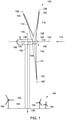
- FIG. 1 is a schematic view of an exemplary wind turbine 100.
- wind turbine 100 is a horizontal-axis wind turbine.
- wind turbine 100 may be a vertical-axis wind turbine.
- Wind turbine 100 includes a tower 102 extending from and coupled to a supporting surface 104.
- Tower 102 may be coupled to surface 104 with anchor bolts or via a foundation mounting piece (neither shown).
- a nacelle 106 is coupled to tower 102, and a main shaft assembly 108 is coupled to nacelle 106.
- Main shaft assembly 108 includes a rotatable hub 110 and a plurality of rotor blades 112 coupled to hub 110.
- main shaft assembly 108 includes three rotor blades 112.
- main shaft assembly 108 may have any suitable number of rotor blades 112 to enable wind turbine 100 to function as described herein.
- Tower 102 may have a suitable height and/or construction that enables wind turbine 100 to function as described herein.
- Rotor blades 112 are spaced about hub 110 to facilitate rotating main shaft assembly 108, thereby transferring kinetic energy from wind 114 into usable mechanical energy, and subsequently, electrical energy.
- Main shaft assembly 108 and nacelle 106 are rotated about tower 102 on a yaw axis 116 to control a perspective of rotor blades 112 with respect to a direction of wind 114.
- Rotor blades 112 are mated to hub 110 by coupling a rotor blade root portion 118 to hub 110 at a plurality of load transfer regions 120.
- Load transfer regions 120 each have a hub load transfer region and a rotor blade load transfer region (both not shown in FIG. 1 ). Loads induced to rotor blades 112 are transferred to hub 110 via load transfer regions 120.
- Each rotor blade 112 also includes a rotor blade tip portion 122.
- rotor blades 112 have a length of between approximately 30 meters (m) (99 feet (ft)) and approximately 120 m (394 ft).
- rotor blades 112 may have any suitable length that enables wind turbine 100 to function as described herein.
- rotor blades 112 may have a suitable length less than 30 m or greater than 120 m.
- a pitch angle (not shown) of rotor blades 112 may be changed by a pitch assembly (not shown in FIG. 1 ). More specifically, increasing a pitch angle of rotor blade 112 decreases an amount of rotor blade surface area 126 exposed to wind 114 and, conversely, decreasing a pitch angle of rotor blade 112 increases an amount of rotor blade surface area 126 exposed to wind 114.
- the pitch angles of rotor blades 112 are adjusted about a pitch axis 128 at each rotor blade 112. In the exemplary embodiment, the pitch angles of rotor blades 112 are controlled individually.
- wind turbine 100 includes a main gearbox 130 and a generator 132 within nacelle 106.
- main shaft assembly 108 includes a low-speed shaft 134 that extends into main gearbox 130 and a high-speed shaft 136 that extends to generator 132.
- a plurality of wind turbines 100 form a wind park 140. Each of the plurality of wind turbines 100 in wind park 140 is constructed similarly to one another, and each wind turbine 100 includes a generator 132 which generates power to be transmitted to the electrical utility grid.
- FIG. 2 is a schematic view of an exemplary electrical power system 200 for wind turbine 100 (shown in FIG. 1 ).
- electrical power system 200 converts the mechanical energy of rotor blades 112, low-speed shaft 134, gearbox 130, high-speed shaft 136, and generator 132 into electrical energy to transmit over grid bus 138 to the utility grid (not shown) through a transformer 202.
- Rotor blades 112 mechanically couple with gearbox 130 through low-speed shaft 134, and gearbox 130 mechanically couples with generator 132 through high-speed shaft 136.
- Electrical power system 200 further includes a controller 206 coupled in electronic data communication with power converter 204 to control the operation of power converter 204.
- controller 206 is a portion of a separate, stand-alone unit from power converter 204. In an alternative embodiment, controller 206 is integrated with power converter 204.
- generator 132 is a DFIG including a rotor 208, and a stator 210 magnetically coupled to rotor 208.
- high speed shaft 136 rotatingly drives rotor 208.
- a rotating magnetic field is induced within rotor 208 and a voltage is induced within stator 210.
- generator 132 converts the rotational mechanical energy to a sinusoidal, three-phase alternating current (AC) electrical energy signal in stator 210.
- the associated electrical power is transmitted to transformer 202 by a stator bus 212.
- Transformer 202 is configured to step up the voltage amplitude of the electrical power, and the subsequently transformed electrical power is further transmitted to an electrical utility grid (not shown) by grid bus 138.
- a second electrical power transmission path is provided. Electrical, three-phase, sinusoidal, AC power is generated within rotor 208 and is transmitted to power converter 204 by a rotor bus 214.
- Power converter 204 includes additional components, such as line contactors 216 that electrically couple to each of the individual power lines (not numbered) of rotor bus 214.
- Electrical power system 200 is further configured to measure rotor voltages in generator 132.
- the rotor voltages can be recorded in several ways.
- the rotor voltage measurements are obtained using signals acquired by line contactors 216, for example, and then communicated with controller 206 through electronic data communication from power converter 204, and then used for analysis.
- line contactors 216 contacting each of at least three power lines (not separately numbered) of rotor bus 214, and line contactors 216 thereby function as sensors configured to acquire data of the rotor voltage measurements and communicate this data, either by direct wiring or wireless transmission, to a processor (not shown) of power converter 204 or controller 206, which includes, without limitation, a general purpose central processing unit (CPU), a graphics processing unit (GPU), a microcontroller, a reduced instruction set computer (RISC) processor, an application specific integrated circuit (ASIC), a programmable logic circuit (PLC), a field programmable gate array (FPGA), a digital signal processing (DSP) device, and/or any other circuit or processor capable of executing the functions described herein.
- the processor is remotely located, and includes a receiver (not shown) capable of receiving voltage measurement data acquired by line contactors 216.
- a separate data acquisition system (DAQ) 218 is utilized to measure rotor voltages in generator 132.
- DAQ 218 is coupled directly to rotor bus 214 through a plurality of acquisition connectors 220, which transmit measured rotor voltages to DAQ 218, directly or by transmitters (not shown) capable of transmitting voltage data to respective receivers (not shown) within DAQ 218.
- DAQ 218 is configured to receive current measurement data from sensors 222, directly or by transmitters (not shown) capable of transmitting data to respective receivers (not shown) within DAQ 218.
- DAQ further includes an alert system 224 that is configured to process the measured rotor voltage data and transmit an alert to a display 226 based on the processed data, as discussed further below with respect to FIGs. 5-9 .
- the alert can be, without limitation, a warning light, a displayed numerical value, or a visual device that sufficiently represents a condition of rotor 208.
- the alert can be an audible alarm or notification.
- Display 226 can be disposed proximate the location of turbine 100 (shown in FIG. 1 ) itself, at a remote power station (not shown), and/or on a remote device (also not shown), such as a computer, laptop, tablet, or handheld device, programmed to receive and display processed voltage measurement data.
- fault detection system 228 includes acquisition connectors 220 and/or sensors 222, DAQ 218, and display 226.
- fault detection 228 is entirely contained within power converter 204 or controller 206.
- line contactors 216 perform the functions of acquisition connectors 220 and sensors 222
- the processor (not shown) of power converter 204 or controller 206 performs the data acquisition and processing functions of DAQ 218, and display 226 can be disposed locally or remotely, by direct or wireless coupling.
- FIG. 3 is an exemplary view of generator 132 as implemented with wind turbine 100 (shown in FIG. 1 ).
- generator 132 is a DFIG, and includes a wye-ring 300 and a plurality of end windings 302 that extend circumferentially around rotor 208 (shown in FIG. 2 ).
- Wye-ring 300 is disposed radially inside rotor 208 and couples to end windings 302.
- Wye-ring 300 is typically fabricated of one or more copper bars curved into a generally circular shape.
- Wye-ring 300 provides a floating, or ungrounded, neutral connection (not numbered and explained further below with respect to FIG. 5 ) for each of the phases of rotor windings.
- rotor 208 is a three-phase system. In an alternative embodiment, rotor 208 is a multi-phase system, configured for more than three electrical phases.
- generator 132 typically additionally includes a bearing shield and a generator rotor fan.
- FIG. 4 illustrates a schematic view of rotor 400.
- Rotor 400 includes a plurality of end windings 402 connected to a wye-ring 404 exhibiting an incipient two-crack condition. Except for the incipient two-crack condition, wye-ring 404 is the same as wye-ring 300 (shown in FIG. 3 ). Rotor 400 is therefore the same as rotor 208 (shown in FIG. 2 ), except for the incipient two-crack condition.
- Rotor 400 further includes connection lugs 406(a), 406(b), and 406(c). Connection lugs 406(a), 406(b), and 406(c) electrically connect wye-ring 404 to end windings 402.
- connection lugs 406 and wye-ring 404 are both made of copper, are brazed together to form a fixed mechanical connection.
- connection lugs 406 and wye-ring 404 are coupled together by a manufacturing process that enables operation of the DFIG, i.e., generator 132 (shown in FIG. 1 ), as described herein, including, without limitation, welding or casting a unitary fabrication.
- connection lugs 406 and wye-ring 404 experience strain induced thereon.
- thermal expansion and contraction may not be uniform between rotor end windings 402 and wye-ring 404, thereby leading to uneven expansion and contraction stresses to individual joints of wye-ring 404, as well as its curved ring portions (not numbered) between connection lugs 406.
- a first crack 408 may form in wye-ring 404 near connection lug 406(c).
- Rotor 400 will typically function with only a single crack.
- first crack 408 With only a single crack, i.e., first crack 408, current will flow through wye-ring 404 between connection lugs 406(b) and 406(a), and wye-ring 404 between connection lugs 406(b) and 406(c).
- first crack 408 proximate connection lug 406(c) imposes additional loads on connection lugs 406(a) and 406(b), and increase the stresses thereupon, and may accelerate development of a second crack 410.
- connection lug 406(b) Once second crack 410 fully develops proximate connection lug 406(b), an entire phase of rotor 400, i.e., at connection lug 406(a), is isolated from a floating neutral of rotor 400 (explained further below with respect to FIG. 5 ). Arcing between cracks can occur, and undesirably affect rotor insulation (not shown).
- first and second cracks 408, 410 in wye-ring 404 may occur anywhere along wye-ring 404 between connection lugs 406, and induce similar stresses thereon.
- second crack 410 is either incipient, i.e., only partially developed through wye-ring 404 prior to phase isolation from the floating neutral, or fully developed.
- the systems and methods described further below are capable of monitoring wye-ring 404 during operation such that incipient cracks can be detected and monitored before becoming fully developed cracks.
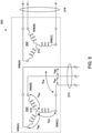
- FIG. 5 illustrates a schematic of an exemplary electrical system 500 of generator 132, FIGs. 2-3 .
- Electrical system 500 includes a rotor circuit 502, i.e., of rotor 208, FIG. 2 , and a stator circuit 504, i.e., of stator 210, FIG. 2 .
- Rotor circuit 502 includes a rotor phase 506(a), a rotor phase 506(b), and a rotor phase 506(c) that correspond to, that is, electrical magnetically coupled with, a stator phase 508(A), a stator phase 508(B), and a stator phase 508(C) of stator circuit 504, respectively.
- Rotor circuit 502 further includes a neutral point 510 corresponding to a neutral point 512 of stator circuit 504.
- Neutral point 510 is, in this example, a floating neutral.
- Rotor circuit 502 electrically couples to power converter 204, FIG. 2 , by rotor bus 214.
- stator circuit 504 electrically couples to transformer 202, FIG. 2 , by stator bus 212.
- electrical, three-phase, sinusoidal, AC power is generated within rotor circuit 502 and transmitted over rotor bus 214.
- voltage and current measurements can be taken at rotor phase 506(a), 506(b), and 506(c), e.g., by line contactors 216 (shown in FIG. 2 ). From these voltage and current measurements, symmetrical components of the zero sequence, the positive sequence, and the negative sequence are utilized to analyze the three-phase power system. These symmetrical components are generated by complex linear transformation of the measured voltage and current values, that is, the calculation allows conversion between the phase and symmetrical component domains, using methods including, without limitation, Laplace and Fourier transform algorithms.
- the respective negative sequence components of the complex voltage and current vectors are used for further analysis.
- Line-to-line voltages are convenient to obtain because it is typically convenient to take voltage measurements at rotor phases 506(a), 506(b), and 506(c) by accessing rotor bus 214 at line contactors 216, for example.
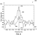
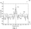
- FIGs. 6 and 7 illustrate graphical representations utilizing the complex voltage and current vectors, respectively, according to the calculations above, plotted against frequency.
- a Fast-Fourier transform FFT
- the results of the transformed vectors are discrete values which can be plotted against frequency, as discussed below.
- a voltage transform graph 600 includes a y-axis 602 (height direction) representing the transformed voltage vector magnitude, in units of decibels (dB), and an x-axis 604 (longitudinal dimension) representing frequency, in units of Hertz (Hz). Since an FFT is used to transform the complex voltage vector, the vertical scale of y-axis 604 represents relative power, which is best shown in dB. Voltage transform graph 600 superimposes a first voltage plot 606 with a second voltage plot 608, with both first and second voltage plots 606, 608 representing the distribution of discrete values of transformed complex voltage vectors against frequency.
- First plot 606 represents the distribution of transformed complex voltage vectors generated by measuring the phase voltages for wye-ring 404, exhibiting an incipient two-crack condition, as shown in FIG. 4 .
- Second voltage plot 608 comparably represents the distribution of discrete values of transformed complex voltage vectors for wye-ring 300, FIG. 3 , which has not developed an incipient two-crack condition, and therefore considered "healthy".
- the transformed complex voltage vector values are obtained for first plot 606 and second plot 608, these values are normalized over the spectrum to determine the fundamental operating frequency ⁇ 1 of the rotor voltage.
- the fundamental operating frequency ⁇ 1 is determined as the frequency at which the normalized values exhibit the largest magnitude component in the frequency spectrum.
- a negative fundamental frequency 610 is identified as being the negative of the fundamental operating frequency - ⁇ 1 .
- the normalized, transformed complex voltage vectors experience a peak magnitude, which is also known as the negative sequence component at the fundamental operating frequency.
- negative fundamental frequency 610 has a value of -16.5 Hz.
- the transformed complex voltage vectors will exhibit a positive sequence component at the fundamental operating frequency of 16.5 Hz.
- potential rotor imbalance is predicted by examining the negative sequence components. Specifically, a first peak magnitude 612 of first voltage plot 606 and a second peak magnitude 614 of second plot 608 substantially align at negative fundamental frequency 610. Peak magnitude 612, which corresponds to wye-ring 404 (shown in FIG. 4 ), having an incipient two-crack condition, is substantially larger than peak magnitude 614, which corresponds to healthy wye-ring 300 (shown in FIG. 3 ).
- a comparison of the phase-to-phase voltages can also indicate the probability of a developing, that is, incipient, two-crack condition, as shown in FIG. 4 .
- each of the phase-to-phase voltages V ab , V bc , and V ca is individually transformed into the frequency domain without having to calculate the complex voltage vector. Once transformed, the respective component that exhibits the lowest magnitude will indicate the two corresponding phases that have the healthiest section of wye-ring therebetween, e.g, portion of wye-ring 404 (shown in FIG.
- the frequency-transformed component of V ab has the lowest magnitude out of the three frequency-transformed phase-to-phase voltages, there is a greater probability that cracks have been forming in wye-ring 404 between rotor phases 506(a) and 506(c), and between rotor phases 506(b) and 506(c), than between rotor phases 506(a) and 506(b), as best seen in FIG. 5 .
- These frequency-transformed phase-to-phase voltage fundamental components may also indicate the relative health of individual sections, such as between connection lugs, of a single wye-ring with respect to its other sections.
- This alternative embodiment may also be utilized together with the calculation of the transformed complex voltage vector, described above.
- the transformed complex voltage vector is useful for comparing the relative overall condition of a wye-ring from one wind turbine in a wind park with that of another wye-ring from a different wind turbine in the same wind park.
- the phase-to-phase voltage comparisons are useful in assessing the condition of one phase of a particular wye-ring with other phases of the same wye-ring.
- useful indicators are obtained utilizing the root mean square (RMS) of the line-to-line voltages.
- RMS root mean square
- V ab when the RMS value of V ab has the lowest magnitude out of the three line-to-line voltages, there is a greater probability that cracks have been forming in wye-ring 404, (shown in FIG. 4 ), between rotor phases 506(a) and 506(c), and also between rotor phases 506(b) and 506(c), than between rotor phases 506(a) and 506(b), as best seen in FIG. 5 .
- this alternative embodiment may also be utilized together with calculations of the transformed complex voltage vector. Whereas the RMS values are indicative of the location of an imbalance between rotor phases 506, the RMS values, by themselves, are less indicative of quantified information, such as the magnitude of an imbalance formed by an incipient, developing crack.
- the complex rotor voltage vector is determined by measuring line-to-neutral (also known as "phase-to-neutral") voltages V an , V bn , and V cn rather than of the line-to-line measurements, described above.
- line-to-neutral also known as "phase-to-neutral”
- a current transform graph 700 includes a y-axis 702 (height direction) representing the transformed current vector magnitude, in units of dB, and an x-axis 704 (longitudinal dimension) representing frequency, in units of Hz. Similar to voltage transform graph 600, the results of the transformed complex current vector from the FFT are also shown in dB.
- Current transform graph 700 superimposes a first current plot 706 with a second current plot 708.
- First current plot 706 represents a distribution of discrete values of transformed complex current vectors (also in units of dB) against frequency (again in units of Hz), for wye-ring 404, exhibiting an incipient two-crack condition, as shown in FIG. 4 .
- Second current plot 708 comparably represents a distribution of discrete values of transformed complex current vectors against frequency for wye-ring 300 (shown in FIG. 3 ), which has not developed an incipient two-crack condition.
- first current plot 706 and second current plot 708 are also normalized to determine the fundamental operating frequency ⁇ 1 of the rotor current in the same manner that the fundamental operating frequency ⁇ 1 was determined for the rotor voltage, as discussed above.
- a negative fundamental frequency 710 of the rotor current is therefore also -16.5 Hz, as in the embodiment shown with respect to FIG. 6 .
- a first peak magnitude 712 of first current plot 706 and a second peak magnitude 714 of second current plot 708 substantially align at negative fundamental frequency 710. Comparing voltage transform graph 600 with current transform graph 700, it can be seen that negative fundamental frequency 610 is consistent with negative fundamental frequency 710 weather measuring voltage or current. Looking at FIG. 7 in particular, graph 700 illustrates that peak magnitude 712, corresponding to an incipient two-crack condition, is substantially similar to peak magnitude 714, which corresponds to an operational wye-ring.
- FIG. 6 illustrates a distinct advantage of the present embodiments over conventional systems that measure only rotor currents.
- a DFIG e.g., generator 132, FIG. 2
- the DFIG controller e.g., controller 206 (shown in FIG. 2 ).
- rotor currents at the fundamental operating frequency are regulated to form a substantially balanced three-phase system even in the presence of a physical asymmetry in the rotor.
- a detected imbalance from the measured voltages is indicative of an operational physical asymmetry of the wye-ring, such as from an incipient or fully developed first crack, or from a developing two-crack condition.
- bar graph 800 includes a vertical axis 802 representing the magnitude of a fault indicator based on measured voltages, and a horizontal axis 804 representing which of a plurality of individual wind turbines (e.g. wind park 140, FIG. 1 ), WT1, WT2, etc., is measured.
- bar graph 800 represents visual data depicted on a physical display screen (e.g., display 226, FIG.
- First voltage fault indicator 806 indicates the physical asymmetry of a wind turbine generator WT1 having a wye-ring, e.g., wye-ring 404 (shown in FIG. 4 ), exhibiting an incipient two-crack condition.
- Second voltage fault indicator 808 indicates the relative physical asymmetry of a wind turbine generator WT2 a wye-ring, e.g., wye-ring 300 (shown in FIG. 3 ), without an incipient two-crack condition.
- a comparison of first voltage fault indicator 806 with second voltage fault indicator 808 indicates that an incipient two-crack condition is present for wye-ring 404, and not present for wye-ring 300.
- First and second voltage fault indicators 806, 808 relate in magnitude to respective normalized values of peak magnitudes 612, 614, as shown in FIG. 6 , which are the identified negative sequence components of the transformed voltages. That is, the respective values of fault indicator 806, 808 are assigned based at least in part on the Fourier transform of the voltages measured at each phase of the wye-ring, e.g. wye-ring 300, FIG. 3 , wye-ring 404, FIG. 4 .
- the negative sequence components of the transformed complex rotor voltage vectors (shown in FIG. 6 ) are first normalized, and thereby converted into discrete numerical fault indicator values (shown in FIG.
- the "zero" value on vertical axis 802 can be set by an arbitrary offset number for illustrative purposes. In an exemplary embodiment, the zero value of vertical axis 802 is set to a baseline value of a new rotor and wye-ring measured at first operation.
- a DFIG controller e.g., controller 206 (shown in FIG. 2 ) is programmed to monitor rotor voltages, e.g., from line contactors 216, and calculate complex voltage and current vectors, negative sequence components, and discrete fault indicators, as described above, according to an exemplary embodiment.
- a separate data acquisition circuit e.g. DAQ 218 (shown in FIG. 2 ) is programmed to monitor the same rotor voltages e.g., from acquisition connectors 220, and perform the same calculations.
- similar calculations can be performed by separate or integrated devices, including, without limitation, a general purpose central processing unit (CPU), a graphics processing unit (GPU), a microcontroller, a reduced instruction set computer (RISC) processor, an application specific integrated circuit (ASIC), a programmable logic circuit (PLC), and/or any other circuit or processor capable of executing the functions described herein that are capable of receiving data acquired by sensors electrically coupled to rotor phases, e.g., rotor phases 506 (shown in FIG. 5 ), or to a rotor bus, e.g., rotor bus 214 (shown in FIG. 2 ).
- CPU central processing unit
- GPU graphics processing unit
- microcontroller a reduced instruction set computer
- RISC reduced instruction set computer
- ASIC application specific integrated circuit
- PLC programmable logic circuit
- any other circuit or processor capable of executing the functions described herein that are capable of receiving data acquired by sensors electrically coupled to rotor phases, e.g., rotor phases 50
- the fault indicators can be transmitted and displayed as an alert at the location of the turbine itself, at a remote power station, and/or on a remote device, such as a computer, laptop, tablet, or handheld device, programmed to receive and display fault indicator data.
- the alert is an alarm triggered at the respective display device, e.g., display 226 (shown in FIG. 2 ) when a fault indicator exceeds a threshold value.
- the alert can be, without limitation, a warning light, a displayed numerical value, or a visual device that sufficiently displays the relative magnitude of the respective fault indicator.
- the alert can be an audible alarm or notification.
- the alert system e.g., alert system 224 (shown in FIG. 2 ) is configured to display, i.e., on display 226 (shown in FIG. 2 ) the respective fault indicators for individual turbines 100 in sequential order, according to the magnitude of the individual fault indicators.
- Individual turbines 100 displaying the highest magnitude fault indicators will be considered to be those having the highest probability of wye-ring damage, and thus those most in need of service, as compared with others of the plurality of wind turbines.
- a change in the magnitude of a particular fault indicator is monitored with respect to time, and a significant increase in the magnitude of the monitored fault indicator over a short period of time will indicate a high probability of a crack developing in the respective wye-ring.
- bar graph 900 includes a vertical axis 902 representing the magnitude of an impedance fault indicator (FIi), and a horizontal axis 904 representing which of a plurality of individual wind turbines, e.g., WT1, WT2, etc., is represented.
- bar graph 900 represents visual data depicted on a physical display screen (not shown) of a first impedance fault indicator 906 and a second impedance fault indicator 908.
- First impedance fault indicator 906 indicates the asymmetry of a wind turbine generator WT1 having a wye-ring, e.g., wye-ring 404 (shown in FIG. 4 ), exhibiting an incipient two-crack condition.
- Second impedance fault indicator 908 indicates the asymmetry of a wind turbine generator WT2 a wye-ring, e.g., wye-ring 300 (shown in FIG. 3 ), without an incipient two-crack condition.
- a wye-ring e.g., wye-ring 300 (shown in FIG. 3 )
- this presumption is not always correct. Nevertheless, current measurements from a DFIG can yield useful information as a supplement to the voltage calculations described above.
- the ratio of the rotor's negative sequence voltage, e.g., peak magnitudes 612, 614 (shown in FIG. 6 ), and the rotor's negative sequence current, e.g., peak magnitudes 712, 714 (shown in FIG. 7 ), respectively, at negative fundamental frequency 610, 710 is calculated to determine respective negative sequence impedance values, the magnitudes of which are used to determine first impedance fault indicator 906 and second impedance fault indicator 908, respectively.
- a larger numerical value for a impedance fault indicator FI I will also indicate a greater probability that the wye-ring exhibits an asymmetry in the rotor circuit that stems from a defective wye-ring, such as an incipient two-crack condition.
- FIG. 10 is a flow chart diagram of a process 1000 for determining fault indicators 806, 808, shown in FIG. 8 , and 906, 908, shown in FIG. 9 , from electrical power system 200, shown in FIG. 2 .
- Process 1000 begins at step 1002.
- electric power is generated by DFIG 132, shown in FIG. 1 .
- DFIG 132 is operational, process 1000 proceeds to step 1004.
- Step 1004 is a data collection step.
- controller 206 or DAQ 218 measures the rotor voltages for each phase, i.e., phase-to-phase, phase-to-neutral, etc., of the particular wye-ring being monitored, e.g., wye-ring 300, shown in FIG. 3 , or wye-ring 404, shown in FIG. 4 , and then proceeds to step 1006.
- Step 1006 is a calculation step.
- process 1000 calculates the complex voltage vector V r (see Eq. 1, above), and then proceeds to step 1008, which is another calculation step.
- process 1000 performs an FFT on the calculated complex voltage vector V r to convert the measured data into the frequency domain.
- step 1010 the fundamental rotor operating frequency ⁇ i is determined.
- the fundamental rotor operating frequency ⁇ i can be determined by identifying the frequency at which the peak magnitude of the transformed complex voltage vector V r occurs.
- step 1012 the entire measured frequency spectrum was normalized to the fundamental operating frequency ⁇ i to cancel out units of voltage, and thus be able to analyze the measured and converted data values simply as logarithmic magnitudes.
- step 1014 the this negative sequence component at the fundamental operating frequency of normalized rotor voltage is identified. This step is also referred to as determining the peak magnitude, e.g. peak magnitude 612 or 614, of the normalized, transformed complex voltage vector V r at negative fundamental frequency 610.
- the negative sequence component identified in step 1014 can be directly implemented as the voltage fault indicator FIv, and thus process 1000 can skip step 1016, and proceed directly to step 1018, where the voltage fault indicator FIv is directly displayed, e.g., on display 226, shown in FIG. 2 , as a discrete quantifiable value.
- process 1000 instead proceeds from step 1014 to optional step 1016, where a baseline offset value is added to the logarithmic negative sequence component identified in step 1014.
- the baseline offset value can be determined by running process 1000 against a brand-new turbine and rotor are known to be healthy.
- the baseline offset value can be set according to the initial operation and measurement of the turbine and DFIG now being measured for comparison purposes. Once the baseline offset value is added to the normalized logarithmic negative sequence component, process 1000 will proceed to final step 1018, where the offset value of the negative sequence component is displayed against its baseline value.
- optional sub-process 1020 runs simultaneously main process 1000, and provides supplemental measurements and data information. Referring back to step 1004, process 1000 proceeds to optional step 1022, in addition to step 1006.
- Optional step 1022 is a calculation step. In step 1022, the RMS values are calculated from the voltages measured in step 1004, and then process 1000 proceeds to step 1024.
- Step 1024 is also a calculation step. In step 1024, the respective RMS values for each phase are calculated, as described above, and then combined with the offset value of the negative sequence component determined in step 1016.
- step 1016 where the offset value determined in step 1016 is indicative of an incipient one-crack or two-crack asymmetry developing in the wye-ring, e.g., wye-ring 404, this data from step 1016 is combined with the data from step 1024 to determine the location of the problem location of the detected asymmetry.
- Process 1000 then proceeds to step 1026, where the combined information from step 1024 can be displayed as the probable location of an asymmetry reflected by the display of the voltage fault indicator FIv.
- a repair crew for example, can significantly expedite the repair process of a deteriorating wye-ring, thereby saving both time and financial resources.
- optional sub-process 1028 also, or alternatively, runs simultaneously main process 1000, and provides further supplemental measurements and data information.
- process 1000 proceeds to optional step 1030, in addition to step 1004.
- Optional step 1030 is a calculation step very similar to calculation step 1004.
- controller 206 or DAQ 218 measures the rotor currents for each phase.
- steps 1030 through 1040 of optional sub-process 1028 are nearly identical to mandatory steps 1004 through 1014, except that each of these steps from optional sub-process 1028 performs the same calculations as its mandatory counterpart except only on current data, as opposed to voltage data.
- optional sub-process 1028 proceeds, in order, to measure rotor currents in step 1030, calculate complex current vector in step 1032 from the measured rotor currents, perform an FFT on the complex current vector I r in step 1034, determine the rotor fundamental operating frequency ⁇ i in step 1036, normalize the measured current vector values over the frequency spectrum to eliminate units of current in step 1038, and find the negative sequence component at the fundamental operating frequency of the normalized rotor current in step 1040.
- Step 1042 is a calculation step, where the negative sequence impedance is calculated.
- the negative sequence impedance is calculated as a ratio of the negative sequence components of the normalized rotor voltage and the normalized rotor current at the fundamental operating frequency ⁇ i .
- the negative sequence impedance is calculated by simply subtracting respective negative sequence components of the normalized rotor current, in dB, from the normalized rotor voltage, also in dB, since the volts and amps units drop out from the normalization process.
- process 1000 proceeds to step 1044, where the impedance fault indicator FIz is displayed.
- this additional fault indicator can be useful to determine if, for example, controller 26 is not adequately maintaining the DFIG current within the expected narrow operating parameters.
- negative sequence components are calculated at negative fundamental frequencies.
- similar analyses can be performed utilizing other frequencies that are excited through the operation of the DFIG, depending on the bandwidth of the controller used with the DFIG.
- a sufficient controller bandwidth allows the converter, e.g. power converter 204 (shown in FIG. 2 ) to utilize its switching frequency to calculate the complex voltage and current vectors.
- a higher controller sampling frequency is implemented. Higher bandwidth and sampling frequencies can be obtained by the addition of a data acquisition system (e.g., optional DAQ 218, shown in FIG. 2 ).
- the analysis of the fundamental rotor voltage in this alternative embodiment can also be conducted utilizing command signals generated by software installed on the controller, a separate data acquisition system, or a computing device capable of receiving relevant voltage and current sensor measurements.
- the voltage and current measurements are obtained from normal operational signals, and while the wind turbine and its generator are fully online and operationally producing electrical power for the utility grid.
- Present systems and methods are not able to diagnose a developing fault in the wye-ring of the rotor without having to first take the wind turbine off-line and out of service (typically requiring dismantling of the generator), and then without having to inject a separate diagnostic signal into the system (requiring additional hardware), as is conventionally known.
- the conventional wye-ring diagnosis methods are not performed while the DFIG is generating power to the utility grid.
- the systems and methods described herein allow for the early identification of a defect of the wye-ring of a DFIG's rotor at an incipient stage. Through such identification, an early warning can be sent of potential damage to the wye-ring, which can be utilized to prevent an otherwise unexpected open circuit condition in the rotor circuit of the generator. Such early intervention reduces repair costs to the generator, and also avoids extended outage of the wind turbine and increased maintenance and repair costs.
- the early warning advantages of the present embodiments advantageously enable a repair/maintenance crew to prioritize wye-ring crack repairs of individual turbines in a desired order, according to which respective rotors exhibit fault indicators having the greatest magnitude.
- Exemplary embodiments of wye-ring crack detection in a wind turbine generator and an electric power generation facility, and a system and methods for detecting the same, are described above in detail.
- the methods, facilities, systems, and apparatus are not limited to the specific embodiments described herein, but rather, components of the facilities, systems, and apparatus, and/or steps of the methods may be utilized independently and separately from other components and/or steps described herein.
- the exemplary system and methods may also be used in combination with other power conversion apparatus and methods utilizing a DFIG, and are not limited to practice with only the electric power systems as described herein. Rather, the exemplary embodiment can be implemented and utilized in connection with many other DFIG electric power conversion applications.
- the above-described integrated sensors and associated sensing systems facilitate extended operation in harsh environments. Specifically, integrating a significant portion of sensing system components in high-temperature and rotatable components during the manufacture of such components reduces the amount of time and resources expended in preparing the high-temperature and rotatable components for insertion into the respective turbomachine after they are manufactured. Further, specifically, the integrated sensors and associated sensing systems described herein include substrate materials and dielectric materials integrated as part of the sensors such that the sensors may be positioned on components, or portions of component, that do not have sufficient substrate and dielectric materials to accept known sensors.
- Such integration of the sensors with the components includes adding the necessary substrate and/or dielectric materials to the sensors as sensing device features to facilitate placement of the sensors in regions that would otherwise frustrate use of such sensors thereon. Therefore, such integration of the sensors and components facilitates placing the sensors at the most appropriate and desired positions on the components. Further, such integration of the sensors and high-temperature and rotatable components will increase the hurdles to non-OEM (original equipment manufacturer) entities for attempted duplication.
- OEM original equipment manufacturer
- An exemplary technical effect of the systems and apparatus described herein includes at least one of: (a) integrating sensing system devices in components during the manufacture of such components, thereby reducing the amount of time and resources expended in preparing the components for insertion into the respective turbomachines after they are manufactured; (b) facilitating placement of the sensor components at the most appropriate and desired positions on the high-temperature and rotatable components; (c) positioning sensors in harsh environments that do not have delicate chip features, thereby facilitating more robust sensing devices; (d) providing sensors that embedded within the associated components during manufacture and are not affixed to their associated components subsequent to manufacturing of those components, thereby facilitating sturdier sensing devices; and (e) facilitating passive operation of a machine sensor in a wireless environment.
- Some embodiments involve the use of one or more electronic or computing devices.
- Such devices typically include a processor or controller, such as a general purpose central processing unit (CPU), a graphics processing unit (GPU), a microcontroller, a reduced instruction set computer (RISC) processor, an application specific integrated circuit (ASIC), a programmable logic circuit (PLC), a field programmable gate array (FPGA), a digital signal processing (DSP) device, and/or any other circuit or processor capable of executing the functions described herein.
- the methods described herein may be encoded as executable instructions embodied in a computer readable medium, including, without limitation, a storage device and/or a memory device. Such instructions, when executed by a processor, cause the processor to perform at least a portion of the methods described herein.
- the above examples are exemplary only, and thus are not intended to limit any way the definition and/or meaning of the term processor.
Landscapes
- Engineering & Computer Science (AREA)
- Power Engineering (AREA)
- Life Sciences & Earth Sciences (AREA)
- Sustainable Energy (AREA)
- Sustainable Development (AREA)
- Microelectronics & Electronic Packaging (AREA)
- Chemical & Material Sciences (AREA)
- Combustion & Propulsion (AREA)
- Mechanical Engineering (AREA)
- General Engineering & Computer Science (AREA)
- Control Of Eletrric Generators (AREA)
- Wind Motors (AREA)
Priority Applications (3)
| Application Number | Priority Date | Filing Date | Title |
|---|---|---|---|
| EP16206411.7A EP3339638B1 (en) | 2016-12-22 | 2016-12-22 | Systems for crack detection in doubly-fed induction generators |
| ES16206411T ES2911876T3 (es) | 2016-12-22 | 2016-12-22 | Sistemas para la detección de grietas en generadores de inducción doblemente alimentados |
| DK16206411.7T DK3339638T3 (da) | 2016-12-22 | 2016-12-22 | Systemer til revnedetektion i dobbeltforsynede induktionsgeneratorer |
Applications Claiming Priority (1)
| Application Number | Priority Date | Filing Date | Title |
|---|---|---|---|
| EP16206411.7A EP3339638B1 (en) | 2016-12-22 | 2016-12-22 | Systems for crack detection in doubly-fed induction generators |
Publications (2)
| Publication Number | Publication Date |
|---|---|
| EP3339638A1 EP3339638A1 (en) | 2018-06-27 |
| EP3339638B1 true EP3339638B1 (en) | 2022-01-26 |
Family
ID=57749724
Family Applications (1)
| Application Number | Title | Priority Date | Filing Date |
|---|---|---|---|
| EP16206411.7A Active EP3339638B1 (en) | 2016-12-22 | 2016-12-22 | Systems for crack detection in doubly-fed induction generators |
Country Status (3)
| Country | Link |
|---|---|
| EP (1) | EP3339638B1 (da) |
| DK (1) | DK3339638T3 (da) |
| ES (1) | ES2911876T3 (da) |
Families Citing this family (4)
| Publication number | Priority date | Publication date | Assignee | Title |
|---|---|---|---|---|
| CN109444737B (zh) * | 2018-09-11 | 2021-01-05 | 昆明理工大学 | 一种计及撬棒保护动作时间的双馈风机三相短路电流的解析方法 |
| CN110649846B (zh) * | 2019-09-29 | 2021-06-15 | 湖南科技大学 | 基于滑模观测器的双馈感应发电机故障检测方法 |
| CN112232414B (zh) * | 2020-10-16 | 2021-06-15 | 广东石油化工学院 | 一种基于x,y双测点频谱数据的三重并发故障分析方法 |
| US11486355B2 (en) * | 2020-12-31 | 2022-11-01 | General Electric Company | Method for operating doubly-fed wind turbine generator as a virtual synchronous machine to provide grid-forming control thereof |
Family Cites Families (3)
| Publication number | Priority date | Publication date | Assignee | Title |
|---|---|---|---|---|
| US5514978A (en) * | 1995-03-20 | 1996-05-07 | General Electric Company | Stator turn fault detector for AC motor |
| US10359473B2 (en) * | 2012-05-29 | 2019-07-23 | Nutech Ventures | Detecting faults in turbine generators |
| US9411017B2 (en) * | 2013-11-26 | 2016-08-09 | General Electric Company | Method for inspecting wye ring |
-
2016
- 2016-12-22 DK DK16206411.7T patent/DK3339638T3/da active
- 2016-12-22 ES ES16206411T patent/ES2911876T3/es active Active
- 2016-12-22 EP EP16206411.7A patent/EP3339638B1/en active Active
Also Published As
| Publication number | Publication date |
|---|---|
| ES2911876T3 (es) | 2022-05-23 |
| EP3339638A1 (en) | 2018-06-27 |
| DK3339638T3 (da) | 2022-05-02 |
Similar Documents
| Publication | Publication Date | Title |
|---|---|---|
| US10184985B2 (en) | Systems and methods for crack detection in doubly-fed induction generators | |
| JP5733913B2 (ja) | 回転機械系の異常診断方法 | |
| EP3480610B1 (en) | Diagnosing a winding set of a stator | |
| EP3339638B1 (en) | Systems for crack detection in doubly-fed induction generators | |
| EP2565658B1 (en) | Fault detection based on current signature analysis for a generator | |
| US10273940B2 (en) | System and method for detecting pitch bearing damage in a wind turbine | |
| Thomson et al. | Motor Current Signature Analysis To Detect Faults In Induction Motor Drives-Fundamentals, Data Interpretation, And Industrial Case Histories. | |
| EP3797304B1 (en) | System and method for monitoring an operating condition of an electrical device when in operation | |
| EP3068040A1 (en) | Fault detection and diagnosis in an induction motor | |
| JP6017649B2 (ja) | 回転機械系の異常診断方法 | |
| Antonino-Daviu et al. | Reliable detection of rotor winding asymmetries in wound rotor induction motors via integral current analysis | |
| KR100608235B1 (ko) | 유도전동기의 실시간 수명 예측, 결함 감지 방법 및 장치 | |
| EP2728367B1 (en) | A method for detecting a fault condition in an electrical machine | |
| CN109297716B (zh) | 一种双馈型风力发电机振动故障诊断方法 | |
| WO2019082277A1 (ja) | 異常診断装置、異常診断方法及び異常診断システム | |
| EP2878813B1 (en) | Method for inspecting wye ring | |
| KR101140613B1 (ko) | 전동기의 온-사이트 결함 진단 방법 | |
| JP5828948B2 (ja) | 回転機械系の異常診断方法 | |
| EP3879282A1 (en) | Early detection of insulation failure for electric generators | |
| RU90199U1 (ru) | Устройство диагностики электродвигателей переменного тока и связанного с ними механического оборудования | |
| da Silva Gazzana et al. | An automated system for incipient fault detection and diagnosis in induction motors based on MCSA | |
| JP2021028591A (ja) | 回転電機の診断システム及び診断方法 | |
| Treml et al. | Broken rotor bar fault detection in asynchronous machines using vibration analysis | |
| Gazzana et al. | A system for incipient fault detection and fault diagnosis based on MCSA | |
| Hajiabady | Integrated condition monitoring of industrial wind turbines |
Legal Events
| Date | Code | Title | Description |
|---|---|---|---|
| PUAI | Public reference made under article 153(3) epc to a published international application that has entered the european phase |
Free format text: ORIGINAL CODE: 0009012 |
|
| STAA | Information on the status of an ep patent application or granted ep patent |
Free format text: STATUS: THE APPLICATION HAS BEEN PUBLISHED |
|
| AK | Designated contracting states |
Kind code of ref document: A1 Designated state(s): AL AT BE BG CH CY CZ DE DK EE ES FI FR GB GR HR HU IE IS IT LI LT LU LV MC MK MT NL NO PL PT RO RS SE SI SK SM TR |
|
| AX | Request for extension of the european patent |
Extension state: BA ME |
|
| STAA | Information on the status of an ep patent application or granted ep patent |
Free format text: STATUS: REQUEST FOR EXAMINATION WAS MADE |
|
| 17P | Request for examination filed |
Effective date: 20190102 |
|
| RBV | Designated contracting states (corrected) |
Designated state(s): AL AT BE BG CH CY CZ DE DK EE ES FI FR GB GR HR HU IE IS IT LI LT LU LV MC MK MT NL NO PL PT RO RS SE SI SK SM TR |
|
| STAA | Information on the status of an ep patent application or granted ep patent |
Free format text: STATUS: REQUEST FOR EXAMINATION WAS MADE |
|
| REG | Reference to a national code |
Ref country code: DE Ref legal event code: R079 Ref document number: 602016068622 Country of ref document: DE Free format text: PREVIOUS MAIN CLASS: F03D0017000000 Ipc: H02P0009000000 |
|
| GRAP | Despatch of communication of intention to grant a patent |
Free format text: ORIGINAL CODE: EPIDOSNIGR1 |
|
| STAA | Information on the status of an ep patent application or granted ep patent |
Free format text: STATUS: GRANT OF PATENT IS INTENDED |
|
| RIC1 | Information provided on ipc code assigned before grant |
Ipc: H02K 11/26 20160101ALI20210212BHEP Ipc: H02P 9/00 20060101AFI20210212BHEP Ipc: H02K 7/18 20060101ALI20210212BHEP Ipc: F03D 17/00 20160101ALI20210212BHEP Ipc: H02K 3/51 20060101ALI20210212BHEP |
|
| INTG | Intention to grant announced |
Effective date: 20210303 |
|
| GRAJ | Information related to disapproval of communication of intention to grant by the applicant or resumption of examination proceedings by the epo deleted |
Free format text: ORIGINAL CODE: EPIDOSDIGR1 |
|
| STAA | Information on the status of an ep patent application or granted ep patent |
Free format text: STATUS: REQUEST FOR EXAMINATION WAS MADE |
|
| INTC | Intention to grant announced (deleted) | ||
| GRAP | Despatch of communication of intention to grant a patent |
Free format text: ORIGINAL CODE: EPIDOSNIGR1 |
|
| STAA | Information on the status of an ep patent application or granted ep patent |
Free format text: STATUS: GRANT OF PATENT IS INTENDED |
|
| INTG | Intention to grant announced |
Effective date: 20210819 |
|
| GRAS | Grant fee paid |
Free format text: ORIGINAL CODE: EPIDOSNIGR3 |
|
| STAA | Information on the status of an ep patent application or granted ep patent |
Free format text: STATUS: GRANT OF PATENT IS INTENDED |
|
| GRAA | (expected) grant |
Free format text: ORIGINAL CODE: 0009210 |
|
| STAA | Information on the status of an ep patent application or granted ep patent |
Free format text: STATUS: THE PATENT HAS BEEN GRANTED |
|
| AK | Designated contracting states |
Kind code of ref document: B1 Designated state(s): AL AT BE BG CH CY CZ DE DK EE ES FI FR GB GR HR HU IE IS IT LI LT LU LV MC MK MT NL NO PL PT RO RS SE SI SK SM TR |
|
| REG | Reference to a national code |
Ref country code: GB Ref legal event code: FG4D |
|
| REG | Reference to a national code |
Ref country code: CH Ref legal event code: EP |
|
| REG | Reference to a national code |
Ref country code: AT Ref legal event code: REF Ref document number: 1466061 Country of ref document: AT Kind code of ref document: T Effective date: 20220215 |
|
| REG | Reference to a national code |
Ref country code: IE Ref legal event code: FG4D |
|
| REG | Reference to a national code |
Ref country code: DE Ref legal event code: R096 Ref document number: 602016068622 Country of ref document: DE |
|
| REG | Reference to a national code |
Ref country code: DK Ref legal event code: T3 Effective date: 20220428 |
|
| REG | Reference to a national code |
Ref country code: ES Ref legal event code: FG2A Ref document number: 2911876 Country of ref document: ES Kind code of ref document: T3 Effective date: 20220523 |
|
| REG | Reference to a national code |
Ref country code: LT Ref legal event code: MG9D |
|
| REG | Reference to a national code |
Ref country code: NL Ref legal event code: MP Effective date: 20220126 |
|
| REG | Reference to a national code |
Ref country code: AT Ref legal event code: MK05 Ref document number: 1466061 Country of ref document: AT Kind code of ref document: T Effective date: 20220126 |
|
| PG25 | Lapsed in a contracting state [announced via postgrant information from national office to epo] |
Ref country code: NL Free format text: LAPSE BECAUSE OF FAILURE TO SUBMIT A TRANSLATION OF THE DESCRIPTION OR TO PAY THE FEE WITHIN THE PRESCRIBED TIME-LIMIT Effective date: 20220126 |
|
| PG25 | Lapsed in a contracting state [announced via postgrant information from national office to epo] |
Ref country code: SE Free format text: LAPSE BECAUSE OF FAILURE TO SUBMIT A TRANSLATION OF THE DESCRIPTION OR TO PAY THE FEE WITHIN THE PRESCRIBED TIME-LIMIT Effective date: 20220126 Ref country code: RS Free format text: LAPSE BECAUSE OF FAILURE TO SUBMIT A TRANSLATION OF THE DESCRIPTION OR TO PAY THE FEE WITHIN THE PRESCRIBED TIME-LIMIT Effective date: 20220126 Ref country code: PT Free format text: LAPSE BECAUSE OF FAILURE TO SUBMIT A TRANSLATION OF THE DESCRIPTION OR TO PAY THE FEE WITHIN THE PRESCRIBED TIME-LIMIT Effective date: 20220526 Ref country code: NO Free format text: LAPSE BECAUSE OF FAILURE TO SUBMIT A TRANSLATION OF THE DESCRIPTION OR TO PAY THE FEE WITHIN THE PRESCRIBED TIME-LIMIT Effective date: 20220426 Ref country code: LT Free format text: LAPSE BECAUSE OF FAILURE TO SUBMIT A TRANSLATION OF THE DESCRIPTION OR TO PAY THE FEE WITHIN THE PRESCRIBED TIME-LIMIT Effective date: 20220126 Ref country code: HR Free format text: LAPSE BECAUSE OF FAILURE TO SUBMIT A TRANSLATION OF THE DESCRIPTION OR TO PAY THE FEE WITHIN THE PRESCRIBED TIME-LIMIT Effective date: 20220126 Ref country code: BG Free format text: LAPSE BECAUSE OF FAILURE TO SUBMIT A TRANSLATION OF THE DESCRIPTION OR TO PAY THE FEE WITHIN THE PRESCRIBED TIME-LIMIT Effective date: 20220426 |
|
| PG25 | Lapsed in a contracting state [announced via postgrant information from national office to epo] |
Ref country code: PL Free format text: LAPSE BECAUSE OF FAILURE TO SUBMIT A TRANSLATION OF THE DESCRIPTION OR TO PAY THE FEE WITHIN THE PRESCRIBED TIME-LIMIT Effective date: 20220126 Ref country code: LV Free format text: LAPSE BECAUSE OF FAILURE TO SUBMIT A TRANSLATION OF THE DESCRIPTION OR TO PAY THE FEE WITHIN THE PRESCRIBED TIME-LIMIT Effective date: 20220126 Ref country code: GR Free format text: LAPSE BECAUSE OF FAILURE TO SUBMIT A TRANSLATION OF THE DESCRIPTION OR TO PAY THE FEE WITHIN THE PRESCRIBED TIME-LIMIT Effective date: 20220427 Ref country code: FI Free format text: LAPSE BECAUSE OF FAILURE TO SUBMIT A TRANSLATION OF THE DESCRIPTION OR TO PAY THE FEE WITHIN THE PRESCRIBED TIME-LIMIT Effective date: 20220126 Ref country code: AT Free format text: LAPSE BECAUSE OF FAILURE TO SUBMIT A TRANSLATION OF THE DESCRIPTION OR TO PAY THE FEE WITHIN THE PRESCRIBED TIME-LIMIT Effective date: 20220126 |
|
| PG25 | Lapsed in a contracting state [announced via postgrant information from national office to epo] |
Ref country code: IS Free format text: LAPSE BECAUSE OF FAILURE TO SUBMIT A TRANSLATION OF THE DESCRIPTION OR TO PAY THE FEE WITHIN THE PRESCRIBED TIME-LIMIT Effective date: 20220526 |
|
| REG | Reference to a national code |
Ref country code: DE Ref legal event code: R097 Ref document number: 602016068622 Country of ref document: DE |
|
| PG25 | Lapsed in a contracting state [announced via postgrant information from national office to epo] |
Ref country code: SM Free format text: LAPSE BECAUSE OF FAILURE TO SUBMIT A TRANSLATION OF THE DESCRIPTION OR TO PAY THE FEE WITHIN THE PRESCRIBED TIME-LIMIT Effective date: 20220126 Ref country code: SK Free format text: LAPSE BECAUSE OF FAILURE TO SUBMIT A TRANSLATION OF THE DESCRIPTION OR TO PAY THE FEE WITHIN THE PRESCRIBED TIME-LIMIT Effective date: 20220126 Ref country code: RO Free format text: LAPSE BECAUSE OF FAILURE TO SUBMIT A TRANSLATION OF THE DESCRIPTION OR TO PAY THE FEE WITHIN THE PRESCRIBED TIME-LIMIT Effective date: 20220126 Ref country code: EE Free format text: LAPSE BECAUSE OF FAILURE TO SUBMIT A TRANSLATION OF THE DESCRIPTION OR TO PAY THE FEE WITHIN THE PRESCRIBED TIME-LIMIT Effective date: 20220126 Ref country code: CZ Free format text: LAPSE BECAUSE OF FAILURE TO SUBMIT A TRANSLATION OF THE DESCRIPTION OR TO PAY THE FEE WITHIN THE PRESCRIBED TIME-LIMIT Effective date: 20220126 |
|
| PG25 | Lapsed in a contracting state [announced via postgrant information from national office to epo] |
Ref country code: AL Free format text: LAPSE BECAUSE OF FAILURE TO SUBMIT A TRANSLATION OF THE DESCRIPTION OR TO PAY THE FEE WITHIN THE PRESCRIBED TIME-LIMIT Effective date: 20220126 |
|
| PLBE | No opposition filed within time limit |
Free format text: ORIGINAL CODE: 0009261 |
|
| STAA | Information on the status of an ep patent application or granted ep patent |
Free format text: STATUS: NO OPPOSITION FILED WITHIN TIME LIMIT |
|
| 26N | No opposition filed |
Effective date: 20221027 |
|
| PG25 | Lapsed in a contracting state [announced via postgrant information from national office to epo] |
Ref country code: SI Free format text: LAPSE BECAUSE OF FAILURE TO SUBMIT A TRANSLATION OF THE DESCRIPTION OR TO PAY THE FEE WITHIN THE PRESCRIBED TIME-LIMIT Effective date: 20220126 |
|
| PGFP | Annual fee paid to national office [announced via postgrant information from national office to epo] |
Ref country code: ES Payment date: 20230102 Year of fee payment: 7 |
|
| P01 | Opt-out of the competence of the unified patent court (upc) registered |
Effective date: 20230530 |
|
| PG25 | Lapsed in a contracting state [announced via postgrant information from national office to epo] |
Ref country code: IT Free format text: LAPSE BECAUSE OF FAILURE TO SUBMIT A TRANSLATION OF THE DESCRIPTION OR TO PAY THE FEE WITHIN THE PRESCRIBED TIME-LIMIT Effective date: 20220126 |
|
| REG | Reference to a national code |
Ref country code: CH Ref legal event code: PL |
|
| GBPC | Gb: european patent ceased through non-payment of renewal fee |
Effective date: 20221222 |
|
| REG | Reference to a national code |
Ref country code: BE Ref legal event code: MM Effective date: 20221231 |
|
| PG25 | Lapsed in a contracting state [announced via postgrant information from national office to epo] |
Ref country code: LU Free format text: LAPSE BECAUSE OF NON-PAYMENT OF DUE FEES Effective date: 20221222 |
|
| PG25 | Lapsed in a contracting state [announced via postgrant information from national office to epo] |
Ref country code: LI Free format text: LAPSE BECAUSE OF NON-PAYMENT OF DUE FEES Effective date: 20221231 Ref country code: IE Free format text: LAPSE BECAUSE OF NON-PAYMENT OF DUE FEES Effective date: 20221222 Ref country code: GB Free format text: LAPSE BECAUSE OF NON-PAYMENT OF DUE FEES Effective date: 20221222 Ref country code: CH Free format text: LAPSE BECAUSE OF NON-PAYMENT OF DUE FEES Effective date: 20221231 |
|
| PG25 | Lapsed in a contracting state [announced via postgrant information from national office to epo] |
Ref country code: FR Free format text: LAPSE BECAUSE OF NON-PAYMENT OF DUE FEES Effective date: 20221231 Ref country code: BE Free format text: LAPSE BECAUSE OF NON-PAYMENT OF DUE FEES Effective date: 20221231 |
|
| REG | Reference to a national code |
Representative=s name: ZIMMERMANN & PARTNER PATENTANWAELTE MBB, DE Ref country code: DE Ref legal event code: R082 Ref document number: 602016068622 Country of ref document: DE Ref country code: DE Ref legal event code: R081 Ref document number: 602016068622 Country of ref document: DE Owner name: GENERAL ELECTRIC RENOVABLES ESPANA, S.L., ES Free format text: FORMER OWNER: GENERAL ELECTRIC COMPANY, SCHENECTADY, NY, US |
|
| PGFP | Annual fee paid to national office [announced via postgrant information from national office to epo] |
Ref country code: DK Payment date: 20231121 Year of fee payment: 8 Ref country code: DE Payment date: 20231121 Year of fee payment: 8 |
|
| REG | Reference to a national code |
Ref country code: DE Ref legal event code: R082 Ref document number: 602016068622 Country of ref document: DE Representative=s name: ZIMMERMANN & PARTNER PATENTANWAELTE MBB, DE |
|
| PG25 | Lapsed in a contracting state [announced via postgrant information from national office to epo] |
Ref country code: HU Free format text: LAPSE BECAUSE OF FAILURE TO SUBMIT A TRANSLATION OF THE DESCRIPTION OR TO PAY THE FEE WITHIN THE PRESCRIBED TIME-LIMIT; INVALID AB INITIO Effective date: 20161222 |
|
| PGFP | Annual fee paid to national office [announced via postgrant information from national office to epo] |
Ref country code: ES Payment date: 20240102 Year of fee payment: 8 |
|
| PG25 | Lapsed in a contracting state [announced via postgrant information from national office to epo] |
Ref country code: CY Free format text: LAPSE BECAUSE OF FAILURE TO SUBMIT A TRANSLATION OF THE DESCRIPTION OR TO PAY THE FEE WITHIN THE PRESCRIBED TIME-LIMIT Effective date: 20220126 |