EP3339560A1 - Lamellae roller gate and safety hook - Google Patents
Lamellae roller gate and safety hook Download PDFInfo
- Publication number
- EP3339560A1 EP3339560A1 EP17190083.0A EP17190083A EP3339560A1 EP 3339560 A1 EP3339560 A1 EP 3339560A1 EP 17190083 A EP17190083 A EP 17190083A EP 3339560 A1 EP3339560 A1 EP 3339560A1
- Authority
- EP
- European Patent Office
- Prior art keywords
- lamella
- pin
- fastening elements
- roller
- door according
- Prior art date
- Legal status (The legal status is an assumption and is not a legal conclusion. Google has not performed a legal analysis and makes no representation as to the accuracy of the status listed.)
- Withdrawn
Links
Images


Classifications
-
- E—FIXED CONSTRUCTIONS
- E06—DOORS, WINDOWS, SHUTTERS, OR ROLLER BLINDS IN GENERAL; LADDERS
- E06B—FIXED OR MOVABLE CLOSURES FOR OPENINGS IN BUILDINGS, VEHICLES, FENCES OR LIKE ENCLOSURES IN GENERAL, e.g. DOORS, WINDOWS, BLINDS, GATES
- E06B9/00—Screening or protective devices for wall or similar openings, with or without operating or securing mechanisms; Closures of similar construction
- E06B9/56—Operating, guiding or securing devices or arrangements for roll-type closures; Spring drums; Tape drums; Counterweighting arrangements therefor
- E06B9/58—Guiding devices
- E06B9/581—Means to prevent or induce disengagement of shutter from side rails
-
- E—FIXED CONSTRUCTIONS
- E06—DOORS, WINDOWS, SHUTTERS, OR ROLLER BLINDS IN GENERAL; LADDERS
- E06B—FIXED OR MOVABLE CLOSURES FOR OPENINGS IN BUILDINGS, VEHICLES, FENCES OR LIKE ENCLOSURES IN GENERAL, e.g. DOORS, WINDOWS, BLINDS, GATES
- E06B9/00—Screening or protective devices for wall or similar openings, with or without operating or securing mechanisms; Closures of similar construction
- E06B9/02—Shutters, movable grilles, or other safety closing devices, e.g. against burglary
- E06B9/08—Roll-type closures
- E06B9/11—Roller shutters
- E06B9/15—Roller shutters with closing members formed of slats or the like
- E06B2009/1577—Slat end pieces used for guiding shutter
- E06B2009/1583—Slat end pieces used for guiding shutter inserted in slat cavity
Definitions
- the invention relates to a roller door with a door leaf having at least one lamella and with side guides on which the door leaf is displaceably guided and into which the end regions of the lamella are immersed.
- the lamella is secured against pulling out of at least one side guide by a side guide engaging behind injection-safety catch.
- shutters - the side guides are usually without moving parts, d. h., Realized in particular without roles. Both end areas of each slat are in each case laterally encompassed on three sides by a lateral rail forming a lateral guide, so that the movement of a slat is limited to the vertical along the side rail. An additional degree of freedom of extraction from the rail is eliminated by a mirror-image arranged second rail at the opposite end of the blade. The movement of the door leaf is thus fixed to a linear movement - preferably in the vertical direction.
- the invention has for its object to reduce the installation cost of the injection-molded safety hook without reducing the stability and effectiveness of the fuse.
- the injection-molded safety hook is inserted into an end-side recess of the lamella and connected exclusively by at least two fastening elements with the lamella-directly or indirectly.
- the safety hook has an integrally molded pin, which extends deeper into the blade than the fasteners.
- the pin is preferably made of plastic and is disposed between the fasteners.
- the pin extends at least twice as deep into the blade as the fasteners.
- the pin is pointed sharpened at its end.
- the insertion of the safety hook is simplified in the associated recess of the blade, since there is a natural insertion bevel.
- the pin can thereby also be pressed into a deformable or displaceable material in the interior of the lamella. This improves the power transmission to the lamella.
- the lamella is designed as a hollow profile. Hollow profiles can be produced with relatively little material and high bending stiffness. Furthermore, the inner cavity can simultaneously serve to receive the safety hook.
- the lamella designed as a hollow profile is at least partially filled with plastic foam.
- the pen extends into the plastic foam.
- Foamed plastic materials - for example PU foam - have a good dimensional stability, low weight and at the same time a good thermal insulation effect.
- the pin Due to the intermediate foam layer, the pin can be mechanically coupled in the region of the hollow profile with the outer wall of the blade without having to come into direct contact with this. Thus, rattling or impact noise accounts in the case of load.
- a sharpened pen can also be driven directly into the foam material by the insertion process. For this purpose, no separate receiving recess must be provided before insertion. By a lateral displacement when driving the pin in the plastic foam material, the foam is additionally compressed, resulting in an improved lateral support.
- the blade has a plastic cap on the end.
- This forms a positive receptacle for the safety hook.
- the plastic cap can also form the abutment for the latching connection of the safety hook.
- the plastic cap is suitably held in turn with a latching connection to the end portion of the blade. This can be blocked by the insertion of the safety hook, so that a non-destructive separation between the end cap and lamellar body is not possible.
- the door leaf on a plurality of pairs with each other pivotally connected slats.
- the plurality of individual slats forms the door leaf, which in each case angled along the pivot axes between two adjacent slats and thus can be rolled up.
- the gate has a winding shaft on which the door leaf can be rolled up to the opening. During a winding movement, the door leaf shifts along the side guides in the direction of the winding shaft.
- the fastening elements are designed as latching hooks.
- the latching hooks have in the insertion direction on the front side an insertion bevel and on the side facing away from this in the insertion direction on the rear side a holding surface. These latching hooks are connected by an elastically deformable support arm so with the main part of the safety hook that they can be passed when pushed into a narrow side of the blade to an associated abutment of the lamella. Upon reaching the intended insertion depth, the elastic holding arms are relaxed, so that the retaining surfaces with the respective associated abutment engage positively in contact. As a result, the securing hook is in turn secured against being pulled out of the end region of the lamella.
- the fastening elements are designed as receptacles for screws and / or rivets.
- the invention is also an integrally preferably made of plastic molded injection-security locking hooks for use in a previously described roller door.
- Fig. 1 is a roller shutter according to the invention with a in a horizontal transverse direction x and a vertical height direction y extending door leaf 1.
- the door leaf is formed of a plurality of pairs with each other pivotally connected slats 2, which have their greatest extent in the transverse direction x and on an upper - or lower edge in the vertical direction y are hinged to each other.
- the existing of the slats 2 door leaf is guided on side guides 3 in the vertical direction and to open the door on the winding shaft of a winding device 4 can be rolled up. For this purpose, this is equipped with an electric motor drive 5.
- the vertical rail has an approximately rectangular hollow box 6 and two thereof thereof in the transverse direction x extending leg 7, which surround the end portion a of the slats as a height direction y and the transverse direction x perpendicular thickness direction z.
- the passage formed between the two legs 7, in which the end portion a is received, opens into the interior of the hollow box 6.
- the two legs 7 and the hollow box 6 are formed as a bent metal profile. End is on the two legs.
- a plastic sealing strip 8 attached, which serves as a contact surface for the lamella 2 in the region of a lamellar body 9 likewise formed of a metallic sheet-metal profile.
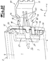
- a securing hook 10 is inserted into an end-side recess of the lamella 2. With an angled portion 11 of the securing hook 10 engages behind the side guide 3, in which it engages in the interior of the hollow box 6. As a result, the lamella with the securing hooks 11 is secured against being pulled out in the lateral direction from the side guide 3. Expediently remains in the unloaded normal state between the angled portion 11 and the inside of the hollow box 6, a gap b, which is closed only by a tensile stress. Then the safety hook 10 is positively supported in the side guide 3, so that further extraction is no longer possible.
- the Fig. 3a shows a detail view of the end portion a of a partially broken blade 2 with a partially partially inserted safety hook 10.
- a plastic cap is attached, which completely borders the end opening of the blade 2 for insertion of the securing hook 10 ,
- the plastic cap 12 now engages with a centering nose 13 in an associated recess in the plate of the plate body 9.
- the plastic cap 12 is held approximately vertically in the vertical direction y on the lamellar body 9.
- the plastic cap 12 is located with a sleeve-shaped portion 14 on both sides of an inner side of the hollow profile and is supported on this.
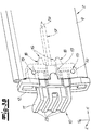
- the securing hook 10 has in addition to the angled portion 11 two integrally adjoining fasteners in the form of latching hooks (16) and arranged therebetween also made of plastic integrally molded pin 17. Starting from the angled section 11 in the lateral direction x, the pin 17 has a greater length than the two latching hooks 16 so that it extends deeper into the interior of the lamella 2 in the installed state.
- the latching hooks 16 are each equipped with a front-side insertion bevel 18 in the insertion direction and a retaining surface 19 arranged on the rearward side facing away from the insertion direction.
- the thus formed hook-shaped portion is connected in each case by an elastically deformable support arm 20 with the remaining safety hook 10.
- the latching hooks 16 are compressed when hitting an obstacle in the direction of the pin 17. After overcoming the obstacle, you automatically spring back apart elastically.
- the holding surface 19 is according to Art a barb so inclined that the latching hooks are pulled apart in a subsequent tensile stress, so that the latching connection reinforced.
- an abutment 21 is provided within the sleeve-shaped portion 14, which on the one hand interact with the insertion bevel 18 during insertion of the latching hook 10 for compression of the latching hooks 16 and on the other hand a positive contact surface for the retaining surfaces 19 of the securing hook 10th form.
- securing hook 10 is provided with stabilizing ribs 23 both in the region of the angled section 11 and in the transition to the pin 17 and the latching hook 16. This is especially by a comparative consideration with the Fig. 4 , which represents the safety hook alone, clearly.
- the pin 17 further has a sharpened end 24, with which it is driven into a filling of the disk body 9. By the elongated shape of the pin 17, this is then supported in the insulation over its entire length dipping in this in the height direction y and the thickness direction z and can transmit forces in both directions.
- the pin 17 has a greater extension in the thickness direction z than in the vertical direction y in cross-section.
- the cross section is formed in the embodiment in approximately rectangular with beveled edges.
- a gap 25 which opens into limited by a circular arc segment bulges 26.
- the diameter of the bulges 26 is greater than the width of the gap 25th
Abstract
Die Erfindung betrifft ein Rolltor mit zumindest einem eine Lamelle (2) aufweisenden Torblatt (1) und mit Seitenführungen (3), an denen das Torblatt (1) verschiebbar geführt ist. In die Seitenführungen (3) tauchen Endbereiche (a) der Lamelle (2) ein. Die Lamelle (2) ist gegen das Herausziehen aus zumindest einer Seitenführung (3) durch einen die Seitenführung (3) hintergreifenden Spritzguss-Sicherungshaken (10) gesichert. Erfindungsgemäß ist der Spritzguss-Sicherungshaken (10) in eine endseitige Ausnehmung der Lamelle (2) eingesetzt und ausschließlich durch zumindest zwei Befestigungselemente mit der Lamelle (2) verbunden. Der Spritzguss-Sicherungshaken (10) weist einen einstückig angeformten Stift (17) auf, der sich tiefer in die Lamelle (2) hineinerstreckt als die Befestigungselemente.The invention relates to a roller shutter with at least one lamella (2) having a door leaf (1) and with side guides (3) on which the door leaf (1) is displaceably guided. End sections (a) of the lamella (2) enter the side guides (3). The lamella (2) is secured against being pulled out of at least one lateral guide (3) by an injection-molded securing hook (10) engaging behind the lateral guide (3). According to the invention, the injection-molded safety hook (10) is inserted into an end-side recess of the lamella (2) and is connected to the lamella (2) exclusively by at least two fastening elements. The injection-molded safety hook (10) has an integrally molded pin (17) which extends deeper into the blade (2) than the fasteners.
Description
Die Erfindung betrifft ein Rolltor mit einem zumindest eine Lamelle aufweisenden Torblatt und mit Seitenführungen, an denen das Torblatt verschiebbar geführt ist und in welche die Endbereiche der Lamelle eintauchen. Dabei ist die Lamelle gegen das Herausziehen aus zumindest einer Seitenführung durch einen die Seitenführung hintergreifenden Spritzguss-Sicherungshaken gesichert.The invention relates to a roller door with a door leaf having at least one lamella and with side guides on which the door leaf is displaceably guided and into which the end regions of the lamella are immersed. In this case, the lamella is secured against pulling out of at least one side guide by a side guide engaging behind injection-safety catch.
Bei Rolltoren in Lamellenbauweise - beispielsweise bei Rollläden - werden die Seitenführungen üblicherweise ohne bewegliche Teile, d. h., insbesondere ohne Rollen verwirklicht. Beide Endbereiche jeder Lamelle sind dabei jeweils seitlich von einer eine Seitenführung bildenden Seitenschiene dreiseitig umgriffen, so dass die Bewegung einer Lamelle auf die Vertikale entlang der Seitenschiene begrenzt ist. Ein zusätzlicher Freiheitsgrad des Herausziehens aus der Schiene wird durch eine spiegelbildlich angeordnete zweite Schiene am gegenüberliegenden Ende der Lamelle eliminiert. Die Bewegung des Torblattes ist somit auf eine lineare Bewegung - vorzugsweise in Vertikalrichtung - festgelegt.In roller shutters in lamellar construction - for example, shutters - the side guides are usually without moving parts, d. h., Realized in particular without roles. Both end areas of each slat are in each case laterally encompassed on three sides by a lateral rail forming a lateral guide, so that the movement of a slat is limited to the vertical along the side rail. An additional degree of freedom of extraction from the rail is eliminated by a mirror-image arranged second rail at the opposite end of the blade. The movement of the door leaf is thus fixed to a linear movement - preferably in the vertical direction.
Aufgrund einer gewissen Biegsamkeit der Torblattlamellen kann es jedoch in Belastungssituationen - insbesondere durch Windlast oder bei Aufbruchsversuchen - passieren, dass sich die Lamellen bis zu einem Punkt durchbiegen, an dem der Endbereich aus der Seitenführung herausgezogen wird. Dies wird zu einer Beschädigung des Torblattes sowie zu einem unkontrollierten und ungewollten Öffnen des durch das Torblatt zu verschließenden Durchganges.Due to a certain flexibility of the door leaf blades, however, it can happen in load situations - in particular by wind load or break-open attempts - that the lamellae sag to a point at which the end portion is pulled out of the side guide. This leads to damage to the door leaf as well as uncontrolled and unintentional opening of the passage to be closed by the door leaf.
Zur Sicherung der Lamellen gegen das Herausziehen aus der Seitenführung sind Sicherungshaken bekannt, welche stirnseitig an den Lamellen befestigt werden und die Seitenführung hintergreifen. Zur Befestigung an der Lamelle und zur Stabilisierung werden die Sicherungshaken dabei mit der Lamelle verschraubt. Hierdurch fällt jedoch ein erheblicher Installationsaufwand an und es muss auch an der Lamelle eine Einrichtung zur Aufnahme und Befestigung der Schraube vorgesehen werden.To secure the slats against pulling out of the side guide locking hooks are known, which is attached to the front side of the slats be and engage the side guide. For attachment to the lamella and for stabilization, the safety hooks are screwed to the lamella. However, this results in a considerable installation effort and it must also be provided on the blade means for receiving and fastening the screw.
Vor diesem Hintergrund liegt der Erfindung die Aufgabe zugrunde, den Installationsaufwand für die Spritzguss-Sicherungshaken zu verringern ohne dabei die Stabilität und Wirksamkeit der Sicherung zu vermindern.Against this background, the invention has for its object to reduce the installation cost of the injection-molded safety hook without reducing the stability and effectiveness of the fuse.
Gegenstand der Erfindung und Lösung dieser Aufgabe ist ein Rolltor nach Anspruch 1 sowie ein Sicherungshaken gemäß Anspruch 11. Bevorzugte Ausgestaltungen sind in den abhängigen Unteransprüchen angegeben.The invention and solution of this problem is a roller door according to claim 1 and a safety hook according to
Erfindungsgemäß ist der Spritzguss-Sicherungshaken in eine endseitige Ausnehmung der Lamelle eingesetzt und ausschließlich durch zumindest zwei Befestigungselemente mit der Lamelle - direkt oder indirekt - verbunden. Weiterhin weist der Sicherungshaken einen einstückig angeformten Stift auf, der sich tiefer in die Lamelle hineinerstreckt als die Befestigungselemente. Der Stift besteht vorzugsweise aus Kunststoff und ist zwischen den Befestigungselementen angeordnet. Durch den Stift wird eine zusätzliche Stabilisierung bereitgestellt, welche einerseits ein Abkippen des Sicherungshakens bei einer Zugbelastung und andererseits - durch innenseitigen Formschluss - eine Biegung der Lamelle verhindert.According to the invention, the injection-molded safety hook is inserted into an end-side recess of the lamella and connected exclusively by at least two fastening elements with the lamella-directly or indirectly. Furthermore, the safety hook has an integrally molded pin, which extends deeper into the blade than the fasteners. The pin is preferably made of plastic and is disposed between the fasteners. By the pin additional stabilization is provided, which on the one hand prevents tilting of the safety hook in a tensile load and on the other hand - by internal positive locking - a bending of the blade.
In einer bevorzugten Ausgestaltung erstreckt sich der Stift zumindest doppelt so tief in die Lamelle hinein wie die Befestigungselemente. Hierdurch wird ein besonders guter Verkippschutz für den Sicherungshaken und gleichzeitig eine besonders gute Stabilisierung der Lamelle erzielt.In a preferred embodiment, the pin extends at least twice as deep into the blade as the fasteners. As a result, a particularly good tilt protection for the safety hook and at the same time a particularly good stabilization of the blade is achieved.
In einer bevorzugten Ausgestaltung ist der Stift an seinem Ende angespitzt ausgebildet. Hierdurch wird einerseits das Einführen des Sicherungshakens in die zugeordnete Ausnehmung der Lamelle vereinfacht, da sich eine natürliche Einführschräge ergibt. Andererseits kann der Stift hierdurch auch in ein verformbares bzw. verdrängbares Material im Innern der Lamelle eingedrückt werden. Hierdurch verbessert sich die Kraftübertragung auf die Lamelle.In a preferred embodiment, the pin is pointed sharpened at its end. As a result, on the one hand, the insertion of the safety hook is simplified in the associated recess of the blade, since there is a natural insertion bevel. On the other hand, the pin can thereby also be pressed into a deformable or displaceable material in the interior of the lamella. This improves the power transmission to the lamella.
In einer besonders bevorzugten Ausgestaltung ist die Lamelle als Hohlprofil ausgebildet. Hohlprofile lassen sich mit relativ geringem Materialaufwand und hoher Biegesteifigkeit herstellen. Weiterhin kann der innere Hohlraum gleichzeitig zur Aufnahme des Sicherungshakens dienen.In a particularly preferred embodiment, the lamella is designed as a hollow profile. Hollow profiles can be produced with relatively little material and high bending stiffness. Furthermore, the inner cavity can simultaneously serve to receive the safety hook.
In einer besonders bevorzugten Ausgestaltung ist die als Hohlprofil ausgebildete Lamelle zumindest teilweise mit Kunststoffschaum gefüllt. Dabei erstreckt sich der Stift bis in den Kunststoffschaum. Geschäumte Kunststoffmaterialien - beispielsweise PU-Schaum - weisen eine gute Formstabilität, geringes Gewicht und gleichzeitig eine gute thermische Isolierwirkung auf. Durch die zwischenliegende Schaumschicht kann der Stift im Bereich des Hohlprofils mit der Außenwandung der Lamelle mechanisch gekoppelt werden, ohne mit dieser direkt in Kontakt treten zu müssen. Somit entfallen Klapper- bzw. Schlaggeräusche im Belastungsfall. Ein angespitzter Stift kann überdies direkt durch den Einschiebevorgang in das Schaumstoffmaterial hineingetrieben werden. Dazu muss vor dem Einschieben keine separate Aufnahmeausnehmung bereitgestellt werden. Durch eine seitliche Verdrängung beim Hineintreiben des Stifts in das Kunststoffschaummaterial wird der Schaum zusätzlich komprimiert, was zu einer verbesserten seitlichen Abstützung führt.In a particularly preferred embodiment, the lamella designed as a hollow profile is at least partially filled with plastic foam. The pen extends into the plastic foam. Foamed plastic materials - for example PU foam - have a good dimensional stability, low weight and at the same time a good thermal insulation effect. Due to the intermediate foam layer, the pin can be mechanically coupled in the region of the hollow profile with the outer wall of the blade without having to come into direct contact with this. Thus, rattling or impact noise accounts in the case of load. A sharpened pen can also be driven directly into the foam material by the insertion process. For this purpose, no separate receiving recess must be provided before insertion. By a lateral displacement when driving the pin in the plastic foam material, the foam is additionally compressed, resulting in an improved lateral support.
Zweckmäßigerweise weist die Lamelle endseitig eine Kunststoffkappe auf. Diese bildet eine formschlüssige Aufnahme für den Sicherungshaken. Gleichzeitig kann die Kunststoffkappe auch das Widerlager für die Rastverbindung des Sicherungshakens bilden. Gleichzeitig ist die Kunststoffkappe zweckmäßigerweise ihrerseits mit einer Rastverbindung an dem Endbereich der Lamelle gehalten. Diese kann durch das Einschieben des Sicherungshakens blockiert sein, so dass eine zerstörungsfreie Trennung zwischen Endkappe und Lamellenkörper nicht möglich ist.Conveniently, the blade has a plastic cap on the end. This forms a positive receptacle for the safety hook. At the same time, the plastic cap can also form the abutment for the latching connection of the safety hook. At the same time the plastic cap is suitably held in turn with a latching connection to the end portion of the blade. This can be blocked by the insertion of the safety hook, so that a non-destructive separation between the end cap and lamellar body is not possible.
In einer bevorzugten Ausgestaltung besteht das Torblatt auf einer Vielzahl von paarweise miteinander schwenkbeweglich verbundenen Lamellen. Die Vielzahl der einzelnen Lamellen bildet das Torblatt, welches jeweils entlang der Schwenkachsen zwischen zwei benachbarten Lamellen abgewinkelt und somit aufgerollt werden kann.In a preferred embodiment, the door leaf on a plurality of pairs with each other pivotally connected slats. The plurality of individual slats forms the door leaf, which in each case angled along the pivot axes between two adjacent slats and thus can be rolled up.
Zweckmäßigerweise weist das Tor eine Wickelwelle auf, auf der das Torblatt zur Öffnung aufgerollt werden kann. Bei einer Aufwickelbewegung verschiebt sich das Torblatt entlang der Seitenführungen in Richtung der Wickelwelle.Conveniently, the gate has a winding shaft on which the door leaf can be rolled up to the opening. During a winding movement, the door leaf shifts along the side guides in the direction of the winding shaft.
In einer bevorzugten Ausgestaltung der Erfindung sind die Befestigungselemente als Rasthaken ausgebildet.In a preferred embodiment of the invention, the fastening elements are designed as latching hooks.
Die Rasthaken weisen in Einschubrichtung vorderseitig eine Einführschräge und an der hiervon abgewandten in Einschubrichtung rückwärtigen Seite eine Haltefläche auf. Diese Rasthaken sind durch einen elastisch verformbaren Haltearm so mit dem Hauptteil des Sicherungshakens verbunden, dass sie beim Einschieben in eine Schmalseite der Lamelle an einem zugeordneten Widerlager der Lamelle vorbeigeführt werden können. Bei Erreichen der vorgesehenen Einschubtiefe werden die elastischen Haltearme entspannt, so dass die Rückhalteflächen mit dem jeweils zugeordneten Widerlager formschlüssig in Anlage gelangen. Hierdurch wird der Sicherungshaken seinerseits gegen ein Herausziehen aus dem Endbereich der Lamelle gesichert.The latching hooks have in the insertion direction on the front side an insertion bevel and on the side facing away from this in the insertion direction on the rear side a holding surface. These latching hooks are connected by an elastically deformable support arm so with the main part of the safety hook that they can be passed when pushed into a narrow side of the blade to an associated abutment of the lamella. Upon reaching the intended insertion depth, the elastic holding arms are relaxed, so that the retaining surfaces with the respective associated abutment engage positively in contact. As a result, the securing hook is in turn secured against being pulled out of the end region of the lamella.
Gleichzeitig wird der Montageaufwand drastisch reduziert: Der Stift und der Rasthaken müssen lediglich in eine zugeordnete Ausnehmung der Lamelle eingeführt und durch Kraftwirkung soweit eingeschoben werden, dass die Rasthaken formschlüssig in der Lamelle befestigt sind. Eine zusätzliche Sicherungsschraube, die ihrerseits mit einem zugeordneten Innengewinde in Eingriff gebracht und verschraubt werden muss, entfällt gänzlich.At the same time, the assembly effort is drastically reduced: The pin and the latching hook need only be inserted into an associated recess of the blade and pushed far enough by the effect of force that the latching hooks are positively secured in the blade. An additional locking screw, which in turn must be engaged with an associated internal thread and screwed, deleted entirely.
In einer alternativen Ausgestaltung der Erfindung sind die Befestigungselemente als Aufnahmen für Schrauben und/oder Nieten ausgebildet.In an alternative embodiment of the invention, the fastening elements are designed as receptacles for screws and / or rivets.
Gegenstand der Erfindung ist auch ein einstückig vorzugsweise aus Kunststoff, geformter Spritzguss-Sicherungshaken zur Verwendung in einem zuvor beschriebenen Rolltor.The invention is also an integrally preferably made of plastic molded injection-security locking hooks for use in a previously described roller door.
Die Erfindung wird nachfolgend anhand lediglich ein Ausführungsbeispiel darstellenden Zeichnungen erläutert. Es zeigen schematisch:
- Fig. 1
- eine perspektivische Darstellung eines erfindungsgemäßen Rolltores im halbgeöffneten Zustand,
- Fig. 2
- Horizontalschnitt durch das Rolltor gemäß
Fig. 1 entlang einer Ebene A-A, - Fig. 3a
- den Endbereich einer Torblattlamelle mit einem erfindungsgemäßen Sicherungshaken in teilweise eingeschobenem Zustand
- Fig. 3b
- Rückansicht der Darstellung aus
Fig. 3a mit vollständig eingeschobenem Sicherungshaken und - Fig. 4
- eine perspektivische Darstellung eines erfindungsgemäßen Sicherungshakens.
- Fig. 1
- a perspective view of a roll-up door according to the invention in the half-opened state,
- Fig. 2
- Horizontal section through the roller door according to
Fig. 1 along a plane AA, - Fig. 3a
- the end region of a Torblattlamelle with a safety hook according to the invention in partially inserted state
- Fig. 3b
- Rear view of the presentation
Fig. 3a with fully inserted safety hook and - Fig. 4
- a perspective view of a safety hook according to the invention.
In der
Wie man der
Erfindungsgemäß ist ein Sicherungshaken 10 in eine endseitige Ausnehmung der Lamelle 2 eingesetzt. Mit einem abgewinkelten Abschnitt 11 hintergreift der Sicherungshaken 10 die Seitenführung 3, in dem es in den Innenraum des Hohlkastens 6 eingreift. Dadurch wird die Lamelle mit den Sicherungshaken 11 gegen ein Herausziehen in der Seitenrichtung aus der Seitenführung 3 gesichert. Zweckmäßigerweise verbleibt im unbelasteten Normalzustand zwischen dem abgewinkelten Abschnitt 11 und der Innenseite des Hohlkastens 6 ein Spalt b, der erst durch eine Zugbeanspruchung geschlossen wird. Dann ist der Sicherungshaken 10 formschlüssig in der Seitenführung 3 abgestützt, so dass ein weiteres Herausziehen nicht mehr möglich ist.According to the invention, a securing
Die
Der Sicherungshaken 10 weist neben dem abgewinkelten Abschnitt 11 zwei daran einstückig anschließende Befestigungselemente in Form von Rasthaken (16) sowie einen dazwischen angeordneten ebenfalls aus Kunststoff einstückig angeformten Stift 17 auf. Der Stift 17 weist ausgehend von dem abgewinkelten Abschnitt 11 in der Seitenrichtung x eine größere Länge auf als die beiden Rasthaken 16, so dass er sich im montierten Zustand tiefer als diese in den Innenraum der Lamelle 2 erstreckt.The securing
Die Rasthaken 16 werden jeweils mit einer in Einschubrichtung vorderseitigen Einführschräge 18 sowie einer an der hiervon abgewandten Einschubrichtung rückwärtigen Seite angeordneten Haltefläche 19 ausgestattet. Der hierdurch gebildete hakenförmige Abschnitt wird jeweils durch einen elastisch verformbaren Haltearm 20 mit dem übrigen Sicherungshaken 10 verbunden. Bei einer Einschubbewegung in der Querrichtung x längs zur Haupterstreckung des Stiftes 17 werden die Rasthaken 16 bei Auftreffen auf ein Hindernis in Richtung des Stiftes 17 zusammengedrückt. Nach Überwinden des Hindernisses federn Sie selbsttätig elastisch wieder auseinander. Die Haltefläche 19 ist nach Art eines Widerhakens so schräg gestellt, dass die Rasthaken bei einer anschließenden Zugbeanspruchung auseinandergezogen werden, so dass sich die Rastverbindung verstärkt.The latching hooks 16 are each equipped with a front-
Zur Wechselwirkung mit den Rasthaken 16 ist innerhalb des hülsenförmigen Abschnitts 14 jeweils ein Widerlager 21 vorgesehen, welches einerseits in Wechselwirkung mit der Einführschräge 18 beim Einschieben des Rasthakens 10 für eine Komprimierung der Rasthaken 16 sorgen und andererseits eine formschlüssige Anlagefläche für die Halteflächen 19 des Sicherungshakens 10 bilden.For interaction with the latching hooks 16, an
An die Rasthaken 16 anschließend sind an den Sicherungshaken 10 Anlageschultern 22 angeformt, welche bei einem vollständigen Einschieben in die Kunststoffkappe 2 an dieser formschlüssig abgestützt sind.At the latching hooks 16 then 10
In der Rückansicht gemäß
Der Stift 17 weist ferner ein angespitztes Ende 24 auf, mit dem es in eine Füllung des Lamellenkörpers 9 eingetrieben ist. Durch die längliche Form des Stiftes 17 ist dieser dann in der Dämmung über seine gesamte in diese eintauchende Länge in der Höhenrichtung y und der Dickenrichtung z abgestützt und kann in beiden Richtungen Kräfte übertragen.The
Um Biegekräfte aufgrund von Windbelastungen senkrecht zur Torblattebene optimal auffangen zu können, weist der Stift 17 im Querschnitt eine größere Erstreckung in der Dickenrichtung z als in der Höhenrichtung y auf. Dabei ist der Querschnitt im Ausführungsbeispiel in etwa rechteckig mit angefasten Kanten ausgebildet. Zwischen den Rasthaken 16 und dem Stift 17 verläuft jeweils ein Spalt 25, der in durch ein Kreisbogensegment begrenzten Ausbuchtungen 26 mündet. Der Durchmesser der Ausbuchtungen 26 ist dabei größer als die Breite des Spalts 25.In order to optimally absorb bending forces due to wind loads perpendicular to the door leaf level, the
Claims (12)
Applications Claiming Priority (1)
| Application Number | Priority Date | Filing Date | Title |
|---|---|---|---|
| DE102016125677.3A DE102016125677A1 (en) | 2016-12-23 | 2016-12-23 | slat roll-up door |
Publications (1)
| Publication Number | Publication Date |
|---|---|
| EP3339560A1 true EP3339560A1 (en) | 2018-06-27 |
Family
ID=59829274
Family Applications (1)
| Application Number | Title | Priority Date | Filing Date |
|---|---|---|---|
| EP17190083.0A Withdrawn EP3339560A1 (en) | 2016-12-23 | 2017-09-08 | Lamellae roller gate and safety hook |
Country Status (2)
| Country | Link |
|---|---|
| EP (1) | EP3339560A1 (en) |
| DE (1) | DE102016125677A1 (en) |
Cited By (1)
| Publication number | Priority date | Publication date | Assignee | Title |
|---|---|---|---|---|
| DE102022117412A1 (en) | 2021-08-06 | 2023-02-09 | Hörmann Kg Dissen | Storm anchor end piece for roller door profiles and uses of the same |
Families Citing this family (1)
| Publication number | Priority date | Publication date | Assignee | Title |
|---|---|---|---|---|
| DE102020116649B3 (en) | 2020-06-24 | 2021-12-23 | Jäger - Engineering GmbH | Machine door and machine |
Citations (5)
| Publication number | Priority date | Publication date | Assignee | Title |
|---|---|---|---|---|
| BE636358A (en) * | ||||
| DE4301070A1 (en) * | 1992-11-26 | 1994-06-01 | Gustav Stange | Fixture and assembly onto adjacent lamellae of roller shutter or door to prevent slippage - comprises thermoplastic base conforming to front face of lamella with gripping and supporting sections and attaching to face of one lamella |
| EP0794313A1 (en) * | 1996-03-07 | 1997-09-10 | Les Zelles | Hooking system for roller shutter |
| US6068040A (en) * | 1998-07-24 | 2000-05-30 | Alpine Overhead Doors, Inc. | Slat edge retainer for overhead rolling doors |
| DE20106088U1 (en) * | 2000-04-06 | 2001-06-07 | Rapid Sa | Roller shutter device with hinged slats and guide rails for the ends of the slats |
Family Cites Families (2)
| Publication number | Priority date | Publication date | Assignee | Title |
|---|---|---|---|---|
| DE20308668U1 (en) * | 2002-05-24 | 2003-08-28 | Hoermann Kg Dissen | End piece for lamella for roller door is made of single piece of spray-cast plastics has fastening tongues extending into hollow lamella and has profiled slider engaging in guide rail |
| DE102009020079A1 (en) * | 2009-05-06 | 2010-11-11 | Hörmann KG Amshausen | Rolling gate profile bar construction, has attachment mechanism with screwing or rivet attachment mechanism for attaching storm anchor at area of casing, and emboss detection mechanism that is engaged by embossing another area of casing |
-
2016
- 2016-12-23 DE DE102016125677.3A patent/DE102016125677A1/en not_active Withdrawn
-
2017
- 2017-09-08 EP EP17190083.0A patent/EP3339560A1/en not_active Withdrawn
Patent Citations (5)
| Publication number | Priority date | Publication date | Assignee | Title |
|---|---|---|---|---|
| BE636358A (en) * | ||||
| DE4301070A1 (en) * | 1992-11-26 | 1994-06-01 | Gustav Stange | Fixture and assembly onto adjacent lamellae of roller shutter or door to prevent slippage - comprises thermoplastic base conforming to front face of lamella with gripping and supporting sections and attaching to face of one lamella |
| EP0794313A1 (en) * | 1996-03-07 | 1997-09-10 | Les Zelles | Hooking system for roller shutter |
| US6068040A (en) * | 1998-07-24 | 2000-05-30 | Alpine Overhead Doors, Inc. | Slat edge retainer for overhead rolling doors |
| DE20106088U1 (en) * | 2000-04-06 | 2001-06-07 | Rapid Sa | Roller shutter device with hinged slats and guide rails for the ends of the slats |
Cited By (1)
| Publication number | Priority date | Publication date | Assignee | Title |
|---|---|---|---|---|
| DE102022117412A1 (en) | 2021-08-06 | 2023-02-09 | Hörmann Kg Dissen | Storm anchor end piece for roller door profiles and uses of the same |
Also Published As
| Publication number | Publication date |
|---|---|
| DE102016125677A1 (en) | 2018-06-28 |
Similar Documents
| Publication | Publication Date | Title |
|---|---|---|
| EP1580393B1 (en) | Door | |
| EP0167137B1 (en) | Roll-shaped aluminium roller shutter slat with limited dimensions | |
| DE102006005610B4 (en) | Fly screens | |
| EP3339560A1 (en) | Lamellae roller gate and safety hook | |
| EP2354431B1 (en) | Roller blind box with guide rails | |
| DE102005003483A1 (en) | Method for fitting venetian blind into window or door opening with flexible guide rails clipped into rigid support rails each side of the opening | |
| AT517263B1 (en) | Closing device for a sliding door | |
| EP2281995B1 (en) | Roller shutter | |
| EP3489450B1 (en) | Gate | |
| AT508177B1 (en) | ROLLER SHUTTER WITH GUIDE RAILS AND STOPPERS | |
| DE19618912A1 (en) | Slat for a leaf of a roller shutter that can preferably be moved up and down for a gate, a door, a window or the like. Opening | |
| EP2623703B1 (en) | Mounting profile | |
| DE19714112B4 (en) | Blinds for an asymmetric opening | |
| EP3467243B1 (en) | Gate, method of operating same and retrofit kit for a gate | |
| EP0185835B1 (en) | Window shutter | |
| EP2233679B1 (en) | Venetian blind for triangular windows | |
| DE19600951A1 (en) | Slatted blind for door or window of house | |
| DE2501066A1 (en) | SHUTTERS | |
| WO2016192913A1 (en) | Shading device for a pane or a glass roof region of a vehicle interior | |
| DE1155897B (en) | Louvre gate | |
| WO2004029396A1 (en) | High-speed door | |
| EP2089601B1 (en) | Closure device | |
| DE102012019435A1 (en) | Roller shutter and tank connection module for it | |
| DE202015002105U1 (en) | Inclined roller blinds for slanted windows | |
| EP1947286A2 (en) | Roller shutter housing |
Legal Events
| Date | Code | Title | Description |
|---|---|---|---|
| PUAI | Public reference made under article 153(3) epc to a published international application that has entered the european phase |
Free format text: ORIGINAL CODE: 0009012 |
|
| STAA | Information on the status of an ep patent application or granted ep patent |
Free format text: STATUS: THE APPLICATION HAS BEEN PUBLISHED |
|
| AK | Designated contracting states |
Kind code of ref document: A1 Designated state(s): AL AT BE BG CH CY CZ DE DK EE ES FI FR GB GR HR HU IE IS IT LI LT LU LV MC MK MT NL NO PL PT RO RS SE SI SK SM TR |
|
| AX | Request for extension of the european patent |
Extension state: BA ME |
|
| STAA | Information on the status of an ep patent application or granted ep patent |
Free format text: STATUS: REQUEST FOR EXAMINATION WAS MADE |
|
| 17P | Request for examination filed |
Effective date: 20181220 |
|
| RBV | Designated contracting states (corrected) |
Designated state(s): AL AT BE BG CH CY CZ DE DK EE ES FI FR GB GR HR HU IE IS IT LI LT LU LV MC MK MT NL NO PL PT RO RS SE SI SK SM TR |
|
| STAA | Information on the status of an ep patent application or granted ep patent |
Free format text: STATUS: EXAMINATION IS IN PROGRESS |
|
| 17Q | First examination report despatched |
Effective date: 20191030 |
|
| GRAP | Despatch of communication of intention to grant a patent |
Free format text: ORIGINAL CODE: EPIDOSNIGR1 |
|
| STAA | Information on the status of an ep patent application or granted ep patent |
Free format text: STATUS: GRANT OF PATENT IS INTENDED |
|
| INTG | Intention to grant announced |
Effective date: 20201110 |
|
| STAA | Information on the status of an ep patent application or granted ep patent |
Free format text: STATUS: THE APPLICATION IS DEEMED TO BE WITHDRAWN |
|
| 18D | Application deemed to be withdrawn |
Effective date: 20210323 |