EP3339468A1 - Crucible for oled evaporation source and manufacturing method therefor - Google Patents
Crucible for oled evaporation source and manufacturing method therefor Download PDFInfo
- Publication number
- EP3339468A1 EP3339468A1 EP15891412.7A EP15891412A EP3339468A1 EP 3339468 A1 EP3339468 A1 EP 3339468A1 EP 15891412 A EP15891412 A EP 15891412A EP 3339468 A1 EP3339468 A1 EP 3339468A1
- Authority
- EP
- European Patent Office
- Prior art keywords
- crucible
- holes
- evaporation source
- inner plate
- source according
- Prior art date
- Legal status (The legal status is an assumption and is not a legal conclusion. Google has not performed a legal analysis and makes no representation as to the accuracy of the status listed.)
- Withdrawn
Links
Images




Classifications
-
- C—CHEMISTRY; METALLURGY
- C23—COATING METALLIC MATERIAL; COATING MATERIAL WITH METALLIC MATERIAL; CHEMICAL SURFACE TREATMENT; DIFFUSION TREATMENT OF METALLIC MATERIAL; COATING BY VACUUM EVAPORATION, BY SPUTTERING, BY ION IMPLANTATION OR BY CHEMICAL VAPOUR DEPOSITION, IN GENERAL; INHIBITING CORROSION OF METALLIC MATERIAL OR INCRUSTATION IN GENERAL
- C23C—COATING METALLIC MATERIAL; COATING MATERIAL WITH METALLIC MATERIAL; SURFACE TREATMENT OF METALLIC MATERIAL BY DIFFUSION INTO THE SURFACE, BY CHEMICAL CONVERSION OR SUBSTITUTION; COATING BY VACUUM EVAPORATION, BY SPUTTERING, BY ION IMPLANTATION OR BY CHEMICAL VAPOUR DEPOSITION, IN GENERAL
- C23C14/00—Coating by vacuum evaporation, by sputtering or by ion implantation of the coating forming material
- C23C14/22—Coating by vacuum evaporation, by sputtering or by ion implantation of the coating forming material characterised by the process of coating
- C23C14/24—Vacuum evaporation
- C23C14/243—Crucibles for source material
-
- H—ELECTRICITY
- H10—SEMICONDUCTOR DEVICES; ELECTRIC SOLID-STATE DEVICES NOT OTHERWISE PROVIDED FOR
- H10K—ORGANIC ELECTRIC SOLID-STATE DEVICES
- H10K71/00—Manufacture or treatment specially adapted for the organic devices covered by this subclass
-
- H—ELECTRICITY
- H10—SEMICONDUCTOR DEVICES; ELECTRIC SOLID-STATE DEVICES NOT OTHERWISE PROVIDED FOR
- H10K—ORGANIC ELECTRIC SOLID-STATE DEVICES
- H10K71/00—Manufacture or treatment specially adapted for the organic devices covered by this subclass
- H10K71/10—Deposition of organic active material
- H10K71/16—Deposition of organic active material using physical vapour deposition [PVD], e.g. vacuum deposition or sputtering
- H10K71/164—Deposition of organic active material using physical vapour deposition [PVD], e.g. vacuum deposition or sputtering using vacuum deposition
-
- H—ELECTRICITY
- H10—SEMICONDUCTOR DEVICES; ELECTRIC SOLID-STATE DEVICES NOT OTHERWISE PROVIDED FOR
- H10K—ORGANIC ELECTRIC SOLID-STATE DEVICES
- H10K71/00—Manufacture or treatment specially adapted for the organic devices covered by this subclass
- H10K71/40—Thermal treatment, e.g. annealing in the presence of a solvent vapour
Definitions
- the present disclosure relates to a field of display technology, in particular to a crucible for OLED evaporation source and a manufacturing method thereof.
- OLED has become a most potential emerging technology instead of LCD (liquid crystal display).
- OLED technology is in a rapid development stage.
- OLED display products are typically produced by means of evaporating organic materials at home and abroad. Performances of RGB pixels such as color cast, efficiency and so on are dependent on characteristics of evaporated film layers such as uniformity or the like. During the evaporation, the uniformity of the evaporated film layers is directly dependent on a crucible for evaporation source used as a key component in the evaporation.
- an existing crucible for OLED evaporation source has a flat-bottom structure.
- the organic material has a high viscosity and a surface tension effect is presented after the organic material is liquefied. As a result, the organic material is unevenly distributed in the crucible. Thus, a portion of the bottom is exposed during the evaporation, thereby affecting the uniformity of the evaporated organic material.
- An objective of the present disclosure is to solve at least one aspect of the above problems and defects existed in the prior art.
- a crucible for OLED evaporation source comprising a body and an inner plate provided on the body, wherein a bottom of the body is gradually enlarged from down to up in a cross section perpendicular to a length direction of the body.
- the bottom of the body is designed to have a V shape, a U shape or a combined shape thereof in the cross section perpendicular to the length direction of the body.
- the bottom of the body is designed to have a single V shape, two connected V shapes or more connected V shapes in the cross section.
- the bottom of the body is designed to have a single U shape, two connected U shapes or more connected U shapes in the cross section.
- the bottom of the body is designed to have a combined shape of connected V shape and U shape in the cross section.
- the inner plate is designed to have a shape matched with the shape of the bottom of the body in the cross section.
- holes arranged in a predefined arrangement are provided in the inner plate so that material to be evaporated in the crucible is evaporated and deposited onto a substrate of OLED device disposed on or above the crucible, through the holes.
- the projections of the holes in the inner plate onto a horizontal surface perpendicular to a height direction of the body are evenly distributed.
- the projections of the holes in the inner plate onto the XY plane are evenly distributed.
- a plurality of holes in each of the rows extend in the X-axis direction and two adjacent holes of the plurality of holes in each of the rows are spaced apart from each other by a second interval.
- the first interval is equal to the second interval.
- two adjacent rows of holes are aligned with each other.
- each of the holes in one of the rows is aligned with a midpoint of a connecting line between two adjacent holes in the other row.
- the inner plate comprises a middle portion in which the holes are formed.
- the inner plate further comprises side portions at both sides of the middle portion, which cover on a top of the body.
- the evaporation uniformity and the material usage rate may be improved. Further, the influence on the uniformity of evaporated film layer due to too less remained material may be avoided. Thus, the performance of evaporated film layer is greatly improved.
- the crucible 10 comprises a body 12 and an inner plate 14 disposed on the body 12.
- a bottom of the body 12 is designed as a flat-bottom structure.
- the inner plate 14 is designed as a flat plate.
- holes are provided in the inner plate so that material is evaporated and deposited onto a glass substrate (i.e. a substrate for OLED device) disposed on or above the inner plate, through the holes.
- Fig.1a shows a length L of the inner plate 14
- Fig.1b shows a width W and a height H of the body 12 of the crucible.
- a basic concept of the present disclosure is to set the bottom of the crucible as an arc-shaped structure with small curvature or a taper-shaped structure, so as to ensure maximally both a distribution uniformity in the long-side direction (length direction) and a distribution uniformity in the short-side direction (width direction) if there is less organic material.
- the new crucible according to embodiments of the present disclosure is applicable to the organic material which has a common fluidity after being liquefied.
- the existing crucible is not applicable to such organic material which has a common fluidity after being liquefied.
- OLED devices an existing mass-produced mature technology is to prepare the devices by using a vacuum physical vapor deposition process. Specifically, a prepared back plate or substrate is placed into a vacuum chamber, then various organic material layers are evaporated and deposited onto the back plate or substrate by means of heat evaporation so as to form the OLED devices.
- the evaporation process is an important technical routine for producing OLED devices, and the crucible is a necessary component for the evaporation process.
- a structural design of the crucible has an important influence on a film quality and production efficiency of the organic material.
- the organic material is filled into the crucible, then the organic material in a gas form escapes into openings above the crucible when a temperature reaches an evaporation temperature of the material, thereafter, the organic material is deposited onto a surface of the back plate to form a compact evaporation film.
- a RGB (red, green and blue) device is formed by using patterns on a fine metal mask.
- a crucible for OLED evaporation source comprising a body and an inner plate provided on the body.
- a bottom of the body is gradually enlarged from down to up in a cross section perpendicular to a length direction of the body.
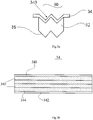
- a schematic cross section view of the crucible for OLED evaporation source according to a first embodiment of the present disclosure in a direction perpendicular to a length direction thereof and a plan view of the inner plate of the crucible are respectively shown.
- the crucible 20 comprises a body 22 and an inner plate 24 provided on the body. As shown, a bottom 26 of the body 22 is designed as a V-shape structure.
- the inner plate 24 is also designed as a V-shape structure, and holes 244 (see Fig.2b ) arranged in a predefined arrangement are provided in the inner plate 24 so that material is evaporated and deposited onto a glass substrate (not shown) disposed above the inner plate 24, through the holes.
- the length direction (sometimes referred to as long-side direction) of the crucible is referred to as a direction in which the length of the crucible extends
- the width direction (sometimes referred to as short-side direction) of the crucible is referred to as a direction in which the width of the crucible extends.
- the bottom 26 of the body 22 is designed as a single V shape in the cross section (i.e. the cross section as shown in Fig.2a ) perpendicular to the length direction.
- Fig.2a shows a width W and a height H of the body 22 of the crucible
- Fig.2b shows a length L of the inner plate 24 (it can be seen combined with Fig.2a that the length of the body 22 is slightly shorter than the length of the inner plate 24).
- specific values of the length L, width W and height H of the crucible may be selected by those skilled in the art as required.
- the length L may be 880mm
- the width W may be 50mm
- the height H may be 120mm.
- the existing crucible is modified into having a bottom of V-shape structure so that the crucible is applicable to the organic material which has a low fluidity after being liquefied. It should be understood that, as the existing crucible is modified into having a bottom of V-shape structure with small curvature, both the distribution uniformity in the long-side direction and the distribution uniformity in the short-side direction may be ensured even if there is less organic material.
- the inner plate 24 comprises side portions 241, 242 at both sides and a middle portion 243 located between the two side portions.
- the two side portions 241, 242 may cover on a top of sides of the body 22.
- other means may be selected by those skilled in the art as required in order to arrange the inner plate 24 on the body 22, instead of the above side portions.
- the middle portion 243 comprises two slant faces 245 in which holes 244 (black points shown in Fig.2 ) arranged in a predefined arrangement are provided.
- projections of the holes 244 in the middle portion 243 onto a horizontal surface perpendicular to the height direction H are evenly or equidistantly distributed.
- the projections of the holes 244 in the middle portion 243 onto the XY plane are evenly or equidistantly distributed.
- the projections onto the XY plane there are multiple rows of holes which are spaced apart from each other by a first interval in the Y-axis direction, a plurality of holes in each of the rows extend in the X-axis direction and two adjacent holes of the plurality of holes in each of the rows are spaced apart from each other by a second interval.
- the first interval is equal to the second interval.
- each of the holes in one of the rows may be aligned with a midpoint of a connecting line between two adjacent holes in the other row, so that the projections of the holes onto the XY plane are evenly distributed, as shown in Fig.2b , for example.
- the evaporated material is evenly deposited onto the substrate of OLED device disposed on or above the crucible.
- the middle portion of the inner plate is formed into the structure of V-shape groove in fact, the fact that the projections of the holes onto the XY plane are evenly distributed means that the holes are not evenly distributed in the slant face of the middle portion.
- a schematic cross section view of the crucible for OLED evaporation source according to a second embodiment of the present disclosure in a direction perpendicular to a length direction thereof and a plan view of the inner plate of the crucible are respectively shown.
- the crucible 30 comprises a body 32 and an inner plate 34 provided on the body. As shown, a bottom 36 of the body 32 is designed as a W-shape structure.
- the inner plate 34 is also designed as a W-shape structure, and holes (see Fig.3b ) arranged in a predefined arrangement are provided in the inner plate 34 so that material is evaporated and deposited onto a glass substrate (not shown) disposed above the inner plate 34, through the holes.
- the bottom 36 of the body 32 is designed as a single W shape in the cross section (i.e. the cross section as shown in Fig.3a ) perpendicular to the length direction. It should be understood that the W shape may be regarded as two connected V shapes.
- the inner plate 34 comprises side portions 341, 342 at both sides and a middle portion 343 located between the two side portions.
- the two side portions 341, 342 may cover on a top of sides of the body 32.
- the middle portion 343 comprises four slant faces 345 in which holes 344 arranged in a predefined arrangement are provided.
- projections of the holes 344 in the middle portion 343 onto a horizontal surface perpendicular to the height direction H are evenly or equidistantly distributed.
- the projections of the holes 344 in the middle portion 343 onto the XY plane are evenly or equidistantly distributed.
- the projections onto the XY plane there are multiple rows of holes which are spaced apart from each other by a first interval in the Y-axis direction, and two adjacent holes in each of the rows are spaced apart from each other by a second interval.
- the first interval is equal to the second interval.
- each of the holes in one of the rows may be aligned with a midpoint of a connecting line between two adjacent holes in the other row, so that the projections of the holes onto the XY plane are evenly distributed, as shown in Fig.3b , for example.
- the existing crucible is modified into having a bottom of W-shape structure so that the crucible is applicable to the organic material which has a low fluidity after being liquefied. It should be understood that, as the existing crucible is modified into having a bottom of W-shape structure with small curvature, both the distribution uniformity in the long-side direction and the distribution uniformity in the short-side direction may be ensured even if there is less organic material.
- a schematic cross section view of the crucible for OLED evaporation source according to a third embodiment of the present disclosure in a direction perpendicular to a length direction thereof and a plan view of the inner plate of the crucible are respectively shown.
- the crucible 40 comprises a body 42 and an inner plate 44 provided on the body 42. As shown, a bottom 46 of the body 42 is designed as a U-shape structure.
- the inner plate 44 is also designed as a U-shape structure, and holes (see Fig.4b ) arranged in a predefined arrangement are provided in the inner plate 44 so that material is evaporated and deposited onto a glass substrate (not shown) disposed above the inner plate 44, through the holes.
- the bottom 46 of the body 42 is designed as a single U shape in the cross section (i.e. the cross section as shown in Fig.4a ) perpendicular to the length direction.
- the inner plate 44 comprises side portions 441, 442 at both sides and a middle portion 443 located between the two side portions.
- the two side portions 441, 442 may cover on a top of sides of the body 42.
- the middle portion 443 comprises a U-shape curved face 445 in which holes 444 arranged in a predefined arrangement are provided.
- projections of the holes 444 in the middle portion 443 onto a horizontal surface perpendicular to the height direction H are evenly or equidistantly distributed.
- the projections of the holes 444 in the middle portion 443 onto the XY plane are evenly or equidistantly distributed.
- the projections onto the XY plane there are multiple rows of holes which are spaced apart from each other by a first interval in the Y-axis direction, and two adjacent holes in each of the rows are spaced apart from each other by a second interval.
- the first interval is equal to the second interval.
- each of the holes in one of the rows may be aligned with a midpoint of a connecting line between two adjacent holes in the other row, so that the projections of the holes onto the XY plane are evenly distributed, as shown in Fig.4b , for example.
- the existing crucible is modified into having a bottom of U-shape structure so that the crucible is applicable to the organic material which has a low fluidity after being liquefied. It should be understood that, as the existing crucible is modified into having a bottom of arc-shape structure with small curvature, both the distribution uniformity in the long-side direction and the distribution uniformity in the short-side direction may be ensured even if there is less organic material.
- a schematic cross section view of the crucible for OLED evaporation source according to a fourth embodiment of the present disclosure in a direction perpendicular to a length direction thereof and a plan view of the inner plate of the crucible are respectively shown.
- the crucible 50 comprises a body 52 and an inner plate 54 provided on the body 52. As shown, a bottom 56 of the body 52 is designed as a structure of two connected U shapes.
- the inner plate 44 is also designed as a structure of two connected U shapes, and holes (see Fig.5b ) arranged in a predefined arrangement are provided in the inner plate 54 so that material is evaporated and deposited onto a glass substrate (not shown) disposed above the inner plate 54, through the holes.
- the bottom 56 of the body 52 is designed as the structure of two connected U shapes in the cross section (i.e. the cross section as shown in Fig.5a ) perpendicular to the length direction.
- the inner plate 54 comprises side portions 541, 542 at both sides and a middle portion 543 located between the two side portions.
- the two side portions 541, 542 may cover on a top of sides of the body 52.
- the middle portion 543 comprises two U-shape curved faces 545 in which holes 544 arranged in a predefined arrangement are provided.
- projections of the holes 544 in the middle portion 543 onto a horizontal surface perpendicular to the height direction H are evenly or equidistantly distributed.
- the projections of the holes 544 in the middle portion 543 onto the XY plane are evenly or equidistantly distributed.
- the projections onto the XY plane there are multiple rows of holes which are spaced apart from each other by a first interval in the Y-axis direction, and two adjacent holes in each of the rows are spaced apart from each other by a second interval.
- the first interval is equal to the second interval.
- each of the holes in one of the rows may be aligned with a midpoint of a connecting line between two adjacent holes in the other row, so that the projections of the holes onto the XY plane are evenly distributed, as shown in Fig.5b , for example.
- the existing crucible is modified into having a bottom of the structure of two connected U shapes so that the crucible is applicable to the organic material which has a low fluidity after being liquefied. It should be understood that, as the existing crucible is modified into having a bottom of arc-shape structure with small curvature, both the distribution uniformity in the long-side direction and the distribution uniformity in the short-side direction may be ensured even if there is less organic material.
- the crucible 60 comprises a body 62 and an inner plate 64 provided on the body 62.
- a bottom 66 of the body 62 is designed as a structure of multiple connected V shapes.
- the inner plate 64 is also designed as a structure of multiple connected V shapes, and holes arranged in a predefined arrangement are provided in the inner plate 64 so that material is evaporated and deposited onto a glass substrate (not shown) disposed above the inner plate 64, through the holes.
- the bottom 66 of the body 62 is designed as the structure of multiple connected V shapes in the cross section (i.e. the cross section as shown in Fig.6 ) perpendicular to the length direction.
- the structures in the embodiment shown in Fig.6 is substantially same as that in the second embodiment, except that the middle portion 643 of the inner plate 64 is designed as the structure of multiple V shapes in the cross section.
- the specific arrangements with regard to the inner plate and the hole distribution are not described in detail here.
- the crucible is designed to have a bottom of the structure of multiple connected V shapes, both the distribution uniformity in the long-side direction and the distribution uniformity in the short-side direction may be ensured even if there is less organic material.
- the crucible 70 comprises a body 72 and an inner plate 74 provided on the body 72.
- a bottom 76 of the body 72 is designed as a structure of multiple connected U shapes.
- the inner plate 74 is also designed as a structure of multiple connected U shapes, and holes arranged in a predefined arrangement are provided in the inner plate 74 so that material is evaporated and deposited onto a glass substrate (not shown) disposed above the inner plate 74, through the holes.
- the bottom 76 of the body 72 is designed as the structure of multiple connected U shapes in the cross section (i.e. the cross section as shown in Fig.7 ) perpendicular to the length direction.
- the structures in the embodiment shown in Fig.7 is substantially same as that in the fourth embodiment, except that the middle portion 743 of the inner plate 74 is designed as the structure of multiple U shapes in the cross section perpendicular to the length direction.
- the specific arrangements with regard to the inner plate and the hole distribution are not described in detail here.
- the crucible is designed to have a bottom of the structure of multiple connected U shapes, that is, the existing crucible is modified into having a bottom of arc-shape structure with small curvature, both the distribution uniformity in the long-side direction and the distribution uniformity in the short-side direction may be ensured even if there is less organic material.
- the bottom of the crucible may have a structure of combined V shape and U shape
- the bottom having such structure may be obtained by those skilled in the art based on the above structures illustrated in the above various embodiments.
- Those skilled in the art may also set specific combined manners of V shape and U shape as required, which are not further described in detail here. It can be understood from the above examples that the technical problems may be solved as long as the bottom of the body of the crucible is designed to enlarge gradually from down to up in the cross section perpendicular to the length direction of the body. Therefore, the specific shapes of the bottom of the body of the crucible may be selected as required, rather than limiting to the shapes illustrated in the above examples.
- another aspect of the present disclosure further provides a manufacturing method of the above crucible for OLED evaporation source, comprising:
- crucible for OLED evaporation source which has a bottom of taper-shape groove structure or arc-shape structure so as to avoid the influence on the uniformity of evaporated material caused by a reduction of amount of the remained material due to an evaporation of a great quantity of material and to improve the uniformity of evaporated material and usage rate of material effectively.
- the conventional crucible has a flat-bottom structure.
- the organic material itself has a high viscosity and a surface tension effect is presented after the organic material is liquefied.
- the organic material is unevenly distributed in the crucible.
- a portion of the bottom is exposed during the evaporation, thereby affecting the uniformity of the evaporated organic material.
- the bottom of the body is designed to have a V shape, U shape or combined shape thereof, so as to improve the distribution uniformity of the liquefied organic material, thereby improving the evaporation uniformity and the usage rate of the material.
Landscapes
- Chemical & Material Sciences (AREA)
- Engineering & Computer Science (AREA)
- Manufacturing & Machinery (AREA)
- Chemical Kinetics & Catalysis (AREA)
- Materials Engineering (AREA)
- Mechanical Engineering (AREA)
- Metallurgy (AREA)
- Organic Chemistry (AREA)
- Electroluminescent Light Sources (AREA)
- Physical Vapour Deposition (AREA)
Abstract
Description
- The present disclosure relates to a field of display technology, in particular to a crucible for OLED evaporation source and a manufacturing method thereof.
- With people to pursuit of higher quality display product, OLED has become a most potential emerging technology instead of LCD (liquid crystal display). OLED technology is in a rapid development stage. OLED display products are typically produced by means of evaporating organic materials at home and abroad. Performances of RGB pixels such as color cast, efficiency and so on are dependent on characteristics of evaporated film layers such as uniformity or the like. During the evaporation, the uniformity of the evaporated film layers is directly dependent on a crucible for evaporation source used as a key component in the evaporation.
- However, an existing crucible for OLED evaporation source has a flat-bottom structure. In addition, the organic material has a high viscosity and a surface tension effect is presented after the organic material is liquefied. As a result, the organic material is unevenly distributed in the crucible. Thus, a portion of the bottom is exposed during the evaporation, thereby affecting the uniformity of the evaporated organic material.
- To this end, it is necessary to provide a new crucible for OLED evaporation source and a manufacturing method thereof which are capable of solving at least a part of the above problems.
- An objective of the present disclosure is to solve at least one aspect of the above problems and defects existed in the prior art.
- According to an aspect of the present disclosure, it is provided a crucible for OLED evaporation source, comprising a body and an inner plate provided on the body, wherein a bottom of the body is gradually enlarged from down to up in a cross section perpendicular to a length direction of the body.
- In an example, the bottom of the body is designed to have a V shape, a U shape or a combined shape thereof in the cross section perpendicular to the length direction of the body.
- In an example, the bottom of the body is designed to have a single V shape, two connected V shapes or more connected V shapes in the cross section.
- In an example, the bottom of the body is designed to have a single U shape, two connected U shapes or more connected U shapes in the cross section.
- In an example, the bottom of the body is designed to have a combined shape of connected V shape and U shape in the cross section.
- In an example, the inner plate is designed to have a shape matched with the shape of the bottom of the body in the cross section.
- In an example, holes arranged in a predefined arrangement are provided in the inner plate so that material to be evaporated in the crucible is evaporated and deposited onto a substrate of OLED device disposed on or above the crucible, through the holes.
- In an example, the projections of the holes in the inner plate onto a horizontal surface perpendicular to a height direction of the body are evenly distributed.
- In an example, in a coordinate system which is established by setting a length direction of the body as X-axis, the width direction of the body as Y-axis and the height direction of the body as Z-axis, the projections of the holes in the inner plate onto the XY plane are evenly distributed.
- In an example, among the projections onto the XY plane, there are multiple rows of holes which are spaced apart from each other by a first interval in the Y-axis direction, a plurality of holes in each of the rows extend in the X-axis direction and two adjacent holes of the plurality of holes in each of the rows are spaced apart from each other by a second interval.
- In an example, the first interval is equal to the second interval.
- In an example, two adjacent rows of holes are aligned with each other.
- In an example, if two adjacent rows of holes are not aligned with each other, each of the holes in one of the rows is aligned with a midpoint of a connecting line between two adjacent holes in the other row.
- In an example, the inner plate comprises a middle portion in which the holes are formed.
- In an example, the inner plate further comprises side portions at both sides of the middle portion, which cover on a top of the body.
- According to another aspect of the present disclosure, it is provided a manufacturing method of a crucible for OLED evaporation source according to claim 1, comprising:
- providing a crucible having a body, a bottom of the body being gradually enlarged from down to up in a cross section perpendicular to a length direction of the body; and
- disposing an inner plate on an upper end of the body of the crucible.
- In the embodiments of the present disclosure, by improving or optimizing the structure of the crucible (specifically, the structure of the bottom of the crucible), the evaporation uniformity and the material usage rate may be improved. Further, the influence on the uniformity of evaporated film layer due to too less remained material may be avoided. Thus, the performance of evaporated film layer is greatly improved.
- These and/or other aspects and advantages of the present disclosure will become apparent and more readily understood from the following description of the preferred embodiments with reference to accompanying drawings, wherein:
-
Figs. 1a and 1b are a schematic cross section view of an existing crucible for OLED evaporation source in a direction perpendicular to a width direction thereof and a schematic cross section view of the existing crucible for OLED evaporation source in a direction perpendicular to a longitudinal or length direction thereof, respectively; -
Figs.2a and 2b are a schematic cross section view of the crucible for OLED evaporation source according to a first embodiment of the present disclosure in a direction perpendicular to a length direction thereof and a plan view of the inner plate of the crucible, respectively; -
Figs.3a and 3b are a schematic cross section view of the crucible for OLED evaporation source according to a second embodiment of the present disclosure in a direction perpendicular to a length direction thereof and a plan view of the inner plate of the crucible, respectively; -
Figs.4a and 4b are a schematic cross section view of the crucible for OLED evaporation source according to a third embodiment of the present disclosure in a direction perpendicular to a length direction thereof and a plan view of the inner plate of the crucible, respectively; -
Figs.5a and 5b are a schematic cross section view of the crucible for OLED evaporation source according to a fourth embodiment of the present disclosure in a direction perpendicular to a length direction thereof and a plan view of the inner plate of the crucible, respectively; -
Figs.6 is a schematic cross section view of the crucible for OLED evaporation source according to a fifth embodiment of the present disclosure in a direction perpendicular to a length direction thereof; and -
Figs.7 is a schematic cross section view of the crucible for OLED evaporation source according to a sixth embodiment of the present disclosure in a direction perpendicular to a length direction thereof. - Technical solutions of the present disclosure will be further described in detail by means of the following embodiments in conjunction with the accompanying drawings 1 -7. In the specification, the same or similar reference numerals refer to the same or like parts. The embodiments of the present disclosure with reference to the drawings are intended to explain the general inventive concept of the present invention, and should not be construed as a limitation of the present invention.
- Referring to
Figs. 1a and 1b , a schematic cross section view of an existing crucible for OLED evaporation source in a direction perpendicular to a width direction thereof and a schematic cross section view of the existing crucible for OLED evaporation source in a direction perpendicular to a longitudinal or length direction thereof are respectively shown. Specifically, thecrucible 10 comprises abody 12 and aninner plate 14 disposed on thebody 12. As shown, a bottom of thebody 12 is designed as a flat-bottom structure. Theinner plate 14 is designed as a flat plate. Also, holes are provided in the inner plate so that material is evaporated and deposited onto a glass substrate (i.e. a substrate for OLED device) disposed on or above the inner plate, through the holes. - If remained evaporated material is insufficient, then a portion of the bottom of the
body 12 is exposed. As a result, the material evaporated and deposited onto a glass substrate above theinner plate 14 has a poor uniformity. Thus, in order to ensure an amount of the material evaporated and deposited onto the substrate, more material is filled sometimes. However, this leads to material waste. -
Fig.1a shows a length L of theinner plate 14,Fig.1b shows a width W and a height H of thebody 12 of the crucible. - A basic concept of the present disclosure is to set the bottom of the crucible as an arc-shaped structure with small curvature or a taper-shaped structure, so as to ensure maximally both a distribution uniformity in the long-side direction (length direction) and a distribution uniformity in the short-side direction (width direction) if there is less organic material. In this way, the new crucible according to embodiments of the present disclosure is applicable to the organic material which has a common fluidity after being liquefied. In comparison, the existing crucible is not applicable to such organic material which has a common fluidity after being liquefied.
- With regard to OLED devices, an existing mass-produced mature technology is to prepare the devices by using a vacuum physical vapor deposition process. Specifically, a prepared back plate or substrate is placed into a vacuum chamber, then various organic material layers are evaporated and deposited onto the back plate or substrate by means of heat evaporation so as to form the OLED devices. The evaporation process is an important technical routine for producing OLED devices, and the crucible is a necessary component for the evaporation process. A structural design of the crucible has an important influence on a film quality and production efficiency of the organic material. Typically, the organic material is filled into the crucible, then the organic material in a gas form escapes into openings above the crucible when a temperature reaches an evaporation temperature of the material, thereafter, the organic material is deposited onto a surface of the back plate to form a compact evaporation film. Finally, a RGB (red, green and blue) device is formed by using patterns on a fine metal mask.
- According to an aspect of the present disclosure, it is provided a crucible for OLED evaporation source, comprising a body and an inner plate provided on the body. A bottom of the body is gradually enlarged from down to up in a cross section perpendicular to a length direction of the body.
- Referring to
Figs.2a and 2b , a schematic cross section view of the crucible for OLED evaporation source according to a first embodiment of the present disclosure in a direction perpendicular to a length direction thereof and a plan view of the inner plate of the crucible are respectively shown. Thecrucible 20 comprises abody 22 and aninner plate 24 provided on the body. As shown, a bottom 26 of thebody 22 is designed as a V-shape structure. Accordingly, theinner plate 24 is also designed as a V-shape structure, and holes 244 (seeFig.2b ) arranged in a predefined arrangement are provided in theinner plate 24 so that material is evaporated and deposited onto a glass substrate (not shown) disposed above theinner plate 24, through the holes. - It should be noted that the length direction (sometimes referred to as long-side direction) of the crucible is referred to as a direction in which the length of the crucible extends, accordingly, the width direction (sometimes referred to as short-side direction) of the crucible is referred to as a direction in which the width of the crucible extends. Such definitions are applicable to each of embodiments of the present disclosure, and they are not described in detail below.
- As shown in
Fig.2a , the bottom 26 of thebody 22 is designed as a single V shape in the cross section (i.e. the cross section as shown inFig.2a ) perpendicular to the length direction.Fig.2a shows a width W and a height H of thebody 22 of the crucible, andFig.2b shows a length L of the inner plate 24 (it can be seen combined withFig.2a that the length of thebody 22 is slightly shorter than the length of the inner plate 24). Obviously, specific values of the length L, width W and height H of the crucible may be selected by those skilled in the art as required. In an example, for example, the length L may be 880mm, the width W may be 50mm and the height H may be 120mm. - As shown in
Figs.2a and 2b , in a case that the length, width and height of the crucible are kept unchanged (that is, in the same case as shown inFigs. 1a and 1b ), the existing crucible is modified into having a bottom of V-shape structure so that the crucible is applicable to the organic material which has a low fluidity after being liquefied. It should be understood that, as the existing crucible is modified into having a bottom of V-shape structure with small curvature, both the distribution uniformity in the long-side direction and the distribution uniformity in the short-side direction may be ensured even if there is less organic material. - Further, as shown in
Fig.2b , theinner plate 24 comprisesside portions middle portion 243 located between the two side portions. Specifically, the twoside portions body 22. Of course, other means may be selected by those skilled in the art as required in order to arrange theinner plate 24 on thebody 22, instead of the above side portions. - The
middle portion 243 comprises two slant faces 245 in which holes 244 (black points shown inFig.2 ) arranged in a predefined arrangement are provided. In an example, projections of theholes 244 in themiddle portion 243 onto a horizontal surface perpendicular to the height direction H (that is, projections in the plan view shown inFig.2b or corresponding plan views) are evenly or equidistantly distributed. Specifically, in a coordinate system which is established by setting the length direction L as X-axis, the width direction W as Y-axis and the height direction H as Z-axis, the projections of theholes 244 in themiddle portion 243 onto the XY plane are evenly or equidistantly distributed. In a specific example, among the projections onto the XY plane, there are multiple rows of holes which are spaced apart from each other by a first interval in the Y-axis direction, a plurality of holes in each of the rows extend in the X-axis direction and two adjacent holes of the plurality of holes in each of the rows are spaced apart from each other by a second interval. In a preferred example, the first interval is equal to the second interval. It should be understood that the projections of the holes onto the XY plane are evenly distributed if two adjacent rows of holes are aligned with each other. Of course, in a case that two adjacent rows of holes are not aligned with each other, each of the holes in one of the rows may be aligned with a midpoint of a connecting line between two adjacent holes in the other row, so that the projections of the holes onto the XY plane are evenly distributed, as shown inFig.2b , for example. As the projections of the holes onto the XY plane are evenly distributed, the evaporated material is evenly deposited onto the substrate of OLED device disposed on or above the crucible. It should be understood that, as the middle portion of the inner plate is formed into the structure of V-shape groove in fact, the fact that the projections of the holes onto the XY plane are evenly distributed means that the holes are not evenly distributed in the slant face of the middle portion. - It should be noted that, in order to make the projections of the holes onto the XY plane be evenly distributed, those skilled in the art may design other hole arrangements, rather than the above specific arrangements. As such hole arrangements are obvious based on the above description of the present disclosure, they are not described in detail here.
- Referring to
Figs.3 a and 3b, a schematic cross section view of the crucible for OLED evaporation source according to a second embodiment of the present disclosure in a direction perpendicular to a length direction thereof and a plan view of the inner plate of the crucible are respectively shown. Thecrucible 30 comprises abody 32 and aninner plate 34 provided on the body. As shown, a bottom 36 of thebody 32 is designed as a W-shape structure. Accordingly, theinner plate 34 is also designed as a W-shape structure, and holes (seeFig.3b ) arranged in a predefined arrangement are provided in theinner plate 34 so that material is evaporated and deposited onto a glass substrate (not shown) disposed above theinner plate 34, through the holes. As shown inFig.3a , the bottom 36 of thebody 32 is designed as a single W shape in the cross section (i.e. the cross section as shown inFig.3a ) perpendicular to the length direction. It should be understood that the W shape may be regarded as two connected V shapes. - Further, as shown in
Fig.3b , theinner plate 34 comprisesside portions middle portion 343 located between the two side portions. Specifically, the twoside portions body 32. - The
middle portion 343 comprises four slant faces 345 in which holes 344 arranged in a predefined arrangement are provided. In an example, projections of theholes 344 in themiddle portion 343 onto a horizontal surface perpendicular to the height direction H (that is, projections in the plan view shown inFig.3b or corresponding plan views) are evenly or equidistantly distributed. Specifically, in a coordinate system which is established by setting the length direction L as X-axis, the width direction W as Y-axis and the height direction H as Z-axis, the projections of theholes 344 in themiddle portion 343 onto the XY plane are evenly or equidistantly distributed. In a specific example, among the projections onto the XY plane, there are multiple rows of holes which are spaced apart from each other by a first interval in the Y-axis direction, and two adjacent holes in each of the rows are spaced apart from each other by a second interval. In a preferred example, the first interval is equal to the second interval. It should be understood that the projections of the holes onto the XY plane are evenly distributed if two adjacent rows of holes are aligned with each other. Of course, in a case that two adjacent rows of holes are not aligned with each other, each of the holes in one of the rows may be aligned with a midpoint of a connecting line between two adjacent holes in the other row, so that the projections of the holes onto the XY plane are evenly distributed, as shown inFig.3b , for example. - As shown in
Figs.3a and 3b , in a case that the length, width and height of the crucible are kept unchanged, the existing crucible is modified into having a bottom of W-shape structure so that the crucible is applicable to the organic material which has a low fluidity after being liquefied. It should be understood that, as the existing crucible is modified into having a bottom of W-shape structure with small curvature, both the distribution uniformity in the long-side direction and the distribution uniformity in the short-side direction may be ensured even if there is less organic material. - Referring to
Figs.4a and 4b , a schematic cross section view of the crucible for OLED evaporation source according to a third embodiment of the present disclosure in a direction perpendicular to a length direction thereof and a plan view of the inner plate of the crucible are respectively shown. Thecrucible 40 comprises abody 42 and aninner plate 44 provided on thebody 42. As shown, a bottom 46 of thebody 42 is designed as a U-shape structure. Accordingly, theinner plate 44 is also designed as a U-shape structure, and holes (seeFig.4b ) arranged in a predefined arrangement are provided in theinner plate 44 so that material is evaporated and deposited onto a glass substrate (not shown) disposed above theinner plate 44, through the holes. As shown inFig.4a , the bottom 46 of thebody 42 is designed as a single U shape in the cross section (i.e. the cross section as shown inFig.4a ) perpendicular to the length direction. - Further, as shown in
Fig.4b , theinner plate 44 comprisesside portions middle portion 443 located between the two side portions. Specifically, the twoside portions body 42. - The
middle portion 443 comprises a U-shapecurved face 445 in which holes 444 arranged in a predefined arrangement are provided. In an example, projections of theholes 444 in themiddle portion 443 onto a horizontal surface perpendicular to the height direction H (that is, projections in the plan view shown inFig.4b or corresponding plan views) are evenly or equidistantly distributed. Specifically, in a coordinate system which is established by setting the length direction L as X-axis, the width direction W as Y-axis and the height direction H as Z-axis, the projections of theholes 444 in themiddle portion 443 onto the XY plane are evenly or equidistantly distributed. In a specific example, among the projections onto the XY plane, there are multiple rows of holes which are spaced apart from each other by a first interval in the Y-axis direction, and two adjacent holes in each of the rows are spaced apart from each other by a second interval. In a preferred example, the first interval is equal to the second interval. It should be understood that the projections of the holes onto the XY plane are evenly distributed if two adjacent rows of holes are aligned with each other. Of course, in a case that two adjacent rows of holes are not aligned with each other, each of the holes in one of the rows may be aligned with a midpoint of a connecting line between two adjacent holes in the other row, so that the projections of the holes onto the XY plane are evenly distributed, as shown inFig.4b , for example. - As shown in
Figs.4a and 4b , in a case that the length, width and height of the crucible are kept unchanged, the existing crucible is modified into having a bottom of U-shape structure so that the crucible is applicable to the organic material which has a low fluidity after being liquefied. It should be understood that, as the existing crucible is modified into having a bottom of arc-shape structure with small curvature, both the distribution uniformity in the long-side direction and the distribution uniformity in the short-side direction may be ensured even if there is less organic material. - Referring to
Figs.5a and 5b , a schematic cross section view of the crucible for OLED evaporation source according to a fourth embodiment of the present disclosure in a direction perpendicular to a length direction thereof and a plan view of the inner plate of the crucible are respectively shown. Thecrucible 50 comprises abody 52 and aninner plate 54 provided on thebody 52. As shown, a bottom 56 of thebody 52 is designed as a structure of two connected U shapes. Accordingly, theinner plate 44 is also designed as a structure of two connected U shapes, and holes (seeFig.5b ) arranged in a predefined arrangement are provided in theinner plate 54 so that material is evaporated and deposited onto a glass substrate (not shown) disposed above theinner plate 54, through the holes. As shown inFig.5a , the bottom 56 of thebody 52 is designed as the structure of two connected U shapes in the cross section (i.e. the cross section as shown inFig.5a ) perpendicular to the length direction. - Further, as shown in
Fig.5b , theinner plate 54 comprisesside portions middle portion 543 located between the two side portions. Specifically, the twoside portions body 52. - The
middle portion 543 comprises two U-shapecurved faces 545 in which holes 544 arranged in a predefined arrangement are provided. In an example, projections of theholes 544 in themiddle portion 543 onto a horizontal surface perpendicular to the height direction H (that is, projections in the plan view shown inFig.5b or corresponding plan views) are evenly or equidistantly distributed. Specifically, in a coordinate system which is established by setting the length direction L as X-axis, the width direction W as Y-axis and the height direction H as Z-axis, the projections of theholes 544 in themiddle portion 543 onto the XY plane are evenly or equidistantly distributed. In a specific example, among the projections onto the XY plane, there are multiple rows of holes which are spaced apart from each other by a first interval in the Y-axis direction, and two adjacent holes in each of the rows are spaced apart from each other by a second interval. In a preferred example, the first interval is equal to the second interval. It should be understood that the projections of the holes onto the XY plane are evenly distributed if two adjacent rows of holes are aligned with each other. Of course, in a case that two adjacent rows of holes are not aligned with each other, each of the holes in one of the rows may be aligned with a midpoint of a connecting line between two adjacent holes in the other row, so that the projections of the holes onto the XY plane are evenly distributed, as shown inFig.5b , for example. - As shown in
Figs.5a and 5b , in a case that the length, width and height of the crucible are kept unchanged, the existing crucible is modified into having a bottom of the structure of two connected U shapes so that the crucible is applicable to the organic material which has a low fluidity after being liquefied. It should be understood that, as the existing crucible is modified into having a bottom of arc-shape structure with small curvature, both the distribution uniformity in the long-side direction and the distribution uniformity in the short-side direction may be ensured even if there is less organic material. - Referring to
Fig.6 , a schematic cross section view of the crucible for OLED evaporation source according to a fifth embodiment of the present disclosure in a direction perpendicular to a length direction thereof is shown. Thecrucible 60 comprises abody 62 and aninner plate 64 provided on thebody 62. As shown, a bottom 66 of thebody 62 is designed as a structure of multiple connected V shapes. Accordingly, theinner plate 64 is also designed as a structure of multiple connected V shapes, and holes arranged in a predefined arrangement are provided in theinner plate 64 so that material is evaporated and deposited onto a glass substrate (not shown) disposed above theinner plate 64, through the holes. As shown inFig.6 , the bottom 66 of thebody 62 is designed as the structure of multiple connected V shapes in the cross section (i.e. the cross section as shown inFig.6 ) perpendicular to the length direction. - The structures in the embodiment shown in
Fig.6 is substantially same as that in the second embodiment, except that themiddle portion 643 of theinner plate 64 is designed as the structure of multiple V shapes in the cross section. Thus, the specific arrangements with regard to the inner plate and the hole distribution are not described in detail here. As shown inFig.6 , as the crucible is designed to have a bottom of the structure of multiple connected V shapes, both the distribution uniformity in the long-side direction and the distribution uniformity in the short-side direction may be ensured even if there is less organic material. - Referring to
Fig.7 , a schematic cross section view of the crucible for OLED evaporation source according to a sixth embodiment of the present disclosure in a direction perpendicular to a length direction thereof is shown. Thecrucible 70 comprises abody 72 and aninner plate 74 provided on thebody 72. As shown, a bottom 76 of thebody 72 is designed as a structure of multiple connected U shapes. Accordingly, theinner plate 74 is also designed as a structure of multiple connected U shapes, and holes arranged in a predefined arrangement are provided in theinner plate 74 so that material is evaporated and deposited onto a glass substrate (not shown) disposed above theinner plate 74, through the holes. The bottom 76 of thebody 72 is designed as the structure of multiple connected U shapes in the cross section (i.e. the cross section as shown inFig.7 ) perpendicular to the length direction. - The structures in the embodiment shown in
Fig.7 is substantially same as that in the fourth embodiment, except that themiddle portion 743 of theinner plate 74 is designed as the structure of multiple U shapes in the cross section perpendicular to the length direction. Thus, the specific arrangements with regard to the inner plate and the hole distribution are not described in detail here. - As shown in
Fig.7 , as the crucible is designed to have a bottom of the structure of multiple connected U shapes, that is, the existing crucible is modified into having a bottom of arc-shape structure with small curvature, both the distribution uniformity in the long-side direction and the distribution uniformity in the short-side direction may be ensured even if there is less organic material. - Though it is not described herein that the bottom of the crucible may have a structure of combined V shape and U shape, it should be understood that the bottom having such structure may be obtained by those skilled in the art based on the above structures illustrated in the above various embodiments. Those skilled in the art may also set specific combined manners of V shape and U shape as required, which are not further described in detail here. It can be understood from the above examples that the technical problems may be solved as long as the bottom of the body of the crucible is designed to enlarge gradually from down to up in the cross section perpendicular to the length direction of the body. Therefore, the specific shapes of the bottom of the body of the crucible may be selected as required, rather than limiting to the shapes illustrated in the above examples.
- Accordingly, another aspect of the present disclosure further provides a manufacturing method of the above crucible for OLED evaporation source, comprising:
- providing a crucible having a body, a bottom of the body of the crucible being designed to enlarge gradually from down to up in the cross section perpendicular to the length direction of the body; and
- disposing an inner plate on an upper end of the body of the crucible.
- Specific arrangements of the inner plate and the body may refer to the above description, which are not described in detail here.
- Various embodiments of the present disclosure provide a crucible for OLED evaporation source, which has a bottom of taper-shape groove structure or arc-shape structure so as to avoid the influence on the uniformity of evaporated material caused by a reduction of amount of the remained material due to an evaporation of a great quantity of material and to improve the uniformity of evaporated material and usage rate of material effectively.
- The conventional crucible has a flat-bottom structure. In addition, the organic material itself has a high viscosity and a surface tension effect is presented after the organic material is liquefied. As a result, the organic material is unevenly distributed in the crucible. Thus, a portion of the bottom is exposed during the evaporation, thereby affecting the uniformity of the evaporated organic material. In the various embodiments of the present disclosure, by optimizing the structure of the bottom of the crucible, the bottom of the body is designed to have a V shape, U shape or combined shape thereof, so as to improve the distribution uniformity of the liquefied organic material, thereby improving the evaporation uniformity and the usage rate of the material.
- The above descriptions are only some embodiments of the present invention, those skilled in the art will appreciate that changes may be made to these embodiments without departing from the principle and spirit of the general inventive concept of the present invention, and the scope of the present invention are defined by the appended claims and their equivalents.
Claims (16)
- A crucible for OLED evaporation source, comprising a body and an inner plate provided on the body, characterized in that a bottom of the body is gradually enlarged from down to up in a cross section perpendicular to a length direction of the body.
- The crucible for OLED evaporation source according to claim 1, wherein the bottom of the body is designed to have a V shape, a U shape or a combined shape thereof in the cross section perpendicular to the length direction of the body.
- The crucible for OLED evaporation source according to claim 2, wherein,
the bottom of the body is designed to have a single V shape, two connected V shapes or more connected V shapes in the cross section. - The crucible for OLED evaporation source according to claim 2, wherein,
the bottom of the body is designed to have a single U shape, two connected U shapes or more connected U shapes in the cross section. - The crucible for OLED evaporation source according to claim 2, wherein,
the bottom of the body is designed to have a combined shape of connected V shape and U shape in the cross section. - The crucible for OLED evaporation source according to any one of claims 1-5, wherein,
the inner plate is designed to have a shape matched with the shape of the bottom of the body in the cross section. - The crucible for OLED evaporation source according to claim 6, wherein,
holes arranged in a predefined arrangement are provided in the inner plate so that material to be evaporated in the crucible is evaporated and deposited onto a substrate of OLED device disposed on or above the crucible, through the holes. - The crucible for OLED evaporation source according to claim 7, wherein,
projections of the holes in the inner plate onto a horizontal surface perpendicular to a height direction of the body are evenly distributed. - The crucible for OLED evaporation source according to claim 8, wherein,
in a coordinate system which is established by setting a length direction of the body as X-axis, the width direction of the body as Y-axis and the height direction of the body as Z-axis, the projections of the holes in the inner plate onto XY plane are evenly distributed. - The crucible for OLED evaporation source according to claim 9, wherein,
among the projections onto the XY plane, there are multiple rows of holes which are spaced apart from each other by a first interval in the Y-axis direction, a plurality of holes in each of the rows extend in the X-axis direction and two adjacent holes of the plurality of holes in each of the rows are spaced apart from each other by a second interval. - The crucible for OLED evaporation source according to claim 10, wherein the first interval is equal to the second interval.
- The crucible for OLED evaporation source according to claim 10, wherein two adjacent rows of holes are aligned with each other.
- The crucible for OLED evaporation source according to claim 11, wherein,
if two adjacent rows of holes are not aligned with each other, each of the holes in one of the rows is aligned with a midpoint of a connecting line between two adjacent holes in the other row. - The crucible for OLED evaporation source according to any one of claims 6-13, wherein the inner plate comprises a middle portion in which the holes are formed.
- The crucible for OLED evaporation source according to any one of claims 6-13, wherein,
the inner plate further comprises side portions at both sides of the middle portion, which cover on a top of the body. - A manufacturing method of a crucible for OLED evaporation source according to any one of claims 1-15, comprising:providing a crucible having a body; anddisposing an inner plate on an upper end of the body of the crucible.
Applications Claiming Priority (2)
| Application Number | Priority Date | Filing Date | Title |
|---|---|---|---|
| CN201510510904.3A CN105088145B (en) | 2015-08-19 | 2015-08-19 | For the crucible and its manufacture method of OLED evaporation sources |
| PCT/CN2015/098910 WO2017028446A1 (en) | 2015-08-19 | 2015-12-25 | Crucible for oled evaporation source and manufacturing method therefor |
Publications (2)
| Publication Number | Publication Date |
|---|---|
| EP3339468A1 true EP3339468A1 (en) | 2018-06-27 |
| EP3339468A4 EP3339468A4 (en) | 2019-04-03 |
Family
ID=54569461
Family Applications (1)
| Application Number | Title | Priority Date | Filing Date |
|---|---|---|---|
| EP15891412.7A Withdrawn EP3339468A4 (en) | 2015-08-19 | 2015-12-25 | CREUSET FOR AN OVAS EVAPORATION SOURCE AND METHOD FOR MANUFACTURING THE SAME |
Country Status (4)
| Country | Link |
|---|---|
| US (1) | US10392692B2 (en) |
| EP (1) | EP3339468A4 (en) |
| CN (1) | CN105088145B (en) |
| WO (1) | WO2017028446A1 (en) |
Families Citing this family (3)
| Publication number | Priority date | Publication date | Assignee | Title |
|---|---|---|---|---|
| CN105088145B (en) | 2015-08-19 | 2017-03-29 | 京东方科技集团股份有限公司 | For the crucible and its manufacture method of OLED evaporation sources |
| KR102722614B1 (en) * | 2016-08-05 | 2024-10-28 | 삼성디스플레이 주식회사 | Linear evaporation source and deposition apparatus including the same |
| CN113227438B (en) * | 2018-11-30 | 2023-07-11 | 磁性流体技术(美国)公司 | Crucible cover for electron beam source coating |
Family Cites Families (17)
| Publication number | Priority date | Publication date | Assignee | Title |
|---|---|---|---|---|
| US3901647A (en) * | 1974-04-26 | 1975-08-26 | Xerox Corp | Low radiation open-boat crucibles |
| US5031229A (en) * | 1989-09-13 | 1991-07-09 | Chow Loren A | Deposition heaters |
| US5616180A (en) * | 1994-12-22 | 1997-04-01 | Northrop Grumman Corporation | Aparatus for varying the flux of a molecular beam |
| US5532102A (en) * | 1995-03-30 | 1996-07-02 | Xerox Corporation | Apparatus and process for preparation of migration imaging members |
| FR2733253B1 (en) * | 1995-04-24 | 1997-06-13 | Commissariat Energie Atomique | DEVICE FOR DEPOSITING MATERIAL BY EVAPORATION ON LARGE SURFACE SUBSTRATES |
| KR100437768B1 (en) * | 2001-09-13 | 2004-06-30 | 엘지전자 주식회사 | Thin Film Sputtering Device |
| TWI264473B (en) * | 2001-10-26 | 2006-10-21 | Matsushita Electric Works Ltd | Vacuum deposition device and vacuum deposition method |
| DE10316228B3 (en) * | 2003-04-09 | 2004-12-16 | Dr. Eberl Mbe-Komponenten Gmbh | Effusion cell with improved crucible temperature control |
| JP2007169729A (en) * | 2005-12-22 | 2007-07-05 | Fujifilm Corp | Vapor deposition apparatus and method, and solid detector production method |
| US20090098280A1 (en) * | 2007-10-12 | 2009-04-16 | Jean-Pierre Tahon | Vapor deposition apparatus and method of vapor deposition making use thereof |
| KR101136143B1 (en) * | 2009-09-05 | 2012-04-17 | 주식회사 크리스텍 | Method and Apparatus for Growing Sapphire Single Crystal |
| US20120057222A1 (en) * | 2010-09-03 | 2012-03-08 | Yasuhiro Hashimoto | Single crystal of magnesium fluoride, optical member and optical element comprising the same |
| JP2012233211A (en) * | 2011-04-28 | 2012-11-29 | Nippon Dempa Kogyo Co Ltd | Hearth liner for formation of optical thin film |
| CN102351407B (en) * | 2011-08-25 | 2014-02-05 | 江苏阳山硅材料科技有限公司 | Manufacturing method for aluminum melting quartz crucible |
| FR2981667B1 (en) * | 2011-10-21 | 2014-07-04 | Riber | INJECTION SYSTEM FOR DEVICE FOR DEPOSITING THIN LAYERS BY VACUUM EVAPORATION |
| JP2013209687A (en) * | 2012-03-30 | 2013-10-10 | Panasonic Corp | Board for vapor deposition and vapor deposition apparatus using the same |
| CN105088145B (en) * | 2015-08-19 | 2017-03-29 | 京东方科技集团股份有限公司 | For the crucible and its manufacture method of OLED evaporation sources |
-
2015
- 2015-08-19 CN CN201510510904.3A patent/CN105088145B/en not_active Expired - Fee Related
- 2015-12-25 US US15/323,330 patent/US10392692B2/en active Active
- 2015-12-25 EP EP15891412.7A patent/EP3339468A4/en not_active Withdrawn
- 2015-12-25 WO PCT/CN2015/098910 patent/WO2017028446A1/en not_active Ceased
Also Published As
| Publication number | Publication date |
|---|---|
| CN105088145A (en) | 2015-11-25 |
| US20170198388A1 (en) | 2017-07-13 |
| WO2017028446A1 (en) | 2017-02-23 |
| US10392692B2 (en) | 2019-08-27 |
| CN105088145B (en) | 2017-03-29 |
| EP3339468A4 (en) | 2019-04-03 |
Similar Documents
| Publication | Publication Date | Title |
|---|---|---|
| US7934968B2 (en) | Method of fabricating pixel structure | |
| CN104916661B (en) | Dot structure, mask plate, organic EL display panel and display device | |
| CN102955297B (en) | A kind of display panels and preparation method thereof | |
| JP4909152B2 (en) | Vapor deposition apparatus and vapor deposition method | |
| KR20250160421A (en) | A deposition mask and method for manufacturing of the same | |
| WO2015139436A1 (en) | High-resolution organic light-emitting diode display device and mask for fabrication | |
| TW201901652A (en) | Pixel structure and display panel including the same | |
| WO2020143217A1 (en) | Masking unit, and mask plate assembly provided with masking unit | |
| TW201431063A (en) | Pixel structure for OLED display screen and metal mask plate thereof | |
| CN109346505A (en) | An organic light-emitting display panel, its preparation method and display device | |
| CN110098239B (en) | Pixel structure, display substrate, mask and vapor deposition method | |
| CN113215526B (en) | Deposition masks for metal materials used in OLED pixel deposition | |
| WO2020113751A1 (en) | Mask | |
| US10392692B2 (en) | Crucible for OLED evaporation source and manufacturing method thereof | |
| WO2022017030A1 (en) | Oled display panel and display apparatus having same | |
| KR20230046289A (en) | Measuring method of the rasidual stress of a metal substrare for deposition mask, and the metal substrate having improved rasidual stress | |
| CN102375268A (en) | Asahikasei photosensitive resin plate and method for forming asahikasei photosensitive resin film layer by using asahikasei photosensitive resin plate | |
| WO2021189562A1 (en) | Display panel and preparation method therefor, and mask | |
| WO2020077887A1 (en) | Mask structure for manufacturing pixel units on substrate, and mask manufacturing method | |
| CN110343999A (en) | Mask set and its manufacturing method, evaporation coating method | |
| KR20240031260A (en) | Deposition mask for OLED | |
| WO2020077818A1 (en) | Thin-film transistor array substrate and liquid crystal display | |
| KR102413444B1 (en) | Metal mask for organic light emitting diode deposition with improved cell edge rising by two-step processing and method of manufacturing thereof | |
| CN105259712B (en) | Curved surface liquid crystal panel, the method for manufacturing it and curved surface liquid crystal display device | |
| US20230142411A1 (en) | Deposition mask made of metal for oled pixel deposition and method for manufacturing deposition mask |
Legal Events
| Date | Code | Title | Description |
|---|---|---|---|
| STAA | Information on the status of an ep patent application or granted ep patent |
Free format text: STATUS: UNKNOWN |
|
| STAA | Information on the status of an ep patent application or granted ep patent |
Free format text: STATUS: THE INTERNATIONAL PUBLICATION HAS BEEN MADE |
|
| PUAI | Public reference made under article 153(3) epc to a published international application that has entered the european phase |
Free format text: ORIGINAL CODE: 0009012 |
|
| STAA | Information on the status of an ep patent application or granted ep patent |
Free format text: STATUS: REQUEST FOR EXAMINATION WAS MADE |
|
| 17P | Request for examination filed |
Effective date: 20161116 |
|
| AK | Designated contracting states |
Kind code of ref document: A1 Designated state(s): AL AT BE BG CH CY CZ DE DK EE ES FI FR GB GR HR HU IE IS IT LI LT LU LV MC MK MT NL NO PL PT RO RS SE SI SK SM TR |
|
| AX | Request for extension of the european patent |
Extension state: BA ME |
|
| DAV | Request for validation of the european patent (deleted) | ||
| DAX | Request for extension of the european patent (deleted) | ||
| R17P | Request for examination filed (corrected) |
Effective date: 20161116 |
|
| A4 | Supplementary search report drawn up and despatched |
Effective date: 20190306 |
|
| RIC1 | Information provided on ipc code assigned before grant |
Ipc: C23C 14/24 20060101AFI20190227BHEP |
|
| STAA | Information on the status of an ep patent application or granted ep patent |
Free format text: STATUS: EXAMINATION IS IN PROGRESS |
|
| 17Q | First examination report despatched |
Effective date: 20201215 |
|
| STAA | Information on the status of an ep patent application or granted ep patent |
Free format text: STATUS: THE APPLICATION IS DEEMED TO BE WITHDRAWN |
|
| 18D | Application deemed to be withdrawn |
Effective date: 20230701 |