EP3339090A1 - Vehicle seat - Google Patents
Vehicle seat Download PDFInfo
- Publication number
- EP3339090A1 EP3339090A1 EP18155352.0A EP18155352A EP3339090A1 EP 3339090 A1 EP3339090 A1 EP 3339090A1 EP 18155352 A EP18155352 A EP 18155352A EP 3339090 A1 EP3339090 A1 EP 3339090A1
- Authority
- EP
- European Patent Office
- Prior art keywords
- side frame
- pressure
- link member
- receiving member
- driving source
- Prior art date
- Legal status (The legal status is an assumption and is not a legal conclusion. Google has not performed a legal analysis and makes no representation as to the accuracy of the status listed.)
- Granted
Links
Images













Classifications
-
- B—PERFORMING OPERATIONS; TRANSPORTING
- B60—VEHICLES IN GENERAL
- B60N—SEATS SPECIALLY ADAPTED FOR VEHICLES; VEHICLE PASSENGER ACCOMMODATION NOT OTHERWISE PROVIDED FOR
- B60N2/00—Seats specially adapted for vehicles; Arrangement or mounting of seats in vehicles
- B60N2/24—Seats specially adapted for vehicles; Arrangement or mounting of seats in vehicles for particular purposes or particular vehicles
- B60N2/42—Seats specially adapted for vehicles; Arrangement or mounting of seats in vehicles for particular purposes or particular vehicles the seat constructed to protect the occupant from the effect of abnormal g-forces, e.g. crash or safety seats
- B60N2/4207—Seats specially adapted for vehicles; Arrangement or mounting of seats in vehicles for particular purposes or particular vehicles the seat constructed to protect the occupant from the effect of abnormal g-forces, e.g. crash or safety seats characterised by the direction of the g-forces
- B60N2/4214—Seats specially adapted for vehicles; Arrangement or mounting of seats in vehicles for particular purposes or particular vehicles the seat constructed to protect the occupant from the effect of abnormal g-forces, e.g. crash or safety seats characterised by the direction of the g-forces longitudinal
- B60N2/4228—Seats specially adapted for vehicles; Arrangement or mounting of seats in vehicles for particular purposes or particular vehicles the seat constructed to protect the occupant from the effect of abnormal g-forces, e.g. crash or safety seats characterised by the direction of the g-forces longitudinal due to impact coming from the rear
-
- B—PERFORMING OPERATIONS; TRANSPORTING
- B60—VEHICLES IN GENERAL
- B60N—SEATS SPECIALLY ADAPTED FOR VEHICLES; VEHICLE PASSENGER ACCOMMODATION NOT OTHERWISE PROVIDED FOR
- B60N2/00—Seats specially adapted for vehicles; Arrangement or mounting of seats in vehicles
- B60N2/02—Seats specially adapted for vehicles; Arrangement or mounting of seats in vehicles the seat or part thereof being movable, e.g. adjustable
- B60N2/22—Seats specially adapted for vehicles; Arrangement or mounting of seats in vehicles the seat or part thereof being movable, e.g. adjustable the back-rest being adjustable
- B60N2/2222—Seats specially adapted for vehicles; Arrangement or mounting of seats in vehicles the seat or part thereof being movable, e.g. adjustable the back-rest being adjustable the back-rest having two or more parts
-
- B—PERFORMING OPERATIONS; TRANSPORTING
- B60—VEHICLES IN GENERAL
- B60N—SEATS SPECIALLY ADAPTED FOR VEHICLES; VEHICLE PASSENGER ACCOMMODATION NOT OTHERWISE PROVIDED FOR
- B60N2/00—Seats specially adapted for vehicles; Arrangement or mounting of seats in vehicles
- B60N2/24—Seats specially adapted for vehicles; Arrangement or mounting of seats in vehicles for particular purposes or particular vehicles
- B60N2/42—Seats specially adapted for vehicles; Arrangement or mounting of seats in vehicles for particular purposes or particular vehicles the seat constructed to protect the occupant from the effect of abnormal g-forces, e.g. crash or safety seats
- B60N2/427—Seats or parts thereof displaced during a crash
- B60N2/42727—Seats or parts thereof displaced during a crash involving substantially rigid displacement
- B60N2/42745—Seats or parts thereof displaced during a crash involving substantially rigid displacement of the back-rest
-
- B—PERFORMING OPERATIONS; TRANSPORTING
- B60—VEHICLES IN GENERAL
- B60N—SEATS SPECIALLY ADAPTED FOR VEHICLES; VEHICLE PASSENGER ACCOMMODATION NOT OTHERWISE PROVIDED FOR
- B60N2/00—Seats specially adapted for vehicles; Arrangement or mounting of seats in vehicles
- B60N2/64—Back-rests or cushions
-
- B—PERFORMING OPERATIONS; TRANSPORTING
- B60—VEHICLES IN GENERAL
- B60N—SEATS SPECIALLY ADAPTED FOR VEHICLES; VEHICLE PASSENGER ACCOMMODATION NOT OTHERWISE PROVIDED FOR
- B60N2/00—Seats specially adapted for vehicles; Arrangement or mounting of seats in vehicles
- B60N2/64—Back-rests or cushions
- B60N2/66—Lumbar supports
- B60N2/667—Lumbar supports having flexible support member bowed by applied forces
-
- B—PERFORMING OPERATIONS; TRANSPORTING
- B60—VEHICLES IN GENERAL
- B60N—SEATS SPECIALLY ADAPTED FOR VEHICLES; VEHICLE PASSENGER ACCOMMODATION NOT OTHERWISE PROVIDED FOR
- B60N2/00—Seats specially adapted for vehicles; Arrangement or mounting of seats in vehicles
- B60N2/68—Seat frames
- B60N2/686—Panel like structures
-
- B—PERFORMING OPERATIONS; TRANSPORTING
- B60—VEHICLES IN GENERAL
- B60N—SEATS SPECIALLY ADAPTED FOR VEHICLES; VEHICLE PASSENGER ACCOMMODATION NOT OTHERWISE PROVIDED FOR
- B60N2/00—Seats specially adapted for vehicles; Arrangement or mounting of seats in vehicles
- B60N2/70—Upholstery springs ; Upholstery
- B60N2/72—Attachment or adjustment thereof
-
- B—PERFORMING OPERATIONS; TRANSPORTING
- B60—VEHICLES IN GENERAL
- B60N—SEATS SPECIALLY ADAPTED FOR VEHICLES; VEHICLE PASSENGER ACCOMMODATION NOT OTHERWISE PROVIDED FOR
- B60N2/00—Seats specially adapted for vehicles; Arrangement or mounting of seats in vehicles
- B60N2/02—Seats specially adapted for vehicles; Arrangement or mounting of seats in vehicles the seat or part thereof being movable, e.g. adjustable
- B60N2/0224—Non-manual adjustments, e.g. with electrical operation
- B60N2/0244—Non-manual adjustments, e.g. with electrical operation with logic circuits
- B60N2/026—Non-manual adjustments, e.g. with electrical operation with logic circuits varying hardness or support of upholstery, e.g. for tuning seat comfort when driving curved roads
-
- B—PERFORMING OPERATIONS; TRANSPORTING
- B60—VEHICLES IN GENERAL
- B60N—SEATS SPECIALLY ADAPTED FOR VEHICLES; VEHICLE PASSENGER ACCOMMODATION NOT OTHERWISE PROVIDED FOR
- B60N2/00—Seats specially adapted for vehicles; Arrangement or mounting of seats in vehicles
- B60N2/02—Seats specially adapted for vehicles; Arrangement or mounting of seats in vehicles the seat or part thereof being movable, e.g. adjustable
- B60N2002/0204—Seats specially adapted for vehicles; Arrangement or mounting of seats in vehicles the seat or part thereof being movable, e.g. adjustable characterised by the seat or seat part turning about or moving along a non-standard, particular axis, i.e. an axis different from the axis characterising the conventional movement
- B60N2002/022—Seats specially adapted for vehicles; Arrangement or mounting of seats in vehicles the seat or part thereof being movable, e.g. adjustable characterised by the seat or seat part turning about or moving along a non-standard, particular axis, i.e. an axis different from the axis characterising the conventional movement the seat or seat part turning about or moving along a vertical axis
Definitions
- the third portion 40C is provided at a laterally center portion of the pressure-receiving member 40.
- the lateral width of the third portion 40C is smaller than that of the first portion 40A and that of the second portion 40B.
- the pressure-receiving member 40 is shaped such that the middle portion thereof in the upper-lower direction is narrowed at the third portion 40C.
- the support portions 42 and the upper connecting wire W1 are provided at the same height position as that of the region between the pair of second tuck-in grooves BP4.
- the entire support portions 42 are provided at the same height as the region between the pair of second tuck-in grooves BP4; however, the support portions 42 may be provided such that only part thereof is positioned at the same height as the region between the pair of second tuck-in grooves BP4.
- the output shaft 52C is so disposed as to face an opening 74 of the U-shaped fixed stopper member 70. This makes it possible to arrange the drive link member 100 and the fixed stopper member 70 laterally adjacent to each other, so that a compact structure can be provided around the drive link member 100.
- the torsion spring 55 is positioned with the coil portion 55A thereof being engaged by the pin 54, with the first arm portion 55B as one end of the torsion spring 55 being hooked onto the first stopper portion 131 of the drive link member 100, and with the second arm portion 55C as the other end of the torsion spring 55 being hooked onto the stopper 210 of the contact link member 200.
- the torsion spring 55 generates an urging force to rotate the contact link member 200 in a direction shown by the arrow in FIG. 9 .
- the first stopper portion 131 of the drive link member 100 then comes into contact with the front-side rotation-restricting portion 73 of the fixed stopper member 70, so that the rotation of the drive link member 100 is restricted, and the stopper 210 of the contact link member 200 comes into contact with the side surface 102 of the drive link member 100, so that the rotation of the contact link member 200 is restricted. In so doing, the electric current flowing through the driving source 52 exceeds the predetermined value, and the controller 80 stops the operation of the driving source 52.
- the support portions 42 can move smoothly between the initial position and the advanced position.
- providing the upper connecting wire W1 and the torsion spring 55 as an example of a rotation resistive member resisting a rearward rotation of the contact link member 200 can suppress undesired rearward displacement of the pressure-receiving member 40 in the normal condition.
- the first bracket 61 and the second bracket 62 may be arranged at positions avoiding a connecting portion by which the upper frame 211 and the lower frame 212 are connected, namely, the boundary between the upper frame 211 and the lower frame 212.
- a further attachment hole 21B may be provided at a position above the driving source 52, and the rear end portions of the webbing A1 may be fixed to the side frame main body portion 21 at upper and lower portions (two portions) of the side frame main body portion 21.
- the driving source 52 is disposed between the two attachment holes 21B, so that the size of the side frame main body portion 21 can be reduced in the front-rear direction as well as in the upper-lower direction.
- the air bag device A may be arranged so as not to overlap in the lateral direction the driving source 52, namely, at a position shifted in the front-rear direction from the driving source 52. In this modification, since the driving source 52 and the webbing attachment member A2 do not overlap each other in the lateral direction, the size of the seat bag S2 can be reduced in the lateral direction.
- the structure of the bracket 60 shown in the above embodiment has been explained by way of example only.
- the fixing portion 62B of the second bracket 62 has the extension portion 62C
- the present invention is not limited to this specific configuration, and the fixing portion of the first bracket may have an extension portion.
- the engagement portion 62A of the second bracket 62 may engage the lower end portion of the driving source 52, and the fixing portion 62B may extend down to a position lower than the lower end of the driving source 52.
- the bracket 60 includes two brackets, namely, the first bracket 61 and the second bracket 62.
- the present invention is not limited to this specific configuration, and the bracket may consist of one bracket.
Landscapes
- Engineering & Computer Science (AREA)
- Aviation & Aerospace Engineering (AREA)
- Transportation (AREA)
- Mechanical Engineering (AREA)
- Seats For Vehicles (AREA)
Abstract
movable member (40) configured to be movable relative to the side frame (20); a link member (100, 200) configured to be movable relative to the side frame to actuate the movable member (40); and a driving source (52) fixed to the side frame (20) and configured to rotate the link member (100, 200), wherein the side frame (20) has a pair of bent portions (21A) located at both ends thereof in a width direction and bent laterally inward, wherein the driving source (52) comprises a motor (52A), a gearbox (52B) configured to accommodate a train of gears for reducing speed with which is transmitted a rotary driving force generated by the motor (52A), and an output shaft (52C) configured to output the rotary driving force transmitted with the reduced speed, wherein the gearbox (52B) has a fastening portion (330) protruding radially outward of the output shaft (52C) such that a fastening member (91) for closing an axial end portion of the output shaft (52C) is disposed in the fastening portion (330), and wherein
as viewed from an axial direction of the output shaft (52C), the fastening portion (330) is arranged at a position avoiding a straight line (LN) connecting ends of the pair of bent portions.
Description
- The present invention relates to a vehicle seat with a seat cushion and a seat back.
- Conventionally, there is known a vehicle seat for a car and the like, in which a part of a seat back is oriented to a turning direction so that a centrifugal force applied to an occupant during cornering is appropriately supported by the seat back (see patent Documents 1-3).
- For example, a seat described in Patent Document 1 comprises right and left side frames of a seat back, a long link member disposed between the right and left side frames and configured to support an occupant through a movable cushion, and a short link member rotatably provided at each side frame and connected to each side of the long link member, wherein the orientation of the movable cushion is changed by actuating the link.
- A seat device described in Patent Document 2 comprises a back plate disposed between right and left side frames of a seat back and having swingable end portions configured to be movable frontward and rearward relative to the right and left side frames, a link member configured to be rotatable frontward and rearward relative to the right and left side frames and to cause a swinging motion of the back plate, and a driving source for rotating the link member, wherein the back plate is oriented toward a turning direction of the vehicle by rotating the link member.
- Further, there is known a vehicle seat comprising a pressure-receiving member disposed between right and left side frames and configured to receive a load from an occupant, wherein when the car is rear-ended by another car or when the car collides at the rear portion thereof with another car or a structural object while reversing (i.e., rear-end collision), a load from the occupant causes the pressure-receiving member to move rearward so that the upper body of the occupant can sink into a seat back (see Patent Document 3). With this configuration, the head of the occupant quickly approaches to a headrest and thus gets supported by the headrest, so that an impact imparted to the neck of the occupant due to the rear-end collision can be reduced.
-
- Patent Document 1:
-
JP4569293 B2 - Patent Document 2:
-
JP2013-49356 A - Patent Document 3:
-
JP2012-136063 A - However, if the function of appropriately supporting an occupant during cornering and the function of reducing an impact in the rear-end collision are both realized in a conventional vehicle seat, it is necessary that the vehicle seat has to include a mechanism for changing the oriention of a part of the seat back as well as a mechanism for allowing a rearward movement of the pressure-receiving member. These mechanisms may disadvantageously occupy a large space within the seat back, which makes it difficult to arrange other mechanisms or to reduce the size of the seat; as a result, there is a possibility to limit the degree of freedom in the design of the vehicle seat.
- Further, it is desirable that in the vehicle seat, a movable member (e.g., back plate) to be movable relative to a frame and a link member to be rotatable relative to the frame are smoothly operated.
- In the conventional art, it is difficult to precisely regulate the amount of rotation of the link member because the amount of rotation of the link member (inclination of the back plate) is regulated by controlling actuation and stoppage of the driving source.
- Further, it is necessary that various parts such as the link member and the driving source are arranged in limited space of the vehicle seat while suppressing increase in size of the vehicle seat. Therefore, a compact structure is desirable for these parts themselves and peripheral space of these parts.
- In view of the above background, it is an object of the present invention to provide a vehicle seat which can improve the degree of freedom in design.
- Also, it is an object of the present invention to provide a vehicle seat in which the link member and the movable member are smoothly operated.
- Also, it is an object of the present invention to provide a vehicle seat which can precisely regulate the amount of rotation of the link member.
- Also, it is an object of the present invention to provide a vehicle seat in which the size of the driving source and the structure around the driving source can be downsized.
- The present invention proposed to attain one or more of the above objects provides a vehicle seat with a seat cushion and a seat back, the vehicle seat comprising: right and left side frames constituting right and left frames of the seat back; a pressure-receiving member disposed between the right and left side frames and configured to receive a load from an occupant; and a driving mechanism disposed at each of right and left sides of the pressure-receiving member and configured to cause a right end portion or a left end portion of the pressure-receiving member to move from an initial position to an advanced position that is located frontward of the initial position or to move from the advanced position to the initial position, wherein the driving mechanism comprises a linkage configured to be connected to the pressure-receiving member and a driving source configured to actuate the linkage, and wherein the linkage is configured to operate when a load equal to or greater than a predetermined amount is input from the occupant to the pressure-receiving member to cause the pressure-receiving member to move to a backward position that is located rearward of the initial position.
- With this configuration, the driving mechanism can provide a function of appropriately supporting an occupant by causing the right end portion or the left end portion of the pressure-receiving member to move frontward and rearward during cornering as well as a function of reducing an impact imparted to the neck of the occupant by moving the pressure-receiving member to the backward position in a rear-end collision. This makes it unnecessary to provide within the seat back both the mechanism for changing the orientation of the seat back and the mechanism for allowing a rearward movement of the pressure-receiving member, so that space within the seat back can be ensured to arrange other mechanisms or the seat can be downsized; it is therefore possible to improve the degree of freedom in the design of the vehicle seat.
- In the above vehicle seat, the linkage may include a link member configured to be rotatable frontward and rearward relative to the side frame and connected to the pressure-receiving member, and the vehicle seat may comprise a rotation resistive member configured to restrict a rearward rotation of the link member when a load smaller than the predetermined amount is input from the occupant to the pressure-receiving member and to deform when a load equal to or greater than the predetermined amount is input from the occupant to the pressure-receiving member so as to allow a rearward rotation of the link member. The link member may be defined as contact link member.
- This configuration can prevent the pressure-receiving member from moving to the backward position when the vehicle is in a normal condition without undergoing a rear-end collision.
- In the above vehicle seat, the rotation resistive member may comprise a connecting wire configured to connect the pressure-receiving member and the link member.
- Further, in the above vehicle seat, the rotation resistive member may comprise an urging member configured to urge the link member to rotate frontward.
- In the above vehicle seat, the linkage may include a second link member connected to an output shaft of the driving source, and the link member may be rotatable relative to the second link member. The second link member may be defined as drive link member.
- With this configuration, as compared with the configuration in which one link member is used to move the pressure-receiving member between the initial position and the advanced position, a sufficient moving distance of the pressure-receiving member is ensured with the result that the pressure-receiving member can favorably support the occupant during cornering.
- Further, in the above vehicle seat, the linkage may include a link member configured to be rotatable relative to the side frame to actuate the pressure-receiving member; the link member may have a contact portion configured to contact the pressure-receiving member when the pressure-receiving member is caused to move, and as viewed from a direction of an axis of rotation of the link member, the contact portion may have a convexly curved shape.
- This configuration makes it possible to lessen the sliding resistance between the contact portion and the pressure-receiving member in the rotating direction of the link member, so that the link member and the pressure-receiving member can be moved smoothly.
- In the above vehicle seat, as viewed from a direction orthogonal to the direction of the axis of rotation, the contact portion may have a convexly curved shape.
- This configuration makes it possible to lessen the sliding resistance between the contact portion and the pressure-receiving member also in the rotating direction of the link member, so that the link member and the pressure-receiving member can be moved smoothly.
- In the above vehicle seat, the contact portion may have a spherical shape.
- This configuration makes it possible to lessen the sliding resistance between the contact portion and the pressure-receiving member in all directions, so that the link member and the pressure-receiving member can be moved smoothly.
- In the above vehicle seat, the contact portion may be made of plastic resin.
- With this configuration, rubbing noise generated between the link member and the pressure-receiving member can be suppressed and the abrasion can be suppressed.
- In the above vehicle seat, the link member may comprise a link body, and a cover member provided with the contact portion and configured to cover at least a part of the link body.
- With this configuration, each of the link body and the cover member can be made of an optimum material in terms of its function.
- Further, in the above vehicle seat, the linkage may include a second link member configured to be rotatable relative to the side frame and to actuate the pressure-receiving member; the driving source may be configured to rotate the second link member; the right-side second link member and the left-side second link member may be independently rotatable to each other; and the second link member may have a stopper portion configured to contact a corresponding side frame or a member fixed relative to the corresponding side frame to restrict a rotation of the second link member.
- With this configuration, since the stopper portion of the second link member contacts the side frame or the member fixed relative to the side frame to restrict a rotation of the second link member, the amount of rotation of the second link member can be precisely regulated as compared with the configuration in which the amount of rotation thereof is regulated by controlling the driving source.
- In the above vehicle seat, the stopper portion may comprise a first stopper portion configured to restrict a rotation of the second link member in one direction and a second stopper portion configured to restrict a rotation of the second link member in a direction opposite to the one direction.
- This configuration makes it possible to precisely regulate the amount of rotation of the second link member both when the second link member rotates in the one direction and when the second link member rotates in the opposite direction.
- In the above vehicle seat, the right-side second link member and the left-side second link member each may be formed using a common part.
- This configuration makes it possible to reduce the number of parts and to save the effort of parts management, so that reduction in the cost can be achieved. Further, the mix-up between right and left parts can be prevented and the assembling is facilitated.
- In the above vehicle seat, the second link member may be shaped as a plate, and the stopper portion may be provided on a side surface surrounding an axis of rotation of the second link member.
- With this configuration, the structure of the second link member can be simplified as compared with the configuration in which the stopper portion protrudes from the second link member in a direction of the axis of rotation, so that the second link member having the stopper portion can be easily manufactured. Further, as compared with the configuration in which the stopper portion protrudes from the second link member only in one side in the direction of the axis of rotation, the right-side second link member and the left-side second link member are easily designed to be a commonly applicable part.
- The above vehicle seat may further comprise a bracket with which the driving mechanism is fixed to the side frame; and a fixed stopper member fixed relative to the side frame and configured such that a rotation of the second link member is restricted when the stopper portion contacts the fixed stopper member, and the fixed stopper member may be fixed to the bracket.
- With this configuration, the positional precision between the second link member (stopper portion) of the driving mechanism and the fixed stopper member can be improved, so that the amount of rotation of the second link member can be more precisely regulated.
- Further, in the above vehicle seat, the side frame may have a pair of bent portions formed by bending laterally inward both side portions thereof each located at an end in a width direction; the driving source may comprise a motor, a gearbox configured to accommodate a train of gears for reducing speed with which is transmitted a rotary driving force generated by the motor, and an output shaft configured to output the rotary driving force transmitted with the reduced speed; the gearbox may have a fastening portion protruding radially outward of the output shaft such that a fastening member for closing an axial end portion of the output shaft is disposed in the fastening portion; and as viewed from an axial direction of the output shaft, the fastening portion may be arranged at a position avoiding a straight line connecting ends of the pair of bent portions.
- With this configuration, side surfaces of the gearbox except for the fastening portion have recessed shapes with respect to the fastening portion, so that the driving source with the gearbox can be compactly formed. Further, the side surfaces of the gearbox except for the fastening portion and the end portions of the pair of bent portions of the side frame can be arranged closer to each other, so that upsizing of the side frame can be suppressed and the structure around the driving source can be downsized.
- In the above vehicle seat, as viewed from the axial direction, the fastening portion may be provided at a plurality of positions, at least one on each side of the straight line.
- With this configuration, even if the vehicle seat comprises a plurality of fastening portions, the side surfaces of the gearbox except for the fastening portions and the end portions of the pair of bent portions of the side frame can be arranged closer to each other, so that the structure around the driving source can be downsized.
- The above vehicle seat may further comprise a bracket with which the driving source is fixed to the side frame, and the bracket may comprise an engagement portion engageable with one end portion of the driving source located at one end thereof in the axial direction of the driving source, and a fixing portion extending along the side frame from an end portion of the engagement portion located closer to the side frame toward a direction opposite to another end portion of the driving source that is located at another end thereof opposite to the one end in the axial direction of the driving source and fixed to the side frame.
- With this configuration, when viewing the side frame from a side where the driving source is fixed to the side frame, the fixing portion does not overlap the driving source, so that the bracket can be easily attached to the side frame and the driving source can be easily fixed to the side frame.
-
-
FIG. 1 is a perspective view of a car seat as a vehicle seat according to one embodiment. -
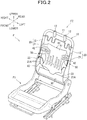
FIG. 2 is a perspective view of a seat frame embedded in the car seat. -
FIG. 3 is a front view of a seat back frame constituting the seat frame. -
FIG. 4 includes a perspective view (a) illustrating a connecting structure by which a side frame of a seat back and a lower connecting wire are connected, and a sectional view (b) taken along the line X-X of (a). -
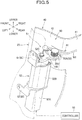
FIG. 5 is a perspective view of a driving mechanism as viewed from the rear side. -
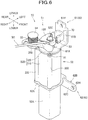
FIG. 6 is a perspective view of the driving mechanism as viewed from the front side. -
FIG. 7 is an exploded perspective view of the driving mechanism. -
FIG. 8 includes a side view (a) of a driving source, and a sectional view (b) taken along the line Y-Y of (a). -
FIG. 9 is an enlarged top view of the driving mechanism. -
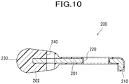
FIG. 10 is a sectional view of a contact link member. -
FIG. 11 includes explanatory views (a) to (c) for explaining the operation of the driving mechanism when the car turns to the right. -
FIG. 12 includes explanatory views (a) and (b) for explaining the operations of the driving mechanism and the pressure-receiving member when the car turns to the right. -
FIG. 13 is a view illustrating the pressure-receiving member when the car turns to the right and the driving mechanism is positioned in an advanced position. -
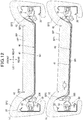
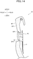
FIG. 14 is a view illustrating the positional relation in the vertical direction between a seat back pad and a support portion. -
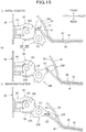
FIG. 15 includes explanatory view (a) to (c) for explaining the operation of the driving mechanism in a rear-end collision. -
FIG. 16 includes explanatory views (a) to (c) for explaining the operations of the driving mechanism and the pressure-receiving member in the rear-end collision. -
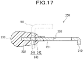
FIG. 17 is a sectional view of the contact link member according to a modified embodiment. -
FIG. 18 shows a first modification and includes a top view (a) illustrating a cover member, the contact link member, and an upper connecting wire, and a sectional view (b) thereof. -
FIG. 19 shows a second modification and is a sectional view illustrating the positional relation between the contact link member, the pressure-receiving member, and the side frame. -
FIG. 20 shows a third modification and is a sectional view illustrating the upper connecting wire and the pressure-receiving member. -
FIG. 21 shows a fourth modification and is a view illustrating the positional relation between the driving source and a torsion spring. -
FIG. 22 shows a fifth modification and includes a front view (a) illustrating the pressure-receiving member and the seat back frame and a sectional view (b) of the pressure-receiving member. -
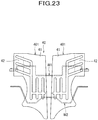
FIG. 23 shows a sixth modification and is a front view of the pressure-receiving member. -
FIG. 24 shows a seventh modification and includes a side view (a) illustrating the seat back frame and a front view (b) illustrating the pressure-receiving member and the seat back frame. -
FIG. 25 shows an eighth modification and includes a front view illustrating the pressure-receiving member and the seat back frame. -
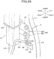
FIG. 26 shows a ninth modification and is a perspective view illustrating the side frame, the second bracket, and the driving source. -
FIG. 27 shows a tenth modification and includes a perspective view (a) illustrating the side frame and the driving source and a sectional view (b) of the left end portion of the seat back. - One embodiment of the present invention will be described in detail with reference made to the drawings, where necessary.
- As seen in
FIG. 1 , a vehicle seat according to this embodiment is configured as a car seat S used for a driver's seat and the like of an automobile, and mainly includes a seat cushion S1, a seat back S2, and a headrest S3. - A seat frame F shown in
FIG. 2 as an example of a frame is embedded in the seat cushion S1 and the seat back S2. The seat frame F mainly includes a seat cushion frame F1 constituting a frame of the seat cushion S1, and a seat back frame F2 constituting a frame of the seat back S2. The seat cushion S1 is configured such that the seat cushion frame F1 is covered with a cushion material made of urethane foam or the like, and an outer skin material made of synthetic leather or fabric. The seat back S2 is configured such that the seat back frame F2 is covered with a seat back pad BP made of a cushion material such as urethane foam (seeFIG. 12 (a) ) and an outer skin material. - The seat back frame F2 mainly includes an
upper frame 10, right and left side frames 20 constituting right and left frames of the seat back S2, and alower frame 30; theupper frame 10, the right and left side frames 20, and thelower frame 30 are joined together, for example, by welding to thereby form a frame-like configuration. - The
upper frame 10 is formed by bending a pipe material into a substantially U-shape configuration and includes alateral pipe portion 11 extending in the lateral (right-left) direction, and a pair ofsupport brackets 12 for attachment of the headrest S3 are fixed by welding to thelateral pipe portion 11. Right and leftvertical pipe portions 13 of theupper frame 10 extend in the upper-lower direction; right and left side framemain body portions 21 are joined to lower portions of thevertical pipe portions 13 by welding or the like and made into integral parts to thereby form right and left side frames 20. - Right and left side frame
main body portions 21 are arranged laterally opposite to each other. Each of the right and left side framemain body portion 21 is made by press working sheet metal to have an approximately U-shaped cross section having a pair of front and rearbent portions 21A; the front and rearbent portions 21A are formed by laterally inwardly bending both end portions of the side framemain body portion 21 located at both ends in the front-rear direction that is the width direction of the side framemain body portion 21. Each of the side framemain body portions 21 is connected to the correspondingvertical pipe portion 13 with its upper portion holding thevertical pipe portion 13, and the lower portion of the side framemain body portion 21 protrudes frontward farther than the upper portion of the side framemain body portion 21 to provide a bulgingportion 22. - As seen in
FIG. 3 , a pressure-receivingmember 40 as an example of a movable member and a pair of right and left drivingmechanisms 50 are disposed between the right and left side frames 20. Further, a controller 80 (seeFIG. 5 ) for controlling the driving mechanisms 50 (driving sources 52) is provided inside or outside the car seat S. - The pressure-receiving
member 40 is a member for receiving a load from an occupant seated on the car seat S through the outer skin material and the seat back pad BP. The pressure-receivingmember 40 is made of plastic resin or the like to allow elastic deformation, and includes a pressure-receivingportion 41 disposed to face the back of the occupant, and right and leftsupport portions 42 extending obliquely frontward toward laterally outside directions from upper portions of both right and left ends of the pressure-receivingportion 41; the pressure-receivingportion 41 and the right and leftsupport portions 42 are integrally formed with each other. The pressure-receivingmember 40 includes afirst portion 40A composed of a lower portion of the pressure-receivingportion 41 and configured to support the lumbar region of the occupant, asecond portion 40B composed of an upper portion of the pressure-receivingportion 41 and the right and leftsupport portions 42 and configured to support the occupant at a position above thefirst portion 40A, and athird portion 40C composed of a middle portion located in the middle of the pressure-receivingportion 41 in the upper-lower direction and configured to connect thefirst portion 40A and thesecond portion 40B. - The
third portion 40C is provided at a laterally center portion of the pressure-receivingmember 40. The lateral width of thethird portion 40C is smaller than that of thefirst portion 40A and that of thesecond portion 40B. In other words, the pressure-receivingmember 40 is shaped such that the middle portion thereof in the upper-lower direction is narrowed at thethird portion 40C. - The lateral width of the
first portion 40A is larger than that of thethird portion 40C. Widening the lateral width of thefirst portion 40A makes it possible to stably support the lumbar region of the occupant by thefirst portion 40A. - The pressure-receiving
member 40 is configured such that the pressure-receivingportion 41 has a first bead B1 protruding rearward and each of thesupport portions 42 has second beads B2 protruding rearward. Providing the beads B1, B2 on the pressure-receivingmember 40 makes it possible to enhance the rigidity of the pressure-receivingmember 40. - The first bead B1 is shaped to recess as viewed from the front side. The first bead B1 consists of a plurality of vertical bead portions B11 extending in the upper-lower direction on the
third portion 40C, and a connecting bead portion B12 extending laterally to connect the plurality of vertical bead portions B11. Each of the vertical bead portions B11 extends from thesecond portion 40B to thefirst portion 40A via thethird portion 40C. The laterally outermost vertical bead portions B11 extend into thesecond portion 40B, and upper end portions thereof are arranged at an upper portion of thesecond portion 40B. - The second beads B2 are shaped to recess as viewed from the front side. The second beads B2 are formed at a plurality of locations and spaced apart from each other in the upper-lower direction; the second beads B2 extend from laterally outer end portions of the
support portions 42 toward the first bead B1 and are connected to the laterally outermost vertical bead portions B11. This configuration makes it possible to enhance the rigidity at the boundary (portions bent along the illustrated line) between the pressure-receivingportion 41 and thesupport portions 42. - The second beads B2 extend diagonally relative to the horizontal plane. To be more specific, the second beads B2 extend obliquely from the first bead B1 in laterally outward and upward directions.
- Further, at each boundary located between the pressure-receiving
portion 41 and thesupport portion 42, arelief portion 44 having a recessed rear surface is formed in a position corresponding to an upper connecting wire W1 which will be described later (see alsoFIG. 5 ). In this embodiment, therelief portion 44 is located in a position overlapping the second bead B2 that is provided in the middle portion in the upper-lower direction. - The pressure-receiving
member 40 is connected in such a manner as to be movable in the front-rear direction relative to the right and left side frames 20 via upper and lower connecting wires W1, W2 as an example of elastic members. - The upper connecting wire W1 extends at the rear side of the pressure-receiving
member 40 from onesupport portion 42 to theother support portion 42. Namely, the upper connecting wire W1 is provided to hold thesecond portion 40B from the rear side between right and left end portions of thesecond portion 40B. Further, the upper connecting wire W1 is bent such that a laterally center portion thereof protrudes downward. To be more specific, the upper connecting wire W1 is provided corresponding to the upper portion of the pressure-receivingportion 41, and includes a downwardly-protruding U-shaped bent portion W11, and side portions W12 extending laterally outward from right and left ends of the bent portion W11. The lower portion of the bent portion W11 is positioned lower than the contact position (relief portion 44) at which the upper connecting wire W1 contacts the pressure-receivingmember 40, more specifically, positioned substantially at the same height as the lower end of thesupport portion 42. End portions of the upper connecting wire W1 are connected to the drivingmechanisms 50 fixed to the side frames 20 respectively, and by engaging engagement hooks (not shown) formed on an upper portion of the rear surface of the pressure-receivingmember 40 with the upper connecting wire W1, the upper portion of the pressure-receivingmember 40 is connected to the right and left side frames 20. - End portions of the lower connecting wire W2 are connected to wire attachment portions 23 (see
FIG. 4 ) which are provided on the side frames 20 respectively, and by engaging engagement hooks (not shown) formed on a lower portion of the rear surface of the pressure-receivingmember 40 with the lower connecting wire W2, the lower portion of the pressure-receivingmember 40 is connected to the right and left side frames 20. - As seen in
FIGS. 4 (a) and (b) , thewire attachment portion 23 is formed by bending sheet metal or the like, and afixing piece 23A thereof is fixed to a laterally inner surface of the side framemain body portion 21 by welding, a screw, or the like. Thewire attachment portion 23 includes the fixingpiece 23A, a connectingpiece 23B extending laterally inward from an upper end portion of the fixingpiece 23A, and anengagement piece 23C extending upward from a laterally inner end portion of the connectingpiece 23B. Anoblong hole 23D extending long in the front-rear direction and approximately in the shape of an oval is formed in theengagement piece 23C, and by engaging the end portion of the lower connecting wire W2 into theoblong hole 23D, the lower connecting wire W2 is connected to theside frame 20. Further, aplastic spacer 23E is engaged into theoblong hole 23D at the front of the lower connecting wire W2 to thereby prevent the lower connecting wire W2 from moving frontward and rearward within theoblong hole 23D. - As seen in
FIG. 12 (a) , the seat back pad BP includes a central pad portion BP1 disposed to face the pressure-receivingportion 41, and right and left side pad portions BP2 provided at both right and left sides of the central pad portion BP1 and configured to protrude frontward farther than the central pad portion BP1. - The side pad portion BP2 extends laterally outward from the central pad portion BP1 along the
support portion 42 of the pressure-receivingmember 40, and then extends rearward along the laterally outer side of theside frame 20, and finally extends laterally inward at the rear side of theside frame 20. The side pad portion BP2 has a space formed between thesupport portion 42 of the pressure-receivingmember 40 and theside frame 20, so that thedriving mechanism 50 disposed in this space is prevented from contacting the seat back pad BP. - A first tuck-in groove BP3 is provided between the central pad portion BP1 and each of the side pad portions BP2. The first tuck-in groove BP3 is a groove that is recessed as viewed from the front side and extends in the upper-lower direction. Provided at a bottom portion of the first tuck-in groove BP3 are outer skin attachment members (not shown) disposed vertically for allowing the outer skin material of the seat back S2 to be tucked in the first tuck-in groove BP3. As viewed from the front-rear direction, the first tuck-in grooves BP3 are provided at positions overlapping the right and left end portions of the pressure-receiving
member 40. Namely, the pressure-receivingmember 40 extends laterally outward from the inner region to the outer region of the first tuck-in grooves BP3, and thesupport portions 42 are located laterally outside the first tuck-in grooves BP3. - Further, as seen in
FIG. 14 , a pair of second tuck-in grooves BP4 are provided in the central pad portion BP1 approximately at a center portion thereof in the upper-lower direction. Each second tuck-in groove BP4 is a groove that is recessed as viewed from the front side and extends in the right-left direction (lateral direction). Provided at a bottom portion of the second tuck-in groove BP4 are outer skin attachment members (not shown) disposed laterally for allowing the outer skin material of the seat back S2 to be tucked in the second tuck-in groove BP4. The pair of second tuck-in grooves BP4 are provided at positions above and below thesupport portions 42, respectively, of the pressure-receivingmember 40. Namely, thesupport portions 42 and the upper connecting wire W1 are provided at the same height position as that of the region between the pair of second tuck-in grooves BP4. According to this embodiment, theentire support portions 42 are provided at the same height as the region between the pair of second tuck-in grooves BP4; however, thesupport portions 42 may be provided such that only part thereof is positioned at the same height as the region between the pair of second tuck-in grooves BP4. - As seen in
FIG. 3 , thedriving mechanism 50 is a mechanism for actuating the pressure-receivingmember 40, and is provided at each of the right and left side frames and arranged on both right and left sides of the pressure-receivingmember 40. Although details thereof will be described later, thedriving mechanism 50 is configured to move the right end portion or the left end portion of the pressure-receivingmember 40 from an initial position as shown inFIG. 12 (a) to an advanced position that is located frontward of the initial position as shown inFIG. 13 to orient the pressure-receivingmember 40 to the right or to the left, or to move (return) the same from the advanced portion to the initial position. Further, the driving mechanism 50 (linkage 51) is configured to operate when a load equal to or greater than a predetermined amount is input from an occupant to the pressure-receivingmember 40 to cause the pressure-receivingmember 40, to move to a backward position as shown inFIG. 16 (c) that is located rearward of an initial position of the pressure-receivingmember 40 as shown inFIG. 16 (a) . - As seen in
FIG. 5 , thedriving mechanism 50 mainly includes alinkage 51 connected to the pressure-receivingmember 40 via the upper connecting wire W1, and a drivingsource 52 configured to actuate thelinkage 51. The right and left drivingmechanisms 50 are substantially symmetrical in structure, and the left-side driving mechanism 50 will be mainly explained in detail in the following description with reference to the drawings. - As seen in
FIGS. 6 and7 , the drivingsource 52 mainly includes amotor 52A, agearbox 52B, and anoutput shaft 52C; the drivingsource 52 is fixed to theside frame 20 via abracket 60. The drivingsource 52 is disposed in such a position as not to get in contact with the pressure-receivingmember 40. - The
motor 52A is configured such that widths thereof in the lateral direction as well as in the front-rear direction are smaller than those of thegearbox 52B that is disposed on an upper portion of themotor 52A. Namely, the drivingsource 52 is narrower at its lower portion (motor 52A) than at its upper portion (gearbox 52B). - The
gearbox 52B is a member for accommodating a train of gears (not shown) configured to reduce a speed with which a rotary driving force generated by themotor 52A is transmitted therethrough, and mainly includes abox body 310 approximately in the shape of a tube, and alid member 320 configured to close an upper end portion (at an end portion in the axial direction of theoutput shaft 52C) of thebox body 310. Provided at side surfaces of thebox body 310 and thelid member 320 are three fasteningportions 330 each protruding radially outward of theoutput shaft 52C. Thefastening portion 330 is a portion in which ascrew 91 as an example of a fastening member for fastening thebox body 310 and thelid member 320 is disposed. Thefastening portions 330 are arranged on the side surface of thegearbox 52B at equally-spaced intervals in a circumferential direction of thegearbox 52B. - The
output shaft 52C is a shaft for outputting the rotary driving force of themotor 52A, the speed of which has been reduced by thegearbox 52B. Theoutput shaft 52C is disposed through thelid member 320. - The structure of the
bracket 60 by which the driving source 52 (driving mechanism 50) is fixed to theside frame 20 will be described. - The
bracket 60 consists of afirst bracket 61 and asecond bracket 62. Each of thefirst bracket 61 and thesecond bracket 62 is made by press working sheet metal to have an approximately L-shaped cross section, and mainly includes anengagement portion portion - The
engagement portion 61A of thefirst bracket 61 is a portion engaged with an upper end portion (lid member 320) of thegearbox 52B that is a portion of the drivingsource 52 located at one end in the axial direction thereof; theengagement portion 61A is approximately in the shape of a circular disk having an engagement hole. The fixingportion 61B is a portion fixed to theside frame 20, and extends along theside frame 20 from a laterally outer end portion (end portion located near the side frame 20) of theengagement portion 61A toward an upper side opposite to a lower side on which a portion of the drivingsource 52 located at the other end in the axial direction thereof (opposite to the one end) is located. The fixingportion 61B has acircular hole 61H through which abolt 92 for fixing thefirst bracket 61 to theside frame 20 is inserted. - The
engagement portion 62A of thesecond bracket 62 is a portion engaged with themotor 52A of the drivingsource 52, and is approximately in the shape of a frame. The fixingportion 62B is a portion fixed to theside frame 20, and extends downward along theside frame 20 from a laterally outer end portion of theengagement portion 62A. As seen inFIG. 8 (a) , the fixingportion 62B has anextension portion 62C extending frontward (in a direction orthogonal to the axial direction) farther than the drivingsource 52 when viewing theside frame 20 laterally from the inner side. Theextension portion 62C has acircular hole 62H (seeFIG. 7 ) through which abolt 93 for fixing thesecond bracket 62 to theside frame 20 is inserted. - As seen in
FIG. 7 , thefirst bracket 61 is fixed to the drivingsource 52 with theengagement portion 61A being engaged with the upper end portion of thegearbox 52B and fastened to thegearbox 52B by three bolts 94 (only one of them is shown in the figure), whereas thesecond bracket 62 is fixed to the drivingsource 52 with theengagement portion 62A being engaged with themotor 52A and fastened to thegearbox 52B by three screws 95 (only one of them is shown in the figure). Further, as seen inFIG. 8 (a) , the drivingsource 52 is fixed to theside frame 20 with the fixingportion 61B being fixed to theside frame 20 by abolt 92 and with the fixingportion 62B being fixed at itsextension portion 62C to theside frame 20 by abolt 93. - In this embodiment, when viewing the
side frame 20 shown inFIG. 8 (a) from a side where the drivingsource 52 is fixed to theside frame 20, the fixingportion 61B and theextension portion 62C do not overlap the driving source 52 (extend outward beyond the driving source 52), so that thebracket 60 can be easily attached to theside frame 20 by thebolts source 52 can be easily fixed to theside frame 20. Further, the drivingsource 52 can be stably fixed to theside frame 20 by means of the two brackets, i.e., thefirst bracket 61 and thesecond bracket 62. - The
extension portion 62C has a front end portion disposed on the bulgingportion 22 of theside frame 20. This configuration makes it unnecessary to provide theside frame 20 with a dedicated portion on which theextension portion 62C extending frontward beyond the drivingsource 52 is disposed, so that the structure of theside frame 20 can be simplified and a compact structure can be provided around the drivingsource 52. - As seen in
FIG. 8 (b) , the drivingsource 52 fixed to theside frame 20 via thebracket 60 is located such that as viewed from an axial direction of theoutput shaft 52C, all the threefastening portions 330 are arranged at positions avoiding a line LN (shown by the alternate long and short dash line) connecting the ends of the pair ofbent portions 21A of theside frame 20. To be more specific, as viewed from the axial direction, thefastening portions 330 are provided such that at least onefastening portion 330 is arranged on each side of the line LN, and more specifically, one at a laterally outer side of the line LN and two at a laterally inner side of the line LN. - The first bracket 61 (
engagement portion 61A) has a size such that as viewed from the axial direction, the laterallyinner end 61E thereof does not protrude laterally inward from the laterallyinner end 52E of the drivingsource 52. With this configuration, thefirst bracket 61 does not protrude on an occupant's side, so that a compact structure can be provided around the drivingsource 52. - As shown in
FIG. 7 , thelinkage 51 is rotatable substantially in the front-rear direction relative to theside frame 20, and mainly includes two links for actuating the pressure-receivingmember 40, more specifically, adrive link member 100 as an example of a second link member and acontact link member 200 as an example of a link member. - The
drive link member 100 is a member made of metal and in the shape of a long plate, and mainly includes ashaft hole 110 formed in one end portion thereof, a pin-insertion hole 120 formed in the other end portion thereof, and astopper portion 130. Thedrive link member 100 is fastened to the drivingsource 52 with theshaft hole 110 being connected to (e.g., serration-fitted onto) theoutput shaft 52C of the drivingsource 52 and theoutput shaft 52C being clipped by an E-ring 53 to prevent thedrive link member 100 from coming off theoutput shaft 52C. With this configuration, thedrive link member 100 rotates substantially in the front-rear direction when the drivingsource 52 is driven. - The
stopper portion 130 is a portion configured to contact a member fixed to theside frame 20, specifically a fixedstopper member 70 to be described later, to restrict a rotation of thedrive link member 100 itself. To be more specific, thestopper portion 130 includes afirst stopper portion 131 configured to restrict a rotation of thedrive link member 100 in a forward direction (in one direction) and asecond stopper portion 132 configured to restrict a rotation of thedrive link member 100 in a rearward direction (in a direction opposite to the one direction). - As seen in
FIG. 9 , thefirst stopper portion 131 and thesecond stopper portion 132 are provided, as viewed from a direction of the axis of rotation of the drive link member 100 (axial direction of theoutput shaft 52C), at an outer peripheral portion of thedrive link member 100, in other words, at a contour portion of thedrive link member 100. Furthermore, thefirst stopper portion 131 and thesecond stopper portion 132 are provided on aside surface 102 which surrounds theoutput shaft 52C that is an axis of rotation of thedrive link member 100. To be more specific, thefirst stopper portion 131 protrudes substantially frontward from the front side of the longmain body portion 101 when thedrive link member 100 takes a posture shown inFIG. 9 (i.e., when the pressure-receivingmember 40 is in an initial position); that surface of thefirst stopper portion 131 which contacts the fixedstopper member 70 is substantially flat. Further, in this posture of thedrive link member 100, thesecond stopper portion 132 protrudes substantially leftward from the rear side of themain body portion 101; that surface of thesecond stopper portion 132 which contacts the fixedstopper member 70 is substantially flat. - The structure of the fixed
stopper member 70 will be described. - The fixed
stopper member 70 is a member for restricting a rotation of thedrive link member 100 by thestopper portion 130 coming into contact with the fixedstopper member 70; the fixedstopper member 70 is fixed to theside frame 20. To be more specific, the fixedstopper member 70 is disposed between theoutput shaft 52C and theside frame 20; as viewed form the axial direction of theoutput shaft 52C, the fixedstopper member 70 has the shape of the letter U opening toward the laterally inner side that is a side where thedrive link member 100 is disposed. The fixedstopper member 70 is fixed to theside frame 20 via thefirst bracket 61 with aproximal portion 72 of the fixed stopper member 70 (that is located opposite to endportions 71 of the letter U) being fixed to thefirst bracket 61 by welding or the like. - The fixed
stopper member 70 has a rotation-restrictingportion 73 at each of itsend portions 71 such that the stopper portion of thedrive link member 100 can come into contact with the rotation-restrictingportions 73. Each rotation-restrictingportion 73 is approximately in the shape of a rectangular tube and engageable onto theend portion 71; the rotation-restrictingportion 73 is made of plastic resin. Thedrive link member 100 is configured such that a frontward rotation thereof (i.e., rotation of thedrive link member 100 toward the front side) is restricted with thefirst stopper portion 131 coming into contact with the front-side rotation-restricting portion 73 (seeFIG. 11 (c) ), whereas a rearward rotation thereof (i.e., rotation of thedrive link member 100 toward the rear side) is restricted with thesecond stopper 132 coming into contact with the rear-side rotation-restrictingportion 73. Since the rotation-restrictingportions 73 are made of plastic resin, contact noise generated between thestopper portion 130 and the fixedstopper member 70 can be suppressed, so that noise produced by the actuation of thedrive link member 100 can be suppressed. - Further, as viewed from the axial direction of the
output shaft 52C, each of the rotation-restrictingportions 73 is located within a generally circular-shaped contour of the drivingsource 52. This makes it possible to suppress upsizing of thedrive link member 100 having theside surface 102 on which is provided thestopper portion 130 contactable with the rotation-restrictingportions 73, so that a compact structure of thedrive link member 100 can be provided. - As viewed from the axial direction, the
output shaft 52C is so disposed as to face anopening 74 of the U-shaped fixedstopper member 70. This makes it possible to arrange thedrive link member 100 and the fixedstopper member 70 laterally adjacent to each other, so that a compact structure can be provided around thedrive link member 100. - Further, as viewed from the axial direction of the
output shaft 52C, thestopper portion 130 is disposed inside a circle C (shown by the alternate long and short dash line); the circle C is defined such that the center of the circle C coincides with the rotation center C1 of thedrive link member 100 and the radius of the circle C corresponds to the distance from the rotation center C1 to the rotation center C2 of thecontact link member 200. With this configuration, upsizing of thedrive link member 100 can be suppressed and a compact structure of thedrive link member 100 can be provided. - In this embodiment, the right and left
drive link members 100 are each provided using a common part. To be more specific, thedrive link member 100 constituting the left-side driving mechanism 50 shown inFIG. 9 can be used as the right-side driving mechanism 50 by reversing it or placing the reverse side obverse. This configuration is achieved because thestopper portion 130 is provided on theside surface 102 of the plate-likedrive link member 100 but does not protrude only in one side in the axial direction. Using the common part makes it possible to reduce the number of parts and to save the effort of parts management, so that reduction in the cost can be achieved. Further, the mix-up between the right and left parts can be prevented and the assembling is facilitated. - As seen in
FIG. 7 , thecontact link member 200 is a member in the shape of a long plate, and mainly includes astopper 210 and a pin-insertion hole 220 formed in one end portion thereof, acontact portion 230 provided on the other end portion thereof, and a through-hole 240 formed in a region between the pin-insertion hole 220 and thecontact portion 230. Thecontact link member 200 rotates substantially in the front-rear direction relative to thedrive link member 100 with thepin 54 being engaged into the pin-insertion hole 220 and the pin-insertion hole 120 of thedrive link member 100. Further, thecontact link member 200 is connected to the pressure-receivingmember 40 via the upper connecting wire W1 with an end portion of the upper connecting wire W1 being inserted into the through-hole 240. - The
contact portion 230 is a portion configured to contact the pressure-receivingmember 40 when the drivingsource 52 actuates the pressure-receivingmember 40. As seen inFIG. 9 , thecontact portion 230 has a convexly curved shape as viewed from a direction of the axis of rotation of thecontact link member 200. Further, as seen inFIG. 10 , thecontact portion 230 also has a convexly curved shape as viewed from any direction orthogonal to the direction of the axis of rotation. To be more specific, thecontact portion 230 is approximately spherical in shape. - When the pressure-receiving
member 40 is in the initial position (as shown by the solid line inFIG. 9 ) and a load is not input from an occupant to the pressure-receiving member 40 (i.e., when an occupant is not seated on the car seat S), the pressure-receivingmember 40 is spaced apart from thecontact portion 230. When an occupant sits on the car seat S and a load is input from the occupant to the pressure-receivingmember 40 in the initial position, thesupport portion 42 deforms as shown by the chain double-dashed line and contacts thecontact portion 230. With this configuration, since deformation or movement of the pressure-receivingmember 40 is allowed until the pressure-receivingmember 40 comes into contact with thecontact portion 230, the cushionability of the seat back S2 can be improved. The pressure-receivingmember 40 has acontact surface 43, with which thecontact portion 230 comes into contact, at the rear surface of thesupport portion 42. As viewed from the direction of the axis of rotation of thecontact link member 200, thecontact surface 43 has a concavely curved shape. - Further, because of the provision of the
relief portion 44, thesupport portion 42 has, at the same height position as the height of the position of the upper connecting wire W1, afirst support portion 45 extending in a diagonally leftward and frontward direction from the pressure-receivingportion 41, and asecond support portion 46 extending further in a diagonally leftward and frontward direction from a laterally outward end portion of thefirst support portion 45. Thecontact surface 43 is provided on thesecond support portion 46. The upper connecting wire W1 is bent at a portion corresponding to a boundary between the pressure-receivingportion 41 and thefirst support portion 45, and contiguously in contact with the pressure-receivingportion 41 and thefirst support portion 45. - The
contact portion 230 of thecontact link member 200 is provided, as seen inFIGS. 12 (a) and (b) , so as to contact thecontact surface 43 of the pressure-receivingmember 40 at a position laterally outward of the tuck-in groove BP3 of the seat back pad BP. The seat back pad BP is thinner at a potion where the tuck-in groove BP3 is formed, and is easily deformable at this thinner portion. With this configuration, when thecontact portion 230 pushes thesupport portion 42 of the pressure-receivingmember 40 forward, the side pad portion BP2 of the seat back pad BP can be pushed forward with a small force. - Retuning to
FIG. 9 , thestopper 210 is a portion configured to contact theside surface 102 of thedrive link member 100 to restrict the amount of rearward rotation of the contact link member 200 (seeFIG. 11 (c) andFIG. 15 (c) ). Thestopper 210 protrudes out from one end portion of thecontact link member 200 and is bent downward at the distal end of this protruding portion toward the lower side where thedrive link member 100 is disposed. - As seen in
FIG. 10 , thecontact link member 200 includes alink body 201 having the shape of a long plate, and acover member 202 entirely covering thelink body 201. Thelink body 201 and thecover member 202 are made of different materials. To be more specific, thecontact link member 200 is made by insert molding or the like; thelink body 201 is made of metal and thecover member 202 is made of plastic resin. The through-hole 240 is formed through thelink body 201 and thecover member 202. Thecontact portion 230 is provided on thecover member 202 and formed as a part of thecover member 202. Accordingly, thecontact portion 230 is made of plastic resin. - As seen in
FIG. 9 , thecontact link member 200 is formed such that the length from the rotation center C2 thereof to thecontact portion 230 is longer than the length from the rotation center C2 to the rotation center C1 of thedrive link member 100. - As seen in
FIGS. 6 and7 , atorsion spring 55 as an urging member is disposed between (in terms of its mechanics between) thedrive link member 100 and thecontact link member 200. Thetorsion spring 55 is a member configured to urge thecontact link member 200 to rotate frontward (in one direction), and includes acoil portion 55A disposed on the contact link member 200 (i.e., on the opposite side of thecontact link member 200 from the drivingsource 52, afirst arm portion 55B extending radially outward from an upper end of thecoil portion 55A and bent downward at its distal end to provide an approximately L-shaped configuration, and asecond arm portion 55C extending radially outward from a lower end of thecoil portion 55A and bent downward at its distal end to provide an L-shaped configuration. - The
torsion spring 55 is positioned with thecoil portion 55A thereof being engaged by thepin 54, with thefirst arm portion 55B as one end of thetorsion spring 55 being hooked onto thefirst stopper portion 131 of thedrive link member 100, and with thesecond arm portion 55C as the other end of thetorsion spring 55 being hooked onto thestopper 210 of thecontact link member 200. With this configuration, thetorsion spring 55 generates an urging force to rotate thecontact link member 200 in a direction shown by the arrow inFIG. 9 . - The
torsion spring 55 and the upper connecting wire W1 as an example of a connecting wire serve as a member for restricting a rearward rotation of thecontact link member 200, in other words, a member (rotation resistive member) to provide resistance against the rearward rotation. To be more specific, thetorsion spring 55 urges thecontact link member 200 to rotate frontward, to thereby restrict a rearward rotation of thecontact link member 200. - Further, the upper connecting wire W1 has right and left end portions, both of which are bent diagonally frontward, and a downwardly extending end portion of each end portion is coupled into the through-opening 240 of the
contact link member 200, so that the upper connecting wire W1 connects the pressure-receivingmember 40 and thecontact link member 200. Further, a connecting portion C3 connecting thecontact link member 200 and the pressure-receivingmember 40 is located, when the pressure-receivingmember 40 is in the initial position shown inFIG. 9 , at a front end portion of thecontact link member 200, more specifically, at a position frontward of the rotation center C2 of thecontact link member 200, so that the upper connecting wire W1 urges thecontact link member 200 to rotate frontward; this can restrict a rearward rotation of thecontact link member 200. - The
coil portion 55A of thetorsion spring 55 is so located as to face therelief portion 44 of the pressure-receiving member 40 (seeFIG. 5 ). This configuration suppresses a noise which would occur when the pressure-receivingmember 40 deforms, and can serve to make effective use of the space. - As viewed along the upper-lower direction, the
coil portion 55A of thetorsion spring 55 overlaps part of the drivingsource 52, more specifically, thefastening portion 330. This makes it possible to downsize thedriving mechanism 50 in the horizontal direction. Further, thecoil portion 55A is spaced apart from the upper connecting wire W1. This arrangement can reduce the possibility of undesired engagement of the upper connecting wire W1 with thecoil portion 55A when the upper connecting wire moves backward. - When the pressure-receiving
member 40 is in the initial position as shown inFIG. 9 , the connecting portion C3 is located inside the circle C shown by the alternate long and short dash line, as viewed from the direction of the axis of rotation of thecontact link member 200. Further, the connecting portion C3 is located laterally outward of the rotation center C2 of thecontact link member 200 when the pressure-receivingmember 40 is in the initial position. - The driving
mechanisms 50 configured as described above are independently operable at the right-side and at the left-side. To be more specific, the drivingsources 52 are controlled by thecontroller 80 so that the right-side driving source 52 and the left-side driving source 52 are independently driven, and thedrive link member 100 and thecontact link member 200 of the right-side linkage 51 and thedrive link member 100 and thecontact link member 200 of the left-side linkage 51 are independently rotatable. Namely, the drivingmechanisms 50 are not configured such that, for example, when the left-sidedrive link member 100 and the left-sidecontact link member 200 rotate, the right-sidedrive link member 100 and the right-sidecontact link member 200 rotate in an interlocking manner. - As seen in
FIG. 5 , thecontroller 80 is configured to control the actuation of each driving source 52 (motor 52A) so that the pressure-receivingmember 40 disposed in the seat back S2 is oriented toward a turning direction (seeFIG. 13 ). Although various control methods are available with thecontroller 80, as an example, lateral acceleration and turning direction may be obtained based on signals from wheel speed sensors and a steering angle sensor, and if the thus obtained lateral acceleration exceeds a predetermined threshold value, then themotor 52A of thedriving mechanism 50 located at the outer side in the turning direction is driven, to thereby orient the pressure-receivingmember 40 toward the turning direction. - In this embodiment, the
controller 80 monitors electric current flowing through themotor 52A during the operation of themotor 52A, and stops the supply of electric current to themotor 52A to stop the operation of themotor 52A. When thedrive link member 100 rotates until thestopper portion 130 contacts the fixedstopper member 70, themotor 52A stops and the electric current flowing through themotor 52A becomes large. Thecontroller 80 detects this condition and stops the supply of electric current to themotor 52A. This configuration makes it possible with a simple structure to cause thestopper portion 130 to appropriately work as well as to precisely regulate the amount of rotation of thedrive link member 100. - Next, operations of the
driving mechanism 50 and the pressure-receivingmember 40 during cornering of the car will be described. - When the car turns to the right, the
controller 80 actuates the drivingsource 52 of the left-side driving mechanism 50. This causes thedrive link member 100 to rotate frontward from the posture shown inFIG. 11 (a) to the postures shown inFIGS. 11 (b) and (c) , so that thecontact link member 200 moves frontward while rotating relative to thedrive link member 100. Accordingly, the left end portion (connecting portion C3) of the upper connecting wire W1 moves frontward to thereby cause the left-side support portion 42 (left end portion) of the pressure-receivingmember 40 to move from the initial position to the advanced position that is located frontward of the initial position. - The
first stopper portion 131 of thedrive link member 100 then comes into contact with the front-side rotation-restrictingportion 73 of the fixedstopper member 70, so that the rotation of thedrive link member 100 is restricted, and thestopper 210 of thecontact link member 200 comes into contact with theside surface 102 of thedrive link member 100, so that the rotation of thecontact link member 200 is restricted. In so doing, the electric current flowing through the drivingsource 52 exceeds the predetermined value, and thecontroller 80 stops the operation of the drivingsource 52. - Accordingly, as seen in
FIGS. 12 (a), (b) and13 , the left end portion of the pressure-receivingmember 40 moves from the initial position to the advanced position, so that the entire pressure-receivingmember 40 is oriented to the turning direction, i.e., to the right-side. As a result, the centrifugal force applied to the occupant during cornering can be appropriately supported by the seat back S2. - To be more specific, as seen in
FIG. 3 , when thesupport portion 42 of the pressure-receivingmember 40 moves from the initial position to the advanced position, the lower portion of the pressure-receivingportion 41, that is, thefirst portion 40A does not move in the front-rear direction because thefirst portion 40A is supported by the lower connecting wire W2 that is fixed to the side frames 20 (and does not move at least by the operation of the driving mechanism 50). This causes the pressure-receivingmember 40 to get twisted at thethird portion 40C that is located between thefirst portion 40A and thesecond portion 40B having thesupport portions 42. In this embodiment, since the lateral width of thethird portion 40C is smaller than that of thefirst portion 40A and that of thesecond portion 40B, the pressure-receivingmember 40 easily gets twisted at thethird portion 40C. With this configuration, thesupport portions 42 can move smoothly between the initial position and the advanced position. - It is to be noted that since the first bead B1 is provided on the
third portion 40C, a plastic deformation of the pressure-receivingmember 40 can be suppressed when it is twisted. Further, the first bead B1 extends in the upper-lower direction, which does not prevent the pressure-receivingmember 40 from being twisted at thethird portion 40C. - Further, the
first portion 40A and thesecond portion 40B are connected at thethird portion 40C, so that an uncomfortable feeling experienced by the occupant when thesupport portions 42 move can be suppressed, as compared with an alternative configuration in which thefirst portion 40A and thesecond portion 40B are not connected. - In this embodiment, since the
linkage 51 consists of thedrive link member 100 and thecontact link member 200, when comparing with an alternative configuration in which the upper connecting wire W1 is directly connected to one link member (e.g., drivelink member 100 shown inFIG. 11 ) to move the pressure-receivingmember 40 in the front-rear direction, a long travel distance of the left end portion of the upper connecting wire W1 in the front-rear direction can be ensured. This makes it possible to ensure a sufficient travel distance (amount of inclination) of the pressure-receivingmember 40, so that the centrifugal force applied to the occupant during cornering can be favorably supported by the pressure-receivingmember 40. - Further, in this embodiment, when the pressure-receiving
member 40 is in the initial position, the connecting portion C3 is located laterally outward of the rotation center C2 and thecontact link member 200 is urged to rotate frontward by the upper connecting wire W1 and other parts, so that thecontact link member 200 is unlikely to rotate rearward. This configuration can prevent the distal end of thecontact link member 200 from unsteadily moving when the pressure-receivingmember 40 is moved from the initial position to the advanced position, so that a stable movement of the pressure-receivingmember 40 can be ensured. - In this embodiment, as seen in
FIG. 11 (c) , thecontact link member 200 in the advanced position takes a posture such that the laterallyouter end portion 231 of thecontact portion 230 is located laterally outward of thelateral end 49 of thesupport portion 42 of the pressure-receivingmember 40. With this arrangement, thecontact link member 200 supports the end portion of thesupport portion 42 of the pressure-receivingmember 40, so that the pressure-receivingmember 40 can be stably supported by thecontact link member 200. - Further, in the advanced position, the connecting portion C3 connecting the
contact link member 200 and the upper connecting wire W1 is located laterally outward of a first imaginary line L1 connecting the contact point P of thecontact portion 230 and the pressure-receivingmember 40 and the rotation center C2 of thecontact link member 200. With this arrangement, thecontact link member 200 can support the pressure-receivingmember 40 at a position as laterally outward as possible, so that the pressure-receivingmember 40 can be stably supported by thecontact link member 200. - Further, in the advanced position, the rotation center C2 of the
contact link member 200 is located laterally inward of a second imaginary line L2 connecting the contact point P of thecontact portion 230 and the pressure-receivingmember 40 and the shaft center C4 (rotation center of the drive link member 100) of the drivingsource 52. This arrangement can suppress an excessive rotation of thecontact link member 200 in the clockwise direction ofFIG. 11 when a load is applied in the advanced position from the occupant to the left-side support portion 42 of the pressure-receivingmember 40. - In this embodiment, as seen in
FIG. 13 , thecontact link member 200 rotates to such an extent that in the advanced position, the contact point P of thecontact link member 200 and the pressure-receivingmember 40 is located frontward farther than the front end of theside frame 20. With this configuration, sufficient amount of frontward displacement of thecontact link member 200 can be ensured. - As seen in
FIGS. 12 and13 , thedriving mechanism 50 is disposed in a space of the seat back pad BP formed between the pressure-receivingmember 40 and theside frame 20 and is configured such that thecontact link member 200 does not contact the seat back pad BP even when thecontact link member 200 rotates. This configuration can suppress abnormal noise which would occur when thecontact link member 200 contacts the seat back pad BP. - Further, as seen in
FIG. 14 , the seat back pad BP is thinner at a potion where the pair of second tuck-in grooves BP4 are formed and thus a portion between the pair of second tuck-in grooves BP4 is easily caused to sag. Thesupport portions 42 of the pressure-receivingmember 40 and the upper connecting wire W1 are provided at the same height as that of the portion between the pair of second tuck-in grooves BP4, so that when thesupport portions 42 and the upper connecting wire W1 are moved, the seat back pad BP is easily deformable in accordance with the movements thereof. - When the car is to be shifted from turning state to straight travelling state, the
controller 80 drives the drivingsource 52 of the left-side driving mechanism 50 to rotate in a direction reverse to that in which it rotates in the turning state. This causes thedrive link member 100 to rotate rearward from the posture shown inFIG. 11 (c) to the postures shown inFIGS. 11 (b) and (a) . Thecontact link member 200 then moves rearward while rotating relative to thedrive link member 100 by the load applied from the occupant to the pressure-receivingmember 40. This causes the left end portion of the upper connecting wire W1 to move rearward, and the left-side support portion 42 of the pressure-receivingmember 40 is moved from the advanced position to the initial position. - Further, the
second stopper portion 132 of thedrive link member 100 comes into contact with the rear-side rotation-restrictingportion 73 of the fixedstopper member 70, so that the rotation of thedrive link member 100 is restricted. In so doing, the electric current flowing through the drivingsource 52 exceeds the predetermined value, and thecontroller 80 stops the operation of the drivingsource 52. Accordingly, the pressure-receivingmember 40 returns from the posture shown inFIG. 12(c) in which the pressure-receivingmember 40 is oriented to the right to the posture shown inFIG. 12 (a) in which the pressure-receivingmember 40 faces the front. - On the other hand, when the car turns to the left, the
controller 80 actuates the drivingsource 52 of the right-side driving mechanism 50. The subsequent operations of the pressure-receivingmember 40 and the right-side driving mechanism 50 are similar to those in the right turn, and therefore detailed description thereof will be omitted. - In this embodiment, the pressure-receiving
member 40 is configured such that when an occupant sits on the car seat S and the pressure-receivingmember 40 contacts thecontact portion 230 of thecontact link member 200, thecontact surface 43 keeps on contacting thecontact portion 230 in the whole rotation range of thecontact link member 200. With this configuration, the rotation of thecontact link member 200 is guided, in a sense, by the pressure-receivingmember 40, so that thecontact link member 200 can be operated smoothly. - Further, in this embodiment, since the
contact portion 230 and the pressure-receivingmember 40 are made of plastic resin, rubbing noise generated between thecontact link member 200 and the pressure-receivingmember 40 and the abrasion thereof can be suppressed. Further, since thecontact surface 43 has a concavely curved shape and the contact pressure between thecontact portion 230 and thecontact surface 43 is lessened, abrasion of thecontact link member 200 and the pressure-receivingmember 40 can be further suppressed. - Next, operations of the
driving mechanism 50 and the pressure-receivingmember 40 in a rear-end collision will be described. Herein, the term "in the rear-end collision" indicates an occasion when the car is rear-ended by another car or when the car collides at the rear portion thereof with another car or a structural object while reversing. - As seen in
FIG. 15 (a) , in a normal condition in which the pressure-receivingmember 40 is in the initial position without occurrence of a rear-end collision (i.e., when a load smaller than the predetermined amount has been input from an occupant to the pressure-receiving member 40), a rearward rotation of thecontact link member 200 is restricted by the upper connecting wire W1 and the like, so that the pressure-receivingmember 40 does not move rearward so much from the initial position. - On the other hand, when a rear-end collision occurs and a load equal to or greater than the predetermined amount is input from the occupant to the pressure-receiving
member 40, this large load causes the pressure-receivingmember 40 to move backward, so that the end portions of the upper connecting wire W1 pull the contact link members 200 (connecting portions C3) backward. In so doing, as seen inFIG. 15 (b) , thecontact link members 200 move rearward while causing the upper connecting wire W1 and the pressure-receivingmember 40 to elastically deform laterally inward, so that the pressure-receivingmember 40 moves further backward from the initial position to the backward position shown inFIG. 15 (c) . When the pressure-receivingmember 40 moves to the backward position, thestopper 210 of thecontact link member 200 comes into contact with theside surface 102 of thedrive link member 100, so that the rotation of thecontact link member 200 is restricted and the backward movement of the pressure-receivingmember 40 is restricted as well. - As seen in
FIGS. 16 (a) to (c) , when the pressure-receivingmember 40 moves from the initial position to the backward position, the upper body of the occupant sinks into the seat back S2. This makes it possible to allow the head of the occupant to quickly approach the headrest S3 and to be received by the headrest S3, so that an impact imparted to the neck of the occupant in the rear-end collision can be reduced. - In this embodiment, since the
contact link member 200 includes thestopper 210, an excessive rearward rotation of thecontact link member 200 can be prevented. This configuration makes it possible, for example, to adjust the amount of sinking of an occupant into the seat back S2 and to easily return the pressure-receivingmember 40 once located in the backward position to the initial position. - As seen in
FIG. 15 (c) , the connecting portion C3 is located rearward of the rotation center C2 of thecontact link member 200 when the pressure-receivingmember 40 is in the backward position. In this position, the upper connecting wire W1 functions as an urging member for urging thecontact link member 200 in the direction shown by the arrow, more specifically, an urging member (second urging member) configured to urge thecontact link member 200 to rotate rearward. With this configuration, the pressure-receivingmember 40 having been moved into the backward position due to the rear-end collision can be held in the backward position, which can suppress undesired forward displacement of the pressure-receivingmember 40 in reaction to the rearward movement thereof. - Further, in this embodiment, the pressure-receiving
member 40 does not contact the drivingsource 52 while moving from the initial position to the backward position and from the initial position to the advanced position. This configuration can suppress abnormal noise generated by the movement of the pressure-receivingmember 40. - According to the car seat S configured as described above, the
driving mechanism 50 can provide a function of appropriately supporting an occupant by changing the orientation of the pressure-receivingmember 40 during cornering as well as a function of reducing an impact imparted to the occupant by moving the pressure-receivingmember 40 to the backward position in a rear-end collision. This makes it unnecessary to provide within the seat back S2 both the mechanism for changing the orientation of the pressure-receiving member and the mechanism for allowing a rearward movement of the pressure-receiving member, so that space within the seat back S2 is ensured to arrange other mechanisms or the car seat S can be downsized; it is therefore possible to improve the degree of freedom in the design of the car seat S. - Further, providing the upper connecting wire W1 and the
torsion spring 55 as an example of a rotation resistive member resisting a rearward rotation of thecontact link member 200 can suppress undesired rearward displacement of the pressure-receivingmember 40 in the normal condition. - Further, since the connecting portion C3 is located inside the circle C when the pressure-receiving
member 40 is in the initial position, the amount of deformation of the upper connecting wire W1 caused when the pressure-receivingmember 40 moves into the backward position can be reduced and upsizing of the upper-connecting wire W1 can be suppressed. - The distal end of the
contact link member 200 has thecontact portion 230 having a convexly curved shape as viewed from a direction of its axis of rotation. This configuration makes it possible to lessen the sliding resistance between thecontact portion 230 and the pressure-receiving member in the rotating direction of thecontact link member 200, so that thecontact link member 200 and the pressure-receivingmember 40 can be moved smoothly during cornering or in a rear-end collision. Further, thecontact portion 230 has a convexly curved shape also as viewed from a direction orthogonal to the direction of the axis of rotation. This configuration makes it possible to lessen the sliding resistance also in the direction of the axis of rotation of thecontact link member 200, so that for example, when the pressure-receivingmember 40 moves upward or downward, the pressure-receivingmember 40 and the like can be moved smoothly. Furthermore, thecontact portion 230 has a generally spherical shape, so that the sliding resistance can be lessen in all directions thereof and when thecontact link member 200 and the pressure-receivingmember 40 are operated to contact together, thecontact link member 200 and the like can be moved smoothly. - The upper connecting wire W1 is inserted into the through-
hole 240 and connected to thecontact link member 200, so that thecontact link member 200 and the upper connecting wire W1 can easily be connected together. - As seen in
FIG. 11 , thedrive link member 100 has thestopper portion 130, and thestopper portion 130 comes into contact with the fixedstopper member 70 to restrict a rotation of thedrive link member 100, so that the amount of rotation of thedrive link member 100 can be precisely regulated as compared with the configuration in which the amount of rotation of the drive link member is regulated, for example, by actuating and stopping a stepping motor. Further, as compared with the configuration using the stepping motor, the amount of rotation of thedrive link member 100 can be precisely regulated with a simple and low-cost structure. Further, since thestopper portion 130 has thefirst stopper portion 131 and thesecond stopper portion 132, the amount of rotation of thedrive link member 100 can be precisely regulated both when thedrive link member 100 rotates in one direction and when rotates in the opposite direction. - The driving mechanism 50 (drive link member 100) and the fixed
stopper member 70 are both fixed to thebracket 60, so that the positional precision between thestopper member 130 and the fixedstopper member 70 can be improved and the amount of rotation of thedrive link member 100 can be more precisely regulated. - The fixed
stopper member 70 is disposed between theoutput shaft 52C and theside frame 20, so that upsizing of thedrive link member 100 and the fixedstopper member 70 can be suppressed and the structure around thedrive link member 100, more specifically, the structure for restricting the rotation of thedrive link member 100 can be compact. It is to be noted that downsizing of thedrive link member 100 and the structure for restricting the rotation makes it possible to shorten the length of the protrudingstopper portion 130, so that a load to be generated when thestopper portion 130 contacts the fixedstopper member 70 can be reduced - The
stopper portion 130 is provided on theside surface 102 of thedrive link member 100, so that the structure of thedrive link member 100 can be simplified as compared with an alternative configuration in which the stopper portion protrudes from the link member in a direction of the axis of rotation. Further, thefirst arm portion 55B of thetorsion spring 55 is hooked onto thefirst stopper portion 131, so that the structure of thedrive link member 100 can be simplified as compared with an alternative configuration in which the torsion spring is hooked on another portion (i.e., a portion on which the torsion spring is hooked is provided other than the stopper portion. These configurations make it possible to easily manufacture thedrive link member 100. - As seen in
FIG. 8 (b) , thefastening portions 330 protrude from thegearbox 52B and the side surfaces of thegearbox 52B except for thefastening portions 330 have recessed shapes with respect to thefastening portions 330, so that the drivingsource 52 with thegearbox 52B can be compactly formed. Further, the protrudingfastening portions 330 are arranged at positions avoiding the line LN, so that the side surfaces of thegearbox 52B except for thefastening portions 330 and the end portions of thebent portions 21A of theside frame 20 can be arranged closer to each other. This can suppress upsizing of theside frame 20 and the like and the structure around the drivingsource 52 can be downsized. Further, onefastening portion 330 is arranged on a laterally outer side of the line LN while twofastening portions 330 are arranged on a laterally inner side of the line LN, so that even in the case where a plurality offastening portions 330 are provided, the side surfaces of thegearbox 52B and the end portions of thebent portions 21A can be arranged closer to each other. This makes it possible to provide a compact structure around the drivingsource 52. - Although one embodiment of the present invention has been described above, the present invention is not limited to the above-described embodiment. It is to be understood that modifications and changes may be made to any of the specific configurations as below where necessary without departing from the gist of the present invention.
- In the above embodiment, the
stopper 210 configured to restrict the amount of rotation of thecontact link member 200 is provided on thecontact link member 200 itself. However, the present invention is not limited to this configuration, and the stopper may be provided on the drive link member, the bracket, the side frame or the like. - In the above embodiment, the
contact link member 200 is provided such that thecover member 202 entirely covers thelink body 201. However, the present invention is not limited to this configuration. For example, as seen inFIG. 17 , thecover member 202 may partly cover thelink body 201. To give more details, thecontact link member 200 shown inFIG. 17 includes themetallic link body 201 whose one end portion is covered with theplastic cover member 202 having thecontact portion 230. In this structure, the through-hole 240 pierces through thelink body 201 and thecover member 202, and the upper connecting wire W1 is inserted into the through-hole 240 so as to prevent thecover member 202 from coming off. Further, in thecontact link member 200 shown inFIG. 17 , the minimum diameter of the through-hole 242 of thecover member 202 is smaller than that of the through-hole 241 of thelink body 201. In this configuration, the upper connecting wire W1 inserted into the through-hole 240 is brought into contact with the inner peripheral surface of the through-hole 242 of theplastic cover member 202, so that contact noise generated between thecontact link member 200 and the upper connecting wire W1 can be suppressed. - In the above embodiment, the
contact link member 200 includes thelink body 201 and thecover member 202, and thelink body 201 and thecover member 202 are made of different materials. However, the present invention is not limited to this configuration. For example, the entire contact link member may be made of plastic resin. It is however noted that if thecontact link member 200 includes thelink body 201 and thecover member 202 having thecontact portion 230 as with the above embodiment, each of thelink member 201 and thecover 202 can be made of an optimum material in terms of its function. For example, as with the above embodiment, if thelink body 201 is made of metal and thecover member 202 is made of plastic resin, rubbing noise generated between thecontact link member 200 and the pressure-receivingmember 40 can be suppressed and the abrasion can be suppressed while ensuring the rigidity of the entirecontact link member 200. - In the above embodiment, the
contact portion 230 is approximately spherical in shape. However, the present invention is not limited to this specific configuration. For example, the contact portion may have a convexly curved shape only when viewing from a direction of the axis of rotation of the link member. Further, the sectional shape of the contact portion is not limited to a circular shape (circular arc shape), and may have an elliptic or oval shape. - In the above embodiment, the
stopper portion 130 of thedrive link member 100 contacts the fixedstopper member 70 fixed to theside frame 20 to restrict a rotation of thedrive link member 100. However, the present invention is not limited to this specific configuration. For example, the stopper portion may directly contact the side frame to restrict a rotation of the link member. - In the above embodiment, the
stopper portion 130 is provided on theside surface 102 of thedrive link member 100. However, the present invention is not limited to this specific configuration. For example, the stopper portion may be provided to protrude from the drive link member in a direction of the axis of rotation of the drive link member. Further, in the above embodiment, thestopper portion 130 includes thefirst stopper portion 131 and thesecond stopper portion 132. However, the present invention is not limited to this specific configuration. For example, only one stopper portion may be provided. Further, in the above embodiment, the right-sidedrive link member 100 and the left-sidedrive link member 100 are provided using a common part. However, the present invention is not limited to this specific configuration, and the right-sidedrive link member 100 and the left-sidedrive link member 100 may be provided using dedicated parts, respectively. - In the above embodiment, the fixed
stopper member 70 is fixed to thebracket 60. However, the present invention is not limited to this specific configuration. For example, the fixed stopper member may be directly fixed to the side frame. Further, in the above embodiment, the entire rotation-restrictingportion 73 is made of plastic resin. However, the present invention is not limited to this specific configuration. For example, the rotation-restricting portion may be configured such that only the surface thereof to which the stopper portion of the drive link member comes into contact is made of plastic resin. With this configuration as well, contact noise generated between the stopper portion and the rotation-restricting portion can be suppressed, so that noise produced by the actuation of the drive link member can be suppressed. - In the above embodiment, the
coil portion 55A of thetorsion spring 55 and the upper connecting wire W1 are spaced apart from each other, so that when the pressure-receivingmember 40 moves backward, undesired engagement of the upper connecting wire W1 with thecoil portion 55A can be suppressed. However, as seen inFIGS. 18 (a) and (b) , acover member 400 may be provided between thecoil portion 55A and the upper connecting wire W1. - The
cover member 400 is a member configured to partly cover thecoil portion 55A of thetorsion spring 55, and made of plastic resin, for instance. Thecover member 400 includes acover portion 410 configured to cover the outer peripheral surface of thecoil portion 55A, anupper engagement portion 420 provided above thecoil portion 55A and extending from an upper end of thecover portion 410 to be placed on thepin 54, and alower engagement portion 430 configured to extend from a lower end of thecover member 410 so as to detour around thecontact link member 200 into the lower side of thecontact link member 200 to engage with thecontact link member 200. - When the
contact link member 200 is in the initial position, thecover member 410 extends along the outer peripheral surface of thecoil portion 55A from a position at which thecover member 410 covers that portion of thecoil portion 55A which is the nearest to the upper connecting wire W1 to a position at which thecover member 410 covers the rear portion of thecoil portion 55A, so that thecover member 410 is located between thecoil portion 55A and the upper connecting wire W1. - The
upper engagement portion 420 has anengagement protrusion 421 protruding from a lower surface thereof. Theengagement protrusion 421 engages anengagement recess portion 54A formed on the upper surface of thepin 54, so that theupper engagement portion 420 engages thepin 54. - With the provision of the
cover member 400 configured as described above, when the pressure-receivingmember 40 moves backward and the upper connecting wire W1 is caused to move backward to a large extent, the upper connecting wire W1 comes into contact with thecover member 410 without contacting thecoil portion 55A. This can minimize undesired engagement of the upper connecting wire W1 with thecoil portion 55A. Further, thecover member 400 is made of plastic resin in this modified embodiment, so that noise generated when the upper connecting wire W1 contacts thecover member 410 can be suppressed. - In the above embodiment, the pressure-receiving
member 40 does not contact the drivingsource 52. However, the vehicle seat may be configured such that the pressure-receivingmember 40 contacts the drivingsource 52. For example, the lowermost second bead B2 among the second beads B2 provided on the pressure-receiving member is disposed substantially at the same height position as that of the upper end portion of the drivingsource 52, and this second bead B2 may contact the drivingsource 52 in the initial position. - In the above embodiment, when in the advanced position, the contact point P of the
contact link member 200 and the pressure-receivingmember 40 is located frontward farther than the front end of theside frame 20. However, as seen inFIG. 19 , even in the initial position, the contact point P of thecontact link member 200 and the pressure-receivingmember 40 may be located frontward farther than the front end of theside frame 20. In other words, the contact point P of thecontact link member 200 and the pressure-receivingmember 40 may always be located frontward farther than the front end of theside frame 20. - In the above embodiment, the
contact portion 230 of thecontact link member 200 is configured to contact the pressure-receivingmember 40. However, as seen inFIG. 20 , thecontact link member 200 may be provided so as not to contact the pressure-receivingmember 40. - To be more specific, the upper connecting wire W1 extends along the pressure-receiving
member 40 while contacting thefirst support portion 45 of the pressure-receivingmember 40 and thesecond support portion 46 of the pressure-receivingmember 40 that is provided laterally outward of thefirst support portion 45; the upper connecting wire W1 is bent and extends frontward from a portion thereof contacting thefirst support portion 45 along thesecond support portion 46. The upper connecting wire W1 is then bent such that each right and left end portion extends away from thesecond support portion 46, and connected to thecontact link member 200. Thecontact link member 200 does not contact the pressure-receivingmember 40 when it moves from the initial position to the advanced position. - It is preferable that the both right and left ends of the upper connecting wire W1 extend along the
second support portions 46, and more preferably, the right and left ends of the upper connecting wire W1 extend outward along thesecond support portions 46 beyond the laterally mid point of each of thesecond support portions 46 in order to push the pressure-receivingmember 40 at positions closer to its laterally outer portions by the upper connecting wire W1. With this configuration, the pressure-receivingmember 40 can be stably supported by the upper connecting wire W1. - In the above embodiment, the
coil portion 55A of thetorsion spring 55 is disposed on the opposite side of thecontact link member 200 from the drivingsource 52, and as viewed from the upper-lower direction, thecoil portion 55A is disposed to overlap the drivingsource 52. However, the arrangement of the driving source and the torsion spring is not limited to this specific arrangement. For example, as seen inFIG. 21 , thecoil portion 55A of thetorsion spring 55 may be disposed on the same side of thecontact link member 200 as that on which the drivingsource 52 is disposed so that thecoil portion 55A and the drivingsource 52 overlap each other in the horizontal direction. This configuration makes it possible to reduce the size of thedriving mechanism 50 in the upper-lower direction. - As seen in
FIG. 22 (a) , the pressure-receivingmember 40 may have cutportions 47 at portions corresponding to the shoulders of an occupant, i.e., at right and left upper end portions. To be more specific, the upper end of each of thesupport portions 42 is provided at a position one step lower than the upper end of the pressure-receivingmember 41. An occupant may look back, while driving a car in reverse, and take a posture with his/her one shoulder directed rearward. In so doing, if thecut portions 47 are not provided on the pressure-receivingmember 40, an occupant may find difficulty in looking back because when the pressure-receivingmember 40 moves in a direction opposite to the occupant's posture due to the steering maneuver of the occupant, theadvanced support portion 42 contacts the occupant's shoulder. - Further, as seen in
FIGS. 22 (a) and (b) , the pressure-receivingmember 40 may be easily bendable at its laterally center portion. To be more specific, the pressure-receivingmember 40 has bend lines extending in the upper-lower direction (e.g., groove 48 recessed as viewed from the front side) at the laterally center portion thereof, and this portion with thegrooves 48 is thinner than other portions. This pressure-receivingmember 40 is bent at thegroove 48 when thesupport portion 42 of the pressure-receivingmember 40 is pushed forward by thedriving mechanism 50, so that the right-side support portion 42 and the left-side support portion 42 are independently movable. It is to be noted that thegroove 48 may be recessed as viewed from the rear side, or both the front side and the rear side thereof may be recessed. The bend line is not limited to the groove, and a perforated line extending in the upper-lower direction may be provided at the laterally center portion of the pressure-receivingmember 40. - Further, the pressure-receiving
member 40 may be divided into right and left halves by the center portion thereof. For example, as seen inFIG. 23 , the pressure-receivingmember 40 may consist of twoplate members 401 arranged side by side. The twoplate members 401 may be connected at their lower end portions. According to these pressure-receivingmembers 40, the right-side support portion 42 and the left-side support portion 42 can be moved more independently. - In the above embodiment, the bent portion W11 of the upper connecting wire W1 is of U-shape. However, as seen in
FIG. 24 (b) , the bent portion W11 may be of V-shape with the lower end portion thereof disposed in the laterally center portion of thethird portion 40C. With this configuration, the upper connecting wire W1 can push the pressure-receivingmember 40 at the narrowed portion as well, so that the pressure-receivingmember 40 is easily twistable at thethird portion 40C. Further, since the upper connecting wire W1 supports not only thesecond portion 40B but also thethird portion 40C from the rear side, an occupant can be stably supported by the pressure-receivingmember 40. - In the above embodiment, the
upper frame 10 is fixed to the side framemain body portions 21. However, the configuration of the seat back frame F2 is not limited to this specific configuration. For example, as seen inFIG. 24 (a) , theupper frame 10 may be supported by the side framemain body portions 21 so as to be rotatable frontward and rearward relative thereto. - To be more specific, the
upper frame 10 includes a pair of right and left upper side frames 13A rotatably connected to the side framemain body portions 21. Further, as seen inFIG. 24 (b) , theupper frame 10 includes a cross-member 14 configured to connect the pair of upper side frames 13A. - The pressure-receiving
member 40 is supported by this seat back frame F2 such that thefirst portion 40A and thesecond portion 40B are supported by the side framemain body portions 21 with both the drivingmechanisms 50 and the lower connecting wire W2 being fixed to the side framemain body portions 21. With this configuration, the pressure-receivingmember 40 does not move by the rotation of theupper frame 10, so that an uncomfortable feeling experienced by an occupant can be suppressed. - Each
driving mechanism 50 as a whole is disposed below the axis ofrotation 20A on which theupper frame 10 is rotatable with respect to the side framemain body portions 21. This can prevent thedriving sources 52 and other parts constituting the drivingmechanisms 50 from protruding rearward to a large extent from the seat back frame F2 when theupper frame 10 rotates frontward. - Further, the upper end of the pressure-receiving
member 40 is disposed below the cross-member 14, more specifically, the axis ofrotation 20A on which theupper frame 10 is rotatable with respect to the side framemain body portions 21. This can prevent the upper end portion of the pressure-receivingmember 40 from protruding rearward to a large extent from the seat back frame F2 when theupper frame 10 rotates frontward. Further, since the cross-member 14 is disposed above the pressure-receivingmember 40, the upper body of an occupant is apt to sink into the seat back S2 in a rear-end collision. - As seen in
FIG. 25 , in the case where the seat back frame F2 is configured to be rotatable around the axis ofrotation 25A provided at a lower portion thereof, the pressure-receivingmember 40 may be provided such that thefirst portion 40A thereof is disposed below the axis ofrotation 25A and thesecond portion 40B thereof is disposed above the axis ofrotation 25A. - To be more specific, the seat back frame F2 includes right and left lower side frames 25 each having an upper end portion to which the lower end of the corresponding side frame
main body portion 21 is rotatably connected. The drivingsources 52 are fixed to the side framemain body portions 21, and the lower connecting wire W2 is fixed to the lower side frames 25. In other words, thefirst portion 40A of the pressure-receivingmember 40 is supported by the lower side frames 25, and thesecond portion 40B of the pressure-receivingmember 40 is supported by the side framemain body portions 21. - The
third portion 40C of the pressure-receivingmember 40 is provided substantially at the same height as that of the axis ofrotation 25A of the seat back frame F2, and a bend line is formed by which thesecond portion 40B is easily swingable frontward and rearward relative to thefirst portion 40A. The bend line may be a groove, perforated line or bellows as shown inFIG. 25 . With this configuration, when the side framemain body portions 21 are tilted frontward around the axis ofrotation 25A, thesecond portion 40B moves frontward in accordance with the movement of the side framemain body portions 21, so that an uncomfortable feeling experienced by an occupant can be suppressed. - Further, the
third portion 40C may be configured to be stretchable in the upper-lower direction so that thesecond portion 40B can easily move in accordance with the movement of the side framemain body portions 21 if thethird portion 40C is located in a position shifted frontward or rearward with respect to the axis ofrotation 25A. In this example, thethird portion 40C may be folded into bellows for instance. - In the above embodiment, each of the side frame
main body portions 21 is made of a single unitary part. However, the structure of the side framemain body portion 21 is not limited to this specific one, and as seen inFIG. 26 , the side framemain body portion 21 may be made of upper and lower plates (two plates). - To be more specific, the side frame
main body portion 21 consists of anupper frame 211 and alower frame 212 disposed under theupper frame 211. Theupper frame 211 and thelower frame 212 are fixed to each other by welding, a screw or other means. - The
second bracket 62 for supporting the drivingsource 52 is provided to overlap a boundary defined between theupper frame 211 and thelower frame 212. The fixingportion 62B of thesecond bracket 62 includes anupper fixing portion 62D fixed to theupper frame 211 by a bolt, and alower fixing portion 62E extending downward from theupper fixing portion 62D and fixed to thelower frame 212 by a bolt. Theupper frame 211 and thelower frame 212 can be fixed more firmly by thissecond bracket 62. - In the case where the side frame
main body portion 21 consists of the horizontally dividedupper frame 211 andlower frame 212 as seen inFIG. 26 , thefirst bracket 61 and thesecond bracket 62 may be arranged at positions avoiding a connecting portion by which theupper frame 211 and thelower frame 212 are connected, namely, the boundary between theupper frame 211 and thelower frame 212. - As seen in
FIGS. 27 (a) and (b) , in the case where an air bag device A is attached to a laterally outer side of the side framemain body portion 21, anattachment hole 21B for webbing A1, through which the webbing A1 configured to restrict a direction of deployment of a bag member of the air bag device A is attached to the side framemain body portion 21, may be provided at a position not overlapping the first bracket 61 (seeFIG. 5 ) or thesecond bracket 62. To be more specific, theattachment hole 21B is provided at a position laterally overlapping themotor 52A that is thinner in width than other portions of the drivingsource 52, such as thegearbox 52B. Further, theattachment hole 21B is provided at a position not overlapping in the lateral direction (i.e., at a position shifted in the vertical direction from) thecontact link member 200 or the fixedstopper member 70. - Herein, the structure around the air bag device A in the seat back S2 will be briefly described. The air bag device A includes various parts such as a bag member (not shown) and an inflator (not shown), and is fixed to the side frame
main body portion 21 via a support plate A3. The air bag device A is disposed at a position laterally overlapping the drivingsource 52. - The webbing A1 is disposed to surround the air bag device A; a front end portion of the webbing A1 and an outer skin material BP5 are sewed together at a tear-off portion BP51 of the outer skin material BP5, and a rear end portion of the webbing A1 is fixed to the side frame
main body portion 21. When the air bag device A is actuated, the bag member that is being expanded using a gas generated by the inflator is guided to expand frontward by the right and left webbing A1, breaks the outer skin material BP5 at the tear-off portion BP51, and deploys at a side of an occupant - Rear end portions of the webbing A1 are fixed to rivet-like webbing attachment members A2. One of the webbing attachment members A2 is engaged with the
attachment hole 21B and fixed to the side framemain body portion 21. The other one of the webbing attachment members A2 is engaged with the rear-sidebent portion 21A of the side framemain body portion 21 and fixed to the side framemain body portion 21. - According to this modified embodiment, since the
attachment hole 21B is provided in such a position that it does not overlap thefirst bracket 61 or thesecond bracket 62, interference between the webbing attachment member A2 engaged in theattachment hole 21B and thebrackets attachment hole 21B is provided in such a position that it laterally overlaps themotor 52A, the size of the side framemain body portion 21 can be reduced as compared with an alternative configuration in which theattachment hole 21B is provided in such a position that it does not overlap themotor 52A (driving source 52). Further, since themotor 52A is a portion thinner than other portions of the drivingsource 52, interference between the webbing attachment member A2 and the drivingsource 52 can be suppressed. Furthermore, since the webbing attachment member A2 is disposed in such a position that it does not overlap in the lateral direction thedrive link member 100, thecontact link member 200, or the fixedstopper member 70, the lateral size of the seat back S2 can be reduced as compared with an alternative configuration in which any of thelink members stopper member 70 is provided at the same height as that of the webbing attachment member A2. Further, since the air bag device A is disposed in such a position that it overlaps in the lateral direction the drivingsource 52, the size of the side framemain body portion 21 can be reduced in the upper-lower direction. - A
further attachment hole 21B may be provided at a position above the drivingsource 52, and the rear end portions of the webbing A1 may be fixed to the side framemain body portion 21 at upper and lower portions (two portions) of the side framemain body portion 21. In this modification, the drivingsource 52 is disposed between the twoattachment holes 21B, so that the size of the side framemain body portion 21 can be reduced in the front-rear direction as well as in the upper-lower direction. The air bag device A may be arranged so as not to overlap in the lateral direction the drivingsource 52, namely, at a position shifted in the front-rear direction from the drivingsource 52. In this modification, since the drivingsource 52 and the webbing attachment member A2 do not overlap each other in the lateral direction, the size of the seat bag S2 can be reduced in the lateral direction. - In the above embodiment, the
torsion spring 55 is exemplified as an example of an urging member. However, the present invention is not limited to this specific configuration. For example, a leaf spring may be used instead. Further, in the above embodiment, the upper connecting wire W1 is exemplified as an example of a second urging member. However, the present invention is not limited to this specific configuration. For example, a coil spring may be used instead. In the above embodiment, the upper connecting wire W1 and thetorsion spring 55 are exemplified as an example of a rotation resistive member. However, the present invention is not limited to this specific configuration. For example, the urging member, the second urging member, and the rotation resistive member may be made of independent and discrete members, respectively. - In the above embodiment, a part of the
extension portion 62C of thesecond bracket 62 fixed to theside frame 20 is disposed on the bulgingportion 22 of theside frame 20. However, the present invention is not limited to this specific configuration. For example, the extension portion as a whole may be disposed on the bulgingportion 22. - The structure of the
bracket 60 shown in the above embodiment has been explained by way of example only. For example, although the fixingportion 62B of thesecond bracket 62 has theextension portion 62C, the present invention is not limited to this specific configuration, and the fixing portion of the first bracket may have an extension portion. Further, referring toFIG. 8 (a) for a reference purpose, theengagement portion 62A of thesecond bracket 62 may engage the lower end portion of the drivingsource 52, and the fixingportion 62B may extend down to a position lower than the lower end of the drivingsource 52. Further, in the above embodiment, thebracket 60 includes two brackets, namely, thefirst bracket 61 and thesecond bracket 62. However, the present invention is not limited to this specific configuration, and the bracket may consist of one bracket. - In the above embodiment, the
linkage 51 includes two links (thedrive link member 100 and the contact link member 200). However, the present invention is not limited to this specific configuration. For example, the linkage may include one link member, or alternatively three or more link members. - The above embodiments have been illustrated as examples in which the present invention is applied to a seat used in an automobile (i.e., car seat S). However, the present invention is not limited thereto, and applicable to any other seat used in other vehicles, such as rail cars, ships and aircraft.
-
- 1. A vehicle seat with a seat cushion and a seat back, the vehicle seat comprising:
- right and left side frames constituting right and left frames of the seat back;
- a pressure-receiving member disposed between the right and left side frames and configured to receive a load from an occupant; and
- a driving mechanism disposed at each of right and left sides of the pressure-receiving member and configured to cause a right end portion or a left end portion of the pressure-receiving member to move from an initial position to an advanced position that is located frontward of the initial position or to move from the advanced position to the initial position,
- wherein the driving mechanism comprises a linkage configured to be connected to the pressure-receiving member and a driving source configured to actuate the linkage, and
- wherein the linkage is configured to operate when a load equal to or greater than a predetermined amount is input from the occupant to the pressure-receiving member to cause the pressure-receiving member to move to a backward position that is located rearward of the initial position.
- 2. The vehicle seat according to arrangement 1, wherein the linkage includes a link member configured to be rotatable frontward and rearward relative to the side frame and connected to the pressure-receiving member, and
wherein the vehicle seat comprises a rotation resistive member configured to restrict a rearward rotation of the link member when a load smaller than the predetermined amount is input from the occupant to the pressure-receiving member and to deform when a load equal to or greater than the predetermined amount is input from the occupant to the pressure-receiving member so as to allow a rearward rotation of the link member. - 3. The vehicle seat according to arrangement 2, wherein the rotation resistive member comprises a connecting wire configured to connect the pressure-receiving member and the link member.
- 4. The vehicle seat according to
arrangements 2 or 3, wherein the rotation resistive member comprises an urging member configured to urge the link member to rotate frontward. - 5. The vehicle seat according to any one of arrangements 2 to 4, wherein the linkage includes a second link member connected to an output shaft of the driving source, and
wherein the link member is rotatable relative to the second link member. - 6. The vehicle seat according to arrangement 1, wherein the linkage includes a link member configured to be rotatable relative to the side frame to actuate the pressure-receiving member,
wherein the link member has a contact portion configured to contact the pressure-receiving member when the pressure-receiving member is caused to move, and
wherein as viewed from a direction of an axis of rotation of the link member, the contact portion has a convexly curved shape. - 7. The vehicle seat according to arrangement 6, wherein as viewed from a direction orthogonal to the direction of the axis of rotation, the contact portion has a convexly curved shape.
- 8. The vehicle seat according to arrangements 6 or 7, wherein the contact portion has a spherical shape.
- 9. The vehicle seat according to any one of arrangements 6 to 8, wherein the contact portion is made of plastic resin.
- 10. The vehicle seat according to any one of arrangements 6 to 9, wherein the link member comprises a link body, and a cover member provided with the contact portion and configured to cover at least a part of the link body.
- 11. The vehicle seat according to arrangement 1, wherein the linkage includes a second link member configured to be rotatable relative to the side frame and to actuate the pressure-receiving member,
wherein the driving source is configured to rotate the second link member,
wherein the right-side second link member and the left-side second link member are independently rotatable to each other, and
wherein the second link member has a stopper portion configured to contact a corresponding side frame or a member fixed relative to the corresponding side frame to restrict a rotation of the second link member. - 12. The vehicle seat according to
arrangement 11, wherein the stopper portion comprises a first stopper portion configured to restrict a rotation of the second link member in one direction and a second stopper portion configured to restrict a rotation of the second link member in a direction opposite to the one direction. - 13. The vehicle seat according to
arrangements - 14. The vehicle seat according to any one of
arrangements 11 to 13, wherein the second link member is shaped as a plate, and
wherein the stopper portion is provided on a side surface surrounding an axis of rotation of the second link member. - 15. The vehicle seat according to any one of
arrangements 11 to 14, further comprising:- a bracket with which the driving mechanism is fixed to the side frame; and
- a fixed stopper member fixed relative to the side frame and configured such that a rotation of the second link member is restricted when the stopper portion contacts the fixed stopper member,
- wherein the fixed stopper member is fixed to the bracket.
- 16. The vehicle seat according to arrangement 1, wherein the side frame has a pair of bent portions formed by bending laterally inward both side portions thereof each located at an end in a width direction,
wherein the driving source comprises a motor, a gearbox configured to accommodate a train of gears for reducing speed with which is transmitted a rotary driving force generated by the motor, and an output shaft configured to output the rotary driving force transmitted with the reduced speed,
wherein the gearbox has a fastening portion protruding radially outward of the output shaft such that a fastening member for closing an axial end portion of the output shaft is disposed in the fastening portion, and
wherein as viewed from an axial direction of the output shaft, the fastening portion is arranged at a position avoiding a straight line connecting ends of the pair of bent portions. - 17. The vehicle seat according to arrangement 16, wherein as viewed from the axial direction, the fastening portion is provided at a plurality of positions, at least one on each side of the straight line.
- 18. The vehicle seat according to arrangements 16 or 17, further comprising a bracket with which the driving source is fixed to the side frame,
wherein the bracket comprises an engagement portion engageable with one end portion of the driving source located at one end thereof in the axial direction of the driving source, and a fixing portion extending along the side frame from an end portion of the engagement portion located closer to the side frame toward a direction opposite to another end portion of the driving source that is located at another end thereof opposite to the one end in the axial direction of the driving source and fixed to the side frame.
Claims (7)
- A vehicle seat (S) comprising:a side frame (20) at a right side or a left side of the vehicle seat (S);a movable member (40) configured to be movable relative to the side frame (20);a link member (100, 200) configured to be movable relative to the side frame to actuate the movable member (40); anda driving source (52) fixed to the side frame (20) and configured to rotate the link member (100, 200),wherein the side frame (20) has a pair of bent portions (21A) located at both ends thereof in a width direction and bent laterally inward,wherein the driving source (52) comprises a motor (52A), a gearbox (52B) configured to accommodate a train of gears for reducing speed with which is transmitted a rotary driving force generated by the motor (52A), and an output shaft (52C) configured to output the rotary driving force transmitted with the reduced speed,wherein the gearbox (52B) has a fastening portion (330) protruding radially outward of the output shaft (52C) such that a fastening member (91) for closing an axial end portion of the output shaft (52C) is disposed in the fastening portion (330), andwherein as viewed from an axial direction of the output shaft (52C), the fastening portion (330) is arranged at a position avoiding a straight line (LN) connecting ends of the pair of bent portions.
- The vehicle seat (S) according to claim 1, wherein as viewed from the axial direction, the fastening portion (330) is provided at plural positions, at least one on each side of the straight line (LN).
- The vehicle seat (S) according to claim 1 or 2, further comprising a bracket (60) with which the driving source (52) is fixed to the side frame (20),
wherein the bracket (60) comprises engagement portion (61A, 62A) engageable with one end portion of the driving source (52) located at one end thereof in the axial direction of the driving source (52), and a fixing portion (61B, 62B) fixed to the side frame (20) and extending along the side frame (20) from an end portion of the engagement portion located closer to the side frame (20) toward a direction opposite to another end portion of the driving source (52) that is located at another end thereof opposite to the one end in the axial direction of the driving source (52). - The vehicle seat (S) according to any one of claims 1 to 3, further comprising a bracket (60) with which the driving source (52) is fixed to the side frame (20),
wherein the bracket (60) comprises an engagement portion (61A, 62A) engageable with the driving source (52), and a fixing portion (61B, 62B) fixed to the side frame (20) and extending along the side frame (20) from an end portion of the engagement portion located closer to the side frame (20), and
wherein the fixing portion (62B) has an extension portion (62C) extending farther than the driving source (52) in a direction orthogonal to the axial direction when viewing the side frame (20) laterally from its inner side, and the fixing portion (62B) is fixed to the side frame (20) at the extension portion (62C). - The vehicle seat (S) according to claim 4, wherein the side frame (20) constitutes a frame (F2) of a seat back (S2), and a lower portion of the side frame (20) protrudes frontward farther than an upper portion of the side frame (20) to provide a bulging portion (22), and
wherein at least a part of the extension portion (62C) is disposed on the bulging portion (22) - The vehicle seat (S) according to any one of claims 3 to 5, wherein the bracket (60) comprises a first bracket (61) and a second bracket (62), the first bracket (61) having an engagement portion (61A) and a fixing portion (61B), and the second bracket (62) having an engagement portion (62A) and a fixing portion (62B), and
wherein the first bracket (61) and the second bracket (62) are fixed to the side frame (20) while the engagement portion (61A) of the first bracket (61) is engaged with the gearbox (52B) and the engagement portion (62A) of the second bracket (62) is engaged with the motor (52A). - The vehicle seat (S) according to any one of claims 3 to 6, wherein as viewed from the axial direction, a laterally inner end (61E) of the bracket (61) does not protrude laterally inward from a laterally inner end (52E) of the driving source (52).
Applications Claiming Priority (6)
| Application Number | Priority Date | Filing Date | Title |
|---|---|---|---|
| JP2013193495A JP6105443B2 (en) | 2013-09-18 | 2013-09-18 | Vehicle seat |
| JP2013193496A JP6105444B2 (en) | 2013-09-18 | 2013-09-18 | Vehicle seat |
| JP2013193499A JP6227949B2 (en) | 2013-09-18 | 2013-09-18 | Vehicle seat |
| JP2013193494 | 2013-09-18 | ||
| PCT/JP2014/074685 WO2015041288A1 (en) | 2013-09-18 | 2014-09-18 | Vehicle seat |
| EP14845253.5A EP3048004B1 (en) | 2013-09-18 | 2014-09-18 | Vehicle seat |
Related Parent Applications (2)
| Application Number | Title | Priority Date | Filing Date |
|---|---|---|---|
| EP14845253.5A Division-Into EP3048004B1 (en) | 2013-09-18 | 2014-09-18 | Vehicle seat |
| EP14845253.5A Division EP3048004B1 (en) | 2013-09-18 | 2014-09-18 | Vehicle seat |
Publications (2)
| Publication Number | Publication Date |
|---|---|
| EP3339090A1 true EP3339090A1 (en) | 2018-06-27 |
| EP3339090B1 EP3339090B1 (en) | 2020-08-19 |
Family
ID=52688935
Family Applications (2)
| Application Number | Title | Priority Date | Filing Date |
|---|---|---|---|
| EP14845253.5A Active EP3048004B1 (en) | 2013-09-18 | 2014-09-18 | Vehicle seat |
| EP18155352.0A Active EP3339090B1 (en) | 2013-09-18 | 2014-09-18 | Vehicle seat |
Family Applications Before (1)
| Application Number | Title | Priority Date | Filing Date |
|---|---|---|---|
| EP14845253.5A Active EP3048004B1 (en) | 2013-09-18 | 2014-09-18 | Vehicle seat |
Country Status (4)
| Country | Link |
|---|---|
| US (6) | US10166888B2 (en) |
| EP (2) | EP3048004B1 (en) |
| CN (4) | CN105722721B (en) |
| WO (1) | WO2015041288A1 (en) |
Families Citing this family (24)
| Publication number | Priority date | Publication date | Assignee | Title |
|---|---|---|---|---|
| EP3048004B1 (en) | 2013-09-18 | 2018-04-04 | TS Tech Co., Ltd. | Vehicle seat |
| JP6387258B2 (en) * | 2014-07-10 | 2018-09-05 | 日本発條株式会社 | Seat back frame and vehicle seat |
| WO2016147712A1 (en) * | 2015-03-18 | 2016-09-22 | テイ・エス テック株式会社 | Vehicular seat |
| WO2017022493A1 (en) | 2015-08-04 | 2017-02-09 | テイ・エス テック株式会社 | Vehicle seat |
| JP6658275B2 (en) | 2016-04-28 | 2020-03-04 | トヨタ紡織株式会社 | Vehicle seat |
| US10166894B2 (en) * | 2016-06-09 | 2019-01-01 | Ford Global Technologies, Llc | Seatback comfort carrier |
| JP6920603B2 (en) | 2016-10-19 | 2021-08-18 | テイ・エス テック株式会社 | Vehicle seat |
| US20190329685A1 (en) * | 2017-01-05 | 2019-10-31 | Kurt Seibold | A vehicle seat having an adjustable seatback and/or an adjustable cushion |
| JP6825591B2 (en) * | 2018-02-22 | 2021-02-03 | トヨタ自動車株式会社 | Vehicle seat |
| JP7590106B2 (en) * | 2018-10-04 | 2024-11-26 | トヨタ自動車株式会社 | Vehicle seat structure |
| US11084405B2 (en) | 2019-02-01 | 2021-08-10 | Ts Tech Co., Ltd. | Vehicle seat having internal support member |
| US11097637B2 (en) | 2019-02-01 | 2021-08-24 | Ts Tech Co., Ltd. | Vehicle seat having internal support member |
| JP7290425B2 (en) * | 2019-02-01 | 2023-06-13 | テイ・エス テック株式会社 | vehicle seat |
| JP7510067B2 (en) * | 2019-09-30 | 2024-07-03 | テイ・エス テック株式会社 | Vehicle seats |
| JP7460883B2 (en) * | 2019-12-16 | 2024-04-03 | テイ・エス テック株式会社 | Vehicle seat and method for manufacturing vehicle seat |
| KR102726818B1 (en) * | 2020-04-13 | 2024-11-05 | 현대자동차주식회사 | Device for adjusting multidirection of vehicle seat |
| US12263767B2 (en) * | 2020-04-21 | 2025-04-01 | Faurecia Automotive Seating, Llc | Occupant positioner |
| CN120922005A (en) | 2020-04-22 | 2025-11-11 | 提爱思科技股份有限公司 | Vehicle seat |
| CN111823979B (en) * | 2020-07-30 | 2022-07-12 | 重庆市智友汽车部件有限公司 | Automobile seat backrest framework |
| JP7879450B2 (en) | 2020-07-31 | 2026-06-24 | テイ・エス テック株式会社 | Vehicle seats |
| US11820259B2 (en) * | 2021-09-02 | 2023-11-21 | Ford Global Technologies, Llc | Displaceable panel for seating assembly |
| JP7791036B2 (en) * | 2022-04-26 | 2025-12-23 | 日本発條株式会社 | Seat back panel, seat back frame and vehicle seat |
| JP7804542B2 (en) * | 2022-06-30 | 2026-01-22 | 株式会社Subaru | Scapula position estimation device and seat |
| US12227138B2 (en) * | 2023-05-23 | 2025-02-18 | Ford Global Technologies, Llc | Vehicle seatback having rotatable arm on bolster |
Citations (5)
| Publication number | Priority date | Publication date | Assignee | Title |
|---|---|---|---|---|
| JP2002085189A (en) * | 2000-09-11 | 2002-03-26 | Shiroki Corp | Lumbar support device for vehicle seats |
| WO2006015247A1 (en) * | 2004-07-30 | 2006-02-09 | L & P Property Management Company | Modular lumbar support apparatus |
| JP4569293B2 (en) | 2004-12-24 | 2010-10-27 | 日産自動車株式会社 | Driving posture adjustment device |
| JP2012136063A (en) | 2010-12-24 | 2012-07-19 | Ts Tech Co Ltd | Vehicle seat |
| JP2013049356A (en) | 2011-08-31 | 2013-03-14 | Ts Tech Co Ltd | Seat apparatus |
Family Cites Families (66)
| Publication number | Priority date | Publication date | Assignee | Title |
|---|---|---|---|---|
| JPS5912Y2 (en) | 1977-12-07 | 1984-01-05 | 株式会社クボタ | Odd row planting walking type rice transplanter |
| JPS6179414A (en) | 1984-09-28 | 1986-04-23 | 株式会社タチエス | Side support apparatus in seat |
| DE3624396A1 (en) * | 1986-07-18 | 1988-01-28 | Hammerstein Gmbh C Rob | Vehicle seat with an adjustable lordosis support, arranged in the backrest |
| US4896918A (en) * | 1987-10-20 | 1990-01-30 | Aisin Seiki Kabushiki Kaisha | Lumbar support regulating apparatus |
| DE4421946A1 (en) * | 1993-12-21 | 1995-06-22 | Hammerstein Gmbh C Rob | Backrest for vehicle seat |
| JP3967858B2 (en) | 1999-11-19 | 2007-08-29 | シロキ工業株式会社 | Lumber support device for vehicle seat |
| US6644740B2 (en) * | 2000-06-28 | 2003-11-11 | Lear Corporation | Vehicle seat lumbar support system |
| US6416127B1 (en) * | 2000-10-26 | 2002-07-09 | Lear Corporation | Oscillating damped energy management device |
| US7052087B2 (en) * | 2002-12-09 | 2006-05-30 | L&P Property Management Company | Method and apparatus for a scissors ergonomic support |
| JP4728669B2 (en) * | 2005-03-11 | 2011-07-20 | レカロ株式会社 | Seat back frame for automobile seat |
| DE102005017634B4 (en) * | 2005-04-15 | 2008-04-17 | Grammer Ag | Vehicle seat with deformable S-shaped backrest |
| JP4774829B2 (en) * | 2005-06-24 | 2011-09-14 | 日産自動車株式会社 | Driver feeling adjustment device |
| JP2007137129A (en) | 2005-11-15 | 2007-06-07 | Nissan Motor Co Ltd | Attitude control device |
| FR2898307B1 (en) * | 2006-03-07 | 2008-05-30 | Faurecia Sieges Automobile | VEHICLE SEAT WITH A MOBILE CREW MOUNTED ON A SUPPORT ARMATURE. |
| DE102008017017A1 (en) * | 2007-06-19 | 2008-12-24 | C. Rob. Hammerstein Gmbh & Co. Kg | Actuator for a motor vehicle with a transmission housing |
| JP5276808B2 (en) * | 2007-07-19 | 2013-08-28 | テイ・エス テック株式会社 | Seat back frame and vehicle seat |
| DE102008006413A1 (en) * | 2007-08-21 | 2009-02-26 | Johnson Controls Gmbh | vehicle seat |
| JP5308011B2 (en) * | 2007-11-21 | 2013-10-09 | テイ・エス テック株式会社 | Vehicle seat |
| DE102008060181A1 (en) * | 2008-06-03 | 2009-12-10 | Tesa Se | Adhesive tape and its use |
| CN105564274A (en) * | 2008-06-20 | 2016-05-11 | 江森自控科技公司 | Vehicle seat |
| JP2010057824A (en) * | 2008-09-05 | 2010-03-18 | Toyota Motor Corp | Vehicle seat structure |
| US7874616B2 (en) * | 2008-09-18 | 2011-01-25 | Lear Corporation | Horizontal lumbar suspension for vehicle seats |
| US7841663B2 (en) * | 2008-10-01 | 2010-11-30 | Lear Corporation | Vehicle seat lumbar system |
| US8544948B2 (en) * | 2009-01-21 | 2013-10-01 | Ts Tech Co., Ltd. | Vehicle seat |
| CN102282040B (en) * | 2009-01-21 | 2013-10-30 | 东京座椅技术股份有限公司 | Vehicle seat |
| JP5343595B2 (en) | 2009-02-09 | 2013-11-13 | トヨタ紡織株式会社 | Vehicle seat |
| JP4770940B2 (en) * | 2009-02-16 | 2011-09-14 | トヨタ自動車株式会社 | Crew protection device |
| JP5085603B2 (en) * | 2009-04-24 | 2012-11-28 | 本田技研工業株式会社 | Seat back device |
| KR20100120771A (en) * | 2009-05-07 | 2010-11-17 | 주식회사다스 | Apparatus for operating lumbar support of vehicle seat |
| WO2010131322A1 (en) * | 2009-05-11 | 2010-11-18 | トヨタ自動車株式会社 | Vehicle seat |
| DE102010023765B4 (en) * | 2009-08-05 | 2018-04-26 | Adient Luxembourg Holding S.À R.L. | Method for transferring a backrest from the utility to a stowage position and motor vehicle seat |
| CN201528249U (en) * | 2009-09-27 | 2010-07-14 | 佛吉亚(上海)管理有限公司 | Automobile electric seat linear gear-down motor and reduction gearbox support structure thereof |
| JP5496617B2 (en) * | 2009-11-20 | 2014-05-21 | デルタ工業株式会社 | Vehicle seat |
| JP5513212B2 (en) | 2010-03-30 | 2014-06-04 | 日本発條株式会社 | Vehicle seat back and vehicle seat provided with the same |
| JP5588726B2 (en) | 2010-04-26 | 2014-09-10 | テイ・エス テック株式会社 | Vehicle seat |
| JP5086390B2 (en) | 2010-05-10 | 2012-11-28 | 株式会社東海理化電機製作所 | shift lever |
| GB2496802A (en) * | 2010-07-21 | 2013-05-22 | Ts Tech Co Ltd | Vehicle seat |
| JP5488325B2 (en) * | 2010-08-10 | 2014-05-14 | トヨタ自動車株式会社 | Vehicle seat |
| EP2612790B1 (en) | 2010-09-02 | 2018-03-28 | TS Tech Co., Ltd. | Vehicle seat devices |
| US9010855B2 (en) * | 2010-09-17 | 2015-04-21 | Honda Motor Co., Ltd. | Vehicle seat |
| CN103269905B (en) | 2010-12-24 | 2016-11-16 | 提爱思科技股份有限公司 | car seat |
| BR112013029403A2 (en) * | 2011-05-18 | 2017-01-31 | Toyota Motor Co Ltd | structural member of seat and vehicle seat using the same |
| EP2752333B1 (en) | 2011-08-31 | 2018-07-25 | TS Tech Co., Ltd. | Seat apparatus |
| JP5829121B2 (en) | 2011-12-26 | 2015-12-09 | テイ・エス テック株式会社 | Vehicle seat |
| US9254763B2 (en) | 2011-12-26 | 2016-02-09 | Ts Tech Co., Ltd. | Vehicle seat |
| JP5849729B2 (en) | 2012-01-26 | 2016-02-03 | トヨタ紡織株式会社 | Vehicle seat |
| JP5827155B2 (en) * | 2012-03-14 | 2015-12-02 | テイ・エス テック株式会社 | Vehicle seat |
| WO2013137065A1 (en) * | 2012-03-14 | 2013-09-19 | テイ・エス テック株式会社 | Vehicle seat |
| US9079509B2 (en) * | 2012-03-14 | 2015-07-14 | Ts Tech Co., Ltd | Vehicle seat |
| JP5903301B2 (en) * | 2012-03-15 | 2016-04-13 | テイ・エス テック株式会社 | Vehicle seat |
| US9421890B2 (en) * | 2012-08-07 | 2016-08-23 | Ts Tech Co., Ltd. | Vehicle seat |
| US9446697B2 (en) * | 2012-08-07 | 2016-09-20 | Ts Tech Co., Ltd. | Vehicle seat |
| US9193280B2 (en) * | 2012-09-13 | 2015-11-24 | Leggett & Platt Canada Co. | Lumbar support system |
| US9193287B2 (en) * | 2012-09-13 | 2015-11-24 | Leggett & Platt Canada Co. | Lumbar support system |
| JP6336910B2 (en) * | 2012-10-01 | 2018-06-06 | テイ・エス テック株式会社 | Seat backrest |
| US9738194B2 (en) * | 2013-04-08 | 2017-08-22 | Ts Tech Co., Ltd. | Vehicle seat and seat frame for same |
| JP6114245B2 (en) | 2013-09-18 | 2017-04-12 | テイ・エス テック株式会社 | Vehicle seat |
| EP3048004B1 (en) | 2013-09-18 | 2018-04-04 | TS Tech Co., Ltd. | Vehicle seat |
| WO2015099164A1 (en) * | 2013-12-27 | 2015-07-02 | テイ・エス テック株式会社 | Seat with wakefulness-maintaining device |
| JP6442349B2 (en) * | 2014-04-25 | 2018-12-19 | トヨタ紡織株式会社 | Vehicle seat |
| JP6096744B2 (en) * | 2014-11-04 | 2017-03-15 | 本田技研工業株式会社 | Vehicle seat |
| US9505324B2 (en) * | 2015-01-27 | 2016-11-29 | Leggett & Platt Canada Co. | Adjustable bolster |
| JP6460864B2 (en) * | 2015-03-18 | 2019-01-30 | テイ・エス テック株式会社 | Vehicle seat |
| WO2016147712A1 (en) * | 2015-03-18 | 2016-09-22 | テイ・エス テック株式会社 | Vehicular seat |
| CN107531171A (en) * | 2015-05-22 | 2018-01-02 | 舒克拉机械制造有限公司 | Coupling unit for supporting construction |
| JP6559496B2 (en) * | 2015-07-31 | 2019-08-14 | トヨタ紡織株式会社 | Vehicle seat frame |
-
2014
- 2014-09-18 EP EP14845253.5A patent/EP3048004B1/en active Active
- 2014-09-18 CN CN201480051715.8A patent/CN105722721B/en active Active
- 2014-09-18 EP EP18155352.0A patent/EP3339090B1/en active Active
- 2014-09-18 CN CN201810118165.7A patent/CN108177569B/en active Active
- 2014-09-18 CN CN201810119384.7A patent/CN108177571B/en not_active Expired - Fee Related
- 2014-09-18 CN CN201810118036.8A patent/CN108177568B/en not_active Expired - Fee Related
- 2014-09-18 WO PCT/JP2014/074685 patent/WO2015041288A1/en not_active Ceased
- 2014-09-18 US US14/917,815 patent/US10166888B2/en active Active
-
2018
- 2018-12-21 US US16/230,026 patent/US10752136B2/en active Active
-
2020
- 2020-08-07 US US16/987,591 patent/US11390197B2/en active Active
-
2022
- 2022-06-16 US US17/842,323 patent/US11780352B2/en active Active
-
2023
- 2023-09-06 US US18/461,635 patent/US12187173B2/en active Active
-
2024
- 2024-11-26 US US18/961,085 patent/US20250091489A1/en active Pending
Patent Citations (5)
| Publication number | Priority date | Publication date | Assignee | Title |
|---|---|---|---|---|
| JP2002085189A (en) * | 2000-09-11 | 2002-03-26 | Shiroki Corp | Lumbar support device for vehicle seats |
| WO2006015247A1 (en) * | 2004-07-30 | 2006-02-09 | L & P Property Management Company | Modular lumbar support apparatus |
| JP4569293B2 (en) | 2004-12-24 | 2010-10-27 | 日産自動車株式会社 | Driving posture adjustment device |
| JP2012136063A (en) | 2010-12-24 | 2012-07-19 | Ts Tech Co Ltd | Vehicle seat |
| JP2013049356A (en) | 2011-08-31 | 2013-03-14 | Ts Tech Co Ltd | Seat apparatus |
Also Published As
| Publication number | Publication date |
|---|---|
| EP3048004B1 (en) | 2018-04-04 |
| CN108177569A (en) | 2018-06-19 |
| US10166888B2 (en) | 2019-01-01 |
| EP3048004A4 (en) | 2016-09-07 |
| CN108177569B (en) | 2021-02-05 |
| US12187173B2 (en) | 2025-01-07 |
| CN108177568B (en) | 2020-11-06 |
| US10752136B2 (en) | 2020-08-25 |
| EP3339090B1 (en) | 2020-08-19 |
| EP3048004A1 (en) | 2016-07-27 |
| CN105722721B (en) | 2018-03-20 |
| CN108177571B (en) | 2020-08-28 |
| US20250091489A1 (en) | 2025-03-20 |
| US20190118679A1 (en) | 2019-04-25 |
| US20160221481A1 (en) | 2016-08-04 |
| US11390197B2 (en) | 2022-07-19 |
| CN105722721A (en) | 2016-06-29 |
| US11780352B2 (en) | 2023-10-10 |
| WO2015041288A1 (en) | 2015-03-26 |
| CN108177571A (en) | 2018-06-19 |
| US20200369185A1 (en) | 2020-11-26 |
| US20230406173A1 (en) | 2023-12-21 |
| CN108177568A (en) | 2018-06-19 |
| US20220348120A1 (en) | 2022-11-03 |
Similar Documents
| Publication | Publication Date | Title |
|---|---|---|
| US12187173B2 (en) | Vehicle seat | |
| JP7284419B2 (en) | vehicle seat | |
| US10493877B2 (en) | Vehicle seat | |
| US9428087B2 (en) | Vehicle seat | |
| JP5869390B2 (en) | Vehicle seat | |
| JP2016203816A (en) | Vehicle seat |
Legal Events
| Date | Code | Title | Description |
|---|---|---|---|
| PUAI | Public reference made under article 153(3) epc to a published international application that has entered the european phase |
Free format text: ORIGINAL CODE: 0009012 |
|
| STAA | Information on the status of an ep patent application or granted ep patent |
Free format text: STATUS: THE APPLICATION HAS BEEN PUBLISHED |
|
| AC | Divisional application: reference to earlier application |
Ref document number: 3048004 Country of ref document: EP Kind code of ref document: P |
|
| AK | Designated contracting states |
Kind code of ref document: A1 Designated state(s): AL AT BE BG CH CY CZ DE DK EE ES FI FR GB GR HR HU IE IS IT LI LT LU LV MC MK MT NL NO PL PT RO RS SE SI SK SM TR |
|
| STAA | Information on the status of an ep patent application or granted ep patent |
Free format text: STATUS: REQUEST FOR EXAMINATION WAS MADE |
|
| 17P | Request for examination filed |
Effective date: 20180718 |
|
| RBV | Designated contracting states (corrected) |
Designated state(s): AL AT BE BG CH CY CZ DE DK EE ES FI FR GB GR HR HU IE IS IT LI LT LU LV MC MK MT NL NO PL PT RO RS SE SI SK SM TR |
|
| STAA | Information on the status of an ep patent application or granted ep patent |
Free format text: STATUS: EXAMINATION IS IN PROGRESS |
|
| 17Q | First examination report despatched |
Effective date: 20190114 |
|
| GRAP | Despatch of communication of intention to grant a patent |
Free format text: ORIGINAL CODE: EPIDOSNIGR1 |
|
| STAA | Information on the status of an ep patent application or granted ep patent |
Free format text: STATUS: GRANT OF PATENT IS INTENDED |
|
| INTG | Intention to grant announced |
Effective date: 20200305 |
|
| GRAS | Grant fee paid |
Free format text: ORIGINAL CODE: EPIDOSNIGR3 |
|
| GRAA | (expected) grant |
Free format text: ORIGINAL CODE: 0009210 |
|
| STAA | Information on the status of an ep patent application or granted ep patent |
Free format text: STATUS: THE PATENT HAS BEEN GRANTED |
|
| AC | Divisional application: reference to earlier application |
Ref document number: 3048004 Country of ref document: EP Kind code of ref document: P |
|
| AK | Designated contracting states |
Kind code of ref document: B1 Designated state(s): AL AT BE BG CH CY CZ DE DK EE ES FI FR GB GR HR HU IE IS IT LI LT LU LV MC MK MT NL NO PL PT RO RS SE SI SK SM TR |
|
| REG | Reference to a national code |
Ref country code: CH Ref legal event code: EP |
|
| REG | Reference to a national code |
Ref country code: DE Ref legal event code: R096 Ref document number: 602014069312 Country of ref document: DE |
|
| REG | Reference to a national code |
Ref country code: AT Ref legal event code: REF Ref document number: 1303574 Country of ref document: AT Kind code of ref document: T Effective date: 20200915 |
|
| REG | Reference to a national code |
Ref country code: IE Ref legal event code: FG4D |
|
| REG | Reference to a national code |
Ref country code: LT Ref legal event code: MG4D |
|
| REG | Reference to a national code |
Ref country code: NL Ref legal event code: MP Effective date: 20200819 |
|
| PG25 | Lapsed in a contracting state [announced via postgrant information from national office to epo] |
Ref country code: BG Free format text: LAPSE BECAUSE OF FAILURE TO SUBMIT A TRANSLATION OF THE DESCRIPTION OR TO PAY THE FEE WITHIN THE PRESCRIBED TIME-LIMIT Effective date: 20201119 Ref country code: GR Free format text: LAPSE BECAUSE OF FAILURE TO SUBMIT A TRANSLATION OF THE DESCRIPTION OR TO PAY THE FEE WITHIN THE PRESCRIBED TIME-LIMIT Effective date: 20201120 Ref country code: LT Free format text: LAPSE BECAUSE OF FAILURE TO SUBMIT A TRANSLATION OF THE DESCRIPTION OR TO PAY THE FEE WITHIN THE PRESCRIBED TIME-LIMIT Effective date: 20200819 Ref country code: PT Free format text: LAPSE BECAUSE OF FAILURE TO SUBMIT A TRANSLATION OF THE DESCRIPTION OR TO PAY THE FEE WITHIN THE PRESCRIBED TIME-LIMIT Effective date: 20201221 Ref country code: HR Free format text: LAPSE BECAUSE OF FAILURE TO SUBMIT A TRANSLATION OF THE DESCRIPTION OR TO PAY THE FEE WITHIN THE PRESCRIBED TIME-LIMIT Effective date: 20200819 Ref country code: SE Free format text: LAPSE BECAUSE OF FAILURE TO SUBMIT A TRANSLATION OF THE DESCRIPTION OR TO PAY THE FEE WITHIN THE PRESCRIBED TIME-LIMIT Effective date: 20200819 Ref country code: NO Free format text: LAPSE BECAUSE OF FAILURE TO SUBMIT A TRANSLATION OF THE DESCRIPTION OR TO PAY THE FEE WITHIN THE PRESCRIBED TIME-LIMIT Effective date: 20201119 Ref country code: FI Free format text: LAPSE BECAUSE OF FAILURE TO SUBMIT A TRANSLATION OF THE DESCRIPTION OR TO PAY THE FEE WITHIN THE PRESCRIBED TIME-LIMIT Effective date: 20200819 |
|
| REG | Reference to a national code |
Ref country code: AT Ref legal event code: MK05 Ref document number: 1303574 Country of ref document: AT Kind code of ref document: T Effective date: 20200819 |
|
| PG25 | Lapsed in a contracting state [announced via postgrant information from national office to epo] |
Ref country code: PL Free format text: LAPSE BECAUSE OF FAILURE TO SUBMIT A TRANSLATION OF THE DESCRIPTION OR TO PAY THE FEE WITHIN THE PRESCRIBED TIME-LIMIT Effective date: 20200819 Ref country code: RS Free format text: LAPSE BECAUSE OF FAILURE TO SUBMIT A TRANSLATION OF THE DESCRIPTION OR TO PAY THE FEE WITHIN THE PRESCRIBED TIME-LIMIT Effective date: 20200819 Ref country code: NL Free format text: LAPSE BECAUSE OF FAILURE TO SUBMIT A TRANSLATION OF THE DESCRIPTION OR TO PAY THE FEE WITHIN THE PRESCRIBED TIME-LIMIT Effective date: 20200819 Ref country code: LV Free format text: LAPSE BECAUSE OF FAILURE TO SUBMIT A TRANSLATION OF THE DESCRIPTION OR TO PAY THE FEE WITHIN THE PRESCRIBED TIME-LIMIT Effective date: 20200819 Ref country code: IS Free format text: LAPSE BECAUSE OF FAILURE TO SUBMIT A TRANSLATION OF THE DESCRIPTION OR TO PAY THE FEE WITHIN THE PRESCRIBED TIME-LIMIT Effective date: 20201219 |
|
| PG25 | Lapsed in a contracting state [announced via postgrant information from national office to epo] |
Ref country code: SM Free format text: LAPSE BECAUSE OF FAILURE TO SUBMIT A TRANSLATION OF THE DESCRIPTION OR TO PAY THE FEE WITHIN THE PRESCRIBED TIME-LIMIT Effective date: 20200819 Ref country code: DK Free format text: LAPSE BECAUSE OF FAILURE TO SUBMIT A TRANSLATION OF THE DESCRIPTION OR TO PAY THE FEE WITHIN THE PRESCRIBED TIME-LIMIT Effective date: 20200819 Ref country code: CZ Free format text: LAPSE BECAUSE OF FAILURE TO SUBMIT A TRANSLATION OF THE DESCRIPTION OR TO PAY THE FEE WITHIN THE PRESCRIBED TIME-LIMIT Effective date: 20200819 Ref country code: RO Free format text: LAPSE BECAUSE OF FAILURE TO SUBMIT A TRANSLATION OF THE DESCRIPTION OR TO PAY THE FEE WITHIN THE PRESCRIBED TIME-LIMIT Effective date: 20200819 Ref country code: EE Free format text: LAPSE BECAUSE OF FAILURE TO SUBMIT A TRANSLATION OF THE DESCRIPTION OR TO PAY THE FEE WITHIN THE PRESCRIBED TIME-LIMIT Effective date: 20200819 |
|
| REG | Reference to a national code |
Ref country code: CH Ref legal event code: PL |
|
| REG | Reference to a national code |
Ref country code: DE Ref legal event code: R097 Ref document number: 602014069312 Country of ref document: DE |
|
| PG25 | Lapsed in a contracting state [announced via postgrant information from national office to epo] |
Ref country code: ES Free format text: LAPSE BECAUSE OF FAILURE TO SUBMIT A TRANSLATION OF THE DESCRIPTION OR TO PAY THE FEE WITHIN THE PRESCRIBED TIME-LIMIT Effective date: 20200819 Ref country code: AT Free format text: LAPSE BECAUSE OF FAILURE TO SUBMIT A TRANSLATION OF THE DESCRIPTION OR TO PAY THE FEE WITHIN THE PRESCRIBED TIME-LIMIT Effective date: 20200819 Ref country code: AL Free format text: LAPSE BECAUSE OF FAILURE TO SUBMIT A TRANSLATION OF THE DESCRIPTION OR TO PAY THE FEE WITHIN THE PRESCRIBED TIME-LIMIT Effective date: 20200819 Ref country code: MC Free format text: LAPSE BECAUSE OF FAILURE TO SUBMIT A TRANSLATION OF THE DESCRIPTION OR TO PAY THE FEE WITHIN THE PRESCRIBED TIME-LIMIT Effective date: 20200819 |
|
| REG | Reference to a national code |
Ref country code: BE Ref legal event code: MM Effective date: 20200930 |
|
| PLBE | No opposition filed within time limit |
Free format text: ORIGINAL CODE: 0009261 |
|
| STAA | Information on the status of an ep patent application or granted ep patent |
Free format text: STATUS: NO OPPOSITION FILED WITHIN TIME LIMIT |
|
| PG25 | Lapsed in a contracting state [announced via postgrant information from national office to epo] |
Ref country code: SK Free format text: LAPSE BECAUSE OF FAILURE TO SUBMIT A TRANSLATION OF THE DESCRIPTION OR TO PAY THE FEE WITHIN THE PRESCRIBED TIME-LIMIT Effective date: 20200819 Ref country code: LU Free format text: LAPSE BECAUSE OF NON-PAYMENT OF DUE FEES Effective date: 20200918 |
|
| 26N | No opposition filed |
Effective date: 20210520 |
|
| PG25 | Lapsed in a contracting state [announced via postgrant information from national office to epo] |
Ref country code: IT Free format text: LAPSE BECAUSE OF FAILURE TO SUBMIT A TRANSLATION OF THE DESCRIPTION OR TO PAY THE FEE WITHIN THE PRESCRIBED TIME-LIMIT Effective date: 20200819 Ref country code: FR Free format text: LAPSE BECAUSE OF NON-PAYMENT OF DUE FEES Effective date: 20201019 |
|
| PG25 | Lapsed in a contracting state [announced via postgrant information from national office to epo] |
Ref country code: BE Free format text: LAPSE BECAUSE OF NON-PAYMENT OF DUE FEES Effective date: 20200930 Ref country code: CH Free format text: LAPSE BECAUSE OF NON-PAYMENT OF DUE FEES Effective date: 20200930 Ref country code: LI Free format text: LAPSE BECAUSE OF NON-PAYMENT OF DUE FEES Effective date: 20200930 Ref country code: SI Free format text: LAPSE BECAUSE OF FAILURE TO SUBMIT A TRANSLATION OF THE DESCRIPTION OR TO PAY THE FEE WITHIN THE PRESCRIBED TIME-LIMIT Effective date: 20200819 Ref country code: IE Free format text: LAPSE BECAUSE OF NON-PAYMENT OF DUE FEES Effective date: 20200918 |
|
| PG25 | Lapsed in a contracting state [announced via postgrant information from national office to epo] |
Ref country code: TR Free format text: LAPSE BECAUSE OF FAILURE TO SUBMIT A TRANSLATION OF THE DESCRIPTION OR TO PAY THE FEE WITHIN THE PRESCRIBED TIME-LIMIT Effective date: 20200819 Ref country code: MT Free format text: LAPSE BECAUSE OF FAILURE TO SUBMIT A TRANSLATION OF THE DESCRIPTION OR TO PAY THE FEE WITHIN THE PRESCRIBED TIME-LIMIT Effective date: 20200819 Ref country code: CY Free format text: LAPSE BECAUSE OF FAILURE TO SUBMIT A TRANSLATION OF THE DESCRIPTION OR TO PAY THE FEE WITHIN THE PRESCRIBED TIME-LIMIT Effective date: 20200819 |
|
| PG25 | Lapsed in a contracting state [announced via postgrant information from national office to epo] |
Ref country code: MK Free format text: LAPSE BECAUSE OF FAILURE TO SUBMIT A TRANSLATION OF THE DESCRIPTION OR TO PAY THE FEE WITHIN THE PRESCRIBED TIME-LIMIT Effective date: 20200819 |
|
| PGFP | Annual fee paid to national office [announced via postgrant information from national office to epo] |
Ref country code: DE Payment date: 20230920 Year of fee payment: 10 |
|
| PGFP | Annual fee paid to national office [announced via postgrant information from national office to epo] |
Ref country code: GB Payment date: 20240920 Year of fee payment: 11 |
|
| REG | Reference to a national code |
Ref country code: DE Ref legal event code: R119 Ref document number: 602014069312 Country of ref document: DE |
|
| PG25 | Lapsed in a contracting state [announced via postgrant information from national office to epo] |
Ref country code: DE Free format text: LAPSE BECAUSE OF NON-PAYMENT OF DUE FEES Effective date: 20250401 |
|
| GBPC | Gb: european patent ceased through non-payment of renewal fee |
Effective date: 20250918 |
|
| PG25 | Lapsed in a contracting state [announced via postgrant information from national office to epo] |
Ref country code: GB Free format text: LAPSE BECAUSE OF NON-PAYMENT OF DUE FEES Effective date: 20250918 |