EP3339049B1 - Support de données avec des zones luminescentes - Google Patents
Support de données avec des zones luminescentes Download PDFInfo
- Publication number
- EP3339049B1 EP3339049B1 EP17002061.4A EP17002061A EP3339049B1 EP 3339049 B1 EP3339049 B1 EP 3339049B1 EP 17002061 A EP17002061 A EP 17002061A EP 3339049 B1 EP3339049 B1 EP 3339049B1
- Authority
- EP
- European Patent Office
- Prior art keywords
- substrate
- luminescence
- image
- region
- luminescent
- Prior art date
- Legal status (The legal status is an assumption and is not a legal conclusion. Google has not performed a legal analysis and makes no representation as to the accuracy of the status listed.)
- Active
Links
- 238000004020 luminiscence type Methods 0.000 claims description 153
- 239000000758 substrate Substances 0.000 claims description 146
- 230000005284 excitation Effects 0.000 claims description 46
- 239000000463 material Substances 0.000 claims description 25
- 239000000126 substance Substances 0.000 claims description 11
- 230000005540 biological transmission Effects 0.000 claims description 8
- 239000000835 fiber Substances 0.000 claims description 8
- 238000004519 manufacturing process Methods 0.000 claims description 5
- 239000003795 chemical substances by application Substances 0.000 claims description 4
- 239000002131 composite material Substances 0.000 claims description 4
- 238000000034 method Methods 0.000 claims description 4
- 238000003701 mechanical milling Methods 0.000 claims description 3
- 230000007704 transition Effects 0.000 claims description 3
- 238000000608 laser ablation Methods 0.000 claims description 2
- 230000005855 radiation Effects 0.000 description 38
- 239000003086 colorant Substances 0.000 description 11
- 230000009467 reduction Effects 0.000 description 11
- GWEVSGVZZGPLCZ-UHFFFAOYSA-N Titan oxide Chemical compound O=[Ti]=O GWEVSGVZZGPLCZ-UHFFFAOYSA-N 0.000 description 8
- 238000007639 printing Methods 0.000 description 7
- 230000003595 spectral effect Effects 0.000 description 5
- 235000019646 color tone Nutrition 0.000 description 4
- 238000013461 design Methods 0.000 description 4
- 230000006978 adaptation Effects 0.000 description 3
- 239000000976 ink Substances 0.000 description 3
- 230000009021 linear effect Effects 0.000 description 3
- 239000004408 titanium dioxide Substances 0.000 description 3
- 239000002966 varnish Substances 0.000 description 3
- 230000000007 visual effect Effects 0.000 description 3
- 230000002238 attenuated effect Effects 0.000 description 2
- 238000006243 chemical reaction Methods 0.000 description 2
- 238000000576 coating method Methods 0.000 description 2
- 230000007423 decrease Effects 0.000 description 2
- 230000001419 dependent effect Effects 0.000 description 2
- 230000000694 effects Effects 0.000 description 2
- 230000004048 modification Effects 0.000 description 2
- 238000012986 modification Methods 0.000 description 2
- 239000003973 paint Substances 0.000 description 2
- 238000002834 transmittance Methods 0.000 description 2
- 230000002730 additional effect Effects 0.000 description 1
- 239000000654 additive Substances 0.000 description 1
- 230000000996 additive effect Effects 0.000 description 1
- 238000013459 approach Methods 0.000 description 1
- 239000000981 basic dye Substances 0.000 description 1
- 239000000969 carrier Substances 0.000 description 1
- 230000008859 change Effects 0.000 description 1
- 239000011248 coating agent Substances 0.000 description 1
- 230000000295 complement effect Effects 0.000 description 1
- 238000005336 cracking Methods 0.000 description 1
- 238000011161 development Methods 0.000 description 1
- 230000018109 developmental process Effects 0.000 description 1
- 230000004069 differentiation Effects 0.000 description 1
- 238000009826 distribution Methods 0.000 description 1
- 238000001035 drying Methods 0.000 description 1
- 239000000975 dye Substances 0.000 description 1
- 238000005516 engineering process Methods 0.000 description 1
- RVRCFVVLDHTFFA-UHFFFAOYSA-N heptasodium;tungsten;nonatriacontahydrate Chemical compound O.O.O.O.O.O.O.O.O.O.O.O.O.O.O.O.O.O.O.O.O.O.O.O.O.O.O.O.O.O.O.O.O.O.O.O.O.O.O.[Na+].[Na+].[Na+].[Na+].[Na+].[Na+].[Na+].[W].[W].[W].[W].[W].[W].[W].[W].[W].[W].[W] RVRCFVVLDHTFFA-UHFFFAOYSA-N 0.000 description 1
- 238000007641 inkjet printing Methods 0.000 description 1
- 239000004922 lacquer Substances 0.000 description 1
- 238000002156 mixing Methods 0.000 description 1
- 230000009022 nonlinear effect Effects 0.000 description 1
- 230000003287 optical effect Effects 0.000 description 1
- 230000035699 permeability Effects 0.000 description 1
- 229920003023 plastic Polymers 0.000 description 1
- 239000002985 plastic film Substances 0.000 description 1
- 238000012360 testing method Methods 0.000 description 1
- 238000012795 verification Methods 0.000 description 1
Images


Classifications
-
- B—PERFORMING OPERATIONS; TRANSPORTING
- B42—BOOKBINDING; ALBUMS; FILES; SPECIAL PRINTED MATTER
- B42D—BOOKS; BOOK COVERS; LOOSE LEAVES; PRINTED MATTER CHARACTERISED BY IDENTIFICATION OR SECURITY FEATURES; PRINTED MATTER OF SPECIAL FORMAT OR STYLE NOT OTHERWISE PROVIDED FOR; DEVICES FOR USE THEREWITH AND NOT OTHERWISE PROVIDED FOR; MOVABLE-STRIP WRITING OR READING APPARATUS
- B42D25/00—Information-bearing cards or sheet-like structures characterised by identification or security features; Manufacture thereof
- B42D25/20—Information-bearing cards or sheet-like structures characterised by identification or security features; Manufacture thereof characterised by a particular use or purpose
- B42D25/29—Securities; Bank notes
-
- B—PERFORMING OPERATIONS; TRANSPORTING
- B42—BOOKBINDING; ALBUMS; FILES; SPECIAL PRINTED MATTER
- B42D—BOOKS; BOOK COVERS; LOOSE LEAVES; PRINTED MATTER CHARACTERISED BY IDENTIFICATION OR SECURITY FEATURES; PRINTED MATTER OF SPECIAL FORMAT OR STYLE NOT OTHERWISE PROVIDED FOR; DEVICES FOR USE THEREWITH AND NOT OTHERWISE PROVIDED FOR; MOVABLE-STRIP WRITING OR READING APPARATUS
- B42D25/00—Information-bearing cards or sheet-like structures characterised by identification or security features; Manufacture thereof
- B42D25/20—Information-bearing cards or sheet-like structures characterised by identification or security features; Manufacture thereof characterised by a particular use or purpose
- B42D25/24—Passports
-
- B—PERFORMING OPERATIONS; TRANSPORTING
- B42—BOOKBINDING; ALBUMS; FILES; SPECIAL PRINTED MATTER
- B42D—BOOKS; BOOK COVERS; LOOSE LEAVES; PRINTED MATTER CHARACTERISED BY IDENTIFICATION OR SECURITY FEATURES; PRINTED MATTER OF SPECIAL FORMAT OR STYLE NOT OTHERWISE PROVIDED FOR; DEVICES FOR USE THEREWITH AND NOT OTHERWISE PROVIDED FOR; MOVABLE-STRIP WRITING OR READING APPARATUS
- B42D25/00—Information-bearing cards or sheet-like structures characterised by identification or security features; Manufacture thereof
- B42D25/30—Identification or security features, e.g. for preventing forgery
- B42D25/324—Reliefs
-
- B—PERFORMING OPERATIONS; TRANSPORTING
- B42—BOOKBINDING; ALBUMS; FILES; SPECIAL PRINTED MATTER
- B42D—BOOKS; BOOK COVERS; LOOSE LEAVES; PRINTED MATTER CHARACTERISED BY IDENTIFICATION OR SECURITY FEATURES; PRINTED MATTER OF SPECIAL FORMAT OR STYLE NOT OTHERWISE PROVIDED FOR; DEVICES FOR USE THEREWITH AND NOT OTHERWISE PROVIDED FOR; MOVABLE-STRIP WRITING OR READING APPARATUS
- B42D25/00—Information-bearing cards or sheet-like structures characterised by identification or security features; Manufacture thereof
- B42D25/30—Identification or security features, e.g. for preventing forgery
- B42D25/333—Watermarks
-
- B—PERFORMING OPERATIONS; TRANSPORTING
- B42—BOOKBINDING; ALBUMS; FILES; SPECIAL PRINTED MATTER
- B42D—BOOKS; BOOK COVERS; LOOSE LEAVES; PRINTED MATTER CHARACTERISED BY IDENTIFICATION OR SECURITY FEATURES; PRINTED MATTER OF SPECIAL FORMAT OR STYLE NOT OTHERWISE PROVIDED FOR; DEVICES FOR USE THEREWITH AND NOT OTHERWISE PROVIDED FOR; MOVABLE-STRIP WRITING OR READING APPARATUS
- B42D25/00—Information-bearing cards or sheet-like structures characterised by identification or security features; Manufacture thereof
- B42D25/30—Identification or security features, e.g. for preventing forgery
- B42D25/346—Perforations
-
- B—PERFORMING OPERATIONS; TRANSPORTING
- B42—BOOKBINDING; ALBUMS; FILES; SPECIAL PRINTED MATTER
- B42D—BOOKS; BOOK COVERS; LOOSE LEAVES; PRINTED MATTER CHARACTERISED BY IDENTIFICATION OR SECURITY FEATURES; PRINTED MATTER OF SPECIAL FORMAT OR STYLE NOT OTHERWISE PROVIDED FOR; DEVICES FOR USE THEREWITH AND NOT OTHERWISE PROVIDED FOR; MOVABLE-STRIP WRITING OR READING APPARATUS
- B42D25/00—Information-bearing cards or sheet-like structures characterised by identification or security features; Manufacture thereof
- B42D25/30—Identification or security features, e.g. for preventing forgery
- B42D25/351—Translucent or partly translucent parts, e.g. windows
-
- B—PERFORMING OPERATIONS; TRANSPORTING
- B42—BOOKBINDING; ALBUMS; FILES; SPECIAL PRINTED MATTER
- B42D—BOOKS; BOOK COVERS; LOOSE LEAVES; PRINTED MATTER CHARACTERISED BY IDENTIFICATION OR SECURITY FEATURES; PRINTED MATTER OF SPECIAL FORMAT OR STYLE NOT OTHERWISE PROVIDED FOR; DEVICES FOR USE THEREWITH AND NOT OTHERWISE PROVIDED FOR; MOVABLE-STRIP WRITING OR READING APPARATUS
- B42D25/00—Information-bearing cards or sheet-like structures characterised by identification or security features; Manufacture thereof
- B42D25/30—Identification or security features, e.g. for preventing forgery
- B42D25/36—Identification or security features, e.g. for preventing forgery comprising special materials
- B42D25/378—Special inks
- B42D25/382—Special inks absorbing or reflecting infrared light
-
- B—PERFORMING OPERATIONS; TRANSPORTING
- B42—BOOKBINDING; ALBUMS; FILES; SPECIAL PRINTED MATTER
- B42D—BOOKS; BOOK COVERS; LOOSE LEAVES; PRINTED MATTER CHARACTERISED BY IDENTIFICATION OR SECURITY FEATURES; PRINTED MATTER OF SPECIAL FORMAT OR STYLE NOT OTHERWISE PROVIDED FOR; DEVICES FOR USE THEREWITH AND NOT OTHERWISE PROVIDED FOR; MOVABLE-STRIP WRITING OR READING APPARATUS
- B42D25/00—Information-bearing cards or sheet-like structures characterised by identification or security features; Manufacture thereof
- B42D25/30—Identification or security features, e.g. for preventing forgery
- B42D25/36—Identification or security features, e.g. for preventing forgery comprising special materials
- B42D25/378—Special inks
- B42D25/387—Special inks absorbing or reflecting ultraviolet light
-
- B—PERFORMING OPERATIONS; TRANSPORTING
- B42—BOOKBINDING; ALBUMS; FILES; SPECIAL PRINTED MATTER
- B42D—BOOKS; BOOK COVERS; LOOSE LEAVES; PRINTED MATTER CHARACTERISED BY IDENTIFICATION OR SECURITY FEATURES; PRINTED MATTER OF SPECIAL FORMAT OR STYLE NOT OTHERWISE PROVIDED FOR; DEVICES FOR USE THEREWITH AND NOT OTHERWISE PROVIDED FOR; MOVABLE-STRIP WRITING OR READING APPARATUS
- B42D25/00—Information-bearing cards or sheet-like structures characterised by identification or security features; Manufacture thereof
- B42D25/40—Manufacture
- B42D25/405—Marking
- B42D25/415—Marking using chemicals
-
- B—PERFORMING OPERATIONS; TRANSPORTING
- B42—BOOKBINDING; ALBUMS; FILES; SPECIAL PRINTED MATTER
- B42D—BOOKS; BOOK COVERS; LOOSE LEAVES; PRINTED MATTER CHARACTERISED BY IDENTIFICATION OR SECURITY FEATURES; PRINTED MATTER OF SPECIAL FORMAT OR STYLE NOT OTHERWISE PROVIDED FOR; DEVICES FOR USE THEREWITH AND NOT OTHERWISE PROVIDED FOR; MOVABLE-STRIP WRITING OR READING APPARATUS
- B42D25/00—Information-bearing cards or sheet-like structures characterised by identification or security features; Manufacture thereof
- B42D25/40—Manufacture
- B42D25/405—Marking
- B42D25/425—Marking by deformation, e.g. embossing
-
- B—PERFORMING OPERATIONS; TRANSPORTING
- B42—BOOKBINDING; ALBUMS; FILES; SPECIAL PRINTED MATTER
- B42D—BOOKS; BOOK COVERS; LOOSE LEAVES; PRINTED MATTER CHARACTERISED BY IDENTIFICATION OR SECURITY FEATURES; PRINTED MATTER OF SPECIAL FORMAT OR STYLE NOT OTHERWISE PROVIDED FOR; DEVICES FOR USE THEREWITH AND NOT OTHERWISE PROVIDED FOR; MOVABLE-STRIP WRITING OR READING APPARATUS
- B42D25/00—Information-bearing cards or sheet-like structures characterised by identification or security features; Manufacture thereof
- B42D25/40—Manufacture
- B42D25/405—Marking
- B42D25/43—Marking by removal of material
- B42D25/435—Marking by removal of material using electromagnetic radiation, e.g. laser
-
- B—PERFORMING OPERATIONS; TRANSPORTING
- B42—BOOKBINDING; ALBUMS; FILES; SPECIAL PRINTED MATTER
- B42D—BOOKS; BOOK COVERS; LOOSE LEAVES; PRINTED MATTER CHARACTERISED BY IDENTIFICATION OR SECURITY FEATURES; PRINTED MATTER OF SPECIAL FORMAT OR STYLE NOT OTHERWISE PROVIDED FOR; DEVICES FOR USE THEREWITH AND NOT OTHERWISE PROVIDED FOR; MOVABLE-STRIP WRITING OR READING APPARATUS
- B42D25/00—Information-bearing cards or sheet-like structures characterised by identification or security features; Manufacture thereof
- B42D25/40—Manufacture
- B42D25/405—Marking
- B42D25/43—Marking by removal of material
- B42D25/44—Marking by removal of material using mechanical means, e.g. engraving
Definitions
- the invention relates to a data carrier, in particular a value or security document, with a translucent substrate with a front side and a rear side and with luminescent areas arranged both on the front side and on the rear side.
- Data carriers such as value or identity documents, but also other objects of value such as branded items, are often provided with security elements for protection that allow the authenticity of the data carrier to be checked and which also serve as protection against unauthorized reproduction.
- luminescent substances to secure value or identity documents.
- the presence of the luminescent substances can then be checked with the aid of a UV lamp, for example.
- fluorescent mottled fibers which usually consist of short fibers provided with a fluorescent coating, can be introduced into a security paper.
- the mottled fibers are invisible under normal lighting, but under UV lighting they are clearly visible due to their bright fluorescence, for example in red, green or blue, despite their small size.
- the printing of true-color luminescence images is also known, particularly in the passport area.
- the implementation usually takes place in ink-jet printing with special colors that are not visible in normal lighting and, when stimulated by UV light, show a color impression comparable to a classic picture, for example a portrait of the passport holder.
- Ink-jet fluorescent inks which enable a forger to produce forgeries, have now become more readily available due to online trading in particular.
- Printing ink manufacturers also offer sometimes fluorescent colors intended for technical gadgets or brand protection.
- WO-2013/091860-A1 describes a chemical approach to detect counterfeits with fake fluorescent colors.
- WO 2014/082754 A1 normal and luminescent printing inks are arranged next to one another in such a way that, depending on the excitation conditions, an additional effect that the viewer can recognize is created.
- WO 2014/076245 A1 uses differently colored luminescent line or point grids on different sides of a substrate to create a color change.
- WO 2004/050376 A1 creates different colors in certain areas through parallel excitation with visible and UV light.
- AU 2010 247 266 B2 increases the transparency of a paper substrate by applying a transparentizing agent.
- DE 10 2005 022 518 A1 uses a luminescent print over a watermark in the paper.
- WO 2007/085808 A1 Partial images from different sides of the substrate, which can optionally be fluorescent, complement each other. The document shows the preamble of claim 1.
- the invention is based on the object of specifying a data carrier of the type mentioned at the beginning with an attractive appearance and a high level of protection against forgery.
- One aspect of the present solution is to distribute a luminescence image in register on both sides of a translucent substrate and also to coordinate the substrate and the luminescence with one another. Both the excitation and the luminescence must be at least partially due to the Take place through the substrate, which usually has a very different opacity for excitation and luminescence. In addition to the register accuracy, which is difficult for a forger to achieve, the coordination - in particular for a page-dependently different luminescence - cannot be easily readjusted.
- a data carrier according to the invention is defined in claim 1.
- luminescence is understood to mean in particular fluorescence and phosphorescence, but also up-conversion or the emission of feature substances with anti-Stokes behavior.
- front and back merely refer to the relative orientation of the two main surfaces of a data carrier.
- each of the main surfaces can be selected as the front side, in particular independently of further properties of the data carrier.
- the first and second areas of luminescent material form a luminescent see-through register.
- the present luminescent see-through register produces, depending on the side, a different luminescence for the viewer in see-through.
- the at least one parameter is selected in such a way that the luminescence register image can be recognized by the viewer as an image that is supplemented by the image components.
- the parameter is selected as a function of the area in such a way that a difference in the brightness values of the adjoining image components of the luminescence register image is reduced (compared to a difference in the brightness values without adaptation).
- the luminescence register image is generated when looking through the front side, and when looking through the back side, a recognizable different luminescence comparison image is generated.
- the image generated through front-side excitation can be referred to as a luminescence register image.
- the image generated when viewed from the rear can be referred to as a luminescence comparison image.
- an image generated for the viewer in plan view when the front or rear side is stimulated can be referred to as a luminescence front side image or luminescence rear side image, respectively.
- the luminescence comparison image can be used by the viewer to verify the side-dependency of the luminescent see-through register.
- the at least one parameter is preferably selected in such a way that the recognizable different luminescence comparison image used to verify the side-dependency of the luminescent see-through register is produced.
- the luminescence comparison image preferably contains only a portion of the image from one of the two luminescent areas.
- a difference in the brightness values of the image components of the two luminescent areas can be increased noticeably for the viewer.
- the luminescent front image can serve the viewer to verify the side-dependency of the luminescent see-through register.
- the at least one parameter is preferably selected in such a way that the recognizable different luminescence front side image used to verify the side dependency of the luminescent see-through register is produced.
- the luminescent front side image then preferably contains only an image portion from one of the two luminescent areas. Alternatively, in the luminescence front side image, a difference in the brightness values of the image components of the two luminescent areas can be increased noticeably for the viewer.
- the translucent substrate is preferably a fiber-based substrate, for example a paper substrate.
- the translucent substrate comprises a sub-area of reduced substrate thickness and / or at least one transparent sub-area.
- the translucent substrate is a paper substrate or if the translucent substrate comprises a paper layer
- the partial area of reduced substrate thickness is advantageously formed by a watermark generated during the paper production of the paper substrate or the paper layer.
- the partial area of reduced substrate thickness is produced by physical removal of substrate material after the substrate has been produced.
- the removal can be done by means of a mechanical milling cutter or by means of a laser.
- the substrate material is subsequently removed from the sieve side of a substrate produced by means of a (dewatering) sieve.
- the substrate lies with the sieve side on the sieve.
- the excitation opacity of the substrate is increased on the sieve side, i.e. it decreases (non-linearly) within the substrate from the sieve side to the opposite side.
- a removal of the substrate from the sieve side thus has a disproportionately strong effect as a reduction in the excitation opacity.
- the partial area of reduced opacity can also be formed as a transparentized partial area of the substrate.
- the layer thickness in the reduced opacity sub-area is unchanged, but the transmission of the substrate material for visible light and / or UV radiation is locally increased.
- a transparentized partial area can be transparentized (luminescence-transparent) in the visible spectral range and / or in the spectral range of excitation, that is to say in particular in the IR or near UV range or UV range, be transparent (excitation-transparent).
- Such an increase in transmission can be generated, for example, by applying a transparent lacquer.
- the transparency agent can preferably be produced on the basis of a paint or a varnish. Alternatively, transparency by means of high-energy excitation radiation is also conceivable.
- the partial area of reduced opacity is also arranged in register with the (first or second) luminescent area.
- a register-accurate generation of the front and back luminescent areas and the partial areas is only possible with high-quality printing machines or complex manual assembly of ink-jet prints and therefore makes re-adjustment considerably more difficult.
- the first luminescent area preferably laterally adjoins the second luminescent area on two sides.
- the first luminescent area could completely surround the second luminescent area.
- the transition (the boundary or the boundary line) between the two image components in the luminescence register image cannot be recognized by the viewer.
- the adjoining image components of the luminescence register image have the same brightness value and the same color tone for the viewer.
- a boundary line between the two luminescent areas is advantageously followed by a non-luminescent area on one side or on both sides.
- the addition of the image components to the luminescence register image in perfect register is thus even better recognizable.
- the boundary line between the two image parts (or areas) can preferably not be linear. A readjustment of the exact register arrangement is made even more difficult.
- the (linear or non-linear) transition (the boundary or the boundary line) between the two image components in the luminescence register image can be recognizable for the viewer in a different embodiment.
- the adjoining image components of the luminescence register image then have the same brightness value and different color tones for the viewer.
- the luminescence strength of the applied luminescent material can be adjusted by the layer thickness of the luminescent material and / or luminescent substance concentration in the luminescent material. If the luminescent material is applied in a rasterized manner, the rasterization, in particular the raster point size, can alternatively also be used. The luminescence strength of the luminescent areas of the front and back can be the same, but it is also possible for the luminescent areas of the front and back to have different luminescence strengths.
- the substrate can be removed or made transparent from the side on which the luminescent material is subsequently applied.
- the substrate can be removed or made transparent from the opposite side (before or after the application of the luminescent material).
- the substrate is made transparent from both sides or substrate material is removed from both sides.
- the luminescent areas of the front side and / or the luminescent areas of the rear side extend beyond the partial area of reduced opacity.
- the front side and the rear side can each show different luminescence images, for example, which contain an identical image part in the partial area of reduced opacity.
- the luminescent areas of the front side and the luminescent areas of the rear side are, however, also in this case advantageously matched to one another in the partial area of reduced opacity.
- the luminescent areas of the rear side and the front side contribute image components of different colors to the luminescent image.
- the translucent substrate has a predetermined thickness in its basic state / area not changed in thickness / a third area.
- the opacity of the substrate depends (among other things) on the thickness of the substrate.
- the substrate is called translucent because it has a minimum opacity in the visible spectral range.
- the translucent substrate preferably exhibits luminescence -Opacity between 1.5 and 9, preferably between 2.1 and 5.
- the translucent substrate preferably has an excitation opacity between 1.25 and 10, preferably between 2.1 and 5. The excitation opacity is preferably greater than the luminescence opacity.
- the translucent substrate can - before or after the application of the luminescent material - be provided with a transparent plastic film on one or both sides. To avoid misunderstandings, however, it is noted that a transparent substrate - even if it should be provided with non-transparent prints and / or coatings - is by no means a translucent substrate in the present sense.
- the luminescent areas are advantageously not recognizable when viewed in visible light, so that the luminescent see-through register represents a hidden security feature that only appears when exposed to UV radiation.
- a method for manufacturing a data carrier according to the invention is defined in claim 13.
- a paper substrate or a composite substrate with a paper layer is provided as the translucent substrate, and when the paper substrate or the paper layer is produced, a watermark is produced which forms the partial area of reduced opacity.
- the partial area of reduced opacity is produced by physical removal of substrate material after the substrate has been produced. This can be done in particular by laser ablation, for example with a CO 2 laser or with the aid of a mechanical milling cutter.
- the partial area of reduced opacity can also be produced by applying a transparency agent, for example a transparent varnish.
- UV blockers can be arranged below the luminescent areas in a partial area on the front and back of the data carrier, so that a complete luminescence image is obtained only outside of these UV-blocked areas.
- the UV blockers on the front and back can also be arranged laterally offset from one another.
- the luminescence information in an overlap area of the opposing UV blockers is the same when checked from both sides and is different outside the overlap area.
- the use of UV blockers also has disadvantages, since the luminescence is further weakened by the UV blockers and they require an additional layer in the data carrier structure.
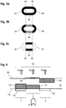
- FIG. 1 shows a schematic plan view of a bank note 10 with a luminescent see-through register 20 according to an embodiment of the invention.
- FIG. 11 shows a cross section through the bank note 10 along the line SS of FIG Fig. 1 .
- the bank note 10 contains a translucent substrate in the form of a bank note paper 12, which has a front side 14 and a rear side 16.
- the banknote paper 12 is translucent both in the visible spectral range and in the UV range, that is to say leads to a certain attenuation of the radiation passing through in both spectral ranges.
- the substrate thickness of the bank note paper 12 is reduced.
- the substrate 12 has a thickness d1 in the basic state (in particular outside the areas 1 and 2 or here also in the first area 1).
- the thickness d2 is smaller than the thickness d1.
- the opacity of the substrate in sub-area 19 is also reduced.
- the banknote paper can alternatively be given a higher light permeability locally by means of transparency, for example by applying a transparent varnish.
- luminescent imprints 22, 24, 26 are arranged both on the front side 14 and on the rear side 16 of the banknote paper 12.
- the imprint 22, 24 is applied in a first area 1 on the front side 14.
- the luminescent print 26 is applied in a second area 2 on the back of the substrate.
- the luminescent prints 22, 24, 26 have the same luminescent color. The prints could also have the same luminescence strength. In the Figure 2 shown is, however, that the luminescent print 26 is present with a greater layer thickness and thus luminescence strength.
- the imprints 22, 24, 26 and thus the first area 1 and the second area 2 are arranged in register with one another. In particular, the areas do not overlap, but rather adjoin one another.
- the imprint 26 on the rear side is congruent with the sub-area of reduced substrate thickness 19.
- the sub-area 19 can - notwithstanding the illustration in FIG Fig. 2 - Be formed on the front side 14 of the substrate.
- the luminescent imprints 22, 24, 26 cannot be recognizable in particular when viewed in visible light, so that the luminescent see-through register 20 represents a hidden security feature that only appears when exposed to UV radiation.
- Fig. 1 the luminescent imprints are shown only schematically, the imprints arranged on the front being shown in a filled representation, the imprints arranged on the back being shown unfilled with a dashed border. With normal daylight or artificial light lighting, the luminescent see-through register 20 is the Fig. 1 not visible.
- the luminescent register image 30 contains an image portion 32 of the luminescent imprint 22 and an image portion 36 of the luminescent imprint 26 adjoining it laterally.
- the imprints 22, 26 form a luminescent see-through register.
- the luminescence register image 30 also contains the image portion 34 of the luminescent print 24, which laterally adjoins the other side of the image portion 36.
- the arrows of the same length for the image components 32, 36, and 34 in Figure 2 indicate the same brightness values for the image components.
- the excitation radiation 8 is weakened by the substrate with a reduced thickness d2.
- the overall image portion 36 is created with a medium luminescence intensity (brightness).
- a higher concentration of the fluorescent substance in the paint can also be used here and below to increase the luminescence strength.
- the excitation radiation 8 excites the luminescence unaffected by the prints 22, 24.
- the luminescence radiation is weakened by the substrate 12 with the thickness d1, so that the image portions 32, 34 likewise arise with a medium luminescence intensity for the viewer of the rear side 16.
- the two parameters substrate thickness reduction (by the value d1-d2) and increased layer thickness of the imprint 26 (and / or fluorescent substance concentration in the imprint) are chosen together so that the same brightness value is achieved for the image portions 32, 36 and 36, 34.
- the parameters must be selected specifically for the excitation opacity and the luminescence opacity of the substrate 12.
- a substrate thickness reduction or an increased luminescence strength alone is sufficient.
- the combination of both parameters avoids layer thicknesses that are too thick (drying problem, special printing technology required ...) or excessive substrate reduction (instability, cracking ...), respectively.
- the image portions 32,36,34 of the luminescence register image 30 are indistinguishable for the viewer in this variant or at least the boundary (s) 33 (35) between the image portions 32,36 (and 36,34 ) not visible.
- the image components 32, 36 and 34 in particular have the same brightness value and the same hue.
- Figure 3b shows the front-side luminescence image produced for the observer of the front side 14 when excited from the front side 14, that is to say in plan view.
- the imprints 22, 24 of the first area 1 on the front side 14 are excited independently of the substrate and luminesce for the observer on the front side, regardless of the substrate.
- the image components 32, 34 are very clearly visible to the viewer (high brightness value).
- the substrate of reduced thickness first acts on the excitation radiation 8 and then on the luminescence radiation of the imprint 26.
- the central image portion 36 which is twice weakened in this respect, is only visible to the viewer with low brightness (or not visible).
- Figure 3c shows the rear side luminescence image that is produced for the viewer of the rear side 16 when excited from the rear side 16, that is to say in plan view.
- the imprint 26 is excited independently of the substrate and its luminescence as an image portion 36 is likewise independent of the substrate, that is to say at a maximum.
- the excitation radiation is weakened with the substrate thickness d1.
- the luminescence radiation is weakened again by the substrate 12 which is not reduced in thickness. As a result, the image portion 32, 24 is no longer recognizable to the viewer of the rear side in plan view in the first area (too low brightness).
- luminescence comparison image For the observer of the front When viewed through transparency (excitation from the rear), a luminescence comparison image is created which is a different image than the luminescence register image which the viewer can recognize. By comparing the two luminescence images, the viewer can check whether there is a difference and thus verify that the luminescence register image actually contains image components from both sides of the substrate.
- the print 26 on the back is excited directly, luminescent due to the increased layer thickness with high intensity.
- the luminescence is only weakened by the substrate of reduced thickness, so it appears to the observer on the front side as an image portion 36 with high brightness.
- the rear-side excitation radiation is greatly weakened by the substrate, unchanged in thickness, and can essentially not generate any luminescence radiation as image components 32, 24 that can be seen by the viewer.
- the parameters are not only selected in such a way that a luminescence register image is created for the substrate 12 with a given opacity.
- the parameters should be selected in such a way that the luminescence comparison image can be sufficiently distinguished from the luminescence register image for the viewer. Whether the luminescence register image is more like the representation in Figure 3a or that of the representation in Figure 3b is subordinate.
- the parameters can, for example, be selected accordingly so that the luminescence comparison image or the representation in FIG Figure 3b (as a contrast to Figure 3a) or Figure 3c (as a contrast to Figure 3b ) corresponds.
- the opacity in the substrate is independent of location.
- a discrepancy was recognized for paper substrates made on a paper screen.
- the UV excitation opacity in the paper substrate is greatly increased on the sieve side. So it decreases significantly towards the opposite side. Therefore, the thickness of the substrate 12 is preferred reduced by removing substrate material from the substrate side. Even a slight reduction in the thickness of the screen side leads to a significant reduction in the UV excitation opacity.
- the substrate side can be used as a front or back.
- excitation in the near UV range that is between 365 and 395 nm, preferably between 376 and 389 nm, can be advantageous, since the opacity of the paper substrates is lower in this range.
- a paper substrate can in particular also contain titanium dioxide, preferably with a concentration of less than 5% or less than 3%, in particular with a concentration between 1% and 2.5%. It is particularly advantageous to use the anatase modification of titanium dioxide, since it does not absorb long-wave UV light as strongly as the rutile modification of titanium dioxide.
- Figure 4 shows an embodiment in which the opacity of the substrate 12 is reduced in areas by transparency.
- the substrate 12 has luminescent imprints 42,46,44 on the front and back, which are applied in register with one another.
- the substrate 12 is provided with a transparency 18 for luminescence radiation under the imprint 42.
- the transparency 18 for luminescence radiation is applied from the rear side 16 in the area of the imprint 44.
- each of the transparencies can be present in a certain partial thickness of the substrate or over the entire thickness of the substrate.
- the excitation transparency 17 of the substrate 12 reduces the opacity of the substrate 12 in this area.
- Figure 4 again shows the resulting luminescence register image 50 for viewing in transparency from the rear.
- the excitation radiation 8 is less attenuated on the way through the substrate 12 in the area of the transparency 17.
- the luminescent material 46 is excited and luminesced with a correspondingly still high excitation intensity.
- the luminescence can be recognized by the viewer as an image portion 56 with medium brightness.
- the prints 42, 44 applied with an increased layer thickness are stimulated immediately and luminesce accordingly intensively.
- the luminescence is attenuated in the substrate 12 - including the transparent subareas 18 -. To the viewer, the image portions 52, 54 appear with the same brightness as the image portion 56.
- the parameters transparency 17, transparency 18 and luminescence strength of the imprints 42, 44 (in the first area) and 46 (in the second area) are adapted to the opacity of the substrate in such a way that the luminescence register image 50 is created.
- the luminescence register image 50 can in particular be generated with different color tones of the image components 52, 54, 56 and the same brightness.
- the imprint 46 with the opposed transparency 17 and the imprint 44 and the opposed transparency 18 can be seen, it can be advantageous to provide the printing and the transparency in each of the areas on opposite sides. On the other hand, it will rarely be helpful to provide the transparency as a background for the print.
- the transparency can also be applied in register or non-register to one another on both sides.
- the luminescent prints 22, 24, 26 have partially different luminescence strengths, that is to say different values for the conversion factor K.
- the relative proportion of light passing through the substrate 12, radiation may be indicated by transmittance Tuv or T vis.
- a substrate with high excitation opacity small Tuv, eg: 0.15) and lower luminescence opacity (greater T vis , eg: 0.4) is assumed.
- Fig. 4 shows, however, an example with low excitation opacity and high luminescence opacity.
- the parameters are to be selected in areas such that the luminescence register image differs from the luminescence comparison image in a recognizable manner for the viewer.
- the intensities in the two areas 1, 2 are considered under the simplified assumption of the same luminescence strength.
- I UV in let the intensity of the UV excitation radiation 8 from that of the front side.
- the front-side imprints 22, 24 are excited with the non-weakened UV radiation 8, the visible luminescence radiation generated but is weakened by the substrate material 12.
- the luminescent imprints 22, 24, 26 thus form a luminescent see-through register. It is possible that the complete image information is only visible when the bank note 10 is from one side of the substrate 12 (front side 14 in Fig. 2 ) is exposed to UV radiation 8, and the luminescent image 30 on the opposite side of the substrate (rear side 16 in Fig. 2 ) is looked at.
- the see-through register 20 Another special feature of the see-through register 20 is the side-dependency of the brightness distribution of the displayed luminescence image.
- the luminescence comparison image is produced when the bank note 10 is turned over and viewed again in transparency.
- T UV, 1 is significantly greater than T vis, 2
- I vis, R, 1 is also significantly greater than I vis, R, 2 and the brightness values of the image components are therefore clearly different.
- This side dependency of the appearance of the generated luminescence images can be used as a further authenticity feature or for verification of the security feature 20.
- the conversion factor K of the luminescent imprints on the front and back is the same, the conversion factor can of course also be selected to be of different sizes, so that additional possibilities for variation arise.
- K denotes the conversion factor of the luminescent imprints 22, 26 arranged on the front side
- K R denotes the conversion factor of the luminescent imprints 24 arranged on the rear side
- the appearance of the generated luminescence images when viewed through is preferably side-dependent. By coordinating the conversion factors and the reduced opacities, however, a page-independent appearance could also be created.
- Figure 5 shows as a further embodiment of the invention a data carrier 20 with a translucent substrate 12, in which luminescent imprints 62, 64 are applied in a first area on the front side 14 of the substrate and in a second area on the back 16 of the substrate a luminescent imprint 66 in a partial area 19 of reduced substrate thickness lies.
- a substrate 12 with high excitation opacity is assumed, so that the three available parameters are used for adaptation in the second area.
- an excitation transparency 17 and an increased luminescence strength of the imprint 66 for example through an increased luminescence substance concentration, are provided.
- the luminescence register image 70 comprises image portions 71, 72, 74, 75 of the front-side imprint 62, 64 in the first area 1 and the image portion 76 of the rear-side imprint 66 in the second area. Since the imprint 62, 64 of the first area 1 extends beyond the partial area 19 of the substrate thickness reduction, the image portions 71, 75 have a lower brightness for the viewer than the image portions 72, 74. Because of the excitation opacity, the luminescent imprints 67, 68 applied in a third area on the rear side of the substrate do not contribute to the luminescence register image 70 or do not luminesce when excited from the front.
- the difference in the brightness of the laterally adjoining image components 72, 76 and 76, 74 can be selected in the luminescence register image 70 such that it cannot be seen by the viewer.
- the image portions 72, 76 and 76, 74 have the same color tone, the boundary cannot be seen by the viewer.
- the image components 72, 76 or 76, 74 differ in color and / or if the brightness value (possibly the same color shade) is different, the boundary is recognizable to the viewer.
- the see-through register 20 - already without the further imprints 67, 68 - is designed in such a way that the luminescence register image 70 when stimulated on the front side produces a luminescence comparison image that is distinguishable for the viewer when stimulated on the back side.
- the excitation on the back excites the imprint 66 directly to luminescence, which is only slightly weakened by the substrate of reduced thickness.
- the front-side imprints 62, 64 are only slightly excited in the area of the substrate reduction and not at all outside.
- the imprints 62, 64 contain luminescent substances of a first color, here red, and the imprint 66 luminescent substances of a second color, here green, a luminescence register image with differently colored image components (red and green) is created when the front side is excited.
- the uniformly colored (green) luminescence comparison image generated upon excitation from the rear is particularly easy to recognize as different for the viewer.
- the optional further imprints 67, 68 can further intensify the difference between the luminescence register image and the luminescence comparison image, since, for example, they are only (or primarily) visible to the viewer in transparency in the luminescence comparison image.
- the further imprints can have an independent motif in particular have independently (of the second area) selectable outer contour.
- the luminescent see-through register 20 can, as just exemplified Figure 5 described but generally applicable, be incorporated into a luminescent overall design on the front and / or a luminescent overall design on the back.
- the luminescence register image can be adapted to the visual design of the front and / or the back or integrated into the visual design, which is formed by non-luminescent, in particular multicolored, imprints and / or other optical security features (not shown). If one of the luminescent imprints were to be replaced by a colored imprint in one of the two areas, one arrives at a simple luminescent image which is in register with a colored imprint.
- Luminescence images can also represent true color images by additive color mixing, which are generated, for example, by the luminescence basic dyes luminescence green, luminescence red and luminescence blue.
- Figure 6 shows an embodiment with a luminescent luminescent register image 90 that is luminescent in true colors.
- Luminescent green, luminescent red and luminescent blue which are printed in corresponding color layers 87, 88, 89, are used as the basic colors.
- a luminescent imprint 82, 84 each with three layers of color (or color components), is applied to the front.
- the second area 2 only the two colored layers 88, 89, for example luminescent red and luminescent blue, are applied on the front side.
- the color layer missing on the front side is applied as an imprint 86 on the rear side in register.
- a true color image portion is located within each of the two areas of the luminescent register image 90. The intensity of the colors thus varies locally, for example according to the resolution available for printing from pixel to pixel.
- the luminescence register image 90 is formed in the first area 1 by an image component which arises from the true-color (RGB) luminescence of the imprints 82, 84, which is weakened by the substrate 12 with its luminescence opacity.
- the substrate here reduced in thickness, reduces the intensity of the red and blue luminescence radiation of the imprint 83 in accordance with its visual opacity, and the intensity of the excitation radiation is reduced in accordance with the UV opacity.
- the green luminescence of the print 86 on the back complements the red-blue luminescence of the front to form a true color image.
- the reduction in thickness of the substrate in the sub-area 19 and / or the basic luminescence strength of the imprint 86 are selected such that a uniform, true-color luminescence register image 90 results for the viewer.
- the base luminescence intensity is seen as a luminescence intensity from which the local variation occurs within the area 2.
- the basic luminescence intensity is the mean value of the luminescence intensity in the imprint 86.
- a luminescence register image 90 in real colors is created for the viewer.
- the viewer does not recognize the boundary between the areas (seamless luminescence register image 90).
- the boundary between the first and the second area is emphasized for the viewer.
- the basic colors can also be arranged next to one another in the grid or only partially one above the other.
- the luminescence comparison image 91 is created for the observer on the front side.
- the luminescence comparison image 91 contains an image portion in the second area 2 that is generated by the (green) print 86 on the back side.
- the rear imprint 85 is not excited from the front. It can, for example, contain luminescent white as a luminescent dye and / or comprise a partial image held in gray levels.
- the back imprint 85 generates an image portion of the luminescence comparison image 91 when the back is excited in the third area 3.
- the luminescence comparison image 91 thus comprises a colored (green) and a non-colored (white) partial image.
- the partial image of the second area is thus contained both in the luminescence comparison image 91 (monochrome) and in the luminescence register image 90 (colored). The side dependency can thus be verified particularly easily for the viewer.
Landscapes
- Engineering & Computer Science (AREA)
- Manufacturing & Machinery (AREA)
- Mechanical Engineering (AREA)
- Business, Economics & Management (AREA)
- Optics & Photonics (AREA)
- Toxicology (AREA)
- Electromagnetism (AREA)
- Health & Medical Sciences (AREA)
- Physics & Mathematics (AREA)
- General Health & Medical Sciences (AREA)
- Accounting & Taxation (AREA)
- Finance (AREA)
- Chemical & Material Sciences (AREA)
- Chemical Kinetics & Catalysis (AREA)
- General Chemical & Material Sciences (AREA)
- Printing Methods (AREA)
- Inspection Of Paper Currency And Valuable Securities (AREA)
- Credit Cards Or The Like (AREA)
Claims (15)
- Support de données, en particulier document de valeur ou de sécurité, comprenant un substrat translucide (12) ayant une face avant et une face arrière ;
cependant que, dans une première zone (1), du matériau luminescent (22) est appliqué sur la face avant du substrat (12) ;
cependant que, dans une deuxième zone (2), du matériau luminescent (26) est appliqué sur la face arrière du substrat (12) ;
cependant que la première zone (1) et la deuxième zone (2) sont agencées en registre l'une par rapport à l'autre ; et
cependant que, pour l'observateur, lors d'une excitation (8) depuis la face avant, une image luminescente (30) est générée en transmission, laquelle comprend une part d'image (32) de la première zone (1) et comprend une part d'image (36) de la deuxième zone (2) luminescente, latéralement adjacente à la part d'image (32) de la première zone (1) ; caractérisé en ce que
dans la première zone (1) et dans la deuxième zone (2), au moins un paramètre, une opacité du substrat translucide (12) et/ou une intensité de luminescence du matériau luminescent est choisie différemment en fonction de la zone, et
les parts d'image (32, 36) adjacentes entre elles de l'image luminescente (30) présentent la même valeur de luminosité. - Support de données selon la revendication 1, caractérisé en ce que, pour l'observateur, lors d'une excitation (8) côté avant, une image luminescente (30) est générée en transmission, et
lors d'une excitation côté arrière, une image luminescente de côté arrière perceptiblement autre est générée en transmission. - Support de données selon la revendication 2, caractérisé en ce que, dans l'image luminescente de côté arrière, soit seulement seulement une part d'image d'une des deux zones luminescentes (1, 2) est contenue, soit une différence des valeurs de luminosité des parts d'image des deux zones luminescentes (1, 2) est perceptiblement élevée.
- Support de données selon une des revendications précédentes, caractérisé en ce que le substrat translucide (12) comprend une zone partielle (19) d'épaisseur réduite de substrat et/ou au moins une zone partielle (17, 18) rendue transparente.
- Support de données selon la revendication 4, caractérisé en ce que la zone partielle (19) d'épaisseur réduite de substrat est constituée par un enlèvement physique de matériau de substrat après la fabrication du substrat.
- Support de données selon la revendication 5, caractérisé en ce que le substrat translucide est un substrat basé sur des fibres qui est fabriqué au moyen d'un tamis, cependant que le matériau du substrat est enlevé physiquement du côté tamis du substrat.
- Support de données selon la revendication 4, caractérisé en ce que le substrat translucide est un substrat basé sur des fibres et que la zone partielle d'épaisseur réduite de substrat est constituée par un filigrane généré lors de la fabrication, à base de fibres, du substrat, cependant que la zone partielle d'épaisseur réduite de substrat est de préférence en plus rendue transparente.
- Support de données selon une des revendications de 4 à 7, caractérisé en ce que la zone partielle (18) rendue transparente est rendue transparente de manière luminescente et/ou que la zone partielle (17) rendue transparente est rendue transparente en excitation.
- Support de données selon une des revendications précédentes, caractérisé en ce que la zone luminescente (1) de la face avant et/ou la zone luminescente (2) de la face arrière s'étendent au-delà de la zone partielle d'opacité réduite.
- Support de données selon une des revendications précédentes, caractérisé en ce que le matériau luminescent (22, 24) est appliqué en différente épaisseur de couche et/ou concentration de substance luminescente.
- Support de données selon au moins une des revendications de 1 à 10, caractérisé en ce que, pour l'observateur, la transition entre les deux parts d'image (22, 26) dans l'image luminescente (30) n'est pas reconnaissable et/ou que le motif composé de l'image luminescente en registre (30) n'est générée pour l'observateur que dans le cas d'une excitation côté avant en transmission.
- Support de données selon au moins une des revendications de 1 à 11, caractérisé en ce que le substrat translucide est un substrat basé sur des fibres, en particulier un substrat en papier ou la strate en papier d'un substrat composite.
- Procédé de fabrication d'un support de données, dans lequel- un substrat translucide est mis à disposition ;- sur la face avant du substrat dans une première zone, et sur la face arrière du substrat dans une deuxième zone agencée en registre par rapport à la première zone, du matériau luminescent est appliqué ;
cependant que, dans la première zone (1) et/ou dans la deuxième zone (2), une zone partielle d'opacité réduite du substrat translucide (12) est générée et/ou que, dans les deux zones, une intensité de luminescence du matériau luminescent est choisie différemment en fonction de la zone, cependant que les deux zones constituent un registre en transmission luminescent, lequel, pour l'observateur, génère en transmission lors d'une excitation (8) depuis la face avant une image luminescente (30), laquelle comprend une part d'image (32) de la première zone (1) et une part d'image (36), de la deuxième zone (2) luminescente, latéralement adjacente à la part d'image (32) de la première zone (1), et
cependant que les deux parts d'image (32, 36) adjacentes entre elles de l'image luminescente (30) présentent la même valeur de luminosité. - Procédé selon la revendication 13, caractérisé en ce que, en tant que substrat translucide, un substrat en papier ou un substrat composite ayant une strate en papier est mis à disposition, et que, lors de la fabrication du papier du ou de la strate en papier, un filigrane qui constitue une zone partielle d'épaisseur réduite est généré.
- Procédé selon la revendication 13, caractérisé en ce qu'une zone partielle d'épaisseur réduite est générée par un enlèvement physique de matériau de substrat après la fabrication du substrat, en particulier par ablation au laser ou à l'aide d'une fraiseuse mécanique, ou qu'une zone partielle d'épaisseur réduite est générée par mise en place d'un agent rendant transparent.
Applications Claiming Priority (1)
| Application Number | Priority Date | Filing Date | Title |
|---|---|---|---|
| DE102016015500.0A DE102016015500A1 (de) | 2016-12-23 | 2016-12-23 | Datenträger mit Lumineszenzbereichen |
Publications (2)
| Publication Number | Publication Date |
|---|---|
| EP3339049A1 EP3339049A1 (fr) | 2018-06-27 |
| EP3339049B1 true EP3339049B1 (fr) | 2021-03-24 |
Family
ID=60888074
Family Applications (1)
| Application Number | Title | Priority Date | Filing Date |
|---|---|---|---|
| EP17002061.4A Active EP3339049B1 (fr) | 2016-12-23 | 2017-12-22 | Support de données avec des zones luminescentes |
Country Status (2)
| Country | Link |
|---|---|
| EP (1) | EP3339049B1 (fr) |
| DE (1) | DE102016015500A1 (fr) |
Families Citing this family (2)
| Publication number | Priority date | Publication date | Assignee | Title |
|---|---|---|---|---|
| DE102020108081A1 (de) | 2020-03-24 | 2021-09-30 | Koenig & Bauer Ag | Verfahren zur Herstellung eines als Durchsichtsregister auf einem Sicherheitsdokument wirksamen Sicherheitsmerkmals sowie Sicherheitsdokument mit einem als Durchsichtsregister auf einem Sicherheitsdokument wirksamen Sicherheitsmerkmal |
| DE102020108080A1 (de) | 2020-03-24 | 2021-09-30 | Koenig & Bauer Ag | Verfahren zur Herstellung eines als Durchsichtsregister auf einem Sicherheitsdokument wirksamen Sicherheitsmerkmals, Verfahren zum Herstellen von Sicherheitsdokumenten sowie Sicherheitsdokument |
Family Cites Families (9)
| Publication number | Priority date | Publication date | Assignee | Title |
|---|---|---|---|---|
| CA2313162A1 (fr) * | 1998-10-07 | 2000-04-13 | Hideo Kurihara | Feuille empechant la falsification |
| GB0228303D0 (en) * | 2002-12-04 | 2003-01-08 | Rue De Int Ltd | Security device and method |
| DE102005022518A1 (de) * | 2005-05-11 | 2006-11-16 | Giesecke & Devrient Gmbh | Sicherheitspapier und Verfahren zu seiner Herstellung |
| GB0601635D0 (en) * | 2006-01-26 | 2006-03-08 | Rue De Int Ltd | Security document |
| FR2945551B1 (fr) * | 2009-05-13 | 2011-08-26 | Oberthur Technologies | Procede de fabrication d'un element de securite pour document de securite. |
| DE102011012225A1 (de) | 2011-02-24 | 2012-08-30 | Giesecke & Devrient Gmbh | Individualisiertes Durchsichtregister |
| DE102011122246A1 (de) | 2011-12-23 | 2013-06-27 | Giesecke & Devrient Gmbh | Sicherheitsmerkmal mit mehreren Komponenten |
| DE102012111054B4 (de) * | 2012-11-16 | 2023-10-19 | Bundesdruckerei Gmbh | Sicherheitselement für ein Wert- und/oder Sicherheitsdokument |
| DE102013008505A1 (de) | 2012-11-30 | 2014-06-05 | Giesecke & Devrient Gmbh | Sicherheitselement, Herstellungsverfahren, mit dem Sicherheitselement ausgestatteter Datenträger und Verfahren zum Überprüfen der Echtheit |
-
2016
- 2016-12-23 DE DE102016015500.0A patent/DE102016015500A1/de not_active Withdrawn
-
2017
- 2017-12-22 EP EP17002061.4A patent/EP3339049B1/fr active Active
Non-Patent Citations (1)
| Title |
|---|
| None * |
Also Published As
| Publication number | Publication date |
|---|---|
| EP3339049A1 (fr) | 2018-06-27 |
| DE102016015500A1 (de) | 2018-06-28 |
Similar Documents
| Publication | Publication Date | Title |
|---|---|---|
| DE2901150C2 (de) | Ausweiskarte mit im Auf- und Durchlicht prüf baren Echtheitsmerkmalen und Verfahren zu ihrer Herstellung | |
| EP2323852B1 (fr) | Élément de sécurité comportant des informations en lumière réfléchie et en lumière transmise | |
| EP0659587B1 (fr) | Papier de sécurité avec élément de sécurité en forme de fil ou de bande | |
| EP2448767B1 (fr) | Élément de sécurité et procédé de production correspondant | |
| DE4344298A1 (de) | Sicherheitspapier mit einem faden- oder bandförmigen Sicherheitselement | |
| EP2817155B1 (fr) | Procede avec alignement entre un element d'impression et un filigrane | |
| EP2318884B1 (fr) | Kinégramme binaire | |
| EP3513984B1 (fr) | Élément de sécurité pourvu de zone luminescente à motif | |
| EP3825141B1 (fr) | Element luminescent avec zone de motif luminescente | |
| EP3470236B1 (fr) | Support de données pourvu de zones à motif luminescentes | |
| EP3339049B1 (fr) | Support de données avec des zones luminescentes | |
| EP3452299B1 (fr) | Élément de sécurité doté d'une impression luminescente | |
| EP3225417B1 (fr) | Support de données doté d'une impression | |
| EP1744901A1 (fr) | Element de securite et son procede de production | |
| EP2448766B1 (fr) | Élément de sécurité et procédé de production correspondant | |
| DE102019006315A1 (de) | Optisch variables Sicherheitselement | |
| EP2678170A2 (fr) | Impression simultanée individualisée | |
| DE102020002429A1 (de) | Datenträger, insbesondere ein Wert- oder Sicherheitsdokument | |
| EP3286010B1 (fr) | Procédé servant à fabriquer un élément de sécurité avec un alignement entre un élément d'impression et un filigrane | |
| EP3279004A1 (fr) | Élément de sécurité, procédé de fabrication d'un élément de sécurité ainsi que document de valeur pourvu d'un tel élément de sécurité | |
| EP4183592A1 (fr) | Élément de sécurité transparent, support de données et procédé de fabrication | |
| DE102016004513A1 (de) | Wert- und Sicherheitspapier mit Rückseiteninformation |
Legal Events
| Date | Code | Title | Description |
|---|---|---|---|
| PUAI | Public reference made under article 153(3) epc to a published international application that has entered the european phase |
Free format text: ORIGINAL CODE: 0009012 |
|
| STAA | Information on the status of an ep patent application or granted ep patent |
Free format text: STATUS: THE APPLICATION HAS BEEN PUBLISHED |
|
| AK | Designated contracting states |
Kind code of ref document: A1 Designated state(s): AL AT BE BG CH CY CZ DE DK EE ES FI FR GB GR HR HU IE IS IT LI LT LU LV MC MK MT NL NO PL PT RO RS SE SI SK SM TR |
|
| AX | Request for extension of the european patent |
Extension state: BA ME |
|
| STAA | Information on the status of an ep patent application or granted ep patent |
Free format text: STATUS: REQUEST FOR EXAMINATION WAS MADE |
|
| 17P | Request for examination filed |
Effective date: 20190102 |
|
| RBV | Designated contracting states (corrected) |
Designated state(s): AL AT BE BG CH CY CZ DE DK EE ES FI FR GB GR HR HU IE IS IT LI LT LU LV MC MK MT NL NO PL PT RO RS SE SI SK SM TR |
|
| GRAP | Despatch of communication of intention to grant a patent |
Free format text: ORIGINAL CODE: EPIDOSNIGR1 |
|
| STAA | Information on the status of an ep patent application or granted ep patent |
Free format text: STATUS: GRANT OF PATENT IS INTENDED |
|
| INTG | Intention to grant announced |
Effective date: 20200825 |
|
| GRAJ | Information related to disapproval of communication of intention to grant by the applicant or resumption of examination proceedings by the epo deleted |
Free format text: ORIGINAL CODE: EPIDOSDIGR1 |
|
| STAA | Information on the status of an ep patent application or granted ep patent |
Free format text: STATUS: REQUEST FOR EXAMINATION WAS MADE |
|
| GRAP | Despatch of communication of intention to grant a patent |
Free format text: ORIGINAL CODE: EPIDOSNIGR1 |
|
| STAA | Information on the status of an ep patent application or granted ep patent |
Free format text: STATUS: GRANT OF PATENT IS INTENDED |
|
| INTC | Intention to grant announced (deleted) | ||
| INTG | Intention to grant announced |
Effective date: 20201030 |
|
| GRAS | Grant fee paid |
Free format text: ORIGINAL CODE: EPIDOSNIGR3 |
|
| GRAA | (expected) grant |
Free format text: ORIGINAL CODE: 0009210 |
|
| STAA | Information on the status of an ep patent application or granted ep patent |
Free format text: STATUS: THE PATENT HAS BEEN GRANTED |
|
| AK | Designated contracting states |
Kind code of ref document: B1 Designated state(s): AL AT BE BG CH CY CZ DE DK EE ES FI FR GB GR HR HU IE IS IT LI LT LU LV MC MK MT NL NO PL PT RO RS SE SI SK SM TR |
|
| REG | Reference to a national code |
Ref country code: GB Ref legal event code: FG4D Free format text: NOT ENGLISH |
|
| REG | Reference to a national code |
Ref country code: CH Ref legal event code: EP |
|
| REG | Reference to a national code |
Ref country code: DE Ref legal event code: R096 Ref document number: 502017009771 Country of ref document: DE |
|
| REG | Reference to a national code |
Ref country code: IE Ref legal event code: FG4D Free format text: LANGUAGE OF EP DOCUMENT: GERMAN |
|
| REG | Reference to a national code |
Ref country code: AT Ref legal event code: REF Ref document number: 1374107 Country of ref document: AT Kind code of ref document: T Effective date: 20210415 |
|
| REG | Reference to a national code |
Ref country code: LT Ref legal event code: MG9D |
|
| PG25 | Lapsed in a contracting state [announced via postgrant information from national office to epo] |
Ref country code: HR Free format text: LAPSE BECAUSE OF FAILURE TO SUBMIT A TRANSLATION OF THE DESCRIPTION OR TO PAY THE FEE WITHIN THE PRESCRIBED TIME-LIMIT Effective date: 20210324 Ref country code: FI Free format text: LAPSE BECAUSE OF FAILURE TO SUBMIT A TRANSLATION OF THE DESCRIPTION OR TO PAY THE FEE WITHIN THE PRESCRIBED TIME-LIMIT Effective date: 20210324 Ref country code: GR Free format text: LAPSE BECAUSE OF FAILURE TO SUBMIT A TRANSLATION OF THE DESCRIPTION OR TO PAY THE FEE WITHIN THE PRESCRIBED TIME-LIMIT Effective date: 20210625 Ref country code: NO Free format text: LAPSE BECAUSE OF FAILURE TO SUBMIT A TRANSLATION OF THE DESCRIPTION OR TO PAY THE FEE WITHIN THE PRESCRIBED TIME-LIMIT Effective date: 20210624 Ref country code: BG Free format text: LAPSE BECAUSE OF FAILURE TO SUBMIT A TRANSLATION OF THE DESCRIPTION OR TO PAY THE FEE WITHIN THE PRESCRIBED TIME-LIMIT Effective date: 20210624 |
|
| PG25 | Lapsed in a contracting state [announced via postgrant information from national office to epo] |
Ref country code: SE Free format text: LAPSE BECAUSE OF FAILURE TO SUBMIT A TRANSLATION OF THE DESCRIPTION OR TO PAY THE FEE WITHIN THE PRESCRIBED TIME-LIMIT Effective date: 20210324 Ref country code: LV Free format text: LAPSE BECAUSE OF FAILURE TO SUBMIT A TRANSLATION OF THE DESCRIPTION OR TO PAY THE FEE WITHIN THE PRESCRIBED TIME-LIMIT Effective date: 20210324 Ref country code: RS Free format text: LAPSE BECAUSE OF FAILURE TO SUBMIT A TRANSLATION OF THE DESCRIPTION OR TO PAY THE FEE WITHIN THE PRESCRIBED TIME-LIMIT Effective date: 20210324 |
|
| REG | Reference to a national code |
Ref country code: NL Ref legal event code: MP Effective date: 20210324 |
|
| PG25 | Lapsed in a contracting state [announced via postgrant information from national office to epo] |
Ref country code: NL Free format text: LAPSE BECAUSE OF FAILURE TO SUBMIT A TRANSLATION OF THE DESCRIPTION OR TO PAY THE FEE WITHIN THE PRESCRIBED TIME-LIMIT Effective date: 20210324 |
|
| PG25 | Lapsed in a contracting state [announced via postgrant information from national office to epo] |
Ref country code: CZ Free format text: LAPSE BECAUSE OF FAILURE TO SUBMIT A TRANSLATION OF THE DESCRIPTION OR TO PAY THE FEE WITHIN THE PRESCRIBED TIME-LIMIT Effective date: 20210324 Ref country code: EE Free format text: LAPSE BECAUSE OF FAILURE TO SUBMIT A TRANSLATION OF THE DESCRIPTION OR TO PAY THE FEE WITHIN THE PRESCRIBED TIME-LIMIT Effective date: 20210324 Ref country code: LT Free format text: LAPSE BECAUSE OF FAILURE TO SUBMIT A TRANSLATION OF THE DESCRIPTION OR TO PAY THE FEE WITHIN THE PRESCRIBED TIME-LIMIT Effective date: 20210324 Ref country code: SM Free format text: LAPSE BECAUSE OF FAILURE TO SUBMIT A TRANSLATION OF THE DESCRIPTION OR TO PAY THE FEE WITHIN THE PRESCRIBED TIME-LIMIT Effective date: 20210324 |
|
| PG25 | Lapsed in a contracting state [announced via postgrant information from national office to epo] |
Ref country code: RO Free format text: LAPSE BECAUSE OF FAILURE TO SUBMIT A TRANSLATION OF THE DESCRIPTION OR TO PAY THE FEE WITHIN THE PRESCRIBED TIME-LIMIT Effective date: 20210324 Ref country code: SK Free format text: LAPSE BECAUSE OF FAILURE TO SUBMIT A TRANSLATION OF THE DESCRIPTION OR TO PAY THE FEE WITHIN THE PRESCRIBED TIME-LIMIT Effective date: 20210324 Ref country code: PT Free format text: LAPSE BECAUSE OF FAILURE TO SUBMIT A TRANSLATION OF THE DESCRIPTION OR TO PAY THE FEE WITHIN THE PRESCRIBED TIME-LIMIT Effective date: 20210726 Ref country code: PL Free format text: LAPSE BECAUSE OF FAILURE TO SUBMIT A TRANSLATION OF THE DESCRIPTION OR TO PAY THE FEE WITHIN THE PRESCRIBED TIME-LIMIT Effective date: 20210324 Ref country code: IS Free format text: LAPSE BECAUSE OF FAILURE TO SUBMIT A TRANSLATION OF THE DESCRIPTION OR TO PAY THE FEE WITHIN THE PRESCRIBED TIME-LIMIT Effective date: 20210724 |
|
| REG | Reference to a national code |
Ref country code: DE Ref legal event code: R097 Ref document number: 502017009771 Country of ref document: DE |
|
| PG25 | Lapsed in a contracting state [announced via postgrant information from national office to epo] |
Ref country code: DK Free format text: LAPSE BECAUSE OF FAILURE TO SUBMIT A TRANSLATION OF THE DESCRIPTION OR TO PAY THE FEE WITHIN THE PRESCRIBED TIME-LIMIT Effective date: 20210324 Ref country code: AL Free format text: LAPSE BECAUSE OF FAILURE TO SUBMIT A TRANSLATION OF THE DESCRIPTION OR TO PAY THE FEE WITHIN THE PRESCRIBED TIME-LIMIT Effective date: 20210324 Ref country code: ES Free format text: LAPSE BECAUSE OF FAILURE TO SUBMIT A TRANSLATION OF THE DESCRIPTION OR TO PAY THE FEE WITHIN THE PRESCRIBED TIME-LIMIT Effective date: 20210324 |
|
| PGFP | Annual fee paid to national office [announced via postgrant information from national office to epo] |
Ref country code: GB Payment date: 20211222 Year of fee payment: 5 Ref country code: FR Payment date: 20211220 Year of fee payment: 5 |
|
| PLBE | No opposition filed within time limit |
Free format text: ORIGINAL CODE: 0009261 |
|
| STAA | Information on the status of an ep patent application or granted ep patent |
Free format text: STATUS: NO OPPOSITION FILED WITHIN TIME LIMIT |
|
| PG25 | Lapsed in a contracting state [announced via postgrant information from national office to epo] |
Ref country code: SI Free format text: LAPSE BECAUSE OF FAILURE TO SUBMIT A TRANSLATION OF THE DESCRIPTION OR TO PAY THE FEE WITHIN THE PRESCRIBED TIME-LIMIT Effective date: 20210324 |
|
| 26N | No opposition filed |
Effective date: 20220104 |
|
| PGFP | Annual fee paid to national office [announced via postgrant information from national office to epo] |
Ref country code: MT Payment date: 20211222 Year of fee payment: 5 |
|
| PG25 | Lapsed in a contracting state [announced via postgrant information from national office to epo] |
Ref country code: IS Free format text: LAPSE BECAUSE OF FAILURE TO SUBMIT A TRANSLATION OF THE DESCRIPTION OR TO PAY THE FEE WITHIN THE PRESCRIBED TIME-LIMIT Effective date: 20210724 |
|
| REG | Reference to a national code |
Ref country code: DE Ref legal event code: R119 Ref document number: 502017009771 Country of ref document: DE |
|
| PG25 | Lapsed in a contracting state [announced via postgrant information from national office to epo] |
Ref country code: MC Free format text: LAPSE BECAUSE OF FAILURE TO SUBMIT A TRANSLATION OF THE DESCRIPTION OR TO PAY THE FEE WITHIN THE PRESCRIBED TIME-LIMIT Effective date: 20210324 |
|
| REG | Reference to a national code |
Ref country code: CH Ref legal event code: PL |
|
| REG | Reference to a national code |
Ref country code: BE Ref legal event code: MM Effective date: 20211231 |
|
| PG25 | Lapsed in a contracting state [announced via postgrant information from national office to epo] |
Ref country code: LU Free format text: LAPSE BECAUSE OF NON-PAYMENT OF DUE FEES Effective date: 20211222 Ref country code: IE Free format text: LAPSE BECAUSE OF NON-PAYMENT OF DUE FEES Effective date: 20211222 Ref country code: DE Free format text: LAPSE BECAUSE OF NON-PAYMENT OF DUE FEES Effective date: 20220701 |
|
| PG25 | Lapsed in a contracting state [announced via postgrant information from national office to epo] |
Ref country code: BE Free format text: LAPSE BECAUSE OF NON-PAYMENT OF DUE FEES Effective date: 20211231 |
|
| PG25 | Lapsed in a contracting state [announced via postgrant information from national office to epo] |
Ref country code: LI Free format text: LAPSE BECAUSE OF NON-PAYMENT OF DUE FEES Effective date: 20211231 Ref country code: CH Free format text: LAPSE BECAUSE OF NON-PAYMENT OF DUE FEES Effective date: 20211231 |
|
| PG25 | Lapsed in a contracting state [announced via postgrant information from national office to epo] |
Ref country code: IT Free format text: LAPSE BECAUSE OF FAILURE TO SUBMIT A TRANSLATION OF THE DESCRIPTION OR TO PAY THE FEE WITHIN THE PRESCRIBED TIME-LIMIT Effective date: 20210324 |
|
| PG25 | Lapsed in a contracting state [announced via postgrant information from national office to epo] |
Ref country code: HU Free format text: LAPSE BECAUSE OF FAILURE TO SUBMIT A TRANSLATION OF THE DESCRIPTION OR TO PAY THE FEE WITHIN THE PRESCRIBED TIME-LIMIT; INVALID AB INITIO Effective date: 20171222 |
|
| PG25 | Lapsed in a contracting state [announced via postgrant information from national office to epo] |
Ref country code: CY Free format text: LAPSE BECAUSE OF FAILURE TO SUBMIT A TRANSLATION OF THE DESCRIPTION OR TO PAY THE FEE WITHIN THE PRESCRIBED TIME-LIMIT Effective date: 20210324 |
|
| GBPC | Gb: european patent ceased through non-payment of renewal fee |
Effective date: 20221222 |
|
| PG25 | Lapsed in a contracting state [announced via postgrant information from national office to epo] |
Ref country code: GB Free format text: LAPSE BECAUSE OF NON-PAYMENT OF DUE FEES Effective date: 20221222 |
|
| PG25 | Lapsed in a contracting state [announced via postgrant information from national office to epo] |
Ref country code: FR Free format text: LAPSE BECAUSE OF NON-PAYMENT OF DUE FEES Effective date: 20221231 |
|
| REG | Reference to a national code |
Ref country code: AT Ref legal event code: MM01 Ref document number: 1374107 Country of ref document: AT Kind code of ref document: T Effective date: 20221222 |
|
| PG25 | Lapsed in a contracting state [announced via postgrant information from national office to epo] |
Ref country code: AT Free format text: LAPSE BECAUSE OF NON-PAYMENT OF DUE FEES Effective date: 20221222 |
|
| PG25 | Lapsed in a contracting state [announced via postgrant information from national office to epo] |
Ref country code: MK Free format text: LAPSE BECAUSE OF FAILURE TO SUBMIT A TRANSLATION OF THE DESCRIPTION OR TO PAY THE FEE WITHIN THE PRESCRIBED TIME-LIMIT Effective date: 20210324 Ref country code: AT Free format text: LAPSE BECAUSE OF NON-PAYMENT OF DUE FEES Effective date: 20221222 |