EP3338923A1 - Annular drill bit with a spiral-shaped drill shaft and method for producing a spiral-shaped drill shaft for a drill bit - Google Patents
Annular drill bit with a spiral-shaped drill shaft and method for producing a spiral-shaped drill shaft for a drill bit Download PDFInfo
- Publication number
- EP3338923A1 EP3338923A1 EP16206533.8A EP16206533A EP3338923A1 EP 3338923 A1 EP3338923 A1 EP 3338923A1 EP 16206533 A EP16206533 A EP 16206533A EP 3338923 A1 EP3338923 A1 EP 3338923A1
- Authority
- EP
- European Patent Office
- Prior art keywords
- drill
- drill bit
- spiral
- shank
- suture
- Prior art date
- Legal status (The legal status is an assumption and is not a legal conclusion. Google has not performed a legal analysis and makes no representation as to the accuracy of the status listed.)
- Withdrawn
Links
- 238000004519 manufacturing process Methods 0.000 title claims description 11
- 239000000463 material Substances 0.000 claims description 98
- 238000005553 drilling Methods 0.000 claims description 56
- 238000000034 method Methods 0.000 claims description 10
- 239000003356 suture material Substances 0.000 claims description 7
- 238000005304 joining Methods 0.000 claims description 4
- 230000037431 insertion Effects 0.000 abstract 1
- 238000003780 insertion Methods 0.000 abstract 1
- 238000005520 cutting process Methods 0.000 description 58
- 238000001816 cooling Methods 0.000 description 37
- 239000007788 liquid Substances 0.000 description 35
- 239000012530 fluid Substances 0.000 description 14
- 238000003466 welding Methods 0.000 description 12
- 230000002262 irrigation Effects 0.000 description 6
- 238000003973 irrigation Methods 0.000 description 6
- 102100037010 Fidgetin Human genes 0.000 description 4
- 101000878296 Homo sapiens Fidgetin Proteins 0.000 description 4
- 238000007373 indentation Methods 0.000 description 4
- 239000006228 supernatant Substances 0.000 description 4
- 238000002788 crimping Methods 0.000 description 3
- 238000011161 development Methods 0.000 description 3
- 230000018109 developmental process Effects 0.000 description 3
- 238000011010 flushing procedure Methods 0.000 description 3
- 230000007704 transition Effects 0.000 description 3
- 239000012809 cooling fluid Substances 0.000 description 2
- 230000000593 degrading effect Effects 0.000 description 2
- 238000000465 moulding Methods 0.000 description 2
- 238000004886 process control Methods 0.000 description 2
- 238000012545 processing Methods 0.000 description 2
- 238000005086 pumping Methods 0.000 description 2
- 239000000853 adhesive Substances 0.000 description 1
- 230000001070 adhesive effect Effects 0.000 description 1
- 238000010276 construction Methods 0.000 description 1
- 239000002826 coolant Substances 0.000 description 1
- 239000000110 cooling liquid Substances 0.000 description 1
- 230000006378 damage Effects 0.000 description 1
- 230000001419 dependent effect Effects 0.000 description 1
- 238000013461 design Methods 0.000 description 1
- 230000000694 effects Effects 0.000 description 1
- 230000005489 elastic deformation Effects 0.000 description 1
- 238000012986 modification Methods 0.000 description 1
- 230000004048 modification Effects 0.000 description 1
- 239000000843 powder Substances 0.000 description 1
- 238000007493 shaping process Methods 0.000 description 1
- 238000009751 slip forming Methods 0.000 description 1
- 229910000679 solder Inorganic materials 0.000 description 1
- 239000007787 solid Substances 0.000 description 1
- 238000012546 transfer Methods 0.000 description 1
Images


Classifications
-
- B—PERFORMING OPERATIONS; TRANSPORTING
- B23—MACHINE TOOLS; METAL-WORKING NOT OTHERWISE PROVIDED FOR
- B23B—TURNING; BORING
- B23B51/00—Tools for drilling machines
- B23B51/04—Drills for trepanning
-
- B—PERFORMING OPERATIONS; TRANSPORTING
- B23—MACHINE TOOLS; METAL-WORKING NOT OTHERWISE PROVIDED FOR
- B23P—METAL-WORKING NOT OTHERWISE PROVIDED FOR; COMBINED OPERATIONS; UNIVERSAL MACHINE TOOLS
- B23P15/00—Making specific metal objects by operations not covered by a single other subclass or a group in this subclass
- B23P15/28—Making specific metal objects by operations not covered by a single other subclass or a group in this subclass cutting tools
-
- B—PERFORMING OPERATIONS; TRANSPORTING
- B23—MACHINE TOOLS; METAL-WORKING NOT OTHERWISE PROVIDED FOR
- B23B—TURNING; BORING
- B23B51/00—Tools for drilling machines
- B23B51/04—Drills for trepanning
- B23B51/042—Drills for trepanning with lubricating or cooling equipment
-
- E—FIXED CONSTRUCTIONS
- E21—EARTH DRILLING; MINING
- E21B—EARTH DRILLING, e.g. DEEP DRILLING; OBTAINING OIL, GAS, WATER, SOLUBLE OR MELTABLE MATERIALS OR A SLURRY OF MINERALS FROM WELLS
- E21B10/00—Drill bits
- E21B10/62—Drill bits characterised by parts, e.g. cutting elements, which are detachable or adjustable
-
- E—FIXED CONSTRUCTIONS
- E21—EARTH DRILLING; MINING
- E21B—EARTH DRILLING, e.g. DEEP DRILLING; OBTAINING OIL, GAS, WATER, SOLUBLE OR MELTABLE MATERIALS OR A SLURRY OF MINERALS FROM WELLS
- E21B17/00—Drilling rods or pipes; Flexible drill strings; Kellies; Drill collars; Sucker rods; Cables; Casings; Tubings
- E21B17/02—Couplings; joints
- E21B17/04—Couplings; joints between rod or the like and bit or between rod and rod or the like
- E21B17/046—Couplings; joints between rod or the like and bit or between rod and rod or the like with ribs, pins, or jaws, and complementary grooves or the like, e.g. bayonet catches
-
- B—PERFORMING OPERATIONS; TRANSPORTING
- B23—MACHINE TOOLS; METAL-WORKING NOT OTHERWISE PROVIDED FOR
- B23B—TURNING; BORING
- B23B2240/00—Details of connections of tools or workpieces
- B23B2240/16—Welded connections
-
- B—PERFORMING OPERATIONS; TRANSPORTING
- B23—MACHINE TOOLS; METAL-WORKING NOT OTHERWISE PROVIDED FOR
- B23B—TURNING; BORING
- B23B2250/00—Compensating adverse effects during turning, boring or drilling
- B23B2250/12—Cooling and lubrication
-
- B—PERFORMING OPERATIONS; TRANSPORTING
- B23—MACHINE TOOLS; METAL-WORKING NOT OTHERWISE PROVIDED FOR
- B23B—TURNING; BORING
- B23B2251/00—Details of tools for drilling machines
- B23B2251/40—Flutes, i.e. chip conveying grooves
- B23B2251/408—Spiral grooves
Definitions
- the present invention relates to a drill bit with a spiral-shaped drill shank according to the preamble of claim 1 and to a method for producing a spiral-shaped drill shank for such a drill bit according to the preamble of claim 13.
- Drill bits consist of a tubular drill shank, a lid which closes the tubular drill shank, and a shank end by which the drill bit is fastened in the tool holder of a core drill.
- the lid and the male end are parts of a receiving portion of the drill bit and the drill stem is part of a drill stem portion of the drill bit.
- the Bohrschaftabites and the receiving portion are detachably or permanently connected by means of a connecting device.
- Known drill bits make a distinction between fixed drill bits and drill bits that can be combined with separate cutting sections.
- Fixed drill bits have one or more cutting segments that are non-detachably connected to the drill collar, wherein the cutting segments are welded, soldered, glued or fastened to the drill shaft in another suitable manner of attachment to the drill shaft.
- the cutting sections are connectable to the drill bit via a releasable additional connecting device.
- the cutting portions include a ring portion and one or more cutting segments attached to the ring portion.
- a drill bit in a workpiece produces a core diameter drill core and a bore diameter hole.
- the cutting segments form a cutting ring having an inner diameter corresponding to the core diameter and an outer diameter corresponding to the borehole diameter.
- Drill bits for wet drilling differ in the construction of drill bits for dry drilling (dry drill bits).
- dry drill bits When wet drilling a cooling and rinsing liquid is required, which cools the cutting segments of the drill bit or the cutting section as cooling fluid and removed as drilling fluid cuttings from the well. Clean cooling and rinsing fluid is typically supplied through an inner gap between the core and the drill stem and discharged with cuttings, spent cooling and irrigation fluid through an outer gap between the drill shaft and the wellbore.
- Drill bits which have both an inner gap between the core and the drill stem and an outer gap between the drill stem and the drill hole are performed in drilling only on the cutting segments, the entire drill shaft has no guidance.
- the lack of guidance of the drill shank can lead to unwanted movements of the drill bit during drilling, which degrade the quality of the wellbore.
- elastic deformations of the drill shank occur.
- drill bits without inner gap and / or without outer gap wherein the cooling and rinsing liquid is transported via special transport channels in the outside of the drill shaft.
- the disadvantage is that the drill shank on the inside has a large contact surface to the drill core and on the outside a large contact surface to the borehole.
- the large contact surfaces on the inside and outside of the drill stem lead to a strong friction. The greater the friction between the drill shank and the drill core or the drill shank and the drill hole, the lower the drilling progress of the drill bit with the same performance of the core drill and the life of the drill shank.
- the object of the present invention is to develop a drill bit to the effect that the stability and the leadership of the drill shank during drilling, especially when wet drilling with a cooling and rinsing liquid, are improved.
- the drilling progress of the drill bit to be increased and / or the life of the drill shaft to be extended.
- the drill bit according to the invention is characterized in that the tubular drill shaft is formed as a welded spiral tube, wherein a drill stem which is designed as a welded spiral tube, also referred to as a spiral tubular drill stem.
- a welded spiral tube has at least one spiral connection weld, which acts as a stiffening element for the drill shaft and increases the rigidity of the drill shaft with respect to a longitudinally welded or tubular drill shaft of the same wall thickness.
- band materials with lower wall thicknesses can be used which have the same rigidity in the finished drill stem as a longitudinally welded or tubular drill stem.
- a welded spiral tube as a drilling shank either increases the rigidity of the drill shank in drilling operation and / or reduces the weight of the drill shank.
- a drill stem with a higher rigidity improves the stability of the drill shank during drilling.
- the drill bit according to the invention has a drill shaft section with the spiral-shaped drill shaft, a receiving section with a cover and a plug-in end, and a connection device which connects the drill shaft section and receiving section releasably or non-detachably.
- the connecting device is designed as a detachable or non-detachable connection device.
- a connection device is said to be detachable if the connection can be released non-destructively by the user, such as a plug connection, a pin connection or a threaded connection.
- a connection device is referred to as insoluble if the user can solve the connection only by destruction of the connecting means, such as a solder joint, a welded joint or an adhesive bond.
- the drill bit is designed as a solid drill bit and as a drill bit that can be combined with separate cutting sections.
- the fixed drill bit has one or more cutting segments that are non-detachably connected to the drill collar, the cutting segments being welded, soldered, glued or otherwise secured to the drill collar by the drill shaft.
- the cutting portion is connected to the drill bit via a releasable connection means, the cutting portion comprising a ring portion and one or more cutting segments attached to the ring portion.
- the tubular drill shank is formed from N, N ⁇ 1 strip materials, wherein the strip edges of the strip materials via N, N ⁇ 1 spiral connection welds are materially connected.
- the strip materials are in a molding plant Spiral shaped with constant radius of curvature continuously to spiral tubes and welded in a welding system at the strip edges. Spiral tube production involves processes in common forming and welding systems and processes in separate forming and welding plants.
- the N, N ⁇ 1 strip materials are formed as flat sheets with a constant sheet thickness.
- the spiral tubular drill stem is made from flat sheets having a constant sheet thickness and a constant width.
- the flat sheets are formed into a spiral tube and connected cohesively to each other at the strip edges via spiral connection weld seams.
- the formed strip material has a constant wall thickness which corresponds to the sheet thickness of the flat sheets.
- the geometry of the spiral connection welds can be influenced by the process control during welding. By feeding a suture, spiral-shaped joint welds may be created that protrude from the inside of the drill stem, the outside of the drill stem, or the inside and outside of the drill stem opposite the formed band material.
- the N, N ⁇ 1 strip materials are formed as flat sheets with at least one depression.
- the recesses are generated before forming the band material to the spiral tube in the sheet and are used during wet drilling as a transport channel for the necessary cooling and rinsing liquid.
- a cooling and rinsing liquid is required, which cools the cutting segments as cooling fluid and removes cuttings from the borehole as rinsing fluid.
- the number of wells, the geometry of the wells and the arrangement of the wells on the inside and / or outside of the drill shank can be adapted to the liquid quantity of the cooling and rinsing liquid.
- the recesses provided on the inside of the drill shank serve to supply clean cooling and rinsing liquid and the depressions provided on the outside of the drill shank for the removal of spent cooling and rinsing liquid mixed with drill cuttings. Since the recesses are produced in the drill bit according to the invention prior to forming the strip material, depressions can be produced on the inside of the drill shank with little manufacturing effort. In known drilling shafts, the arrangement of transport channels is limited to the outside of the drill shank, since in a tubular drill shank indentations can be made only with great manufacturing effort on the inside of the drill shank.
- the N, N ⁇ 1 strip materials are formed as profile sheets with a profile cross-section, wherein the profile sheets have a sheet thickness and a profile height.
- the spiral tubular drill stem is made of plate-shaped profile sheets. When Longitudinal direction of the plate-shaped profile sheets, the course direction of the profile cross-section is defined. Plate-shaped profile sheets are available inexpensively in large numbers with different profile cross-sections and allow cost-effective production of drill shanks for drill bits. Due to the profile cross section, recesses are created on the inside and outside of the drill shaft, via which the cooling and rinsing fluid can be transported.
- the recesses provided on the inside of the drill shank serve to supply clean cooling and rinsing liquid and the depressions provided on the outside of the drill shank for the removal of spent cooling and rinsing liquid mixed with drill cuttings.
- the geometry of the profile sheet can be adapted to the required amount of liquid cooling and rinsing liquid.
- At least one spiral connection weld seam of the drill shaft projects beyond the shaped strip material of the spiral tube, wherein the at least one protruding spiral connection weld seam contains a suture.
- a spiral joint weld protruding from the formed strip material of the spiral tube improves the guidance of the drill stem during drilling.
- the supernatant of the helical joint weld is adjusted so that the helical joint weld on the outside of the drill shank contacts the wellbore and / or the inside of the drill shank with the core. Due to the protruding spiral connection weld, the drill shank has a small contact surface to the core and the borehole and generates a low friction.
- the helical joint weld may protrude to an inside of the drill stem, to an outside of the drill stem, or to an inside and outside of the drill stem opposite the formed band material of the spiral tube.
- a suture is required.
- the suture may be wire-shaped, ribbon-shaped or powder-shaped.
- a spiral connection weld projecting beyond the shaped strip material of the spiral tube can improve the transport of the cooling and rinsing liquid during wet drilling.
- the protruding spiral connection weld seam for the cooling and rinsing liquid acts as a conveyor spiral. It should be noted that the protruding helical joint weld can improve fluid transport on the inside or outside of the drill stem. On the inside of the drill shank is clean Cooling and rinsing liquid transported to the processing site and on the outside of the drill shank offset with cuttings, spent cooling and rinsing liquid is removed.
- the helical joint weld acts as a pumping coil for the clean cooling and irrigation fluid when the direction of rotation of the drill bit and the direction of the spiral connection weld on the inside of the drill shank match, and the spiral connection weld acts as a conveyor coil for the cutted, spent cooling and irrigation fluid when the direction of rotation of the drill bit and the direction of the spiral connection weld on the outside of the drill shaft match.
- the suture and the N, N ⁇ 1 strip materials have the same material properties. If the suture material and the band materials have the same material properties, a uniform transition will be created when the band edges are welded, and the suture may well bond to the band material.
- the suture and the N, N ⁇ 1 band materials have different material properties, the suture having higher tensile strength, higher wear resistance, or higher tensile strength and wear resistance than the band materials.
- the joint weld should allow for guidance of the drill stem during drilling operations. The smaller the gap between the helical joint weld and the core on the inside of the drill shank or between the helical joint weld and the outside hole, the better the drill shank is guided.
- the spiral joint weld By friction between the helical joint weld and the core on the inside or between the helical joint weld and the bore hole on the outside, the spiral joint weld can be removed, thereby degrading the guidance of the drill shank.
- the use of suture material having higher tensile strength, higher wear resistance or higher tensile strength and wear resistance than the band materials may influence the characteristics of the spiral joint weld so that the guidance of the drill stem through the spiral joint weld is maintained throughout the life of the joint Bohrschaftes is guaranteed.
- the at least one protruding spiral connection weld on an inner side of the drill shank overlaps an inner projection ⁇ I with respect to the shaped strip material of the spiral tube.
- One on the inside of the Drill shank protruding spiral connection weld allows drilling of the drill bit with a guide of the drill shank over the core.
- the inner overhang of the helical joint weld is adjusted so that the helical joint weld is in contact with the core after the drill bit is drilled on the inside of the drill shank.
- a spiral joint weld protruding from the inside of the drill stem when wet drilling with the drill bit can support the transport of the clean cooling and rinsing liquid to the processing site.
- the helical joint weld acts as a delivery helix for the clean coolant and irrigation fluid when the direction of rotation of the drill bit and the direction of the helical joint weld on the inside of the drill shank match.
- the at least one protruding helical connecting weld on an outer side of the drill shank projects beyond an outer projection ⁇ A with respect to the shaped strip material of the spiral tube.
- a spiral joint weld projecting beyond the drill stem allows drilling of the drill bit over the well bore when drilling with the drill bit.
- the outer overhang of the helical joint weld is adjusted so that the helical joint weld is in contact with the borehole after the drill bit has been drilled on the outside of the drill stem.
- a protruding on the outside of the drill shank spiral connection weld during wet drilling with the drill bit support the removal of cutted, spent cooling and flushing liquid.
- the helical joint weld acts as a delivery helix for the cutted, spent cooling and irrigation fluid when the direction of rotation of the drill bit and the course of the helical joint weld on the outside of the drill stem coincide.
- the at least one spiral connection weld on an inner side of the drill shank protrudes with an inner projection ⁇ I and on an outer side of the drill shank with an outer projection ⁇ A in relation to the shaped strip material of the spiral tube.
- a helical joint weld protruding on the inside and outside of the drill shank when drilling with the drill bit, allows guidance of the drill shank both on the inside of the drill shank over the core and on the outside of the drill shank over the hole.
- the protruding on the inside and outside of the drill shank spiral connection weld acts during wet drilling on the inside or the outside of the drill shank as a conveyor coil for the cooling and rinsing liquid.
- the course of the spiral connection weld determines whether the spiral connection welds the liquid transport supported on the inside or outside of the drill shank.
- the helical joint weld assists in fluid transfer to the inside of the drill stem.
- the helical joint weld aids in fluid transport on the outside of the drill stem.
- the method for producing a drill shank for a drill bit characterized in that the N, N ⁇ 1 strip materials are formed into a spiral tube and bonded to the band edges via N, N ⁇ 1 spiral connection welds.
- the method according to the invention enables a cost-effective production of a spiral-shaped drill shank for a drill bit.
- the strip materials are continuously formed in a mold system helically with constant radius of curvature to spiral tubes and welded in a welding system at the strip edges.
- the suture has a higher tensile strength, a higher wear resistance or a higher tensile strength and wear resistance than the N, N ⁇ 1 strip materials.
- the use of suture material having higher tensile strength, higher wear resistance, or higher tensile strength and wear resistance than the band materials may affect the characteristics of the spiral joint weld, so that the Guiding the drill shank on the spiral connection weld is guaranteed as long as possible throughout the life of the drill shank.
- a first suture and a second suture are used in joining the abutting band edges of the N, N ⁇ 1 band materials via the spiral joint welds, the material properties of the first suture being different from the material properties of the second suture.
- the properties of the spiral welds can be influenced by the material properties of the suture used.
- the first suture may have the same material properties as the band materials, such that welding creates a smooth transition between the band edges and the first suture can bond well with the band material.
- the second suture may have higher tensile strength, higher wear resistance, or higher tensile strength and wear resistance than the band materials and improve the characteristics of the spiral joint welds.
- FIGS. 1A B show a first embodiment of a drill bit 10 according to the invention , which is referred to below as the first drill bit 10.
- the first drill bit 10 comprises a drill shaft section 11, a receiving section 12 and a connecting device 13 which connects the drill shaft section 11 inseparably with the receiving section 12.
- the first drill bit 10 can be connected to a separate cutting section 14 via a further releasable connection device 15 .
- FIG. 1A shows the first drill bit 10 and the cutting portion 14 in the non-connected state and FIG. 1B the first drill bit 10 and the cutting portion 14 in the connected state.
- the cutting portion 11 comprises a ring portion 16 and a plurality of cutting segments 17 which are connected to the ring portion 16.
- the cutting segments 17 are arranged in a ring shape and form a cutting ring with gaps.
- the cutting section 14 may instead of a plurality of cutting segments 17 also have a single trained as a closed cutting ring cutting segment.
- the cutting segments 17 are welded to the ring portion 16, soldered, glued or fastened in another suitable manner of attachment to the ring portion 16.
- the drill shaft section 11 comprises a spiral-shaped drill shaft 18 and the receiving section 12 comprises a cover 19 and a spigot end 20, via which the first drill bit 10 is fastened in a tool receptacle of a core drill.
- the first drill bit 10 is driven by the core drill around a drilling axis 21 and in a drilling direction 22 parallel to the drilling axis 21 in a machined Workpiece 23 moves.
- the first drill bit 10 produces in the workpiece 23 a drill core 24 with a core diameter d 1 and a drill hole 25 with a drill hole diameter d 2 .
- the drill shaft 18 is formed as a welded spiral tube made of a strip material 31 in the form of a flat sheet by molding and welding.
- the flat strip material 31 was formed into a spiral tube and joined at the crimping band edges via a helical joint weld 32 .
- the spiral connection weld 32 acts as a stiffening element for the drill shank 18 and increases the rigidity of the drill shank 18 with respect to a longitudinally welded or tubular drill shank of the same wall thickness.
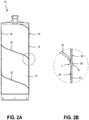
- FIGS. 2A , B shows a longitudinal section through the first drill bit 10 of FIG. 1 along the section line AA in FIG. 1B ( FIG. 2A ) and a detail of the drill shank 16 of the FIG. 2A in an enlarged view ( FIG. 2 B ).
- the spiral connection weld seam 32 projects beyond the shaped strip material 31 on an outer side 33 and an inner side 34 of the drill shaft 16.
- the supernatant of the spiral connection weld 32 on the outer side 33 of the drill shank 16 is referred to as outer projection ⁇ A and the supernatant of the spiral connection weld 32 on the inner side 34 of the drill shank 16 as inner projection ⁇ I.
- a suture 35 which provides the required volume of material is used in welding the formed strip material 31.
- the suture 35 may be powdered, wire-shaped or band-shaped.
- the material properties of the suture 35 may be adjusted to desired characteristics of the helical joint weld 32.
- the helical joint weld 32 when drilling with the first drill bit 10, improves the guidance of the drilling shank 18.
- the spiral connection weld 32 can be removed, thereby degrading the guidance of the drill shank 18.
- the properties of the spiral connection weld seam 32 can be influenced, so that the guidance of the drill shank 18 over the spiral connection weld seam 32 is ensured as far as possible during the entire service life of the drill shank 18.
- FIG. 3 shows a second embodiment of a drill bit 40 according to the invention , which is referred to below as the second drill bit 40.
- the second drill bit 40 comprises a drill shaft section 41, a receiving section 42 and a connecting device 43 which connects the drill shaft section 41 inseparably with the receiving section 42.
- the drill shank portion 41 comprises a helical drill shank 44 and a plurality of cutting segments 45 which are welded, brazed, glued, or otherwise secured to the drill shank 44 with the drill shank 44 .
- the receiving portion 42 includes a lid 46 and a spigot 47, via which the third drill bit 40 is mounted in a tool holder of a core drilling machine. In the drilling operation, the second drill bit 40 is driven by the core drill around a drilling axis 48 and moved in a drilling direction 49 parallel to the drilling axis 48 in the workpiece to be machined 23.
- the second drill bit 40 has a plurality of cutting segments 45, which are permanently attached to the drill shank 44.
- the second drill bit 40 may instead of a plurality of cutting segments 45 also have a single designed as a closed cutting ring cutting segment.
- the cutting segments 45 are welded, soldered, glued or otherwise secured to the drill shank 44 on the drill shank 44.
- the drill shank 44 is formed in a spiral tube shape in the form of a welded spiral tube, which was made of a strip material 51 in the form of a flat sheet with recesses by shaping and welding.
- the band material 51 was formed into a spiral tube and joined at the crimping band edges via a helical joint weld 52 .
- FIGS. 4A , B show a longitudinal section through the second drill bit 40 of the FIG. 3 along the section line AA in FIG. 3 ( FIG. 4A ) and a detail of the drill shank 46 of the FIG. 4A in an enlarged view ( FIG. 4B ).
- the spiral connection weld 52 of the drill shank 44 protrudes on an outer side 53 of the drill shank 44 with an outer projection ⁇ A opposite the shaped strip material 51 and is formed on an inner side 54 of the drill shank 44 substantially flush with the shaped strip material 51.
- a suture 55 is used in the welding of the shaped strip material 51 which provides the required volume of material.
- the suture 55 may be powder, wire or ribbon.
- the suture 55 may have the same material properties or different material properties as the band material 51.
- suture 55 and band material 51 have the same material properties, a uniform transition is created when the band edges are welded, and suture 55 can bond well with band material 51.
- the properties of the spiral connection weld 52 can be influenced so that the guidance of the drill stem 44 via the spiral connection weld seam 52 is possible during the entire service life of the drill stem 46 is guaranteed.
- the second drill bit 40 shows a spiral tubular drill stem 44 having a helical joint weld 52 projecting on the outside 53 of the drill stem 44 opposite the formed band material 51 and formed on the inside 54 of the drill stem 44 substantially flush with the formed band material 51.
- the helical joint weld 52 may protrude on the inner side 54 of the drill shank 44 with an inner projection ⁇ I opposite the formed strip material 51 and be formed on the outer side 53 of the drill shank 46 substantially flush with the formed strip material 51.
- a spiral connection weld 52 protruding on the inner side 54 of the drill shank 44, when drilling with the second drill bit 40, allows the drill shank 44 to be guided over the drill core 24.
- spiral connection weld 52 projecting on the inner side 54 can supply clean cooling and wet cutting during wet drilling Assist flushing fluid.
- the spiral connection weld 52 acts as a pumping coil for the clean cooling and rinsing liquid when the direction of rotation of the second drill bit 40 and the direction of the spiral connection weld 52 on the inside 54 of the drill shank 44 match.
- a cooling and rinsing liquid is required, which cools the cutting segments 45 as cooling liquid and removes cuttings from the borehole 25 as rinsing liquid.
- the protruding on the outer side 53 of the drill shank 44 spiral connection weld 52 can support the removal of cutted, spent cooling and flushing liquid in addition to the leadership of the drill shank 44 via the wellbore 25.
- the helical joint weld 52 acts as a delivery helix for the cutted, spent cooling and irrigation fluid when the direction of rotation of the second drill bit 40 and the direction of the spiral connection weld 52 on the outside 53 of the drill shank 44 match.
- three recesses 56A, 56B, 56C are arranged on the inner side 54 of the drill shank 44, which are referred to as first recess 56A, second recess 56B and third recess 56C.
- the recesses 56A, 56B, 56C are generated before the forming of the strip material 51 to the spiral tube in the sheet and are used in wet drilling with the second drill bit 40 as a transport channel for the necessary cooling and rinsing liquid.
- the recesses 56A, 56B, 56C are necessary above all with a small inner gap between the drill core and the drill shaft.
- the number of recesses 56A, 56B, 56C, the geometry of the recesses 56A, 56B, 56C and the arrangement of the recesses 56A, 56B, 56C on the outside 53 and / or inside 54 of the drill shank 44 can be adapted to the liquid quantity of the cooling and rinsing liquid ,
- the indentations 56A, 56B, 56C provided on the inside 54 of the drill shank 44 serve to supply clean cooling and rinsing liquid, and indentations provided on the outside 53 of the drill shank 44 can support the removal of cuttings, spent cooling and rinsing liquid. Since the recesses 56A, 56B, 56C are formed on the second drill bit 40 prior to forming the strip material 51, indentations can be made on the inside 54 of the drill stem 44 with little manufacturing effort.
- FIG. 5 shows a third embodiment of a drill bit 60 according to the invention , which is referred to below as the third drill bit 60.
- the third drill bit 60 comprises a drill shaft section 61, a receiving section 62 and a connection device 63 which connects the drill shaft section 61 inseparably with the receiving section 62.
- the drill shank portion 61 includes a helical drill shank 64 and a plurality of cutting segments 65 that are welded, brazed, glued or otherwise secured to the drill shank 64 by the drill shank 64 .
- the receiving portion 62 comprises a cover 66 and a spigot end 67, via which the third drill bit 60 is fastened in a tool holder of a core drilling apparatus. In the drilling operation, the third drill bit 60 is driven by the core drilling apparatus about a drilling axis 68 and moved in a drilling direction 69 parallel to the drilling axis 68 into the workpiece 23 to be machined.
- the third drill bit 60 has a plurality of cutting segments 65 which are permanently attached to the drill shaft 64.
- the third drill bit 60 may instead of a plurality of cutting segments 65 also have a single formed as a closed cutting ring cutting segment.
- the cutting segments 65 are welded, brazed, glued or otherwise secured to the drill shank 64 on the drill shank 64.
- the drill shaft 64 is formed as a welded spiral tube, which was made of a strip material 71 in the form of a wave-shaped profile sheet by forming and welding.
- the strip material 71 was formed into a spiral tube and joined at the crimping band edges via a helical joint weld 72 .
- the spiral connection weld seam 72 acts as a stiffening element for the drill shaft 64.
- FIGS. 6A , B show a longitudinal section through the third drill bit 60 of the FIG. 5 along the section line AA in FIG. 5 ( FIG. 6A ) and a detail of the drill shank 64 of FIG. 6A in an enlarged view ( FIG. 6B ).
- the spiral connection weld 72 of the drill shank 64 is formed on an outer side 73 of the drill shank 64 and on an inner side 74 of the drill shank 64 substantially flush with the shaped strip material 71.
- the recesses provided on the inner side 74 of the drill shank 64 serve to supply clean cooling and rinsing liquid and the depressions provided on the outer side 73 of the drill shank 64 for the removal of spent cooling and rinsing liquid offset with drill cuttings.
- the geometry of the profile sheet can be adapted to the amount of liquid required for wet drilling.
Abstract
Bohrkrone (10) zum Erstellen eines Bohrloches (25) mit einem Bohrlochdurchmesser (d2) und einem Bohrkern (24) mit einem Kerndurchmesser (d1) in einem Werkstück (23), aufweisend einen Bohrschaftabschnitt (11) mit einem rohrförmigen Bohrschaft (18), einen Aufnahmeabschnitt (12) mit einem Deckel (19) und einem Einsteckende (20) und eine Verbindungseinrichtung (13), die den Bohrschaftabschnitt (11) und Aufnahmeabschnitt (12) lösbar oder unlösbar miteinander verbindet, wobei der rohrförmige Bohrschaft (18) als geschweißtes Spiralrohr ausgebildet ist.

Description
Die vorliegende Erfindung betrifft eine Bohrkrone mit einem spiralrohrförmigen Bohrschaft gemäß dem Oberbegriff des Anspruchs 1 und ein Verfahren zur Herstellung eines spiralrohrförmigen Bohrschaftes für eine solche Bohrkrone gemäß dem Oberbegriff des Anspruchs 13.The present invention relates to a drill bit with a spiral-shaped drill shank according to the preamble of claim 1 and to a method for producing a spiral-shaped drill shank for such a drill bit according to the preamble of
Bohrkronen bestehen aus einem rohrförmigen Bohrschaft, einem Deckel, der den rohrförmigen Bohrschaft verschließt, und einem Einsteckende, über das die Bohrkrone in der Werkzeugaufnahme eines Kernbohrgerätes befestigt wird. Der Deckel und das Einsteckende sind Teile eines Aufnahmeabschnittes der Bohrkrone und der Bohrschaft ist Teil eines Bohrschaftabschnittes der Bohrkrone. Der Bohrschaftabschnitt und der Aufnahmeabschnitt sind mittels einer Verbindungseinrichtung lösbar oder unlösbar verbunden.Drill bits consist of a tubular drill shank, a lid which closes the tubular drill shank, and a shank end by which the drill bit is fastened in the tool holder of a core drill. The lid and the male end are parts of a receiving portion of the drill bit and the drill stem is part of a drill stem portion of the drill bit. The Bohrschaftabschnitt and the receiving portion are detachably or permanently connected by means of a connecting device.
Bei bekannten Bohrkronen werden feste Bohrkronen und Bohrkronen, die mit separaten Schneidabschnitten kombiniert werden können, unterschieden. Feste Bohrkronen weisen ein oder mehrere Schneidsegmente auf, die mit dem Bohrschaft unlösbar verbunden sind, wobei die Schneidsegmente am Bohrschaft verschweißt, verlötet, verklebt oder in einer anderen geeigneten Befestigungsart am Bohrschaft befestigt sind. Bei Bohrkronen, die mit separaten Schneidabschnitten kombiniert werden, sind die Schneidabschnitte über eine lösbare weitere Verbindungseinrichtung mit der Bohrkrone verbindbar. Die Schneidabschnitte umfassen einen Ringabschnitt und ein oder mehrere Schneidsegmente, die am Ringabschnitt befestigt sind.Known drill bits make a distinction between fixed drill bits and drill bits that can be combined with separate cutting sections. Fixed drill bits have one or more cutting segments that are non-detachably connected to the drill collar, wherein the cutting segments are welded, soldered, glued or fastened to the drill shaft in another suitable manner of attachment to the drill shaft. For drill bits that are combined with separate cutting sections, the cutting sections are connectable to the drill bit via a releasable additional connecting device. The cutting portions include a ring portion and one or more cutting segments attached to the ring portion.
Im Bohrbetrieb erzeugt eine Bohrkrone in einem Werkstück einen Bohrkern mit einem Kerndurchmesser und ein Bohrloch mit einem Bohrlochdurchmesser. Die Schneidsegmente bilden einen Schneidring mit einem Innendurchmesser, der dem Kerndurchmesser entspricht, und einem Außendurchmesser, der dem Bohrlochdurchmesser entspricht. Beim Bohren wird zwischen Nassbohren und Trockenbohren unterschieden. Bohrkronen zum Nassbohren (Nassbohrkronen) unterscheiden sich im Aufbau von Bohrkronen zum Trockenbohren (Trockenbohrkronen). Beim Nassbohren ist eine Kühl- und Spülflüssigkeit erforderlich, die als Kühlflüssigkeit die Schneidsegmente der Bohrkrone oder des Schneidabschnittes kühlt und als Spülflüssigkeit Bohrklein aus dem Bohrloch abtransportiert. Saubere Kühl- und Spülflüssigkeit wird in der Regel über einen Innenspalt zwischen dem Bohrkern und dem Bohrschaft zugeführt und mit Bohrklein versetzte, verbrauchte Kühl- und Spülflüssigkeit über einen Außenspalt zwischen dem Bohrschaft und dem Bohrloch abgeführt.In drilling operation, a drill bit in a workpiece produces a core diameter drill core and a bore diameter hole. The cutting segments form a cutting ring having an inner diameter corresponding to the core diameter and an outer diameter corresponding to the borehole diameter. When drilling a distinction between wet drilling and dry drilling. Drill bits for wet drilling (wet drill bits) differ in the construction of drill bits for dry drilling (dry drill bits). When wet drilling a cooling and rinsing liquid is required, which cools the cutting segments of the drill bit or the cutting section as cooling fluid and removed as drilling fluid cuttings from the well. Clean cooling and rinsing fluid is typically supplied through an inner gap between the core and the drill stem and discharged with cuttings, spent cooling and irrigation fluid through an outer gap between the drill shaft and the wellbore.
Bohrkronen, die sowohl einen Innenspalt zwischen Bohrkern und Bohrschaft als auch einen Außenspalt zwischen Bohrschaft und Bohrloch aufweisen, werden im Bohrbetrieb ausschließlich über die Schneidsegmente geführt, der gesamte Bohrschaft weist keine Führung auf. Die mangelnde Führung des Bohrschaftes kann während des Bohrens zu unerwünschten Bewegungen der Bohrkrone führen, die die Qualität des Bohrloches verschlechtern. Je stärker die Bewegungen der Bohrkrone sind, umso stärker kann die Geometrie des Bohrloches von der Kreisform abweichen. Außerdem können durch Krafteinwirkung des Bohrkerns oder des Bohrloches auf den Bohrschaft elastische Verformungen des Bohrschaftes auftreten.Drill bits, which have both an inner gap between the core and the drill stem and an outer gap between the drill stem and the drill hole are performed in drilling only on the cutting segments, the entire drill shaft has no guidance. The lack of guidance of the drill shank can lead to unwanted movements of the drill bit during drilling, which degrade the quality of the wellbore. The stronger the movements of the drill bit are, the more the geometry of the drill hole can deviate from the circular shape. In addition, by the action of force of the drill core or the borehole on the drill shank elastic deformations of the drill shank occur.
Um die Führung einer Bohrkrone zu verbessern, sind Bohrkronen ohne Innenspalt und/oder ohne Außenspalt bekannt, wobei die Kühl- und Spülflüssigkeit über spezielle Transportkanäle in der Außenseite des Bohrschaftes transportiert wird. Nachteilig ist, dass der Bohrschaft an der Innenseite eine große Kontaktfläche zum Bohrkern und an der Außenseite eine große Kontaktfläche zum Bohrloch aufweist. Die großen Kontaktflächen an der Innen- und Außenseite des Bohrschaftes führen zu einer starken Reibung. Je grösser die Reibung zwischen dem Bohrschaft und dem Bohrkern bzw. dem Bohrschaft und dem Bohrloch ist, umso geringer sind der Bohrfortschritt der Bohrkrone bei gleicher Leistung des Kernbohrgerätes und die Lebensdauer des Bohrschaftes.In order to improve the guidance of a drill bit, drill bits without inner gap and / or without outer gap are known, wherein the cooling and rinsing liquid is transported via special transport channels in the outside of the drill shaft. The disadvantage is that the drill shank on the inside has a large contact surface to the drill core and on the outside a large contact surface to the borehole. The large contact surfaces on the inside and outside of the drill stem lead to a strong friction. The greater the friction between the drill shank and the drill core or the drill shank and the drill hole, the lower the drilling progress of the drill bit with the same performance of the core drill and the life of the drill shank.
Die Aufgabe der vorliegenden Erfindung besteht darin, eine Bohrkrone dahingehend weiterzuentwickeln, dass die Stabilität und die Führung des Bohrschaftes beim Bohren, insbesondere beim Nassbohren mit einer Kühl- und Spülflüssigkeit, verbessert sind. Außerdem sollen der Bohrfortschritt der Bohrkrone erhöht und/oder die Lebensdauer des Bohrschaftes verlängert werden.The object of the present invention is to develop a drill bit to the effect that the stability and the leadership of the drill shank during drilling, especially when wet drilling with a cooling and rinsing liquid, are improved. In addition, the drilling progress of the drill bit to be increased and / or the life of the drill shaft to be extended.
Diese Aufgabe wird bei der eingangs genannten Bohrkrone erfindungsgemäß durch die Merkmale des unabhängigen Anspruchs 1 und bei dem eingangs genannten Verfahren erfindungsgemäß durch die Merkmale des unabhängigen Anspruchs 13 gelöst. Vorteilhafte Weiterbildungen sind in den abhängigen Ansprüchen angegeben.This object is achieved according to the invention in the aforementioned drill bit by the features of independent claim 1 and in the method mentioned above by the features of
Die Bohrkrone ist erfindungsgemäß dadurch gekennzeichnet, dass der rohrförmige Bohrschaft als geschweißtes Spiralrohr ausgebildet ist, wobei ein Bohrschaft, der als geschweißtes Spiralrohr ausgebildet ist, auch als spiralrohrförmiger Bohrschaft bezeichnet wird. Ein geschweißtes Spiralrohr weist mindestens eine spiralförmige Verbindungsschweißnaht auf, die für den Bohrschaft als Versteifungselement wirkt und die Steifigkeit des Bohrschaftes gegenüber einem längsnahtgeschweißten oder rohrförmigen Bohrschaft der gleichen Wandstärke erhöht. Alternativ können Bandmaterialien mit geringeren Wandstärken eingesetzt werden, die beim fertigen Bohrschaft die gleiche Steifigkeit wie ein längsnahtgeschweißter oder rohrförmiger Bohrschaft aufweisen. Damit erhöht die Verwendung eines geschweißten Spiralrohrs als Bohrschaft entweder die Steifigkeit des Bohrschaftes im Bohrbetrieb und/oder reduziert das Gewicht des Bohrschaftes. Ein Bohrschaft mit einer höheren Steifigkeit verbessert die Stabilität des Bohrschaftes beim Bohren.The drill bit according to the invention is characterized in that the tubular drill shaft is formed as a welded spiral tube, wherein a drill stem which is designed as a welded spiral tube, also referred to as a spiral tubular drill stem. A welded spiral tube has at least one spiral connection weld, which acts as a stiffening element for the drill shaft and increases the rigidity of the drill shaft with respect to a longitudinally welded or tubular drill shaft of the same wall thickness. Alternatively, band materials with lower wall thicknesses can be used which have the same rigidity in the finished drill stem as a longitudinally welded or tubular drill stem. Thus, the use of a welded spiral tube as a drilling shank either increases the rigidity of the drill shank in drilling operation and / or reduces the weight of the drill shank. A drill stem with a higher rigidity improves the stability of the drill shank during drilling.
Die erfindungsgemäße Bohrkrone weist einen Bohrschaftabschnitt mit dem spiralrohrförmigen Bohrschaft, einen Aufnahmeabschnitt mit einem Deckel und einem Einsteckende und eine Verbindungseinrichtung, die den Bohrschaftabschnitt und Aufnahmeabschnitt lösbar oder unlösbar miteinander verbindet, auf. Die Verbindungseinrichtung ist als lösbare oder unlösbare Verbindungseinrichtung ausgebildet. Eine Verbindungseinrichtung wird als lösbar bezeichnet, wenn die Verbindung vom Anwender zerstörungsfrei gelöst werden kann, wie beispielsweise eine Steckverbindung, eine Stiftverbindung oder eine Gewindeverbindung. Eine Verbindungseinrichtung wird als unlösbar bezeichnet, wenn der Anwender die Verbindung nur durch Zerstörung der Verbindungsmittel lösen kann, wie beispielsweise eine Lötverbindung, eine Schweißverbindung oder eine Klebeverbindung. Die Bohrkrone ist als feste Bohrkrone und als Bohrkrone, die mit separaten Schneidabschnitten kombiniert werden kann, ausgebildet. Die feste Bohrkrone weist ein oder mehrere Schneidsegmente auf, die mit dem Bohrschaft unlösbar verbunden sind, wobei die Schneidsegmente am Bohrschaft verschweißt, verlötet, verklebt oder in einer anderen geeigneten Befestigungsart am Bohrschaft befestigt sind. Bei einer Bohrkrone, die mit einem separaten Schneidabschnitt kombiniert wird, wird der Schneidabschnitt über eine lösbare Verbindungseinrichtung mit der Bohrkrone verbunden, wobei der Schneidabschnitt einen Ringabschnitt und ein oder mehrere Schneidsegmente, die am Ringabschnitt befestigt sind, umfasst.The drill bit according to the invention has a drill shaft section with the spiral-shaped drill shaft, a receiving section with a cover and a plug-in end, and a connection device which connects the drill shaft section and receiving section releasably or non-detachably. The connecting device is designed as a detachable or non-detachable connection device. A connection device is said to be detachable if the connection can be released non-destructively by the user, such as a plug connection, a pin connection or a threaded connection. A connection device is referred to as insoluble if the user can solve the connection only by destruction of the connecting means, such as a solder joint, a welded joint or an adhesive bond. The drill bit is designed as a solid drill bit and as a drill bit that can be combined with separate cutting sections. The fixed drill bit has one or more cutting segments that are non-detachably connected to the drill collar, the cutting segments being welded, soldered, glued or otherwise secured to the drill collar by the drill shaft. With a drill bit combined with a separate cutting portion, the cutting portion is connected to the drill bit via a releasable connection means, the cutting portion comprising a ring portion and one or more cutting segments attached to the ring portion.
Bevorzugt ist der rohrförmige Bohrschaft aus N, N ≥ 1 Bandmaterialen geformt, wobei die Bandkanten der Bandmaterialen über N, N ≥ 1 spiralförmige Verbindungsschweißnähte stoffschlüssig verbunden sind. Der Bohrschaft wird aus einem Bandmaterial (N = 1) oder mehreren Bandmaterialien (N ≥ 2) hergestellt, wobei die Anzahl der verwendeten Bandmaterialen der Anzahl der spiralförmigen Verbindungsschweißnähte entspricht. Bei der Herstellung der spiralrohrförmigen Bohrschäfte werden die Bandmaterialien in einer Formanlage spiralförmig mit gleichbleibendem Krümmungsradius kontinuierlich zu Spiralrohren geformt und in einer Schweißanlage an den Bandkanten verschweißt. Bei der Spiralrohrherstellung sind Verfahren in gemeinsamen Form- und Schweißanlagen und Verfahren in getrennten Form- und Schweißanlagen bekannt.Preferably, the tubular drill shank is formed from N, N ≥ 1 strip materials, wherein the strip edges of the strip materials via N, N ≥ 1 spiral connection welds are materially connected. The drill shank is made of a strip material (N = 1) or several strip materials (N ≥ 2), the number of strip materials used corresponding to the number of spiral joint welds. In the production of the spiral tubular drill shanks, the strip materials are in a molding plant Spiral shaped with constant radius of curvature continuously to spiral tubes and welded in a welding system at the strip edges. Spiral tube production involves processes in common forming and welding systems and processes in separate forming and welding plants.
In einer ersten Variante sind die N, N ≥ 1 Bandmaterialen als ebene Bleche mit einer konstanten Blechdicke ausgebildet. Der spiralrohrförmige Bohrschaft wird aus ebenen Blechen hergestellt, die eine konstante Blechdicke und eine konstante Breite aufweisen. Die ebenen Bleche werden zu einem Spiralrohr geformt und an den Bandkanten über spiralförmige Verbindungsschweißnähte miteinander stoffschlüssig verbunden. Das geformte Bandmaterial weist eine konstante Wandstärke auf, die der Blechdicke der ebenen Bleche entspricht. Die Geometrie der spiralförmigen Verbindungsschweißnähte kann durch die Prozessführung beim Schweißen beeinflusst werden. Durch die Zuführung eines Nahtmaterials können spiralförmige Verbindungsschweißnähte erzeugt werden, die an der Innenseite des Bohrschaftes, der Außenseite des Bohrschaftes oder an der Innen- und Außenseite des Bohrschaftes gegenüber dem geformten Bandmaterial überstehen.In a first variant, the N, N ≥ 1 strip materials are formed as flat sheets with a constant sheet thickness. The spiral tubular drill stem is made from flat sheets having a constant sheet thickness and a constant width. The flat sheets are formed into a spiral tube and connected cohesively to each other at the strip edges via spiral connection weld seams. The formed strip material has a constant wall thickness which corresponds to the sheet thickness of the flat sheets. The geometry of the spiral connection welds can be influenced by the process control during welding. By feeding a suture, spiral-shaped joint welds may be created that protrude from the inside of the drill stem, the outside of the drill stem, or the inside and outside of the drill stem opposite the formed band material.
In einer zweiten Variante sind die N, N ≥ 1 Bandmaterialen als ebene Bleche mit mindestens einer Vertiefung ausgebildet. Die Vertiefungen werden vor dem Umformen des Bandmaterials zum Spiralrohr im Blech erzeugt und dienen beim Nassbohren als Transportkanal für die notwendige Kühl- und Spülflüssigkeit. Beim Nassbohren mit einer Bohrkrone ist eine Kühlund Spülflüssigkeit erforderlich, die als Kühlflüssigkeit die Schneidsegmente kühlt und als Spülflüssigkeit Bohrklein aus dem Bohrloch abtransportiert. Die Anzahl der Vertiefungen, die Geometrie der Vertiefungen und die Anordnung der Vertiefungen auf der Innen- und/oder Außenseite des Bohrschaftes können an die Flüssigkeitsmenge der Kühl- und Spülflüssigkeit angepasst werden. Die an der Innenseite des Bohrschaftes vorgesehenen Vertiefungen dienen zur Zuführung von sauberer Kühl- und Spülflüssigkeit und die an der Außenseite des Bohrschaftes vorgesehenen Vertiefungen zur Abführung von mit Bohrklein versetzter, verbrauchter Kühl- und Spülflüssigkeit. Da die Vertiefungen bei der erfindungsgemäßen Bohrkrone vor dem Umformen des Bandmaterials erzeugt werden, können an der Innenseite des Bohrschaftes mit geringem Fertigungsaufwand Vertiefungen hergestellt werden. Bei bekannten Bohrschäften ist die Anordnung von Transportkanälen auf die Außenseite des Bohrschaftes beschränkt, da bei einem rohrförmigen Bohrschaft nur mit großem Fertigungsaufwand an der Innenseite des Bohrschaftes Vertiefungen hergestellt werden können.In a second variant, the N, N ≥ 1 strip materials are formed as flat sheets with at least one depression. The recesses are generated before forming the band material to the spiral tube in the sheet and are used during wet drilling as a transport channel for the necessary cooling and rinsing liquid. When wet drilling with a drill bit, a cooling and rinsing liquid is required, which cools the cutting segments as cooling fluid and removes cuttings from the borehole as rinsing fluid. The number of wells, the geometry of the wells and the arrangement of the wells on the inside and / or outside of the drill shank can be adapted to the liquid quantity of the cooling and rinsing liquid. The recesses provided on the inside of the drill shank serve to supply clean cooling and rinsing liquid and the depressions provided on the outside of the drill shank for the removal of spent cooling and rinsing liquid mixed with drill cuttings. Since the recesses are produced in the drill bit according to the invention prior to forming the strip material, depressions can be produced on the inside of the drill shank with little manufacturing effort. In known drilling shafts, the arrangement of transport channels is limited to the outside of the drill shank, since in a tubular drill shank indentations can be made only with great manufacturing effort on the inside of the drill shank.
In einer dritten Variante sind die N, N ≥ 1 Bandmaterialen als Profilbleche mit einem Profilquerschnitt ausgebildet, wobei die Profilbleche eine Blechdicke und eine Profilhöhe aufweisen. Der spiralrohrförmige Bohrschaft wird aus plattenförmigen Profilblechen hergestellt. Als Längsrichtung der plattenförmigen Profilbleche ist die Verlaufsrichtung des Profilquerschnitts definiert. Plattenförmige Profilbleche stehen kostengünstig in großer Anzahl mit unterschiedlichen Profilquerschnitten zur Verfügung und ermöglichen eine kostengünstige Herstellung von Bohrschäften für Bohrkronen. Durch den Profilquerschnitt entstehen an der Innen- und Außenseite des Bohrschaftes Vertiefungen, über die die Kühl- und Spülflüssigkeit transportiert werden kann. Die an der Innenseite des Bohrschaftes vorgesehenen Vertiefungen dienen zur Zuführung von sauberer Kühl- und Spülflüssigkeit und die an der Außenseite des Bohrschaftes vorgesehenen Vertiefungen zur Abführung von mit Bohrklein versetzter, verbrauchter Kühl- und Spülflüssigkeit. Die Geometrie des Profilblechs kann an die benötige Flüssigkeitsmenge der Kühl- und Spülflüssigkeit angepasst werden.In a third variant, the N, N ≥ 1 strip materials are formed as profile sheets with a profile cross-section, wherein the profile sheets have a sheet thickness and a profile height. The spiral tubular drill stem is made of plate-shaped profile sheets. When Longitudinal direction of the plate-shaped profile sheets, the course direction of the profile cross-section is defined. Plate-shaped profile sheets are available inexpensively in large numbers with different profile cross-sections and allow cost-effective production of drill shanks for drill bits. Due to the profile cross section, recesses are created on the inside and outside of the drill shaft, via which the cooling and rinsing fluid can be transported. The recesses provided on the inside of the drill shank serve to supply clean cooling and rinsing liquid and the depressions provided on the outside of the drill shank for the removal of spent cooling and rinsing liquid mixed with drill cuttings. The geometry of the profile sheet can be adapted to the required amount of liquid cooling and rinsing liquid.
In einer bevorzugten Weiterentwicklung der Bohrkrone steht mindestens eine spiralförmige Verbindungsschweißnaht des Bohrschaftes gegenüber dem geformten Bandmaterial des Spiralrohrs über, wobei die mindestens eine überstehende spiralförmige Verbindungsschweißnaht ein Nahtmaterial enthält. Eine gegenüber dem geformten Bandmaterial des Spiralrohrs überstehende spiralförmige Verbindungsschweißnaht verbessert die Führung des Bohrschaftes beim Bohren. Der Überstand der spiralförmigen Verbindungsschweißnaht wird so eingestellt, dass die spiralförmige Verbindungsschweißnaht an der Außenseite des Bohrschaftes mit dem Bohrloch und/oder an der Innenseite des Bohrschaftes mit dem Bohrkern in Kontakt steht. Durch die überstehende spiralförmige Verbindungsschweißnaht weist der Bohrschaft eine geringe Kontaktfläche zum Bohrkern und zum Bohrloch auf und erzeugt eine geringe Reibung. Je geringer die Reibung an der Innenseite zwischen Bohrschaft und Bohrkern bzw. an der Außenseite zwischen Bohrschaft und Bohrloch ist, umso grösser ist der Bohrfortschritt der Bohrkrone bei gleicher Leistung des Kernbohrgerätes und die Lebensdauer des Bohrschaftes ist erhöht. Die spiralförmige Verbindungsschweißnaht kann an einer Innenseite des Bohrschaftes, an einer Außenseite des Bohrschaftes oder an einer Innenund Außenseite des Bohrschaftes gegenüber dem geformten Bandmaterial des Spiralrohrs überstehen. Um einen Überstand der spiralförmigen Verbindungsschweißnaht zu erzeugen, ist ein Nahtmaterial erforderlich. Das Nahtmaterial kann drahtförmig, bandförmig oder pulverförmig ausgebildet sein.In a preferred further development of the drill bit, at least one spiral connection weld seam of the drill shaft projects beyond the shaped strip material of the spiral tube, wherein the at least one protruding spiral connection weld seam contains a suture. A spiral joint weld protruding from the formed strip material of the spiral tube improves the guidance of the drill stem during drilling. The supernatant of the helical joint weld is adjusted so that the helical joint weld on the outside of the drill shank contacts the wellbore and / or the inside of the drill shank with the core. Due to the protruding spiral connection weld, the drill shank has a small contact surface to the core and the borehole and generates a low friction. The lower the friction on the inside between the drill shank and core or on the outer side between the drill shaft and the hole, the greater the drilling progress of the drill bit with the same performance of the core drill and the life of the drill shank is increased. The helical joint weld may protrude to an inside of the drill stem, to an outside of the drill stem, or to an inside and outside of the drill stem opposite the formed band material of the spiral tube. To create a supernatant of the spiral joint weld, a suture is required. The suture may be wire-shaped, ribbon-shaped or powder-shaped.
Neben einer verbesserten Führung des Bohrschaftes beim Nass- und Trockenbohren kann eine gegenüber dem geformten Bandmaterial des Spiralrohrs überstehende spiralförmige Verbindungsschweißnaht beim Nassbohren den Transport der Kühl- und Spülflüssigkeit verbessern. Dabei wirkt die überstehende spiralförmige Verbindungsschweißnaht für die Kühlund Spülflüssigkeit als Förderwendel. Dabei ist zu beachten, dass die überstehende spiralförmige Verbindungsschweißnaht den Flüssigkeitstransport an der Innenseite oder der Außenseite des Bohrschaftes verbessern kann. An der Innenseite des Bohrschaftes wird saubere Kühl- und Spülflüssigkeit zur Bearbeitungsstelle transportiert und an der Außenseite des Bohrschaftes wird mit Bohrklein versetzte, verbrauchte Kühl- und Spülflüssigkeit abtransportiert. Die spiralförmige Verbindungsschweißnaht wirkt als Förderwendel für die saubere Kühl- und Spülflüssigkeit, wenn die Drehrichtung der Bohrkrone und die Verlaufsrichtung der spiralförmigen Verbindungsschweißnaht an der Innenseite des Bohrschaftes übereinstimmen, und die spiralförmige Verbindungsschweißnaht wirkt als Förderwendel für die mit Bohrklein versetzte, verbrauchte Kühl- und Spülflüssigkeit, wenn die Drehrichtung der Bohrkrone und die Verlaufsrichtung der spiralförmigen Verbindungsschweißnaht an der Außenseite des Bohrschaftes übereinstimmen.In addition to improved guidance of the drill shank in wet and dry drilling, a spiral connection weld projecting beyond the shaped strip material of the spiral tube can improve the transport of the cooling and rinsing liquid during wet drilling. The protruding spiral connection weld seam for the cooling and rinsing liquid acts as a conveyor spiral. It should be noted that the protruding helical joint weld can improve fluid transport on the inside or outside of the drill stem. On the inside of the drill shank is clean Cooling and rinsing liquid transported to the processing site and on the outside of the drill shank offset with cuttings, spent cooling and rinsing liquid is removed. The helical joint weld acts as a pumping coil for the clean cooling and irrigation fluid when the direction of rotation of the drill bit and the direction of the spiral connection weld on the inside of the drill shank match, and the spiral connection weld acts as a conveyor coil for the cutted, spent cooling and irrigation fluid when the direction of rotation of the drill bit and the direction of the spiral connection weld on the outside of the drill shaft match.
In einer bevorzugten Variante weisen das Nahtmaterial und die N, N ≥ 1 Bandmaterialen die gleichen Materialeigenschaften auf. Wenn das Nahtmaterial und die Bandmaterialien die gleichen Materialeigenschaften aufweisen, entsteht beim Schweißen der Bandkanten ein gleichmäßiger Übergang und das Nahtmaterial kann sich gut mit dem Bandmaterial verbinden.In a preferred variant, the suture and the N, N ≥ 1 strip materials have the same material properties. If the suture material and the band materials have the same material properties, a uniform transition will be created when the band edges are welded, and the suture may well bond to the band material.
In einer alternativen bevorzugten Variante weisen das Nahtmaterial und die N, N ≥ 1 Bandmaterialen unterschiedliche Materialeigenschaften auf, wobei das Nahtmaterial eine höhere Zugfestigkeit, eine höhere Verschleißbeständigkeit oder eine höhere Zugfestigkeit und Verschleißbeständigkeit als die Bandmaterialien aufweist. Bei einer spiralförmigen Verbindungsschweißnaht, die gegenüber dem geformten Bandmaterial übersteht, soll die Verbindungsschweißnaht während des Bohrbetriebs eine Führung des Bohrschaftes ermöglichen. Je kleiner der Spalt zwischen der spiralförmigen Verbindungsschweißnaht und dem Bohrkern an der Innenseite des Bohrschaftes bzw. zwischen der spiralförmigen Verbindungsschweißnaht und dem Bohrloch an der Außenseite ist, umso besser wird der Bohrschaft geführt. Durch Reibung zwischen der spiralförmigen Verbindungsschweißnaht und dem Bohrkern an der Innenseite bzw. zwischen der spiralförmigen Verbindungsschweißnaht und dem Bohrloch an der Außenseite kann die spiralförmige Verbindungsschweißnaht abgetragen werden, wodurch sich die Führung des Bohrschaftes verschlechtert. Durch den Einsatz von Nahtmaterial, das eine höhere Zugfestigkeit, eine höhere Verschleißbeständigkeit oder eine höhere Zugfestigkeit und Verschleißbeständigkeit als die Bandmaterialien aufweist, können die Eigenschaften der spiralförmigen Verbindungsschweißnaht beeinflusst werden, so dass die Führung des Bohrschaftes über die spiralförmige Verbindungsschweißnaht möglichst während der gesamten Lebensdauer des Bohrschaftes gewährleistet ist.In an alternative preferred variant, the suture and the N, N ≥ 1 band materials have different material properties, the suture having higher tensile strength, higher wear resistance, or higher tensile strength and wear resistance than the band materials. In a helical joint weld overlapping the formed strip material, the joint weld should allow for guidance of the drill stem during drilling operations. The smaller the gap between the helical joint weld and the core on the inside of the drill shank or between the helical joint weld and the outside hole, the better the drill shank is guided. By friction between the helical joint weld and the core on the inside or between the helical joint weld and the bore hole on the outside, the spiral joint weld can be removed, thereby degrading the guidance of the drill shank. The use of suture material having higher tensile strength, higher wear resistance or higher tensile strength and wear resistance than the band materials may influence the characteristics of the spiral joint weld so that the guidance of the drill stem through the spiral joint weld is maintained throughout the life of the joint Bohrschaftes is guaranteed.
In einer ersten bevorzugten Variante steht die mindestens eine überstehende spiralförmige Verbindungsschweißnaht an einer Innenseite des Bohrschaftes mit einem Innenüberstand ΔI gegenüber dem geformten Bandmaterial des Spiralrohrs über. Eine an der Innenseite des Bohrschaftes überstehende spiralförmige Verbindungsschweißnaht ermöglicht beim Bohren mit der Bohrkrone eine Führung des Bohrschaftes über den Bohrkern. Der Innenüberstand der spiralförmigen Verbindungsschweißnaht wird so eingestellt, dass die spiralförmige Verbindungsschweißnaht nach dem Anbohren der Bohrkrone an der Innenseite des Bohrschaftes mit dem Bohrkern in Kontakt steht. Außerdem kann eine an der Innenseite des Bohrschaftes überstehende spiralförmige Verbindungsschweißnaht beim Nassbohren mit der Bohrkrone den Transport der sauberen Kühl- und Spülflüssigkeit an die Bearbeitungsstelle unterstützen. Die spiralförmige Verbindungsschweißnaht wirkt als Förderwendel für die saubere Kühl- und Spülflüssigkeit, wenn die Drehrichtung der Bohrkrone und die Verlaufsrichtung der spiralförmigen Verbindungsschweißnaht an der Innenseite des Bohrschaftes übereinstimmen.In a first preferred variant, the at least one protruding spiral connection weld on an inner side of the drill shank overlaps an inner projection Δ I with respect to the shaped strip material of the spiral tube. One on the inside of the Drill shank protruding spiral connection weld allows drilling of the drill bit with a guide of the drill shank over the core. The inner overhang of the helical joint weld is adjusted so that the helical joint weld is in contact with the core after the drill bit is drilled on the inside of the drill shank. In addition, a spiral joint weld protruding from the inside of the drill stem when wet drilling with the drill bit can support the transport of the clean cooling and rinsing liquid to the processing site. The helical joint weld acts as a delivery helix for the clean coolant and irrigation fluid when the direction of rotation of the drill bit and the direction of the helical joint weld on the inside of the drill shank match.
In einer zweiten bevorzugten Variante steht die mindestens eine überstehende spiralförmige Verbindungsschweißnaht an einer Außenseite des Bohrschaftes mit einem Außenüberstand ΔA gegenüber dem geformten Bandmaterial des Spiralrohrs über. Eine an der Außenseite des Bohrschaftes überstehende spiralförmige Verbindungsschweißnaht ermöglicht beim Bohren mit der Bohrkrone eine Führung des Bohrschaftes über das Bohrloch. Der Außenüberstand der spiralförmigen Verbindungsschweißnaht wird so eingestellt, dass die spiralförmige Verbindungsschweißnaht nach dem Anbohren der Bohrkrone an der Außenseite des Bohrschaftes mit dem Bohrloch in Kontakt steht. Außerdem kann eine an der Außenseite des Bohrschaftes überstehende spiralförmige Verbindungsschweißnaht beim Nassbohren mit der Bohrkrone den Abtransport der mit Bohrklein versetzten, verbrauchten Kühl- und Spülflüssigkeit unterstützen. Die spiralförmige Verbindungsschweißnaht wirkt als Förderwendel für die mit Bohrklein versetzte, verbrauchte Kühl- und Spülflüssigkeit, wenn die Drehrichtung der Bohrkrone und die Verlaufsrichtung der spiralförmigen Verbindungsschweißnaht an der Außenseite des Bohrschaftes übereinstimmen.In a second preferred variant, the at least one protruding helical connecting weld on an outer side of the drill shank projects beyond an outer projection Δ A with respect to the shaped strip material of the spiral tube. A spiral joint weld projecting beyond the drill stem allows drilling of the drill bit over the well bore when drilling with the drill bit. The outer overhang of the helical joint weld is adjusted so that the helical joint weld is in contact with the borehole after the drill bit has been drilled on the outside of the drill stem. In addition, a protruding on the outside of the drill shank spiral connection weld during wet drilling with the drill bit support the removal of cutted, spent cooling and flushing liquid. The helical joint weld acts as a delivery helix for the cutted, spent cooling and irrigation fluid when the direction of rotation of the drill bit and the course of the helical joint weld on the outside of the drill stem coincide.
In einer dritten bevorzugten Variante steht die mindestens eine spiralförmige Verbindungsschweißnaht an einer Innenseite des Bohrschaftes mit einem Innenüberstand ΔI und an einer Außenseite des Bohrschaftes mit einem Außenüberstand ΔA gegenüber dem geformten Bandmaterial des Spiralrohrs über. Eine an der Innen- und Außenseite des Bohrschaftes überstehende spiralförmige Verbindungsschweißnaht ermöglicht beim Bohren mit der Bohrkrone eine Führung des Bohrschaftes sowohl an der Innenseite des Bohrschaftes über den Bohrkern als auch an der Außenseite des Bohrschaftes über das Bohrloch. Die an der Innenund Außenseite des Bohrschaftes überstehende spiralförmige Verbindungsschweißnaht wirkt beim Nassbohren an der Innenseite oder der Außenseite des Bohrschaftes als Förderwendel für die Kühl- und Spülflüssigkeit. Die Verlaufsrichtung der spiralförmigen Verbindungsschweißnaht legt fest, ob die spiralförmige Verbindungsschweißnaht den Flüssigkeitstransport an der Innen- oder Außenseite des Bohrschaftes unterstützt. Wenn die Verlaufsrichtung der spiralförmigen Verbindungsschweißnaht und die Drehrichtung der Bohrkrone an der Innenseite des Bohrschaftes übereinstimmen, unterstützt die spiralförmige Verbindungsschweißnaht den Flüssigkeitstransport an der Innenseite des Bohrschaftes. Wenn die Verlaufsrichtung der spiralförmigen Verbindungsschweißnaht und die Drehrichtung der Bohrkrone an der Außenseite des Bohrschaftes übereinstimmen, unterstützt die spiralförmige Verbindungsschweißnaht den Flüssigkeitstransport an der Außenseite des Bohrschaftes.In a third preferred variant, the at least one spiral connection weld on an inner side of the drill shank protrudes with an inner projection Δ I and on an outer side of the drill shank with an outer projection Δ A in relation to the shaped strip material of the spiral tube. A helical joint weld protruding on the inside and outside of the drill shank, when drilling with the drill bit, allows guidance of the drill shank both on the inside of the drill shank over the core and on the outside of the drill shank over the hole. The protruding on the inside and outside of the drill shank spiral connection weld acts during wet drilling on the inside or the outside of the drill shank as a conveyor coil for the cooling and rinsing liquid. The course of the spiral connection weld determines whether the spiral connection welds the liquid transport supported on the inside or outside of the drill shank. When the direction of the helical joint weld and the direction of rotation of the drill bit on the inside of the drill stem coincide, the helical joint weld assists in fluid transfer to the inside of the drill stem. When the direction of the helical joint weld and the direction of rotation of the drill bit coincide on the outside of the drill stem, the helical joint weld aids in fluid transport on the outside of the drill stem.
Erfindungsgemäß ist das Verfahren zur Herstellung eines Bohrschaftes für eine Bohrkrone nach einem der Ansprüche 1 bis 12, dadurch gekennzeichnet, dass die N, N ≥ 1 Bandmaterialien zu einem Spiralrohr geformt und an den Bandkanten über N, N ≥ 1 spiralförmige Verbindungsschweißnähte stoffschlüssig verbunden werden. Das erfindungsgemäße Verfahren ermöglicht eine kostengünstige Herstellung eines spiralrohrförmigen Bohrschaftes für eine Bohrkrone. Die Bandmaterialien werden in einer Formanlage schraubenlinienförmig mit gleichbleibendem Krümmungsradius kontinuierlich zu Spiralrohren geformt und in einer Schweißanlage an den Bandkanten verschweißt.According to the invention, the method for producing a drill shank for a drill bit according to one of claims 1 to 12, characterized in that the N, N ≥ 1 strip materials are formed into a spiral tube and bonded to the band edges via N, N ≥ 1 spiral connection welds. The method according to the invention enables a cost-effective production of a spiral-shaped drill shank for a drill bit. The strip materials are continuously formed in a mold system helically with constant radius of curvature to spiral tubes and welded in a welding system at the strip edges.
In einer bevorzugten Weiterentwicklung des Verfahrens wird beim Verbinden der zusammenstoßenden Bandkanten der N, N ≥ 1 Bandmaterialien über die N, N ≥ 1 spiralförmigen Verbindungsschweißnähte ein Nahtmaterial verwendet. Das Nahtmaterial ist beispielsweise drahtförmig, bandförmig oder pulverförmig ausgebildet und erzeugt eine gegenüber dem geformten Bandmaterial überstehende spiralförmige Verbindungsschweißnaht. Durch den Einsatz von Nahtmaterial beim stoffschlüssigen Verbinden der zusammenstoßenden Bandkanten können spiralförmige Verbindungsschweißnähte erzeugt werden, die gegenüber dem geformten Bandmaterial überstehen. Die überstehenden spiralförmigen Verbindungsschweißnähte führen den Bohrschaft beim Bohren an der Innenseite des Bohrschaftes über den Bohrkern und/oder an der Außenseite des Bohrschaftes über das Bohrloch. Die Geometrie der spiralförmigen Verbindungsschweißnähte kann über die Prozessführung beim Schweißen beeinflusst werden. Das Nahtmaterial kann der Innenseite des Bohrschaftes, der Außenseite des Bohrschaftes oder der Innen- und Außenseite des Bohrschaftes zugeführt werden.In a preferred further development of the method, a suture material is used in joining the abutting band edges of the N, N ≥ 1 band materials over the N, N ≥ 1 spiral-shaped joint welds. The suture is, for example, wire-shaped, band-shaped or powder-shaped and produces a helical joint weld protruding from the shaped band material. Through the use of suture material when joining the abutting band edges in a material-bonding manner, it is possible to produce spiral-shaped connection weld seams which project beyond the shaped band material. The protruding helical weld seams guide the drill stem over the wellbore during drilling on the inside of the drill shank over the core and / or on the outside of the drill shank. The geometry of the spiral connection welds can be influenced by the process control during welding. The suture may be delivered to the inside of the drill stem, the outside of the drill stem, or the inside and outside of the drill stem.
In einer besonders bevorzugten Variante des Verfahrens weist das Nahtmaterial eine höhere Zugfestigkeit, eine höhere Verschleißbeständigkeit oder eine höhere Zugfestigkeit und Verschleißbeständigkeit als die N, N ≥ 1 Bandmaterialien auf. Durch den Einsatz von Nahtmaterial, das eine höhere Zugfestigkeit, eine höhere Verschleißbeständigkeit oder eine höhere Zugfestigkeit und Verschleißbeständigkeit als die Bandmaterialien aufweist, können die Eigenschaften der spiralförmigen Verbindungsschweißnaht beeinflusst werden, so dass die Führung des Bohrschaftes über die spiralförmige Verbindungsschweißnaht möglichst während der gesamten Lebensdauer des Bohrschaftes gewährleistet ist.In a particularly preferred variant of the method, the suture has a higher tensile strength, a higher wear resistance or a higher tensile strength and wear resistance than the N, N ≥ 1 strip materials. The use of suture material having higher tensile strength, higher wear resistance, or higher tensile strength and wear resistance than the band materials may affect the characteristics of the spiral joint weld, so that the Guiding the drill shank on the spiral connection weld is guaranteed as long as possible throughout the life of the drill shank.
In einer alternativen besonders bevorzugten Variante des Verfahrens wird beim Verbinden der zusammenstoßenden Bandkanten der N, N ≥ 1 Bandmaterialien über die spiralförmigen Verbindungsschweißnähte ein erstes Nahtmaterial und ein zweites Nahtmaterial verwendet, wobei die Materialeigenschaften des ersten Nahtmaterials von den Materialeigenschaften des zweiten Nahtmaterials verschieden sind. Über die Materialeigenschaften des verwendeten Nahtmaterials lassen sich die Eigenschaften der spiralförmigen Verbindungsschweißnähte beeinflussen. Das erste Nahtmaterial kann beispielsweise die gleichen Materialeigenschaften wie die Bandmaterialien aufweisen, so dass beim Schweißen ein gleichmäßiger Übergang zwischen den Bandkanten entsteht und sich das erste Nahtmaterial gut mit dem Bandmaterial verbinden kann. Das zweite Nahtmaterial kann beispielsweise eine höhere Zugfestigkeit, eine höhere Verschleißbeständigkeit oder eine höhere Zugfestigkeit und Verschleißbeständigkeit als die Bandmaterialien aufweisen und die Eigenschaften der spiralförmigen Verbindungsschweißnähte verbessern.In an alternative, particularly preferred variant of the method, a first suture and a second suture are used in joining the abutting band edges of the N, N ≥ 1 band materials via the spiral joint welds, the material properties of the first suture being different from the material properties of the second suture. The properties of the spiral welds can be influenced by the material properties of the suture used. For example, the first suture may have the same material properties as the band materials, such that welding creates a smooth transition between the band edges and the first suture can bond well with the band material. For example, the second suture may have higher tensile strength, higher wear resistance, or higher tensile strength and wear resistance than the band materials and improve the characteristics of the spiral joint welds.
Ausführungsbeispiele der Erfindung werden nachfolgend anhand der Zeichnung beschrieben. Diese soll die Ausführungsbeispiele nicht notwendigerweise maßstäblich darstellen, vielmehr ist die Zeichnung, wo zur Erläuterung dienlich, in schematischer und/oder leicht verzerrter Form ausgeführt. Dabei ist zu berücksichtigen, dass vielfältige Modifikationen und Änderungen betreffend die Form und das Detail einer Ausführungsform vorgenommen werden können, ohne von der allgemeinen Idee der Erfindung abzuweichen. Die allgemeine Idee der Erfindung ist nicht beschränkt auf die exakte Form oder das Detail der im Folgenden gezeigten und beschriebenen bevorzugten Ausführungsform oder beschränkt auf einen Gegenstand, der eingeschränkt wäre im Vergleich zu dem in den Ansprüchen beanspruchten Gegenstand. Bei gegebenen Bemessungsbereichen sollen auch innerhalb der genannten Grenzen liegende Werte als Grenzwerte offenbart und beliebig einsetzbar und beanspruchbar sein. Der Einfachheit halber sind nachfolgend für identische oder ähnliche Teile oder Teile mit identischer oder ähnlicher Funktion gleiche Bezugszeichen verwendet.Embodiments of the invention are described below with reference to the drawing. This is not necessarily to scale the embodiments, but the drawing, where appropriate for explanation, executed in a schematic and / or slightly distorted form. It should be noted that various modifications and changes may be made in the form and detail of an embodiment without departing from the general idea of the invention. The general idea of the invention is not limited to the exact form or detail of the preferred embodiment shown and described below or limited to an article that would be limited in comparison with the subject matter claimed in the claims. For given design ranges, values lying within the specified limits should also be disclosed as limit values and be arbitrarily usable and claimable. For simplicity, the same reference numerals are used below for identical or similar parts or parts with identical or similar function.
Es zeigen:
- FIGN. 1A, B
- eine erste Ausführungsform einer erfindungsgemäßen Bohrkrone mit einem spiralrohrförmigen Bohrschaft, wobei die Bohrkrone mit einem separaten Schneidabschnitt verbindbar ist;
- FIGN. 2A, B
- einen Längsschnitt durch die Bohrkrone der
FIG. 1 entlang der Schnittlinie A-A inFIG. 1B (FIG. 2A ) sowie ein Detail des Bohrschaftes derFIG. 2A in einer vergrößerten Darstellung (FIG. 2B ); - FIG. 3
- eine zweite Ausführungsform einer erfindungsgemäßen Bohrkrone mit einem spiralrohrförmigen Bohrschaft, der mit mehreren Schneidsegmenten verbunden ist und an einer Innenseite drei Vertiefungen aufweist;
- FIGN. 4A, B
- einen Längsschnitt durch die Bohrkrone der
FIG. 3 entlang der Schnittlinie A-A inFIG. 3 (FIG. 4A ) sowie ein Detail des Bohrschaftes derFIG. 4A in einer vergrößerten Darstellung (FIG. 4B ); - FIG. 5
- eine dritte Ausführungsform einer erfindungsgemäßen Bohrkrone mit einem spiralrohrförmigen Bohrschaft, der mit mehreren Schneidsegmenten verbunden ist und aus einem Profilblech gefertigt wurde; und
- FIGN. 6A, B
- einen Längsschnitt durch die Bohrkrone der
FIG. 5 entlang der Schnittlinie A-A inFIG. 5 (FIG. 6A ) sowie ein Detail des Bohrschaftes derFIG. 6A in einer vergrößerten Darstellung (FIG. 6B ).
- FIGS. 1A, B
- a first embodiment of a drill bit according to the invention with a spiral-shaped drill shank, wherein the drill bit is connectable to a separate cutting section;
- FIGS. 2A, B
- a longitudinal section through the drill bit of
FIG. 1 along the section line AA inFIG. 1B (FIG. 2A ) as well as a detail of the drill shank of theFIG. 2A in an enlarged view (FIG. 2 B ); - FIG. 3
- a second embodiment of a drill bit according to the invention with a spiral tubular drill stem, which is connected to a plurality of cutting segments and having three recesses on an inner side;
- FIGS. 4A, B
- a longitudinal section through the drill bit of
FIG. 3 along the section line AA inFIG. 3 (FIG. 4A ) as well as a detail of the drill shank of theFIG. 4A in an enlarged view (FIG. 4B ); - FIG. 5
- a third embodiment of a drill bit according to the invention with a spiral tubular drill stem, which is connected to a plurality of cutting segments and was made of a profiled sheet; and
- FIGS. 6A, B
- a longitudinal section through the drill bit of
FIG. 5 along the section line AA inFIG. 5 (FIG. 6A ) as well as a detail of the drill shank of theFIG. 6A in an enlarged view (FIG. 6B ).
Der Schneidabschnitt 11 umfasst einen Ringabschnitt 16 und mehrere Schneidsegmente 17, die mit dem Ringabschnitt 16 verbunden sind. Die Schneidsegmente 17 werden ringförmig angeordnet und bilden einen Schneidring mit Zwischenräumen. Der Schneidabschnitt 14 kann anstatt mehrerer Schneidsegmente 17 auch ein einzelnes als geschlossener Schneidring ausgebildetes Schneidsegment aufweisen. Die Schneidsegmente 17 sind mit dem Ringabschnitt 16 verschweißt, verlötet, verklebt oder in einer anderen geeigneten Befestigungsart am Ringabschnitt 16 befestigt. Der Bohrschaftabschnitt 11 umfasst einen spiralrohrförmigen Bohrschaft 18 und der Aufnahmeabschnitt 12 umfasst einen Deckel 19 und ein Einsteckende 20, über das die erste Bohrkrone 10 in einer Werkzeugaufnahme eines Kernbohrgerätes befestigt wird. Im Bohrbetrieb wird die erste Bohrkrone 10 vom Kernbohrgerät um eine Bohrachse 21 angetrieben und in einer Bohrrichtung 22 parallel zur Bohrachse 21 in ein zu bearbeitendes Werkstück 23 bewegt. Die erste Bohrkrone 10 erzeugt im Werkstück 23 einen Bohrkern 24 mit einem Kerndurchmesser d1 und ein Bohrloch 25 mit einem Bohrlochdurchmesser d2. The cutting
Der Bohrschaft 18 ist als geschweißtes Spiralrohr ausgebildet, das aus einem Bandmaterial 31 in Form eines ebenen Blechs durch Formen und Schweißen gefertigt wurde. Das ebene Bandmaterial 31 wurde zu einem Spiralrohr geformt und an den zusammenstoßenden Bandkanten über eine spiralförmige Verbindungsschweißnaht 32 verbunden. Die spiralförmige Verbindungsschweißnaht 32 wirkt für den Bohrschaft 18 als Versteifungselement und erhöht die Steifigkeit des Bohrschaftes 18 gegenüber einem längsnahtgeschweißten oder rohrförmigen Bohrschaft der gleichen Wandstärke.The
Die spiralförmige Verbindungsschweißnaht 32 steht gegenüber dem geformten Bandmaterial 31 an einer Außenseite 33 und einer Innenseite 34 des Bohrschaftes 16 über. Der Überstand der spiralförmigen Verbindungsschweißnaht 32 an der Außenseite 33 des Bohrschaftes 16 wird als Außenüberstand ΔA und der Überstand der spiralförmigen Verbindungsschweißnaht 32 an der Innenseite 34 des Bohrschaftes 16 als Innenüberstand ΔI bezeichnet. Um die gegenüber dem geformten Bandmaterial 31 an der Außen- und Innenseite 33, 34 überstehende spiralförmige Verbindungsschweißnaht 32 zu erzeugen, wird beim Schweißen des geformten Bandmaterials 31 ein Nahtmaterial 35 verwendet, das das benötigte Materialvolumen zur Verfügung stellt. Das Nahtmaterial 35 kann pulverförmig, drahtförmig oder bandförmig ausgebildet sein. Außerdem können die Materialeigenschaften des Nahtmaterials 35 an gewünschte Eigenschaften der spiralförmigen Verbindungsschweißnaht 32 angepasst werden.The spiral
Die spiralförmige Verbindungsschweißnaht 32 verbessert beim Bohren mit der ersten Bohrkrone 10 die Führung des Bohrschaftes 18. Je kleiner der Spalt zwischen der spiralförmigen Verbindungsschweißnaht 32 und dem Bohrloch 25 an der Außenseite 33 bzw. zwischen der spiralförmigen Verbindungsschweißnaht 32 und dem Bohrkern 23 an der Innenseite 34 ist, umso besser wird der Bohrschaft 18 geführt. Durch Reibung zwischen der spiralförmigen Verbindungsschweißnaht 32 und dem Bohrloch 25 an der Außenseite 33 bzw. zwischen der spiralförmigen Verbindungsschweißnaht 32 und dem Bohrkern 24 an der Innenseite 34 kann die spiralförmige Verbindungsschweißnaht 32 abgetragen werden, wodurch sich die Führung des Bohrschaftes 18 verschlechtert. Durch den Einsatz von Nahtmaterial 35, das eine höhere Zugfestigkeit und Verschleißbeständigkeit als das Bandmaterial 31 aufweist, können die Eigenschaften der spiralförmigen Verbindungsschweißnaht 32 beeinflusst werden, so dass die Führung des Bohrschaftes 18 über die spiralförmige Verbindungsschweißnaht 32 möglichst während der gesamten Lebensdauer des Bohrschaftes 18 gewährleistet ist.The helical
Der Bohrschaftabschnitt 41 umfasst einen spiralrohrförmigen Bohrschaft 44 und mehrere Schneidsegmente 45, die mit dem Bohrschaft 44 verschweißt, verlötet, verklebt oder in einer anderen geeigneten Befestigungsart am Bohrschaft 44 befestigt sind. Der Aufnahmeabschnitt 42 umfasst einen Deckel 46 und ein Einsteckende 47, über das die dritte Bohrkrone 40 in einer Werkzeugaufnahme eines Kernbohrgerätes befestigt wird. Im Bohrbetrieb wird die zweite Bohrkrone 40 vom Kernbohrgerät um eine Bohrachse 48 angetrieben und in einer Bohrrichtung 49 parallel zur Bohrachse 48 in das zu bearbeitende Werkstück 23 bewegt.The
Die zweite Bohrkrone 40 weist mehrere Schneidsegmente 45 auf, die am Bohrschaft 44 unlösbar befestigt sind. Die zweite Bohrkrone 40 kann anstatt mehrerer Schneidsegmente 45 auch ein einzelnes als geschlossener Schneidring ausgebildetes Schneidsegment aufweisen. Die Schneidsegmente 45 werden am Bohrschaft 44 verschweißt, verlötet, verklebt oder in einer anderen geeigneten Befestigungsart am Bohrschaft 44 befestigt.The
Der Bohrschaft 44 ist spiralrohrförmig in Form eines geschweißten Spiralrohrs ausgebildet, das aus einem Bandmaterial 51 in Form eines ebenen Blechs mit Vertiefungen durch Formen und Schweißen gefertigt wurde. Das Bandmaterial 51 wurde zu einem Spiralrohr geformt und an den zusammenstoßenden Bandkanten über eine spiralförmige Verbindungsschweißnaht 52 verbunden.The
Die spiralförmige Verbindungsschweißnaht 52 des Bohrschaftes 44 steht an einer Außenseite 53 des Bohrschaftes 44 mit einem Außenüberstand ΔA gegenüber dem geformten Bandmaterial 51 über und ist an einer Innenseite 54 des Bohrschaftes 44 im Wesentlichen bündig mit dem geformten Bandmaterial 51 ausgebildet. Um die an der Außenseite 53 überstehende spiralförmige Verbindungsschweißnaht 52 zu erzeugen, wird beim Schweißen des geformten Bandmaterials 51 ein Nahtmaterial 55 verwendet, das das benötigte Materialvolumen zur Verfügung stellt.The
Das Nahtmaterial 55 kann pulverförmig, drahtförmig oder bandförmig ausgebildet sein. Über die Materialeigenschaften des Nahtmaterials 55 können die Eigenschaften der spiralförmigen Verbindungsschweißnaht 52 angepasst werden. Das Nahtmaterial 55 kann die gleichen Materialeigenschaften oder unterschiedliche Materialeigenschaften wie das Bandmaterial 51 aufweisen. Wenn Nahtmaterial 55 und Bandmaterial 51 die gleichen Materialeigenschaften aufweisen, entsteht beim Schweißen der Bandkanten ein gleichmäßiger Übergang und das Nahtmaterial 55 kann sich gut mit dem Bandmaterial 51 verbinden. Durch den Einsatz eines Nahtmaterials 55, das eine höhere Zugfestigkeit und/oder Verschleißbeständigkeit als das Bandmaterial 51 aufweist, können die Eigenschaften der spiralförmigen Verbindungsschweißnaht 52 beeinflusst werden, so dass die Führung des Bohrschaftes 44 über die spiralförmige Verbindungsschweißnaht 52 möglichst während der gesamten Lebensdauer des Bohrschaftes 46 gewährleistet ist.The suture 55 may be powder, wire or ribbon. By way of the material properties of the suture 55, the properties of the
Die zweite Bohrkrone 40 zeigt einen spiralrohrförmigen Bohrschaft 44 mit einer spiralförmigen Verbindungsschweißnaht 52, die an der Außenseite 53 des Bohrschaftes 44 gegenüber dem geformten Bandmaterial 51 übersteht und an der Innenseite 54 des Bohrschaftes 44 im Wesentlichen bündig mit dem geformten Bandmaterial 51 ausgebildet ist. Alternativ kann die spiralförmige Verbindungsschweißnaht 52 an der Innenseite 54 des Bohrschaftes 44 mit einem Innenüberstand ΔI gegenüber dem geformten Bandmaterial 51 überstehen und an der Außenseite 53 des Bohrschaftes 46 im Wesentlichen bündig mit dem geformten Bandmaterial 51 ausgebildet sein. Eine an der Innenseite 54 des Bohrschaftes 44 überstehende spiralförmige Verbindungsschweißnaht 52 ermöglicht beim Bohren mit der zweiten Bohrkrone 40 eine Führung des Bohrschaftes 44 über den Bohrkern 24. Außerdem kann die an der Innenseite 54 überstehende spiralförmige Verbindungsschweißnaht 52 beim Nassbohren die Zufuhr von sauberer Kühl- und Spülflüssigkeit unterstützen. Die spiralförmige Verbindungsschweißnaht 52 wirkt als Förderwendel für die saubere Kühl- und Spülflüssigkeit, wenn die Drehrichtung der zweiten Bohrkrone 40 und die Verlaufsrichtung der spiralförmigen Verbindungsschweißnaht 52 an der Innenseite 54 des Bohrschaftes 44 übereinstimmen.The
Beim Nassbohren mit der zweiten Bohrkrone 40 ist eine Kühl- und Spülflüssigkeit erforderlich, die als Kühlflüssigkeit die Schneidsegmente 45 kühlt und als Spülflüssigkeit Bohrklein aus dem Bohrloch 25 abtransportiert. Die an der Außenseite 53 des Bohrschaftes 44 überstehende spiralförmige Verbindungsschweißnaht 52 kann neben der Führung des Bohrschaftes 44 über das Bohrloch 25 den Abtransport von mit Bohrklein versetzter, verbrauchter Kühl- und Spülflüssigkeit unterstützen. Die spiralförmige Verbindungsschweißnaht 52 wirkt als Förderwendel für die mit Bohrklein versetzte, verbrauchte Kühl- und Spülflüssigkeit, wenn die Drehrichtung der zweiten Bohrkrone 40 und die Verlaufsrichtung der spiralförmigen Verbindungsschweißnaht 52 an der Außenseite 53 des Bohrschaftes 44 übereinstimmen.When wet drilling with the
Um saubere Kühl- und Spülflüssigkeit der Innenseite 54 des Bohrschaftes 44 zuzuführen, sind an der Innenseite 54 des Bohrschaftes 44 drei Vertiefungen 56A, 56B, 56C angeordnet, die als erste Vertiefung 56A, zweite Vertiefung 56B und dritte Vertiefung 56C bezeichnet werden. Die Vertiefungen 56A, 56B, 56C werden vor dem Umformen des Bandmaterials 51 zum Spiralrohr im Blech erzeugt und dienen beim Nassbohren mit der zweiten Bohrkrone 40 als Transportkanal für die notwendige Kühl- und Spülflüssigkeit. Die Vertiefungen 56A, 56B, 56C sind vor allem bei einem geringen Innenspalt zwischen dem Bohrkern und dem Bohrschaft notwendig. Die Anzahl der Vertiefungen 56A, 56B, 56C, die Geometrie der Vertiefungen 56A, 56B, 56C und die Anordnung der Vertiefungen 56A, 56B, 56C auf der Außenseite 53 und/oder Innenseite 54 des Bohrschaftes 44 können an die Flüssigkeitsmenge der Kühlund Spülflüssigkeit angepasst werden.In order to supply clean cooling and rinsing liquid to the
Die an der Innenseite 54 des Bohrschaftes 44 vorgesehenen Vertiefungen 56A, 56B, 56C dienen zur Zuführung von sauberer Kühl- und Spülflüssigkeit und an der Außenseite 53 des Bohrschaftes 44 vorgesehene Vertiefungen können den Abtransport von mit Bohrklein versetzter, verbrauchter Kühl- und Spülflüssigkeit unterstützen. Da die Vertiefungen 56A, 56B, 56C bei der zweiten Bohrkrone 40 vor dem Umformen des Bandmaterials 51 erzeugt werden, können an der Innenseite 54 des Bohrschaftes 44 mit geringem Fertigungsaufwand Vertiefungen hergestellt werden.The indentations 56A, 56B, 56C provided on the inside 54 of the
Der Bohrschaftabschnitt 61 umfasst einen spiralrohrförmigen Bohrschaft 64 und mehrere Schneidsegmente 65, die mit dem Bohrschaft 64 verschweißt, verlötet, verklebt oder in einer anderen geeigneten Befestigungsart am Bohrschaft 64 befestigt sind. Der Aufnahmeabschnitt 62 umfasst einen Deckel 66 und ein Einsteckende 67, über das die dritte Bohrkrone 60 in einer Werkzeugaufnahme eines Kernbohrgerätes befestigt wird. Im Bohrbetrieb wird die dritte Bohrkrone 60 vom Kernbohrgerät um eine Bohrachse 68 angetrieben und in einer Bohrrichtung 69 parallel zur Bohrachse 68 in das zu bearbeitende Werkstück 23 bewegt.The
Die dritte Bohrkrone 60 weist mehrere Schneidsegmente 65 auf, die am Bohrschaft 64 unlösbar befestigt sind. Die dritte Bohrkrone 60 kann anstatt mehrerer Schneidsegmente 65 auch ein einzelnes als geschlossener Schneidring ausgebildetes Schneidsegment aufweisen. Die Schneidsegmente 65 werden am Bohrschaft 64 verschweißt, verlötet, verklebt oder in einer anderen geeigneten Befestigungsart am Bohrschaft 64 befestigt.The
Der Bohrschaft 64 ist als geschweißtes Spiralrohr ausgebildet, das aus einem Bandmaterial 71 in Form eines wellenförmigen Profilblechs durch Formen und Schweißen gefertigt wurde. Das Bandmaterial 71 wurde zu einem Spiralrohr geformt und an den zusammenstoßenden Bandkanten über eine spiralförmige Verbindungsschweißnaht 72 verbunden. Die spiralförmige Verbindungsschweißnaht 72 wirkt für den Bohrschaft 64 als Versteifungselement.The
Die spiralförmige Verbindungsschweißnaht 72 des Bohrschaftes 64 ist an einer Außenseite 73 des Bohrschaftes 64 und an einer Innenseite 74 des Bohrschaftes 64 im Wesentlichen bündig mit dem geformten Bandmaterial 71 ausgebildet. Durch den Profilquerschnitt des Bandmaterials 71 entstehen an der Außenseite 73 und der Innenseite 74 des Bohrschaftes 66 Vertiefungen, über die beim Nassbohren mit der dritten Bohrkrone 60 Kühl- und Spülflüssigkeit transportiert werden kann. Die an der Innenseite 74 des Bohrschaftes 64 vorgesehenen Vertiefungen dienen zur Zuführung von sauberer Kühl- und Spülflüssigkeit und die an der Außenseite 73 des Bohrschaftes 64 vorgesehenen Vertiefungen zur Abführung von mit Bohrklein versetzter, verbrauchter Kühl- und Spülflüssigkeit. Die Geometrie des Profilblechs kann an die zum Nassbohren benötige Flüssigkeitsmenge angepasst werden.The
Claims (16)
Priority Applications (7)
| Application Number | Priority Date | Filing Date | Title |
|---|---|---|---|
| EP16206533.8A EP3338923A1 (en) | 2016-12-23 | 2016-12-23 | Annular drill bit with a spiral-shaped drill shaft and method for producing a spiral-shaped drill shaft for a drill bit |
| PCT/EP2017/080663 WO2018114240A1 (en) | 2016-12-23 | 2017-11-28 | Drill bit having a spiral-tube-shaped drill shaft and method for producing a spiral-tube-shaped drill shaft for a drill bit |
| US16/472,695 US20190366451A1 (en) | 2016-12-23 | 2017-11-28 | Drill Bit Having a Spiral-Tube-Shaped Drill Shaft and Method for Producing a Spiral-Tube-Shaped Drill Shaft for a Drill Bit |
| CN201780075239.7A CN110035854B (en) | 2016-12-23 | 2017-11-28 | Drill bit with a drill rod in the form of a spiral tube and method for producing a drill rod in the form of a spiral tube for a drill bit |
| JP2019534746A JP7039599B2 (en) | 2016-12-23 | 2017-11-28 | A method for manufacturing a core drill bit having a spiral tubular drill shaft and a spiral tubular drill shaft for a core drill bit. |
| EP17811884.0A EP3558574B1 (en) | 2016-12-23 | 2017-11-28 | Annular drill bit with a spiral-shaped drill shaft and method for producing a spiral-shaped drill shaft for a drill bit |
| KR1020197018566A KR102539883B1 (en) | 2016-12-23 | 2017-11-28 | Core bit having a spiral tube-shaped drill shank, and method for manufacturing the spiral tube-shaped drill shank for the core bit |
Applications Claiming Priority (1)
| Application Number | Priority Date | Filing Date | Title |
|---|---|---|---|
| EP16206533.8A EP3338923A1 (en) | 2016-12-23 | 2016-12-23 | Annular drill bit with a spiral-shaped drill shaft and method for producing a spiral-shaped drill shaft for a drill bit |
Publications (1)
| Publication Number | Publication Date |
|---|---|
| EP3338923A1 true EP3338923A1 (en) | 2018-06-27 |
Family
ID=57590406
Family Applications (2)
| Application Number | Title | Priority Date | Filing Date |
|---|---|---|---|
| EP16206533.8A Withdrawn EP3338923A1 (en) | 2016-12-23 | 2016-12-23 | Annular drill bit with a spiral-shaped drill shaft and method for producing a spiral-shaped drill shaft for a drill bit |
| EP17811884.0A Active EP3558574B1 (en) | 2016-12-23 | 2017-11-28 | Annular drill bit with a spiral-shaped drill shaft and method for producing a spiral-shaped drill shaft for a drill bit |
Family Applications After (1)
| Application Number | Title | Priority Date | Filing Date |
|---|---|---|---|
| EP17811884.0A Active EP3558574B1 (en) | 2016-12-23 | 2017-11-28 | Annular drill bit with a spiral-shaped drill shaft and method for producing a spiral-shaped drill shaft for a drill bit |
Country Status (6)
| Country | Link |
|---|---|
| US (1) | US20190366451A1 (en) |
| EP (2) | EP3338923A1 (en) |
| JP (1) | JP7039599B2 (en) |
| KR (1) | KR102539883B1 (en) |
| CN (1) | CN110035854B (en) |
| WO (1) | WO2018114240A1 (en) |
Families Citing this family (1)
| Publication number | Priority date | Publication date | Assignee | Title |
|---|---|---|---|---|
| US20210187626A1 (en) * | 2019-12-18 | 2021-06-24 | Decatur Diamond, Llc | Rotary cutting tool |
Citations (3)
| Publication number | Priority date | Publication date | Assignee | Title |
|---|---|---|---|---|
| US3025917A (en) * | 1959-06-11 | 1962-03-20 | Arthur W Knoblauch | Ice drill |
| EP2633931A2 (en) * | 2012-02-29 | 2013-09-04 | Robert Bosch Gmbh | Core drill bit |
| EP2745966A1 (en) * | 2012-12-21 | 2014-06-25 | HILTI Aktiengesellschaft | Annular drill bit with a replaceable cutting section |
Family Cites Families (18)
| Publication number | Priority date | Publication date | Assignee | Title |
|---|---|---|---|---|
| US921463A (en) * | 1908-07-28 | 1909-05-11 | Harry C Roberts | Spiral punch. |
| US1795380A (en) * | 1923-03-26 | 1931-03-10 | American Rolling Mill Co | Apparatus for making spiral tubing by electric welding |
| US3153885A (en) * | 1961-10-09 | 1964-10-27 | Chauncey A R Keller | Cyclindrical cutter device |
| US3797088A (en) * | 1972-09-08 | 1974-03-19 | Grotnes Machine Works Inc | Method of manufacturing cylindrical blanks |
| DE2520610C3 (en) * | 1975-05-09 | 1984-10-25 | Blohm + Voss Ag, 2000 Hamburg | Method and device for the production of screw sutures |
| GB1583860A (en) * | 1976-08-20 | 1981-02-04 | Moppes & Sons Ltd L Van | Core drills |
| JPH0118256Y2 (en) * | 1981-05-08 | 1989-05-29 | ||
| US4968101A (en) * | 1987-07-06 | 1990-11-06 | Bossow Emory R | Vertical asphalt and concrete miller |
| JPH03268874A (en) * | 1990-03-16 | 1991-11-29 | Kubota Corp | Manufacture of spiral steel pipe and edge preparation device |
| JPH08142039A (en) * | 1994-11-18 | 1996-06-04 | Hitachi Koki Co Ltd | Diamond core bit |
| EP0739673B1 (en) * | 1995-04-27 | 1998-12-23 | Hawera Probst GmbH + Co. | Tube for core drill |
| DE19648868A1 (en) * | 1996-11-26 | 1998-05-28 | Hilti Ag | Drilling tool with a hollow cylindrical support body |
| US10137507B2 (en) * | 2010-01-13 | 2018-11-27 | Irwin Industrial Tool Company | Hole cutter with multiple fulcrums |
| DE102011089546A1 (en) * | 2011-12-22 | 2013-06-27 | Hilti Aktiengesellschaft | Drill bit with a replaceable bit section |
| EP2745965A1 (en) * | 2012-12-21 | 2014-06-25 | HILTI Aktiengesellschaft | Annular drill bit with a replaceable cutting section |
| EP2745964A1 (en) * | 2012-12-21 | 2014-06-25 | HILTI Aktiengesellschaft | Cutting section |
| CA2855404C (en) * | 2013-07-02 | 2016-09-13 | Irwin Industrial Tool Company | Hole cutter |
| WO2016080869A1 (en) * | 2014-11-19 | 2016-05-26 | Kjell Andersson | Core drill with detachable end portion |
-
2016
- 2016-12-23 EP EP16206533.8A patent/EP3338923A1/en not_active Withdrawn
-
2017
- 2017-11-28 US US16/472,695 patent/US20190366451A1/en not_active Abandoned
- 2017-11-28 WO PCT/EP2017/080663 patent/WO2018114240A1/en unknown
- 2017-11-28 CN CN201780075239.7A patent/CN110035854B/en active Active
- 2017-11-28 KR KR1020197018566A patent/KR102539883B1/en active IP Right Grant
- 2017-11-28 JP JP2019534746A patent/JP7039599B2/en active Active
- 2017-11-28 EP EP17811884.0A patent/EP3558574B1/en active Active
Patent Citations (3)
| Publication number | Priority date | Publication date | Assignee | Title |
|---|---|---|---|---|
| US3025917A (en) * | 1959-06-11 | 1962-03-20 | Arthur W Knoblauch | Ice drill |
| EP2633931A2 (en) * | 2012-02-29 | 2013-09-04 | Robert Bosch Gmbh | Core drill bit |
| EP2745966A1 (en) * | 2012-12-21 | 2014-06-25 | HILTI Aktiengesellschaft | Annular drill bit with a replaceable cutting section |
Also Published As
| Publication number | Publication date |
|---|---|
| WO2018114240A1 (en) | 2018-06-28 |
| CN110035854A (en) | 2019-07-19 |
| US20190366451A1 (en) | 2019-12-05 |
| CN110035854B (en) | 2020-09-15 |
| KR102539883B1 (en) | 2023-06-02 |
| EP3558574B1 (en) | 2021-03-31 |
| KR20190100211A (en) | 2019-08-28 |
| JP7039599B2 (en) | 2022-03-22 |
| JP2020514584A (en) | 2020-05-21 |
| EP3558574A1 (en) | 2019-10-30 |
Similar Documents
| Publication | Publication Date | Title |
|---|---|---|
| DE102014207501B4 (en) | Rotary tool, in particular drill, and method for producing such a rotary tool | |
| DE102014105908B4 (en) | Tool for machining a workpiece and method for producing a tool | |
| DE102005034422B4 (en) | Reamer and process for its production | |
| EP2633931A2 (en) | Core drill bit | |
| EP1092494B1 (en) | Drilling method and apparatus for producing holes through overlapping elements | |
| DE10009732A1 (en) | Rock drill has drill head, spiral conveyor with main and subsidiary webs, conveyor edges, main and subsidiary cutter-blades. | |
| DE112008000158T5 (en) | Drill bit and single pass drill | |
| EP3558574B1 (en) | Annular drill bit with a spiral-shaped drill shaft and method for producing a spiral-shaped drill shaft for a drill bit | |
| DE102019211827B4 (en) | Drill and method of making a drill | |
| EP3558573B1 (en) | Trepanning drill bit with a spiral-shaped drill shaft and method for producing a spiral-shaped drill shaft for a drill bit | |
| DE102013210332A1 (en) | Cutting tool, in particular boring bar and method for machining a number of bores | |
| EP3558577B1 (en) | Method for producing a drill shaft for a wet trepanning drill bit | |
| WO2018114241A1 (en) | Method for producing a drill shaft for a drill bit | |
| EP3501714A1 (en) | Core bit with a helical guide element | |
| EP3501715A1 (en) | Core bit with a helical guide element | |
| DE102018007711A1 (en) | Manufacturing process for deep drilling tools | |
| DE2808655C2 (en) | Pipe connection | |
| WO2016116092A2 (en) | Dental instrument for the preparation of teeth, in particular tooth root channels, and pin for use in a provided hole, in particular a hole produced with a dental instrument according to the invention | |
| EP3501704A1 (en) | Method for producing a cutting section for a core bit | |
| EP1982787A1 (en) | Segment belt for drill bit and drill bit | |
| DE202013012695U1 (en) | Cutting tool, in particular boring bar | |
| EP3501703A1 (en) | Method for producing a cutting section for a core bit | |
| EP3501711A1 (en) | Method for producing a cutting section for a core bit | |
| WO2019120886A1 (en) | Method for producing a cutting section for a core bit | |
| EP3501706A1 (en) | Method for producing a cutting section for a core bit |
Legal Events
| Date | Code | Title | Description |
|---|---|---|---|
| PUAI | Public reference made under article 153(3) epc to a published international application that has entered the european phase |
Free format text: ORIGINAL CODE: 0009012 |
|
| AK | Designated contracting states |
Kind code of ref document: A1 Designated state(s): AL AT BE BG CH CY CZ DE DK EE ES FI FR GB GR HR HU IE IS IT LI LT LU LV MC MK MT NL NO PL PT RO RS SE SI SK SM TR |
|
| AX | Request for extension of the european patent |
Extension state: BA ME |
|
| STAA | Information on the status of an ep patent application or granted ep patent |
Free format text: STATUS: THE APPLICATION IS DEEMED TO BE WITHDRAWN |
|
| 18D | Application deemed to be withdrawn |
Effective date: 20190103 |