EP3338136B1 - Erweiterte realität in fahrzeugplattformen - Google Patents
Erweiterte realität in fahrzeugplattformen Download PDFInfo
- Publication number
- EP3338136B1 EP3338136B1 EP16832019.0A EP16832019A EP3338136B1 EP 3338136 B1 EP3338136 B1 EP 3338136B1 EP 16832019 A EP16832019 A EP 16832019A EP 3338136 B1 EP3338136 B1 EP 3338136B1
- Authority
- EP
- European Patent Office
- Prior art keywords
- vehicle
- real world
- virtual
- orientation
- camera
- Prior art date
- Legal status (The legal status is an assumption and is not a legal conclusion. Google has not performed a legal analysis and makes no representation as to the accuracy of the status listed.)
- Active
Links
Images


Classifications
-
- G—PHYSICS
- G06—COMPUTING OR CALCULATING; COUNTING
- G06T—IMAGE DATA PROCESSING OR GENERATION, IN GENERAL
- G06T19/00—Manipulating three-dimensional [3D] models or images for computer graphics
- G06T19/006—Mixed reality
-
- G—PHYSICS
- G06—COMPUTING OR CALCULATING; COUNTING
- G06F—ELECTRIC DIGITAL DATA PROCESSING
- G06F3/00—Input arrangements for transferring data to be processed into a form capable of being handled by the computer; Output arrangements for transferring data from processing unit to output unit, e.g. interface arrangements
- G06F3/01—Input arrangements or combined input and output arrangements for interaction between user and computer
- G06F3/011—Arrangements for interaction with the human body, e.g. for user immersion in virtual reality
-
- B—PERFORMING OPERATIONS; TRANSPORTING
- B60—VEHICLES IN GENERAL
- B60K—ARRANGEMENT OR MOUNTING OF PROPULSION UNITS OR OF TRANSMISSIONS IN VEHICLES; ARRANGEMENT OR MOUNTING OF PLURAL DIVERSE PRIME-MOVERS IN VEHICLES; AUXILIARY DRIVES FOR VEHICLES; INSTRUMENTATION OR DASHBOARDS FOR VEHICLES; ARRANGEMENTS IN CONNECTION WITH COOLING, AIR INTAKE, GAS EXHAUST OR FUEL SUPPLY OF PROPULSION UNITS IN VEHICLES
- B60K35/00—Instruments specially adapted for vehicles; Arrangement of instruments in or on vehicles
- B60K35/20—Output arrangements, i.e. from vehicle to user, associated with vehicle functions or specially adapted therefor
-
- B—PERFORMING OPERATIONS; TRANSPORTING
- B60—VEHICLES IN GENERAL
- B60K—ARRANGEMENT OR MOUNTING OF PROPULSION UNITS OR OF TRANSMISSIONS IN VEHICLES; ARRANGEMENT OR MOUNTING OF PLURAL DIVERSE PRIME-MOVERS IN VEHICLES; AUXILIARY DRIVES FOR VEHICLES; INSTRUMENTATION OR DASHBOARDS FOR VEHICLES; ARRANGEMENTS IN CONNECTION WITH COOLING, AIR INTAKE, GAS EXHAUST OR FUEL SUPPLY OF PROPULSION UNITS IN VEHICLES
- B60K35/00—Instruments specially adapted for vehicles; Arrangement of instruments in or on vehicles
- B60K35/80—Arrangements for controlling instruments
- B60K35/81—Arrangements for controlling instruments for controlling displays
-
- B—PERFORMING OPERATIONS; TRANSPORTING
- B60—VEHICLES IN GENERAL
- B60R—VEHICLES, VEHICLE FITTINGS, OR VEHICLE PARTS, NOT OTHERWISE PROVIDED FOR
- B60R11/00—Arrangements for holding or mounting articles, not otherwise provided for
- B60R11/04—Mounting of cameras operative during drive; Arrangement of controls thereof relative to the vehicle
-
- G—PHYSICS
- G02—OPTICS
- G02B—OPTICAL ELEMENTS, SYSTEMS OR APPARATUS
- G02B27/00—Optical systems or apparatus not provided for by any of the groups G02B1/00 - G02B26/00, G02B30/00
- G02B27/01—Head-up displays
-
- G—PHYSICS
- G06—COMPUTING OR CALCULATING; COUNTING
- G06T—IMAGE DATA PROCESSING OR GENERATION, IN GENERAL
- G06T11/00—Two-dimensional [2D] image generation
-
- B—PERFORMING OPERATIONS; TRANSPORTING
- B60—VEHICLES IN GENERAL
- B60R—VEHICLES, VEHICLE FITTINGS, OR VEHICLE PARTS, NOT OTHERWISE PROVIDED FOR
- B60R2300/00—Details of viewing arrangements using cameras and displays, specially adapted for use in a vehicle
- B60R2300/10—Details of viewing arrangements using cameras and displays, specially adapted for use in a vehicle characterised by the type of camera system used
- B60R2300/101—Details of viewing arrangements using cameras and displays, specially adapted for use in a vehicle characterised by the type of camera system used using cameras with adjustable capturing direction
-
- B—PERFORMING OPERATIONS; TRANSPORTING
- B60—VEHICLES IN GENERAL
- B60R—VEHICLES, VEHICLE FITTINGS, OR VEHICLE PARTS, NOT OTHERWISE PROVIDED FOR
- B60R2300/00—Details of viewing arrangements using cameras and displays, specially adapted for use in a vehicle
- B60R2300/10—Details of viewing arrangements using cameras and displays, specially adapted for use in a vehicle characterised by the type of camera system used
- B60R2300/105—Details of viewing arrangements using cameras and displays, specially adapted for use in a vehicle characterised by the type of camera system used using multiple cameras
-
- B—PERFORMING OPERATIONS; TRANSPORTING
- B60—VEHICLES IN GENERAL
- B60R—VEHICLES, VEHICLE FITTINGS, OR VEHICLE PARTS, NOT OTHERWISE PROVIDED FOR
- B60R2300/00—Details of viewing arrangements using cameras and displays, specially adapted for use in a vehicle
- B60R2300/30—Details of viewing arrangements using cameras and displays, specially adapted for use in a vehicle characterised by the type of image processing
- B60R2300/302—Details of viewing arrangements using cameras and displays, specially adapted for use in a vehicle characterised by the type of image processing combining image information with GPS information or vehicle data, e.g. vehicle speed, gyro, steering angle data
-
- B—PERFORMING OPERATIONS; TRANSPORTING
- B60—VEHICLES IN GENERAL
- B60R—VEHICLES, VEHICLE FITTINGS, OR VEHICLE PARTS, NOT OTHERWISE PROVIDED FOR
- B60R2300/00—Details of viewing arrangements using cameras and displays, specially adapted for use in a vehicle
- B60R2300/30—Details of viewing arrangements using cameras and displays, specially adapted for use in a vehicle characterised by the type of image processing
- B60R2300/304—Details of viewing arrangements using cameras and displays, specially adapted for use in a vehicle characterised by the type of image processing using merged images, e.g. merging camera image with stored images
-
- B—PERFORMING OPERATIONS; TRANSPORTING
- B60—VEHICLES IN GENERAL
- B60R—VEHICLES, VEHICLE FITTINGS, OR VEHICLE PARTS, NOT OTHERWISE PROVIDED FOR
- B60R2300/00—Details of viewing arrangements using cameras and displays, specially adapted for use in a vehicle
- B60R2300/50—Details of viewing arrangements using cameras and displays, specially adapted for use in a vehicle characterised by the display information being shared, e.g. external display, data transfer to other traffic participants or centralised traffic controller
Definitions
- Various embodiments are described herein that generally relate to creating an augmented reality world for viewing in vehicles using handheld or vehicle viewing devices.
- cameras attached to vehicles are intended to increase the vehicle driver's awareness of the surrounding obstacles and are intended for the purpose of safety. These cameras are typically facing or angled downwards, and they don't give a high level view of the surroundings of the vehicle; a high level view is meant to be a view that is directed towards the horizon. Additional cameras can be bought and used as dash cams to see a high level view of the vehicle's surroundings but the uses of these additional cameras have predominantly been for documenting events that occur outside of the vehicle. Therefore, these cameras are tailored for the driver's perspective and not for the vehicle passengers who may want to access to a view of the vehicle's surroundings which may include an Augmented Reality (AR) world which is a combination of real world surroundings and superimposed virtual reality objects. The augmented reality world may be of interest to the vehicle passengers for educational or entertainment purposes, also known as infotainment. Also most of these camera feeds are only streamed for viewing when the vehicle is stationary or when it is reversing to prevent the driver from distraction.
- AR Augmented Reality
- conventional AR viewing devices that are used for viewing augmented reality images or video streams such as cellphones, tablets, and wearable glasses, for example, each have a screen position that may be oriented in several ways.
- the physical location of these AR viewing devices may be determined mainly through the Global Positioning System (GPS).
- GPS Global Positioning System
- the orientation of the AR viewing devices may be obtained by using a gyroscope and a magnetometer, or a Simultaneous Localization and Mapping (SLAM) technique, or even using stationary 2D or 3D targets.
- SLAM Simultaneous Localization and Mapping
- the civilian GPS system when used by a user on foot for localization, has a radial error ranging from 10 meters to 30 meters. If the GPS data from the civilian GPS system is used to create an augmented world, then this error causes the augmented world viewpoint to suffer dramatically in precision.
- a gyroscope When a magnetometer is used for finding orientation, the accuracy has an error of between 10 to 35 degrees depending on the materials that are present in the surrounding environment. Also a gyroscope has errors in measurement of tilt (i.e. yaw, roll, and pitch) ranging from 20 to 70 degrees depending on the accuracy of the gyroscope. Moreover, a gyroscope shows a constant speed drift in yaw, roll, and pitch due to the nature of measurements.
- the 3D world map of a user's surroundings is constructed while the user is moving through the surroundings. This gives rise to the problem of the constructed real world getting defined relative to the initial camera state rather than actual global real world coordinates.
- this technique uses the spatial features around it to determine how the camera has moved relative to the initial direction the camera was facing. Accordingly, its orientation is defined relative to a local reference rather than the globe itself, which is limiting.
- any sudden camera movements may cause loss of tracking which might not be recoverable.
- the SLAM technique determines the orientation and location of the camera relative to the camera's original position by adding up differential vectors of the camera's movement. This leads to the accumulation of errors in measurement. In cases where a sudden change in position occurs, the error in measurement of the change may be so high that it may not be possible to determine the current position of the camera.
- US2009/125234A1 relates to a navigation device having a display for displaying a combination of a camera image and the navigation directions whereby the navigation directions are superimposed over the camera image by using pattern recognition techniques.
- US2014/168264A1 relates generally to using an electronic location post located outside a vehicle (e.g. fastened to a roof) and aligning an augmented reality device based on the electronic location post.
- EP2608153A1 relates to generating augmented reality in a motor vehicle using pattern recognition techniques for recognizing markers.
- US2012/038668A1 relates to controlling information on a mobile terminal and using information regarding movement of a pointer to generate the augmented reality information.
- US2015/202962A1 and US2013/286206A1 also relate to various techniques for generating augmented reality images using markers.
- US2014/134992A1 relates to managing usage of a mobile device and detecting optical data from an interior of a vehicle (including markers) and determining intra-vehicular location of the user in relation to the markers.
- US2013/002846A1 relates to a system for tracking the point of a gaze of an observer observing an object and using a marker to improve correspondence between the corneal reflection of the marker and the pupil centre.
- Closest prior art known from US2013/004920A1 relates to a method and simulator for training a crew member of a vehicle, especially a military vehicle, in the interior of the vehicle.
- a camera films the vehicle interior and is to be fixed to the head of the crew member.
- a display device is to be disposed in the field of view of the crew member and is to be fixed to the crew member's head.
- Via markers in the vehicle interior the position of a view is defined, and at the position of the view, a detail of a virtual vehicle external environment is overlaid in the display device as a function of the position and viewing direction of the crew member.
- Drawbacks of this system is that it uses inertial sensor unit for performing a measurement to obtain the relative direction of the markers to one another, but this system is unable to determine the orientation of the camera in relation to the real world.
- the present teaching provides an apparatus in accordance to appended independent claim 1, a method in accordance to appended independent claim 15 and a computer-readable medium in accordance to appended independent claim 16.
- Preferably embodiments are defined in the appended dependent claims 2-14.
- the embodiments described in accordance with the teachings herein generally relate to methodologies for creating an AR world comprising at least one AR image or an AR video stream in vehicles.
- the embodiments described herein may improve localization accuracy of the position of the user and therefore the accuracy for generating the AR world for the user by using the GPS unit associated with the vehicle.
- the embodiments described herein estimate the orientation of the on-board camera or mounted camera through which the AR dimension is going to be experienced.
- the embodiments described herein provide virtual content which is overlaid on top of the vehicle camera feed or the user's view of the surrounding real world.
- the virtual content may be graphical or it may be textual.
- graphical virtual content may include photos, graphics, animation, and the like.
- At least one of the embodiments described herein creates a parallel virtual world the content of which (e.g. 3D models and animations) is used to generate the AR images or AR video feed experienced by a user that uses an AR device to view the AR content, which may be a vehicle device such as an onboard vehicle display or a hand-held camera with a display or a wearable with a display.
- a vehicle device such as an onboard vehicle display or a hand-held camera with a display or a wearable with a display.
- At least one embodiment described herein enables the display of AR images or AR video feeds through AR device platforms such as, but not limited to, hand-held smart phones, tablets, laptops, and glasses with displays (transparent glasses or not), for example.
- AR device platforms such as, but not limited to, hand-held smart phones, tablets, laptops, and glasses with displays (transparent glasses or not), for example.
- a passenger of the vehicle operates cameras other than those that are used for the driver's needs in order to obtain real world data which are combined with one or more virtual objects to provide AR content.
- These cameras include, but are not limited to, one or more of an at least one interior vehicle camera, at least one onboard vehicle camera, at least one hand-held camera, and at least one exterior mounted vehicle camera, for example.
- Interior hand-held cameras as well as mounted cameras may be directed outside of the vehicle to a specific direction that the user wants.
- these cameras are calibrated so that their orientation will be measured relative to a vehicle reference point such as the vehicle's longitudinal axes.
- other axes of the vehicle may be used since the vehicle's orientation is known relative to the real world and the camera's orientation is known relative to the vehicle. In some cases, it is possible that the mounted cameras cover a 3D panoramic view of the outside of the vehicle for the convenience of the passengers.
- Examples of cameras that are used in one or more of the embodiments described in accordance with the teachings herein include, but are not limited to, one or more of at least one CCD camera, at least one
- CMOS camera at least one infrared camera, and at least one light field camera.
- an internal GPS module beside or inside the on-board display device such as a cell phone
- an external GPS module such as standalone GPS devices
- the orientation of the at least one mounted camera is measured and calibrated to generate accurate graphical renderings of the virtual world for overlaying or superimposing on one or more real world images obtained from the corresponding camera feed stream.
- the measurement and calibration may be done after the camera installation using techniques such as, but not limited to, structure from motion (SFM) or triangulation, in order to determine the orientation of the mounted cameras.
- SFM structure from motion
- the camera may be pointed at a 2D target or 3D target with a known orientation and location relative to the vehicle. Consequently, the camera's orientation may be determined relative to the target and relative to the vehicle as well.
- the contents or renderings of the virtual world is generated using various electronic devices such as, but not limited to, one or more of a cloud server, a device with a camera, a hand-held device, or a processing unit of the vehicle itself. If contents are produced by the cloud server in real-time, location data from the AR device within the vehicle may be communicated to the cloud server. In other cases, the virtual content is created in advance of being used by the AR vehicle device.
- the combination of the obtained virtual world image data with the at least one real world image data is done in the digital domain before displaying the at least one AR image on the display.
- the combination of the obtained virtual world data on the at least one real world image data occurs on the display as it is being viewed by the user.
- the location unit comprises a vehicle Global Positioning System (GPS) unit for determining the location information.
- GPS Global Positioning System
- the AR processing unit is configured to correct for GPS errors in the location information.
- the AR processing unit is provided by a server coupled to the vehicle by a wireless network.
- the AR processing unit is provided by one of a vehicle processing unit, a handheld device processing unit and a wearable device processing unit.
- the at least one marker comprises one or more of at least one 2D image marker and at least one 3D image marker.
- the at least one real world camera is mounted to the vehicle with a fixed orientation and calibration is performed to determine the orientation data when the at least one real world camera is first mounted and each time the orientation of the at least one real world camera is adjusted thereafter.
- the virtual content database includes one or more of at least one 3D virtual model, at least one 2D virtual image, at least one 3D virtual image on the arrangement of the virtual objects in the virtual world and virtual text information providing data about the virtual objects.
- the at least one real world camera is provided by a handheld device or a wearable device that is oriented relative to at least one image marker mounted to the vehicle based on the orientation of the at least one image marker relative to the vehicle and the orientation of the vehicle to a real world projection system.
- the at least one real world camera mounted on the vehicle is oriented during an installation and calibration stage relative to the vehicle and consequently oriented relative to a real world projection system based on the orientation of the vehicle relative to the real world projection system.
- the at least one real world camera is provided by one or more of at least one onboard vehicle camera, at least one camera mounted to a window of the vehicle, at least one handheld device and at least one wearable device.
- the at least one display is provided by one or more of at least one onboard vehicle display, at least one display, at least one handheld device and at least one wearable device.
- At least some of the elements of the various systems described herein that are implemented via software may be written in a high-level procedural language such as object oriented programming or a scripting language. Accordingly, the program code may be written in C, C ++ , Java, SQL or any other suitable programming language and may comprise modules or classes, as is known to those skilled in object oriented programming. It should also be understood that at least some of the elements of the various systems described herein that are implemented via software may be written in assembly language, machine language or firmware as needed.
- the program code can be stored on a storage media or on a computer readable medium that is readable by a general or special purpose programmable computing device having a processor, an operating system and the associated hardware and software that is necessary to implement the functionality of at least one of the embodiments described herein.
- the program code when read (i.e. when executed) by the computing device, configures the computing device to operate in a new, specific and predefined manner in order to perform at least one of the methods described herein.
- the computing devices that may be used in the various embodiments described herein generally include at least one processor, a data storage system (including volatile memory or non-volatile memory or other data storage elements or a combination thereof), and at least one communication interface.
- the programmable devices may be a server, a network appliance, an embedded device, a computer expansion module, a personal computer, a laptop, a personal data assistant, a cellular telephone, a smart-phone device, a tablet computer, a wireless device or any other computing device capable of being configured to carry out the methods described herein.
- the particular embodiment depends on the application of the computing device.
- a server can be used to provide a centralized database and/or a remote programming interface while an embedded device may be used for components that are worn or otherwise directly used by the user.
- the communication interface may be a network communication interface.
- the communication interface may be a software communication interface, such as those for inter-process communication (IPC).
- IPC inter-process communication
- there may be a combination of communication interfaces implemented as hardware, software, and a combination thereof.
- Program code may be applied to input data to perform at least some of the functions described herein and to generate output data.
- the output data may be applied to one or more output devices, as described herein to provide a new graphical visual experience for the user that was not possible with such accuracy and richness before.
- Any computer programs used by the systems described herein may be stored on a storage media or a device (e.g. ROM, magnetic disk, optical disc) readable by a general or special purpose programmable device, for configuring and operating the programmable device when the storage media or device is read by the programmable device to perform the procedures described herein.
- a storage media or a device e.g. ROM, magnetic disk, optical disc
- At least part of at least some of the embodiments described in accordance with the teachings herein may be considered to be implemented as a non-transitory computer-readable storage medium, having at least one computer program, where the computer program when executed by a computing device causes the computing device to operate in a specific and predefined manner to perform at least some of the functions described herein.
- some of the programs associated with the system, devices and methods of the embodiments described herein are capable of being distributed in a computer program product comprising a computer readable medium that bears computer usable instructions for execution by one or more processors.
- the medium may be provided in various forms, including non-transitory forms such as, but not limited to, one or more diskettes, compact disks, tapes, chips, and magnetic and electronic storage.
- the medium may be transitory in nature such as, but not limited to, wireline transmissions, satellite transmissions, internet transmissions (e.g. downloads), media, digital and analog signals, and the like.
- the computer useable instructions may also be in various formats, including compiled and non-compiled code.
- An image capture device refers to any device capable of recording visual information, and optionally digitizing this information as image data of one or more separate images or a stream of consecutive images that may be used as a video stream.
- image capture devices include, but are not limited to, digital camera devices, infrared camera devices, night vision cameras, UV cameras, and LIDAR devices.
- a display device refers to any device capable of rendering digital information in a visual manner.
- Some examples of display devices include, but are not limited to, wearable technology (e.g., Google glass, or other see through displays), display monitors (mobile or stationary), LED displays, and holographic display devices.
- An image capture and display device refers to devices that have the combined functionality of an image capture device and a display device.
- the AR device allows a user to view an augmented reality world.
- the AR device generally comprises a display that the user may watch or view.
- the AR device may include a mounted display mounted to a portion of a vehicle, a handheld display held by the user, or a display of a wearable such as glasses or a watch.
- real world refers to the world in which its elements (a.k.a. real objects) exist in isolation from virtual graphical content generated by computational devices for virtual objects that do not exist in the real world.
- a real world view of a downtown scene may include elements such as office buildings, stores and/or statues.
- real world data refers to data on the elements or real objects in the real world which are captured by an image capture device.
- virtual object refers to a virtual element which is used to construct the virtual world.
- a virtual object corresponds to a single object and virtual data may include one or more virtual objects.
- a virtual element may or may not directly correspond to a real world element.
- the virtual elements can be sensed by a user (e.g. through vision and/or sound) with the aid of an electronic display device and/or a speaker, which may also be a computational device, such as the AR device.
- a virtual object may comprise text or visual information for a real world object such as at least one of a name, a year of construction and height of an office building.
- a virtual object may be an image of a real object at a certain point in time, such as in the past when the real object looked different (e.g. perhaps the real object is now degraded due to age and wear and the virtual object shows the real object as it appeared when it was first made or at another point in time or before it started to deteriorate) or perhaps in the future showing modifications that may be made to the real object.
- virtual world data refers to digital data and content representing virtual objects in the real world.
- Examples of virtual world data may include, but is not limited to, 3D model data of objects for generating 3D virtual objects that can be included in one or more AR images.
- Other examples of virtual world data include one or more of 3D text, 2D images, 3D animation, 2D animation and other graphics.
- vehicle refers to any transportation means or any compartment that is able to move to different locations or rotate in the real world.
- vehicles include, but are not limited to, cars, buses, trucks, bikes, motor-bikes, motorcycles, trains, trams, street-cars, airplanes, balloons, helicopters, quad-copters, drones, ships, boats, submarines, and spacecraft.
- virtual world camera is a camera which captures a view of the virtual world to produce virtual world data.
- Virtual image data of virtual world data from the virtual world camera may be overlaid on top of real image data of real world data from the real world to create AR image data from which an AR image can be obtained for display to the user.
- a virtual video data stream of virtual world data from the virtual world camera may be overlaid on top of a real video data stream of real world data from the real world to create an AR data stream from which a series of AR images can be obtained for display to the user.
- the virtual world data stream may be shown on the transparent display.
- the virtual world camera may be generated and modified to follow the movement of the camera used in the vehicle to obtain the real world data (this camera in the vehicle may be a vehicle camera, a hand-held camera for a handheld being used by the passenger or a wearable camera for a wearable being worn by the user).
- the movement can be followed by generating a virtual location, virtual orientation and virtual field of view for the virtual world camera that is the same as the location, orientation and field of view of the real world camera.
- there may be one or more real world cameras that each have their own location, orientation and field of view there can be one or more corresponding virtual world cameras with a corresponding location, orientation and field of view.
- various embodiments are described for providing Augmented Reality (AR) world viewing arrangements in vehicles to permit the passengers to view an overlay of a virtual digital world onto their surroundings.
- the various embodiments generally utilize geo-location devices and systems combined with digital content to provide an overlay of a different reality and to bring real and virtual viewing perspectives into correlation with one another to account for the viewing angle.
- left and/or right video cameras may be mounted on the left and/or right sides, respectively, of a vehicle facing the away from the left and/or right side, respectively, of the vehicle.
- Each video camera generally has a miniature video camera viewing angle that is directed generally side-wards, and can be housed inside the vehicle, or on the inside of a passenger window and directed towards the outside of the vehicle which will protect it from outside conditions.
- the real world viewed through these cameras can be combined with the content (e.g. graphics of text) of at least one virtual object in a corresponding virtual world to provide an AR world.
- the AR world viewed from these perspectives can be displayed on any screen or display generally inside the vehicle including, but not limited to, hand held displays, virtual glasses, embedded back-seat monitors, and holographic displays for viewing by a passenger of the vehicle. The passengers then can easily observe the AR world from the perspective of a real world camera with a known orientation in space.
- the virtual world data can be downloaded and rendered using embedded hardware in the vehicle as will be described.
- a passenger (a.k.a. a user) may be using a camera which is either held in the user's hand or is embedded in a wearable technology device that is worn by the user.
- the outside world will be seen through the lenses of the real world camera worn/held by the user within the vehicle.
- virtual world data may be overlaid or otherwise combined with the real world data that is obtained using the real world camera.
- the virtual content used for the virtual object data may be generated on a remote server (e.g. a cloud server) and sent to the passenger device for combination with the real world data.
- the real world data and virtual world data can be combined at the remote server and send to the AR device for viewing.
- the user may be holding/wearing a device with a camera but the virtual content is rendered on the device with the camera itself.
- the data required for this rendering can be preloaded or it can be imported from the server in real-time to the handheld/wearable device.
- the server contains virtual world data including data on virtual objects and data on their placement within the virtual world.
- the embodiments described in accordance with the teachings herein generally enable virtual world data to be overlaid with real world data to generate AR data without the current errors that exist with conventional AR devices because an alignment is provided since the location of the real world camera is known with accuracy and is used to place virtual objects in the AR world at a virtual position that corresponds to their proper location in reality (i.e. the "real world location").
- a parallel world may then be generated which can be experienced in the embedded platform of a vehicle or through a handheld or wearable camera within the vehicle.
- this technology may be used by passengers, which will not cause any driving hazards as the AR images do not have to be viewed by the driver.
- FIG. 1 shown therein is a block diagram of an example embodiment of an AR system 10 that may be used to generate at least one AR image for viewing by an individual or a user 182 in a vehicle.
- the AR system 10 allows the user to experience an AR world in the vehicle of at least a portion of the surroundings of the vehicle.
- the AR system 10 comprises an AR device 184 that generally interacts with embedded devices 186 for visualization of augmented reality world, at least one of the location elements 188 for locating the AR device 184 relative to the real world, at least one of the orienting elements 190 for orienting the cameras used by the AR device 184 with respect to the real world, and at least one location based application 191 which have been integrated into the AR system 10 for enabling such experience as well communicating through a network 200.
- the AR system 10 further comprises a virtual content database 196 comprising virtual world data.
- the virtual content database 196 may be provided by an onboard vehicle device, by a handheld or wearable device or by a networked server, depending on the particular implementation.
- the embedded devices 186 may include a collection of input/output devices which a vehicle passenger (a.k.a. the user) interacts with to view various images of an AR world and optionally to also interact with the AR world.
- the user can interact with the AR world through voice commands that are received by the microphone of the AR device 184, hand gestures that are detected by RGB and depth cameras of the AR device 184, handheld control devices and other suitable input devices for the AR device 184.
- the user can interact with the AR world by performing various actions including, but not limited to, placement of virtual content into the virtual world, receiving data about the virtual objects, and gamification with virtual objects in the manner of shooting games.
- the AR viewing application 191 may receive input data from the user and make changes to the virtual content of the virtual world that correspond to the user's input data.
- the embedded devices 186 generally include at least one display 186-1 to allow the passenger(s) to view at least one AR image (e.g. the virtual world superimposed on the real world) and/or to view virtual objects.
- the at least one display 186-1 may include, but is not limited to, at least one of see-through displays, screens, eye glass screens, onboard vehicle monitors and contact lens displays.
- the embedded devices generally include at least one real world camera 186-2 for obtaining at least one real world image of a portion of the vehicle surroundings.
- the at least one real world camera 186-2 may be used as a receiver of the real world data.
- the at least one real world camera 186-2 may also be used with a tracking marker to help orient the at least one real world camera.
- Examples of the at least one real world camera 186-2 may include but, is not limited to, Red-Green-Blue (RGB) cameras, Lidar cameras, Lytro cameras, depth sensor cameras, time of flight cameras, and ultrasound cameras.
- RGB Red-Green-Blue
- the embedded devices 186 may also include audio components 186-3 which may be a device through which an audio command may be received from the user.
- the audio components 186-3 include at least one microphone.
- the audio components 186-3 may be used for communicating information to the user about the AR world images that are being shown to the user as well as other information.
- the audio components 186-3 include at least one speaker.
- the audio components 186-3 include at least one microphone and at least one speaker. However, including a microphone may be optional in some embodiments depending on the desired user AR experience.
- the location unit 188 includes one or more location units that are used for locating the user in the real world by determining location data for the location of the at least one real world camera.
- These location units can include, but are not limited to, at least one of a Global positioning systems (GPS) unit 188-1 for obtaining the location data using satellites, a cellular tower reception positioning unit 188-2, a WiFi networks positioning unit 188-3, and a surrounding video positioning unit 188-4 via processing a video stream from the vehicle's surrounding.
- GPS Global positioning systems
- the cellular tower reception positioning unit 188-2 and the WiFi networks positioning unit 188-3 can use triangulation techniques that are known by those skilled in the art to obtain the location data.
- the location data provided by these devices is used to estimate at least one of the location of the user, the location of the user's display device, or the location of the vehicle in the real world. Although there are four location elements shown in FIG. 1 , other subsets of these devices, including just one of these devices, may be used in certain embodiments.
- the GPS unit 188-1 is used for determining the location of the user's display device in the real world relative to the earth.
- the GPS unit 188-1 may be embedded in the display device hardware 186-1 or may be used as an external device that communicates with the AR device 184.
- the GPS positioning errors can be reduced.
- the GPS positioning error can be reduced to a one dimensional error. For example, if the vehicle has an internal GPS module, then its data may be used as vehicles have more accurate GPS modules embedded in them than hand held devices or wearable technologies do.
- the radial uncertainty which is associated with the user using a GPS module may be collapsed to a linear uncertainty, the error which can be better corrected since the vehicle has a well-defined pattern of movement along a given travel route most of the time.
- This may be done by projecting the GPS data onto the travel route to be taken by the vehicle, which is a collection of 1D line segments. This projection may be done, for example, by finding the closest point on the route to be taken to the new GPS point acquired.
- factors such as, but not limited to, speed and acceleration of the vehicle may be estimated for capturing the vehicle's pattern of movement over the route.
- the GPS error is collapsed into a 1D error.
- the error of the projected upcoming GPS data may also be decreased.
- the cellular tower reception position system 188-2 may be used for determining the location of the user's vehicle or the user's AR device 184 in the real world.
- the positioning may be done through the signals acquired from multiple cell-towers. This type of positioning may be used in conjunction with other positioning methods such as GPS, for example, as is known by those skilled in the art.
- the Wi-Fi networks unit 188-3 is used to determine the location of the vehicle or the user's AR device 184 within the real world. The positioning may be done through the received Wi-Fi signals in the vicinity of the vehicle. Multiple WiFi resources may be used for this positioning. WiFi network positioning may also be used with other positioning methods such as, but not limited to, GPS and cellular tower reception positioning, as is known by those skilled in the art. As multiple sensors for positioning are used to each provide location data, the location data can be combined and the accuracy of the location data is increased.
- the surrounding video positioning device 188-4 may be used for determining the location of the user within the real world. Positioning using surrounding video processing may be done through performing image processing techniques on the vehicle's surroundings for matching one or more images from the real world camera with already known views (i.e. images) of the real world. For example, this may be done by comparison of previously taken real world images from repositories, such as Google street view, and the real world image data that is captured in real-time during use.
- the obtained images from the real world camera may include, but are not limited to, infra-red images, RGB images, ultrasound images, LIDAR images, as well as time-of-flight images.
- the orientation unit 190 includes devices that may be used for locating and orienting the camera 186-2 of the user's AR device 184 relative to the vehicle or the surrounding environment and providing orientation data for the camera 186-2. Examples of such devices include, but are not limited to, a 2D marker tracker 190-1, a 3D marker tracker 190-2, and a relative environment positioning device 190-3 for providing orientation data relative to the surrounding environment.
- the 2D marker tracker 190-1 may be used for obtaining orientation data on the orientation of the real world image capture device (e.g. a handheld or a wearable camera) relative to the vehicle.
- the 2D marker tracker 190-1 may achieve this by orienting the image capturing device (e.g. camera 186-2) relative to a 2D image marker attached on the vehicle which has an orientation and a location that is known relative to the vehicle.
- Examples of 2D image markers may include, but are not limited to, one or more of a printed image on a paper, and a displayed 2D image on a flat 2D screen.
- These 2D image markers may be tracked using cameras 186-2 embedded in the AR device 184 which may include but is not limited to one or more of at least one RGB camera, at least one infrared camera, at least one ultrasound camera, at least one LIDAR camera, and at least one time of flight camera.
- An example of image capturing device orienting techniques may include but is not limited to, structure from motion (SFM).
- SFM structure from motion
- the 3D marker tracker 190-2 may be used for obtaining orientation data for the orientation of the image capture device relative to the vehicle. This may be achieved by orienting the image capturing device relative to a 3D marker that is attached on the vehicle and has an orientation and a location that is known relative to the vehicle.
- 3D markers may include, but are not limited to, a printed image of an object such as a cube, and a 3D object with or without texture such as a toy car.
- the 3D image markers may be tracked using cameras 186-2 embedded on the AR device 184 which may include, but are not limited to, one or more of at least one RGB camera, at least one infrared camera, at least one ultrasound camera, at least one LIDAR camera, and at least one time of flight camera.
- An example of image capturing device orienting techniques includes, but is not limited to, structure from motion (SFM).
- SFM structure from motion
- the relative environment positioning unit 190-3 may be used for orienting the real world camera 186-2 relative to the real world.
- This unit 190-3 may achieve this by comparison of the real world video stream (i.e. stream of image data) with known world images of the vehicle's surroundings and measure the orientation of the camera 186-2 of the AR device 184 and provide orientation data using techniques such as, but not limited to structure from motion. Accordingly, the SFM technique can be used for obtaining both location data and orientation data for the real world camera 186-2 relative to the surrounding environment.
- a creator 193 may create virtual world data and may place this data in his/her desired location. Input from the creator 193 may be received and will be used for construction of the virtual world.
- the creator can be a passenger of the vehicle as well as a user, such as a system administration using his computer at a remote location. These users can contribute to the creation of the virtual world through a website or through the AR viewing application 191.
- the processing device 194 is optional but it may be used by the creator 193 to edit the virtual world.
- Examples of the processing device 194 can include, but are not limited to, tablets, desktop computers, laptops, smart-phones. In some cases, the processing 194 can be a smart glass that the user has.
- the virtual content database 196 is a database which contains the virtual object content for the virtual world data.
- the virtual object content including one or more of at least one 2D image, at least one 3D image, text and at least one 3D model.
- the virtual object content in the database 196 is used to generate the virtual images which are included in AR images and may be viewed by the user in the vehicle.
- one way that the virtual content of the virtual world may be obtained is through the input of the creator 193 who can edit the virtual object content for the virtual world. This may be done by the creator 193 by using the processing device 194 and specifying at which location in the virtual world he/she would like to put a specific virtual object.
- These virtual objects may be created by the creator 193, or may be selected by the creator 193 from a library containing various virtual content objects. Many software platforms may be used for enabling this including but not limited to web platforms and smartphone applications.
- a remote server 198 that is accessible via the network 200 may be used in some embodiments to manage the virtual object data stored in the virtual content database 196. This management may be related to keeping backups, locating virtual objects in the virtual world, and eliminating virtual objects or the location of the virtual objects so that so that virtual objects do not unintentionally overlap one another at a given location.
- the content of the virtual world stored on the virtual content database 196 may be generated by the cloud server 198in some embodiments.
- the cloud server 198 may generate the virtual content autonomously, using a software code, which may consider factors such as context, geography, and cultural norms in virtual content placement.
- the network system 200 provides at least one communication channel through which data may be transferred to the display 186-1 of the AR device 184 to allow the viewer to view the AR world, and data may also flow from the processing device 194 when the creator 193 has constructed or edited the virtual world.
- the network system 200 utilizes an appropriate communication protocol as is known by those skilled in the art.
- the AR device 184 also includes an AR processing unit 185 that executes the AR viewing application 186 to generate the AR images or AR video stream that is viewed by the user 192 of the vehicle.
- the AR processing unit 185 obtains a field of view of the real world camera 186-2 using methods known to those skilled in the art.
- the AR processing unit 185 then generates a virtual world camera having a virtual location, a virtual orientation and a virtual field of view that is the same as the location, the orientation and the field of view of the real world camera 186-2.
- the AR processing unit 185 then obtains at least one virtual world image of a portion of the virtual world data that corresponds to the virtual location, the virtual orientation and the virtual field of view of the virtual world camera.
- the AR processing unit 185 then generates the at least one AR image by superimposing the obtained virtual world data on the at least one real world image and displaying the at least one AR image on the display 186-1.
- the functionality of the AR processing unit 185 may be provided by an onboard vehicle processing unit, a processing unit of a handheld device or a wearable that also houses the at least one camera 186-2, or a processing unit of the remote server 198 depending on the particular embodiment.
- the virtual content database 196 may be provided in a local fashion to the AR processing unit 185, such as by onboard vehicle memory, in the memory of the handheld or wearable device.
- the virtual content database 196 may be provided by the memory of the remote server 198 or at another remote location, again depending on the particular implementation.
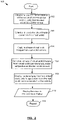
- a flowchart of a method 100 for generating AR images which in this case may be implemented by using an AR platform in a vehicle having at least one camera mounted inside or outside of the vehicle and directed away from the vehicle so that they are oriented to mimic the passengers' view.
- the position and orientation of a given real world camera is defined and calibrated after installation of the given real world camera on the vehicle by measuring the direction that the given real world camera is pointed at. Since the given real world camera is mounted to a known location on the vehicle the position of the given real world camera is always fixed relative to the vehicle. A good assumption can be that the position of the given real world camera can be estimated as the position of the vehicle in the real world.
- the given real world camera orientation may be determined using techniques such as, but not limited to, triangulation or structure from motion (SFM).
- SFM structure from motion
- the field of view of the real world camera is measured as well by techniques such as but not limited to triangulation, direct measurement, or SFM.
- the perspective and viewing direction in the real world can be used to determine the perspective and viewing direction in the virtual world so that the real world and the virtual world become better aligned. This can be repeated for each real world camera that is used.
- the method 100 can start when the AR viewing application 191 is first executed (e.g. launched or started).
- the GPS location of the vehicle and the vehicle's orientation relative to the axes of the real world coordinate projection system are obtained, which is a projection system that is relative to the Earth.
- the projection system may include, but is not limited to, the Universal Transverse Mercator (UTM) coordinate system or the Latitude Longitude coordinate system.
- the vehicle orientation is obtained from embedded modules in the vehicle including but not limited to a magnetometer and a GPS which may be an external GPS (such as standalone GPS devices) or an internal GPS device on board the vehicle and integrated into the vehicle.
- the size of the magnetometer in a vehicle is much larger than the size of a magnetometer in a smart device so the vehicle magnetometer has increased accuracy.
- the orientation of the vehicle may be inferred based on the directionality of the route taken by the vehicle.
- the directionality of the route can be inferred from a world map and the direction of the roads and their orientation.
- the GPS can be used to determine which direction the vehicle is moving along.
- the module to provide the world map may be an internal device or an external device.
- the orientation of the mounted cameras can be determined relative to the vehicle itself and the vehicle's orientation is known relative to the real world projection system, then the orientation of the mounted cameras are inferred relative to the real world projection systems. Consequently, act 102 obtains the location and orientation of the real world cameras.
- the virtual world camera is located and oriented in the virtual world mimicking the movement of the real world camera. This is possible because the location and orientation of the real world camera is known relative to the real world projection system. This may be known at this stage because the orientation of the real world camera is known relative to the vehicle and the vehicle's orientation is known relative to the real world projection system, which makes the orientation and location of the real world camera known relative to the real world projection system.
- a stream of real world images or one or several real world images is captured by at least one mounted real world camera at the vehicle.
- a stream of virtual world images or one or several virtual world images is generated by the renderings of the virtual world from the perspective of the virtual world camera using the virtual content database 196. This may be done through the placement of the virtual world camera in the virtual world so that the virtual world camera has a virtual location, a virtual orientation and a virtual field of view that is as similar as possible to the real location, the real orientation and real field of view of the real world camera. This then allows the virtual world data stream or one or more virtual world images to be captured from the perspective of the virtual world camera in the virtual world.
- the stream of the video images from both the real world and the virtual world are superimposed by overlaying the images from the virtual world on top of the corresponding images of the real world to produce a stream of AR images.
- this may be done for only one virtual world image and one real world image or only a few virtual world images and a few real world images.
- the one or more AR images or a stream of AR images are displayed on a screen held or worn by the passenger.
- the screen may also be a mounted screen in the vehicle.
- the method 100 may repeat acts 102 to 112 to provide one or more additional AR images or AR images streams as long as the AR viewing application 191 is running. For example, for every frame captured by the real world camera, a rendered frame of the virtual world may be generated. In case there is a mismatch between the speed of the frame rate generation of the real world images and the virtual world images, some images associated with the faster frame rate may be discarded.
- FIG. 3 illustrated therein is a flowchart of an example embodiment of a method 120 for generating AR images, which in this case may be implemented by using a hand-held device, such as a smart phone, or a wearable device with a camera and a display, in conjunction with the AR processing unit 185 inside the vehicle.
- the AR processing unit 185 may be provided by an onboard vehicle processor, or a processor of the hand-held device or the wearable device.
- the AR processing unit 185 may be provided by the cloud server as defined in FIG. 1
- the AR processing unit 185 can be centralized or distributed.
- the processing that is done by the AR processing unit 185 may be pushed to other vehicles which have embedded processing units and are in the vicinity of the vehicle which contains the passengers that desire to view at least one AR image.
- the method 120 may be started and stopped in an analogous fashion as method 100.
- the location of the location of the real world camera is obtained from the GPS unit of the AR device being used by the user or the GPS embedded in the vehicle.
- the vehicle's orientation relative to the axes of the real world coordinate projection system is obtained.
- the real world coordinate projection system include, but are not limited to, the Universal Transverse Mercator (UTM) coordinate system or the Latitude Longitude coordinate system.
- the vehicle orientation data may be obtained from embedded modules in the vehicle including, but not limited to, a magnetometer and a GPS.
- the GPS may be external (such as a standalone GPS device).
- the orientation of the vehicle may also be inferred based on the directionality of the route taken by the vehicle as explained previously.
- the camera's orientation and position are determined relative to the marker.
- This marker may be a 2D marker or a 3D marker.
- the tracking can be continued based on the surrounding features using techniques such as SLAM, until the marker again enters the field of view of the real world camera.
- the orientation of the real world camera can be determined using the features of its surroundings such as the interior of the vehicle if the vehicle is not moving too much relative to the AR-device.
- the marker can be used to determine the real world camera's orientation. If a marker is used, the marker has a known orientation and location relative to the vehicle's body. This marker may be placed either on the outside or inside of a vehicle's window and directed to be facing towards the vehicle's interior. Examples of 2D markers include, but are not limited to, images with distinguishable features for computer vision tracking such as edges, non-repetitive patterns, or an image with a high irregularity characteristic. These features may be features that may be trackable by Scale Invariant Feature Transform (SIFT) techniques or SLAM.
- SIFT Scale Invariant Feature Transform
- 3D markers include, but are not limited to, cubes with sides having enough trackable features, and 3D volumes with distinguishable features for SFM tracking to work reliably. These trackable and distinguishable features may be determined using third party software, an example of which is the software produced by Vuforia. Multiple targets may be used and placed at different locations of the interior of the vehicle with a known orientation for keeping tracking consistent at all times. This may be beneficial in situations where a marker that is being tracked by the real world camera to determine the location and orientation of the real world camera is lost and the real world camera can then be oriented relative to other markers, or to the interior of the vehicle or the outside surroundings until the marker is again in the real world camera's field of view and being tracked.
- a 3D model of the vehicle's interior may be constructed and defined as a 3D marker to which the real world camera orients itself.
- the orientation of the real world camera or image capturing device may be known relative to the marker, and by knowing the orientation of the marker relative to the vehicle, the orientation of the real world camera is known relative to the vehicle.
- the orientation of the real world camera may be inferred relative to the real world projection system. Consequently, act 124 provides location data and orientation data for the location and orientation of the real world cameras relative to the real world projection system.
- the location data and the orientation data related to the location and orientation of the AR device's camera is transmitted to a central AR processing unit such as a computer on the cloud (e.g. the cloud server 198).
- This data includes, but is not limited to, GPS data, orientation data of the real world camera relative to the real world projection systems, identity of the marker on the vehicle (i.e. Left facing or Right facing), and the direction of the vehicle movement.
- the cloud server 198 performs the processing that was described previously in method 100 for generating at least one virtual image for viewing by a passenger 192 of the vehicle.
- the view of the virtual world may be rendered at the cloud server 198 from the perspective of the real world camera in the real world since the orientation, location and field of view of the real world camera is known.
- the virtual world is a parallel world to the real world, it is beneficial to have an identical perspective between the two worlds in order to provide more accurate AR images and this has been factored into the method 120.
- the generation of the virtual image data stream may be done by the cloud server 198 and communicated through the network 200 to the AR viewing application 191.
- the rendered stream of virtual images of the view from the virtual world is sent to the user's AR device 184.
- This can be either in the form of a sequence of image data, in the form of a video data stream or in the form of image data for one or several images.
- the video streams from both the real world and the virtual world are superimposed by using techniques such as, but not limited to, comparometric light field or illuminance.
- the real world image stream may be rendered at different depths compared to the virtual world image stream.
- a shader method provided by the graphics engine of the AR processing unit 185 can be used to overlay one or more real world images with one or more virtual world images. Accordingly, the superimposing may be adjusted depending on the transparency of the real world and virtual world image streams which determines the dominance of one stream over the other.
- one or more virtual and real images can be combined rather than a virtual video stream and a real video stream.
- mixed video i.e. AR video
- one or more mixed images i.e. AR images
- the user's AR device 184 has a see through display, only the virtual video stream has to be shown on the display, as the feed of the real world is already being seen through the eyes of the user through the see through display.
- the method 120 may be continually repeated as was explained for act 110 of method 100 for as long as the user is using the AR viewing application 191.
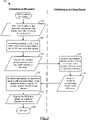
- FIG. 4 illustrated therein is a flowchart of an example embodiment of a method 160 for generating AR images, which in this case may be implemented by using an AR platform of a vehicle which includes a hand-held device with a camera or a wearable device, such as a wearable glass, with a camera and a display. Both the hand-held device and the wearable device have an embedded processing unit for rendering the virtual contents of the virtual world.
- the method 160 is initialized at which point the user may be authenticated, and the GPS unit is turned on. Also the virtual content which corresponds to the surroundings for a position of the user's vehicle can be preloaded for sselling later or can be preloaded for a specific path which is going to be taken by the user. This path may be determined based on input received from the user such as but not limited to the origin and destination of a travel route. Consequently, the virtual world data in the vicinity of the path to be taken by the vehicle may be loaded for visualization.
- the location data about the location of the user or the vehicle will be obtained from the GPS data provided by the GPS unit.
- the user's actual location may be defined at this point but it has a radial error. However, this error can be reduced to a 1D error for the particular situation in which the user is in a vehicle as explained previously.
- the marker can be a 2D marker or a 3D marker.
- 2D markers may include, but are not limited to, images with distinguishable features for computer vision tracking. These features may be features that are trackable by SIFT techniques or the SLAM method as described previously.
- 3D markers include, but are not limited to, cubes with sides having enough trackable features, and 3D volumes with distinguishable features for SFM tracking to work reliably. These features may be features that may be trackable by SIFT techniques or the SLAM method as described previously.
- the tracking may be continued based on the surrounding features using techniques such as SLAM, until the marker again enters the field of view of the real world camera, as was explained previously.
- This marker can be placed either on the vehicle's window and facing inside or it can be located somewhere in the vehicle's interior and faced inwards. Multiple targets may be placed at different locations of the vehicle with known orientation for improving the consistency of tracking.
- a right marker is placed on the right side of the vehicle and a left marker is placed in the left side of the vehicle
- the AR device instead of the AR device locating itself relative to the body of the vehicle when the right marker is lost (causing an accumulation of error), the AR device will see the left marker and localize itself relative to the left marker. Accordingly, this is beneficial in situations where one of the markers is lost during tracking but the display device positions and orients itself with respect to at least one of the other markers. If there are two markers that are in the real world camera's field of view, then the first marker which is found is tracked.
- a 3D model of the vehicle's interior may be constructed and defined as a 3D marker to which the display device orients itself. These 3D models may be acquired through the vehicle's manufacturer or the 3D model may be obtained by using techniques such as SLAM. It may also be possible to construct the 3D model of the vehicle using 3D modelling software.
- location data and orientation data for the location and the orientation of the real world camera is obtained from the GPS unit and the display device orientation data is obtained from the previous acts, respectively.
- the location data and orientation data will be processed and de-noised as much as possible. For example, in the case of GPS data, as the vehicle's position in most of cases is bound to be on a certain route, the de-noising can involve projecting the GPS data onto the route to reduce the location error.
- Another advantage of obtaining the location data from the GPS unit in a moving vehicle is that the GPS data is expected to follow a curve (i.e.
- the travel route which can be estimated based on the previously acquired GPS data points which will significantly help to de-noise and reduce the GPS error from a radial error to a linear error or less than a linear error.
- the GPS data may be projected onto the travel route to be taken which may provide further de-noising and reduce the embedded noise from 2D to 1D.
- the GPS data may be used to infer the orientation of the vehicle by using regression techniques by using methods such as, but not limited to, line fitting the GPS data to determine the direction that is being traveled. For example, as the line over which the vehicle is traveling is being determined, it can be assumed that the upcoming GPS location data points are along the same line.
- the orientation of the vehicle may be determined based on a well-defined travel route which will be taken by the vehicle (i.e. well-defined travel route means that the travel route is pre-determined and known so the vehicle will be traveling along this travel route typically without making any deviations.
- well-defined travel route means that the travel route is pre-determined and known so the vehicle will be traveling along this travel route typically without making any deviations.
- the vehicle's embedded gyroscope may be also used, but usually the GPS data itself is sufficient for estimation of the vehicle's orientation. This data may be obtained by connecting the AR device to the vehicle system and obtaining the data from the appropriate vehicle sensors.
- the vehicle's position as well as its orientation is known relative to the real world coordinate systems such as, but not limited to the UTM or Spherical real world coordinate systems.
- the 2D or 3D marker's position and orientation is known relative to the vehicle's body or housing which determines the position and orientation of the marker relative to the real world.
- the position and orientation of the AR device's camera is known relative to the marker. Also by knowing the orientation of the marker relative to the real world projection system, the position and orientation of the AR device's camera can be inferred relative to the real world projection system, which can therefore be used to determine the viewing direction, orientation and position of the real world camera and consequently determining the viewing direction, orientation and position of the corresponding virtual world camera.
- a parallel virtual world can be constructed as the vehicle is moving in the real world, and a virtual world camera can be moved in the virtual world in a manner that corresponds to the movement and orientation of the real world camera in the real world to allow for the proper combination of virtual world content with real world images.
- the use of a 2D or 3D marker may depend on which type of marker is preferred to be placed in the vehicle. For example, if the vehicle is a touring vehicle, the tour company that owns the vehicle can use specific markers (e.g. 2D images) that are printed and put on a window, or a 3D object (for instance a toy object like a car toy) which is mounted within the vehicle.
- specific markers e.g. 2D images
- a 3D object for instance a toy object like a car toy
- the virtual world data of the real world surroundings of the user may be obtained from the virtual world that is constructed in the previous act.
- the virtual world data may be stored on a data store that may be integral with the AR device, or may be an onboard vehicle database or may be stored on a remote database from which it is downloaded to the AR device during use.
- the data store may store content that has been either uploaded by the user using processing device 194 in some cases, or has been arranged and created by the creator or a system administrator using the cloud server 198.
- the cloud server 198 may generate the virtual content autonomously, using a software code, which may consider factors such as context, geography, and cultural norms in content placement.
- This may be done by correlating tags related to the context with tags associated with the virtual content in order to determine whether or not to place a virtual object at a specific location in the virtual world.
- some degree of randomness may be added to provide some unpredictability in the created virtual world thereby varying the AR experience when the same user uses the AR device in the same real world location.
- the AR processing unit on the AR device may be used to mix, overlay or otherwise combine, as described previously, the virtual world image data or the virtual world image stream of the virtual world camera from the virtual world with the corresponding real world image data or real world image stream of the real world obtained from the real world camera.
- the combined images or video stream can be displayed on the user's display.
- the user's device has a see through display, only the virtual video stream or virtual image data may be displayed on the screen, as the real world is already being seen through the eyes of the user as they view the see through display.
- the method may be repeated to produce a continuous stream of images.
- the method 160 may be repeatedly performed as long as the AR viewing application is running.
- GPS data interpolation may be done.
- Techniques such as velocity and acceleration estimations might be used along with one of linear regression fitting, Bezier curve fitting, and higher degree regression curve fitting for interpolation of GPS data.
- markers can be made invisible to the naked eye and to RGB cameras. Therefore, instead of performing marker detection via an RGB camera, an infrared camera (which includes a depth sensor that works based on time of flight measurement) camera can be used for detection the location of the 2D or 3D marker in order to determine the orientation of the AR device relative to the marker.
- an infrared camera which includes a depth sensor that works based on time of flight measurement
- This can be performed by using a transparent sheet which has different absorption characteristics to the emitted light from a depth sensor throughout the marker. So in a sense, the same marker which is not being detected by the RGB camera will be detected via a depth sensor camera that emits infrared light.
- Marker features are engraved on the transparent sheet to vary the light absorption in different locations of the sheet. This light absorption characteristic can be integrated into the windows of the vehicle itself by making these windows from materials which have different light absorption at different light frequencies. Moreover, the absorption characteristic can be tailored for the specific frequency of the light which is used in the time of flight
Landscapes
- Engineering & Computer Science (AREA)
- Physics & Mathematics (AREA)
- General Physics & Mathematics (AREA)
- Theoretical Computer Science (AREA)
- General Engineering & Computer Science (AREA)
- Mechanical Engineering (AREA)
- Optics & Photonics (AREA)
- Human Computer Interaction (AREA)
- Chemical & Material Sciences (AREA)
- Combustion & Propulsion (AREA)
- Transportation (AREA)
- Software Systems (AREA)
- Computer Hardware Design (AREA)
- Computer Graphics (AREA)
- Processing Or Creating Images (AREA)
- Multimedia (AREA)
- User Interface Of Digital Computer (AREA)
Claims (16)
- System der erweiterten Realität (ER), das es einem Nutzer in einem Fahrzeug ermöglicht, zumindest ein Bild der erweiterten Realität von einem Teil der Fahrzeugumgebung zu sehen, wobei das Fahrzeugsystem mit erweiterter Realität Folgendes umfasst:wenigstens eine Kamera der realen Welt für den Erhalt von Bilddaten aus der realen Welt von einem Teil der Fahrzeugumgebung;wenigstens eine Anzeige, um es dem Benutzer zu ermöglichen, zumindest ein Bild der erweiterten Realität zu betrachten;eine Ortungseinheit, die dafür konfiguriert ist, Ortungsdaten für einen Ort der wenigstens einen Kamera der realen Welt im Verhältnis zu einem Koordinatensystem der realen Welt zu bestimmen;eine Ausrichtungseinheit, die dafür konfiguriert ist, Ortungsdaten für einen Ort der wenigstens einen Kamera der realen Welt im Verhältnis zu einem Koordinatensystem der realen Welt zu bestimmen;eine virtuelle Inhaltsdatenbank, die Daten virtueller Welten umfasst; undeine Verarbeitungseinheit der erweiterten Realität mit einer Konfiguration für Folgendes:Erhalten eines Ansichtsfelds der wenigstens einen Kamera der realen Welt;Erzeugung einer Kamera der virtuellen Welt an einem virtuellen Ort, mit einer virtuellen Ausrichtung und einem virtuellen Ansichtsfeld, das mit dem Ort, der Ausrichtung und dem Ansichtsfeld der realen Kamera identisch ist;Erhalten von wenigstens einem Bild der virtuellen Welt von einem Teil der Daten der virtuellen Welt, die dem virtuellen Ort, der virtuellen Ausrichtung und dem virtuellen Ansichtsfeld der Kamera der virtuellen Welt entspricht;Erzeugung von wenigstens einem Bild der erweiterten Realität durch Kombinieren der wenigstens einen Bilddatei der virtuellen Welt mit der wenigstens einen Bilddatei der realen Welt; undAnzeigen des wenigstens einen Bildes der erweiterten Realität auf der wenigstens einen Anzeige;dadurch gekennzeichnet, dasswenigstens eine Bildmarkierung, die sich im Fahrzeug befindet und verwendet wird, wenn die wenigstens eine Kamera der realen Welt über ein Handgerät oder eine tragbare Vorrichtung bereitgestellt wird, wobei die wenigstens eine Bildmarkierung dazu dient, bei der Ausrichtung der wenigstens einen Kamera der realen Welt im Verhältnis zum Fahrzeug zu helfen,wobei die Ausrichtung der wenigstens einen Kamera der realen Welt im Verhältnis zu der wenigstens einen Bildmarkierung bekannt ist und die wenigstens eine Markierung eine bekannte Ausrichtung und Position im Verhältnis zur Fahrzeugkarosserie hat, die von der Ausrichtungseinheit verwendet wird, um bei der Ausrichtung zu helfen, und folglich zum Bestimmen der Ausrichtung der wenigstens einen Kamera der realen Welt relativ zur Fahrzeugkarosserie und dadurch der Ausrichtung der wenigstens einen Kamera der realen Welt im Verhältnis zum Koordinatensystem der realen Welt basierend auf einer bekannten Ausrichtung der Fahrzeugkarosserie zum Koordinatensystem der realen Welt.
- System der erweiterten Realität nach Anspruch 1, wobei die Kombination der erhaltenen Bilddaten der virtuellen Welt in Bezug auf das wenigstens eine Bild der realen Welt im digitalen Bereich erfolgt, bevor das wenigstens eine Bild der erweiterten Realität auf der Anzeige angezeigt wird.
- System der erweiterten Realität nach Anspruch 1, wobei die Kombination der erhaltenen Daten der virtuellen Welt in Bezug auf das wenigstens eine Bild der realen Welt auf der Anzeige angezeigt wird, da es von dem Nutzer angesehen wird.
- System der erweiterten Realität nach Anspruch 1, wobei die Ortungseinheit eine Einheit eines globalen Positionierungssystems (GPS) des Fahrzeugs zum Bestimmen der Ortungsdaten umfasst.
- System der erweiterten Realität nach Anspruch 4, wobei die Verarbeitungseinheit der erweiterten Realität zum Korrigieren von GPS-Fehlern in den Ortungsdaten konfiguriert ist.
- System der erweiterten Realität nach Anspruch 1, wobei die Verarbeitungseinheit der erweiterten Realität von einem Server bereitgestellt wird, der durch ein drahtloses Netzwerk mit dem Fahrzeug gekoppelt ist.
- System der erweiterten Realität nach Anspruch 1, wobei die Verarbeitungseinheit der erweiterten Realität durch eine Verarbeitungseinheit eines Fahrzeugs, eine Verarbeitungseinheit eines Handgeräts und eine Verarbeitungseinheit eines tragbaren Geräts bereitgestellt wird.
- System der erweiterten Realität nach Anspruch 1, wobei die wenigstens eine Bildmarkierung am Fahrzeug an einer Stelle montiert und auf einen Innenteil des Fahrzeugs gerichtet ist, so dass sich die wenigstens eine Bildmarkierung im Ansichtsfeld der wenigstens einen Kamera der realen Welt befindet, wenn die wenigstens eine Kamera der realen Welt durch das Handgerät oder das tragbare Gerät bereitgestellt wird und auf die Fahrzeugumgebung gerichtet ist.
- System der erweiterten Realität nach Anspruch 1, wobei die wenigstens eine Markierung eine oder mehrere der wenigstens einen 2D-Bildmarkierung und wenigstens einen 3D-Bildmarkierung umfasst.
- System der erweiterten Realität nach Anspruch 1, wobei die virtuelle Inhaltsdatenbank wenigstens ein virtuelles 3D-Modell, wenigstens ein virtuelles 2D-Bild, wenigstens ein virtuelles 3D-Bild der Anordnung der virtuellen Objekte in der virtuellen Welt und virtuelle Textdaten enthält, die Informationen über die virtuellen Objekte geben.
- System der erweiterten Realität nach Anspruch 1, wobei die wenigstens eine Kamera der realen Welt durch ein Handgerät oder ein tragbares Gerät bereitgestellt wird, das im Verhältnis zu wenigstens einer an dem Fahrzeug angebrachten Bildmarkierung basierend auf der Ausrichtung der wenigstens einen Bildmarkierung im Verhältnis zu dem Fahrzeug und der Ausrichtung des Fahrzeugs zu einem Projektionssystem der realen Welt ausgerichtet ist.
- System der erweiterten Realität nach Anspruch 1, wobei die wenigstens eine Kamera der realen Welt, die an dem wenigstens einen Fahrzeug angebracht ist, während einer Installations- und Kalibrierungsphase im Verhältnis zu dem wenigstens einen Fahrzeug ausgerichtet wird und folglich im Verhältnis zu einem Projektionssystem der realen Welt ausgerichtet wird basierend auf der Ausrichtung des wenigstens einen Fahrzeugs im Verhältnis zum Projektionssystem der realen Welt.
- System der erweiterten Realität nach Anspruch 1, wobei die wenigstens eine Kamera der realen Welt durch eine oder mehreren von wenigstens einer Bordkamera eines Fahrzeugs, wenigstens einer an einem Fenster des Fahrzeugs angebrachten Kamera, wenigstens einem Handgerät und wenigstens einem tragbaren Gerät bereitgestellt wird.
- System der erweiterten Realität nach Anspruch 1, wobei die wenigstens eine Anzeige durch eine der wenigstens einen oder mehreren Bordanzeigen eines Fahrzeugs, wenigstens einer Anzeige, wenigstens einem Handgerät und wenigstens einem tragbaren Gerät bereitgestellt wird.
- Verfahren zum Erzeugen wenigstens eines Bildes der erweiterten Realität (ER) von einem Teil der Fahrzeugumgebung zum Betrachten durch einen Nutzer in dem Fahrzeug, wobei das Verfahren Folgendes umfasst:Erhalten von wenigstens einer Bilddatei der erweiterten Realität von einem Teil der Fahrzeugumgebung unter Verwendung von wenigstens einer Kamera der realen Welt, die dem Fahrzeug oder dem Nutzer zugeordnet ist;Bestimmung von Ortungsdaten für einen Ort der wenigstens einen Kamera der realen Welt im Verhältnis zu einem Koordinatensystem der realen Welt unter Verwendung einer Ortungseinheit;Bestimmung von Ausrichtungsdaten zur Ausrichtung der wenigstens einen Kamera der realen Welt im Verhältnis zum Koordinatensystem der realen Welt unter Verwendung einer Ausrichtungseinheit;bei einer Verarbeitungseinheit der erweiterten Realität:Erhalten eines Ansichtsfelds der wenigstens einen Kamera der realen Welt;Erzeugung von wenigstens einer Kamera der virtuellen Welt mit einem virtuellen Ort, einer virtuellen Ausrichtung und einem virtuellen Ansichtsfeld, das mit dem Ort, der Ausrichtung und dem Ansichtsfeld der realen Kamera identisch ist;Erhalten von wenigstens einer Bilddatei der virtuellen Welt von einem Teil der Daten der virtuellen Welt, die dem virtuellen Ort, der virtuellen Ausrichtung und dem virtuellen Ansichtsfeld der wenigstens einer Kamera der virtuellen Welt entspricht; undErzeugung von wenigstens einer Bilddatei der erweiterten Realität durch Kombinieren der wenigstens einer Bilddatei der virtuellen Welt mit der wenigstens einen Bilddatei der realen Welt; undAnzeigen des wenigstens einen Bildes der erweiterten Realität auf der wenigstens einen Anzeige zum Betrachten für den Nutzer;dadurch gekennzeichnet, dassdie Bestimmung der Ausrichtung die Verwendung der wenigstens einen Bildmarkierung in dem Fahrzeug umfasst, um bei der Ausrichtung der wenigstens einen Kamera der realen Welt im Verhältnis zum Fahrzeug zu helfen, wobei die Ausrichtung der wenigstens einen Kamera der realen Welt im Verhältnis zu der wenigstens einen Bildmarkierung bekannt ist und die wenigstens eine genannte Bildmarkierung eine bekannte Ausrichtung und Position im Verhältnis zur Fahrzeugkarosserie hat, um bei der genannten Ausrichtung zu helfen, und folglich zur Bestimmung der Ausrichtung der wenigstens einen Kamera der realen Welt im Verhältnis zur Fahrzeugkarosserie und dadurch der Ausrichtung der wenigstens einen Kamera der realen Welt im Verhältnis zum Koordinatensystem der realen Welt basierend auf einer genannten Ausrichtung der Fahrzeugkarosserie zum Koordinatensystem der realen Welt.
- Ein nichtflüchtiges computerlesbares Medium, das computerausführbare Anweisungen speichert, wobei die Anweisungen bei Ausführung mindestens eine Verarbeitungseinheit dazu veranlassen, ein Verfahren zum Generieren mindestens eines ER-Bilds (erweiterte Realität) eines Teils der Fahrzeugumgebung zum Betrachten durch einen Benutzer auszuführen in dem Fahrzeug, wobei das Verfahren Folgendes umfasst:Erhalten von wenigstens einer Bilddatei der erweiterten Realität von einem Teil der Fahrzeugumgebung von wenigstens einer Kamera der realen Welt, die dem Fahrzeug oder dem Nutzer zugeordnet ist;Bestimmung von Ausrichtungsdaten zur Ausrichtung der wenigstens einen Kamera der realen Welt im Verhältnis zum Koordinatensystem der realen Welt unter Verwendung einer Ortungseinheit; Bestimmung von Ausrichtungsdaten zur Ausrichtung der wenigstens einen Kamera der realen Welt im Verhältnis zum Koordinatensystem der realen Welt unter Verwendung einer Ausrichtungseinheit; Erhalten eines Ansichtsfelds der wenigstens einen Kamera der realen Welt;Erzeugung von wenigstens einer Kamera der virtuellen Welt mit einem virtuellen Ort, einer virtuellen Ausrichtung und einem virtuellen Ansichtsfeld, das mit dem Ort, der Ausrichtung und dem Ansichtsfeld der realen Kamera identisch ist;Erhalten von wenigstens einer Bilddatei der virtuellen Welt von einem Teil der Daten der virtuellen Welt, die dem virtuellen Ort, der virtuellen Ausrichtung und dem virtuellen Ansichtsfeld der Kamera der virtuellen Welt entspricht;Erzeugung von wenigstens einem Bild der erweiterten Realität durch Kombinieren der wenigstens einen virtuellen Bilddatei mit der wenigstens einen Bilddatei der realen Welt; undAnzeigen des wenigstens einen Bildes der erweiterten Realität auf einer Anzeige zum Betrachten für den Nutzer,dadurch gekennzeichnet, dassdie Bestimmung der Ausrichtung die Verwendung der wenigstens einen Bildmarkierung in dem Fahrzeug umfasst, um bei der Ausrichtung der wenigstens einen Kamera der realen Welt im Verhältnis zum Fahrzeug zu helfen, wobei die Ausrichtung der wenigstens einen Kamera der realen Welt im Verhältnis zu der wenigstens einen Bildmarkierung bekannt ist und die wenigstens eine genannte Markierung eine bekannte Ausrichtung und Position im Verhältnis zur Fahrzeugkarosserie hat, die von der Ausrichtungseinheit verwendet wird, um bei der genannten Ausrichtung zu helfen, und folglich zur Bestimmung der Ausrichtung der wenigstens einen Kamera der realen Welt im Verhältnis zur Fahrzeugkarosserie und dadurch der Ausrichtung der wenigstens einen Kamera der realen Welt im Verhältnis zum Koordinatensystem der realen Welt basierend auf einer genannten Ausrichtung der Fahrzeugkarosserie zum Koordinatensystem der realen Welt.
Applications Claiming Priority (2)
| Application Number | Priority Date | Filing Date | Title |
|---|---|---|---|
| US201562200985P | 2015-08-04 | 2015-08-04 | |
| PCT/CA2016/050913 WO2017020132A1 (en) | 2015-08-04 | 2016-08-04 | Augmented reality in vehicle platforms |
Publications (3)
| Publication Number | Publication Date |
|---|---|
| EP3338136A1 EP3338136A1 (de) | 2018-06-27 |
| EP3338136A4 EP3338136A4 (de) | 2019-03-27 |
| EP3338136B1 true EP3338136B1 (de) | 2022-09-14 |
Family
ID=57942192
Family Applications (1)
| Application Number | Title | Priority Date | Filing Date |
|---|---|---|---|
| EP16832019.0A Active EP3338136B1 (de) | 2015-08-04 | 2016-08-04 | Erweiterte realität in fahrzeugplattformen |
Country Status (3)
| Country | Link |
|---|---|
| US (1) | US10977865B2 (de) |
| EP (1) | EP3338136B1 (de) |
| WO (1) | WO2017020132A1 (de) |
Cited By (1)
| Publication number | Priority date | Publication date | Assignee | Title |
|---|---|---|---|---|
| DE102022134635A1 (de) | 2022-12-22 | 2024-06-27 | Rheinmetall Air Defence Ag | System und Verfahren zur Positionsbestimmung von Objekten in einem Überwachungsgebiet |
Families Citing this family (39)
| Publication number | Priority date | Publication date | Assignee | Title |
|---|---|---|---|---|
| US9836895B1 (en) | 2015-06-19 | 2017-12-05 | Waymo Llc | Simulating virtual objects |
| US10424117B2 (en) * | 2015-12-02 | 2019-09-24 | Seiko Epson Corporation | Controlling a display of a head-mounted display device |
| WO2017192467A1 (en) * | 2016-05-02 | 2017-11-09 | Warner Bros. Entertainment Inc. | Geometry matching in virtual reality and augmented reality |
| US10467980B2 (en) * | 2017-03-07 | 2019-11-05 | Panasonic Avionics Corporation | Systems and methods for supporting augmented reality applications on a transport vehicle |
| NO342793B1 (en) | 2017-06-20 | 2018-08-06 | Augmenti As | Augmented reality system and method of displaying an augmented reality image |
| US10559133B2 (en) * | 2018-02-07 | 2020-02-11 | Dell Products L.P. | Visual space management across information handling system and augmented reality |
| US11107281B2 (en) * | 2018-05-18 | 2021-08-31 | Valeo Comfort And Driving Assistance | Shared environment for vehicle occupant and remote user |
| GB2579080A (en) * | 2018-11-19 | 2020-06-10 | Cosworth Group Holdings Ltd | Improvements in or relating to perception modules |
| EP3663942B1 (de) * | 2018-12-07 | 2023-04-26 | Volvo Car Corporation | Beurteilung eines features einer simulierten fahrzeugfunktionalität |
| US11302217B2 (en) * | 2019-01-17 | 2022-04-12 | Toyota Motor North America, Inc. | Augmented reality dealer vehicle training manual |
| WO2020165885A1 (en) * | 2019-02-13 | 2020-08-20 | Quaqua Experiences Pvt. Ltd. | Computer-implemented method and system for providing interaction rules in mixed reality |
| US10767997B1 (en) * | 2019-02-25 | 2020-09-08 | Qualcomm Incorporated | Systems and methods for providing immersive extended reality experiences on moving platforms |
| US12198695B2 (en) * | 2019-05-31 | 2025-01-14 | Apple Inc. | Voice assistant discoverability through on-device targeting and personalization |
| US12040993B2 (en) | 2019-06-18 | 2024-07-16 | The Calany Holding S. À R.L. | Software engine virtualization and dynamic resource and task distribution across edge and cloud |
| US12033271B2 (en) | 2019-06-18 | 2024-07-09 | The Calany Holding S. À R.L. | 3D structure engine-based computation platform |
| US12039354B2 (en) | 2019-06-18 | 2024-07-16 | The Calany Holding S. À R.L. | System and method to operate 3D applications through positional virtualization technology |
| DE102019213740A1 (de) * | 2019-09-10 | 2021-03-11 | Audi Ag | Verfahren zum Betreiben eines am Kopf tragbaren Anzeigegeräts in einem Kraftfahrzeug, Steuereinrichtung, und am Kopf tragbares Anzeigegerät |
| US11127373B2 (en) * | 2019-10-30 | 2021-09-21 | Ford Global Technologies, Llc | Augmented reality wearable system for vehicle occupants |
| US11182970B1 (en) | 2019-12-09 | 2021-11-23 | Rockwell Collins, Inc. | Augmented reality aircraft window and method |
| US11210519B2 (en) * | 2020-01-15 | 2021-12-28 | Trimble Inc. | Providing augmented reality images to an operator of a machine |
| JP7162795B2 (ja) * | 2020-06-09 | 2022-10-31 | プレティア・テクノロジーズ株式会社 | 映像処理システム |
| US11734895B2 (en) | 2020-12-14 | 2023-08-22 | Toyota Motor North America, Inc. | Systems and methods for enabling precise object interaction within an augmented reality environment |
| CN112905005B (zh) * | 2021-01-22 | 2024-12-10 | 领悦数字信息技术有限公司 | 用于车辆的自适应显示方法、装置及存储介质 |
| US11593996B2 (en) | 2021-02-09 | 2023-02-28 | Waymo Llc | Synthesizing three-dimensional visualizations from perspectives of onboard sensors of autonomous vehicles |
| KR20220149203A (ko) | 2021-04-30 | 2022-11-08 | 현대자동차주식회사 | 모빌리티 장치 및 그 제어방법 |
| CN113377205B (zh) * | 2021-07-06 | 2022-11-11 | 浙江商汤科技开发有限公司 | 场景显示方法及装置、设备、车辆、计算机可读存储介质 |
| CN113608614A (zh) * | 2021-08-05 | 2021-11-05 | 上海商汤智能科技有限公司 | 展示方法、增强现实装置、设备及计算机可读存储介质 |
| CN113641248A (zh) * | 2021-09-10 | 2021-11-12 | 天津天汽集团有限公司 | 一种车内增强现实娱乐的实现系统及方法 |
| US11691566B2 (en) * | 2021-11-17 | 2023-07-04 | GM Global Technology Operations LLC | Intelligent vehicle systems and control logic for surround view augmentation with object model recognition |
| KR20230074360A (ko) * | 2021-11-19 | 2023-05-30 | 현대자동차주식회사 | 차량 및 그 제어 방법 |
| CN114415828B (zh) * | 2021-12-27 | 2025-02-14 | 北京五八信息技术有限公司 | 一种基于增强现实的远程查看车辆的方法和装置 |
| US12005919B2 (en) | 2022-02-22 | 2024-06-11 | Toyota Research Institute, Inc. | Varying extended reality content based on risk level of a driving environment |
| US12195006B2 (en) | 2022-02-22 | 2025-01-14 | Toyota Research Institute, Inc. | Varying extended reality content based on driver attentiveness |
| CN117289784B (zh) * | 2022-06-17 | 2025-04-29 | 北京邮电大学 | 元宇宙环境下用户获得模型的方法、装置以及电子设备 |
| EP4309942A1 (de) * | 2022-07-18 | 2024-01-24 | Volvo Truck Corporation | Mit einem mensch-maschine-schnittstellenstatus angereichertes visuelles fahrerhandbuch in der erweiterten realität |
| JP2024041343A (ja) * | 2022-09-14 | 2024-03-27 | 本田技研工業株式会社 | 情報処理装置、情報処理システム、および情報処理方法 |
| CN115690194B (zh) * | 2022-10-17 | 2023-09-19 | 广州赤兔宸行科技有限公司 | 一种车载xr设备定位方法、装置、设备及存储介质 |
| US12287860B2 (en) * | 2023-01-12 | 2025-04-29 | Ford Global Technologies, Llc | Systems and methods for permitting access to a human machine interface in a vehicle |
| US20250124619A1 (en) * | 2023-10-12 | 2025-04-17 | Textron Inc. | Augmented reality safety glasses |
Citations (2)
| Publication number | Priority date | Publication date | Assignee | Title |
|---|---|---|---|---|
| US20120236119A1 (en) * | 2011-01-20 | 2012-09-20 | Samsung Electronics Co., Ltd. | Apparatus and method for estimating camera motion using depth information, and augmented reality system |
| US20130004920A1 (en) * | 2010-03-24 | 2013-01-03 | Krauss-Maffei Wegmann Gmbh & Co. Kg | Method for Training a Crew Member of a, in Particular, Military Vehicle |
Family Cites Families (12)
| Publication number | Priority date | Publication date | Assignee | Title |
|---|---|---|---|---|
| EP1889007B1 (de) * | 2005-06-06 | 2009-08-26 | TomTom International B.V. | Navigationseinrichtung mit kamera-info |
| US20110153198A1 (en) | 2009-12-21 | 2011-06-23 | Navisus LLC | Method for the display of navigation instructions using an augmented-reality concept |
| US9237844B2 (en) * | 2010-03-22 | 2016-01-19 | Koninklijke Philips N.V. | System and method for tracking the point of gaze of an observer |
| US20120038668A1 (en) | 2010-08-16 | 2012-02-16 | Lg Electronics Inc. | Method for display information and mobile terminal using the same |
| US20120050144A1 (en) * | 2010-08-26 | 2012-03-01 | Clayton Richard Morlock | Wearable augmented reality computing apparatus |
| EP2608153A1 (de) * | 2011-12-21 | 2013-06-26 | Harman Becker Automotive Systems GmbH | Verfahren und System zum Spielen eines Spiels mit erweiterter Realität in einem Motorfahrzeug |
| JP5921320B2 (ja) | 2012-04-27 | 2016-05-24 | 富士通テン株式会社 | 表示システム、携帯装置、車載装置、及び、プログラム |
| US9420275B2 (en) * | 2012-11-01 | 2016-08-16 | Hexagon Technology Center Gmbh | Visual positioning system that utilizes images of a working environment to determine position |
| US9208390B2 (en) | 2012-11-12 | 2015-12-08 | Wilfred Ludick | Intra-vehicular mobile device management |
| US20140168264A1 (en) | 2012-12-19 | 2014-06-19 | Lockheed Martin Corporation | System, method and computer program product for real-time alignment of an augmented reality device |
| US20140278053A1 (en) * | 2013-03-14 | 2014-09-18 | Samsung Electronics Co., Ltd. | Navigation system with dynamic update mechanism and method of operation thereof |
| US9550419B2 (en) | 2014-01-21 | 2017-01-24 | Honda Motor Co., Ltd. | System and method for providing an augmented reality vehicle interface |
-
2016
- 2016-08-04 EP EP16832019.0A patent/EP3338136B1/de active Active
- 2016-08-04 US US15/749,552 patent/US10977865B2/en active Active
- 2016-08-04 WO PCT/CA2016/050913 patent/WO2017020132A1/en not_active Ceased
Patent Citations (2)
| Publication number | Priority date | Publication date | Assignee | Title |
|---|---|---|---|---|
| US20130004920A1 (en) * | 2010-03-24 | 2013-01-03 | Krauss-Maffei Wegmann Gmbh & Co. Kg | Method for Training a Crew Member of a, in Particular, Military Vehicle |
| US20120236119A1 (en) * | 2011-01-20 | 2012-09-20 | Samsung Electronics Co., Ltd. | Apparatus and method for estimating camera motion using depth information, and augmented reality system |
Cited By (1)
| Publication number | Priority date | Publication date | Assignee | Title |
|---|---|---|---|---|
| DE102022134635A1 (de) | 2022-12-22 | 2024-06-27 | Rheinmetall Air Defence Ag | System und Verfahren zur Positionsbestimmung von Objekten in einem Überwachungsgebiet |
Also Published As
| Publication number | Publication date |
|---|---|
| US20180225875A1 (en) | 2018-08-09 |
| EP3338136A4 (de) | 2019-03-27 |
| US10977865B2 (en) | 2021-04-13 |
| WO2017020132A1 (en) | 2017-02-09 |
| EP3338136A1 (de) | 2018-06-27 |
Similar Documents
| Publication | Publication Date | Title |
|---|---|---|
| EP3338136B1 (de) | Erweiterte realität in fahrzeugplattformen | |
| US11644832B2 (en) | User interaction paradigms for a flying digital assistant | |
| US11127373B2 (en) | Augmented reality wearable system for vehicle occupants | |
| US9495783B1 (en) | Augmented reality vision system for tracking and geolocating objects of interest | |
| CN106462232B (zh) | 用于在动态环境中确定坐标框架的方法和系统 | |
| EP2950530B1 (de) | Anzeigevorrichtung für meeresumgebung | |
| US10532814B2 (en) | Augmented reality travel route planning | |
| CN102446048B (zh) | 信息处理设备以及信息处理方法 | |
| CN112102497A (zh) | 用于将应用和交互附接到静态对象的系统和方法 | |
| CN112074875A (zh) | 构造3d特征图的组优化深度信息方法和系统 | |
| US11967035B1 (en) | Visualizing area covered by drone camera | |
| US9534902B2 (en) | Time phased imagery for an artificial point of view | |
| US11841741B2 (en) | Composite pose estimate for wearable computing device | |
| EP3114650A2 (de) | Systeme und verfahren zur virtuellen anzeige physikalischer ereignisse | |
| US11516296B2 (en) | Location-based application stream activation | |
| JP6345381B2 (ja) | 拡張現実システム | |
| WO2024031141A1 (en) | Systems and methods for generating and/or using 3-dimensional information with one or more moving cameras | |
| US20200217665A1 (en) | Mobile platform, image capture path generation method, program, and recording medium | |
| CN102200444B (zh) | 实时扩增实境装置及其实时扩增实境方法 | |
| JP2009276266A (ja) | ナビゲーション装置 | |
| KR20220117738A (ko) | 스마트폰 위치기반 게임장치 및 방법 | |
| CN113450439A (zh) | 一种虚实融合方法、设备及系统 |
Legal Events
| Date | Code | Title | Description |
|---|---|---|---|
| STAA | Information on the status of an ep patent application or granted ep patent |
Free format text: STATUS: THE INTERNATIONAL PUBLICATION HAS BEEN MADE |
|
| PUAI | Public reference made under article 153(3) epc to a published international application that has entered the european phase |
Free format text: ORIGINAL CODE: 0009012 |
|
| STAA | Information on the status of an ep patent application or granted ep patent |
Free format text: STATUS: REQUEST FOR EXAMINATION WAS MADE |
|
| 17P | Request for examination filed |
Effective date: 20180226 |
|
| AK | Designated contracting states |
Kind code of ref document: A1 Designated state(s): AL AT BE BG CH CY CZ DE DK EE ES FI FR GB GR HR HU IE IS IT LI LT LU LV MC MK MT NL NO PL PT RO RS SE SI SK SM TR |
|
| AX | Request for extension of the european patent |
Extension state: BA ME |
|
| DAV | Request for validation of the european patent (deleted) | ||
| DAX | Request for extension of the european patent (deleted) | ||
| A4 | Supplementary search report drawn up and despatched |
Effective date: 20190227 |
|
| RIC1 | Information provided on ipc code assigned before grant |
Ipc: G02B 27/01 20060101AFI20190221BHEP Ipc: B60K 35/00 20060101ALI20190221BHEP Ipc: G06T 11/60 20060101ALI20190221BHEP Ipc: B60R 11/04 20060101ALI20190221BHEP |
|
| STAA | Information on the status of an ep patent application or granted ep patent |
Free format text: STATUS: EXAMINATION IS IN PROGRESS |
|
| 17Q | First examination report despatched |
Effective date: 20201002 |
|
| REG | Reference to a national code |
Ref country code: DE Ref legal event code: R079 Ref document number: 602016075048 Country of ref document: DE Free format text: PREVIOUS MAIN CLASS: G02B0027010000 Ipc: G06F0003010000 |
|
| RIC1 | Information provided on ipc code assigned before grant |
Ipc: G06T 11/60 20060101ALI20220302BHEP Ipc: B60R 11/04 20060101ALI20220302BHEP Ipc: B60K 35/00 20060101ALI20220302BHEP Ipc: G02B 27/01 20060101ALI20220302BHEP Ipc: G06F 3/01 20060101AFI20220302BHEP |
|
| GRAP | Despatch of communication of intention to grant a patent |
Free format text: ORIGINAL CODE: EPIDOSNIGR1 |
|
| STAA | Information on the status of an ep patent application or granted ep patent |
Free format text: STATUS: GRANT OF PATENT IS INTENDED |
|
| INTG | Intention to grant announced |
Effective date: 20220411 |
|
| GRAS | Grant fee paid |
Free format text: ORIGINAL CODE: EPIDOSNIGR3 |
|
| GRAA | (expected) grant |
Free format text: ORIGINAL CODE: 0009210 |
|
| STAA | Information on the status of an ep patent application or granted ep patent |
Free format text: STATUS: THE PATENT HAS BEEN GRANTED |
|
| AK | Designated contracting states |
Kind code of ref document: B1 Designated state(s): AL AT BE BG CH CY CZ DE DK EE ES FI FR GB GR HR HU IE IS IT LI LT LU LV MC MK MT NL NO PL PT RO RS SE SI SK SM TR |
|
| REG | Reference to a national code |
Ref country code: GB Ref legal event code: FG4D |
|
| REG | Reference to a national code |
Ref country code: CH Ref legal event code: EP |
|
| REG | Reference to a national code |
Ref country code: DE Ref legal event code: R096 Ref document number: 602016075048 Country of ref document: DE |
|
| REG | Reference to a national code |
Ref country code: IE Ref legal event code: FG4D |
|
| REG | Reference to a national code |
Ref country code: AT Ref legal event code: REF Ref document number: 1519110 Country of ref document: AT Kind code of ref document: T Effective date: 20221015 |
|
| REG | Reference to a national code |
Ref country code: LT Ref legal event code: MG9D |
|
| REG | Reference to a national code |
Ref country code: NL Ref legal event code: MP Effective date: 20220914 |
|
| PG25 | Lapsed in a contracting state [announced via postgrant information from national office to epo] |
Ref country code: SE Free format text: LAPSE BECAUSE OF FAILURE TO SUBMIT A TRANSLATION OF THE DESCRIPTION OR TO PAY THE FEE WITHIN THE PRESCRIBED TIME-LIMIT Effective date: 20220914 Ref country code: RS Free format text: LAPSE BECAUSE OF FAILURE TO SUBMIT A TRANSLATION OF THE DESCRIPTION OR TO PAY THE FEE WITHIN THE PRESCRIBED TIME-LIMIT Effective date: 20220914 Ref country code: NO Free format text: LAPSE BECAUSE OF FAILURE TO SUBMIT A TRANSLATION OF THE DESCRIPTION OR TO PAY THE FEE WITHIN THE PRESCRIBED TIME-LIMIT Effective date: 20221214 Ref country code: LV Free format text: LAPSE BECAUSE OF FAILURE TO SUBMIT A TRANSLATION OF THE DESCRIPTION OR TO PAY THE FEE WITHIN THE PRESCRIBED TIME-LIMIT Effective date: 20220914 Ref country code: LT Free format text: LAPSE BECAUSE OF FAILURE TO SUBMIT A TRANSLATION OF THE DESCRIPTION OR TO PAY THE FEE WITHIN THE PRESCRIBED TIME-LIMIT Effective date: 20220914 Ref country code: FI Free format text: LAPSE BECAUSE OF FAILURE TO SUBMIT A TRANSLATION OF THE DESCRIPTION OR TO PAY THE FEE WITHIN THE PRESCRIBED TIME-LIMIT Effective date: 20220914 |
|
| REG | Reference to a national code |
Ref country code: AT Ref legal event code: MK05 Ref document number: 1519110 Country of ref document: AT Kind code of ref document: T Effective date: 20220914 |
|
| PG25 | Lapsed in a contracting state [announced via postgrant information from national office to epo] |
Ref country code: HR Free format text: LAPSE BECAUSE OF FAILURE TO SUBMIT A TRANSLATION OF THE DESCRIPTION OR TO PAY THE FEE WITHIN THE PRESCRIBED TIME-LIMIT Effective date: 20220914 Ref country code: GR Free format text: LAPSE BECAUSE OF FAILURE TO SUBMIT A TRANSLATION OF THE DESCRIPTION OR TO PAY THE FEE WITHIN THE PRESCRIBED TIME-LIMIT Effective date: 20221215 |
|
| PG25 | Lapsed in a contracting state [announced via postgrant information from national office to epo] |
Ref country code: SM Free format text: LAPSE BECAUSE OF FAILURE TO SUBMIT A TRANSLATION OF THE DESCRIPTION OR TO PAY THE FEE WITHIN THE PRESCRIBED TIME-LIMIT Effective date: 20220914 Ref country code: RO Free format text: LAPSE BECAUSE OF FAILURE TO SUBMIT A TRANSLATION OF THE DESCRIPTION OR TO PAY THE FEE WITHIN THE PRESCRIBED TIME-LIMIT Effective date: 20220914 Ref country code: PT Free format text: LAPSE BECAUSE OF FAILURE TO SUBMIT A TRANSLATION OF THE DESCRIPTION OR TO PAY THE FEE WITHIN THE PRESCRIBED TIME-LIMIT Effective date: 20230116 Ref country code: ES Free format text: LAPSE BECAUSE OF FAILURE TO SUBMIT A TRANSLATION OF THE DESCRIPTION OR TO PAY THE FEE WITHIN THE PRESCRIBED TIME-LIMIT Effective date: 20220914 Ref country code: CZ Free format text: LAPSE BECAUSE OF FAILURE TO SUBMIT A TRANSLATION OF THE DESCRIPTION OR TO PAY THE FEE WITHIN THE PRESCRIBED TIME-LIMIT Effective date: 20220914 Ref country code: AT Free format text: LAPSE BECAUSE OF FAILURE TO SUBMIT A TRANSLATION OF THE DESCRIPTION OR TO PAY THE FEE WITHIN THE PRESCRIBED TIME-LIMIT Effective date: 20220914 |
|
| PG25 | Lapsed in a contracting state [announced via postgrant information from national office to epo] |
Ref country code: SK Free format text: LAPSE BECAUSE OF FAILURE TO SUBMIT A TRANSLATION OF THE DESCRIPTION OR TO PAY THE FEE WITHIN THE PRESCRIBED TIME-LIMIT Effective date: 20220914 Ref country code: PL Free format text: LAPSE BECAUSE OF FAILURE TO SUBMIT A TRANSLATION OF THE DESCRIPTION OR TO PAY THE FEE WITHIN THE PRESCRIBED TIME-LIMIT Effective date: 20220914 Ref country code: IS Free format text: LAPSE BECAUSE OF FAILURE TO SUBMIT A TRANSLATION OF THE DESCRIPTION OR TO PAY THE FEE WITHIN THE PRESCRIBED TIME-LIMIT Effective date: 20230114 Ref country code: EE Free format text: LAPSE BECAUSE OF FAILURE TO SUBMIT A TRANSLATION OF THE DESCRIPTION OR TO PAY THE FEE WITHIN THE PRESCRIBED TIME-LIMIT Effective date: 20220914 |
|
| REG | Reference to a national code |
Ref country code: DE Ref legal event code: R097 Ref document number: 602016075048 Country of ref document: DE |
|
| PG25 | Lapsed in a contracting state [announced via postgrant information from national office to epo] |
Ref country code: NL Free format text: LAPSE BECAUSE OF FAILURE TO SUBMIT A TRANSLATION OF THE DESCRIPTION OR TO PAY THE FEE WITHIN THE PRESCRIBED TIME-LIMIT Effective date: 20220914 Ref country code: AL Free format text: LAPSE BECAUSE OF FAILURE TO SUBMIT A TRANSLATION OF THE DESCRIPTION OR TO PAY THE FEE WITHIN THE PRESCRIBED TIME-LIMIT Effective date: 20220914 |
|
| PLBE | No opposition filed within time limit |
Free format text: ORIGINAL CODE: 0009261 |
|
| STAA | Information on the status of an ep patent application or granted ep patent |
Free format text: STATUS: NO OPPOSITION FILED WITHIN TIME LIMIT |
|
| PG25 | Lapsed in a contracting state [announced via postgrant information from national office to epo] |
Ref country code: DK Free format text: LAPSE BECAUSE OF FAILURE TO SUBMIT A TRANSLATION OF THE DESCRIPTION OR TO PAY THE FEE WITHIN THE PRESCRIBED TIME-LIMIT Effective date: 20220914 |
|
| 26N | No opposition filed |
Effective date: 20230615 |
|
| PG25 | Lapsed in a contracting state [announced via postgrant information from national office to epo] |
Ref country code: SI Free format text: LAPSE BECAUSE OF FAILURE TO SUBMIT A TRANSLATION OF THE DESCRIPTION OR TO PAY THE FEE WITHIN THE PRESCRIBED TIME-LIMIT Effective date: 20220914 |
|
| PG25 | Lapsed in a contracting state [announced via postgrant information from national office to epo] |
Ref country code: MC Free format text: LAPSE BECAUSE OF FAILURE TO SUBMIT A TRANSLATION OF THE DESCRIPTION OR TO PAY THE FEE WITHIN THE PRESCRIBED TIME-LIMIT Effective date: 20220914 |
|
| PG25 | Lapsed in a contracting state [announced via postgrant information from national office to epo] |
Ref country code: MC Free format text: LAPSE BECAUSE OF FAILURE TO SUBMIT A TRANSLATION OF THE DESCRIPTION OR TO PAY THE FEE WITHIN THE PRESCRIBED TIME-LIMIT Effective date: 20220914 |
|
| PG25 | Lapsed in a contracting state [announced via postgrant information from national office to epo] |
Ref country code: LU Free format text: LAPSE BECAUSE OF NON-PAYMENT OF DUE FEES Effective date: 20230804 |
|
| PGFP | Annual fee paid to national office [announced via postgrant information from national office to epo] |
Ref country code: IE Payment date: 20240131 Year of fee payment: 8 |
|
| PG25 | Lapsed in a contracting state [announced via postgrant information from national office to epo] |
Ref country code: LU Free format text: LAPSE BECAUSE OF NON-PAYMENT OF DUE FEES Effective date: 20230804 |
|
| PGFP | Annual fee paid to national office [announced via postgrant information from national office to epo] |
Ref country code: DE Payment date: 20240131 Year of fee payment: 8 Ref country code: GB Payment date: 20240130 Year of fee payment: 8 Ref country code: CH Payment date: 20240131 Year of fee payment: 8 |
|
| PG25 | Lapsed in a contracting state [announced via postgrant information from national office to epo] |
Ref country code: IT Free format text: LAPSE BECAUSE OF FAILURE TO SUBMIT A TRANSLATION OF THE DESCRIPTION OR TO PAY THE FEE WITHIN THE PRESCRIBED TIME-LIMIT Effective date: 20220914 |
|
| PGFP | Annual fee paid to national office [announced via postgrant information from national office to epo] |
Ref country code: FR Payment date: 20240131 Year of fee payment: 8 Ref country code: BE Payment date: 20240131 Year of fee payment: 8 |
|
| PG25 | Lapsed in a contracting state [announced via postgrant information from national office to epo] |
Ref country code: BG Free format text: LAPSE BECAUSE OF FAILURE TO SUBMIT A TRANSLATION OF THE DESCRIPTION OR TO PAY THE FEE WITHIN THE PRESCRIBED TIME-LIMIT Effective date: 20220914 |
|
| PG25 | Lapsed in a contracting state [announced via postgrant information from national office to epo] |
Ref country code: BG Free format text: LAPSE BECAUSE OF FAILURE TO SUBMIT A TRANSLATION OF THE DESCRIPTION OR TO PAY THE FEE WITHIN THE PRESCRIBED TIME-LIMIT Effective date: 20220914 |
|
| REG | Reference to a national code |
Ref country code: DE Ref legal event code: R119 Ref document number: 602016075048 Country of ref document: DE |
|
| REG | Reference to a national code |
Ref country code: CH Ref legal event code: PL |
|
| GBPC | Gb: european patent ceased through non-payment of renewal fee |
Effective date: 20240804 |
|
| PG25 | Lapsed in a contracting state [announced via postgrant information from national office to epo] |
Ref country code: CH Free format text: LAPSE BECAUSE OF NON-PAYMENT OF DUE FEES Effective date: 20240831 |
|
| REG | Reference to a national code |
Ref country code: BE Ref legal event code: MM Effective date: 20240831 |
|
| PG25 | Lapsed in a contracting state [announced via postgrant information from national office to epo] |
Ref country code: DE Free format text: LAPSE BECAUSE OF NON-PAYMENT OF DUE FEES Effective date: 20250301 |
|
| PG25 | Lapsed in a contracting state [announced via postgrant information from national office to epo] |
Ref country code: GB Free format text: LAPSE BECAUSE OF NON-PAYMENT OF DUE FEES Effective date: 20240804 |
|
| PG25 | Lapsed in a contracting state [announced via postgrant information from national office to epo] |
Ref country code: BE Free format text: LAPSE BECAUSE OF NON-PAYMENT OF DUE FEES Effective date: 20240831 |
|
| PG25 | Lapsed in a contracting state [announced via postgrant information from national office to epo] |
Ref country code: FR Free format text: LAPSE BECAUSE OF NON-PAYMENT OF DUE FEES Effective date: 20240831 |
|
| PG25 | Lapsed in a contracting state [announced via postgrant information from national office to epo] |
Ref country code: CY Free format text: LAPSE BECAUSE OF FAILURE TO SUBMIT A TRANSLATION OF THE DESCRIPTION OR TO PAY THE FEE WITHIN THE PRESCRIBED TIME-LIMIT; INVALID AB INITIO Effective date: 20160804 |
|
| PG25 | Lapsed in a contracting state [announced via postgrant information from national office to epo] |
Ref country code: IE Free format text: LAPSE BECAUSE OF NON-PAYMENT OF DUE FEES Effective date: 20240804 |
|
| PG25 | Lapsed in a contracting state [announced via postgrant information from national office to epo] |
Ref country code: HU Free format text: LAPSE BECAUSE OF FAILURE TO SUBMIT A TRANSLATION OF THE DESCRIPTION OR TO PAY THE FEE WITHIN THE PRESCRIBED TIME-LIMIT; INVALID AB INITIO Effective date: 20160804 |
|
| PG25 | Lapsed in a contracting state [announced via postgrant information from national office to epo] |
Ref country code: TR Free format text: LAPSE BECAUSE OF FAILURE TO SUBMIT A TRANSLATION OF THE DESCRIPTION OR TO PAY THE FEE WITHIN THE PRESCRIBED TIME-LIMIT Effective date: 20220914 |