EP3338098B1 - Vorrichtung und verfahren zur messung und/oder modifizierung von oberflächenmerkmalen an der oberfläche einer probe - Google Patents
Vorrichtung und verfahren zur messung und/oder modifizierung von oberflächenmerkmalen an der oberfläche einer probe Download PDFInfo
- Publication number
- EP3338098B1 EP3338098B1 EP16760819.9A EP16760819A EP3338098B1 EP 3338098 B1 EP3338098 B1 EP 3338098B1 EP 16760819 A EP16760819 A EP 16760819A EP 3338098 B1 EP3338098 B1 EP 3338098B1
- Authority
- EP
- European Patent Office
- Prior art keywords
- heads
- gripper
- engagement
- support structure
- reference surface
- Prior art date
- Legal status (The legal status is an assumption and is not a legal conclusion. Google has not performed a legal analysis and makes no representation as to the accuracy of the status listed.)
- Active
Links
Images


Classifications
-
- G—PHYSICS
- G01—MEASURING; TESTING
- G01Q—SCANNING-PROBE TECHNIQUES OR APPARATUS; APPLICATIONS OF SCANNING-PROBE TECHNIQUES, e.g. SCANNING PROBE MICROSCOPY [SPM]
- G01Q70/00—General aspects of SPM probes, their manufacture or their related instrumentation, insofar as they are not specially adapted to a single SPM technique covered by group G01Q60/00
- G01Q70/02—Probe holders
-
- G—PHYSICS
- G01—MEASURING; TESTING
- G01Q—SCANNING-PROBE TECHNIQUES OR APPARATUS; APPLICATIONS OF SCANNING-PROBE TECHNIQUES, e.g. SCANNING PROBE MICROSCOPY [SPM]
- G01Q10/00—Scanning or positioning arrangements, i.e. arrangements for actively controlling the movement or position of the probe
- G01Q10/02—Coarse scanning or positioning
-
- G—PHYSICS
- G01—MEASURING; TESTING
- G01Q—SCANNING-PROBE TECHNIQUES OR APPARATUS; APPLICATIONS OF SCANNING-PROBE TECHNIQUES, e.g. SCANNING PROBE MICROSCOPY [SPM]
- G01Q70/00—General aspects of SPM probes, their manufacture or their related instrumentation, insofar as they are not specially adapted to a single SPM technique covered by group G01Q60/00
- G01Q70/06—Probe tip arrays
Definitions
- the present invention is directed at a device for measuring and/or modifying surface features and/or sub-surface features on or below a surface of a sample, the system comprising: a sample carrier for supporting the sample for exposing the surface for enabling said measuring and/or modifying, one or more heads including at least one of surface measuring equipment or surface modification equipment, and a support structure for supporting the one or more heads, wherein the support structure comprises a reference surface for providing a positioning reference for enabling positioning of each of said one or more heads at a respective working position.
- the invention is further directed at a method using a device as defined above.
- a scanning probe microscopy device serves to map nanostructures on a sample surface of a sample.
- a device may comprise a probe for scanning the surface of an object, and one or more motion actuators for enabling motion of the probe relative to the sample.
- a probe comprises a probing tip mounted on a cantilever arranged for bringing the probing tip in contact with the sampling surface for enabling the scanning, and a Z-position detector for determining a position of the probing tip along a Z-direction when the probing tip is in contact with the sample surface (herein the Z-direction is a direction transverse to the sample surface).
- Scanning probe microscopy (SPM) devices such as atomic force microscopy (AFM) devices as described above are for example applied in the semiconductor industry for scanning of semiconductor topologies on a surface.
- SPM Scanning probe microscopy
- AFM atomic force microscopy
- CD-metrology critical metrology
- profilometry particle scanning
- defect review stress- and roughness measurements.
- AFM microscopy allows visualization of surfaces at very high accuracy, enabling visualization of surface elements at sub-nanometer resolution.
- High throughput scanning probe microscopy devices are nowadays available wherein a plurality of sensor heads may be positioned relative to a sample surface by means of a number of arms. Although a plurality of sensor heads may be applied simultaneously for scanning, thereby increasing the efficiency and throughput, a further increase in efficiency and throughput is desired e.g. for use in an industrial manufacturing process.
- the terms 'surface features' and 'sub-surface features' relates to any features that are on or below the surface of a sample and that may be sensed and/or modified. Such features may be structural features, such as height differences, ridges, holes, protrusions, indentations or the like. Such features may also include structures of different materials or internal structures or layers in a sample. The terms also include any other mechanical, electrical, and/or chemical properties of the surface or below the surface of the sample that may be measurable and/or modifiable.
- SPM scanning probe microscopy
- AFM atomic force microscopy
- electrical properties measurement via scanning capacitance force microscopy measuring elasticity and stiffness via force spectroscopy or contact resonance method
- measuring the thermal properties via scanning thermal probe microscopy etc.
- a pick and place manipulator is arranged for picking up each of the individual heads (e.g. sensor heads or processing heads) and placing them in a respective working position.
- the heads may be placed close to each other on the support structure such as to allow measuring or modifying the surface features in a plurality of locations simultaneously.
- the locations may be arranged close to each other side by side, in a dense arrangement.
- the gripper of the manipulator is moved by the actuator in the direction transverse to the reference surface of the support structure. Therefore, the gripper picks up each of the heads from above, lifting the heads up and moving them to the desired working positions.
- the positioning system may be a closed loop positioning system.
- the respective heads are then lowered (also in the transverse direction) to be placed on the support structure.
- the heads may for example be placed directly on the reference surface of the support structure, although placement on a different surface may also be performed where desired.
- the heads can be placed close to each other side by side, because the placing of the heads is not hindered by any obstacles in this dimension.
- the heads do not need to be equipped with an adaptor or any other structure. This further reduces the size of the heads in the lateral direction. Therefore the footprint of the heads, and the footprint of the heads including the space required for placing of the heads can be kept as small as possible.
- a large number of heads can be placed side by side on the reference surface, allowing simultaneous measurement in a dense formation.
- the support structure is movable relative to the sample carrier at least in a direction parallel to the reference surface
- the device further comprising a stage actuator for moving the support structure relative to the sample carrier and the manipulator, the stage actuator being arranged for moving the support structure between at least a first position allowing said measuring and/or modifying of the surface features, and a second position allowing placement and removal of the heads onto and from said working positions.
- the heads may be placed by the manipulator on the support structure in the second position, after which the support structure is moved to the first position wherein the measurement and/or modifying of the surface features may be performed.
- the support structure on which the processing heads have been placed in a dense formation may be moved underneath the sample carrier to perform measurement and/or modifying of the surface features on the surface of the sample from below.
- the gripper comprises, for engaging with the respective heads, at least one of: clamping elements such as suction clamps, magnetic clamping elements, electrostatic clamping elements or flexible clamping elements, flexible or rotatable fingers for gripping; or gravity based engagement elements, such as structural features, a ridge, a hook, an edge, a slot, for cooperating with a structure of the respective heads.
- clamping elements such as suction clamps, magnetic clamping elements, electrostatic clamping elements or flexible clamping elements, flexible or rotatable fingers for gripping
- gravity based engagement elements such as structural features, a ridge, a hook, an edge, a slot, for cooperating with a structure of the respective heads.
- a gripper may be designed in a number of manners for picking and placing the heads in a vertical direction onto the surface. Also combinations of the abovementioned elements may be used together to allow gripping of the heads.
- the one or more heads comprise at least of an engagement opening or engagement element, said engagement opening or engagement element arranged on an upper side of the heads, and wherein the gripper comprises at least one other of said engagement opening or engagement element, wherein the engagement opening and engagement element are mutually corresponding such as to allow receiving of the engagement element in the engagement opening for enabling said engaging.
- the engagement opening or engagement element on the heads is arranged on an upper side of the head. In particular, this prevents having to engage the heads from the side, and it thus even further reduces the size of the footprint of the head and the space required for placing the head on the surface.
- the heads may in principle be placed directly adjacent one another, and potentially even in abutment against each other.
- the gripper comprises a rotatable extension comprising the engagement element, and wherein the engagement element and the engagement opening are correspondingly shaped in such a manner that the engagement element fits through the engagement opening in a first rotational position of the engagement element while enabling said engaging in a second rotational position of the engagement element.
- the engagement element and the engagement opening which are correspondingly shaped, are aligned with each other and the engagement element is extended through the engagement opening. Then, the engagement element and engagement opening may be rotated relative to each other such that the engagement element no longer aligns with the opening. This allows the gripper to pick up the head and move it to the respective working position.
- the head may be performed in the reverse order: lowering the head, rotating the engagement element relative to the engagement opening such as to align both, and moving the element back through the opening to release the head.
- the engagement element and the engagement opening are shaped as a polygon, such as a triangle, a square, or rectangle, a pentagon, a hexagon, a heptagon, a octagon, or another polygon.
- the gripper and the heads comprise a mutually cooperating engagement structure forming a kinematic mount, the kinematic mount including at least three structural elements arranged on either one of the gripper or the heads, said at least three structural elements cooperating with at least three slots arranged on another one of the gripper or the heads.
- the use of a kinematic mount during placement of each of the respective heads allows to place these heads at the respective working positions with high accuracy and prevents slipping of the heads during placement thereof.
- the reference surface consists of an optical reference grid that is very sensitive, and may easily damage as a result of slipping.
- a kinematic mount usually applies three structural elements cooperating with three slots and is designed such that during placement of the component none of the geometric dimensions is overconstrained or underconstrained, thereby preventing slipping.
- the at least three structural elements or at least three slots are arranged in one or more corners of said polygon shape of the engagement element and the engagement opening.
- the structural elements may be located near the corners of the triangle on the engagement element.
- the corresponding slots of the kinematic mount may then for example be located around the periphery of the engagement opening between each two corners of the triangle.
- the engagement element may then be inserted into the engagement opening, and rotated such as to align the at least three structural elements with the at least three slots following the kinematic mount.
- the gripper is arranged for maintaining the heads in the tilted orientation relative to the reference surface during motion of the heads towards and away from the support structure.
- the gripper comprises three fingers, each finger comprising a clamping member for defining a contact point with a respective head during said engaging, wherein each of said fingers is connected to the gripper via a releasable connection, wherein the releasable connection is operable via mechanical contact transfer through the respective finger for allowing fixation or movement of the finger with respect to the gripper dependent on contact of the respective head with the support structure.
- the slots and structural contact elements of the kinematic mount may for example be located in the releasable connection of each of the three fingers with the gripper.
- the structural elements of the kinematic mount may be released from their slots by means of mechanical contact transfer: once contact is made by a part of the head with the surface of the support structure, forces between the head and the associated finger which is associated with the part being in contact with the surface may result in the releasable connection to be released such as to release the action of the finger on the head.
- each of the three fingers is released upon contact of an associated part of the head with the support structure.
- This release of the releasable connection may result in e.g. retracting of the finger or rotation away from the head, or a different action causing the head to be released.
- the releasable connection may be a magnetic or electrostatic element.
- the magnetic or electrostatic force of the element may be relatively weak, such as to immediately release the finger upon contact of the head with the surface of the support structure.
- the device in accordance with any of the embodiments provided hereinabove may for example, be a scanning probe microscopy device, such as an atomic force microscopy device.
- a scanning probe microscopy device such as an atomic force microscopy device.
- the invention is not limited to use in scanning probe microscopy devices, or microscopy devices in general, and may be applied to other type of devices wherein surface features, such as nanostructures, on the surface of a sample may be examined or modified during operation.
- a method of measuring and/or modifying surface features and/or sub-surface features on or below a surface of a sample wherein the method is performed using a device comprising: a sample carrier for supporting the sample, a support structure comprising a reference surface, wherein the reference surface comprises an optical reference grid, and one or more heads including at least one of surface measuring equipment or surface modification equipment, the heads being separate from the sample carrier and the support structure; the method comprising: placing, using a pick and place manipulator, the one or more heads at a plurality of working positions on the support structure; and performing said measuring and/or modifying of surface features by said surface measuring equipment or surface modification equipment on said heads; wherein the step of placing the one or more heads comprises: engaging with a respective one of the heads using a gripper; moving the gripper and the reference surface relative to each other using an actuator of said manipulator, in a direction transverse to the reference surface; and releasing the respective heads from the gripper at the respective working position, for placing the heads on
- the method further comprises, prior to the step of performing the measurement and/or modification of the surface features, moving, using a stage actuator, the support structure relative to the sample carrier in a direction parallel to the reference surface, said moving being performed between at least a first position allowing said measuring and/or modifying of the surface features, and a second position allowing placement and removal of the heads onto and from said working positions.
- a step of engaging comprises receiving an engagement element of at least one of the gripper or the respective head in a correspondingly shaped engagement opening in another one of the gripper or the respective head, said respective one of the engagement element or engagement opening being located on an upper side of the heads.
- FIG. 1 schematically illustrates the working principle of a typical prior art atomic force microscope.
- a probe head 2 comprises piezo type drivers 3 for the X-, Y-, and Z-directional motion of a probe 8.
- the probe 8 consists of a cantilever 9 having a probe tip 10 arranged for scanning a sample surface 5 of a sample 6.
- a dither piezo (not shown) or other means of actuations such as photo-thermal actuation, electrostatic, etc, may drive the cantilever in vibrational mode (for example close to resonant frequency) to enable tapping of the probe tip on the surface.
- vibrational mode for example close to resonant frequency
- Scanning of the sample surface 5 is performed by moving the probe tip 10 in the X- and Y direction parallel to the sample surface 5 (or alternatively, by moving the substrate surface in the X- and Y-directions while maintaining the position of the probe tip fixed in the X- and Y-directions).
- the probe tip 10 is brought in close proximity to the surface 5 by means of a z-directional piezo driver. Once in the position, the probe tip 10 is vibrated in the z-direction such that it repeatedly touches the surface 5 during scanning thereof.
- a laser 16 illuminates the probe tip with laser beam 15. The precise position in the z-direction is determined using photo diodes 18 which receive the reflected laser beam 15.
- the sample surface 5 is carried using a sample carrier 4.
- Driving of the piezo drivers 3 located on the probe head 2 is performed using the detector and feedback electronics 20.
- the detector and feedback electronics 20 receive the detected z position as determined using photo diodes 18.
- This principle allows for very precise mapping of surface elements, such as surface element 13 on the surface 5 of the sample 6.
- Atomic force microscopy performed e.g. using a technique as illustrated in figure 1 allows the mapping of very small structures and features on the surface, e.g. nanostructures having typical nanometer dimensions (e.g. even ⁇ 1nm, such as for example individual polymer strings being as thin as 0.4 nm).
- the speed at which the method is performed is rather slow.
- the present invention is not limited to atomic force microscopy, but may also be applied in combination with other scanning probe microscopy methods and/or processes for modification of such small scale surface features.
- the present invention allows to greatly improve this performance by enabling the simultaneous mapping of surface features in a plurality of locations of a surface 5 of a substrate or sample 6.
- the invention proposes to deploy a plurality of sensor heads at multiple locations on a support structure surface, e.g. a reference surface including a reference grid. A scanning motion may then be provided by scanning the whole sample relative to the sensor heads, or in a different suitable manner.
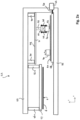
- an atomic force microscopy apparatus 23 comprises a metrology frame 25. Suspending from the metrology frame 25 is a sample carrier 27, which is attached to the metrology frame via a plurality of positioning actuators 26-1 and 26-2 for positioning the sample carrier 27 e.g. at a correct height level for performing measurements.
- the sample carrier 27 carries a wafer 6, the surface 5 of which has to be inspected by means of atomic force microscopy.
- the sample carrier may comprise different types of clamps such as suction clamps or mechanic clamps or the like.
- a support structure 48 holding a reference surface 50 comprising an optical reference grid is held in place underneath a manipulator 29.
- the manipulator 29 comprises a movable frame structure 30 including a rail 31.
- the movable frame structure 30 can be moved parallel to the reference surface 50, e.g. in a direction out of and in to the paper. This allows a manipulator arm 33 comprising a gripper 34 to reach any desired location on the reference surface 50 (as long as support structure 48 is positioned underneath the manipulator 29).
- the manipulator 29 allows to pick up each of a plurality of sensor heads 40 from a storage location, and place the respective head 40 onto a desired working position 52 on the reference surface 50. In figure 2a , one of the sensor heads 40 already resides in its desired working position on the reference surface 50, and the other sensor head 40 is being lowered towards the desired working position 52.
- the gripper 34 holds the sensor heads 40 by means of a clamping mechanism including clamping elements 35 and 36.
- the clamping elements 35 and 36 are rotatable fingers that can rotate around a hinge located at the base of gripper 34.
- the support stage 48 is self propelled, or can be hovered across the surface of the lower part 46 of the metrology frame 25 by means of an air bearing or magnetic levitation.
- the metrology frame 25 in its lower part 46 may comprise rails, with or without bearings, to move the support structure 48 to its second position.
- the skilled person may recognize alternative solutions that may be applied for moving the support structure 48, without departing from the invention.
- the support stage 48 is positioned in its second position underneath the sample carrier 27.
- a plurality of sensor heads 40 has been placed by the manipulator in a first position.
- the sensor heads can be placed by the manipulator in a very compact arrangement on the reference surface, and therefore the amount of sensor heads 40 located on the reference surface 50 may be much larger than as suggested in figure 2b .
- a dense arrangement of sensor heads 40 is also illustrated in figure 3 showing a reference surface 50 from above, wherein the sensor heads 40 are illustrated as squares. As can be seen, even in the dense arrangement illustrated in figure 3 , the density of the number of sensor heads 40 on the surface 50 of the wafer can be increased as long as the footprint for placing of the sensor heads 40 can be decreased.
- the support structure 48 is located underneath the sample carrier 27 carrying the wafer 6.
- each of the sensor heads 40 may comprise an additional piezo actuator which allows to adjust the z-position of the probe.
- the overall levelling of the whole wafer 6 relative to the sensor heads 40 may be adjusted by means of the actuators 26-1 and 26-2 of the sample carrier 27.
- the drawing of figure 2b is a two dimensional schematic drawings, and in reality a third or even a fourth adjustment actuator 26 may be used to generally align the wafer with the position of the probes or the sensor heads 40.
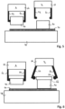
- FIG. 4 A plurality of different placement methods is schematically illustrated in figures 4 through 10 and will be discussed hereinbelow.
- Each of the figures 4 , 5 , 6 , 7 , 8 , 9b and 10 shows the gripper 34 of the manipulator 29 in a first mode A wherein it is holding the sensor head while placing it onto the surface 50, and in a second mode B wherein it has released the sensor head 40 in the correct working position 52.
- the manipulator may be arranged for moving either one or both of these elements.
- the manipulator may comprise an actuator for moving the gripper 34 or for moving the support structure 48 comprising reference surface 50, or both, in a direction parallel to the reference surface 50.
- the gripper 34 may be lowered towards the reference surface 50, or the support structure 48 comprising the reference surface 50 may be raised, in order to place the heads onto the reference surface 50.
- the skilled person is able to select a most suitable implementation of the invention without departing from the scope thereof.
- the gripper 34 comprises rotatable fingers 63 and 64.
- the fingers comprise structural elements such as ball contact 65 that cooperates with an edge or slot 66 on the sensor head 40. After placing of the sensor head, as illustrated in mode B, the fingers 63 and 64 rotate outward to release the sensor head 40 from the gripper 34.
- gripper 34 also comprises rotatable fingers 67 and 68, however these rotatable fingers 67 and 68 rotate slightly inwards after placing of the sensor head 40 in mode B.
- the engagement elements 69 at the ends of fingers 67 and 68 may for example cooperate with engagement openings in the upper part of the sensor head 40 to allow gripping by gripper 34.
- the gripper 34 also comprises fingers 70 and 71, which are connected to the gripper by means of releasable connections 73.
- the releasable connections 73 retain the end parts of fingers 70 and 71.
- the releasable connection 73 releases the clamping element 71 by means of mechanical contact transfer. Mechanical contact transfer relates to the actuation of an element responsive to a mechanical contact in a different part of that element or the device wherein it is implemented.
- the sensor head 40 touching the reference surface 50 changes the force equilibrium at the clamping element 71 and the releasable connection 73, such that the releasable connection 73 is released.
- element 73 may be a weak magnet, and the end of contact element 71 is slightly biased by means of a spring force in a direction pulling it away from releasable connection 73.
- the gravitational force is sufficiently strong for pulling the weakly biased contact element 71 towards the releasable connection 73, wherein it is held in place by the magnet.
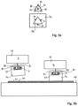
- FIG 9a a more sophisticated engagement element 81 is illustrated.
- Engagement element 81 suspends from a rotational extension arm 82.
- three slots 85, 86 and 87 In the corners of the triangular shaped engagement element 81, there is located three slots 85, 86 and 87.
- the upper part of sensor head 40 is also illustrated in figure 9a , comprising an engagement opening 80.
- the shape of the engagement opening 80 corresponds with the shape of the engagement element 81 in such a manner that the engagement element 81 fits through the engagement opening 80.
- three ball contacts 90, 91 and 92 are located on the periphery of the engagement opening 80 in the middle between the corners thereof.
- the slots 85, 86 and 87 align with the ball contacts 90, 91 and 92 respectively, and pulling the engagement element 81 upward will lift the sensor head 40.
- the ball of contacts 90, 91 and 92 and corresponding slots 85, 86 and 87 together form a kinematic mount which is designed for maintaining the sensor head 40 in place without over constraining or under constraining it in any dimension (x, y, z, Rx, Ry, Rz; wherein Rx through Rz are the rotation directions around axes parallel to the x, z, x axis).
- Figure 9b schematically illustrate how the cooperating engagements element 81 and engagement opening 80 work together to allow accurate placement of the sensor head 40 on the reference surface 50.
- gripper 34 has extended the engagement element 81 through the engagement opening 80, and it is held in place by means of the kinematic mount of which the ball contacts 91 and 92 are shown in the figure.
- the sensor head 40 is held in a slightly tilted manner such that one point of the sensor head 40 will first touch the reference surface 50.
- the first of the ball contacts 92 comes free from the slot 87.
- the three ball contacts 90, 91 and 92 will subsequently be released from the associated slots 85, 86 and 87.
- the gripper 34 comprises clamping elements consisting of a magnet 85 acting upon a counter element 96 held by the sensor head 40.
- the gripper 34 further comprises ball contacts 98, 99 (and a third ball contact (not shown)) falling into associated slots on the sensor head 40.
- magnet 95 is operated to release the sensor head.
- each of the contact elements 98 and 99 is magnetic, and can be released subsequently as is illustrated in figure 10 in mode B.
Landscapes
- Physics & Mathematics (AREA)
- Health & Medical Sciences (AREA)
- General Health & Medical Sciences (AREA)
- General Physics & Mathematics (AREA)
- Nuclear Medicine, Radiotherapy & Molecular Imaging (AREA)
- Radiology & Medical Imaging (AREA)
- Manipulator (AREA)
- Length Measuring Devices With Unspecified Measuring Means (AREA)
Claims (14)
- Vorrichtung (23) zum Messen und/oder Modifizieren von Oberflächenmerkmalen und/oder unter der Oberfläche liegenden Merkmalen auf oder unter einer Oberfläche (5) einer Probe (6), wobei die Vorrichtung Folgendes umfasst:einen Probenträger (27) zum Stützen der Probe (6), um die Oberfläche (5) freizulegen, um die Messung und/oder Modifizierung zu ermöglichen, einen oder mehrere Köpfe (40), die mindestens eine Oberflächenmesseinrichtung oder eine Oberflächenmodifikationseinrichtung umfassen, und eine Stützstruktur (48) zum Stützen des einen oder der mehreren Köpfe (40), wobei die Stützstruktur (48) eine Referenzoberfläche (50) zum Bereitstellen einer Positionierungsreferenz zum Ermöglichen der Positionierung jedes des einen oder der mehreren Köpfe (40) in einer jeweiligen Arbeitsposition umfasst,wobei die Köpfe (40) von dem Probenträger (27) und der Stützstruktur (48) getrennt sind, so dass sie nicht mit diesen verbunden sind, und wobei die Vorrichtung (23) ferner einen Aufnahme-und-Absetz-Manipulator umfasst, der zum Greifen der jeweiligen Köpfe (40) und zum Positionieren derselben auf der Referenzoberfläche (50) in ihren jeweiligen Arbeitspositionen angeordnet ist,wobei die Referenzoberfläche ein optisches Referenzgitter umfasst, und wobei der Manipulator einen Greifer (34) und einen Aktuator zum Bewegen des Greifers (34) und der Referenzoberfläche (50) relativ zueinander umfasst, wobei der Aktuator so angeordnet ist, dass er eine Bewegung in einer Richtung quer zur Referenzoberfläche (50) erzeugt, und wobei der Greifer (34) angeordnet ist, um die jeweiligen Köpfe (40) aus der Querbewegung zu ergreifen und freizugeben, um die Köpfe (40) auf sie Referenzoberfläche (50) zu setzen,wobei der Greifer (34) und die Köpfe (40) eine gegenseitig zusammenwirkende Eingriffsstruktur umfassen, die eine kinematische Halterung bildet, die kinematische Halterung mindestens drei Strukturelemente umfasst, die entweder auf dem Greifer (34) oder den Köpfen (40) angeordnet sind, wobei die mindestens drei Strukturelemente mit mindestens drei Schlitzen zusammenwirken, die an einem anderen der Greifer (34) oder der Köpfe (40) angeordnet sind.
- Vorrichtung (23) nach Anspruch 1, wobei die Stützstruktur (48) relativ zum Probenträger (27) zumindest in einer Richtung parallel zur Referenzoberfläche (50) beweglich ist, wobei die Vorrichtung (23) ferner einen Stufenaktuator zum Bewegen der Stützstruktur (48) relativ zu dem Probenträger (27) und dem Manipulator umfasst, wobei der Stufenaktuator so angeordnet ist, dass es die Stützstruktur (48) zwischen mindestens einer ersten Position, die das Messen und/oder Ändern der Oberflächenmerkmale ermöglicht, und einer zweiten Position, die das Aufsetzen und Entfernen der Köpfe (40) auf und von den Arbeitspositionen ermöglicht, bewegt.
- Vorrichtung (23) nach Anspruch 1 oder 2, dadurch gekennzeichnet, dass sie in die jeweiligen Köpfe (40) eingreift, der Greifer (34) mindestens eines der folgenden Elemente umfasst: Spannelemente wie Saugspanner, Magnetspannelemente, elektrostatische Spannelemente oder flexible Spannelemente, flexible oder drehbare Greiffinger; oder auf Schwerkraft basierende Eingriffselemente, wie z. B. strukturelle Merkmale, ein Steg, ein Haken, eine Kante, ein Schlitz, zum Zusammenwirken mit einer Struktur der jeweiligen Köpfe (40).
- Vorrichtung (23) nach einem der vorhergehenden Ansprüche, wobei der eine oder die mehreren Köpfe (40) mindestens eine Eingriffsöffnung oder ein Eingriffselement (81) umfassen, wobei die Eingriffsöffnung (80) oder das Eingriffselement (81) an einer Oberseite der Köpfe (40) angeordnet ist, und wobei der Greifer (34) mindestens eine weitere Eingriffsöffnung (80) oder ein weiteres Eingriffselement (81) umfasst, wobei die Eingriffsöffnung (80) und das Eingriffselement (81) einander so entsprechen, dass sie die Aufnahme des Eingriffselements (81) in der Eingriffsöffnung (80) ermöglichen, um das Eingreifen zu ermöglichen.
- Vorrichtung (23) nach Anspruch 4, wobei der Greifer (34) eine drehbare Verlängerung (67, 68, 82) mit dem Eingriffselement (81) umfasst, und wobei das Eingriffselement (81) und die Eingriffsöffnung (80) entsprechend so geformt sind, dass das Eingriffselement (81) in einer ersten Drehposition des Eingriffselements (81) durch die Eingriffsöffnung (80) passt, während es in einer zweiten Drehposition des Eingriffselements (81) das Eingreifen ermöglicht.
- Vorrichtung (23) nach Anspruch 5, wobei das Eingriffselement (81) und die Eingriffsöffnung (80) die Form eines Vielecks, wie eines Dreiecks, eines Quadrats oder Rechtecks, eines Fünfecks, eines Sechsecks, eines Heptagons, eines Achtecks oder eines anderen Vielecks haben.
- Vorrichtung (23) nach Anspruch 6, wobei die mindestens drei Strukturelemente oder mindestens drei Schlitze in einer oder mehreren Ecken der Polygonform des Eingriffselements (81) und der Eingriffsöffnung (80) angeordnet sind.
- Vorrichtung (23) nach einem der vorhergehenden Ansprüche, wobei der Greifer (34) so angeordnet ist, dass er die Köpfe (40) während der Bewegung der Köpfe (40) auf die Stützstruktur (48) zu und von ihr weg in einer geneigten Ausrichtung relativ zur Referenzoberfläche (50) hält.
- Vorrichtung (23) nach Anspruch 8, wobei der Greifer (34) drei Finger umfasst, wobei jeder Finger ein Klemmelement umfasst, um einen Kontaktpunkt mit einem entsprechenden Kopf (40) während des Eingriffs zu definieren, wobei jeder dieser Finger über eine lösbare Verbindung mit dem Greifer (34) verbunden ist, wobei die lösbare Verbindung über eine mechanische Kontaktübertragung durch den jeweiligen Finger betätigt werden kann, um eine Fixierung oder Bewegung des Fingers in Bezug auf den Greifer (34) in Abhängigkeit vom Kontakt des jeweiligen Kopfes (40) mit der Stützstruktur (48) zu ermöglichen.
- Vorrichtung (23) nach Anspruch 9, wobei die lösbare Verbindung ein magnetisches Element umfasst.
- Vorrichtung (23) nach einem der vorhergehenden Ansprüche, wobei die Vorrichtung eine Rastersondenmikroskopievorrichtung (23), wie z.B. eine Rasterkraftmikroskopievorrichtung, ist.
- Verfahren zum Messen und/oder Modifizieren von Oberflächenmerkmalen und/oder unter der Oberfläche liegenden Merkmalen auf oder unter einer Oberfläche (5) einer Probe (6), wobei das Verfahren unter Verwendung einer Vorrichtung (23) durchgeführt wird, die Folgendes umfasst:einen Probenträger (27) zum Tragen der Probe (6), eine Stützstruktur (48) umfassend eine Referenzoberfläche (50), wobei die Referenzoberfläche (50) ein optisches Referenzgitter umfasst, und einen oder mehrere Köpfe (40), die mindestens eine Oberflächenmesseinrichtung oder eine Oberflächenmodifikationseinrichtung umfassen, wobei die Köpfe (40) von dem Probenträger (27) und der Stützstruktur (48) getrennt sind;wobei das Verfahren umfasst:Aufsetzen des einen oder der mehreren Köpfe (40) unter Verwendung eines Aufnahme-und-Absetz-Manipulators an einer Vielzahl von Arbeitspositionen auf der Stützstruktur (48); undDurchführen der Messung und/oder Modifizierung von Oberflächenmerkmalen durch die Oberflächenmessgeräte oder Oberflächenmodifizierungsgeräte an den Köpfen (40);wobei der Schritt des Aufsetzens des einen oder der mehreren Köpfe (40) umfasst:mit einem Greifer (34) in einen der Köpfe (40) eingreifen; Bewegen des Greifers (34) und der Referenzfläche (50) relativ zueinander unter Verwendung eines Aktuators des Manipulators in einer Richtung quer zur Referenzoberfläche (50); undLösen der jeweiligen Köpfe (40) vom Greifer (34) an den jeweiligen Arbeitspositionen, um die Köpfe (40) auf der Referenzoberfläche (50) aufzusetzen,wobei der Schritt des Aufsetzens unter Verwendung einer kinematischen Halterung durchgeführt wird, wobei der Greifer (34) und die Köpfe (40) eine gegenseitig zusammenwirkende Eingriffsstruktur umfassen, die die kinematische Halterung bildet, die kinematische Halterung mindestens drei Strukturelemente umfasst, die entweder am Greifer (34) oder an den Köpfen (40) angeordnet sind, wobei die mindestens drei Strukturelemente mit mindestens drei Schlitzen zusammenwirken, die an einem anderen der Greifer (34) oder der Köpfe (40) angeordnet sind.
- Verfahren nach Anspruch 12, das ferner umfasst, dass vor dem Schritt der Durchführung der Messung oder der Veränderung der Oberflächenmerkmale eine Bewegung der Stützstruktur (48) relativ zum Probenträger (27) in einer Richtung parallel zur Referenzoberfläche (50) unter Verwendung eines Stufenaktuators erfolgt, wobei diese Bewegung zwischen mindestens einer ersten Position, die die Messung und/oder Veränderung der Oberflächenmerkmale ermöglicht, und einer zweiten Position, die das Aufsetzen und Entfernen der Köpfe (40) auf und von den Arbeitspositionen ermöglicht, durchgeführt wird.
- Verfahren nach Anspruch 12 oder 13, wobei der Schritt des Eingreifens die Aufnahme eines Eingriffselements (81) von mindestens einem der Greifer (34) oder des jeweiligen Kopfes (40) in einer entsprechend geformten Eingriffsöffnung (80) in einem anderen der Greifer (34) oder des jeweiligen Kopfes (40) umfasst, wobei sich das jeweilige Eingriffselement (81) oder die Eingriffsöffnung an einer Oberseite der Köpfe (40) befindet.
Applications Claiming Priority (2)
| Application Number | Priority Date | Filing Date | Title |
|---|---|---|---|
| EP15181585.9A EP3133404A1 (de) | 2015-08-19 | 2015-08-19 | Vorrichtung und verfahren zur messung und/oder modifizierung von oberflächenmerkmalen an der oberfläche einer probe |
| PCT/NL2016/050582 WO2017030441A1 (en) | 2015-08-19 | 2016-08-18 | Device and method for measuring and/or modifying surface features on a surface of a sample. |
Publications (2)
| Publication Number | Publication Date |
|---|---|
| EP3338098A1 EP3338098A1 (de) | 2018-06-27 |
| EP3338098B1 true EP3338098B1 (de) | 2025-06-25 |
Family
ID=54072656
Family Applications (2)
| Application Number | Title | Priority Date | Filing Date |
|---|---|---|---|
| EP15181585.9A Withdrawn EP3133404A1 (de) | 2015-08-19 | 2015-08-19 | Vorrichtung und verfahren zur messung und/oder modifizierung von oberflächenmerkmalen an der oberfläche einer probe |
| EP16760819.9A Active EP3338098B1 (de) | 2015-08-19 | 2016-08-18 | Vorrichtung und verfahren zur messung und/oder modifizierung von oberflächenmerkmalen an der oberfläche einer probe |
Family Applications Before (1)
| Application Number | Title | Priority Date | Filing Date |
|---|---|---|---|
| EP15181585.9A Withdrawn EP3133404A1 (de) | 2015-08-19 | 2015-08-19 | Vorrichtung und verfahren zur messung und/oder modifizierung von oberflächenmerkmalen an der oberfläche einer probe |
Country Status (5)
| Country | Link |
|---|---|
| US (1) | US10908179B2 (de) |
| EP (2) | EP3133404A1 (de) |
| KR (1) | KR102700828B1 (de) |
| TW (1) | TWI718174B (de) |
| WO (1) | WO2017030441A1 (de) |
Families Citing this family (6)
| Publication number | Priority date | Publication date | Assignee | Title |
|---|---|---|---|---|
| CN107302103B (zh) * | 2017-08-14 | 2023-03-03 | 福建亚南电机有限公司 | 一种pemfc电堆自动化装配系统 |
| KR102026665B1 (ko) * | 2018-06-18 | 2019-09-30 | 한국표준과학연구원 | 원자간력 현미경 시료와 탐침 사이의 위치조절을 위한 시료 스테이지 시스템 및 그를 이용한 관찰방법 |
| CN110963489B (zh) * | 2018-09-28 | 2023-07-28 | 贝特瑞新材料集团股份有限公司 | 一种碳负极材料及其制备方法和锂离子电池 |
| CN112781759B (zh) * | 2019-11-07 | 2023-01-20 | 清华大学 | 一种压力传感器及其制备方法 |
| CN111220309B (zh) * | 2020-03-27 | 2020-07-21 | 广东省计量科学研究院(华南国家计量测试中心) | 一种用于微纳力测量的力源装置及其实现方法 |
| CN111407651B (zh) * | 2020-03-31 | 2025-09-12 | 吴彩芳 | 一种穿刺机头 |
Family Cites Families (10)
| Publication number | Priority date | Publication date | Assignee | Title |
|---|---|---|---|---|
| GB2235571B (en) * | 1989-06-26 | 1993-11-17 | Jeol Ltd | Scanning tunnelling microscope |
| US5679952A (en) * | 1994-05-23 | 1997-10-21 | Hitachi, Ltd. | Scanning probe microscope |
| JP3425383B2 (ja) * | 1998-12-03 | 2003-07-14 | 株式会社島津製作所 | 走査型プローブ顕微鏡及びプローブホルダ |
| JP2001235416A (ja) * | 2000-02-24 | 2001-08-31 | Matsushita Electric Ind Co Ltd | 走査型プローブ顕微鏡および試料・プローブ交換方法 |
| TWI228174B (en) * | 2003-09-30 | 2005-02-21 | Gallant Prec Machining Co Ltd | Nanometer mechanical measurement device with a high-strength probe |
| EP1995737A1 (de) * | 2007-05-25 | 2008-11-26 | Institut de Microtechnique de l'Université de Neuchâtel | Sondenmodul, Sondenarray und Verfahren zur Montage von Sondenarrays |
| TWI421490B (zh) | 2010-03-17 | 2014-01-01 | Univ Nat Sun Yat Sen | 偵測與顯像磁性金屬蛋白之方法 |
| EP2867683B1 (de) * | 2012-06-28 | 2021-09-01 | Nederlandse Organisatie voor toegepast- natuurwetenschappelijk onderzoek TNO | Mikroskopievorrichtung mit hohem durchlauf |
| EP2682759A1 (de) * | 2012-07-06 | 2014-01-08 | Nederlandse Organisatie voor toegepast -natuurwetenschappelijk onderzoek TNO | Mikroskopievorrichtung mit hohem Durchlauf |
| GB201314302D0 (en) * | 2013-08-09 | 2013-09-25 | Infinitesima Ltd | Probe and sample exchange mechanism |
-
2015
- 2015-08-19 EP EP15181585.9A patent/EP3133404A1/de not_active Withdrawn
-
2016
- 2016-08-16 TW TW105126117A patent/TWI718174B/zh active
- 2016-08-18 WO PCT/NL2016/050582 patent/WO2017030441A1/en not_active Ceased
- 2016-08-18 KR KR1020187006924A patent/KR102700828B1/ko active Active
- 2016-08-18 EP EP16760819.9A patent/EP3338098B1/de active Active
- 2016-08-18 US US15/753,094 patent/US10908179B2/en active Active
Also Published As
| Publication number | Publication date |
|---|---|
| KR20180039694A (ko) | 2018-04-18 |
| EP3338098A1 (de) | 2018-06-27 |
| US10908179B2 (en) | 2021-02-02 |
| TWI718174B (zh) | 2021-02-11 |
| US20180238931A1 (en) | 2018-08-23 |
| KR102700828B1 (ko) | 2024-08-30 |
| EP3133404A1 (de) | 2017-02-22 |
| TW201723486A (zh) | 2017-07-01 |
| WO2017030441A1 (en) | 2017-02-23 |
Similar Documents
| Publication | Publication Date | Title |
|---|---|---|
| EP3338098B1 (de) | Vorrichtung und verfahren zur messung und/oder modifizierung von oberflächenmerkmalen an der oberfläche einer probe | |
| JP5678156B2 (ja) | ナノメカニカルテストシステム | |
| EP2867682B1 (de) | Scansonden-mikroskopievorrichtung mit hohem durchlauf | |
| KR101474576B1 (ko) | 스캐닝 탐침 현미경용 탐침 조립체 | |
| Xie et al. | Development of a flexible robotic system for multiscale applications of micro/nanoscale manipulation and assembly | |
| EP2682759A1 (de) | Mikroskopievorrichtung mit hohem Durchlauf | |
| EP2867683B1 (de) | Mikroskopievorrichtung mit hohem durchlauf | |
| TWI676030B (zh) | 在基板表面操作掃描探測顯微鏡之系統及方法 | |
| JP2006275826A (ja) | 表面形状測定装置 | |
| EP3322993B1 (de) | Rastersondenmikroskopiesystem zum abbilden von nanostrukturen auf der oberfläche einer probe und metrologierahmen dafür | |
| WO2017079375A1 (en) | Metrology devices and methods for independently controlling a plurality of sensing probes | |
| Fatikow et al. | Depth-detection methods for CNT manipulation and characterization in a scanning electron microscope | |
| US10649003B2 (en) | Coupled multiscale positioning of arrays of parallel, independently actuated and simultaneously driven modular scanning probe microscopes for high-throughput, in-line, nanoscale measurement of flexible, large area, and roll-to-roll processes | |
| US10712364B2 (en) | Metrology devices for rapid specimen setup | |
| CN121784047A (zh) | 一种具备清洁和测试功能的集成纳米探针 | |
| JPH0835972A (ja) | 簡易型spm装置 | |
| Xie et al. | Applications of AFM based nanorobotic systems | |
| JP4130169B2 (ja) | 走査型プローブ顕微鏡 | |
| Zhang | MEMS and Robotics-based Manipulation and Characterization of Micro and Nanomaterials |
Legal Events
| Date | Code | Title | Description |
|---|---|---|---|
| STAA | Information on the status of an ep patent application or granted ep patent |
Free format text: STATUS: THE INTERNATIONAL PUBLICATION HAS BEEN MADE |
|
| PUAI | Public reference made under article 153(3) epc to a published international application that has entered the european phase |
Free format text: ORIGINAL CODE: 0009012 |
|
| STAA | Information on the status of an ep patent application or granted ep patent |
Free format text: STATUS: REQUEST FOR EXAMINATION WAS MADE |
|
| 17P | Request for examination filed |
Effective date: 20180309 |
|
| AK | Designated contracting states |
Kind code of ref document: A1 Designated state(s): AL AT BE BG CH CY CZ DE DK EE ES FI FR GB GR HR HU IE IS IT LI LT LU LV MC MK MT NL NO PL PT RO RS SE SI SK SM TR |
|
| AX | Request for extension of the european patent |
Extension state: BA ME |
|
| DAV | Request for validation of the european patent (deleted) | ||
| DAX | Request for extension of the european patent (deleted) | ||
| STAA | Information on the status of an ep patent application or granted ep patent |
Free format text: STATUS: EXAMINATION IS IN PROGRESS |
|
| 17Q | First examination report despatched |
Effective date: 20210120 |
|
| P01 | Opt-out of the competence of the unified patent court (upc) registered |
Effective date: 20230522 |
|
| GRAP | Despatch of communication of intention to grant a patent |
Free format text: ORIGINAL CODE: EPIDOSNIGR1 |
|
| STAA | Information on the status of an ep patent application or granted ep patent |
Free format text: STATUS: GRANT OF PATENT IS INTENDED |
|
| INTG | Intention to grant announced |
Effective date: 20241028 |
|
| GRAJ | Information related to disapproval of communication of intention to grant by the applicant or resumption of examination proceedings by the epo deleted |
Free format text: ORIGINAL CODE: EPIDOSDIGR1 |
|
| STAA | Information on the status of an ep patent application or granted ep patent |
Free format text: STATUS: EXAMINATION IS IN PROGRESS |
|
| GRAS | Grant fee paid |
Free format text: ORIGINAL CODE: EPIDOSNIGR3 |
|
| STAA | Information on the status of an ep patent application or granted ep patent |
Free format text: STATUS: GRANT OF PATENT IS INTENDED |
|
| GRAP | Despatch of communication of intention to grant a patent |
Free format text: ORIGINAL CODE: EPIDOSNIGR1 |
|
| INTC | Intention to grant announced (deleted) | ||
| INTG | Intention to grant announced |
Effective date: 20250207 |
|
| GRAA | (expected) grant |
Free format text: ORIGINAL CODE: 0009210 |
|
| STAA | Information on the status of an ep patent application or granted ep patent |
Free format text: STATUS: THE PATENT HAS BEEN GRANTED |
|
| AK | Designated contracting states |
Kind code of ref document: B1 Designated state(s): AL AT BE BG CH CY CZ DE DK EE ES FI FR GB GR HR HU IE IS IT LI LT LU LV MC MK MT NL NO PL PT RO RS SE SI SK SM TR |
|
| REG | Reference to a national code |
Ref country code: GB Ref legal event code: FG4D |
|
| REG | Reference to a national code |
Ref country code: CH Ref legal event code: EP |
|
| REG | Reference to a national code |
Ref country code: DE Ref legal event code: R096 Ref document number: 602016092662 Country of ref document: DE |
|
| REG | Reference to a national code |
Ref country code: CH Ref legal event code: EP |
|
| REG | Reference to a national code |
Ref country code: IE Ref legal event code: FG4D |
|
| PG25 | Lapsed in a contracting state [announced via postgrant information from national office to epo] |
Ref country code: FI Free format text: LAPSE BECAUSE OF FAILURE TO SUBMIT A TRANSLATION OF THE DESCRIPTION OR TO PAY THE FEE WITHIN THE PRESCRIBED TIME-LIMIT Effective date: 20250625 |
|
| PGFP | Annual fee paid to national office [announced via postgrant information from national office to epo] |
Ref country code: DE Payment date: 20250828 Year of fee payment: 10 |
|
| REG | Reference to a national code |
Ref country code: LT Ref legal event code: MG9D |
|
| PG25 | Lapsed in a contracting state [announced via postgrant information from national office to epo] |
Ref country code: GR Free format text: LAPSE BECAUSE OF FAILURE TO SUBMIT A TRANSLATION OF THE DESCRIPTION OR TO PAY THE FEE WITHIN THE PRESCRIBED TIME-LIMIT Effective date: 20250926 Ref country code: NO Free format text: LAPSE BECAUSE OF FAILURE TO SUBMIT A TRANSLATION OF THE DESCRIPTION OR TO PAY THE FEE WITHIN THE PRESCRIBED TIME-LIMIT Effective date: 20250925 |
|
| PGFP | Annual fee paid to national office [announced via postgrant information from national office to epo] |
Ref country code: NL Payment date: 20250829 Year of fee payment: 10 |
|
| REG | Reference to a national code |
Ref country code: NL Ref legal event code: FP |
|
| PG25 | Lapsed in a contracting state [announced via postgrant information from national office to epo] |
Ref country code: BG Free format text: LAPSE BECAUSE OF FAILURE TO SUBMIT A TRANSLATION OF THE DESCRIPTION OR TO PAY THE FEE WITHIN THE PRESCRIBED TIME-LIMIT Effective date: 20250625 |
|
| PG25 | Lapsed in a contracting state [announced via postgrant information from national office to epo] |
Ref country code: HR Free format text: LAPSE BECAUSE OF FAILURE TO SUBMIT A TRANSLATION OF THE DESCRIPTION OR TO PAY THE FEE WITHIN THE PRESCRIBED TIME-LIMIT Effective date: 20250625 |
|
| PGFP | Annual fee paid to national office [announced via postgrant information from national office to epo] |
Ref country code: FR Payment date: 20250829 Year of fee payment: 10 |
|
| PG25 | Lapsed in a contracting state [announced via postgrant information from national office to epo] |
Ref country code: RS Free format text: LAPSE BECAUSE OF FAILURE TO SUBMIT A TRANSLATION OF THE DESCRIPTION OR TO PAY THE FEE WITHIN THE PRESCRIBED TIME-LIMIT Effective date: 20250925 |
|
| PGFP | Annual fee paid to national office [announced via postgrant information from national office to epo] |
Ref country code: IE Payment date: 20250829 Year of fee payment: 10 |
|
| PG25 | Lapsed in a contracting state [announced via postgrant information from national office to epo] |
Ref country code: LV Free format text: LAPSE BECAUSE OF FAILURE TO SUBMIT A TRANSLATION OF THE DESCRIPTION OR TO PAY THE FEE WITHIN THE PRESCRIBED TIME-LIMIT Effective date: 20250625 |
|
| PG25 | Lapsed in a contracting state [announced via postgrant information from national office to epo] |
Ref country code: PT Free format text: LAPSE BECAUSE OF FAILURE TO SUBMIT A TRANSLATION OF THE DESCRIPTION OR TO PAY THE FEE WITHIN THE PRESCRIBED TIME-LIMIT Effective date: 20251027 |
|
| REG | Reference to a national code |
Ref country code: AT Ref legal event code: MK05 Ref document number: 1806965 Country of ref document: AT Kind code of ref document: T Effective date: 20250625 |
|
| PG25 | Lapsed in a contracting state [announced via postgrant information from national office to epo] |
Ref country code: IS Free format text: LAPSE BECAUSE OF FAILURE TO SUBMIT A TRANSLATION OF THE DESCRIPTION OR TO PAY THE FEE WITHIN THE PRESCRIBED TIME-LIMIT Effective date: 20251025 |
|
| PG25 | Lapsed in a contracting state [announced via postgrant information from national office to epo] |
Ref country code: AT Free format text: LAPSE BECAUSE OF FAILURE TO SUBMIT A TRANSLATION OF THE DESCRIPTION OR TO PAY THE FEE WITHIN THE PRESCRIBED TIME-LIMIT Effective date: 20250625 Ref country code: SM Free format text: LAPSE BECAUSE OF FAILURE TO SUBMIT A TRANSLATION OF THE DESCRIPTION OR TO PAY THE FEE WITHIN THE PRESCRIBED TIME-LIMIT Effective date: 20250625 |
|
| PG25 | Lapsed in a contracting state [announced via postgrant information from national office to epo] |
Ref country code: CZ Free format text: LAPSE BECAUSE OF FAILURE TO SUBMIT A TRANSLATION OF THE DESCRIPTION OR TO PAY THE FEE WITHIN THE PRESCRIBED TIME-LIMIT Effective date: 20250625 |
|
| PG25 | Lapsed in a contracting state [announced via postgrant information from national office to epo] |
Ref country code: PL Free format text: LAPSE BECAUSE OF FAILURE TO SUBMIT A TRANSLATION OF THE DESCRIPTION OR TO PAY THE FEE WITHIN THE PRESCRIBED TIME-LIMIT Effective date: 20250625 |
|
| PG25 | Lapsed in a contracting state [announced via postgrant information from national office to epo] |
Ref country code: EE Free format text: LAPSE BECAUSE OF FAILURE TO SUBMIT A TRANSLATION OF THE DESCRIPTION OR TO PAY THE FEE WITHIN THE PRESCRIBED TIME-LIMIT Effective date: 20250625 |
|
| PG25 | Lapsed in a contracting state [announced via postgrant information from national office to epo] |
Ref country code: SK Free format text: LAPSE BECAUSE OF FAILURE TO SUBMIT A TRANSLATION OF THE DESCRIPTION OR TO PAY THE FEE WITHIN THE PRESCRIBED TIME-LIMIT Effective date: 20250625 Ref country code: RO Free format text: LAPSE BECAUSE OF FAILURE TO SUBMIT A TRANSLATION OF THE DESCRIPTION OR TO PAY THE FEE WITHIN THE PRESCRIBED TIME-LIMIT Effective date: 20250625 |
|
| PG25 | Lapsed in a contracting state [announced via postgrant information from national office to epo] |
Ref country code: ES Free format text: LAPSE BECAUSE OF FAILURE TO SUBMIT A TRANSLATION OF THE DESCRIPTION OR TO PAY THE FEE WITHIN THE PRESCRIBED TIME-LIMIT Effective date: 20250625 |
|
| REG | Reference to a national code |
Ref country code: CH Ref legal event code: H13 Free format text: ST27 STATUS EVENT CODE: U-0-0-H10-H13 (AS PROVIDED BY THE NATIONAL OFFICE) Effective date: 20260324 |
|
| PG25 | Lapsed in a contracting state [announced via postgrant information from national office to epo] |
Ref country code: MC Free format text: LAPSE BECAUSE OF FAILURE TO SUBMIT A TRANSLATION OF THE DESCRIPTION OR TO PAY THE FEE WITHIN THE PRESCRIBED TIME-LIMIT Effective date: 20250625 |
|
| PG25 | Lapsed in a contracting state [announced via postgrant information from national office to epo] |
Ref country code: DK Free format text: LAPSE BECAUSE OF FAILURE TO SUBMIT A TRANSLATION OF THE DESCRIPTION OR TO PAY THE FEE WITHIN THE PRESCRIBED TIME-LIMIT Effective date: 20250625 |
|
| PG25 | Lapsed in a contracting state [announced via postgrant information from national office to epo] |
Ref country code: LU Free format text: LAPSE BECAUSE OF NON-PAYMENT OF DUE FEES Effective date: 20250818 Ref country code: IT Free format text: LAPSE BECAUSE OF FAILURE TO SUBMIT A TRANSLATION OF THE DESCRIPTION OR TO PAY THE FEE WITHIN THE PRESCRIBED TIME-LIMIT Effective date: 20250625 |