EP3336378B1 - Mittelpunkt suchendes stellglied - Google Patents
Mittelpunkt suchendes stellglied Download PDFInfo
- Publication number
- EP3336378B1 EP3336378B1 EP16205169.2A EP16205169A EP3336378B1 EP 3336378 B1 EP3336378 B1 EP 3336378B1 EP 16205169 A EP16205169 A EP 16205169A EP 3336378 B1 EP3336378 B1 EP 3336378B1
- Authority
- EP
- European Patent Office
- Prior art keywords
- outer cylinder
- actuator
- slave cylinder
- assembly
- cylinder
- Prior art date
- Legal status (The legal status is an assumption and is not a legal conclusion. Google has not performed a legal analysis and makes no representation as to the accuracy of the status listed.)
- Active
Links
Images


Classifications
-
- F—MECHANICAL ENGINEERING; LIGHTING; HEATING; WEAPONS; BLASTING
- F15—FLUID-PRESSURE ACTUATORS; HYDRAULICS OR PNEUMATICS IN GENERAL
- F15B—SYSTEMS ACTING BY MEANS OF FLUIDS IN GENERAL; FLUID-PRESSURE ACTUATORS, e.g. SERVOMOTORS; DETAILS OF FLUID-PRESSURE SYSTEMS, NOT OTHERWISE PROVIDED FOR
- F15B15/00—Fluid-actuated devices for displacing a member from one position to another; Gearing associated therewith
- F15B15/08—Characterised by the construction of the motor unit
- F15B15/14—Characterised by the construction of the motor unit of the straight-cylinder type
- F15B15/16—Characterised by the construction of the motor unit of the straight-cylinder type of the telescopic type
-
- B—PERFORMING OPERATIONS; TRANSPORTING
- B64—AIRCRAFT; AVIATION; COSMONAUTICS
- B64C—AEROPLANES; HELICOPTERS
- B64C25/00—Alighting gear
- B64C25/32—Alighting gear characterised by elements which contact the ground or similar surface
- B64C25/58—Arrangements or adaptations of shock-absorbers or springs
-
- F—MECHANICAL ENGINEERING; LIGHTING; HEATING; WEAPONS; BLASTING
- F15—FLUID-PRESSURE ACTUATORS; HYDRAULICS OR PNEUMATICS IN GENERAL
- F15B—SYSTEMS ACTING BY MEANS OF FLUIDS IN GENERAL; FLUID-PRESSURE ACTUATORS, e.g. SERVOMOTORS; DETAILS OF FLUID-PRESSURE SYSTEMS, NOT OTHERWISE PROVIDED FOR
- F15B15/00—Fluid-actuated devices for displacing a member from one position to another; Gearing associated therewith
- F15B15/08—Characterised by the construction of the motor unit
- F15B15/14—Characterised by the construction of the motor unit of the straight-cylinder type
- F15B15/1423—Component parts; Constructional details
- F15B15/1428—Cylinders
-
- F—MECHANICAL ENGINEERING; LIGHTING; HEATING; WEAPONS; BLASTING
- F15—FLUID-PRESSURE ACTUATORS; HYDRAULICS OR PNEUMATICS IN GENERAL
- F15B—SYSTEMS ACTING BY MEANS OF FLUIDS IN GENERAL; FLUID-PRESSURE ACTUATORS, e.g. SERVOMOTORS; DETAILS OF FLUID-PRESSURE SYSTEMS, NOT OTHERWISE PROVIDED FOR
- F15B15/00—Fluid-actuated devices for displacing a member from one position to another; Gearing associated therewith
- F15B15/08—Characterised by the construction of the motor unit
- F15B15/14—Characterised by the construction of the motor unit of the straight-cylinder type
- F15B15/1423—Component parts; Constructional details
- F15B15/1438—Cylinder to end cap assemblies
-
- F—MECHANICAL ENGINEERING; LIGHTING; HEATING; WEAPONS; BLASTING
- F15—FLUID-PRESSURE ACTUATORS; HYDRAULICS OR PNEUMATICS IN GENERAL
- F15B—SYSTEMS ACTING BY MEANS OF FLUIDS IN GENERAL; FLUID-PRESSURE ACTUATORS, e.g. SERVOMOTORS; DETAILS OF FLUID-PRESSURE SYSTEMS, NOT OTHERWISE PROVIDED FOR
- F15B15/00—Fluid-actuated devices for displacing a member from one position to another; Gearing associated therewith
- F15B15/08—Characterised by the construction of the motor unit
- F15B15/14—Characterised by the construction of the motor unit of the straight-cylinder type
- F15B15/1423—Component parts; Constructional details
- F15B15/1447—Pistons; Piston to piston rod assemblies
- F15B15/1452—Piston sealings
-
- F—MECHANICAL ENGINEERING; LIGHTING; HEATING; WEAPONS; BLASTING
- F15—FLUID-PRESSURE ACTUATORS; HYDRAULICS OR PNEUMATICS IN GENERAL
- F15B—SYSTEMS ACTING BY MEANS OF FLUIDS IN GENERAL; FLUID-PRESSURE ACTUATORS, e.g. SERVOMOTORS; DETAILS OF FLUID-PRESSURE SYSTEMS, NOT OTHERWISE PROVIDED FOR
- F15B15/00—Fluid-actuated devices for displacing a member from one position to another; Gearing associated therewith
- F15B15/08—Characterised by the construction of the motor unit
- F15B15/14—Characterised by the construction of the motor unit of the straight-cylinder type
- F15B15/1423—Component parts; Constructional details
- F15B15/1457—Piston rods
- F15B15/1461—Piston rod sealings
-
- F—MECHANICAL ENGINEERING; LIGHTING; HEATING; WEAPONS; BLASTING
- F15—FLUID-PRESSURE ACTUATORS; HYDRAULICS OR PNEUMATICS IN GENERAL
- F15B—SYSTEMS ACTING BY MEANS OF FLUIDS IN GENERAL; FLUID-PRESSURE ACTUATORS, e.g. SERVOMOTORS; DETAILS OF FLUID-PRESSURE SYSTEMS, NOT OTHERWISE PROVIDED FOR
- F15B15/00—Fluid-actuated devices for displacing a member from one position to another; Gearing associated therewith
- F15B15/08—Characterised by the construction of the motor unit
- F15B15/14—Characterised by the construction of the motor unit of the straight-cylinder type
- F15B15/1423—Component parts; Constructional details
- F15B15/1476—Special return means
-
- F—MECHANICAL ENGINEERING; LIGHTING; HEATING; WEAPONS; BLASTING
- F15—FLUID-PRESSURE ACTUATORS; HYDRAULICS OR PNEUMATICS IN GENERAL
- F15B—SYSTEMS ACTING BY MEANS OF FLUIDS IN GENERAL; FLUID-PRESSURE ACTUATORS, e.g. SERVOMOTORS; DETAILS OF FLUID-PRESSURE SYSTEMS, NOT OTHERWISE PROVIDED FOR
- F15B15/00—Fluid-actuated devices for displacing a member from one position to another; Gearing associated therewith
- F15B15/08—Characterised by the construction of the motor unit
- F15B15/14—Characterised by the construction of the motor unit of the straight-cylinder type
- F15B15/149—Fluid interconnections, e.g. fluid connectors, passages
-
- F—MECHANICAL ENGINEERING; LIGHTING; HEATING; WEAPONS; BLASTING
- F15—FLUID-PRESSURE ACTUATORS; HYDRAULICS OR PNEUMATICS IN GENERAL
- F15B—SYSTEMS ACTING BY MEANS OF FLUIDS IN GENERAL; FLUID-PRESSURE ACTUATORS, e.g. SERVOMOTORS; DETAILS OF FLUID-PRESSURE SYSTEMS, NOT OTHERWISE PROVIDED FOR
- F15B15/00—Fluid-actuated devices for displacing a member from one position to another; Gearing associated therewith
- F15B15/20—Other details, e.g. assembly with regulating devices
- F15B15/24—Other details, e.g. assembly with regulating devices for restricting the stroke
-
- F—MECHANICAL ENGINEERING; LIGHTING; HEATING; WEAPONS; BLASTING
- F16—ENGINEERING ELEMENTS AND UNITS; GENERAL MEASURES FOR PRODUCING AND MAINTAINING EFFECTIVE FUNCTIONING OF MACHINES OR INSTALLATIONS; THERMAL INSULATION IN GENERAL
- F16F—SPRINGS; SHOCK-ABSORBERS; MEANS FOR DAMPING VIBRATION
- F16F13/00—Units comprising springs of the non-fluid type as well as vibration-dampers, shock-absorbers, or fluid springs
- F16F13/002—Units comprising springs of the non-fluid type as well as vibration-dampers, shock-absorbers, or fluid springs comprising at least one fluid spring
-
- F—MECHANICAL ENGINEERING; LIGHTING; HEATING; WEAPONS; BLASTING
- F16—ENGINEERING ELEMENTS AND UNITS; GENERAL MEASURES FOR PRODUCING AND MAINTAINING EFFECTIVE FUNCTIONING OF MACHINES OR INSTALLATIONS; THERMAL INSULATION IN GENERAL
- F16F—SPRINGS; SHOCK-ABSORBERS; MEANS FOR DAMPING VIBRATION
- F16F9/00—Springs, vibration-dampers, shock-absorbers, or similarly-constructed movement-dampers using a fluid or the equivalent as damping medium
- F16F9/32—Details
- F16F9/3207—Constructional features
- F16F9/3235—Constructional features of cylinders
-
- F—MECHANICAL ENGINEERING; LIGHTING; HEATING; WEAPONS; BLASTING
- F16—ENGINEERING ELEMENTS AND UNITS; GENERAL MEASURES FOR PRODUCING AND MAINTAINING EFFECTIVE FUNCTIONING OF MACHINES OR INSTALLATIONS; THERMAL INSULATION IN GENERAL
- F16F—SPRINGS; SHOCK-ABSORBERS; MEANS FOR DAMPING VIBRATION
- F16F9/00—Springs, vibration-dampers, shock-absorbers, or similarly-constructed movement-dampers using a fluid or the equivalent as damping medium
- F16F9/32—Details
- F16F9/36—Special sealings, including sealings or guides for piston-rods
- F16F9/362—Combination of sealing and guide arrangements for piston rods
-
- F—MECHANICAL ENGINEERING; LIGHTING; HEATING; WEAPONS; BLASTING
- F16—ENGINEERING ELEMENTS AND UNITS; GENERAL MEASURES FOR PRODUCING AND MAINTAINING EFFECTIVE FUNCTIONING OF MACHINES OR INSTALLATIONS; THERMAL INSULATION IN GENERAL
- F16F—SPRINGS; SHOCK-ABSORBERS; MEANS FOR DAMPING VIBRATION
- F16F9/00—Springs, vibration-dampers, shock-absorbers, or similarly-constructed movement-dampers using a fluid or the equivalent as damping medium
- F16F9/32—Details
- F16F9/36—Special sealings, including sealings or guides for piston-rods
- F16F9/368—Sealings in pistons
-
- B—PERFORMING OPERATIONS; TRANSPORTING
- B64—AIRCRAFT; AVIATION; COSMONAUTICS
- B64C—AEROPLANES; HELICOPTERS
- B64C25/00—Alighting gear
- B64C25/32—Alighting gear characterised by elements which contact the ground or similar surface
- B64C25/34—Alighting gear characterised by elements which contact the ground or similar surface wheeled type, e.g. multi-wheeled bogies
- B64C2025/345—Multi-wheel bogies having one or more steering axes
-
- B—PERFORMING OPERATIONS; TRANSPORTING
- B64—AIRCRAFT; AVIATION; COSMONAUTICS
- B64C—AEROPLANES; HELICOPTERS
- B64C25/00—Alighting gear
- B64C25/02—Undercarriages
- B64C25/08—Undercarriages non-fixed, e.g. jettisonable
- B64C25/10—Undercarriages non-fixed, e.g. jettisonable retractable, foldable, or the like
- B64C25/18—Operating mechanisms
- B64C25/22—Operating mechanisms fluid
-
- B—PERFORMING OPERATIONS; TRANSPORTING
- B64—AIRCRAFT; AVIATION; COSMONAUTICS
- B64C—AEROPLANES; HELICOPTERS
- B64C25/00—Alighting gear
- B64C25/32—Alighting gear characterised by elements which contact the ground or similar surface
- B64C25/58—Arrangements or adaptations of shock-absorbers or springs
- B64C25/60—Oleo legs
-
- F—MECHANICAL ENGINEERING; LIGHTING; HEATING; WEAPONS; BLASTING
- F16—ENGINEERING ELEMENTS AND UNITS; GENERAL MEASURES FOR PRODUCING AND MAINTAINING EFFECTIVE FUNCTIONING OF MACHINES OR INSTALLATIONS; THERMAL INSULATION IN GENERAL
- F16F—SPRINGS; SHOCK-ABSORBERS; MEANS FOR DAMPING VIBRATION
- F16F9/00—Springs, vibration-dampers, shock-absorbers, or similarly-constructed movement-dampers using a fluid or the equivalent as damping medium
- F16F9/06—Springs, vibration-dampers, shock-absorbers, or similarly-constructed movement-dampers using a fluid or the equivalent as damping medium using both gas and liquid
Definitions
- a centre seeking actuator can be used to bias a first part of an assembly to move to a predetermined position relative to a second part of the assembly and oppose relative movement from the predetermined position.
- an aircraft landing gear 'pitch trimming' actuator which is arranged to bias a bogie beam to adopt a predetermined orientation relative to a main strut and still allow the bogie beam to rotate in two directions.
- GB679060 discloses a fluid pressure controlled strut or link of variable length.
- GB2510208 A discloses a known center seeking actuator.
- the centre seeking actuator according to the first aspect has second dynamic seals which act against the outside surface of the sidewall of the slave cylinder, rather than the inner surface of the sidewall of the outer cylinder as per prior art arrangements.
- This arrangement can provide an advantage over prior art centre seeking actuators in that an improved surface finish can be created on the outside surface of the sidewall of the slave cylinder in comparison to a surface finish that can be created on the inner surface of the sidewall of the outer cylinder.
- seal abrasion and therefore oil leakage may be reduced in comparison to prior art arrangements.
- the actuator can be arranged to be movable between an extended condition and a compressed condition and being biased to an intermediate condition between and distinct from the extended condition and the compressed condition.
- the intermediate condition may be anywhere between but distinct from the extended and compressed conditions.
- the intermediate condition may be generally mid-way between the extended and compressed conditions.
- the actuator may be biased towards the intermediate condition from both contracted and extended conditions.
- the centre seeking actuator arranged to be movable between an extended condition and a compressed condition and being biased to an intermediate condition between and distinct from the extended condition and the compressed condition.
- Fig. 1 is a longitudinal cross section view of a known centre seeking actuator 100.
- the actuator 100 is a "single acting" actuator i.e. when operated it moves to assume the intermediate condition, but is not arranged to be actuated to the compressed or extended conditions.
- the actuator 100 includes an outer cylinder 102 defining an inner volume that is partitioned by a slave cylinder 112 into a gas chamber 109 and a primary chamber 104 for containing hydraulic or working fluid.
- the outer cylinder 102 has a first axial face 102a and a second axial face 102b connected by one or more first sidewalls 102c to define the inner volume.
- the first axial face 102a has a first through-hole.
- the outer cylinder 102 defines a first coupling region 110.
- pressurised hydraulic fluid enters the hydraulic fluid port 106 and forces the slave cylinder 112 to an end stop adjacent to the venting port 108, as well as passing through the control apertures 115 into the slave cylinder chamber 113 and in doing so forcing the rod 120 to extend outwardly with respect to the outer cylinder 102.
- the actuator 100 is continually biased to an intermediate condition between and distinct from the fully extended condition and the fully compressed condition, and therefore can act as a shock absorber.
- a dominant tensile force applied to the coupling regions 110, 124 results in the slave cylinder 112 being drawn away from the end stop adjacent the venting port 108 against the spring force provided by the pressurised hydraulic fluid within the outer cylinder 102.
- the actuator 100 can be forced to move to a fully extended condition.
- the actuator 100 moves towards and assumes the intermediate condition.
- a dominant compressive force applied to the coupling regions 110, 124 results in the piston 122 of the piston-rod assembly moving towards the piston 114 of the slave cylinder 112 against the spring force provided by the pressurised hydraulic fluid within the outer cylinder 113.
- the actuator 100 moves towards and assumes the intermediate condition.
- the one or more second dynamic seals 12 in an actuator are mounted on an inner surface of the one or more first sidewalls of the outer cylinder 102 so as to sealing engage the exterior surface 14a of the one or more second sidewalls of the slave cylinder 14.
- the seals 12 can be mounted in any suitable manner, such as within a reinforced mounting formation 13.
- the 102 outer cylinder has a length L, which can for example be at least 150mm and the one or more second dynamic seals 12 are located closer to the middle of the outer cylinder 102 than to either end of it.
- Fig. 5 shows an actuator 40 according to a further embodiment of the present invention.
- the actuator 40 is similar to the actuator 10 of Fig. 2 and therefore, for brevity, the following description will focus on the differences between the actuator 40 and the actuator 10.
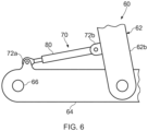
- Fig. 6 shows a landing gear assembly 60 according to an embodiment of the present invention.
- the landing gear 60 includes a main strut 62, having an upper portion (not shown) arranged to be coupled to the underside of an aircraft (not shown) and a lower portion 62b telescopically mounted with respect to the upper portion.
- a bogie beam 64 is pivotally coupled to the lower portion of the main strut 62b, the bogie beam 64 having axles 66 mounted on it for carrying one or more wheel assemblies (not shown).
- a landing gear assembly according to embodiments of the present invention may have any suitable number of axles and wheels per axle.
- the actuator 80 results in pivotal movement of the bogie beam 64 relative to the strut 62 and the actuator 80 can thus be used to "trim" the position of the bogie beam 64 for stowing.
- the coupling regions 72a, 72b could be reversed and may in other embodiments be coupled between any part of the bogie on the one hand and any part of the strut 62 on the other hand.
- the linkage 80 may include a multi bar linkage that is movable by an actuator so as to change the angular position of the bogie relative to the strut.
Landscapes
- Engineering & Computer Science (AREA)
- General Engineering & Computer Science (AREA)
- Mechanical Engineering (AREA)
- Physics & Mathematics (AREA)
- Fluid Mechanics (AREA)
- Aviation & Aerospace Engineering (AREA)
- Actuator (AREA)
Claims (11)
- Mittelpunkt suchender Aktuator (10), der aufweist:einen Außenzylinder (102), der eine erste axiale Fläche (102a) und eine zweite axiale Fläche (102b) aufweist, die durch eine oder mehrere erste Seitenwände (102c) verbunden sind, um ein Innenvolumen zu definieren, wobei die erste axiale Fläche (102a) ein erstes Durchgangsloch aufweist;einen Führungszylinder (14), der verschiebbar in dem Innenvolumen des Außenzylinders angeordnet ist, wobei der Führungszylinder eine dritte axiale Fläche (112a) und eine vierte axiale Fläche (112b) aufweist, die durch eine oder mehrere zweite Seitenwände (112c) verbunden sind, um eine Führungszylinderkammer (113) zu definieren, wobei die dritte axiale Fläche (112a) ein zweites Durchgangsloch aufweist,wobei der Führungszylinder das Innenvolumen des Außenzylinders in eine Gaskammer (109) und eine Arbeitsmedium-Primärkammer (104) teilt, wobei sich der Führungszylinder nur zwischen einem ersten und einem zweiten Endpunkt in dem Innenvolumen des Außenzylinders bewegen kann, um mindestens einen freien Bereich der Gaskammer zu hinterlassen, wobei der Außenzylinder eine Lüftungsöffnung (108) aufweist, die in Fluidverbindung mit dem freien Bereich der Gaskammer (109) steht;eine Kolbenstangenbaugruppe (120, 122), deren Kolben (122) verschiebbar in der Führungszylinderkammer angeordnet ist, und deren Stange (120) sich durch das zweite und das erste Durchgangsloch erstreckt, so dass ein freies Ende aus dem Außenzylinder herausragt; undeine oder mehrere erste dynamische Dichtungen (121), die so angeordnet sind, dass sie auf eine Außenfläche der Stange wirken, um zu verhindern, dass das Arbeitsmedium aus dem Außenzylinder austritt;eine oder mehrere zweite dynamische Dichtungen (12), die auf einer Innenfläche der einen oder mehreren ersten Seitenwände des Außenzylinders montiert und so angeordnet sind, dass sie auf eine Außenfläche der einen oder mehreren zweiten Seitenwände des Führungszylinders wirken, um zu verhindern, dass das Arbeitsmedium aus dem Außenzylinder austritt,wobei die eine oder die mehreren zweiten dynamischen Dichtungen so angeordnet sind, dass sie verhindern, dass das Arbeitsmedium in der Primärkammer zum freien Bereich der Gaskammer übertritt.
- Mittelpunkt suchender Aktuator nach Anspruch 1, wobei zumindest ein Teil der Außenfläche der einen oder mehreren Seitenwände des Führungszylinders, der im Gebrauch mit den zweiten dynamischen Dichtungen in Kontakt kommt, mit einer Beschichtung (C) versehen ist.
- Mittelpunkt suchender Aktuator nach Anspruch 2, wobei die Beschichtung eine Beschichtung durch Hochgeschwindigkeitsflammspritzen (HVOF) aufweist, die Metall, Metalllegierung, Keramik, Kunststoff oder Verbundwerkstoffe umfasst.
- Mittelpunkt suchender Aktuator nach Anspruch 2 oder Anspruch 3, wobei die Beschichtung Chrom oder Wolframkarbid umfasst.
- Mittelpunkt suchender Aktuator nach Anspruch 1, wobei die eine oder die mehreren ersten dynamischen Dichtungen an dem ersten Durchgangsloch oder angrenzend an dieses montiert und so angeordnet sind, dass sie auf eine Außenfläche der Stange wirken, um zu verhindern, dass das Arbeitsmedium in der Primärkammer durch das erste Durchgangsloch durchtritt.
- Mittelpunkt suchender Aktuator nach einem der vorstehenden Ansprüche, der mit Endanschlägen versehen ist, die so angeordnet sind, dass sie den ersten und den zweiten Endpunkt definieren, bis zu denen sich der Führungszylinder bewegen kann.
- Mittelpunkt suchender Aktuator nach einem der vorstehenden Ansprüche, wobei der Außenzylinder eine Länge aufweist und sich die eine oder die mehreren zweiten dynamischen Dichtungen näher an der Mitte des Außenzylinders befinden als an einem der beiden Enden desselben.
- Baugruppe, die einen Mittelpunkt suchenden Aktuator nach einem der vorstehenden Ansprüche aufweist, der angeordnet ist, dass er einen ersten Teil der Baugruppe vorspannt, um eine vorbestimmte Position relativ zum zweiten Teil einzunehmen, wobei die Baugruppe im Gebrauch so angeordnet ist, dass sie den Aktuator zwingt, den ersten Zustand anzunehmen, wenn dieser sich in einer ersten Lage befindet, und der eine zweite Lage aufweist, in welcher der Aktuator den ersten Teil der Baugruppe bewegt, um die vorbestimmte Position relativ zum zweiten Teil einzunehmen.
- Baugruppe nach Anspruch 8, die eine Flugzeugbaugruppe aufweist.
- Baugruppe nach Anspruch 9, die eine Flugzeugfahrwerksbaugruppe aufweist.
- Baugruppe nach Anspruch 10, wobei das erste Teil ein Drehgestell aufweist und das zweite Teil eine Hauptstrebe aufweist, wie z. B. ein Hauptfitting oder ein Gleitrohr eines Federbeins.
Priority Applications (5)
| Application Number | Priority Date | Filing Date | Title |
|---|---|---|---|
| EP16205169.2A EP3336378B1 (de) | 2016-12-19 | 2016-12-19 | Mittelpunkt suchendes stellglied |
| US15/834,800 US10794407B2 (en) | 2016-12-19 | 2017-12-07 | Centre seeking actuator |
| CN202511710203.4A CN121206031A (zh) | 2016-12-19 | 2017-12-11 | 寻找中心的致动器 |
| CN201711308460.0A CN108204384A (zh) | 2016-12-19 | 2017-12-11 | 寻找中心的致动器 |
| CA2989072A CA2989072C (en) | 2016-12-19 | 2017-12-13 | Centre seeking actuator |
Applications Claiming Priority (1)
| Application Number | Priority Date | Filing Date | Title |
|---|---|---|---|
| EP16205169.2A EP3336378B1 (de) | 2016-12-19 | 2016-12-19 | Mittelpunkt suchendes stellglied |
Publications (2)
| Publication Number | Publication Date |
|---|---|
| EP3336378A1 EP3336378A1 (de) | 2018-06-20 |
| EP3336378B1 true EP3336378B1 (de) | 2025-04-09 |
Family
ID=57681321
Family Applications (1)
| Application Number | Title | Priority Date | Filing Date |
|---|---|---|---|
| EP16205169.2A Active EP3336378B1 (de) | 2016-12-19 | 2016-12-19 | Mittelpunkt suchendes stellglied |
Country Status (4)
| Country | Link |
|---|---|
| US (1) | US10794407B2 (de) |
| EP (1) | EP3336378B1 (de) |
| CN (2) | CN121206031A (de) |
| CA (1) | CA2989072C (de) |
Families Citing this family (2)
| Publication number | Priority date | Publication date | Assignee | Title |
|---|---|---|---|---|
| WO2021059828A1 (ja) * | 2019-09-26 | 2021-04-01 | 日立Astemo株式会社 | シール状態検出装置およびシール状態検出方法 |
| CN111207130B (zh) * | 2020-02-04 | 2022-11-18 | 龙岩市山力工程液压有限公司 | 一种油缸 |
Family Cites Families (20)
| Publication number | Priority date | Publication date | Assignee | Title |
|---|---|---|---|---|
| GB679060A (en) * | 1950-05-11 | 1952-09-10 | Dowty Equipment Ltd | A fluid pressure controlled strut or link of variable length |
| US3631760A (en) * | 1969-12-05 | 1972-01-04 | Us Navy | Pneumatic torpedo launcher with hydraulic operated snubber |
| US7448310B2 (en) * | 2004-03-11 | 2008-11-11 | Atkisek Corporation | Innerscoping hydraulic system |
| GB2428650B (en) * | 2005-08-04 | 2011-01-12 | Messier Dowty Ltd | Landing gear |
| US20070272077A1 (en) * | 2006-05-24 | 2007-11-29 | Genie Industries, Inc. | Linear actuator assembly |
| DE102008035135A1 (de) * | 2008-07-28 | 2010-02-04 | Gustav Magenwirth Gmbh & Co. Kg | Kopplungsvorrichtung für ein Bremssystem eines lenkergeführten Kraftfahrzeugs |
| DE202009012284U1 (de) * | 2009-09-09 | 2010-01-07 | Schlutz, Heinz | Hydraulikzylinder mit Niro-Oberfläche |
| EP2558607B1 (de) * | 2010-03-19 | 2017-08-09 | Crucible Intellectual Property, LLC | Thermisch gespritztes pulver basiert auf eisen-chrom-molybdän und verfahren zu seinem herstellung. |
| GB2483472B (en) * | 2010-09-08 | 2012-08-15 | Messier Dowty Ltd | Aircraft landing gear |
| TW201219249A (en) * | 2010-11-05 | 2012-05-16 | de-san Chen | allowing return-oil fluid to pass a seal ring through simultaneous formation of two oil return passages while significantly reducing the pressure-release impedance in the hydraulic cylinder |
| FR2969096B1 (fr) * | 2010-12-17 | 2012-12-28 | Bosch Gmbh Robert | Procede de detection d'une erreur de montage d'un joint d'etancheite dans un maitre-cylindre |
| WO2012151709A1 (de) * | 2011-05-09 | 2012-11-15 | Mueller Peter A | Zylinderschotthalterung |
| EP2783932B1 (de) * | 2011-11-25 | 2016-06-15 | Honda Motor Co., Ltd. | Bremsvorrichtung |
| DE102012014321A1 (de) * | 2012-07-19 | 2014-01-23 | Lucas Automotive Gmbh | Hauptbremszylinder für eine Kraftfahrzeug-Bremsanlage mit profiliertem Druckkolben |
| EP2925900A1 (de) * | 2012-11-30 | 2015-10-07 | Eaton Corporation | Mehrschichtige beschichtungssysteme und verfahren |
| GB2510208B (en) * | 2013-04-25 | 2014-12-10 | Messier Dowty Ltd | Actuator |
| CN203685756U (zh) * | 2013-12-06 | 2014-07-02 | 天水锻压机床(集团)有限公司 | 大吨位水压机长行程油缸系统 |
| CN204152890U (zh) * | 2014-09-23 | 2015-02-11 | 广州科技职业技术学院 | 一种新型伸缩式柱塞液压缸 |
| CN105736512A (zh) * | 2016-04-26 | 2016-07-06 | 苏州普来可瑞机电技术有限公司 | 一种隐式串联节能气缸 |
| ES2900798T3 (es) * | 2017-11-16 | 2022-03-18 | Safran Landing Systems Uk Ltd | Actuador empujado hacia el centro |
-
2016
- 2016-12-19 EP EP16205169.2A patent/EP3336378B1/de active Active
-
2017
- 2017-12-07 US US15/834,800 patent/US10794407B2/en active Active
- 2017-12-11 CN CN202511710203.4A patent/CN121206031A/zh active Pending
- 2017-12-11 CN CN201711308460.0A patent/CN108204384A/zh active Pending
- 2017-12-13 CA CA2989072A patent/CA2989072C/en active Active
Also Published As
| Publication number | Publication date |
|---|---|
| CN108204384A (zh) | 2018-06-26 |
| CA2989072C (en) | 2023-06-27 |
| EP3336378A1 (de) | 2018-06-20 |
| US20180172035A1 (en) | 2018-06-21 |
| US10794407B2 (en) | 2020-10-06 |
| CN121206031A (zh) | 2025-12-26 |
| CA2989072A1 (en) | 2018-06-19 |
Similar Documents
| Publication | Publication Date | Title |
|---|---|---|
| US9879701B2 (en) | Actuator | |
| US6883650B2 (en) | Adjustable shock absorber | |
| EP2614001B1 (de) | Fahrwerk für ein flugzeug | |
| EP3746676B1 (de) | Schwingungsdämpfer für ein fahrzeug | |
| EP2945841B1 (de) | Geberarmatur für eine hydraulische scheibenbremse | |
| CN102203369A (zh) | 阻尼器 | |
| US11565798B2 (en) | Center biased actuator | |
| US6279854B1 (en) | Combined damper and truck positioner for landing gear | |
| EP3336378B1 (de) | Mittelpunkt suchendes stellglied | |
| CA3001991C (en) | Aircraft landing gear shock absorbing strut | |
| CN101509533B (zh) | 可调阻尼和软硬的摩托车前减震器 | |
| US20040145099A1 (en) | Mono-tube type hydraulic shock absorber | |
| US5325943A (en) | Variable orifice oil/gass damper for aircraft landing gear | |
| DE69813229T2 (de) | Hydraulische betätigungsvorrichtung mit metall-gegen-metall dichtungen | |
| DE69328866T2 (de) | Aufhängungssystem für fahrzeuge und steuerventil dafür | |
| US3203319A (en) | Internal lock for hydraulic actuator | |
| CA1239659A (en) | Fluid suspension spring and dampener for a vehicle suspension system | |
| EP2101066B1 (de) | Einrichtung zur Sicherung der Bewegungsreihenfolge von zumindest zwei fluidbetätigten Verdrängereinheiten | |
| US20200400164A1 (en) | Proportional Control Fluid Actuator | |
| WO2006098682A1 (en) | Device for adjusting the piston stroke at a pressure medium-activated piston-cylinder means |
Legal Events
| Date | Code | Title | Description |
|---|---|---|---|
| PUAI | Public reference made under article 153(3) epc to a published international application that has entered the european phase |
Free format text: ORIGINAL CODE: 0009012 |
|
| STAA | Information on the status of an ep patent application or granted ep patent |
Free format text: STATUS: THE APPLICATION HAS BEEN PUBLISHED |
|
| AK | Designated contracting states |
Kind code of ref document: A1 Designated state(s): AL AT BE BG CH CY CZ DE DK EE ES FI FR GB GR HR HU IE IS IT LI LT LU LV MC MK MT NL NO PL PT RO RS SE SI SK SM TR |
|
| AX | Request for extension of the european patent |
Extension state: BA ME |
|
| STAA | Information on the status of an ep patent application or granted ep patent |
Free format text: STATUS: REQUEST FOR EXAMINATION WAS MADE |
|
| 17P | Request for examination filed |
Effective date: 20181113 |
|
| RBV | Designated contracting states (corrected) |
Designated state(s): AL AT BE BG CH CY CZ DE DK EE ES FI FR GB GR HR HU IE IS IT LI LT LU LV MC MK MT NL NO PL PT RO RS SE SI SK SM TR |
|
| STAA | Information on the status of an ep patent application or granted ep patent |
Free format text: STATUS: EXAMINATION IS IN PROGRESS |
|
| 17Q | First examination report despatched |
Effective date: 20211004 |
|
| REG | Reference to a national code |
Ref country code: DE Ref legal event code: R079 Free format text: PREVIOUS MAIN CLASS: F16F0009360000 Ipc: B64C0025580000 Ref country code: DE Ref legal event code: R079 Ref document number: 602016091821 Country of ref document: DE Free format text: PREVIOUS MAIN CLASS: F16F0009360000 Ipc: B64C0025580000 |
|
| RIC1 | Information provided on ipc code assigned before grant |
Ipc: B64C 25/22 20060101ALN20241021BHEP Ipc: B64C 25/60 20060101ALN20241021BHEP Ipc: B64C 25/58 20060101AFI20241021BHEP |
|
| GRAP | Despatch of communication of intention to grant a patent |
Free format text: ORIGINAL CODE: EPIDOSNIGR1 |
|
| STAA | Information on the status of an ep patent application or granted ep patent |
Free format text: STATUS: GRANT OF PATENT IS INTENDED |
|
| RIC1 | Information provided on ipc code assigned before grant |
Ipc: B64C 25/22 20060101ALN20241206BHEP Ipc: B64C 25/60 20060101ALN20241206BHEP Ipc: B64C 25/58 20060101AFI20241206BHEP |
|
| INTG | Intention to grant announced |
Effective date: 20241219 |
|
| GRAS | Grant fee paid |
Free format text: ORIGINAL CODE: EPIDOSNIGR3 |
|
| GRAA | (expected) grant |
Free format text: ORIGINAL CODE: 0009210 |
|
| STAA | Information on the status of an ep patent application or granted ep patent |
Free format text: STATUS: THE PATENT HAS BEEN GRANTED |
|
| AK | Designated contracting states |
Kind code of ref document: B1 Designated state(s): AL AT BE BG CH CY CZ DE DK EE ES FI FR GB GR HR HU IE IS IT LI LT LU LV MC MK MT NL NO PL PT RO RS SE SI SK SM TR |
|
| REG | Reference to a national code |
Ref country code: GB Ref legal event code: FG4D |
|
| REG | Reference to a national code |
Ref country code: CH Ref legal event code: EP |
|
| REG | Reference to a national code |
Ref country code: DE Ref legal event code: R096 Ref document number: 602016091821 Country of ref document: DE |
|
| REG | Reference to a national code |
Ref country code: IE Ref legal event code: FG4D |
|
| REG | Reference to a national code |
Ref country code: NL Ref legal event code: MP Effective date: 20250409 |
|
| PG25 | Lapsed in a contracting state [announced via postgrant information from national office to epo] |
Ref country code: NL Free format text: LAPSE BECAUSE OF FAILURE TO SUBMIT A TRANSLATION OF THE DESCRIPTION OR TO PAY THE FEE WITHIN THE PRESCRIBED TIME-LIMIT Effective date: 20250409 |
|
| REG | Reference to a national code |
Ref country code: AT Ref legal event code: MK05 Ref document number: 1783339 Country of ref document: AT Kind code of ref document: T Effective date: 20250409 |
|
| PG25 | Lapsed in a contracting state [announced via postgrant information from national office to epo] |
Ref country code: FI Free format text: LAPSE BECAUSE OF FAILURE TO SUBMIT A TRANSLATION OF THE DESCRIPTION OR TO PAY THE FEE WITHIN THE PRESCRIBED TIME-LIMIT Effective date: 20250409 Ref country code: ES Free format text: LAPSE BECAUSE OF FAILURE TO SUBMIT A TRANSLATION OF THE DESCRIPTION OR TO PAY THE FEE WITHIN THE PRESCRIBED TIME-LIMIT Effective date: 20250409 Ref country code: PT Free format text: LAPSE BECAUSE OF FAILURE TO SUBMIT A TRANSLATION OF THE DESCRIPTION OR TO PAY THE FEE WITHIN THE PRESCRIBED TIME-LIMIT Effective date: 20250811 |
|
| REG | Reference to a national code |
Ref country code: LT Ref legal event code: MG9D |
|
| PG25 | Lapsed in a contracting state [announced via postgrant information from national office to epo] |
Ref country code: NO Free format text: LAPSE BECAUSE OF FAILURE TO SUBMIT A TRANSLATION OF THE DESCRIPTION OR TO PAY THE FEE WITHIN THE PRESCRIBED TIME-LIMIT Effective date: 20250709 Ref country code: GR Free format text: LAPSE BECAUSE OF FAILURE TO SUBMIT A TRANSLATION OF THE DESCRIPTION OR TO PAY THE FEE WITHIN THE PRESCRIBED TIME-LIMIT Effective date: 20250710 |
|
| PG25 | Lapsed in a contracting state [announced via postgrant information from national office to epo] |
Ref country code: PL Free format text: LAPSE BECAUSE OF FAILURE TO SUBMIT A TRANSLATION OF THE DESCRIPTION OR TO PAY THE FEE WITHIN THE PRESCRIBED TIME-LIMIT Effective date: 20250409 |
|
| PG25 | Lapsed in a contracting state [announced via postgrant information from national office to epo] |
Ref country code: BG Free format text: LAPSE BECAUSE OF FAILURE TO SUBMIT A TRANSLATION OF THE DESCRIPTION OR TO PAY THE FEE WITHIN THE PRESCRIBED TIME-LIMIT Effective date: 20250409 |
|
| PG25 | Lapsed in a contracting state [announced via postgrant information from national office to epo] |
Ref country code: HR Free format text: LAPSE BECAUSE OF FAILURE TO SUBMIT A TRANSLATION OF THE DESCRIPTION OR TO PAY THE FEE WITHIN THE PRESCRIBED TIME-LIMIT Effective date: 20250409 |
|
| PG25 | Lapsed in a contracting state [announced via postgrant information from national office to epo] |
Ref country code: AT Free format text: LAPSE BECAUSE OF FAILURE TO SUBMIT A TRANSLATION OF THE DESCRIPTION OR TO PAY THE FEE WITHIN THE PRESCRIBED TIME-LIMIT Effective date: 20250409 |
|
| PG25 | Lapsed in a contracting state [announced via postgrant information from national office to epo] |
Ref country code: RS Free format text: LAPSE BECAUSE OF FAILURE TO SUBMIT A TRANSLATION OF THE DESCRIPTION OR TO PAY THE FEE WITHIN THE PRESCRIBED TIME-LIMIT Effective date: 20250709 |
|
| PG25 | Lapsed in a contracting state [announced via postgrant information from national office to epo] |
Ref country code: IS Free format text: LAPSE BECAUSE OF FAILURE TO SUBMIT A TRANSLATION OF THE DESCRIPTION OR TO PAY THE FEE WITHIN THE PRESCRIBED TIME-LIMIT Effective date: 20250809 |
|
| PG25 | Lapsed in a contracting state [announced via postgrant information from national office to epo] |
Ref country code: LV Free format text: LAPSE BECAUSE OF FAILURE TO SUBMIT A TRANSLATION OF THE DESCRIPTION OR TO PAY THE FEE WITHIN THE PRESCRIBED TIME-LIMIT Effective date: 20250409 |
|
| PGFP | Annual fee paid to national office [announced via postgrant information from national office to epo] |
Ref country code: GB Payment date: 20251229 Year of fee payment: 10 |
|
| PG25 | Lapsed in a contracting state [announced via postgrant information from national office to epo] |
Ref country code: DK Free format text: LAPSE BECAUSE OF FAILURE TO SUBMIT A TRANSLATION OF THE DESCRIPTION OR TO PAY THE FEE WITHIN THE PRESCRIBED TIME-LIMIT Effective date: 20250409 Ref country code: SM Free format text: LAPSE BECAUSE OF FAILURE TO SUBMIT A TRANSLATION OF THE DESCRIPTION OR TO PAY THE FEE WITHIN THE PRESCRIBED TIME-LIMIT Effective date: 20250409 |
|
| PGFP | Annual fee paid to national office [announced via postgrant information from national office to epo] |
Ref country code: FR Payment date: 20251222 Year of fee payment: 10 |
|
| PG25 | Lapsed in a contracting state [announced via postgrant information from national office to epo] |
Ref country code: CZ Free format text: LAPSE BECAUSE OF FAILURE TO SUBMIT A TRANSLATION OF THE DESCRIPTION OR TO PAY THE FEE WITHIN THE PRESCRIBED TIME-LIMIT Effective date: 20250409 |
|
| PG25 | Lapsed in a contracting state [announced via postgrant information from national office to epo] |
Ref country code: EE Free format text: LAPSE BECAUSE OF FAILURE TO SUBMIT A TRANSLATION OF THE DESCRIPTION OR TO PAY THE FEE WITHIN THE PRESCRIBED TIME-LIMIT Effective date: 20250409 |
|
| PG25 | Lapsed in a contracting state [announced via postgrant information from national office to epo] |
Ref country code: SK Free format text: LAPSE BECAUSE OF FAILURE TO SUBMIT A TRANSLATION OF THE DESCRIPTION OR TO PAY THE FEE WITHIN THE PRESCRIBED TIME-LIMIT Effective date: 20250409 Ref country code: RO Free format text: LAPSE BECAUSE OF FAILURE TO SUBMIT A TRANSLATION OF THE DESCRIPTION OR TO PAY THE FEE WITHIN THE PRESCRIBED TIME-LIMIT Effective date: 20250409 |
|
| PG25 | Lapsed in a contracting state [announced via postgrant information from national office to epo] |
Ref country code: IT Free format text: LAPSE BECAUSE OF FAILURE TO SUBMIT A TRANSLATION OF THE DESCRIPTION OR TO PAY THE FEE WITHIN THE PRESCRIBED TIME-LIMIT Effective date: 20250409 |
|
| PLBE | No opposition filed within time limit |
Free format text: ORIGINAL CODE: 0009261 |
|
| STAA | Information on the status of an ep patent application or granted ep patent |
Free format text: STATUS: NO OPPOSITION FILED WITHIN TIME LIMIT |