EP3336041B1 - System to compensate the motion of a load attached to a mobile installation with a main cylinder and a secondary cylinder - Google Patents
System to compensate the motion of a load attached to a mobile installation with a main cylinder and a secondary cylinder Download PDFInfo
- Publication number
- EP3336041B1 EP3336041B1 EP17306643.2A EP17306643A EP3336041B1 EP 3336041 B1 EP3336041 B1 EP 3336041B1 EP 17306643 A EP17306643 A EP 17306643A EP 3336041 B1 EP3336041 B1 EP 3336041B1
- Authority
- EP
- European Patent Office
- Prior art keywords
- cylinder
- cylinders
- articulated arm
- main
- compensation system
- Prior art date
- Legal status (The legal status is an assumption and is not a legal conclusion. Google has not performed a legal analysis and makes no representation as to the accuracy of the status listed.)
- Active
Links
- 238000009434 installation Methods 0.000 title description 53
- 238000006073 displacement reaction Methods 0.000 claims description 3
- 238000005553 drilling Methods 0.000 description 9
- 230000006835 compression Effects 0.000 description 4
- 238000007906 compression Methods 0.000 description 4
- 238000005452 bending Methods 0.000 description 3
- 230000000295 complement effect Effects 0.000 description 3
- 238000007792 addition Methods 0.000 description 2
- 239000004459 forage Substances 0.000 description 2
- 238000012856 packing Methods 0.000 description 2
- 230000000712 assembly Effects 0.000 description 1
- 238000000429 assembly Methods 0.000 description 1
- 238000013016 damping Methods 0.000 description 1
- 230000008021 deposition Effects 0.000 description 1
- 230000000694 effects Effects 0.000 description 1
- 230000009916 joint effect Effects 0.000 description 1
- 239000007788 liquid Substances 0.000 description 1
- 230000003534 oscillatory effect Effects 0.000 description 1
- 230000001151 other effect Effects 0.000 description 1
- 238000011084 recovery Methods 0.000 description 1
Images


Classifications
-
- E—FIXED CONSTRUCTIONS
- E21—EARTH DRILLING; MINING
- E21B—EARTH DRILLING, e.g. DEEP DRILLING; OBTAINING OIL, GAS, WATER, SOLUBLE OR MELTABLE MATERIALS OR A SLURRY OF MINERALS FROM WELLS
- E21B19/00—Handling rods, casings, tubes or the like outside the borehole, e.g. in the derrick; Apparatus for feeding the rods or cables
- E21B19/002—Handling rods, casings, tubes or the like outside the borehole, e.g. in the derrick; Apparatus for feeding the rods or cables specially adapted for underwater drilling
- E21B19/004—Handling rods, casings, tubes or the like outside the borehole, e.g. in the derrick; Apparatus for feeding the rods or cables specially adapted for underwater drilling supporting a riser from a drilling or production platform
- E21B19/006—Handling rods, casings, tubes or the like outside the borehole, e.g. in the derrick; Apparatus for feeding the rods or cables specially adapted for underwater drilling supporting a riser from a drilling or production platform including heave compensators
-
- B—PERFORMING OPERATIONS; TRANSPORTING
- B66—HOISTING; LIFTING; HAULING
- B66C—CRANES; LOAD-ENGAGING ELEMENTS OR DEVICES FOR CRANES, CAPSTANS, WINCHES, OR TACKLES
- B66C13/00—Other constructional features or details
- B66C13/02—Devices for facilitating retrieval of floating objects, e.g. for recovering crafts from water
-
- B—PERFORMING OPERATIONS; TRANSPORTING
- B66—HOISTING; LIFTING; HAULING
- B66C—CRANES; LOAD-ENGAGING ELEMENTS OR DEVICES FOR CRANES, CAPSTANS, WINCHES, OR TACKLES
- B66C23/00—Cranes comprising essentially a beam, boom, or triangular structure acting as a cantilever and mounted for translatory of swinging movements in vertical or horizontal planes or a combination of such movements, e.g. jib-cranes, derricks, tower cranes
- B66C23/18—Cranes comprising essentially a beam, boom, or triangular structure acting as a cantilever and mounted for translatory of swinging movements in vertical or horizontal planes or a combination of such movements, e.g. jib-cranes, derricks, tower cranes specially adapted for use in particular purposes
- B66C23/36—Cranes comprising essentially a beam, boom, or triangular structure acting as a cantilever and mounted for translatory of swinging movements in vertical or horizontal planes or a combination of such movements, e.g. jib-cranes, derricks, tower cranes specially adapted for use in particular purposes mounted on road or rail vehicles; Manually-movable jib-cranes for use in workshops; Floating cranes
- B66C23/52—Floating cranes
-
- E—FIXED CONSTRUCTIONS
- E21—EARTH DRILLING; MINING
- E21B—EARTH DRILLING, e.g. DEEP DRILLING; OBTAINING OIL, GAS, WATER, SOLUBLE OR MELTABLE MATERIALS OR A SLURRY OF MINERALS FROM WELLS
- E21B15/00—Supports for the drilling machine, e.g. derricks or masts
- E21B15/02—Supports for the drilling machine, e.g. derricks or masts specially adapted for underwater drilling
-
- F—MECHANICAL ENGINEERING; LIGHTING; HEATING; WEAPONS; BLASTING
- F15—FLUID-PRESSURE ACTUATORS; HYDRAULICS OR PNEUMATICS IN GENERAL
- F15B—SYSTEMS ACTING BY MEANS OF FLUIDS IN GENERAL; FLUID-PRESSURE ACTUATORS, e.g. SERVOMOTORS; DETAILS OF FLUID-PRESSURE SYSTEMS, NOT OTHERWISE PROVIDED FOR
- F15B1/00—Installations or systems with accumulators; Supply reservoir or sump assemblies
- F15B1/02—Installations or systems with accumulators
-
- F—MECHANICAL ENGINEERING; LIGHTING; HEATING; WEAPONS; BLASTING
- F15—FLUID-PRESSURE ACTUATORS; HYDRAULICS OR PNEUMATICS IN GENERAL
- F15B—SYSTEMS ACTING BY MEANS OF FLUIDS IN GENERAL; FLUID-PRESSURE ACTUATORS, e.g. SERVOMOTORS; DETAILS OF FLUID-PRESSURE SYSTEMS, NOT OTHERWISE PROVIDED FOR
- F15B21/00—Common features of fluid actuator systems; Fluid-pressure actuator systems or details thereof, not covered by any other group of this subclass
Definitions
- the present invention relates to the field of motion compensation of a mobile element suspended from a mobile installation.
- the invention relates more particularly to the compensation of a heave movement of a floating (offshore) offshore installation, supporting either a drill string terminated by a drilling tool (drill string), or a riser connected in a manner rigid to an equipment attached to the bottom.
- a floating installation must also be compensated for the vertical heave during installation and especially during assembly at the bottom of various equipment, such as for example an underwater wellhead.
- the load bearing systems are made by means of a cable winch and a set of fixed and movable pulleys.
- the load is likely to be operated more or less regularly, for example gradually increased (case of successive additions of drill pipe), then placed partially on the bottom (drilling) , and finally resumed and rested as necessary, as drilling progresses.
- the swell causes, among other effects, the heave, that is to say an oscillatory movement of vertical translation, floating devices.
- these support equipment in contact with the bottom such as a drill string, it is necessary to compensate for heave to maintain, within acceptable limits, the contact force of the tool with the bottom of the hole,
- a compensation system comprises at least one main cylinder, one end of which is fixedly connected (without relative movement) to the upper end of the load (fixed muffle) and the other end is fixedly connected (without movement relative) to the mobile installation.
- Each main cylinder accompanies the heave movement and is therefore deployed vertically or in a direction very close to the vertical.
- the compensation system comprises at least one articulated arm connecting the mobile installation to the fixed mittle.
- Each articulated arm is formed of rigid elements hinged together, in this case by pivotal connections between the rigid elements. For the same reason as for the main cylinders, these arms are movable in substantially vertical planes, and the axes of their joints are horizontal.
- the document FR 2575452 ( US 5520369 ) discloses such a system comprising two mittens, at least one compensation cylinder connected to accumulators, a cable, and two articulated arms which comprise pulleys and connecting rods for compensating a movement for an element hooked on a mobile installation.
- This system makes it possible to reduce the volume of the accumulators by a suitable geometry of the articulated arms and to reduce part of the error.
- the volume of the accumulators remains large (about 16m 3 for a conventional architecture), and compensation errors remain significant; the force on the load remains little constant.
- the patent application WO 2004/001193 describes a refinement of the system described in the document FR 2575452 ( US 5520369 ).
- the improvement consists in using, in addition to the main vertical cylinders, secondary cylinders, which connect the floating installation and some rods articulated arms.
- the secondary cylinders solicit these rods in bending in addition to traction or compression, which forces an oversize of these rods.
- this patent application specifies that the main cylinders and the secondary cylinders are connected to the same reserve of pressurized gas, which makes the system inefficient and not easily adjustable.
- the present invention relates to a motion compensation system for a load attached to a mobile installation.
- the compensation system comprises two mittens, at least one articulated arm, a cable, at least one main cylinder and at least one secondary cylinder.
- the secondary cylinder is mounted in tilting (rotation about a substantially horizontal axis) on the mobile installation, and on the articulation of the articulated arm.
- the secondary cylinder makes it possible to increase the precision of the compensation of the movement, to make the system adjustable, and its action at the articulation of the articulated arm makes it possible to avoid the bending forces in the connecting rods of the articulated arm, and so to lighten them.
- the invention relates to a motion compensation system for a load attached to a mobile installation, comprising a fixed muffle, a movable muffle for hanging said load, at least one articulated arm for connecting said fixed mitt to said mobile installation, each articulated arm. comprising at least one pulley, a cable passing through said pulleys of each articulated arm and said first and second muffles, and at least a first main cylinder fixed on said movable installation and said fixed muffle.
- Said compensation system comprises at least one secondary jack rotatably mounted on said mobile installation and on the articulation of said articulated arm.
- said main cylinder is a hydropneumatic cylinder connected to an oleopneumatic accumulator.
- said secondary cylinder is a pneumatic cylinder connected to a pneumatic accumulator.
- said articulated arm comprises at least two links articulated with respect to each other, a pulley being arranged at the articulation of said connecting rods on which is rotatably mounted said secondary cylinder.
- each end of said connecting rods comprises a pulley for the passage of said cable.
- said compensation system comprises at least two articulated arms arranged symmetrically with respect to the axis formed by said first and second muffles.
- said compensation system comprises at least two secondary cylinders arranged symmetrically with respect to the axis of said main cylinder, so that the components of the actions of said secondary cylinders orthogonal to the direction of movement of said fixed muffle cancel out for any position of said fixed mittle.
- said motion compensation system comprises two main cylinders.
- said compensation system comprises two secondary cylinders for each articulated arm.
- the invention relates to a use of a motion compensation system according to one of the preceding features, for heave compensation for the support of drilling tools and / or for the deposition of charge at sea.
- the present invention relates to a motion compensation system (heave compensator) for an element (also called a load) hooked (or suspended) to a mobile installation (for example a ship, a floating platform, etc.).
- the load is likely to be maneuvered more or less regularly, for example increased gradually (case of successive additions of a drill string), then placed partially on the bottom (drilling), and finally resumed and rested as necessary as the drilling progresses.
- These maneuvers are most often performed by means of a cable winch and a set of fixed and mobile pulleys (hauling) to reduce the effort required of the winch, at the cost of greater cable travel.
- the hauling consists of a first muffle, called muffle fixed (in English “crown block”) and a second muffle, said muffle moving (in English “traveling block”). It is recalled that a muffle is a mechanical device for lifting a load by several strands of cable.
- the articulated arms make it possible to keep the length of the cable substantially constant during the movement of the first muffle with respect to the mobile installation.
- the increase in the number of articulated arms allows in particular to increase the maximum allowable load by the compensation system.
- the articulated arm or arms described above are equipped with at least one pulley disposed at one end and / or articulation of the arms so as to guide the strands of the operating cable coming out of the fixed muffle parallel to the rigid elements making up said arms.
- the purpose of such a path being to keep constant the length of the operating cable strands between the fixed block and their attachments to the mobile installation, winch and anchor dead strand (as described in the patent application FR2575452 ( US 5520369 )), in order to make the tension of said cable independent of the relative positions of the fixed block and the mobile installation.
- the articulated arm may comprise three articulated rods.
- the motion compensation system further comprises at least one secondary cylinder.
- the secondary cylinder connects the mobile device and a joint of the articulated arm.
- the secondary cylinder is tilt-mounted (mounted in rotation) on the movable installation, and on the articulation of the articulated arm.
- the secondary cylinder can pivot relative to the mobile installation about a substantially horizontal axis, and the secondary cylinder can pivot about the axis of articulation of the articulated arm about a substantially horizontal axis .
- the joint action of the main cylinder and the secondary cylinder allows the compensation of the movement of the mobile installation (heave).
- the principle of this architecture is to exert a complementary force on the upper end of the load (fixed muffle) using the secondary cylinder.
- the secondary cylinder optimizes the motion compensation compared to the use of a main cylinder alone, and allows a smaller dimensioning of the main cylinder and its energy source.
- the connection of the secondary cylinder to the articulation of the articulated arm avoids the bending stresses in the connecting rods of the articulated arm.
- the movement of the mobile installation (eg heave) is compensated by moving the fixed muffle relative to the mobile installation.
- the load suspended from this fixed muffle is stationary relative to a fixed reference (for example the bottom of the sea).
- the displacement of the fixed muffle relative to the mobile installation is controlled by the jacks.
- the fixed muffle can be mounted on a support element (for example a gantry), the main cylinder can then be arranged between the mobile installation and the gantry.
- a support element for example a gantry
- the articulated arms make it possible to keep the length of the cable substantially constant during the movement of the fixed muffle with respect to the mobile installation.
- the compensation system may comprise at least two secondary cylinders arranged symmetrically with respect to the axis of the main jack, so that that the components of the actions of the secondary cylinders orthogonal (that is to say substantially horizontal) to the direction of the race of the first muffle, are canceled for any position of the first muffle. In this way, the resultant actions of the cylinders on the first muffle is substantially vertical.
- each articulated arm may comprise two connecting rods and a pulley.
- a first end of a first rod can then be hinged to the mobile installation.
- a second end of a first link may be articulated relative to a first end of the second link.
- a second end of the second connecting rod may be articulated relative to the first muffle, or relative to the gantry supporting the first muffle.
- a pulley can be installed at the joint between the two connecting rods.
- the articulated arm may comprise three articulated rods.
- each articulated arm composed of two connecting rods is associated with a secondary cylinder pulling, in the vertical plane defined by the two connecting rods, between the articulation of the connecting rods and the mobile installation.
- the force of the secondary cylinder produces a compression of the connecting rod attached to the fixed muffle.
- the vertical component of this compression is added to or subtracted from the vertical force of the main cylinder or cylinders, depending on the inclination of the connecting rod.
- the articulated arms being arranged symmetrically with respect to the vertical axis of the displacement of the load, the horizontal components of the compression of the rods attached to the fixed mittle cancel each other out.
- the nominal load of the compensation system corresponds to the force deployed by the main cylinders halfway.
- the extreme deviations, positive and negative, of the force deployed by the main cylinders relative to the nominal load correspond to the beginning and end of stroke of these same cylinders.
- the vertical forces to be provided by the sets of articulated arms and secondary cylinders must therefore vary between 0 and 100 tons, upwards or downwards depending on the position above or below the half-stroke, where the connecting rods attached to the fixed mitt are substantially horizontal and where the compensating force is zero.
- the compensation system may comprise two secondary cylinders for each articulated arm.
- the two secondary cylinders can be arranged parallel between the mobile installation and the articulation of the articulated arm.
- the two secondary cylinders are rotatably mounted on the articulation on either side of the pulley and connecting rods. This configuration allows balancing efforts on the axis of the joint. In addition, this configuration allows the use of secondary cylinders of reduced size.
- the articulated arm-auxiliary jack assemblies can be arranged symmetrically with respect to the vertical axis of the load, the horizontal components of the complementary forces are balanced and canceled.
- the resultant of the vertical components is added or subtracted, according to the inclination of the connecting rods, to the force of the main cylinders.
- the main jack may be a hydropneumatic jack connected to an oleopneumatic accumulator.
- accumulator refers to a supply of gas under pressure, for example air, in connection with an intermediate cylinder of the oleopneumatic type, which separates the gas from the gas reserve, and the oil from the hydraulic cylinder.
- the pressurized gas supply can be in the form of gas cylinders.
- the main cylinders can be connected to a reserve of compressed gas providing the necessary elasticity.
- An incompressible liquid is arranged between the cylinders and the gas reserve, to ensure the safety of the system by the rapid closure of a valve so as to prevent the expansion of the gas too fast in the event of a sudden loss of charge.
- this oleopneumatic damping system can be identical to that described in the document FR 2575452 ( US 5520369 ), with an oleopneumatic accumulator of reduced size.
- an oleopneumatic accumulator of reduced size.
- the secondary cylinder may be a pneumatic cylinder connected to a pneumatic accumulator, which may be in the form of gas cylinders.
- the pneumatic accumulator is distinct from the oleopneumatic accumulator provided for the main cylinder: the compensation system then comprises two independent accumulators.
- each type of cylinder main or secondary
- has its own source of energy which improves the accuracy of the compensation.
- the volume of the pneumatic accumulator of the secondary cylinders is much smaller than the volume of the oleopneumatic accumulator of the main cylinders.
- the best compensation ⁇ 2.54 tonnes, or 0.54% of the load
- a main storage volume of 6 m 3 and a secondary storage volume of 0.4 m 3 , with maximum pressures of 210 and 167 bar respectively.
- the secondary cylinders can be actuated cylinders, hydraulic pneumatic or electric.
- the secondary cylinders can be actuated cylinders, hydraulic pneumatic or electric.
- the compensation system may comprise two main cylinders arranged symmetrically between the mobile installation and the fixed muffle (or the gantry supporting the fixed muffle).
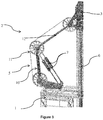
- the figure 1 illustrates, schematically and without limitation, a motion compensator according to one embodiment of the invention.
- the load is not shown.
- a load is suspended on a movable block 4, connected by a cable 5 to a fixed block 3.
- the fixed block 3 is mounted on a gantry, which is connected to the mobile installation 1 by two articulated arms 2.
- Each articulated arm comprises a lower link 10 articulated (that is to say in rotation about a substantially horizontal axis) relative to the mobile installation 1, and an upper rod 12 articulated (that is to say in rotation around a horizontal axis) on the one hand relative to the fixed block 3, and secondly with respect to the lower link 10.
- the articulation between the upper link 12 and the lower link 10 further comprises a pulley 11.
- the compensation system comprises a main cylinder 6 and two secondary cylinders 7.
- the main cylinder 6 is a hydraulic cylinder, one end of which is fixed to the mobile installation 1, and whose other end is fixed to the frame, on which The main cylinder 6 is fed by an oleopneumatic accumulator 8.
- the compensation system further comprises two secondary cylinders distributed symmetrically on either side of the load.
- the secondary cylinders 7 are arranged between the mobile installation 1 and a joint of the articulated arm 2, at the level of the pulley 11.
- the two secondary cylinders 7 are pneumatic cylinders fed by a pneumatic accumulator 9.
- FIGS. 2a to 2d illustrate schematically and without limitation the operation of the compensation system according to the invention for four different positions.
- the cylinders are shown schematically by springs.
- the mobile installation, the mittens, the pulleys, and the cable are not represented.
- the figures illustrate two articulated arms with a lower connecting rod 10 and an upper connecting rod 12, which connect the mobile installation to the first muffle, as well as the main jack 6 and two secondary cylinders 7 connecting the mobile installation and the articulation of the articulated arm. .
- the forces exerted on the fixed mitt are represented.
- Fp corresponds to the force exerted by the main cylinder on the first muffle
- Fs represents the forces exerted by the secondary cylinders on the fixed muffle via the connecting rod
- P is the resultant of these three efforts.
- the figure 2a illustrates the lowest position of the first muffle.
- the main cylinder 6 is compressed and exerts a maximum force Fp on the first muffle.
- the upper link 12 is inclined downwards, therefore, the forces Fs exerted by the secondary cylinders 7 on the fixed muffle are downward forces.
- the vertical component of the forces Fs of the secondary cylinders thus takes refuge in the force Fp of the main cylinder.
- the figure 2b illustrates an intermediate position of the first muffle, wherein the upper links 12 are substantially horizontal, that is to say substantially orthogonal to the movement of the first muffle.
- the forces Fs of the secondary cylinders on the fixed muffle therefore do not comprise a vertical component (the forces Fs cancel each other out).
- the resultant forces on the fixed mittle therefore corresponds only to the force Fp exerted by the main cylinder.
- the Figure 2c illustrates an intermediate position of the first muffle, for which the fixed muffle is in a higher position relative to the figure 2b .
- the main cylinder 6 is weakly compressed and exerts a low force Fb on the first muffle.
- the upper link is inclined upwards, therefore, the forces Fs exerted by the secondary cylinders 7 on the fixed muffle are efforts directed upwards.
- the vertical component of the forces Fs of the secondary cylinders is therefore added to the force Fp of the main cylinder.
- the figure 2d illustrates the highest position of the first mittens.
- the main cylinder 6 is weakly compressed and exerts a minimal force Fb on the first muffle.
- the upper link is strongly inclined upwards, therefore, the forces Fs exerted by the secondary cylinders 7 on the fixed muffle are efforts directed upwards.
- the vertical component of the forces Fs of the secondary cylinders is therefore added to the force Fp of the main cylinder.
- the figure 3 illustrates, schematically and in a nonlimiting manner, a motion compensator according to an alternative embodiment of the invention.
- This figure is a partial view illustrating a single articulated arm 2.
- a load (not shown) is suspended on a movable muffle (not shown), connected by a cable 5 to a fixed muffle 3.
- the fixed muffle 3 is mounted on a gantry , which is connected to the mobile installation 1 by two articulated arms 2.
- the articulated arm comprises a lower link 10 articulated (that is to say in rotation about a horizontal axis) relative to the mobile installation 1 and an upper link 12 articulated (that is to say in rotation about a horizontal axis) on the one hand relative to the fixed mittle 3, and secondly with respect to the lower link 10.
- the L articulation between the upper connecting rod 12 and the connecting rod lower 10 further comprises a pulley 11. Pulleys are also provided at the ends of the rods 10 and 12.
- the cable 5 passes through all the pulleys of the articulated arms and the two mittens.
- the compensation system comprises a main cylinder 6 and secondary cylinders 7.
- the main cylinder 6 is a hydraulic cylinder, one end of which is fixed to the mobile installation 1, and the other end of which is fixed to the gantry, on which the fixed muffle 3 is mounted.
- the main cylinder 6 is fed by an oleopneumatic accumulator (not shown).
- the compensation system further comprises two secondary cylinders arranged between the mobile installation 1 and the articulation of the articulated arm 2, at the pulley 11.
- the secondary cylinders 7 are positioned on either side pulley 11 for balancing efforts.
- the two secondary cylinders 7 are pneumatic cylinders powered by a pneumatic accumulator (not shown).
- the compensation system according to the invention can be used in particular to compensate for the heave of an offshore installation (ship, platform, etc.) during a drilling operation at sea, during the installation of a riser (in English). "Riser"), for a tool for installing a sea pressure shutter block, or the recovery of the bottom to restart drilling.
- the mobile installation is a floating installation, in particular a ship, and the hung element is a drill string or a riser or a tool for installing equipment at sea.
- a heave compensation system according to the invention is tested in order to show the interest of the compensation system.
- the example used is a compensation system comprising two hydropneumatic main cylinders connected to an oleopneumatic accumulator, two articulated arms, and four pneumatic secondary cylinders (two per articulated arm) connected to a pneumatic accumulator.
- the figure 4 illustrates a setting of such a compensation system (only part of the compensation system is shown).
- the compensation system comprises a hydropneumatic jack 6 fed by a hydropneumatic accumulator 8 of volume V1 and pressure P1.
- the compensation system comprises an articulated arm with a lower link 10 and an upper link 12.
- the compensation system further comprises a pneumatic secondary jack 7 and powered by a pneumatic accumulator 9 of volume V2 and pressure P2.
- the figure 4 illustrates the various dimensions of this system noted in particular, s, e, x, y, g, l, m.
- Table 1 specifies the dimensioning of the compensation system, the dimensions s, e, x and y can be dimensioned to have a substantially constant length of cable, regardless of the dimensioning of the main and secondary cylinders: Table 1 - Size of the compensation system Settings Values Charge 454 t Fixed muffle race s 7.6 m P1 209 bars P2 166 bars V1 6 m 3 V2 0.4 m 3 The 6.5 m M 4.85 m
- the maximum absolute distance of the resulting lift POR from the hanging weight CON is less than 4.54 tonnes, or 1% of the load.
- the device is therefore efficient when compared to the prior art, for which the best results are rather of the order of 2% or more.
- the main interest of the device lies in reducing the total volume of air at high pressure required.
Description
La présente invention concerne le domaine de la compensation de mouvement d'un élément mobile suspendu à une installation mobile. L'invention concerne plus particulièrement la compensation d'un mouvement de pilonnement d'une installation offshore (en mer) flottante, supportant soit un train de tiges terminé par un outil de forage (garniture de forage), soit une colonne montante reliée de manière rigide à un équipement fixé au fond. Une telle installation flottante doit également être compensée pour le pilonnement vertical lors de la pose et surtout lors de l'assemblage au fond de divers équipements, comme par exemple une tête de puits sous-marine.The present invention relates to the field of motion compensation of a mobile element suspended from a mobile installation. The invention relates more particularly to the compensation of a heave movement of a floating (offshore) offshore installation, supporting either a drill string terminated by a drilling tool (drill string), or a riser connected in a manner rigid to an equipment attached to the bottom. Such a floating installation must also be compensated for the vertical heave during installation and especially during assembly at the bottom of various equipment, such as for example an underwater wellhead.
Classiquement, les systèmes de support de charge sont réalisés au moyen d'un treuil à câble et d'un ensemble de poulies fixes et mobiles. Grâce à ces systèmes de support de charge, la charge est susceptible d'être manoeuvrée plus ou moins régulièrement, par exemple augmentée progressivement (cas des ajouts de tiges successifs d'une garniture de forage), puis posée partiellement sur le fond (forage), et enfin reprise et reposée autant que nécessaire, au fur et à mesure de l'approfondissement du forage.Conventionally, the load bearing systems are made by means of a cable winch and a set of fixed and movable pulleys. With these load support systems, the load is likely to be operated more or less regularly, for example gradually increased (case of successive additions of drill pipe), then placed partially on the bottom (drilling) , and finally resumed and rested as necessary, as drilling progresses.
Toutefois, en mer, la houle provoque, entre autres effets, le pilonnement, c'est-à-dire un mouvement oscillatoire de translation verticale, des engins flottants. Quand ceux-ci supportent un équipement en contact avec le fond, tel qu'une garniture de forage, il est nécessaire de compenser le pilonnement afin de maintenir, dans des limites acceptables, l'effort de contact de l'outil avec le fond du trou,However, at sea, the swell causes, among other effects, the heave, that is to say an oscillatory movement of vertical translation, floating devices. When these support equipment in contact with the bottom, such as a drill string, it is necessary to compensate for heave to maintain, within acceptable limits, the contact force of the tool with the bottom of the hole,
Pour compenser de tels mouvements, il existe trois grandes familles de dispositifs :
- les dispositifs que l'on place dans la garniture de forage : la partie de la garniture située au-dessus du dispositif continue de subir le pilonnement avec le support flottant, alors que la partie de la garniture située sous le dispositif reste pratiquement immobile par rapport au fond de la mer,
- les dispositifs que l'on intercale entre la garniture et le système de levage de l'appareil de forage, et
- les dispositifs que l'on intègre dans le système de levage.
- the devices which are placed in the drill string: the part of the packing situated above the device continues to undergo the heave with the floating support, while the part of the packing situated under the device remains practically immobile with respect to at the bottom of the sea,
- the devices that are interposed between the lining and the lifting system of the drilling rig, and
- the devices that are integrated into the lifting system.
Pour cette troisième famille, un système de compensation comporte au moins un vérin principal, dont une extrémité est liée fixement (sans mouvement relatif) à l'extrémité supérieure de la charge (moufle fixe) et l'autre extrémité est liée fixement (sans mouvement relatif) à l'installation mobile. Chaque vérin principal accompagne le mouvement de pilonnement et est donc de ce fait déployé verticalement ou dans une direction très proche de la verticale. En outre, le système de compensation comporte au moins un bras articulé reliant l'installation mobile au moufle fixe. Chaque bras articulé est formé d'éléments rigides articulés entre eux, en l'occurrence par des liaisons pivots entre les éléments rigides. Pour la même raison que pour les vérins principaux, ces bras sont mobiles dans des plans sensiblement verticaux, et les axes de leurs articulations sont horizontaux.For this third family, a compensation system comprises at least one main cylinder, one end of which is fixedly connected (without relative movement) to the upper end of the load (fixed muffle) and the other end is fixedly connected (without movement relative) to the mobile installation. Each main cylinder accompanies the heave movement and is therefore deployed vertically or in a direction very close to the vertical. In addition, the compensation system comprises at least one articulated arm connecting the mobile installation to the fixed mittle. Each articulated arm is formed of rigid elements hinged together, in this case by pivotal connections between the rigid elements. For the same reason as for the main cylinders, these arms are movable in substantially vertical planes, and the axes of their joints are horizontal.
La performance d'un tel système, mesurable par la variation de l'effort de contact de l'outil avec le fond du trou (poids sur l'outil), dépend essentiellement du volume des accumulateurs de gaz sous pression. La variation du poids sur l'outil sera d'autant plus petite que le volume des accumulateurs sera plus grand, ce qui est vite pénalisant sur un support flottant en termes de poids, d'encombrement, et de coûts associés.The performance of such a system, measurable by the variation of the contact force of the tool with the bottom of the hole (weight on the tool), depends essentially on the volume of the accumulators of gas under pressure. The variation of the weight on the tool will be even smaller than the volume of the accumulators will be greater, which is quickly penalizing a floating support in terms of weight, bulk, and associated costs.
Le document
La demande de brevet
Il convient de noter que le document
Pour pallier ces inconvénients, la présente invention concerne un système de compensation de mouvement pour une charge accrochée à une installation mobile. Le système de compensation comporte deux moufles, au moins un bras articulé, un câble, au moins un vérin principal et au moins un vérin secondaire. Le vérin secondaire est monté en basculement (rotation autour d'un axe sensiblement horizontal) sur l'installation mobile, et sur l'articulation du bras articulé. Ainsi, le vérin secondaire permet d'augmenter la précision de la compensation du mouvement, de rendre le système réglable, et son action au niveau de l'articulation du bras articulé permet d'éviter les efforts de flexion dans les bielles du bras articulé, et ainsi de les alléger.To overcome these drawbacks, the present invention relates to a motion compensation system for a load attached to a mobile installation. The compensation system comprises two mittens, at least one articulated arm, a cable, at least one main cylinder and at least one secondary cylinder. The secondary cylinder is mounted in tilting (rotation about a substantially horizontal axis) on the mobile installation, and on the articulation of the articulated arm. Thus, the secondary cylinder makes it possible to increase the precision of the compensation of the movement, to make the system adjustable, and its action at the articulation of the articulated arm makes it possible to avoid the bending forces in the connecting rods of the articulated arm, and so to lighten them.
L'invention concerne un système de compensation de mouvement pour une charge accrochée à une installation mobile, comportant un moufle fixe, un moufle mobile pour accrocher ladite charge, au moins un bras articulé pour lier ledit moufle fixe à ladite installation mobile, chaque bras articulé comprenant au moins une poulie, un câble passant par lesdites poulies de chaque bras articulé et par lesdits premier et deuxième moufles, et au moins un premier vérin principal fixé sur ladite installation mobile et sur ledit moufle fixe. Ledit système de compensation comporte au moins un vérin secondaire monté en rotation sur ladite installation mobile et sur l'articulation dudit bras articulé.The invention relates to a motion compensation system for a load attached to a mobile installation, comprising a fixed muffle, a movable muffle for hanging said load, at least one articulated arm for connecting said fixed mitt to said mobile installation, each articulated arm. comprising at least one pulley, a cable passing through said pulleys of each articulated arm and said first and second muffles, and at least a first main cylinder fixed on said movable installation and said fixed muffle. Said compensation system comprises at least one secondary jack rotatably mounted on said mobile installation and on the articulation of said articulated arm.
Selon un mode de réalisation de l'invention, ledit vérin principal est un vérin hydropneumatique lié à un accumulateur oléopneumatique.According to one embodiment of the invention, said main cylinder is a hydropneumatic cylinder connected to an oleopneumatic accumulator.
Conformément à une mise en oeuvre de l'invention, ledit vérin secondaire est un vérin pneumatique lié à un accumulateur pneumatique.According to an implementation of the invention, said secondary cylinder is a pneumatic cylinder connected to a pneumatic accumulator.
Avantageusement, ledit bras articulé comporte au moins deux bielles articulées l'une par rapport à l'autre, une poulie étant agencée au niveau de l'articulation desdites bielles sur laquelle est monté en rotation ledit vérin secondaire.Advantageously, said articulated arm comprises at least two links articulated with respect to each other, a pulley being arranged at the articulation of said connecting rods on which is rotatably mounted said secondary cylinder.
De manière avantageuse, chaque extrémité desdites bielles comporte une poulie pour le passage dudit câble.Advantageously, each end of said connecting rods comprises a pulley for the passage of said cable.
Selon une option de réalisation, ledit système de compensation comporte au moins deux bras articulés disposés symétriquement par rapport à l'axe formé par lesdits premier et deuxième moufles.According to an embodiment option, said compensation system comprises at least two articulated arms arranged symmetrically with respect to the axis formed by said first and second muffles.
Conformément à un mode de réalisation, ledit système de compensation comporte au moins deux vérins secondaires disposés symétriquement par rapport à l'axe dudit vérin principal, de façon à ce que les composantes des actions desdits vérins secondaires orthogonales à la direction de déplacement dudit moufle fixe s'annulent pour toute position dudit moufle fixe.According to one embodiment, said compensation system comprises at least two secondary cylinders arranged symmetrically with respect to the axis of said main cylinder, so that the components of the actions of said secondary cylinders orthogonal to the direction of movement of said fixed muffle cancel out for any position of said fixed mittle.
Selon une mise en oeuvre, ledit système de compensation de mouvement comporte deux vérins principaux.According to one embodiment, said motion compensation system comprises two main cylinders.
Selon une variante de réalisation, ledit système de compensation comporte deux vérins secondaires pour chaque bras articulé.According to an alternative embodiment, said compensation system comprises two secondary cylinders for each articulated arm.
En outre, l'invention concerne une utilisation d'un système de compensation de mouvement selon l'une des caractéristiques précédentes, pour la compensation de pilonnement pour le support d'outils de forage et/ou pour la dépose de charge en mer.In addition, the invention relates to a use of a motion compensation system according to one of the preceding features, for heave compensation for the support of drilling tools and / or for the deposition of charge at sea.
D'autres caractéristiques et avantages du système selon l'invention, apparaîtront à la lecture de la description ci-après d'exemples non limitatifs de réalisations, en se référant aux figures annexées et décrites ci-après.
- La
figure 1 illustre un système de compensation de mouvement selon un mode de réalisation de l'invention. - Les
figures 2a à 2d illustrent schématiquement plusieurs positions d'un compensateur de mouvement selon un mode de réalisation de l'invention. - La
figure 3 illustre un système de compensation de mouvement selon une variante de réalisation de l'invention. - La
figure 4 illustre un paramétrage d'un système de compensation selon l'invention. - La
figure 5 est un graphique représentant les efforts en fonction de la portance pour le système de compensation selon l'invention.
- The
figure 1 illustrates a motion compensation system according to one embodiment of the invention. - The
Figures 2a to 2d schematically illustrate several positions of a motion compensator according to one embodiment of the invention. - The
figure 3 illustrates a motion compensation system according to an alternative embodiment of the invention. - The
figure 4 illustrates a setting of a compensation system according to the invention. - The
figure 5 is a graph representing the forces as a function of the lift for the compensation system according to the invention.
La présente invention concerne un système de compensation d'un mouvement (compensateur de pilonnement) pour un élément (appelé aussi charge) accroché (ou suspendu) à une installation mobile (par exemple un navire, une plateforme flottante, etc.). La charge est susceptible d'être manoeuvrée plus ou moins régulièrement, par exemple augmentée progressivement (cas des ajouts de tiges successifs d'une garniture de forage), puis posée partiellement sur le fond (forage), et enfin reprise et reposée autant que nécessaire au fur et à mesure de l'approfondissement du forage. Ces manoeuvres sont le plus souvent réalisées au moyen d'un treuil à câble et d'un ensemble de poulies fixes et mobiles (mouflage) permettant de réduire l'effort demandé au treuil, au prix d'un plus grand défilement du câble. Le mouflage est constitué d'un premier moufle, dit moufle fixe (en anglais « crown block ») et d'un deuxième moufle, dit moufle mobile (en anglais « travelling block »). On rappelle qu'un moufle est un dispositif mécanique permettant le levage d'une charge par plusieurs brins de câble.The present invention relates to a motion compensation system (heave compensator) for an element (also called a load) hooked (or suspended) to a mobile installation (for example a ship, a floating platform, etc.). The load is likely to be maneuvered more or less regularly, for example increased gradually (case of successive additions of a drill string), then placed partially on the bottom (drilling), and finally resumed and rested as necessary as the drilling progresses. These maneuvers are most often performed by means of a cable winch and a set of fixed and mobile pulleys (hauling) to reduce the effort required of the winch, at the cost of greater cable travel. The hauling consists of a first muffle, called muffle fixed (in English "crown block") and a second muffle, said muffle moving (in English "traveling block"). It is recalled that a muffle is a mechanical device for lifting a load by several strands of cable.
Le système de compensation comporte :
- au moins un vérin principal, dont une extrémité est liée fixement (sans mouvement relatif) à l'extrémité supérieure de la charge (moufle fixe) et l'autre extrémité est liée fixement (sans mouvement relatif) à l'installation mobile. Chaque vérin principal accompagne le mouvement de pilonnement et est donc de ce fait déployé verticalement ou dans une direction très proche de la verticale.
- au moins un bras articulé, de préférence deux, quatre, ou six bras disposés symétriquement, le bras articulé reliant l'installation mobile au moufle fixe. Chaque bras articulé est formé d'éléments rigides articulés entre eux, en l'occurrence par des liaisons pivots entre les éléments rigides. Pour la même raison que pour les vérins principaux, ces bras sont mobiles dans des plans sensiblement verticaux, et les axes de leurs articulations sont horizontaux.
- at least one main cylinder, one end of which is fixedly attached (without relative movement) to the upper end of the load (fixed muffle) and the other end is fixedly connected (without relative movement) to the mobile installation. Each main cylinder accompanies the heave movement and is therefore deployed vertically or in a direction very close to the vertical.
- at least one articulated arm, preferably two, four, or six arms arranged symmetrically, the articulated arm connecting the mobile device to the fixed muffle. Each articulated arm is formed of rigid elements hinged together, in this case by pivotal connections between the rigid elements. For the same reason as for the main cylinders, these arms are movable in substantially vertical planes, and the axes of their joints are horizontal.
Les bras articulés permettent de maintenir sensiblement constante la longueur du câble lors du mouvement du premier moufle par rapport à l'installation mobile.The articulated arms make it possible to keep the length of the cable substantially constant during the movement of the first muffle with respect to the mobile installation.
L'augmentation du nombre de bras articulés permet notamment d'augmenter la charge maximale admissible par le système de compensation.The increase in the number of articulated arms allows in particular to increase the maximum allowable load by the compensation system.
Le ou les bras articulés décrits ci-dessus sont équipés d'au moins une poulie disposée à une extrémité et/ou articulation des bras de manière à guider les brins du câble de manoeuvre sortant du moufle fixe parallèlement aux éléments rigides composant les dits bras. Le but d'un tel cheminement étant de conserver constante la longueur des brins du câble de manoeuvre entre le moufle fixe et leurs attaches à l'installation mobile, treuil et ancrage de brin mort (tel que décrit dans la demande de brevet
Selon une alternative, le bras articulé peut comprendre trois bielles articulées.According to an alternative, the articulated arm may comprise three articulated rods.
Selon l'invention, le système de compensation de mouvement comprend en outre au moins un vérin secondaire. Le vérin secondaire relie l'installation mobile et une articulation du bras articulé. Le vérin secondaire est monté en basculement (monté en rotation) sur l'installation mobile, et sur l'articulation du bras articulé. En d'autres termes, le vérin secondaire peut pivoter par rapport à l'installation mobile autour d'un axe sensiblement horizontal, et le vérin secondaire peut pivoter autour de l'axe d'articulation du bras articulé autour d'un axe sensiblement horizontal. Au moyen du vérin secondaire, l'élément rigide du bras articulé solidaire de la tête du vérin principal exerce par ce moyen un effort complémentaire sur la tête du vérin principal. L'action conjointe du vérin principal et du vérin secondaire permet la compensation du mouvement de l'installation mobile (pilonnement). Le principe de cette architecture est de venir exercer une force complémentaire sur l'extrémité supérieure de la charge (moufle fixe) à l'aide du vérin secondaire. Le vérin secondaire permet d'optimiser la compensation de mouvement par rapport à l'utilisation d'un vérin principal seul, et permet un dimensionnement moins important du vérin principal et de sa source d'énergie. De plus, la liaison du vérin secondaire sur l'articulation du bras articulé permet d'éviter les contraintes de flexion dans les bielles du bras articulé.According to the invention, the motion compensation system further comprises at least one secondary cylinder. The secondary cylinder connects the mobile device and a joint of the articulated arm. The secondary cylinder is tilt-mounted (mounted in rotation) on the movable installation, and on the articulation of the articulated arm. In other words, the secondary cylinder can pivot relative to the mobile installation about a substantially horizontal axis, and the secondary cylinder can pivot about the axis of articulation of the articulated arm about a substantially horizontal axis . By means of the secondary cylinder, the rigid element of the articulated arm secured to the head of the main cylinder thereby exerts a complementary force on the head of the main cylinder. The joint action of the main cylinder and the secondary cylinder allows the compensation of the movement of the mobile installation (heave). The principle of this architecture is to exert a complementary force on the upper end of the load (fixed muffle) using the secondary cylinder. The secondary cylinder optimizes the motion compensation compared to the use of a main cylinder alone, and allows a smaller dimensioning of the main cylinder and its energy source. In addition, the connection of the secondary cylinder to the articulation of the articulated arm avoids the bending stresses in the connecting rods of the articulated arm.
Le mouvement de l'installation mobile (par exemple le pilonnement) est compensé par le déplacement du moufle fixe par rapport à l'installation mobile. Ainsi, la charge suspendue depuis ce moufle fixe est immobile par rapport à un repère fixe (par exemple le fond de la mer). Le déplacement du moufle fixe relativement à l'installation mobile est contrôlé par les vérins.The movement of the mobile installation (eg heave) is compensated by moving the fixed muffle relative to the mobile installation. Thus, the load suspended from this fixed muffle is stationary relative to a fixed reference (for example the bottom of the sea). The displacement of the fixed muffle relative to the mobile installation is controlled by the jacks.
Le moufle fixe peut être monté sur un élément de soutien (par exemple un portique), le vérin principal pouvant alors être disposé entre l'installation mobile et le portique.The fixed muffle can be mounted on a support element (for example a gantry), the main cylinder can then be arranged between the mobile installation and the gantry.
Les bras articulés permettent de maintenir sensiblement constante la longueur du câble lors du mouvement du moufle fixe par rapport à l'installation mobile.The articulated arms make it possible to keep the length of the cable substantially constant during the movement of the fixed muffle with respect to the mobile installation.
Selon un mode de réalisation de l'invention pour lequel le système de compensation comporte un nombre pair de bras articulés, le système de compensation peut comporter au moins deux vérins secondaires disposés symétriquement par rapport à l'axe du vérin principal, de façon à ce que les composantes des actions des vérins secondaires orthogonales (c'est-à-dire sensiblement horizontales) à la direction de la course du premier moufle, s'annulent pour toute position du premier moufle. De cette manière, la résultante des actions des vérins sur le premier moufle est sensiblement verticale.According to one embodiment of the invention for which the compensation system comprises an even number of articulated arms, the compensation system may comprise at least two secondary cylinders arranged symmetrically with respect to the axis of the main jack, so that that the components of the actions of the secondary cylinders orthogonal (that is to say substantially horizontal) to the direction of the race of the first muffle, are canceled for any position of the first muffle. In this way, the resultant actions of the cylinders on the first muffle is substantially vertical.
De préférence, chaque bras articulé peut comprendre deux bielles et une poulie. Une première extrémité d'une première bielle peut alors être articulée sur l'installation mobile. De plus, une deuxième extrémité d'une première bielle peut être articulée par rapport à une première extrémité de la deuxième bielle. En outre, une deuxième extrémité de la deuxième bielle peut être articulée par rapport au premier moufle, ou par rapport au portique supportant le premier moufle. Par ailleurs, une poulie peut être installée au niveau de l'articulation entre les deux bielles.Preferably, each articulated arm may comprise two connecting rods and a pulley. A first end of a first rod can then be hinged to the mobile installation. In addition, a second end of a first link may be articulated relative to a first end of the second link. In addition, a second end of the second connecting rod may be articulated relative to the first muffle, or relative to the gantry supporting the first muffle. In addition, a pulley can be installed at the joint between the two connecting rods.
Selon une alternative, le bras articulé peut comprendre trois bielles articulées.According to an alternative, the articulated arm may comprise three articulated rods.
Selon un mode de réalisation préféré de l'invention, chaque bras articulé composé de deux bielles est associé à un vérin secondaire tirant, dans le plan vertical défini par les deux bielles, entre l'articulation des bielles et l'installation mobile. L'effort du vérin secondaire produit une compression de la bielle attachée au moufle fixe. La composante verticale de cette compression vient s'ajouter ou se retrancher à l'effort vertical du ou des vérins principaux, selon l'inclinaison de la bielle. Les bras articulés étant disposés symétriquement par rapport à l'axe vertical du déplacement de la charge, les composantes horizontales des compressions des bielles attachées au moufle fixe s'annulent. Quand ces bielles sont elles-mêmes horizontales, l'effet des vérins secondaires est nul, la charge est alors supportée par les seuls vérins principaux. Les dimensions et le positionnement des bras articulés, ainsi que les caractéristiques des vérins principaux et secondaires, sont choisis de manière à ce que la résultante des efforts exercés sur le moufle fixe par les vérins principaux d'une part, et par les bielles attachées à ce même moufle fixe d'autre part, reste la plus proche possible de l'effort déployé par les vérins principaux lorsque les bielles attachées au moufle fixe sont horizontales. Idéalement, cette résultante est constante sur toute la course des vérins principaux, et la compensation est alors dite « isodyne », c'est-à-dire à effort constant.According to a preferred embodiment of the invention, each articulated arm composed of two connecting rods is associated with a secondary cylinder pulling, in the vertical plane defined by the two connecting rods, between the articulation of the connecting rods and the mobile installation. The force of the secondary cylinder produces a compression of the connecting rod attached to the fixed muffle. The vertical component of this compression is added to or subtracted from the vertical force of the main cylinder or cylinders, depending on the inclination of the connecting rod. The articulated arms being arranged symmetrically with respect to the vertical axis of the displacement of the load, the horizontal components of the compression of the rods attached to the fixed mittle cancel each other out. When these rods are themselves horizontal, the effect of the secondary cylinders is zero, the load is then supported by the only main cylinders. The dimensions and the positioning of the articulated arms, as well as the characteristics of the main and secondary cylinders, are chosen so that the resultant of the forces exerted on the fixed muffle by the main cylinders on the one hand, and by the connecting rods attached to this same fixed muffle on the other hand, remains as close as possible to the effort deployed by the main cylinders when the connecting rods attached to the fixed muffle are horizontal. Ideally, this resultant is constant over the entire stroke of the main cylinders, and the compensation is then called "isodyne", that is to say constant effort.
Selon une mise en oeuvre de l'invention, on peut considérer que la charge nominale du système de compensation corresponde à l'effort déployé par les vérins principaux à mi-course. Les écarts extrêmes, positif et négatif, de l'effort déployé par les vérins principaux par rapport à la charge nominale, correspondent aux début et fin de course de ces mêmes vérins. Ainsi, on peut dimensionner les bras articulés et les vérins secondaires associés pour compenser au mieux ces écarts. Par exemple, si la charge nominale est de 450 tonnes, et si les vérins principaux déploient un effort de 550 tonnes en début de course et de 350 tonnes en fin de course, on peut admettre que l'effort à mi-course sera proche de 450 tonnes. Les efforts verticaux à fournir par les ensembles bras articulés et vérins secondaires devront donc varier entre 0 et 100 tonnes, vers le haut ou vers le bas selon la position au-dessus ou au-dessous de la mi-course, où les bielles attachées au moufle fixe sont sensiblement horizontales et où l'effort compensateur est donc nul.According to one embodiment of the invention, it can be considered that the nominal load of the compensation system corresponds to the force deployed by the main cylinders halfway. The extreme deviations, positive and negative, of the force deployed by the main cylinders relative to the nominal load, correspond to the beginning and end of stroke of these same cylinders. Thus, one can size the articulated arms and the associated secondary cylinders to compensate for these differences. For example, if the nominal load is 450 tons, and if the main cylinders deploy an effort of 550 tons at the start of the race and 350 tons at the end of the race, we can admit that the effort at the halfway point will be close to 450 tons. The vertical forces to be provided by the sets of articulated arms and secondary cylinders must therefore vary between 0 and 100 tons, upwards or downwards depending on the position above or below the half-stroke, where the connecting rods attached to the fixed mitt are substantially horizontal and where the compensating force is zero.
Selon une configuration de l'invention, le système de compensation peut comporter deux vérins secondaires pour chaque bras articulé. Dans ce cas, les deux vérins secondaires peuvent être agencés parallèlement entre l'installation mobile et l'articulation du bras articulé. Avantageusement, les deux vérins secondaires sont montés en rotation sur l'articulation de part et d'autre de la poulie et des bielles. Cette configuration permet un équilibrage des efforts sur l'axe de l'articulation. De plus, cette configuration permet d'utiliser des vérins secondaires de taille réduite.According to a configuration of the invention, the compensation system may comprise two secondary cylinders for each articulated arm. In this case, the two secondary cylinders can be arranged parallel between the mobile installation and the articulation of the articulated arm. Advantageously, the two secondary cylinders are rotatably mounted on the articulation on either side of the pulley and connecting rods. This configuration allows balancing efforts on the axis of the joint. In addition, this configuration allows the use of secondary cylinders of reduced size.
Avantageusement, les ensembles bras articulé - vérin auxiliaire peuvent être disposés symétriquement par rapport à l'axe vertical de la charge, les composantes horizontales des efforts complémentaires s'équilibrent et s'annulent. Ainsi, la résultante des composantes verticales s'ajoute ou se retranche, selon l'inclinaison des bielles, à l'effort des vérins principaux.Advantageously, the articulated arm-auxiliary jack assemblies can be arranged symmetrically with respect to the vertical axis of the load, the horizontal components of the complementary forces are balanced and canceled. Thus, the resultant of the vertical components is added or subtracted, according to the inclination of the connecting rods, to the force of the main cylinders.
Selon une mise en oeuvre de l'invention, le vérin principal peut être un vérin hydropneumatique lié à un accumulateur oléopneumatique. Le terme accumulateur désigne une réserve de gaz sous pression, par exemple de l'air, en liaison avec un vérin intermédiaire du type oléopneumatique, qui sépare le gaz de la réserve de gaz, et l'huile du vérin hydraulique. La réserve de gaz sous pression peut être sous forme de bouteilles de gaz. Ainsi, les vérins principaux peuvent être connectés à une réserve de gaz comprimé procurant l'élasticité nécessaire. Un liquide incompressible est disposé entre les vérins et la réserve de gaz, pour assurer la sécurité du système par la fermeture rapide d'une vanne de manière à éviter l'expansion trop rapide du gaz en cas de rupture brutale de charge. La réalisation de ce système amortisseur oléopneumatique peut être identique à celui décrit dans le document
Selon une mise en oeuvre de l'invention, le vérin secondaire peut être un vérin pneumatique lié à un accumulateur pneumatique, qui peut être sous la forme de bouteilles de gaz. L'accumulateur pneumatique est distinct de l'accumulateur oléopneumatique prévu pour le vérin principal : le système de compensation comporte alors deux accumulateurs indépendants. Ainsi, chaque type de vérin (principal ou secondaire) possède sa source d'énergie propre, ce qui permet d'améliorer la précision de la compensation.According to one embodiment of the invention, the secondary cylinder may be a pneumatic cylinder connected to a pneumatic accumulator, which may be in the form of gas cylinders. The pneumatic accumulator is distinct from the oleopneumatic accumulator provided for the main cylinder: the compensation system then comprises two independent accumulators. Thus, each type of cylinder (main or secondary) has its own source of energy, which improves the accuracy of the compensation.
Ainsi, la possibilité de limiter des écarts importants au niveau des efforts déployés par les vérins principaux permet de réduire sensiblement la taille des accumulateurs oléopneumatiques associés à ces mêmes vérins principaux.Thus, the possibility of limiting large differences in the efforts exerted by the main cylinders can significantly reduce the size of oleopneumatic accumulators associated with these same main cylinders.
Selon une option de réalisation, le volume de l'accumulateur pneumatique des vérins secondaires est très inférieur au volume de l'accumulateur oléopneumatique des vérins principaux. Par exemple, pour la valeur de charge de 450 tonnes mentionnée plus haut, associée à une course des vérins principaux de 7,62 m (25 pieds), la meilleure compensation (± 2,54 tonnes, soit 0,54 % de la charge) est atteinte avec un volume d'accumulateur principal de 6 m3, et un volume d'accumulateur secondaire de 0,4 m3, avec des pressions maximales de 210 et 167 bars respectivement.According to an embodiment option, the volume of the pneumatic accumulator of the secondary cylinders is much smaller than the volume of the oleopneumatic accumulator of the main cylinders. For example, for the load value of 450 tonnes mentioned above, associated with a stroke of the main cylinders of 7.62 m (25 feet), the best compensation (± 2.54 tonnes, or 0.54% of the load ) is reached with a main storage volume of 6 m 3 , and a secondary storage volume of 0.4 m 3 , with maximum pressures of 210 and 167 bar respectively.
Alternativement, les vérins secondaires peuvent être des vérins pilotés, hydrauliques pneumatiques ou électriques. Ainsi, il est possible d'avoir un système de compensation partiellement actif.Alternatively, the secondary cylinders can be actuated cylinders, hydraulic pneumatic or electric. Thus, it is possible to have a partially active compensation system.
Conformément à une caractéristique de l'invention, le système de compensation peut comprendre deux vérins principaux agencés symétriquement entre l'installation mobile et le moufle fixe (ou le portique supportant le moufle fixe).According to a feature of the invention, the compensation system may comprise two main cylinders arranged symmetrically between the mobile installation and the fixed muffle (or the gantry supporting the fixed muffle).
La
Les
La
La
La
La
La
Le système de compensation selon l'invention peut être utilisé notamment pour compenser le pilonnement d'une installation offshore (navire, plateforme...) lors d'opération de forage en mer, lors de la pose d'une colonne montante (en anglais « riser »), pour un outil de pose d'un bloc obturateur de pression en mer, ou la reprise du fond pour redémarrer le forage. Dans ce cas, l'installation mobile est une installation flottante, notamment un navire et l'élément accroché est une garniture de forage ou une colonne montante ou un outil de pose d'équipement en mer.The compensation system according to the invention can be used in particular to compensate for the heave of an offshore installation (ship, platform, etc.) during a drilling operation at sea, during the installation of a riser (in English). "Riser"), for a tool for installing a sea pressure shutter block, or the recovery of the bottom to restart drilling. In this case, the mobile installation is a floating installation, in particular a ship, and the hung element is a drill string or a riser or a tool for installing equipment at sea.
Un système de compensation de pilonnement selon l'invention est testé afin de montrer l'intérêt du système de compensation.A heave compensation system according to the invention is tested in order to show the interest of the compensation system.
L'exemple utilisé est un système de compensation comprenant deux vérins principaux hydropneumatiques liés à un accumulateur oléopneumatique, deux bras articulés, et quatre vérins secondaires pneumatiques (deux par bras articulé) liés à un accumulateur pneumatique.The example used is a compensation system comprising two hydropneumatic main cylinders connected to an oleopneumatic accumulator, two articulated arms, and four pneumatic secondary cylinders (two per articulated arm) connected to a pneumatic accumulator.
La
Le tableau 1 précise le dimensionnement du système de compensation, les dimensions s, e, x et y pouvant être dimensionnés pour avoir une longueur de câble sensiblement constante, indépendamment du dimensionnement des vérins principaux et secondaires :
La
- la consigne CON en tonnes pour une charge de 454 tonnes,
- l'effort des vérins principaux seuls Vp en fonction de la portance P en t, de la course des vérins principaux C en m, et de l'élévation de l'installation mobile h en m,
- l'effort vertical des vérins secondaires Eb en fonction de la portance P en t, de la course des vérins principaux C en m, et de l'élévation de l'installation mobile h en m, et
- la portance verticale résultante POR qui est la somme de l'effort des vérins principaux seuls et de l'effort vertical des vérins secondaires.
- the CON instruction in tons for a load of 454 tons,
- the force of the main cylinders only Vp as a function of the lift P in t, the stroke of the main cylinders C in m, and the elevation of the mobile installation h in m,
- the vertical force of the secondary cylinders Eb as a function of the lift P t, the stroke of the main cylinders C in m, and the elevation of the mobile installation h in m, and
- the resulting vertical lift POR which is the sum of the effort of the main cylinders alone and the vertical force of the secondary cylinders.
L'écart absolu maximum de la portance résultante POR par rapport à la consigne CON de poids pendu est inférieur à 4,54 tonnes, soit 1 % de la charge. Le dispositif est donc performant si on le compare à l'art antérieur, pour lequel les meilleurs résultats sont plutôt de l'ordre de 2 % ou plus.The maximum absolute distance of the resulting lift POR from the hanging weight CON is less than 4.54 tonnes, or 1% of the load. The device is therefore efficient when compared to the prior art, for which the best results are rather of the order of 2% or more.
L'intérêt principal du dispositif réside dans la réduction du volume total d'air à haute pression nécessaire. Les meilleures réalisations antérieures, comme décrits dans la demande de brevet
Claims (10)
- A motion compensation system for a load hanging from a mobile unit (1), comprising a crown block (3), a travelling block (4) for fastening said load, at least one articulated arm (2) for connecting said crown block (3) to said mobile unit (1), each articulated arm (2) comprising at least one pulley (11), a cable (5) running through said pulleys (11) of each articulated arm (2) and through said first and second blocks (3, 4), and at least a first main cylinder (6) fastened to said mobile unit (1) and to said crown block (3), characterized in that said compensation system comprises at least one secondary cylinder (7) rotationally mounted on said mobile unit (1) and on a joint of said articulated arm (2).
- A system as claimed in claim 1, wherein said main cylinder (6) is a hydropneumatic cylinder connected to an oleopneumatic accumulator (8).
- A system as claimed in any one of the previous claims, wherein said secondary cylinder (7) is a pneumatic cylinder connected to a pneumatic accumulator (9).
- A system as claimed in any one of the previous claims, wherein said articulated arm (2) comprises at least two connecting rods (10, 12) articulated relative to one another, a pulley (11) being arranged at the joint of said rods (10, 12) on which said secondary cylinder (7) is rotationally mounted.
- A system as claimed in claim 4, wherein each end of said rods (10, 12) comprises a pulley for passage of said cable.
- A system as claimed in any one of the previous claims, wherein said compensation system comprises at least two articulated arms (2) arranged symmetrically relative to the axis formed by said first and second blocks (3, 4).
- A system as claimed in any one of the previous claims, wherein said compensation system comprises at least two secondary cylinders (7) arranged symmetrically relative to the axis of said main cylinder (6), so that the components of the actions (Fs) of said secondary cylinders (7) orthogonal to the direction of displacement of said crown block (3) cancel each other out for any position of said crown block (3).
- A system as claimed in any one of the previous claims, wherein said motion compensation system comprises two main cylinders (6).
- A system as claimed in any one of the previous claims, wherein said compensation system comprises two secondary cylinders (7) for each articulated arm (2).
- Use of a motion compensation system as claimed in any one of the previous claims, for heave compensation for subsea drill bit support and/or load laying.
Applications Claiming Priority (1)
| Application Number | Priority Date | Filing Date | Title |
|---|---|---|---|
| FR1662761A FR3060549B1 (en) | 2016-12-19 | 2016-12-19 | SYSTEM FOR MOTION COMPENSATION OF A LOAD ATTACHED TO A MOBILE INSTALLATION WITH MAIN VERSION AND SECONDARY VERIN |
Publications (2)
| Publication Number | Publication Date |
|---|---|
| EP3336041A1 EP3336041A1 (en) | 2018-06-20 |
| EP3336041B1 true EP3336041B1 (en) | 2019-07-31 |
Family
ID=58347595
Family Applications (1)
| Application Number | Title | Priority Date | Filing Date |
|---|---|---|---|
| EP17306643.2A Active EP3336041B1 (en) | 2016-12-19 | 2017-11-27 | System to compensate the motion of a load attached to a mobile installation with a main cylinder and a secondary cylinder |
Country Status (6)
| Country | Link |
|---|---|
| US (1) | US10253579B2 (en) |
| EP (1) | EP3336041B1 (en) |
| CN (1) | CN108204209A (en) |
| BR (1) | BR102017026844A2 (en) |
| FR (1) | FR3060549B1 (en) |
| MY (1) | MY186877A (en) |
Families Citing this family (4)
| Publication number | Priority date | Publication date | Assignee | Title |
|---|---|---|---|---|
| US10161200B2 (en) * | 2017-01-31 | 2018-12-25 | Cameron International Corporation | Heave compensation system |
| CN109399469B (en) * | 2018-11-09 | 2020-05-22 | 中船华南船舶机械有限公司 | Folding arm type hoisting equipment based on damping oil cylinder |
| EP3653561A1 (en) * | 2018-11-13 | 2020-05-20 | NHLO Holding B.V. | (heave) balancing device, hoisting system, method for hoisting and kit of parts for spring balancing a hoisting system |
| CN110467108A (en) * | 2019-08-30 | 2019-11-19 | 江苏科技大学 | A kind of passive association type compensation of undulation of the Three Degree Of Freedom master of integrated winch hangs connector |
Family Cites Families (18)
| Publication number | Priority date | Publication date | Assignee | Title |
|---|---|---|---|---|
| US3549129A (en) * | 1968-09-03 | 1970-12-22 | Global Marine Inc | Motion dampening device |
| FR2147771B1 (en) * | 1971-05-03 | 1974-05-31 | Inst Francais Du Petrole | |
| FR2159169B1 (en) * | 1971-11-08 | 1974-05-31 | Inst Francais Du Petrole | |
| US3791628A (en) | 1972-07-26 | 1974-02-12 | Ocean Science & Eng | Motion compensated crown block system |
| US5520369A (en) | 1984-12-28 | 1996-05-28 | Institut Francais Du Petrole | Method and device for withdrawing an element fastened to a mobile installation from the influence of the movements of this installation |
| FR2575452B1 (en) | 1984-12-28 | 1987-11-13 | Inst Francais Du Petrole | METHOD AND DEVICE FOR REMOVING AN ELEMENT HANGING FROM A MOBILE INSTALLATION TO THE MOVEMENTS OF THIS INSTALLATION |
| NO20023047A (en) * | 2002-06-21 | 2003-09-01 | Hydralift Asa | Compensating device |
| US20090232625A1 (en) * | 2007-09-14 | 2009-09-17 | Almeda Jr Benjamin M | Motion compensation system |
| CN101798909B (en) * | 2010-04-01 | 2012-02-22 | 中国石油大学(华东) | Drilling column heave compensation device of marine floating type drilling platform |
| KR101219575B1 (en) * | 2010-10-05 | 2013-01-08 | 주식회사 칸 | Heave Compensator |
| NO335499B1 (en) * | 2011-11-25 | 2014-12-22 | Aker Mh As | A motion compensation system |
| CN102606088B (en) * | 2012-04-01 | 2014-04-09 | 西南石油大学 | Gear-rack displacement multiplication type drill string heave compensator for floating drilling platform |
| NO342856B1 (en) * | 2012-12-12 | 2018-08-20 | Castor Drilling Solution As | Device for connecting and disconnecting an active HIV compensation actuator |
| NO341753B1 (en) * | 2013-07-03 | 2018-01-15 | Cameron Int Corp | Motion Compensation System |
| CN203476248U (en) * | 2013-09-30 | 2014-03-12 | 四川宏华石油设备有限公司 | Semi-active type crown block heave compensation device |
| FR3025787B1 (en) * | 2014-09-16 | 2019-06-07 | IFP Energies Nouvelles | SYSTEM FOR MONITORING THE MOVEMENT OF A LOAD |
| FR3027298A1 (en) | 2014-10-20 | 2016-04-22 | Ifp Energies Now | PILOT COMPENSATION SYSTEM FOR AN ELEMENT ATTACHED TO A MOBILE INSTALLATION |
| CN205154067U (en) * | 2015-11-06 | 2016-04-13 | 宝鸡石油机械有限责任公司 | A overhead traveling crane compensation arrangement for reducing gas pitcher pressure oscillation |
-
2016
- 2016-12-19 FR FR1662761A patent/FR3060549B1/en not_active Expired - Fee Related
-
2017
- 2017-11-27 EP EP17306643.2A patent/EP3336041B1/en active Active
- 2017-12-13 BR BR102017026844A patent/BR102017026844A2/en not_active Application Discontinuation
- 2017-12-14 MY MYPI2017704816A patent/MY186877A/en unknown
- 2017-12-15 CN CN201711348827.1A patent/CN108204209A/en active Pending
- 2017-12-19 US US15/847,578 patent/US10253579B2/en active Active
Non-Patent Citations (1)
| Title |
|---|
| None * |
Also Published As
| Publication number | Publication date |
|---|---|
| MY186877A (en) | 2021-08-26 |
| FR3060549B1 (en) | 2018-12-07 |
| US10253579B2 (en) | 2019-04-09 |
| FR3060549A1 (en) | 2018-06-22 |
| US20180171727A1 (en) | 2018-06-21 |
| EP3336041A1 (en) | 2018-06-20 |
| BR102017026844A2 (en) | 2018-10-30 |
| CN108204209A (en) | 2018-06-26 |
Similar Documents
| Publication | Publication Date | Title |
|---|---|---|
| EP3336041B1 (en) | System to compensate the motion of a load attached to a mobile installation with a main cylinder and a secondary cylinder | |
| EP0964102B1 (en) | Transport and installation device for the deck of an offshore platform | |
| EP3194320B1 (en) | System for controlling the movement of a load | |
| EP0030909B1 (en) | Transitioning devices and process between a ship and a fixed off-shore structure | |
| CA2462071C (en) | Multi-purpose coiled tubing handling system | |
| EP0654564A1 (en) | Method for installing an oil platform on a supporting structure offshore | |
| FR3067017A1 (en) | DEVICE AND MAINTENANCE VESSEL FOR OFFSHORE WIND TURBINES | |
| FR2595750A1 (en) | DISPLACEMENT COMPENSATOR FOR A FIXED MOUTH, ESPECIALLY FOR A PETROL DRILLING TOWER | |
| FR2536456A1 (en) | DRILLING SYSTEM FROM A WATER PLAN, INSENSITIVE TO THE COOL | |
| WO2016062437A1 (en) | System for compensating heaving for an element hooked onto movable equipment | |
| EP2516251B1 (en) | Pendular system for transporting a civil engineering structure in an aquatic medium | |
| EP2148974B1 (en) | Bottom-surface linking equipment including a flexible link between a floating support and the upper end of an under-surface rigid duct | |
| EP1110857A2 (en) | Arrangement for stabilizing a vessel, especially in roll | |
| EP0045684A1 (en) | Mechanical device allowing the release of a loading arm for the transport of fluids in case of a forced disconnection | |
| WO2014184480A1 (en) | Device for anchoring a raceway mounting of a seabed-to-surface facility | |
| FR3063277A1 (en) | DEVICE FOR COUPLING TWO VESSELS | |
| FR2537118A1 (en) | LIFTING DEVICE | |
| EP2909079A1 (en) | Shock-absorbing assembly for an apparatus at least partially submerged in a body of water, and related apparatus and method | |
| FR3047229A1 (en) | DEVICE FOR MOVING AND EARTHING A VESSEL | |
| FR2595086A1 (en) | METHOD AND APPARATUS FOR INCREASING THE HANDLING CAPACITY OF LOADS OF SUPPORT AND HANDLING EQUIPMENT | |
| EP2364262B1 (en) | Apparatus for displacing an off-shore rig and placing it on a floating or fixed substructure | |
| FR2719574A1 (en) | Extension assembly for telescopic crane jib | |
| FR2640680A1 (en) | DEVICE FOR HANDLING A ROD TRAIN HAVING BENDING LIMITING MEANS | |
| BE543551A (en) |
Legal Events
| Date | Code | Title | Description |
|---|---|---|---|
| PUAI | Public reference made under article 153(3) epc to a published international application that has entered the european phase |
Free format text: ORIGINAL CODE: 0009012 |
|
| STAA | Information on the status of an ep patent application or granted ep patent |
Free format text: STATUS: THE APPLICATION HAS BEEN PUBLISHED |
|
| AK | Designated contracting states |
Kind code of ref document: A1 Designated state(s): AL AT BE BG CH CY CZ DE DK EE ES FI FR GB GR HR HU IE IS IT LI LT LU LV MC MK MT NL NO PL PT RO RS SE SI SK SM TR |
|
| AX | Request for extension of the european patent |
Extension state: BA ME |
|
| STAA | Information on the status of an ep patent application or granted ep patent |
Free format text: STATUS: REQUEST FOR EXAMINATION WAS MADE |
|
| 17P | Request for examination filed |
Effective date: 20181220 |
|
| RBV | Designated contracting states (corrected) |
Designated state(s): AL AT BE BG CH CY CZ DE DK EE ES FI FR GB GR HR HU IE IS IT LI LT LU LV MC MK MT NL NO PL PT RO RS SE SI SK SM TR |
|
| GRAP | Despatch of communication of intention to grant a patent |
Free format text: ORIGINAL CODE: EPIDOSNIGR1 |
|
| STAA | Information on the status of an ep patent application or granted ep patent |
Free format text: STATUS: GRANT OF PATENT IS INTENDED |
|
| RIC1 | Information provided on ipc code assigned before grant |
Ipc: B66C 23/52 20060101ALI20190208BHEP Ipc: E21B 15/02 20060101ALI20190208BHEP Ipc: E21B 19/09 20060101ALI20190208BHEP Ipc: E21B 19/00 20060101ALI20190208BHEP Ipc: B66C 13/02 20060101AFI20190208BHEP |
|
| INTG | Intention to grant announced |
Effective date: 20190226 |
|
| GRAS | Grant fee paid |
Free format text: ORIGINAL CODE: EPIDOSNIGR3 |
|
| GRAA | (expected) grant |
Free format text: ORIGINAL CODE: 0009210 |
|
| STAA | Information on the status of an ep patent application or granted ep patent |
Free format text: STATUS: THE PATENT HAS BEEN GRANTED |
|
| AK | Designated contracting states |
Kind code of ref document: B1 Designated state(s): AL AT BE BG CH CY CZ DE DK EE ES FI FR GB GR HR HU IE IS IT LI LT LU LV MC MK MT NL NO PL PT RO RS SE SI SK SM TR |
|
| REG | Reference to a national code |
Ref country code: CH Ref legal event code: EP Ref country code: GB Ref legal event code: FG4D Free format text: NOT ENGLISH |
|
| REG | Reference to a national code |
Ref country code: AT Ref legal event code: REF Ref document number: 1160681 Country of ref document: AT Kind code of ref document: T Effective date: 20190815 |
|
| REG | Reference to a national code |
Ref country code: IE Ref legal event code: FG4D Free format text: LANGUAGE OF EP DOCUMENT: FRENCH |
|
| REG | Reference to a national code |
Ref country code: DE Ref legal event code: R096 Ref document number: 602017005740 Country of ref document: DE |
|
| REG | Reference to a national code |
Ref country code: NL Ref legal event code: FP |
|
| REG | Reference to a national code |
Ref country code: LT Ref legal event code: MG4D |
|
| REG | Reference to a national code |
Ref country code: NO Ref legal event code: T2 Effective date: 20190731 |
|
| REG | Reference to a national code |
Ref country code: AT Ref legal event code: MK05 Ref document number: 1160681 Country of ref document: AT Kind code of ref document: T Effective date: 20190731 |
|
| PG25 | Lapsed in a contracting state [announced via postgrant information from national office to epo] |
Ref country code: PT Free format text: LAPSE BECAUSE OF FAILURE TO SUBMIT A TRANSLATION OF THE DESCRIPTION OR TO PAY THE FEE WITHIN THE PRESCRIBED TIME-LIMIT Effective date: 20191202 Ref country code: FI Free format text: LAPSE BECAUSE OF FAILURE TO SUBMIT A TRANSLATION OF THE DESCRIPTION OR TO PAY THE FEE WITHIN THE PRESCRIBED TIME-LIMIT Effective date: 20190731 Ref country code: SE Free format text: LAPSE BECAUSE OF FAILURE TO SUBMIT A TRANSLATION OF THE DESCRIPTION OR TO PAY THE FEE WITHIN THE PRESCRIBED TIME-LIMIT Effective date: 20190731 Ref country code: LT Free format text: LAPSE BECAUSE OF FAILURE TO SUBMIT A TRANSLATION OF THE DESCRIPTION OR TO PAY THE FEE WITHIN THE PRESCRIBED TIME-LIMIT Effective date: 20190731 Ref country code: HR Free format text: LAPSE BECAUSE OF FAILURE TO SUBMIT A TRANSLATION OF THE DESCRIPTION OR TO PAY THE FEE WITHIN THE PRESCRIBED TIME-LIMIT Effective date: 20190731 Ref country code: BG Free format text: LAPSE BECAUSE OF FAILURE TO SUBMIT A TRANSLATION OF THE DESCRIPTION OR TO PAY THE FEE WITHIN THE PRESCRIBED TIME-LIMIT Effective date: 20191031 Ref country code: AT Free format text: LAPSE BECAUSE OF FAILURE TO SUBMIT A TRANSLATION OF THE DESCRIPTION OR TO PAY THE FEE WITHIN THE PRESCRIBED TIME-LIMIT Effective date: 20190731 |
|
| PG25 | Lapsed in a contracting state [announced via postgrant information from national office to epo] |
Ref country code: AL Free format text: LAPSE BECAUSE OF FAILURE TO SUBMIT A TRANSLATION OF THE DESCRIPTION OR TO PAY THE FEE WITHIN THE PRESCRIBED TIME-LIMIT Effective date: 20190731 Ref country code: IS Free format text: LAPSE BECAUSE OF FAILURE TO SUBMIT A TRANSLATION OF THE DESCRIPTION OR TO PAY THE FEE WITHIN THE PRESCRIBED TIME-LIMIT Effective date: 20191130 Ref country code: ES Free format text: LAPSE BECAUSE OF FAILURE TO SUBMIT A TRANSLATION OF THE DESCRIPTION OR TO PAY THE FEE WITHIN THE PRESCRIBED TIME-LIMIT Effective date: 20190731 Ref country code: GR Free format text: LAPSE BECAUSE OF FAILURE TO SUBMIT A TRANSLATION OF THE DESCRIPTION OR TO PAY THE FEE WITHIN THE PRESCRIBED TIME-LIMIT Effective date: 20191101 Ref country code: RS Free format text: LAPSE BECAUSE OF FAILURE TO SUBMIT A TRANSLATION OF THE DESCRIPTION OR TO PAY THE FEE WITHIN THE PRESCRIBED TIME-LIMIT Effective date: 20190731 Ref country code: LV Free format text: LAPSE BECAUSE OF FAILURE TO SUBMIT A TRANSLATION OF THE DESCRIPTION OR TO PAY THE FEE WITHIN THE PRESCRIBED TIME-LIMIT Effective date: 20190731 |
|
| PG25 | Lapsed in a contracting state [announced via postgrant information from national office to epo] |
Ref country code: TR Free format text: LAPSE BECAUSE OF FAILURE TO SUBMIT A TRANSLATION OF THE DESCRIPTION OR TO PAY THE FEE WITHIN THE PRESCRIBED TIME-LIMIT Effective date: 20190731 |
|
| PG25 | Lapsed in a contracting state [announced via postgrant information from national office to epo] |
Ref country code: IT Free format text: LAPSE BECAUSE OF FAILURE TO SUBMIT A TRANSLATION OF THE DESCRIPTION OR TO PAY THE FEE WITHIN THE PRESCRIBED TIME-LIMIT Effective date: 20190731 Ref country code: RO Free format text: LAPSE BECAUSE OF FAILURE TO SUBMIT A TRANSLATION OF THE DESCRIPTION OR TO PAY THE FEE WITHIN THE PRESCRIBED TIME-LIMIT Effective date: 20190731 Ref country code: PL Free format text: LAPSE BECAUSE OF FAILURE TO SUBMIT A TRANSLATION OF THE DESCRIPTION OR TO PAY THE FEE WITHIN THE PRESCRIBED TIME-LIMIT Effective date: 20190731 Ref country code: DK Free format text: LAPSE BECAUSE OF FAILURE TO SUBMIT A TRANSLATION OF THE DESCRIPTION OR TO PAY THE FEE WITHIN THE PRESCRIBED TIME-LIMIT Effective date: 20190731 Ref country code: EE Free format text: LAPSE BECAUSE OF FAILURE TO SUBMIT A TRANSLATION OF THE DESCRIPTION OR TO PAY THE FEE WITHIN THE PRESCRIBED TIME-LIMIT Effective date: 20190731 |
|
| PG25 | Lapsed in a contracting state [announced via postgrant information from national office to epo] |
Ref country code: CZ Free format text: LAPSE BECAUSE OF FAILURE TO SUBMIT A TRANSLATION OF THE DESCRIPTION OR TO PAY THE FEE WITHIN THE PRESCRIBED TIME-LIMIT Effective date: 20190731 Ref country code: SM Free format text: LAPSE BECAUSE OF FAILURE TO SUBMIT A TRANSLATION OF THE DESCRIPTION OR TO PAY THE FEE WITHIN THE PRESCRIBED TIME-LIMIT Effective date: 20190731 Ref country code: SK Free format text: LAPSE BECAUSE OF FAILURE TO SUBMIT A TRANSLATION OF THE DESCRIPTION OR TO PAY THE FEE WITHIN THE PRESCRIBED TIME-LIMIT Effective date: 20190731 Ref country code: IS Free format text: LAPSE BECAUSE OF FAILURE TO SUBMIT A TRANSLATION OF THE DESCRIPTION OR TO PAY THE FEE WITHIN THE PRESCRIBED TIME-LIMIT Effective date: 20200224 |
|
| REG | Reference to a national code |
Ref country code: DE Ref legal event code: R097 Ref document number: 602017005740 Country of ref document: DE Ref country code: DE Ref legal event code: R119 Ref document number: 602017005740 Country of ref document: DE |
|
| PLBE | No opposition filed within time limit |
Free format text: ORIGINAL CODE: 0009261 |
|
| STAA | Information on the status of an ep patent application or granted ep patent |
Free format text: STATUS: NO OPPOSITION FILED WITHIN TIME LIMIT |
|
| PG2D | Information on lapse in contracting state deleted |
Ref country code: IS |
|
| PG25 | Lapsed in a contracting state [announced via postgrant information from national office to epo] |
Ref country code: MC Free format text: LAPSE BECAUSE OF FAILURE TO SUBMIT A TRANSLATION OF THE DESCRIPTION OR TO PAY THE FEE WITHIN THE PRESCRIBED TIME-LIMIT Effective date: 20190731 Ref country code: LU Free format text: LAPSE BECAUSE OF NON-PAYMENT OF DUE FEES Effective date: 20191127 Ref country code: IS Free format text: LAPSE BECAUSE OF FAILURE TO SUBMIT A TRANSLATION OF THE DESCRIPTION OR TO PAY THE FEE WITHIN THE PRESCRIBED TIME-LIMIT Effective date: 20191030 |
|
| 26N | No opposition filed |
Effective date: 20200603 |
|
| REG | Reference to a national code |
Ref country code: BE Ref legal event code: MM Effective date: 20191130 |
|
| PG25 | Lapsed in a contracting state [announced via postgrant information from national office to epo] |
Ref country code: SI Free format text: LAPSE BECAUSE OF FAILURE TO SUBMIT A TRANSLATION OF THE DESCRIPTION OR TO PAY THE FEE WITHIN THE PRESCRIBED TIME-LIMIT Effective date: 20190731 |
|
| PG25 | Lapsed in a contracting state [announced via postgrant information from national office to epo] |
Ref country code: IE Free format text: LAPSE BECAUSE OF NON-PAYMENT OF DUE FEES Effective date: 20191127 Ref country code: DE Free format text: LAPSE BECAUSE OF NON-PAYMENT OF DUE FEES Effective date: 20200603 |
|
| PG25 | Lapsed in a contracting state [announced via postgrant information from national office to epo] |
Ref country code: BE Free format text: LAPSE BECAUSE OF NON-PAYMENT OF DUE FEES Effective date: 20191130 |
|
| PGFP | Annual fee paid to national office [announced via postgrant information from national office to epo] |
Ref country code: NL Payment date: 20201126 Year of fee payment: 4 |
|
| PG25 | Lapsed in a contracting state [announced via postgrant information from national office to epo] |
Ref country code: CY Free format text: LAPSE BECAUSE OF FAILURE TO SUBMIT A TRANSLATION OF THE DESCRIPTION OR TO PAY THE FEE WITHIN THE PRESCRIBED TIME-LIMIT Effective date: 20190731 |
|
| REG | Reference to a national code |
Ref country code: CH Ref legal event code: PL |
|
| PG25 | Lapsed in a contracting state [announced via postgrant information from national office to epo] |
Ref country code: HU Free format text: LAPSE BECAUSE OF FAILURE TO SUBMIT A TRANSLATION OF THE DESCRIPTION OR TO PAY THE FEE WITHIN THE PRESCRIBED TIME-LIMIT; INVALID AB INITIO Effective date: 20171127 Ref country code: MT Free format text: LAPSE BECAUSE OF FAILURE TO SUBMIT A TRANSLATION OF THE DESCRIPTION OR TO PAY THE FEE WITHIN THE PRESCRIBED TIME-LIMIT Effective date: 20190731 |
|
| PG25 | Lapsed in a contracting state [announced via postgrant information from national office to epo] |
Ref country code: CH Free format text: LAPSE BECAUSE OF NON-PAYMENT OF DUE FEES Effective date: 20201130 Ref country code: LI Free format text: LAPSE BECAUSE OF NON-PAYMENT OF DUE FEES Effective date: 20201130 |
|
| PG25 | Lapsed in a contracting state [announced via postgrant information from national office to epo] |
Ref country code: MK Free format text: LAPSE BECAUSE OF FAILURE TO SUBMIT A TRANSLATION OF THE DESCRIPTION OR TO PAY THE FEE WITHIN THE PRESCRIBED TIME-LIMIT Effective date: 20190731 |
|
| REG | Reference to a national code |
Ref country code: NL Ref legal event code: MM Effective date: 20211201 |
|
| GBPC | Gb: european patent ceased through non-payment of renewal fee |
Effective date: 20211127 |
|
| PG25 | Lapsed in a contracting state [announced via postgrant information from national office to epo] |
Ref country code: NL Free format text: LAPSE BECAUSE OF NON-PAYMENT OF DUE FEES Effective date: 20211201 |
|
| PG25 | Lapsed in a contracting state [announced via postgrant information from national office to epo] |
Ref country code: GB Free format text: LAPSE BECAUSE OF NON-PAYMENT OF DUE FEES Effective date: 20211127 |
|
| PGFP | Annual fee paid to national office [announced via postgrant information from national office to epo] |
Ref country code: NO Payment date: 20231120 Year of fee payment: 7 Ref country code: FR Payment date: 20231123 Year of fee payment: 7 |