EP3335940A1 - Halterung zum verankern eines dokuments an einem fahrzeug - Google Patents
Halterung zum verankern eines dokuments an einem fahrzeug Download PDFInfo
- Publication number
- EP3335940A1 EP3335940A1 EP17203715.2A EP17203715A EP3335940A1 EP 3335940 A1 EP3335940 A1 EP 3335940A1 EP 17203715 A EP17203715 A EP 17203715A EP 3335940 A1 EP3335940 A1 EP 3335940A1
- Authority
- EP
- European Patent Office
- Prior art keywords
- cap
- support plate
- snap
- vehicle
- document
- Prior art date
- Legal status (The legal status is an assumption and is not a legal conclusion. Google has not performed a legal analysis and makes no representation as to the accuracy of the status listed.)
- Granted
Links
Images


Classifications
-
- B—PERFORMING OPERATIONS; TRANSPORTING
- B60—VEHICLES IN GENERAL
- B60R—VEHICLES, VEHICLE FITTINGS, OR VEHICLE PARTS, NOT OTHERWISE PROVIDED FOR
- B60R13/00—Elements for body-finishing, identifying, or decorating; Arrangements or adaptations for advertising purposes
- B60R13/10—Registration, licensing, or like devices
- B60R13/105—Licence- or registration plates, provided with mounting means, e.g. frames, holders, retainers, brackets
-
- B—PERFORMING OPERATIONS; TRANSPORTING
- B62—LAND VEHICLES FOR TRAVELLING OTHERWISE THAN ON RAILS
- B62J—CYCLE SADDLES OR SEATS; AUXILIARY DEVICES OR ACCESSORIES SPECIALLY ADAPTED TO CYCLES AND NOT OTHERWISE PROVIDED FOR, e.g. ARTICLE CARRIERS OR CYCLE PROTECTORS
- B62J11/00—Supporting arrangements specially adapted for fastening specific devices to cycles, e.g. supports for attaching maps
-
- G—PHYSICS
- G09—EDUCATION; CRYPTOGRAPHY; DISPLAY; ADVERTISING; SEALS
- G09F—DISPLAYING; ADVERTISING; SIGNS; LABELS OR NAME-PLATES; SEALS
- G09F21/00—Mobile visual advertising
- G09F21/04—Mobile visual advertising by land vehicles
Definitions
- the present invention relates to a holder for anchoring a visibly leading document to a vehicle, in particular to a single-track motor vehicle.
- documents include, for example, toll vignettes, inspection badges (e.g., vehicle or emission inspection badges), credentials (e.g., parking or entry permits), official documents, insurance confirmations, or the like.
- inspection badges e.g., vehicle or emission inspection badges
- credentials e.g., parking or entry permits
- official documents e.g., parking or entry permits
- official documents e.g., insurance confirmations, or the like.
- the documents are often made of plastic, sometimes of metal (foil) or even of paper; they can optionally include electronic components.
- some such documents are self-adhesive, u.zw. at the front or at the back, while others have no adhesive properties.
- a document of the type mentioned can be largely protected from theft, vandalism and / or weather, often in the interior, e.g. on the inside of the windshield, be visibly guided.
- the document in other cases, e.g. when the document is adhesive to the back or in an open vehicle, e.g. Single-track vehicle or motor vehicle, not possible or otherwise provided by law. In these cases, the document should be anchored to the outside of the vehicle in such a way that it is visible and protected accordingly.
- the invention has for its object to provide a holder for a document, which reliably protects it from external influences.
- the document With the holder, the document can be permanently visible on the vehicle and is firmly anchored to it. Despite being visible at all times, the document is protected against direct access from the outside. The peripheral edge, the seal and the sealing webs reliably withhold the weather from the document inserted between the carrier plate and the cover.
- the holder is therefore also suitable for documents made of - not waterproof paper - and can be made in different, to any documents - eg round, rectangular, asymmetric - adapted forms. Further, since a lateral displacement of the cap relative to the support plate is impossible due to the peripheral edge, in addition to the penetration of Moisture and dirt also interfere with intervention for manipulation, theft or vandalism.
- sealing webs form a peripheral frame.
- the holder thereby creates a particularly reliable sealed area for the document.
- the snap connection is formed by snap hooks which are distributed over the circumference over the circumference and projecting from the cover cap and corresponding snap openings located outside the sealing webs in the carrier plate, behind which the snap hooks engage inseparably.
- the document of the holder can not be removed without destroying the same and a transfer of the document together with the holder to another vehicle is excluded.
- the snap hooks are distributed within the edge over the circumference of the cap so that they are difficult or impossible to access after mounting the carrier part on the vehicle part and the anchoring of the cap to the support plate, a misuse of the document is much more difficult , Manipulation, theft and / or vandalism is thereby further counteracted.
- the snap hooks have spreader vanes, which engage undetachably behind the snap openings. This results in an easily applicable, particularly secure, non-destructively releasable snap connection.
- the snap hooks are distributed non-rotationally symmetrical over the circumference of the cap. In this way, the cap can be anchored only in one, namely the intended orientation on the support plate.
- the carrier plate and the mounting sleeve are made in one piece from plastic.
- Support plate and mounting sleeve are so not non-destructively separable and thereby inexpensive to produce.
- the cap in the direction of the support plate has projecting guide webs for the document.
- the document thus remains reliably visible in the transparent field of view.
- the mounting collar comprises a flexible belt with saw teeth and a buckle with a pawl.
- the pawl allows a simple, permanent latching and mounting cuff a secure, adaptable to the vehicle part and its scope mounting the support member on the vehicle.
- the pawl is located on the side facing away from the carrier plate side of the clasp. In this way, the pawl after mounting the support member on the vehicle part is no longer accessible and thus not to open the mounting sleeve nondestructive, so that the entire holder together with the document can not be removed from the vehicle and used nondestructively.
- the belt on its side facing away from the carrier plate side also has a slip protection for engagement with the vehicle part.
- a skid can be realized for example by a belt fixed to the belt of rubber.
- the Fig. 1 shows a vehicle 1 - eg a single-track vehicle, in particular motor vehicle - with a visibly guided document 2.
- the document 2 by means of a bracket 3 to a vehicle part 4 - here: a fork stand pipe or a fork or handlebar - anchored.
- the document 2 is optionally self-adhesive and can eg be made of plastic, paper and / or metal (foil) and thereby labeled and / or be electronically readable by radio. This may be, for example, a toll sticker, a test badge (eg a vehicle or emission test badge), an official document, a proof of entitlement (eg a parking or entry authorization), an insurance confirmation or the like. act.
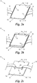
- the Fig. 2a to 6 show parts of the holder 3 in detail.
- the holder 3 is essentially formed by a combination of a carrier part 5 (FIG. Fig. 2a to 2d ), a cap 6 ( Fig. 3a and 3b ) and a seal 7 ( Fig. 5 ) educated.
- the carrier part 5 has a carrier plate 8 and a fastening collar 9. With the fastening collar 9, the carrier part 5 is mounted on the vehicle part 4.
- the cap 6 has according to the examples of Fig. 3a and 3b a transparent field of view 10 and a peripheral edge 11.
- the cap 6 can be anchored to the support plate 8, wherein the edge 11 surrounds the support plate 8 circumferentially.
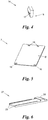
- the seal 7, which in the example of Fig. 5 plate-shaped and made of rubber is inserted between the cap 6 and support plate 8 and thereby seals a formed in the anchored state between the cap 6 and support plate 8 area D for the document 2 against external influences, in particular weathering from.
- the visibly leading document 2 is interposed when anchoring the cap 6 to the support plate 8 in this protected area D, the seal 7 between the support plate 8 and document 2 comes to rest.
- Has the seal 7 as an alternative to the example of Fig. 4 a central recess, so the document 2 can be inserted at least predominantly in this recess between the support plate 8 and cap 6.
- the support plate 8 has in its edge region in the direction of the cap 6 projecting sealing webs 13.
- the sealing webs are arranged only in the lateral edge region of the support plate 8; in the alternative example of the Fig. 2b the sealing webs 13 form a circumferential frame. In any case, press in the anchored state, the sealing webs 13, the seal 7 to the cap 6 and thereby enhance the effect of the seal. 7
- Fig. 2a to 4 is the snap connection 12 by within the outer edge 11 over the circumference of the cap 6 distributed, from the cap 6 towering snap hook 14 and the snap hook 14 corresponding snap openings 15 formed in the support plate 8, which are outside of said sealing ridges 13.
- the seal has 7 to the snap openings 15 corresponding openings 16 for the passage of the snap hook 14th
- the snap connection 12 could alternatively by, for example, formed by said edge 11, the support plate 8 projecting towards snap lugs, which lock when anchoring to the support plate 8, or the like. be formed (not shown).
- the snap hook 14 can, as in the example of Fig. 3b be sawtooth, or they are as in the example of Fig. 4 undercut, so that there are spreading wings 17 formed, which engage inseparably when anchoring behind the snap openings 15.
- Sawtooth or spreader wings 17 are formed on one side on the snap hook 14 in the illustrated examples; alternatively, these forms could be multi-sided or even circumferential on the snap-action hooks 14.
- the snap hooks 14 and the snap openings 15 in the illustrated examples have approximately rectangular cross section; this could alternatively be, for example, oval, square or round or have another, in particular asymmetric shape.
- the snap openings 15 may be funnel-shaped.
- a predetermined breaking point 18 may be provided to ensure that the snap connection 12 is non-destructively releasable; in the example of Fig. 4 the predetermined breaking point 18 is formed by a cross section of the snap-action hook 14 which tapers in the direction of the cap 6.
- Alternative embodiments of a predetermined breaking point 18 are well known to those skilled in the art.
- Fig. 2a to 3b has the snap connection 12 four snap hooks 14 and snap openings 15, of which two are arranged on opposite sides of the substantially rectangular cap 6 and support plate 8 respectively.
- the snap hooks 14 are optionally distributed non-rotationally symmetrically over the circumference of the cap 6, for example by the snap hook 14 on one side smaller mutual distance than on the opposite side of the cap 6.
- the same is true for the corresponding snap openings 15 (and openings 16 of Seal 7).
- the cap 6 can only be anchored to the support plate 8 in a single orientation, ie anchoring in relation to the support plate 8 twisted orientation is impossible.
- the snap hooks 14 may be otherwise distributed over the periphery of the cap 6, e.g. rotationally symmetric, i. that the cap 6 can be anchored in different orientations on the support plate 8. Further, carrier plate 8 and cap 6 could be non-rectangular, e.g. round, oval or any other shape.
- Fig. 2c is on the mounting sleeve for secure attachment of the support member 5 to a vehicle part 4 with a round cross-section optionally a fitting 19, for example, a ridge with rounded edge 20 is formed.
- the carrier plate 8 and the mounting sleeve 9 are optionally made of plastic, in particular a weather and UV light-resistant plastic, which is free of fire accelerators and temperatures in the range of at least between -30 and + 50 ° C without relevant Functional impairment or deformation withstands.
- plastics of this type are known to the person skilled in the art.
- the cap 6 is made, which in the examples of Fig. 3a and 3b in its entirety is made of transparent plastic; alternatively, it could be transparent only in the area of the field of view 10.
- the cap 6 of the example of Fig. 3a has on its outer side facing away from the support plate 8 optional recesses 21 next to the field of view 10, in which, if desired, additional labels or stickers or signs can be attached.
- the cap 6 further optionally in the direction of the support plate 8 projecting guide webs 22, between which the document 2 is securely guided against slipping.
- the fastening collar 9 optionally comprises a flexible belt 23 on which saw teeth 24 are formed, and a clasp 25 on which a pawl 26 is formed.
- the belt 23 is placed when mounting around the vehicle part 4 and inserted into the clasp 25, wherein in each case a sawtooth 24 is latched to the pawl 26 by tightening the belt 23, ie passing through the clasp 25 and latching each of a subsequent sawtooth 24, the Carrier part 5 fixed seat on the vehicle part 4 attained.
- the mounting sleeve 9 could, for example, by a perforated belt and a buckle, by a clamp or the like. be formed.
- the pawl 26 is located on the side facing away from the support plate 8 side of the clasp 25 and is therefore inaccessible after mounting the support member 5 on the vehicle part 4 and thus not destructively unlatched.
- a slip guard 27 On its side facing away from the support plate 8 side of the belt 23 optionally a slip guard 27 according to Fig. 6 have to rest on the vehicle part 4.
- the anti-slip device 27 is made of rubber, for example, and can have a bridge 28 for attachment to the belt 23, through which the belt 23 is pushed. Further, the anti-skid device 27, if desired, at least partially have lateral webs 29, which further complicate slipping relative to the belt 23.
Landscapes
- Engineering & Computer Science (AREA)
- Mechanical Engineering (AREA)
- Business, Economics & Management (AREA)
- Accounting & Taxation (AREA)
- Marketing (AREA)
- Physics & Mathematics (AREA)
- General Physics & Mathematics (AREA)
- Theoretical Computer Science (AREA)
- Clamps And Clips (AREA)
- Road Signs Or Road Markings (AREA)
Abstract
Description
- Die vorliegende Erfindung betrifft eine Halterung zum Verankern eines sichtbar zu führenden Dokuments an einem Fahrzeug, insbesondere an einem einspurigen Kraftfahrzeug.
- Vielerorts ist es notwendig bzw. gesetzlich vorgeschrieben, Dokumente an einem Fahrzeug sichtbar zu führen. Solche Dokumente sind beispielsweise Mautvignetten, Prüfplaketten (z.B. Fahrzeug- bzw. Abgas-Prüfplaketten), Berechtigungsnachweise (z.B. Park- oder Einfahrtsberechtigungen), amtliche Urkunden, Versicherungsbestätigungen od.dgl. Die Dokumente sind häufig aus Kunststoff, manchmal aus Metall(folie) oder sogar aus Papier; sie können optional elektronische Bauelemente umfassen. Ferner sind manche derartige Dokumente selbstklebend, u.zw. an ihrer Vorder- oder ihrer Rückseite, wogegen andere keine Hafteigenschaften aufweisen.
- Insbesondere bei einem mehrspurigen Kraftfahrzeug kann ein Dokument der genannten Art vor Diebstahl, Vandalismus und/oder Witterung weitgehend geschützt oft im Innenraum, z.B. an der Innenseite der Windschutzscheibe, sichtbar geführt werden. Hingegen ist dies in anderen Fällen, z.B. wenn das Dokument an der Rückseite klebend ist oder bei einem offenen Fahrzeug, z.B. einspurigen Fahrzeug bzw. Kraftfahrzeug, nicht möglich oder von Gesetzes wegen anders vorgesehen. In diesen Fällen ist das Dokument an der Außenseite des Fahrzeugs in einer Weise zu verankern, dass es sichtbar ist, und dabei entsprechend zu schützen.
- Außenseitig zu verankernde Dokumente werden heute meist an einem lackierten, pulverbeschichteten, eloxierten oder verchromten Fahrzeugteil angebracht. Um unerwünschte Beschädigungen oder dauerhafte Klebespuren an der Oberfläche des Fahrzeugteils beim Austauschen oder Entfernen eines Dokuments zu vermeiden, ist insbesondere für rückseitig selbstklebende Dokumente unter dem Namen FixItEasy® eine Halterung der Firma RD Handelgesellschaft aus Österreich bekannt. Diese Halterung wird z.B. an einem Gabelstandrohr eines einspurigen Kraftfahrzeugs klebstofffrei und sicher montiert und bietet eine ebene Fläche zum Aufkleben des Dokuments. Dabei bleibt das Dokument den Witterungsbedingungen und dem direkten Zugriff vom außen ausgesetzt und könnte folglich beschädigt oder - je nach Klebstoff - zumindest teilweise abgelöst werden.
- Die Erfindung setzt sich zum Ziel, eine Halterung für ein Dokument zu schaffen, welche dieses zuverlässig vor äußeren Einflüssen schützt.
- Dieses Ziel wird mit einer Halterung der einleitend genannten Art erreicht, welche sich auszeichnet durch die Kombination aus:
- einem Trägerteil mit einer Trägerplatte und einer Befestigungsmanschette zum Montieren des Trägerteils an einem Teil des Fahrzeugs;
- einer unter Zwischenlegen des Dokuments an der Trägerplatte mithilfe einer Schnappverbindung verankerbaren Abdeckkappe mit einem transparenten Sichtfeld und einem die Trägerplatte umlaufend einfassenden Rand; und
- einer zwischen Abdeckkappe und Trägerplatte einlegbaren Dichtung;
- wobei die Trägerplatte in ihrem Randbereich in Richtung der Abdeckkappe abstehende Dichtstege zum Anpressen der Dichtung an die Abdeckkappe hat.
- Mit der Halterung kann das Dokument dauerhaft sichtbar am Fahrzeug geführt werden und ist fest daran verankert. Trotz jederzeitiger Sichtbarkeit wird das Dokument vor direktem Zugriff von außen geschützt. Der umlaufende Rand, die Dichtung und die Dichtstege halten Wettereinflüsse vom zwischen Trägerplatte und Abdeckkappe eingelegten Dokument zuverlässig fern. Die Halterung ist somit auch für Dokumente aus - nicht wasserfestem - Papier geeignet und kann in unterschiedlichen, an beliebige Dokumente - z.B. runde, rechteckige, asymmetrische - angepassten Formen hergestellt werden. Da ferner ein laterales Verschieben der Abdeckkappe gegenüber der Trägerplatte aufgrund des umlaufenden Randes unmöglich ist, wird neben dem Eindringen von Feuchtigkeit und Schmutz auch ein Eingreifen zwecks Manipulation, Diebstahls oder Vandalismus erschwert.
- Besonders günstig ist es, wenn die Dichtstege einen umlaufenden Rahmen bilden. Die Halterung schafft dadurch einen besonders zuverlässig abgedichteten Bereich für das Dokument.
- In einer bevorzugten Ausführungsform ist die Schnappverbindung durch innerhalb des Randes über den Umfang verteilte, von der Abdeckkappe hochragende Schnapphaken und dazu korrespondierende, außerhalb der Dichtstege liegende Schnappöffnungen in der Trägerplatte gebildet, hinter welchen die Schnapphaken unlösbar verrasten. Auf diese Weise kann das Dokument der Halterung nicht ohne Zerstörung derselben entnommen werden und ein Übertragen des Dokuments mitsamt der Halterung auf ein anderes Fahrzeug ist ausgeschlossen. Dadurch und weil die Schnapphaken innerhalb des Randes über den Umfang der Abdeckkappe verteilt sind, sodass sie nach dem Montieren des Trägerteils an dem Fahrzeugteil und dem Verankern der Abdeckkappe an der Trägerplatte schwierig oder gar nicht zugänglich sind, ist auch ein missbräuchliches Weiterverwenden des Dokuments wesentlich erschwert. Manipulation, Diebstahl und/oder Vandalismus wird dadurch weiter entgegenwirkt.
- Dabei ist vorteilhaft, wenn die Schnapphaken Spreizflügel haben, welche hinter den Schnappöffnungen unlösbar verrasten. Dies führt zu einer einfach anwendbaren, besonders sicheren, nicht zerstörungsfrei lösbaren Schnappverbindung.
- Zur Vereinfachung der Montage der Halterung und als Schutz gegen ein verdrehtes Verankern der Abdeckkappe an der Trägerplatte ist es günstig, wenn die Schnapphaken nicht-rotationssymmetrisch über den Umfang der Abdeckkappe verteilt sind. Auf diese Weise kann die Abdeckkappe nur in einer, nämlich der vorgesehenen Ausrichtung an der Trägerplatte verankert werden.
- Bevorzugt sind die Trägerplatte und die Befestigungsmanschette einstückig aus Kunststoff gefertigt. Trägerplatte und Befestigungsmanschette sind so voneinander nicht zerstörungsfrei trennbar und dabei kostengünstig herstellbar.
- Um ein Verrutschen des Dokuments beim Verankern an dem Fahrzeug und im Betrieb des Fahrzeugs zu verhindern, ist es vorteilhaft, wenn die Abdeckkappe in Richtung der Trägerplatte abstehende Führungsstege für das Dokument hat. Das Dokument bleibt auf diese Weise zuverlässig im transparenten Sichtfeld sichtbar.
- In einer bevorzugten Ausführungsform umfasst die Befestigungsmanschette einen flexiblen Riemen mit Sägezähnen und eine Schließe mit einer Klinke. Die Klinke ermöglicht ein einfaches, dauerhaftes Verrasten und eine solche Befestigungsmanschette ein sicheres, an den Fahrzeugteil und seinen Umfang anpassbares Montieren des Trägerteils am Fahrzeug.
- Besonders günstig ist dabei, wenn die Klinke an der von der Trägerplatte abgewandten Seite der Schließe liegt. Auf diese Weise ist die Klinke nach dem Montieren des Trägerteils an dem Fahrzeugteil nicht mehr zugänglich und die Befestigungsmanschette folglich nicht zerstörungsfrei zu öffnen, sodass die gesamte Halterung mitsamt dem Dokument nicht zerstörungsfrei vom Fahrzeug abgenommen und weiterverwendet werden kann.
- Um einen besonders sicheren Sitz des Trägerteils und damit der Halterung an dem Fahrzeugteil sicherzustellen, hat bevorzugt der Riemen an seiner von der Trägerplatte abgewandten Seite ferner eine Rutschsicherung zur Anlage an dem Fahrzeugteil. Eine solche Rutschsicherung kann beispielsweise durch einen am Riemen fixierten Streifen aus Gummi realisiert sein.
- Die Erfindung wird nachfolgend anhand von in den beigeschlossenen Zeichnungen dargestellten Ausführungsbeispielen näher erläutert. In den Zeichnungen zeigen:
-
Fig. 1 ein Fahrzeug mit einer erfindungsgemäßen Halterung für ein Dokument in einer Seitenansicht; - die
Fig. 2a bis 2d Varianten eines Trägerteils der Halterung vonFig. 1 in einer ausschnittsweisen Perspektivansicht der Vorder- (Fig. 2a bzw. 2b) und der Rückseite (Fig. 2c ) bzw. in einer Perspektivansicht der Rückseite im Ganzen (Fig. 2d ); - die
Fig. 3a und 3b eine Abdeckkappe der Halterung vonFig. 1 in einer Perspektivansicht der Vorder- (Fig. 3a ) bzw. der Rückseite (Fig. 3b ); -
Fig. 4 ein Beispiel für einen Schnapphaken der Abdeckkappe derFig. 3a und 3b in einer Perspektivansicht; -
Fig. 5 eine Dichtung der Halterung vonFig. 1 in einer Perspektivansicht; und -
Fig. 6 eine Rutschsicherung des Trägerteils vonFig. 2a bis 2d in einer Perspektivansicht. - Die
Fig. 1 zeigt ein Fahrzeug 1 - z.B. ein einspuriges Fahrzeug, insbesondere Kraftfahrzeug - mit einem daran sichtbar geführten Dokument 2. Das Dokument 2 ist mithilfe einer Halterung 3 an einem Fahrzeugteil 4 - hier: einem Gabelstandrohr bzw. einem Gabel- oder Lenkholm - verankert. Das Dokument 2 ist optional selbstklebend und kann z.B. aus Kunststoff, Papier und/oder Metall(folie) und dabei beschriftet und/oder elektronisch über Funk auslesbar sein. Es kann sich dabei z.B. um eine Mautvignette, eine Prüfplakette (z.B. eine Fahrzeug- bzw. Abgas-Prüfplakette), eine amtliche Urkunde, einen Berechtigungsnachweis (z.B. eine Park- oder Einfahrtsberechtigung), eine Versicherungsbestätigung od.dgl. handeln. - Die
Fig. 2a bis 6 zeigen Teile der Halterung 3 im Einzelnen. Die Halterung 3 wird im Wesentlichen durch eine Kombination aus einem Trägerteil 5 (Fig. 2a bis 2d ), einer Abdeckkappe 6 (Fig. 3a und 3b ) und einer Dichtung 7 (Fig. 5 ) gebildet. - In den Beispielen der
Fig. 2a bis 2d hat der Trägerteil 5 eine Trägerplatte 8 und eine Befestigungsmanschette 9. Mit der Befestigungsmanschette 9 wird der Trägerteil 5 an dem Fahrzeugteil 4 montiert. - Die Abdeckkappe 6 hat gemäß den Beispielen der
Fig. 3a und 3b ein transparentes Sichtfeld 10 und einen umlaufenden Rand 11. Mithilfe einer Schnappverbindung 12 ist die Abdeckkappe 6 an der Trägerplatte 8 verankerbar, wobei der Rand 11 die Trägerplatte 8 umlaufend einfasst. Dabei ist ferner die Dichtung 7, welche im Beispiel derFig. 5 plattenförmig und aus Gummi ist, zwischen Abdeckkappe 6 und Trägerplatte 8 eingelegt und dichtet dadurch einen im verankerten Zustand zwischen Abdeckkappe 6 und Trägerplatte 8 gebildeten Bereich D für das Dokument 2 gegen Einflüsse von außen, insbesondere Witterungseinflüsse, ab. Es versteht sich, dass das sichtbar zu führende Dokument 2 beim Verankern der Abdeckkappe 6 an der Trägerplatte 8 in diesem geschützten Bereich D zwischengelegt wird, wobei die Dichtung 7 zwischen Trägerplatte 8 und Dokument 2 zu liegen kommt. Hat die Dichtung 7 alternativ zu dem Beispiel derFig. 4 eine mittige Aussparung, so kann das Dokument 2 zumindest überwiegend in dieser Aussparung zwischen Trägerplatte 8 und Abdeckkappe 6 eingelegt werden. - Die Trägerplatte 8 hat in ihrem Randbereich in Richtung der Abdeckkappe 6 abstehende Dichtstege 13. Im Beispiel der
Fig. 2a sind die Dichtstege bloß im seitlichen Randbereich der Trägerplatte 8 angeordnet; im dazu alternativen Beispiel derFig. 2b bilden die Dichtstege 13 einen umlaufenden Rahmen. Jedenfalls pressen im verankerten Zustand die Dichtstege 13 die Dichtung 7 an die Abdeckkappe 6 und verstärken dadurch die Wirkung der Dichtung 7. - In den Beispielen der
Fig. 2a bis 4 ist die Schnappverbindung 12 durch innerhalb des äußeren Randes 11 über den Umfang der Abdeckkappe 6 verteilte, von der Abdeckkappe 6 hochragende Schnapphaken 14 und zu den Schnapphaken 14 korrespondierende Schnappöffnungen 15 in der Trägerplatte 8 gebildet, welche außerhalb der genannten Dichtstege 13 liegen. Beim Verankern der Abdeckkappe 6 an der Trägerplatte 8 verrasten die Schnapphaken 14 hinter den Schnappöffnungen 15 unlösbar, d.h. nicht zerstörungsfrei lösbar. Wie im Beispiel derFig. 5 gezeigt, hat die Dichtung 7 dabei zu den Schnappöffnungen 15 korrespondierende Öffnungen 16 für den Durchtritt der Schnapphaken 14. - Die Schnappverbindung 12 könnte alternativ z.B. durch am genannten Rand 11 ausgebildete, zur Trägerplatte 8 hin auskragende Schnappnasen, welche beim Verankern an der Trägerplatte 8 verrasten, od.dgl. gebildet sein (nicht dargestellt).
- Die Schnapphaken 14 können wie im Beispiel der
Fig. 3b sägezahnförmig sein, oder sie sind wie im Beispiel derFig. 4 hinterschnitten, sodass daran Spreizflügel 17 gebildet sind, welche beim Verankern hinter den Schnappöffnungen 15 unlösbar verrasten. Sägezahnform bzw. Spreizflügel 17 sind in den dargestellten Beispielen einseitig an den Schnapphaken 14 ausgebildet; alternativ könnten diese Formen an den Schnapphaken 14 mehrseitig oder sogar umlaufend sein. Ferner haben die Schnapphaken 14 und die Schnappöffnungen 15 in den dargestellten Beispielen etwa rechteckigen Querschnitt; dieser könnte alternativ z.B. oval, quadratisch oder rund sein oder eine andere, insbesondere asymmetrische Form haben. Optional können die Schnappöffnungen 15 trichterförmg sein. Überdies kann an der Schnappverbindung 12, falls erforderlich, eine Sollbruchstelle 18 vorgesehen sein, um sicherzustellen, dass die Schnappverbindung 12 nicht-zerstörungsfrei lösbar ist; im Beispiel derFig. 4 ist die Sollbruchstelle 18 durch einen sich in Richtung zur Abdeckkappe 6 hin verjüngenden Querschnitt des Schnapphakens 14 gebildet. Alternative Ausgestaltungen einer Sollbruchstelle 18 sind dem Fachmann bestens bekannt. - In den Beispielen der
Fig. 2a bis 3b hat die Schnappverbindung 12 vier Schnapphaken 14 bzw. Schnappöffnungen 15, von denen jeweils zwei an gegenüberliegenden Seiten der im Wesentlichen rechteckigen Abdeckkappe 6 bzw. Trägerplatte 8 angeordnet sind. Dabei sind die Schnapphaken 14 optional nicht-rotationssymmetrisch über den Umfang der Abdeckkappe 6 verteilt, z.B. indem die Schnapphaken 14 an einer Seite geringeren gegenseitigen Abstand haben als an der gegenüberliegenden Seite der Abdeckkappe 6. Dasselbe gilt für die korrespondierenden Schnappöffnungen 15 (und Öffnungen 16 der Dichtung 7). Infolgedessen kann die Abdeckkappe 6 bloß in einer einzigen Ausrichtung an der Trägerplatte 8 verankert werden, d.h. ein Verankern in gegenüber der Trägerplatte 8 verdrehter Ausrichtung ist unmöglich. - Es versteht sich, dass die Schnapphaken 14 in anderer Weise über den Umfang der Abdeckkappe 6 verteilt sein können, z.B. rotationssymmetrisch, d.h. dass die Abdeckkappe 6 in verschiedenen Ausrichtungen an der Trägerplatte 8 verankerbar ist. Ferner könnten Trägerplatte 8 und Abdeckkappe 6 nicht-rechteckig sein, z.B. rund, oval oder beliebig anders geformt.
- Im Folgenden werden anhand der beispielhaften Darstellungen der
Fig. 2c bis 6 weitere Ausführungsvarianten erläutert. - Gemäß dem Beispiel der
Fig. 2c ist an der Befestigungsmanschette zur sicheren Befestigung des Trägerteils 5 an einem Fahrzeugteil 4 mit rundem Querschnitt optional ein Formstück 19, z.B. ein Steg mit abgerundeter Kante 20, ausgebildet. - Wie im Beispiel der
Fig. 2d gezeigt, sind optional die Trägerplatte 8 und die Befestigungsmanschette 9 einstückig aus Kunststoff, insbesondere einem Witterungs- und UV-Licht-beständigen Kunststoff, gefertigt, welcher frei von Brandbeschleunigern ist und Temperaturen im Bereich von zumindest zwischen -30 und +50° Celsius ohne relevante Funktionsbeeinträchtigung oder Verformung standhält. Kunststoffe solcher Art sind dem Fachmann bekannt. Aus Kunststoff mit ebensolchen Eigenschaften ist optional auch die Abdeckkappe 6 gefertigt, welche in den Beispielen derFig. 3a und 3b in ihrer Gesamtheit aus transparentem Kunststoff ist; alternativ könnte sie bloß im Bereich des Sichtfeldes 10 transparent sein. - Die Abdeckkappe 6 des Beispiels der
Fig. 3a hat an ihrer der Trägerplatte 8 abgewandten Außenseite optionale Vertiefungen 21 neben dem Sichtfeld 10, in welche, falls gewünscht, zusätzliche Beschriftungen bzw. Aufkleber oder Schilder angebracht werden können. - Wie im Beispiel der
Fig. 3b gezeigt, hat die Abdeckkappe 6 ferner optional in Richtung der Trägerplatte 8 abstehende Führungsstege 22, zwischen welchen das Dokument 2 gegen Verrutschen sicher geführt ist. Die Führungsstege 22 können wie im dargestellten Beispiel die Abdeckkappe 6 zur Gänze oder alternativ nur teilweise durchqueren. - Zurückkommend auf das Beispiel der
Fig. 2d umfasst die Befestigungsmanschette 9 optional einen flexiblen Riemen 23, an welchem Sägezähne 24 ausgebildet sind, und eine Schließe 25, an welcher eine Klinke 26 ausgebildet ist. Der Riemen 23 wird beim Montieren um den Fahrzeugteil 4 gelegt und in die Schließe 25 eingeführt, wobei jeweils ein Sägezahn 24 an der Klinke 26 verrastet bis durch Festziehen des Riemens 23, d.h. Weiterziehen durch die Schließe 25 und Verrasten jeweils eines folgenden Sägezahns 24, der Trägerteil 5 festen Sitz am Fahrzeugteil 4 erlangt. Alternativ könnten die Befestigungsmanschette 9 beispielsweise durch einen gelochten Riemen und eine Schnalle, durch eine Schelle od.dgl. gebildet sein. - Im gezeigten Beispiel liegt die Klinke 26 an der von der Trägerplatte 8 abgewandten Seite der Schließe 25 und ist deshalb nach dem Montieren des Trägerteils 5 an dem Fahrzeugteil 4 unzugänglich und somit nicht zerstörungsfrei ausklinkbar.
- An seiner von der Trägerplatte 8 abgewandte Seite kann der Riemen 23 optional eine Rutschsicherung 27 gemäß
Fig. 6 zur Anlage an dem Fahrzeugteil 4 haben. Die Rutschsicherung 27 ist z.B. aus Gummi und kann zur Befestigung an dem Riemen 23 eine Brücke 28 haben, durch welche der Riemen 23 geschoben wird. Ferner kann die Rutschsicherung 27, falls gewünscht, zumindest abschnittsweise seitliche Stege 29 haben, welche ein Verrutschen gegenüber dem Riemen 23 weiter erschweren. - Die Erfindung ist nicht auf die dargestellten Ausführungsformen beschränkt, sondern umfasst alle Varianten, Kombinationen und Modifikationen, die in den Rahmen der angeschlossenen Ansprüche fallen.
Claims (10)
- Halterung zum Verankern eines sichtbar zu führenden Dokuments an einem Fahrzeug, insbesondere an einem einspurigen Kraftfahrzeug, gekennzeichnet durch die Kombination aus:einem Trägerteil (5) mit einer Trägerplatte (8) und einer Befestigungsmanschette (9) zum Montieren des Trägerteils (5) an einem Teil (4) des Fahrzeugs (1);einer unter Zwischenlegen des Dokuments an der Trägerplatte (8) mithilfe einer Schnappverbindung (12) verankerbaren Abdeckkappe (6) mit einem transparenten Sichtfeld (10) und einem die Trägerplatte (8) umlaufend einfassenden Rand (11); undeiner zwischen Abdeckkappe (6) und Trägerplatte (8) einlegbaren Dichtung (7);wobei die Trägerplatte (8) in ihrem Randbereich in Richtung der Abdeckkappe (6) abstehende Dichtstege (13) zum Anpressen der Dichtung (7) an die Abdeckkappe (6) hat.
- Halterung nach Anspruch 1, dadurch gekennzeichnet, dass die Dichtstege (13) einen umlaufenden Rahmen bilden.
- Halterung nach Anspruch 1 oder 2, dadurch gekennzeichnet, dass die Schnappverbindung (12) durch innerhalb des Randes (11) über den Umfang verteilte, von der Abdeckkappe (6) hochragende Schnapphaken (14) und dazu korrespondierende, außerhalb der Dichtstege (13) liegende Schnappöffnungen (15) in der Trägerplatte (8) gebildet ist, hinter welchen die Schnapphaken (14) unlösbar verrasten.
- Halterung nach Anspruch 3, dadurch gekennzeichnet, dass die Schnapphaken (14) Spreizflügel (17) haben, welche hinter den Schnappöffnungen (15) unlösbar verrasten.
- Halterung nach Anspruch 3 oder 4, dadurch gekennzeichnet, dass die Schnapphaken (14) nicht-rotationssymmetrisch über den Umfang der Abdeckkappe (6) verteilt sind.
- Halterung nach einem der Ansprüche 1 bis 5, dadurch gekennzeichnet, dass die Trägerplatte (8) und die Befestigungsmanschette (9) einstückig aus Kunststoff gefertigt sind.
- Halterung nach einem der Ansprüche 1 bis 6, dadurch gekennzeichnet, dass die Abdeckkappe (6) in Richtung der Trägerplatte (8) abstehende Führungsstege (22) für das Dokument (2) hat.
- Halterung nach einem der Ansprüche 1 bis 7, dadurch gekennzeichnet, dass die Befestigungsmanschette (9) einen flexiblen Riemen (23) mit Sägezähnen (24) und eine Schließe (25) mit einer Klinke (26) umfasst.
- Halterung nach Anspruch 8, dadurch gekennzeichnet, dass die Klinke (26) an der von der Trägerplatte (8) abgewandten Seite der Schließe (25) liegt.
- Halterung nach Anspruch 8 oder 9, dadurch gekennzeichnet, dass der Riemen (23) an seiner von der Trägerplatte (8) abgewandten Seite ferner eine Rutschsicherung (27) zur Anlage an dem Fahrzeugteil (4) hat.
Applications Claiming Priority (2)
| Application Number | Priority Date | Filing Date | Title |
|---|---|---|---|
| AT600142016 | 2016-12-19 | ||
| ATA50433/2017A AT519358B1 (de) | 2016-12-19 | 2017-05-22 | Halterung zum Verankern eines Dokuments an einem Fahrzeug |
Publications (2)
| Publication Number | Publication Date |
|---|---|
| EP3335940A1 true EP3335940A1 (de) | 2018-06-20 |
| EP3335940B1 EP3335940B1 (de) | 2019-07-10 |
Family
ID=60473378
Family Applications (1)
| Application Number | Title | Priority Date | Filing Date |
|---|---|---|---|
| EP17203715.2A Active EP3335940B1 (de) | 2016-12-19 | 2017-11-27 | Halterung zum verankern eines dokuments an einem fahrzeug |
Country Status (1)
| Country | Link |
|---|---|
| EP (1) | EP3335940B1 (de) |
Citations (4)
| Publication number | Priority date | Publication date | Assignee | Title |
|---|---|---|---|---|
| DE29804748U1 (de) * | 1998-03-17 | 1998-09-03 | Meythaler, Reiner, 79104 Freiburg | Abschließbarer Parkscheinhalter mit Schutz-Sichthülle für Motorräder, Motorroller und Trikes an runden Fahrzeugteilen oder sonstigen Fahrzeugflächen |
| DE20307979U1 (de) * | 2003-05-22 | 2003-09-11 | Silvestre, Raffaele, 71691 Freiberg | Abschließbare Vorrichtung zur sicheren Befestigung eines Parkscheins am Motorrad/Mofa |
| GB2493330A (en) * | 2011-07-24 | 2013-02-06 | Trudi Anita Hall | Secure Weatherproof Parking Ticket or Parking Permit Holder for Motorcycle, etc. |
| US20140196332A1 (en) * | 2010-05-11 | 2014-07-17 | Oxk, Llc | System and Method for Mounting a Badge on a Vehicle |
-
2017
- 2017-11-27 EP EP17203715.2A patent/EP3335940B1/de active Active
Patent Citations (4)
| Publication number | Priority date | Publication date | Assignee | Title |
|---|---|---|---|---|
| DE29804748U1 (de) * | 1998-03-17 | 1998-09-03 | Meythaler, Reiner, 79104 Freiburg | Abschließbarer Parkscheinhalter mit Schutz-Sichthülle für Motorräder, Motorroller und Trikes an runden Fahrzeugteilen oder sonstigen Fahrzeugflächen |
| DE20307979U1 (de) * | 2003-05-22 | 2003-09-11 | Silvestre, Raffaele, 71691 Freiberg | Abschließbare Vorrichtung zur sicheren Befestigung eines Parkscheins am Motorrad/Mofa |
| US20140196332A1 (en) * | 2010-05-11 | 2014-07-17 | Oxk, Llc | System and Method for Mounting a Badge on a Vehicle |
| GB2493330A (en) * | 2011-07-24 | 2013-02-06 | Trudi Anita Hall | Secure Weatherproof Parking Ticket or Parking Permit Holder for Motorcycle, etc. |
Also Published As
| Publication number | Publication date |
|---|---|
| EP3335940B1 (de) | 2019-07-10 |
Similar Documents
| Publication | Publication Date | Title |
|---|---|---|
| DE102012010893A1 (de) | Befestigungssystem | |
| DE102007011109A1 (de) | Folienplakette für eine Airbagabdeckung | |
| DE102007008862A1 (de) | Unfallsensor | |
| EP2525991B1 (de) | Kfz-scheibeneinheit mit befestigung für zierleiste | |
| EP3335940B1 (de) | Halterung zum verankern eines dokuments an einem fahrzeug | |
| DE202005018240U1 (de) | Baugruppe zur Befestigung eines Bauteils | |
| AT519358B1 (de) | Halterung zum Verankern eines Dokuments an einem Fahrzeug | |
| EP2703266A1 (de) | Kabelabdeckungsvorrichtung | |
| DE202017107701U1 (de) | Insektenschutzvorrichtung | |
| DE102013201561A1 (de) | Befestigungselement | |
| EP1688715B1 (de) | Plombe zur Sicherung eines Energieverbrauchmessgeräts | |
| CH701598A1 (de) | Wechselschildhalter für Fahrzeug-Kennzeichen. | |
| WO2011107552A1 (de) | Schild und befestigungsvorrichtung | |
| AT403875B (de) | Clips | |
| DE102005046468A1 (de) | Namensschild | |
| DE102010005309A1 (de) | Verkleidungsteil mit mindestens einem Befestigungsmittel zur Befestigung an einer Fahrzeugkarosserie | |
| DE19809902B4 (de) | Außenrückblickspiegel | |
| AT515844A1 (de) | Emblemträger | |
| EP1052166A3 (de) | Anordnung zur Befestigung einer Kunststoffscheibe an einem Rahmen, insbesondere einem Karosserieflansch | |
| DE3446729A1 (de) | Einrichtung zur diebstahlsicheren befestigung von kennzeichenschildern fuer kraftfahrzeuge | |
| DE202008008701U1 (de) | Halteeinrichtung für Schilder | |
| DE102007042834A1 (de) | Innenausstattungsteil für ein Fahrzeug, insbesondere Kraftfahrzeug | |
| AT521600B1 (de) | Verfahren zum Befestigen eines Kennzeichens in einem Kennzeichenhalter, | |
| DE29817420U1 (de) | Befestigungseinrichtung bzw. Anordnung mit dieser | |
| EP3202706A1 (de) | Anordnung, kennzeichnungslasche und verwendung einer kennzeichnungslasche zur kennzeichnung eines zapfventils |
Legal Events
| Date | Code | Title | Description |
|---|---|---|---|
| PUAI | Public reference made under article 153(3) epc to a published international application that has entered the european phase |
Free format text: ORIGINAL CODE: 0009012 |
|
| STAA | Information on the status of an ep patent application or granted ep patent |
Free format text: STATUS: THE APPLICATION HAS BEEN PUBLISHED |
|
| AK | Designated contracting states |
Kind code of ref document: A1 Designated state(s): AL AT BE BG CH CY CZ DE DK EE ES FI FR GB GR HR HU IE IS IT LI LT LU LV MC MK MT NL NO PL PT RO RS SE SI SK SM TR |
|
| AX | Request for extension of the european patent |
Extension state: BA ME |
|
| STAA | Information on the status of an ep patent application or granted ep patent |
Free format text: STATUS: REQUEST FOR EXAMINATION WAS MADE |
|
| 17P | Request for examination filed |
Effective date: 20181121 |
|
| RBV | Designated contracting states (corrected) |
Designated state(s): AL AT BE BG CH CY CZ DE DK EE ES FI FR GB GR HR HU IE IS IT LI LT LU LV MC MK MT NL NO PL PT RO RS SE SI SK SM TR |
|
| GRAP | Despatch of communication of intention to grant a patent |
Free format text: ORIGINAL CODE: EPIDOSNIGR1 |
|
| STAA | Information on the status of an ep patent application or granted ep patent |
Free format text: STATUS: GRANT OF PATENT IS INTENDED |
|
| RIC1 | Information provided on ipc code assigned before grant |
Ipc: G09F 21/04 20060101ALI20190116BHEP Ipc: B62J 11/00 20060101ALI20190116BHEP Ipc: B60R 13/10 20060101AFI20190116BHEP |
|
| INTG | Intention to grant announced |
Effective date: 20190205 |
|
| GRAS | Grant fee paid |
Free format text: ORIGINAL CODE: EPIDOSNIGR3 |
|
| GRAA | (expected) grant |
Free format text: ORIGINAL CODE: 0009210 |
|
| STAA | Information on the status of an ep patent application or granted ep patent |
Free format text: STATUS: THE PATENT HAS BEEN GRANTED |
|
| AK | Designated contracting states |
Kind code of ref document: B1 Designated state(s): AL AT BE BG CH CY CZ DE DK EE ES FI FR GB GR HR HU IE IS IT LI LT LU LV MC MK MT NL NO PL PT RO RS SE SI SK SM TR |
|
| REG | Reference to a national code |
Ref country code: GB Ref legal event code: FG4D Free format text: NOT ENGLISH |
|
| REG | Reference to a national code |
Ref country code: CH Ref legal event code: EP Ref country code: AT Ref legal event code: REF Ref document number: 1153226 Country of ref document: AT Kind code of ref document: T Effective date: 20190715 |
|
| REG | Reference to a national code |
Ref country code: DE Ref legal event code: R096 Ref document number: 502017001747 Country of ref document: DE |
|
| REG | Reference to a national code |
Ref country code: IE Ref legal event code: FG4D Free format text: LANGUAGE OF EP DOCUMENT: GERMAN |
|
| REG | Reference to a national code |
Ref country code: NL Ref legal event code: MP Effective date: 20190710 |
|
| REG | Reference to a national code |
Ref country code: LT Ref legal event code: MG4D |
|
| PG25 | Lapsed in a contracting state [announced via postgrant information from national office to epo] |
Ref country code: NL Free format text: LAPSE BECAUSE OF FAILURE TO SUBMIT A TRANSLATION OF THE DESCRIPTION OR TO PAY THE FEE WITHIN THE PRESCRIBED TIME-LIMIT Effective date: 20190710 Ref country code: BG Free format text: LAPSE BECAUSE OF FAILURE TO SUBMIT A TRANSLATION OF THE DESCRIPTION OR TO PAY THE FEE WITHIN THE PRESCRIBED TIME-LIMIT Effective date: 20191010 Ref country code: LT Free format text: LAPSE BECAUSE OF FAILURE TO SUBMIT A TRANSLATION OF THE DESCRIPTION OR TO PAY THE FEE WITHIN THE PRESCRIBED TIME-LIMIT Effective date: 20190710 Ref country code: PT Free format text: LAPSE BECAUSE OF FAILURE TO SUBMIT A TRANSLATION OF THE DESCRIPTION OR TO PAY THE FEE WITHIN THE PRESCRIBED TIME-LIMIT Effective date: 20191111 Ref country code: HR Free format text: LAPSE BECAUSE OF FAILURE TO SUBMIT A TRANSLATION OF THE DESCRIPTION OR TO PAY THE FEE WITHIN THE PRESCRIBED TIME-LIMIT Effective date: 20190710 Ref country code: SE Free format text: LAPSE BECAUSE OF FAILURE TO SUBMIT A TRANSLATION OF THE DESCRIPTION OR TO PAY THE FEE WITHIN THE PRESCRIBED TIME-LIMIT Effective date: 20190710 Ref country code: NO Free format text: LAPSE BECAUSE OF FAILURE TO SUBMIT A TRANSLATION OF THE DESCRIPTION OR TO PAY THE FEE WITHIN THE PRESCRIBED TIME-LIMIT Effective date: 20191010 Ref country code: FI Free format text: LAPSE BECAUSE OF FAILURE TO SUBMIT A TRANSLATION OF THE DESCRIPTION OR TO PAY THE FEE WITHIN THE PRESCRIBED TIME-LIMIT Effective date: 20190710 |
|
| PG25 | Lapsed in a contracting state [announced via postgrant information from national office to epo] |
Ref country code: IS Free format text: LAPSE BECAUSE OF FAILURE TO SUBMIT A TRANSLATION OF THE DESCRIPTION OR TO PAY THE FEE WITHIN THE PRESCRIBED TIME-LIMIT Effective date: 20191110 Ref country code: RS Free format text: LAPSE BECAUSE OF FAILURE TO SUBMIT A TRANSLATION OF THE DESCRIPTION OR TO PAY THE FEE WITHIN THE PRESCRIBED TIME-LIMIT Effective date: 20190710 Ref country code: GR Free format text: LAPSE BECAUSE OF FAILURE TO SUBMIT A TRANSLATION OF THE DESCRIPTION OR TO PAY THE FEE WITHIN THE PRESCRIBED TIME-LIMIT Effective date: 20191011 Ref country code: AL Free format text: LAPSE BECAUSE OF FAILURE TO SUBMIT A TRANSLATION OF THE DESCRIPTION OR TO PAY THE FEE WITHIN THE PRESCRIBED TIME-LIMIT Effective date: 20190710 Ref country code: LV Free format text: LAPSE BECAUSE OF FAILURE TO SUBMIT A TRANSLATION OF THE DESCRIPTION OR TO PAY THE FEE WITHIN THE PRESCRIBED TIME-LIMIT Effective date: 20190710 |
|
| PG25 | Lapsed in a contracting state [announced via postgrant information from national office to epo] |
Ref country code: TR Free format text: LAPSE BECAUSE OF FAILURE TO SUBMIT A TRANSLATION OF THE DESCRIPTION OR TO PAY THE FEE WITHIN THE PRESCRIBED TIME-LIMIT Effective date: 20190710 |
|
| PG25 | Lapsed in a contracting state [announced via postgrant information from national office to epo] |
Ref country code: IT Free format text: LAPSE BECAUSE OF FAILURE TO SUBMIT A TRANSLATION OF THE DESCRIPTION OR TO PAY THE FEE WITHIN THE PRESCRIBED TIME-LIMIT Effective date: 20190710 Ref country code: RO Free format text: LAPSE BECAUSE OF FAILURE TO SUBMIT A TRANSLATION OF THE DESCRIPTION OR TO PAY THE FEE WITHIN THE PRESCRIBED TIME-LIMIT Effective date: 20190710 Ref country code: EE Free format text: LAPSE BECAUSE OF FAILURE TO SUBMIT A TRANSLATION OF THE DESCRIPTION OR TO PAY THE FEE WITHIN THE PRESCRIBED TIME-LIMIT Effective date: 20190710 Ref country code: DK Free format text: LAPSE BECAUSE OF FAILURE TO SUBMIT A TRANSLATION OF THE DESCRIPTION OR TO PAY THE FEE WITHIN THE PRESCRIBED TIME-LIMIT Effective date: 20190710 Ref country code: PL Free format text: LAPSE BECAUSE OF FAILURE TO SUBMIT A TRANSLATION OF THE DESCRIPTION OR TO PAY THE FEE WITHIN THE PRESCRIBED TIME-LIMIT Effective date: 20190710 |
|
| PG25 | Lapsed in a contracting state [announced via postgrant information from national office to epo] |
Ref country code: SK Free format text: LAPSE BECAUSE OF FAILURE TO SUBMIT A TRANSLATION OF THE DESCRIPTION OR TO PAY THE FEE WITHIN THE PRESCRIBED TIME-LIMIT Effective date: 20190710 Ref country code: SM Free format text: LAPSE BECAUSE OF FAILURE TO SUBMIT A TRANSLATION OF THE DESCRIPTION OR TO PAY THE FEE WITHIN THE PRESCRIBED TIME-LIMIT Effective date: 20190710 Ref country code: IS Free format text: LAPSE BECAUSE OF FAILURE TO SUBMIT A TRANSLATION OF THE DESCRIPTION OR TO PAY THE FEE WITHIN THE PRESCRIBED TIME-LIMIT Effective date: 20200224 Ref country code: CZ Free format text: LAPSE BECAUSE OF FAILURE TO SUBMIT A TRANSLATION OF THE DESCRIPTION OR TO PAY THE FEE WITHIN THE PRESCRIBED TIME-LIMIT Effective date: 20190710 |
|
| REG | Reference to a national code |
Ref country code: DE Ref legal event code: R097 Ref document number: 502017001747 Country of ref document: DE |
|
| PLBE | No opposition filed within time limit |
Free format text: ORIGINAL CODE: 0009261 |
|
| STAA | Information on the status of an ep patent application or granted ep patent |
Free format text: STATUS: NO OPPOSITION FILED WITHIN TIME LIMIT |
|
| PG2D | Information on lapse in contracting state deleted |
Ref country code: IS |
|
| PG25 | Lapsed in a contracting state [announced via postgrant information from national office to epo] |
Ref country code: MC Free format text: LAPSE BECAUSE OF FAILURE TO SUBMIT A TRANSLATION OF THE DESCRIPTION OR TO PAY THE FEE WITHIN THE PRESCRIBED TIME-LIMIT Effective date: 20190710 Ref country code: LU Free format text: LAPSE BECAUSE OF NON-PAYMENT OF DUE FEES Effective date: 20191127 |
|
| 26N | No opposition filed |
Effective date: 20200603 |
|
| REG | Reference to a national code |
Ref country code: BE Ref legal event code: MM Effective date: 20191130 |
|
| PG25 | Lapsed in a contracting state [announced via postgrant information from national office to epo] |
Ref country code: SI Free format text: LAPSE BECAUSE OF FAILURE TO SUBMIT A TRANSLATION OF THE DESCRIPTION OR TO PAY THE FEE WITHIN THE PRESCRIBED TIME-LIMIT Effective date: 20190710 |
|
| PG25 | Lapsed in a contracting state [announced via postgrant information from national office to epo] |
Ref country code: ES Free format text: LAPSE BECAUSE OF FAILURE TO SUBMIT A TRANSLATION OF THE DESCRIPTION OR TO PAY THE FEE WITHIN THE PRESCRIBED TIME-LIMIT Effective date: 20190710 Ref country code: IE Free format text: LAPSE BECAUSE OF NON-PAYMENT OF DUE FEES Effective date: 20191127 |
|
| PG25 | Lapsed in a contracting state [announced via postgrant information from national office to epo] |
Ref country code: BE Free format text: LAPSE BECAUSE OF NON-PAYMENT OF DUE FEES Effective date: 20191130 |
|
| PG25 | Lapsed in a contracting state [announced via postgrant information from national office to epo] |
Ref country code: CY Free format text: LAPSE BECAUSE OF FAILURE TO SUBMIT A TRANSLATION OF THE DESCRIPTION OR TO PAY THE FEE WITHIN THE PRESCRIBED TIME-LIMIT Effective date: 20190710 |
|
| REG | Reference to a national code |
Ref country code: CH Ref legal event code: PL |
|
| PG25 | Lapsed in a contracting state [announced via postgrant information from national office to epo] |
Ref country code: MT Free format text: LAPSE BECAUSE OF FAILURE TO SUBMIT A TRANSLATION OF THE DESCRIPTION OR TO PAY THE FEE WITHIN THE PRESCRIBED TIME-LIMIT Effective date: 20190710 Ref country code: HU Free format text: LAPSE BECAUSE OF FAILURE TO SUBMIT A TRANSLATION OF THE DESCRIPTION OR TO PAY THE FEE WITHIN THE PRESCRIBED TIME-LIMIT; INVALID AB INITIO Effective date: 20171127 |
|
| PG25 | Lapsed in a contracting state [announced via postgrant information from national office to epo] |
Ref country code: LI Free format text: LAPSE BECAUSE OF NON-PAYMENT OF DUE FEES Effective date: 20201130 Ref country code: CH Free format text: LAPSE BECAUSE OF NON-PAYMENT OF DUE FEES Effective date: 20201130 |
|
| PG25 | Lapsed in a contracting state [announced via postgrant information from national office to epo] |
Ref country code: MK Free format text: LAPSE BECAUSE OF FAILURE TO SUBMIT A TRANSLATION OF THE DESCRIPTION OR TO PAY THE FEE WITHIN THE PRESCRIBED TIME-LIMIT Effective date: 20190710 |
|
| GBPC | Gb: european patent ceased through non-payment of renewal fee |
Effective date: 20211127 |
|
| PG25 | Lapsed in a contracting state [announced via postgrant information from national office to epo] |
Ref country code: GB Free format text: LAPSE BECAUSE OF NON-PAYMENT OF DUE FEES Effective date: 20211127 |
|
| P01 | Opt-out of the competence of the unified patent court (upc) registered |
Effective date: 20230525 |
|
| PGFP | Annual fee paid to national office [announced via postgrant information from national office to epo] |
Ref country code: DE Payment date: 20251118 Year of fee payment: 9 |
|
| PGFP | Annual fee paid to national office [announced via postgrant information from national office to epo] |
Ref country code: AT Payment date: 20251028 Year of fee payment: 9 |
|
| PGFP | Annual fee paid to national office [announced via postgrant information from national office to epo] |
Ref country code: FR Payment date: 20251120 Year of fee payment: 9 |