EP3335541A1 - Procédé de fonctionnement d'une barre de coupe - Google Patents
Procédé de fonctionnement d'une barre de coupe Download PDFInfo
- Publication number
- EP3335541A1 EP3335541A1 EP17186410.1A EP17186410A EP3335541A1 EP 3335541 A1 EP3335541 A1 EP 3335541A1 EP 17186410 A EP17186410 A EP 17186410A EP 3335541 A1 EP3335541 A1 EP 3335541A1
- Authority
- EP
- European Patent Office
- Prior art keywords
- cutting unit
- sensor arrangement
- operating
- operating mode
- cutter bar
- Prior art date
- Legal status (The legal status is an assumption and is not a legal conclusion. Google has not performed a legal analysis and makes no representation as to the accuracy of the status listed.)
- Granted
Links
- 238000000034 method Methods 0.000 title claims abstract description 41
- 238000003306 harvesting Methods 0.000 claims abstract description 19
- 230000008859 change Effects 0.000 claims description 28
- 230000007246 mechanism Effects 0.000 claims description 24
- 230000008569 process Effects 0.000 claims description 17
- 230000036962 time dependent Effects 0.000 claims description 12
- 230000001105 regulatory effect Effects 0.000 claims description 8
- 238000004891 communication Methods 0.000 claims description 2
- 230000001419 dependent effect Effects 0.000 abstract description 4
- 230000007704 transition Effects 0.000 description 28
- 230000009849 deactivation Effects 0.000 description 7
- 230000004913 activation Effects 0.000 description 4
- 230000006870 function Effects 0.000 description 4
- 238000012545 processing Methods 0.000 description 3
- 230000000712 assembly Effects 0.000 description 1
- 238000000429 assembly Methods 0.000 description 1
- 230000009286 beneficial effect Effects 0.000 description 1
- 230000008901 benefit Effects 0.000 description 1
- 230000001276 controlling effect Effects 0.000 description 1
- 238000012937 correction Methods 0.000 description 1
- 230000000694 effects Effects 0.000 description 1
- 238000011156 evaluation Methods 0.000 description 1
- 230000000977 initiatory effect Effects 0.000 description 1
- 238000003780 insertion Methods 0.000 description 1
- 230000037431 insertion Effects 0.000 description 1
- 230000007363 regulatory process Effects 0.000 description 1
- 239000002689 soil Substances 0.000 description 1
- 238000011144 upstream manufacturing Methods 0.000 description 1
Images


Classifications
-
- A—HUMAN NECESSITIES
- A01—AGRICULTURE; FORESTRY; ANIMAL HUSBANDRY; HUNTING; TRAPPING; FISHING
- A01D—HARVESTING; MOWING
- A01D41/00—Combines, i.e. harvesters or mowers combined with threshing devices
- A01D41/12—Details of combines
-
- A—HUMAN NECESSITIES
- A01—AGRICULTURE; FORESTRY; ANIMAL HUSBANDRY; HUNTING; TRAPPING; FISHING
- A01D—HARVESTING; MOWING
- A01D34/00—Mowers; Mowing apparatus of harvesters
- A01D34/01—Mowers; Mowing apparatus of harvesters characterised by features relating to the type of cutting apparatus
- A01D34/02—Mowers; Mowing apparatus of harvesters characterised by features relating to the type of cutting apparatus having reciprocating cutters
- A01D34/28—Adjusting devices for the cutter-bar
-
- A—HUMAN NECESSITIES
- A01—AGRICULTURE; FORESTRY; ANIMAL HUSBANDRY; HUNTING; TRAPPING; FISHING
- A01D—HARVESTING; MOWING
- A01D41/00—Combines, i.e. harvesters or mowers combined with threshing devices
- A01D41/12—Details of combines
- A01D41/127—Control or measuring arrangements specially adapted for combines
- A01D41/1278—Control or measuring arrangements specially adapted for combines for automatic steering
-
- A—HUMAN NECESSITIES
- A01—AGRICULTURE; FORESTRY; ANIMAL HUSBANDRY; HUNTING; TRAPPING; FISHING
- A01D—HARVESTING; MOWING
- A01D34/00—Mowers; Mowing apparatus of harvesters
- A01D34/01—Mowers; Mowing apparatus of harvesters characterised by features relating to the type of cutting apparatus
- A01D34/02—Mowers; Mowing apparatus of harvesters characterised by features relating to the type of cutting apparatus having reciprocating cutters
- A01D34/03—Mowers; Mowing apparatus of harvesters characterised by features relating to the type of cutting apparatus having reciprocating cutters mounted on a vehicle, e.g. a tractor, or drawn by an animal or a vehicle
- A01D34/04—Mowers; Mowing apparatus of harvesters characterised by features relating to the type of cutting apparatus having reciprocating cutters mounted on a vehicle, e.g. a tractor, or drawn by an animal or a vehicle with cutters at the front
-
- A—HUMAN NECESSITIES
- A01—AGRICULTURE; FORESTRY; ANIMAL HUSBANDRY; HUNTING; TRAPPING; FISHING
- A01D—HARVESTING; MOWING
- A01D34/00—Mowers; Mowing apparatus of harvesters
- A01D34/01—Mowers; Mowing apparatus of harvesters characterised by features relating to the type of cutting apparatus
- A01D34/02—Mowers; Mowing apparatus of harvesters characterised by features relating to the type of cutting apparatus having reciprocating cutters
- A01D34/13—Cutting apparatus
- A01D34/14—Knife-bars
-
- A—HUMAN NECESSITIES
- A01—AGRICULTURE; FORESTRY; ANIMAL HUSBANDRY; HUNTING; TRAPPING; FISHING
- A01D—HARVESTING; MOWING
- A01D34/00—Mowers; Mowing apparatus of harvesters
- A01D34/01—Mowers; Mowing apparatus of harvesters characterised by features relating to the type of cutting apparatus
- A01D34/02—Mowers; Mowing apparatus of harvesters characterised by features relating to the type of cutting apparatus having reciprocating cutters
- A01D34/28—Adjusting devices for the cutter-bar
- A01D34/283—Adjustment of the cutter bar in a vertical plane, i.e. to adjust the angle between the cutter bar and the soil
-
- A—HUMAN NECESSITIES
- A01—AGRICULTURE; FORESTRY; ANIMAL HUSBANDRY; HUNTING; TRAPPING; FISHING
- A01D—HARVESTING; MOWING
- A01D41/00—Combines, i.e. harvesters or mowers combined with threshing devices
- A01D41/12—Details of combines
- A01D41/14—Mowing tables
- A01D41/141—Automatic header control
-
- A—HUMAN NECESSITIES
- A01—AGRICULTURE; FORESTRY; ANIMAL HUSBANDRY; HUNTING; TRAPPING; FISHING
- A01B—SOIL WORKING IN AGRICULTURE OR FORESTRY; PARTS, DETAILS, OR ACCESSORIES OF AGRICULTURAL MACHINES OR IMPLEMENTS, IN GENERAL
- A01B63/00—Lifting or adjusting devices or arrangements for agricultural machines or implements
- A01B63/02—Lifting or adjusting devices or arrangements for agricultural machines or implements for implements mounted on tractors
- A01B63/10—Lifting or adjusting devices or arrangements for agricultural machines or implements for implements mounted on tractors operated by hydraulic or pneumatic means
-
- A—HUMAN NECESSITIES
- A01—AGRICULTURE; FORESTRY; ANIMAL HUSBANDRY; HUNTING; TRAPPING; FISHING
- A01D—HARVESTING; MOWING
- A01D61/00—Elevators or conveyors for binders or combines
- A01D61/02—Endless belts
-
- A—HUMAN NECESSITIES
- A01—AGRICULTURE; FORESTRY; ANIMAL HUSBANDRY; HUNTING; TRAPPING; FISHING
- A01D—HARVESTING; MOWING
- A01D69/00—Driving mechanisms or parts thereof for harvesters or mowers
- A01D69/03—Driving mechanisms or parts thereof for harvesters or mowers fluid
Definitions
- the present invention relates to a method for operating a cutting unit according to the preamble of claim 1. Furthermore, the invention relates to a cutting unit according to the preamble of claim 10 and a combine harvester according to claim 14.
- the cutting mechanism has a first sensor arrangement, which is arranged deactivably on the cutting unit, for operating the cutting unit in this first operating mode.
- the first sensor arrangement is in this case designed as a plurality of sensor arms or feeler bars arranged on the underside of the cutting unit, which are arranged in the immediate vicinity behind the cutter bar.
- a second mode of operation is the flexible operation of the knife bar, which rests on the ground to follow the contour of the ground, while the cutting frame of the cutting unit is guided at a predetermined distance to the ground.
- the cutting mechanism comprises a second sensor arrangement for operating the cutting unit in the second operating mode. Switching between these two operating modes requires the deactivation of the first sensor arrangement, for example, by dismantling the Tastbügel or by manually transferring the Tastbügel in a parking position, and the subsequent calibration of a control device by means of an actuator is controlled, which keeps the predetermined distance between cutting and cutting frame and ground constant.
- the change from the first operating mode to the second operating mode and back is time-consuming because of the manual deactivation or activation, which is associated with an interruption in operation, as well as the respective calibration process to be performed.
- This object is achieved by a method according to claim 1 and a cutting unit according to claim 10. Furthermore, this object is achieved by a combine harvester according to claim 14.
- the first sensor arrangement or the second sensor arrangement be activated without operation interruption to carry out a distance determination.
- the inventive method provides for the simultaneous operation of the two sensor arrangements, wherein according to the selected operating mode either only from the first sensor arrangement or only provided by the second sensor arrangement input signals for height control of the cutting unit are processed. It thus does not require the manual deactivation by dismantling or transferring to a parking position of the arranged on the cutter first sensor assembly to a mode of operation change from the first to the second operating mode, as required in the prior art, which is associated with a business interruption. The same applies to a change from the second to the first operating mode, which is also carried out according to the invention operation interruption free, while it requires according to the prior art, the re-assembly or the return of the Tastbügels from the parking position.
- the first sensor arrangement can be embodied as a device which mechanically scans the ground and which comprises, for example, feelers, feeler skids or the like. Alternatively, the first sensor arrangement can also be designed as a non-contact device which detects the distance to the ground.
- the second sensor arrangement can be embodied as an apparatus integrated into the cutting mechanism, in particular the cutting frame, which detects changes in the distance to the ground directly or indirectly. The method makes it possible to change between the at least two operating modes during the current harvesting process in order to be able to react flexibly, quickly and without interrupting the harvesting process to changed crop conditions.
- the method is applicable to both tape cutters and grain cutterheads with flexible cutter bar.
- the calibration process for the first sensor arrangement and the second sensor arrangement is performed independently of the selected operating mode.
- the calibration process for the first sensor arrangement and the second sensor arrangement can be carried out sequentially.
- the calibration process can be initiated after a successful attachment to a harvesting machine, in particular to a combine harvester, in order to calibrate the first sensor arrangement and the second sensor arrangement.
- the cutter bar can be automatically hydraulically relaxed.
- the upper and lower limits of position sensors of the first and wide sensor assemblies may be determined. The data determined by the calibration process for the first sensor arrangement and the second sensor arrangement are stored in a control device so that they are always available when switching between the operating modes.
- the calibration of the first sensor arrangement and the second sensor arrangement can be carried out independently of one another.
- the calibration process is initially carried out only for the second sensor arrangement, because, for example, an at least partially releasably arranged first sensor arrangement is not arranged at the cutting unit at the time of initiation of the calibration process. Accordingly, after the attachment of the first sensor arrangement, the calibration process can be carried out separately only for them.
- the data determined by means of the calibration process for the first sensor arrangement and the second sensor arrangement are stored in a control device so that they are always available when switching between the operating modes.
- the first sensor arrangement can be activated, by which a predetermined height adjustment of the cutterbar is controlled or regulated.
- this can be hydraulically biased by means of an actuator.
- the second sensor arrangement can be activated, by means of which a predetermined height adjustment of the cutting frame of the cutting unit is controlled or regulated.
- a predetermined height adjustment of the cutting frame of the cutting unit is controlled or regulated.
- this can be hydraulically relaxed by a corresponding control of the actuators.
- the situation may arise that between the standing grain bearings that require a section immediately above the ground, that is below the preset cutting height.
- the first operating mode it is possible to switch from the first operating mode to the second operating mode, in which the cutter bar is operated flexibly in order to place it on the ground while the cutting frame is guided at a predeterminable distance from the ground.
- the first sensor arrangement is deactivated, that is to say the signals generated by the first sensor arrangement are not processed in order to carry out the distance control.
- the hitherto inactive second sensor arrangement is activated in order to process signals generated by the second sensor arrangement which are used for the distance control or height control of the cutting unit.
- the two sensor arrangements can work across the board, so that a quick change between the operating modes and a combinability are possible. In order to improve the procedures, it also makes sense to include a relief system of the flexible cutter bar in the control or regulating process.
- the cutter bar can automatically be converted into a rigid state, independently of the selected operating mode. This is useful, for example, when reaching a headland, since in this situation the cutting mechanism is raised. This ensures an optimal or minimal distance between reel and cutting table and allows the reel to optimally support the crop flow.
- the first sensor arrangement can be activated in a time-dependent manner. This is beneficial if at the end of a Headland the cutting unit for insertion into the field to be harvested takes place, since the first sensor arrangement already comes into contact with the ground before the second sensor arrangement can generate a signal.
- the cutter bar when operating the cutting mechanism below a threshold value of the predetermined height adjustment, the cutter bar can be automatically converted into a flexible state, independently of the selected operating mode.
- the second sensor arrangement can be activated in a time-dependent manner. This function also helps to reinsert the intent in the stock, as the knife bar is relaxed just before the ground. As a result, for example, arranged at the cutting unit ear lifters are sold at the correct angle to the ground, instead of jeopardizing them at a steep angle, which would set in immediate relaxation of the cutter bar, when reinserting.
- a cutting unit with a depending on harvest conditions by means of an actuators rigidly or flexibly operable cutter bar the cutting unit is operable in at least two different modes of operation
- the cutting a first, arranged on the cutting unit, sensor assembly for operating the Includes a cutting unit in a first operating mode and a second sensor arrangement for operating the cutting unit in a second operating mode.
- the cutting mechanism is characterized in that the cutting unit is in communication with a control device which is set up to activate the first sensor arrangement or the second sensor arrangement without interruption to perform a distance determination when changing between the at least two operating modes depending on the selected operating mode.
- the cutting mechanism, the control device include.
- the method according to the invention can be implemented independently of an additional control unit of the harvesting machine.
- the control device may also be part of the harvester with which the cutting mechanism is operated.
- the knife bar is arranged on support arms, which are pivotally hinged to the main frame of the cutting unit.
- the actuators which comprises the respective support arms associated hydraulic cylinder can be operated rigidly or flexibly by a corresponding change in the pressurization of this actuator of the cutter bar.
- the calibration data of the first sensor arrangement and the second sensor arrangement, which are required for the interruption-free changeover between the operating modes, are preferably stored in the control device.
- the first sensor arrangement may comprise at least two devices which scan the ground and which are arranged on the side of the cutting mechanism facing the ground.
- Such bottom scanning devices that are releasably secured to the cutting deck may be, for example, feelers, feeler skids, or other changes in ground contour sensing mechanical means.
- the bottom scanning device may also be implemented as a non-contact device.
- the second sensor arrangement can be set up for detecting a pivoting movement, which is caused by the support bars of the cutting unit carrying the cutter bar.
- the second sensor arrangement can be integrated into the cutting unit.
- control device can be set up to control the actuators, by means of which the cutter bar can be operated rigidly or flexibly. This allows a quick change between the operating modes.
- a combine harvester with such a cutting device allows a simple change between the at least two operating modes, without requiring the manual deactivation of the first sensor arrangement before a change of the operating mode. Also eliminates the calibration effort in a respective change between the operating modes.
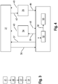
- the representation in Fig. 1 shows a schematic representation of a cutting unit 1.
- the cutting unit 1 has a main frame 2, on which a center portion 3 and at least two adjacent to the center portion 3 arranged side portions 4 are arranged.
- a knife bar 6 is arranged on the front side of the cutting mechanism 1 opposite the base frame 2 and extends essentially over the entire width of the cutting mechanism 1.
- reels (not shown) are arranged, extending over the width of a side portion 4 and partially over the Width of the center section 3 extend. The reels serve to improve the acceptance of the crop by the cutter bar. 6
- the separated from the cutter bar 6 crop is fed to a arranged behind the cutter bar 6 conveyor 5, which is carried out on the respective side sections 4 as at least one endless circulating belt 7, which rotates parallel to the longitudinal axis of the cutting unit 1.
- the endlessly circulating belts 7 are arranged adjacent to the center section 3 in order to transport the crop cut off by the cutter bar 6 parallel to the longitudinal axis of the cutting mechanism 1 in the direction of the center section 3 and to feed it to a feed device 8.
- the center section 3 likewise comprises a conveying device 5 designed as an endlessly circulating conveyor belt 7a. Other embodiments of the conveying device 5 in the center section 3 are conceivable.
- the intake device 8 is designed as a drivable feed roller 9.
- the collection device 8 leads the crop of the endless belts 7 to the center section 3 laterally provided for in the main frame 2, located behind the feed roller 9 opening through which the crop by a not shown on a combine harvester intake channel 10 to which the cutting unit 1 is detachably attached, the combine harvester is supplied for further processing.
- FIG. 2 shows a partial view of the cutting mechanism according to Fig. 1 ,
- support arms 11 are pivotally articulated about a horizontal axis.
- On the support arms 11 of the cutter bar 6 is arranged.
- Each support arm 11 is associated with a designed as a hydraulic cylinder 12 actuators, with which the respective support arm 11 and with these the cutter bar 6 in at least a first operating mode and a second operating mode are operable.
- the first operating mode the cutter bar 6 is rigidly operated.
- the hydraulic cylinders 12 are acted upon with a hydraulic pressure above a first limit, that the individual support arms 11 and with these the cutter bar 6 can perform no pivotal movement in the vertical direction.
- the cutting unit 1 is at a predetermined distance to Ground led. For controlling or regulating the distance or the cutting height, the distance between the cutting mechanism 1 and the ground is detected by a first sensor arrangement 13.
- the cutter bar 6 is operated flexibly.
- the hydraulic cylinders 12 are subjected to such a hydraulic pressure below a second limit that the cutter bar 6 rests on the ground with a dependent on the pressurization weight force.
- the support arms 11 undergo a vertical deflection. The vertical deflection is determined by means of a second sensor arrangement 17.
- a third mode of operation provides the flexible operation of the cutter bar 6 and the conveyor bar 5 of the side sections 4 arranged downstream of the cutter bar 6.
- the cutter bar 6 and the endlessly circulating belts 7 follow the changes in the ground contour, which are detected by the second sensor arrangement 17.
- the first sensor arrangement 13 is designed as a ground-scanning device. These are Tastbügel 14, Tastkufen or the like, which are each arranged with one end at a bearing point 15 on at least two support arms 11 of the cutting unit 1 about a horizontal pivot axis 16 pivotally. Each side section 4 preferably has at least two feeler bars 14 spaced apart from one another. The free end of the respective Tastbügels 14 rests on the ground. In a change in the bottom contour, which leads to a change in distance, the deflection of the respective Tastbügels 14 is detected about its pivot axis 16 by means of a potentiometer associated therewith.
- the signal provided by the respective potentiometer is evaluated by a control device 50 assigned to the cutting mechanism 1 in order to carry out a correction corresponding to the change in distance so that the predetermined height setting or cutting height is maintained.
- the Control device 50 is connected by means of a signal line 51 to the sensor arrangements 13 and 17, respectively.
- the Tastbügel 14 are detachably arranged on the support arms 11 in order to replace them if necessary.
- the second sensor arrangement 17 is arranged to detect the pivoting movement, which is caused by the cutter bars 6 supporting support arms 11 of the cutting unit 1 when the cutting unit 1 is operated in the second operating mode.
- the second sensor arrangement 17 comprises a shaft 18 which extends substantially over the entire width of the respective side section 4.
- the shaft 18 is rotatably mounted in brackets 19 which are associated with each support arm 11.
- a lever arrangement 20 is provided, through which the shaft 18 is connected to the respective support arm 11.
- the lever assembly 20 serves to transmit the deflection of the support arm 11 in the vertical direction on the shaft 18. By the lever assembly 20, the deflection of the support arm 11 is transmitted in a vertical direction to the shaft 18 as a rotational movement in a change in position of the support arm 11.
- the largest vertical deflection of a support arm 11 on a side portion 4 results in the strongest rotation of the shaft 18, which is used as a signal for automatic height adjustment of the cutting unit 1 for evaluation.
- the cutting unit 1, which is arranged on the intake duct 10 of the combine harvester be adjusted in height by corresponding arranged on the intake duct 10 and the combine hydraulic cylinder, that the distance of the main frame 2 with respect to the bottom at all side portions 4 is almost equal.
- the cutting unit 1 should be operated in such a way that when switching between the at least two operating modes depending on the selected operating mode, the first sensor arrangement 13 or the second sensor arrangement 17 is activated without interruption to carry out a distance determination.
- the calibration of the first sensor arrangement 13 and the second sensor arrangement 17 is required the calibration obtained data are stored in the control device 50 retrievable.
- a flowchart is shown for illustrating a calibration process or learning process, in which the first and the second sensor arrangement 13, 17 are calibrated within the calibration process.
- the calibration process is carried out regardless of the selected operating mode.
- it is checked in step 21 whether the first sensor arrangement 13 is arranged on the cutting unit 1. Irrespective of the presence of the first sensor arrangement 13, in step 22 the actuator system designed as a hydraulic cylinder 12 is automatically actuated by the control device 50 in order to relax the cutter bar 6.
- the determined calibration data are stored in the control device 50 retrievable. With the provision of the calibration data for the two sensor arrangements 13 and 17, an operating mode change can be performed at any time without having to carry out a calibration process again.
- the following describes by way of example how, after a single calibration, an operating mode change is carried out in the harvesting operation of the cutting unit 1.
- the first mode of operation which embodies the operation of the cutting unit 1 with rigidly operated cutter bar 6, which comes into play when harvesting stalky crop, such as grain.
- An operator specifies a cutting height in the context of this mode of operation. Compliance with the cutting height is controlled or regulated by means of the distance changes to the ground determined by means of the first sensor arrangement 13.
- the second sensor arrangement 17 is deactivated, that is, a processing of signals detected by the second sensor arrangement 17 by the control device 50 does not take place.
- the preset cutting height of the first mode of operation does not enable the harvesting of this part stock.
- the uninterrupted change from the first operating mode to the second operating mode allows a change in the operating behavior of the cutting mechanism 1 in such a way that the cutter bar 6 is operated flexibly.
- the feeler bars 14 are regulated to a minimum desired value.
- the cutter bar 6 by appropriate control of the actuators, that is, the hydraulic cylinder 12, relaxed.
- the first sensor arrangement 13 is deactivated by the control device 50, that is to say a processing of signals detected by the first sensor arrangement 13 by the control device 50 not anymore.
- the second sensor arrangement 17 is activated, that is to say signals provided by the latter, which represent a change in distance due to deflection of the cutter bar 6, are processed by the control device 50 for height adjustment.
- a change from the first operating mode to the second operating mode is also useful if harvesting with a rigidly operated cutter bar 6 over the entire working width of the cutting unit 1 is not possible due to the soil condition or the ground contour.
- the operator When leaving the area with stock of crop, the operator changes the operating mode again. By returning the set point for the feeler bar 14 back to the originally set cutting height, the uninterrupted transition from the use of the second sensor arrangement 17 back to the first sensor arrangement 13 is initiated. At the same time, the cutter bar 6 is again tensioned by actuation of the actuators, that is pressurizing the hydraulic cylinders 12, in order to be able to operate them rigidly.
- Another aspect of the method according to the invention is that when operating in the second operating mode or third operating mode when reaching a height position of the cutting unit 1 above a working position, such as at the headland or by manual lifting of the cutting unit 1, the control device 50, the actuator automatically in the way controls that the cutter bar 6 is rigidly operated. This ensures an optimal or minimal distance between reel and cutting table and allows the reel to optimally support the crop flow. This function also assists in reinserting the intent in the stock, since the cutter bar 6 is relaxed by the control of the actuator 50 by the control device 50 just before the ground, that is again operated flexibly, which is detected by the first sensor assembly 13. As a result, for example, the ⁇ hrenheber be dropped at the right angle to the ground, instead of jeopardizing it at a steep angle, which would set in an instant relaxation of the cutter bar 6, when reinserting.
- FIG. 3 is a flow chart illustrating possible operating states and transitions between them.
- a state of the cutter 1 is referred to as an initial state, in which the cutter bar 6 is rigidly operated.
- the cutting unit 1 is operated in the first operating mode. Compliance with the cutting height and the distance of the cutting unit 1 to the ground is monitored by means of the Tastbügel 14 of the first sensor assembly 13.
- the actuator system is controlled by the control device 50 in such a way that the hydraulic cylinders 12 are acted upon by a hydraulic pressure below the second limit value.
- the compliance of the cutting height by means of the first Sensor assembly 13 controlled certain distance changes to the ground or regulated.
- transition step 37 designates a transition step from state 32 to state 31, which is initiated as a function of the setpoint value of the cutting height control or alternatively by the lifting of the cutting unit 1 beyond the working position.
- the transition step 37 from the second operating mode to the first operating mode thus takes place by changing the setpoint value of the cutting height control from a minimum desired value to the setpoint value of the cutting height set for the first operating mode or manually lifting the cutting unit 1.
- the actual value of the hydraulic pressure is monitored by the control device 50, with which the hydraulic cylinders 12 of the support arms 11 are acted upon.
- the control device 50 deactivates the first sensor arrangement 13 and activates the second sensor arrangement 17.
- the state of the cutting unit 1 is designated, in which the cutting unit 1 is operated in a further operating mode.
- the cutting unit 1 is manually by an intervention of a Operator raised. This operating mode can come into effect when a headland has been reached.
- state 39 denotes a transition step from state 33 to state 34, which is initiated with the lifting of the cutting mechanism 1.
- the control device 50 monitors the exceeding of a threshold value of the actual value of the cutting height.
- a further, time-dependent threshold value is monitored by the control device 50.
- the control device 50 monitors the duration of the exceeding of the threshold value for the cutting height.
- a transition step 40 is initiated by the control device 50.
- the cutting unit 1 is transferred to the first operating mode according to the state 31.
- the actuator is controlled by the control device 50 accordingly to operate the cutter bar 6 rigid.
- the automatic deactivation of the second sensor arrangement 17 and the activation of the first sensor arrangement 13 are performed by the control device 50.
- the transition step 40 is controlled in a position-dependent and time-dependent manner.
- transition step 41 denotes a transition step from state 34 back to state 33, which is initiated after a lifting of the cutting mechanism 1, when the duration of lifting of the cutting mechanism 1 does not exceed the time-dependent threshold value. During the transition step 41, no change in the operating mode has yet taken place.
- the cutting unit 1 With the state of the cutting unit 1 is designated, in which the cutting unit 1 is operated in a further operating mode. In this further mode of operation, the cutting unit 1 is lowered manually by an intervention of an operator.
- This operating mode can be after a drive through a headland come to fruition before the cutting unit 1 is used again in the stock to be harvested.
- transition step 42 denotes a transition step from state 31 to state 35, which is initiated with the manual lowering of the cutting mechanism 1. According to this transitional step 42, the undershooting of a threshold value of the actual value of the cutting height with simultaneous manual lowering of the cutting unit 1 is monitored by the control device 50.
- a further, time-dependent threshold value is monitored by the control device 50.
- the control device 50 monitors the duration of the undershooting of the threshold value for the cutting height. If this time-dependent threshold value is also undershot, a transition step 44 is initiated by the control device 50.
- the cutting unit 1 is transferred from the first operating mode according to the state 31 in the second operating mode according to the state 33.
- the actuator is controlled by the control device 50 accordingly to operate the cutter bar 6 flexible.
- the automatic deactivation of the first sensor arrangement 13 and the activation of the second sensor arrangement 17 are effected by the control device 50.
- the transition step 44 is likewise controlled in a position-dependent and time-dependent manner.
- transition step 43 denotes a transition step from state 35 back to state 31, which is initiated after a lowering of the cutting mechanism 1, if the duration of lowering of the cutting mechanism 1 does not exceed the time-dependent threshold value. During the transition step 43, no change in the operating mode has yet taken place.
- this method is also applicable if the lifting and lowering of the cutting unit 1 is carried out automatically. Reaching and leaving, for example, a headland can by means of a position location system be determined so that the change between the operating modes can be automated.
Applications Claiming Priority (1)
| Application Number | Priority Date | Filing Date | Title |
|---|---|---|---|
| DE102016124552.6A DE102016124552A1 (de) | 2016-12-15 | 2016-12-15 | Verfahren zum Betreiben eines Schneidwerks |
Publications (2)
| Publication Number | Publication Date |
|---|---|
| EP3335541A1 true EP3335541A1 (fr) | 2018-06-20 |
| EP3335541B1 EP3335541B1 (fr) | 2020-02-19 |
Family
ID=59631663
Family Applications (1)
| Application Number | Title | Priority Date | Filing Date |
|---|---|---|---|
| EP17186410.1A Active EP3335541B1 (fr) | 2016-12-15 | 2017-08-16 | Procédé de fonctionnement d'une barre de coupe |
Country Status (6)
| Country | Link |
|---|---|
| US (2) | US10736265B2 (fr) |
| EP (1) | EP3335541B1 (fr) |
| CN (1) | CN108207291B (fr) |
| DE (1) | DE102016124552A1 (fr) |
| HU (1) | HUE049798T2 (fr) |
| RU (1) | RU2756181C2 (fr) |
Cited By (2)
| Publication number | Priority date | Publication date | Assignee | Title |
|---|---|---|---|---|
| WO2021053099A1 (fr) | 2019-09-19 | 2021-03-25 | Carl Geringhoff Gmbh & Co. Kg | Unité de coupe comportant des capteurs pour la régulation de la hauteur |
| EP4282247A1 (fr) * | 2022-05-25 | 2023-11-29 | CNH Industrial America LLC | Séquence de capture de grain de tournière pour tête de véhicule agricole |
Families Citing this family (7)
| Publication number | Priority date | Publication date | Assignee | Title |
|---|---|---|---|---|
| US10959374B2 (en) * | 2017-12-08 | 2021-03-30 | Agco Corporation | Flexible header with sectional height adjustment |
| DE102018107804A1 (de) * | 2018-04-03 | 2019-10-10 | Claas Selbstfahrende Erntemaschinen Gmbh | Höhensteuerungssystem für ein Erntevorsatzgerät |
| US20220015292A1 (en) * | 2018-11-16 | 2022-01-20 | Cnh Industrial America Llc | Airbag system for a harvester header |
| US20220053752A1 (en) | 2018-12-19 | 2022-02-24 | Bayer Aktiengesellschaft | Control of plants |
| US20210037709A1 (en) * | 2019-08-05 | 2021-02-11 | Cnh Industrial America Llc | Electrical Cut Quality System for Harvesters |
| US11483968B2 (en) * | 2019-08-05 | 2022-11-01 | Firefly Automatix, Inc. | Dynamically adjusting the cutting height of a mower deck based on a mower's location |
| US11737390B2 (en) * | 2021-02-23 | 2023-08-29 | Cnh Industrial America Llc | Harvesting header multi-sensor height control |
Citations (4)
| Publication number | Priority date | Publication date | Assignee | Title |
|---|---|---|---|---|
| US5359836A (en) * | 1993-02-01 | 1994-11-01 | Control Concepts, Inc. | Agricultural harvester with closed loop header control |
| US7975458B1 (en) * | 2010-08-23 | 2011-07-12 | Cnh America Llc | Control system for a crop harvesting header |
| EP2832206A1 (fr) * | 2013-07-31 | 2015-02-04 | CNH Industrial Belgium nv | Commande d'inclinaison latérale d'en-tête à fonctionnement automatique en modes d'inclinaison contrôlée et flotteur libre |
| EP3087819A2 (fr) * | 2015-05-01 | 2016-11-02 | Deere & Company | Circuit de commande de la hauteur d'une tête de récolte |
Family Cites Families (11)
| Publication number | Priority date | Publication date | Assignee | Title |
|---|---|---|---|---|
| US20080276590A1 (en) * | 2006-02-10 | 2008-11-13 | Agco Corporation | Flexible draper and cutter bar with tilt arm for cutterbar drive |
| US7520115B2 (en) * | 2006-09-15 | 2009-04-21 | Deere & Company | Header float arm load compensation |
| US7707811B1 (en) * | 2009-04-15 | 2010-05-04 | Cnh America Llc | Header flotation and lift system with dual mode operation for a plant cutting machine |
| US7866136B1 (en) * | 2009-09-22 | 2011-01-11 | Cnh America Llc | Belt pickup for a draper header |
| US8201388B1 (en) * | 2011-05-02 | 2012-06-19 | Deere & Company | Sensor for a header height control system |
| CA2900987C (fr) * | 2013-02-12 | 2021-01-19 | Headsight, Inc. | Systeme d'etalonnage automatique pour dispositif de commande de la hauteur d'un collecteur avec retour d'information a l'operateur |
| US9807933B2 (en) * | 2014-10-20 | 2017-11-07 | Cnh Industrial America Llc | Sensor equipped agricultural harvester |
| US9402343B1 (en) * | 2015-04-23 | 2016-08-02 | Jose Luis Allochis | Flexible cutterbar assembly for a harvesting platform |
| US10517207B2 (en) * | 2016-05-02 | 2019-12-31 | Cnh Industrial America Llc | Programmable one-touch raise feature for an agricultural harvester such as a windrower |
| US10575462B2 (en) * | 2016-10-14 | 2020-03-03 | Deere & Company | Sickle bar drive mount |
| US10349578B2 (en) * | 2017-02-16 | 2019-07-16 | Cnh Industrial America Llc | Combination flex and rigid header height control in a harvester |
-
2016
- 2016-12-15 DE DE102016124552.6A patent/DE102016124552A1/de not_active Withdrawn
-
2017
- 2017-08-16 EP EP17186410.1A patent/EP3335541B1/fr active Active
- 2017-08-16 HU HUE17186410A patent/HUE049798T2/hu unknown
- 2017-12-11 RU RU2017143210A patent/RU2756181C2/ru active
- 2017-12-14 US US15/842,316 patent/US10736265B2/en active Active
- 2017-12-15 CN CN201711348089.0A patent/CN108207291B/zh active Active
-
2020
- 2020-08-10 US US16/989,629 patent/US11825767B2/en active Active
Patent Citations (4)
| Publication number | Priority date | Publication date | Assignee | Title |
|---|---|---|---|---|
| US5359836A (en) * | 1993-02-01 | 1994-11-01 | Control Concepts, Inc. | Agricultural harvester with closed loop header control |
| US7975458B1 (en) * | 2010-08-23 | 2011-07-12 | Cnh America Llc | Control system for a crop harvesting header |
| EP2832206A1 (fr) * | 2013-07-31 | 2015-02-04 | CNH Industrial Belgium nv | Commande d'inclinaison latérale d'en-tête à fonctionnement automatique en modes d'inclinaison contrôlée et flotteur libre |
| EP3087819A2 (fr) * | 2015-05-01 | 2016-11-02 | Deere & Company | Circuit de commande de la hauteur d'une tête de récolte |
Cited By (2)
| Publication number | Priority date | Publication date | Assignee | Title |
|---|---|---|---|---|
| WO2021053099A1 (fr) | 2019-09-19 | 2021-03-25 | Carl Geringhoff Gmbh & Co. Kg | Unité de coupe comportant des capteurs pour la régulation de la hauteur |
| EP4282247A1 (fr) * | 2022-05-25 | 2023-11-29 | CNH Industrial America LLC | Séquence de capture de grain de tournière pour tête de véhicule agricole |
Also Published As
| Publication number | Publication date |
|---|---|
| RU2017143210A3 (fr) | 2021-03-30 |
| RU2756181C2 (ru) | 2021-09-28 |
| RU2017143210A (ru) | 2019-06-11 |
| US10736265B2 (en) | 2020-08-11 |
| HUE049798T2 (hu) | 2020-10-28 |
| DE102016124552A1 (de) | 2018-06-21 |
| CN108207291A (zh) | 2018-06-29 |
| US20200367432A1 (en) | 2020-11-26 |
| US20180168101A1 (en) | 2018-06-21 |
| US11825767B2 (en) | 2023-11-28 |
| CN108207291B (zh) | 2022-08-02 |
| EP3335541B1 (fr) | 2020-02-19 |
Similar Documents
| Publication | Publication Date | Title |
|---|---|---|
| EP3335541B1 (fr) | Procédé de fonctionnement d'une barre de coupe | |
| EP3549433B1 (fr) | Système de commande de hauteur pour un appareil tête de récolte | |
| DE602004003419T2 (de) | Schneidtrommelverstellsystem | |
| EP3560314A1 (fr) | Mécanisme de coupe à réglage automatique de l'orientation de dent de rabatteur | |
| DE602004004307T2 (de) | Vorrichtung zur Höheneinstellung eines Spindelmähers | |
| EP3593620A1 (fr) | Système de récolte | |
| DE602004003420T2 (de) | Verfahren und Vorrichtung zum Einstellen und zur Aufrechterhaltung des Abstands zwischen Trommel und Gegenschneide | |
| EP3403485A1 (fr) | Dispositif d'auto-apprentissage, prenant en considération les entrées de correction destiné au contrôle automatique d'un paramètre de travail d'un dispositif de transport de produit de la récolte et/ou de traitement | |
| EP1790210B1 (fr) | Dispositif d'alimentation pour une faucheuse-hâcheuse | |
| EP3300580A1 (fr) | Moissonneuse-batteuse pourvue de barre de coupe et dispositif de commande d'une barre de coupe | |
| EP2837280A1 (fr) | Moissonneuse-batteuse équipée d'un dispositif de hache-paille | |
| EP2863729B1 (fr) | Mécanisme de coupe | |
| EP2732689A1 (fr) | Barre de coupe | |
| EP3494771A1 (fr) | Dispositif de hauteur de coupe automatique | |
| EP3598886B1 (fr) | Engin d'abattage-façonnage automoteur | |
| EP3989705A1 (fr) | Outil de coupe destiné à une moissonneuse-batteuse | |
| EP4056021B1 (fr) | Barre de coupe | |
| DE102019125282A1 (de) | Schneidwerk mit höhenelastisch gelagerten Schneidelementen | |
| EP3628142B1 (fr) | Dispositif de coupe pour un engin d'abattage-façonnage agricole ainsi que procédé de fonctionnement d'un dispositif de coupe | |
| EP1813143B1 (fr) | Unité de signalisation d'informations d'état spécifiques à l'entraînement sur un véhicule à moteur utilitaire agricole | |
| AT525960B1 (de) | Vorrichtung zur adaptiven Höhenverstellung eines Sammelschilds an einem Stachelwalzenaufnehmer einer Kürbiserntemaschine | |
| EP3243372A1 (fr) | Procédé de réglage d'un angle de coupe d'un outil avant disposé sur une moissonneuse automobile | |
| EP3967127A1 (fr) | Récolteuse-hacheuse-chargeuse de fourrage automotrice | |
| EP4248730A2 (fr) | Appareil adaptable, procédé de commande d'un appareil accessoire ainsi que moissonneuse-batteuse | |
| EP4252519A1 (fr) | Moissonneuse agricole et procédé de commande d'une moissonneuse agricole |
Legal Events
| Date | Code | Title | Description |
|---|---|---|---|
| PUAI | Public reference made under article 153(3) epc to a published international application that has entered the european phase |
Free format text: ORIGINAL CODE: 0009012 |
|
| STAA | Information on the status of an ep patent application or granted ep patent |
Free format text: STATUS: THE APPLICATION HAS BEEN PUBLISHED |
|
| AK | Designated contracting states |
Kind code of ref document: A1 Designated state(s): AL AT BE BG CH CY CZ DE DK EE ES FI FR GB GR HR HU IE IS IT LI LT LU LV MC MK MT NL NO PL PT RO RS SE SI SK SM TR |
|
| AX | Request for extension of the european patent |
Extension state: BA ME |
|
| STAA | Information on the status of an ep patent application or granted ep patent |
Free format text: STATUS: REQUEST FOR EXAMINATION WAS MADE |
|
| 17P | Request for examination filed |
Effective date: 20181220 |
|
| RBV | Designated contracting states (corrected) |
Designated state(s): AL AT BE BG CH CY CZ DE DK EE ES FI FR GB GR HR HU IE IS IT LI LT LU LV MC MK MT NL NO PL PT RO RS SE SI SK SM TR |
|
| GRAP | Despatch of communication of intention to grant a patent |
Free format text: ORIGINAL CODE: EPIDOSNIGR1 |
|
| STAA | Information on the status of an ep patent application or granted ep patent |
Free format text: STATUS: GRANT OF PATENT IS INTENDED |
|
| INTG | Intention to grant announced |
Effective date: 20191106 |
|
| GRAS | Grant fee paid |
Free format text: ORIGINAL CODE: EPIDOSNIGR3 |
|
| GRAA | (expected) grant |
Free format text: ORIGINAL CODE: 0009210 |
|
| STAA | Information on the status of an ep patent application or granted ep patent |
Free format text: STATUS: THE PATENT HAS BEEN GRANTED |
|
| AK | Designated contracting states |
Kind code of ref document: B1 Designated state(s): AL AT BE BG CH CY CZ DE DK EE ES FI FR GB GR HR HU IE IS IT LI LT LU LV MC MK MT NL NO PL PT RO RS SE SI SK SM TR |
|
| REG | Reference to a national code |
Ref country code: CH Ref legal event code: EP |
|
| REG | Reference to a national code |
Ref country code: DE Ref legal event code: R096 Ref document number: 502017003841 Country of ref document: DE |
|
| REG | Reference to a national code |
Ref country code: AT Ref legal event code: REF Ref document number: 1233892 Country of ref document: AT Kind code of ref document: T Effective date: 20200315 |
|
| REG | Reference to a national code |
Ref country code: IE Ref legal event code: FG4D Free format text: LANGUAGE OF EP DOCUMENT: GERMAN |
|
| REG | Reference to a national code |
Ref country code: NL Ref legal event code: MP Effective date: 20200219 |
|
| PG25 | Lapsed in a contracting state [announced via postgrant information from national office to epo] |
Ref country code: RS Free format text: LAPSE BECAUSE OF FAILURE TO SUBMIT A TRANSLATION OF THE DESCRIPTION OR TO PAY THE FEE WITHIN THE PRESCRIBED TIME-LIMIT Effective date: 20200219 Ref country code: NO Free format text: LAPSE BECAUSE OF FAILURE TO SUBMIT A TRANSLATION OF THE DESCRIPTION OR TO PAY THE FEE WITHIN THE PRESCRIBED TIME-LIMIT Effective date: 20200519 Ref country code: FI Free format text: LAPSE BECAUSE OF FAILURE TO SUBMIT A TRANSLATION OF THE DESCRIPTION OR TO PAY THE FEE WITHIN THE PRESCRIBED TIME-LIMIT Effective date: 20200219 |
|
| REG | Reference to a national code |
Ref country code: LT Ref legal event code: MG4D |
|
| PG25 | Lapsed in a contracting state [announced via postgrant information from national office to epo] |
Ref country code: HR Free format text: LAPSE BECAUSE OF FAILURE TO SUBMIT A TRANSLATION OF THE DESCRIPTION OR TO PAY THE FEE WITHIN THE PRESCRIBED TIME-LIMIT Effective date: 20200219 Ref country code: BG Free format text: LAPSE BECAUSE OF FAILURE TO SUBMIT A TRANSLATION OF THE DESCRIPTION OR TO PAY THE FEE WITHIN THE PRESCRIBED TIME-LIMIT Effective date: 20200519 Ref country code: LV Free format text: LAPSE BECAUSE OF FAILURE TO SUBMIT A TRANSLATION OF THE DESCRIPTION OR TO PAY THE FEE WITHIN THE PRESCRIBED TIME-LIMIT Effective date: 20200219 Ref country code: SE Free format text: LAPSE BECAUSE OF FAILURE TO SUBMIT A TRANSLATION OF THE DESCRIPTION OR TO PAY THE FEE WITHIN THE PRESCRIBED TIME-LIMIT Effective date: 20200219 Ref country code: IS Free format text: LAPSE BECAUSE OF FAILURE TO SUBMIT A TRANSLATION OF THE DESCRIPTION OR TO PAY THE FEE WITHIN THE PRESCRIBED TIME-LIMIT Effective date: 20200619 Ref country code: GR Free format text: LAPSE BECAUSE OF FAILURE TO SUBMIT A TRANSLATION OF THE DESCRIPTION OR TO PAY THE FEE WITHIN THE PRESCRIBED TIME-LIMIT Effective date: 20200520 |
|
| PG25 | Lapsed in a contracting state [announced via postgrant information from national office to epo] |
Ref country code: NL Free format text: LAPSE BECAUSE OF FAILURE TO SUBMIT A TRANSLATION OF THE DESCRIPTION OR TO PAY THE FEE WITHIN THE PRESCRIBED TIME-LIMIT Effective date: 20200219 |
|
| REG | Reference to a national code |
Ref country code: HU Ref legal event code: AG4A Ref document number: E049798 Country of ref document: HU |
|
| PG25 | Lapsed in a contracting state [announced via postgrant information from national office to epo] |
Ref country code: RO Free format text: LAPSE BECAUSE OF FAILURE TO SUBMIT A TRANSLATION OF THE DESCRIPTION OR TO PAY THE FEE WITHIN THE PRESCRIBED TIME-LIMIT Effective date: 20200219 Ref country code: SK Free format text: LAPSE BECAUSE OF FAILURE TO SUBMIT A TRANSLATION OF THE DESCRIPTION OR TO PAY THE FEE WITHIN THE PRESCRIBED TIME-LIMIT Effective date: 20200219 Ref country code: PT Free format text: LAPSE BECAUSE OF FAILURE TO SUBMIT A TRANSLATION OF THE DESCRIPTION OR TO PAY THE FEE WITHIN THE PRESCRIBED TIME-LIMIT Effective date: 20200712 Ref country code: CZ Free format text: LAPSE BECAUSE OF FAILURE TO SUBMIT A TRANSLATION OF THE DESCRIPTION OR TO PAY THE FEE WITHIN THE PRESCRIBED TIME-LIMIT Effective date: 20200219 Ref country code: DK Free format text: LAPSE BECAUSE OF FAILURE TO SUBMIT A TRANSLATION OF THE DESCRIPTION OR TO PAY THE FEE WITHIN THE PRESCRIBED TIME-LIMIT Effective date: 20200219 Ref country code: LT Free format text: LAPSE BECAUSE OF FAILURE TO SUBMIT A TRANSLATION OF THE DESCRIPTION OR TO PAY THE FEE WITHIN THE PRESCRIBED TIME-LIMIT Effective date: 20200219 Ref country code: ES Free format text: LAPSE BECAUSE OF FAILURE TO SUBMIT A TRANSLATION OF THE DESCRIPTION OR TO PAY THE FEE WITHIN THE PRESCRIBED TIME-LIMIT Effective date: 20200219 Ref country code: SM Free format text: LAPSE BECAUSE OF FAILURE TO SUBMIT A TRANSLATION OF THE DESCRIPTION OR TO PAY THE FEE WITHIN THE PRESCRIBED TIME-LIMIT Effective date: 20200219 Ref country code: EE Free format text: LAPSE BECAUSE OF FAILURE TO SUBMIT A TRANSLATION OF THE DESCRIPTION OR TO PAY THE FEE WITHIN THE PRESCRIBED TIME-LIMIT Effective date: 20200219 |
|
| REG | Reference to a national code |
Ref country code: DE Ref legal event code: R097 Ref document number: 502017003841 Country of ref document: DE |
|
| PLBE | No opposition filed within time limit |
Free format text: ORIGINAL CODE: 0009261 |
|
| STAA | Information on the status of an ep patent application or granted ep patent |
Free format text: STATUS: NO OPPOSITION FILED WITHIN TIME LIMIT |
|
| 26N | No opposition filed |
Effective date: 20201120 |
|
| PG25 | Lapsed in a contracting state [announced via postgrant information from national office to epo] |
Ref country code: IT Free format text: LAPSE BECAUSE OF FAILURE TO SUBMIT A TRANSLATION OF THE DESCRIPTION OR TO PAY THE FEE WITHIN THE PRESCRIBED TIME-LIMIT Effective date: 20200219 |
|
| PG25 | Lapsed in a contracting state [announced via postgrant information from national office to epo] |
Ref country code: PL Free format text: LAPSE BECAUSE OF FAILURE TO SUBMIT A TRANSLATION OF THE DESCRIPTION OR TO PAY THE FEE WITHIN THE PRESCRIBED TIME-LIMIT Effective date: 20200219 Ref country code: SI Free format text: LAPSE BECAUSE OF FAILURE TO SUBMIT A TRANSLATION OF THE DESCRIPTION OR TO PAY THE FEE WITHIN THE PRESCRIBED TIME-LIMIT Effective date: 20200219 |
|
| PG25 | Lapsed in a contracting state [announced via postgrant information from national office to epo] |
Ref country code: MC Free format text: LAPSE BECAUSE OF FAILURE TO SUBMIT A TRANSLATION OF THE DESCRIPTION OR TO PAY THE FEE WITHIN THE PRESCRIBED TIME-LIMIT Effective date: 20200219 |
|
| REG | Reference to a national code |
Ref country code: CH Ref legal event code: PL |
|
| PG25 | Lapsed in a contracting state [announced via postgrant information from national office to epo] |
Ref country code: CH Free format text: LAPSE BECAUSE OF NON-PAYMENT OF DUE FEES Effective date: 20200831 Ref country code: LU Free format text: LAPSE BECAUSE OF NON-PAYMENT OF DUE FEES Effective date: 20200816 Ref country code: LI Free format text: LAPSE BECAUSE OF NON-PAYMENT OF DUE FEES Effective date: 20200831 |
|
| PG25 | Lapsed in a contracting state [announced via postgrant information from national office to epo] |
Ref country code: FR Free format text: LAPSE BECAUSE OF NON-PAYMENT OF DUE FEES Effective date: 20200831 |
|
| PG25 | Lapsed in a contracting state [announced via postgrant information from national office to epo] |
Ref country code: IE Free format text: LAPSE BECAUSE OF NON-PAYMENT OF DUE FEES Effective date: 20200816 |
|
| GBPC | Gb: european patent ceased through non-payment of renewal fee |
Effective date: 20210816 |
|
| PG25 | Lapsed in a contracting state [announced via postgrant information from national office to epo] |
Ref country code: TR Free format text: LAPSE BECAUSE OF FAILURE TO SUBMIT A TRANSLATION OF THE DESCRIPTION OR TO PAY THE FEE WITHIN THE PRESCRIBED TIME-LIMIT Effective date: 20200219 Ref country code: MT Free format text: LAPSE BECAUSE OF FAILURE TO SUBMIT A TRANSLATION OF THE DESCRIPTION OR TO PAY THE FEE WITHIN THE PRESCRIBED TIME-LIMIT Effective date: 20200219 Ref country code: CY Free format text: LAPSE BECAUSE OF FAILURE TO SUBMIT A TRANSLATION OF THE DESCRIPTION OR TO PAY THE FEE WITHIN THE PRESCRIBED TIME-LIMIT Effective date: 20200219 |
|
| PG25 | Lapsed in a contracting state [announced via postgrant information from national office to epo] |
Ref country code: MK Free format text: LAPSE BECAUSE OF FAILURE TO SUBMIT A TRANSLATION OF THE DESCRIPTION OR TO PAY THE FEE WITHIN THE PRESCRIBED TIME-LIMIT Effective date: 20200219 Ref country code: AL Free format text: LAPSE BECAUSE OF FAILURE TO SUBMIT A TRANSLATION OF THE DESCRIPTION OR TO PAY THE FEE WITHIN THE PRESCRIBED TIME-LIMIT Effective date: 20200219 |
|
| PG25 | Lapsed in a contracting state [announced via postgrant information from national office to epo] |
Ref country code: GB Free format text: LAPSE BECAUSE OF NON-PAYMENT OF DUE FEES Effective date: 20210816 |
|
| P01 | Opt-out of the competence of the unified patent court (upc) registered |
Effective date: 20230516 |
|
| REG | Reference to a national code |
Ref country code: AT Ref legal event code: MM01 Ref document number: 1233892 Country of ref document: AT Kind code of ref document: T Effective date: 20220816 |
|
| PG25 | Lapsed in a contracting state [announced via postgrant information from national office to epo] |
Ref country code: AT Free format text: LAPSE BECAUSE OF NON-PAYMENT OF DUE FEES Effective date: 20220816 |
|
| PGFP | Annual fee paid to national office [announced via postgrant information from national office to epo] |
Ref country code: HU Payment date: 20230823 Year of fee payment: 7 Ref country code: DE Payment date: 20230821 Year of fee payment: 7 Ref country code: BE Payment date: 20230821 Year of fee payment: 7 |