EP3335419B1 - Dispositif de caméra de véhicule pour enregistrer un environnement d'un véhicule automobile ainsi que dispositif d'assistance à la conduite pour reconnaissance d'objet avec un tel dispositif de caméra de véhicule - Google Patents
Dispositif de caméra de véhicule pour enregistrer un environnement d'un véhicule automobile ainsi que dispositif d'assistance à la conduite pour reconnaissance d'objet avec un tel dispositif de caméra de véhicule Download PDFInfo
- Publication number
- EP3335419B1 EP3335419B1 EP16745040.2A EP16745040A EP3335419B1 EP 3335419 B1 EP3335419 B1 EP 3335419B1 EP 16745040 A EP16745040 A EP 16745040A EP 3335419 B1 EP3335419 B1 EP 3335419B1
- Authority
- EP
- European Patent Office
- Prior art keywords
- optronics
- unit
- vehicle camera
- recorded
- area
- Prior art date
- Legal status (The legal status is an assumption and is not a legal conclusion. Google has not performed a legal analysis and makes no representation as to the accuracy of the status listed.)
- Active
Links
- 230000003287 optical effect Effects 0.000 claims description 9
- 230000002093 peripheral effect Effects 0.000 claims description 5
- 238000001514 detection method Methods 0.000 description 92
- 238000011156 evaluation Methods 0.000 description 11
- 238000003384 imaging method Methods 0.000 description 8
- 238000012545 processing Methods 0.000 description 5
- 238000013461 design Methods 0.000 description 4
- 230000007704 transition Effects 0.000 description 4
- 230000007613 environmental effect Effects 0.000 description 3
- 230000004075 alteration Effects 0.000 description 1
- 230000007423 decrease Effects 0.000 description 1
- 230000001419 dependent effect Effects 0.000 description 1
- 238000011161 development Methods 0.000 description 1
- 230000000694 effects Effects 0.000 description 1
- 238000009434 installation Methods 0.000 description 1
- 230000010354 integration Effects 0.000 description 1
- 238000012806 monitoring device Methods 0.000 description 1
- 238000001454 recorded image Methods 0.000 description 1
- 239000007787 solid Substances 0.000 description 1
Images


Classifications
-
- H—ELECTRICITY
- H04—ELECTRIC COMMUNICATION TECHNIQUE
- H04N—PICTORIAL COMMUNICATION, e.g. TELEVISION
- H04N7/00—Television systems
- H04N7/18—Closed-circuit television [CCTV] systems, i.e. systems in which the video signal is not broadcast
- H04N7/181—Closed-circuit television [CCTV] systems, i.e. systems in which the video signal is not broadcast for receiving images from a plurality of remote sources
-
- G—PHYSICS
- G06—COMPUTING; CALCULATING OR COUNTING
- G06V—IMAGE OR VIDEO RECOGNITION OR UNDERSTANDING
- G06V20/00—Scenes; Scene-specific elements
- G06V20/50—Context or environment of the image
- G06V20/56—Context or environment of the image exterior to a vehicle by using sensors mounted on the vehicle
- G06V20/58—Recognition of moving objects or obstacles, e.g. vehicles or pedestrians; Recognition of traffic objects, e.g. traffic signs, traffic lights or roads
Definitions
- the present invention relates to a vehicle camera device for recording surroundings of a motor vehicle according to the preamble of claim 1.
- the invention also relates to a driver assistance device for object recognition with such a vehicle camera device.
- Driver assistance devices with one or more cameras are used to evaluate the surroundings of a motor vehicle, for example to evaluate lanes, traffic signs, traffic lights and other road users.
- the cameras are generally used for capturing images from the area of the motor vehicle ahead in the direction of travel. Such cameras typically have an opening angle of about 40 to 45 degrees.
- a surveillance device is known with cameras which each have a plurality of image sensors which are designed in such a way that they each have different areas of a scene variable object distance.
- the image sensors are each equipped with optics that provide the same resolution regardless of the object distance, and the image sensors that are intended for different object distances have objects with different fixed focal lengths.
- the pamphlet DE 20 2010 002 827 U1 describes a camera monitoring device for a rear driving space of a motor vehicle, with a housing in which two cameras are arranged for capturing images of the rear driving space.
- the cameras are aligned differently from one another, so that their respective detection areas at least partially overlap at least in the vertical direction.
- the second camera is tilted towards the ground in order to capture the close-up area of the rear driving space.
- the camera includes optics with non-uniform or non-uniform angular resolution in the camera's field of view.
- the optics are preferably designed in such a way that the angular resolution steadily decreases from the center of the field of view to the edge of the field of view.
- the pamphlet WO2015/062603A1 describes a driver assistance system with a camera with a horizontal picture angle and a vertical picture angle, a control and evaluation unit and a display.
- the camera has optics with a non-uniform angular resolution in the camera's field of view.
- the optics are preferably designed in such a way that an increased angular resolution is realized in a central area of the field of view located in the solid angle area around the optical axis.
- a vehicle vision system is known, with an image capturing device and a lens mounted in front of the image capturing device, which lens has at least a first and a second focal length, for imaging an object onto the image capturing device.
- the image capturing device and the lens are arranged relative to one another and designed in such a way that an image of an object on a first image capturing area of the image capturing device is based on the first focal length, and that an image on a second image capturing area of the image capturing device is based on the second focal length.
- the invention is based on the object of proposing an improved vehicle camera device which enables the surroundings of the motor vehicle to be recorded with the largest possible recording area and a sufficient angular resolution for object recognition.
- a vehicle camera device for recording surroundings of a motor vehicle.
- the environment is in particular the area in front of the motor vehicle.
- the vehicle camera device can preferably be integrated into or connected to a driver assistance device, with the driver assistance device being designed in particular for object recognition from the image data provided by the vehicle camera device.
- the Vehicle camera device is a camera to be arranged in the interior of the motor vehicle behind the windshield and directed in the direction of travel.
- the vehicle camera device includes a first and a second optronic unit.
- Optronics each have optics for projecting light and at least or precisely one image sensor for detecting the light projected by the optics.
- the optics of the first and second optronics are preferably designed with a fixed focal length.
- the first and second optronics are arranged together in a housing of the vehicle camera device. The integration of the two optronics in the housing of the vehicle camera device achieves a compact, space-saving design for installation in the motor vehicle.
- the first and the second optronic unit are preferably arranged directly next to one another in the same viewing direction, in particular next to one another or one above the other.
- Directly here means a distance running transversely to the viewing direction of, for example, at most ten centimeters, in particular at most five centimeters, in particular at most one centimeter.
- the optical axes of the first and second optronics particularly preferably run parallel to one another.
- the first optronic is designed to record a first detection area and the second optronic a second detection area of the environment.
- the image sensor and the optics of the respective optronics jointly specify a horizontal and a vertical angle of view, with the horizontal and vertical angle of view spanning the detection area.
- the vehicle camera device is designed in such a way that the first and the second detection area can be recorded independently of one another, processed and/or transmitted as independent image data to the driver assistance device for object recognition.
- the first and the second optronic have differently sized angles of view.
- the first and the second optronic unit have horizontal angles of view of different sizes on, so that the detection areas differ in particular in the horizontal direction.
- the first and second optronics have different vertical angles of view, so that the detection areas differ in the vertical direction.
- the differently sized image angles of the detection areas enable the detection of objects in different environmental areas of the motor vehicle with just one vehicle camera device.
- the detection areas recorded by the first and second optronics have an overlapping section.
- the overlapping section is therefore an overlapping area of the first and second detection area.
- the same surrounding area is imaged in the overlapping section recorded by the first and second optronics.
- the overlapping section of the first and second detection area is in each case an image section with the same image content.
- the overlapping sections recorded by the first and second optronics preferably have the same horizontal and/or vertical angle of view, alternatively or optionally in addition each have the same focal length.
- the first optronic is designed in such a way that the overlapping section recorded by the first optronic has a different angular resolution, according to the invention a reduced angular resolution, than in the remaining area of the first detection area.
- a different angular resolution is thus realized in the overlapping section compared to the rest of the first detection area detected by the first optronics.
- the image sensor has a lower resolution in the area recording the overlapping section than in the area recording the remaining area is trained. This configuration has the advantage that a structurally simple and therefore cost-effective optics with a constant angular resolution can be used.
- the image sensor has a homogeneous pixel/cm resolution and the optics are designed in such a way that a different angular resolution is realized in the overlapping section than in the remaining area of the first detection area.
- the changed, in particular reduced, angular resolution in the overlapping section achieves the advantage that the computing effort for processing the first detection area is limited to what is absolutely necessary.
- the recording of the remaining area of the first detection area in particular with an increased angular resolution, enables object recognition without additional image processing, e.g. B. a virtual pixel increase.
- the overlapping section has the advantage that the first and the second optronic unit can be designed with different recording priorities. For example, it is possible to design the first optronics with the largest possible detection area and thus also to detect peripheral areas, as may be necessary in the intersection area for the early detection of crossing road users or for the detection of traffic lights in the front row.
- the second optronic z. B. a detailed recording can be implemented in the overlapping section, so that recording objects both in the near range, for example in the distance range between one and 50 meters, as well as in the Far range, for example in the distance range between 50 and 500 meters are recognizable. Consequently, object recognition is achieved both in different distance and environmental areas of the motor vehicle with only one vehicle camera device.
- an angular resolution of at most 10 pixels per degree, in particular at most 5 pixels per degree is implemented in the overlapping section recorded by the first optronics.
- an angular resolution of at least 30 pixels per degree, in particular at least 40 pixels per degree is implemented in the remaining area of the first detection area.
- the first optronic unit implements a low imaging accuracy in the overlapping section and a high imaging accuracy in the remaining area of the first detection area. In this way, only partial areas that are not covered by the second optronic are provided with a high resolution quality for the object recognition.
- the overlapping section recorded by the first optronics is recorded with a lower angular resolution than the overlapping section recorded by the second optronics.
- the first optronic unit has a larger angle of view, in particular a larger horizontal and/or vertical angle of view, than the second Optronics is trained. Consequently, the first optronic has an expanded detection range in comparison to the second optronic. Due to the larger angle of view, objects located close to the motor vehicle, in particular the front of the motor vehicle, are in the lateral and/or upper detection range of the vehicle camera device, such as B. crossing motor vehicles or traffic lights located near the motor vehicle can be detected.
- the first detection area is recorded by the first optronics with a horizontal field of view of at least 100 degrees, in particular of at least 120 degrees, in particular of at least 130 degrees.
- the first detection area is recorded with a vertical angle of view of at least 40 degrees, in particular at least 50 degrees, in particular at least 60 degrees.
- the overlapping section recorded by the first optronics is a center image area and the remaining area of the first detection area is an edge image area of the first detection area surrounding the center image area.
- the center image area is a central partial area of the field of view of the vehicle camera device.
- the center image area and the edge image area are preferably arranged concentrically to an optical axis of the first optronic unit.
- the first optronic is in particular designed and/or can be arranged in such a way that in the center image area the road traffic frontal from one's own motor vehicle, e.g. B. vehicles driving ahead and in the edge image area road traffic in the peripheral area such. B. crossing motor vehicles.
- the center image area is thus realized with a different, specifically reduced, angular resolution compared to the edge image area. Consequently, a high imaging accuracy through the first optronics in the Edge image area implemented so that the object detection such. B. the traffic light detection described above or crossing motor vehicles is made possible.
- the second detection area corresponds to the overlapping section.
- the overlapping section recorded by the second optronic unit particularly preferably corresponds to the center image area recorded by the first optronic unit. In this way it is possible that z. B. lanes, traffic signs or vehicles driving ahead in different distance ranges in the central image area are recorded by the second optronic with the angular resolution required for this purpose. This enables precise and robust object detection.
- the second optronic is particularly preferably designed with a horizontal and/or vertical angle of view of at least 30 degrees and/or of at most 50 degrees.
- the limited angle of view is advantageous because the second detection area is made possible by the optics in a cost-effective manner with high light intensity and high imaging accuracy with little or no aberrations. Consequently, the object recognition in the near and far range can be achieved in particular without the need for further image processing with regard to rectification.
- the invention relates to a driver assistance device for object recognition from the detection areas of the surroundings of the motor vehicle recorded with a vehicle camera device according to the preceding description.
- the driver assistance device includes the vehicle camera device or is connected to or integrated into the housing of the vehicle camera device.
- the objects to be recognized are preferably traffic lights, lanes, traffic signs and/or other road users.
- the driver assistance device preferably includes an image evaluation device, with the vehicle camera device being connected to the image evaluation device for transmitting the recorded detection areas.
- the image evaluation device is designed in particular to evaluate an object contained in the image data transmitted by the vehicle camera device, in particular traffic lights, lanes, traffic signs and/or other road users. It is possible here, for example, for the image evaluation device to evaluate the first and the second detection area independently of one another. In contrast, it is also possible for the vehicle camera device to be designed in such a way that the first and second detection area are combined to form an overall image, with the overlapping section of the first detection area being replaced by the overlapping section of the second detection area. If the overall image is to be output for display, an interpolation can take place in such a way that the overall image appears undistorted to the viewer.
- the driver assistance device 1 shown is arranged in a motor vehicle 2 and includes a vehicle camera device 3 .
- the vehicle camera device 3 is designed to record surroundings of the motor vehicle 2 .
- the environment is the area in front of the motor vehicle 2.
- the vehicle camera device 3 is connected to an image evaluation device 4 of the driver assistance device 1 in order to transmit the recorded image data.
- the image evaluation device can be integrated in the housing of the vehicle camera device 3 .
- the image evaluation device 4 is designed to recognize objects such as traffic lights, lanes and/or traffic signs from the image data transmitted by the vehicle camera device 3 and to output corresponding output signals.
- the vehicle camera device 3 includes a first and a second optronic unit 5, 6, which are designed to record the surroundings of the motor vehicle 2.
- the first and second optronics 5, 6 each include an optical system and an image sensor.
- the first and the second optronics 5, 6 are each designed as a mono camera.
- the optronics 5, 6 z. B. arranged together in a housing.
- the two optronics 5, 6 are arranged next to one another, but provision can also be made for the two optronics 5, 6 to be arranged one above the other.
- the first optronic 5 is designed to accommodate a first detection area 7 and the second optronic 6 to accommodate a second detection area 8 of the environment.
- the optics of the optronics 5, 6 are designed differently, so that the detection areas 7, 8 can differ, for example, in terms of the image ratio or also in terms of distortions.
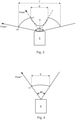
- the first and the second optronics 5, 6 are designed to record the detection areas 7, 8 with horizontal image angles ⁇ 1, ⁇ 2 of different sizes. Not shown here, but alternatively or optionally additionally possible, the detection areas 7, 8 are recorded by the optronics 5, 6 with different vertical angles of view.
- the horizontal angle of view ⁇ 1 of the first detection area 7 is larger than that of the second detection area 8 .
- the first detection area 7 is recorded with a horizontal image angle ⁇ 1 of at least 100 degrees.
- the second detection area 8 is z. B. recorded with a horizontal angle of view ⁇ 2 of at most 50 degrees. There is therefore a larger surrounding area in the first detection area 7 than in the second detection area 8 shown.
- a structural configuration of the optronics 5, 6 is possible which, in the detection areas 7, 8, achieves object recognition in different distance and environmental areas.
- the first and the second detection area 7 , 8 have an overlapping section 9 .
- the overlapping section 9 is therefore an overlapping area of the two detection areas 7, 8.
- the same surrounding area is imaged.
- the overlapping section 9 of the first detection area 7 is only a partial section of the first detection area 7, the second detection area 8 forms the overlapping section 9.
- the vertical and horizontal angle of view ⁇ 2 of the second detection area 8 therefore corresponds to the vertical and horizontal angle of view ⁇ 2 of the overlap section 9.
- the overlapping section 9 recorded by the first optronic unit 6 is a central image area and the remaining area is an edge image area of the first detection area 7 surrounding the central image area .
- the evaluation of only one of the overlapping sections 9 recorded by the detection areas 7, 8 is required.
- the evaluation of this overlapping section 9 is advantageous since the second detection area 8 has a smaller horizontal field of view ⁇ than the first detection area 7 .
- the limited angle of view has the advantage that the second optronics 6 in the overlapping section 9 enables high imaging accuracy with little or no distortion.
- the detection area 7 recorded by the first optronics 5 is shown with the horizontal angle of view ⁇ 1. Since the overlapping section 9 recorded by the second optronic unit 6 is evaluated for object recognition, the first optronic unit 5 is designed to record the overlapping section 9, here the central image area, with a reduced angular resolution than in the remaining area, here the edge image area. The detection area 7 is thus recorded by the first optronics 5 with a non-uniform angular resolution. In this way, on the one hand, a sufficient angular resolution is ensured for the object detection in the edge image area, and on the other hand, the image processing complexity for the first detection area 7 is reduced.
- the first optronic 5 is designed, for example, in such a way that an angular resolution xl of the overlapping section 9 increases rotationally symmetrically, starting from an optical axis A of the first optronic 5 up to the edge image area.
- the first optronic 5 is designed such that the angular resolution xl of the overlapping section 9 increases exponentially starting from the optical axis A of the first optronic 5 up to the transition to the edge image area along the horizontal image angle ⁇ 1.
- the angular resolution xl increases linearly starting from the optical axis A up to the transition to the edge image area or there is no increase up to the transition to the edge image area.
- a minimum value of the angular resolution xl or the angular resolution xl for the entire transition section 9 is five pixels per degree.
- the first optronic unit 5 is designed to record the edge image area with a uniformly distributed angular resolution x2.
- the angular resolution x2 of the edge image area is 20 pixels per degree, so that a sharp image of the edge image area is implemented.
- the detection area 8 recorded by the second optronics 6 is shown with the horizontal angle of view ⁇ 2.
- the second optronics 6 is designed to record the second detection area 8, which forms the overlapping section 9, with a uniformly distributed angular resolution x1.
- the angular resolution xl of the overlapping section 9 is 40 pixels per degree. In this way, a sharp imaging of the overlapping area 9 is implemented and consequently the reliable object recognition in the center image area is made possible. In this way, objects located in the central image area can be located both at close range, e.g. B. vehicles driving ahead, as well as in the long range such as street signs are detected.
- the detection area 7, 8 recorded by the first and the second optronic unit 5, 6 is shown with the horizontal angle of view ⁇ 1, ⁇ 2.
- the angular resolution x2 of the edge image area of the first detection area 7 corresponds to the angular resolution x2 of the second detection area 8. Since the second detection area 8 has a smaller horizontal angle of view ⁇ than the first detection area 7, this increases the image processing complexity compared to the first detection area 7 lower. Alternatively, however, provision can also be made for the second detection area 8 to have a higher angular resolution x1 than the edge image area of the first detection area 7 .
Landscapes
- Engineering & Computer Science (AREA)
- Multimedia (AREA)
- Signal Processing (AREA)
- Physics & Mathematics (AREA)
- General Physics & Mathematics (AREA)
- Theoretical Computer Science (AREA)
- Traffic Control Systems (AREA)
- Studio Devices (AREA)
Claims (10)
- Dispositif formant caméra de véhicule (3) destiné à enregistrer un environnement destiné à la reconnaissance d'objets dans différentes zones situées à distance et dans l'environnement d'un véhicule automobile (2),ledit dispositif comprenant une première et une deuxième optronique (5, 6), la première et la deuxième optronique (5, 6) comprenant chacune un système optique et un capteur d'image,la première optronique (5) étant conçue pour recevoir une première zone de détection (7) et la deuxième optronique (6) étant conçue pour recevoir une deuxième zone de détection (8) de l'environnement,la première et la deuxième optronique (5, 6) ayant des angles d'image (α1, α2) de différentes tailles dont les zones de détection (7, 8) présentent une portion de chevauchement (9),caractérisé en ce que la portion de chevauchement (9) enregistrée par la première optronique (5) présente une résolution angulaire réduite (x1) différente de celle de la zone restante de la première zone de détection (7), la première optronique (5) comportant un capteur d'image qui est conçu pour présenter une résolution qui est plus faible dans la zone d'enregistrement de la portion de chevauchement (9) que dans la zone d'enregistrement restante, et la deuxième zone de détection (8) correspondant à la portion de chevauchement (9).
- Dispositif formant caméra de véhicule (3) selon la revendication 1, la résolution angulaire dans la portion de chevauchement (9) enregistrée par la première optronique (5) étant de 10 pixels par degré maximum.
- Dispositif formant caméra de véhicule (3) selon la revendication 1 ou 2, la portion de chevauchement (9) enregistrée par la première optronique (5) étant enregistrée avec une plus faible résolution angulaire (x1) que la portion de chevauchement (9) enregistrée par la deuxième optronique (6).
- Dispositif formant caméra de véhicule (3) selon l'une des revendications précédentes, la résolution angulaire (xl) dans la portion de chevauchement (9) enregistrée par la deuxième optronique (6) étant d'au moins 20 pixels par degré.
- Dispositif formant caméra de véhicule (3) selon l'une des revendications précédentes, la première optronique (5) étant conçue avec un plus grand angle d'image (α2) que la deuxième optronique (6).
- Dispositif formant caméra de véhicule (3) selon l'une des revendications précédentes, la première optronique (5) étant conçue avec un angle d'image horizontal (α1) d'au moins 80 degrés.
- Dispositif formant caméra de véhicule (3) selon l'une des revendications précédentes, la portion de chevauchement (9) enregistrée par la première optronique (5) étant une zone d'image centrale et la zone restante étant une zone d'image de bord de la première zone de détection (7) qui entoure la zone d'image centrale.
- Dispositif formant caméra de véhicule (3) selon l'une des revendications précédentes, la deuxième optronique (6) étant conçue avec un angle d'image horizontal (α2) d'au moins 20 degrés et/ou de 50 degrés maximum.
- Dispositif d'aide à la conduite (1), comprenant un dispositif formant caméra de véhicule (3) selon l'une des revendications précédentes destiné à la reconnaissance d'objets à partir des zones de détection (7, 8) de l'environnement d'un véhicule automobile (2) qui ont été enregistrées avec le dispositif formant caméra de véhicule (3).
- Dispositif d'aide à la conduite (1) selon la revendication 9, le dispositif d'aide à la conduite (1) étant conçu pour évaluer des feux tricolores, des voies de roulement, des panneaux de signalisation et/ou d'autres usagers de la route à partir des zones de détection enregistrées (7, 8).
Applications Claiming Priority (2)
| Application Number | Priority Date | Filing Date | Title |
|---|---|---|---|
| DE102015215561.7A DE102015215561A1 (de) | 2015-08-14 | 2015-08-14 | Fahrzeugkameravorrichtung zur Aufnahme einer Umgebung eines Kraftfahrzeugs sowie Fahrerassistenzvorrichtung zur Objekterkennung mit einer solchen Fahrzeugkameravorrichtung |
| PCT/DE2016/200299 WO2017028848A1 (fr) | 2015-08-14 | 2016-06-29 | Dispositif de caméra de véhicule pour enregistrer un environnement d'un véhicule automobile ainsi que dispositif d'assistance à la conduite pour reconnaissance d'objet avec un tel dispositif de caméra de véhicule |
Publications (2)
| Publication Number | Publication Date |
|---|---|
| EP3335419A1 EP3335419A1 (fr) | 2018-06-20 |
| EP3335419B1 true EP3335419B1 (fr) | 2022-01-19 |
Family
ID=56555144
Family Applications (1)
| Application Number | Title | Priority Date | Filing Date |
|---|---|---|---|
| EP16745040.2A Active EP3335419B1 (fr) | 2015-08-14 | 2016-06-29 | Dispositif de caméra de véhicule pour enregistrer un environnement d'un véhicule automobile ainsi que dispositif d'assistance à la conduite pour reconnaissance d'objet avec un tel dispositif de caméra de véhicule |
Country Status (5)
| Country | Link |
|---|---|
| US (1) | US10869002B2 (fr) |
| EP (1) | EP3335419B1 (fr) |
| JP (1) | JP2018526873A (fr) |
| DE (2) | DE102015215561A1 (fr) |
| WO (1) | WO2017028848A1 (fr) |
Families Citing this family (7)
| Publication number | Priority date | Publication date | Assignee | Title |
|---|---|---|---|---|
| DE102017205630A1 (de) * | 2017-04-03 | 2018-10-04 | Conti Temic Microelectronic Gmbh | Kameravorrichtung und Verfahren zur Erfassung eines Umgebungsbereichs eines Fahrzeugs |
| JP2018195951A (ja) * | 2017-05-16 | 2018-12-06 | パナソニックIpマネジメント株式会社 | 撮像システム及び移動体制御システム |
| DE102018221995A1 (de) | 2018-12-18 | 2020-06-18 | Conti Temic Microelectronic Gmbh | Synchronisiertes Kamerasystem mit zwei unterschiedlichen Kameras |
| DE102020213267A1 (de) | 2020-10-21 | 2022-04-21 | Conti Temic Microelectronic Gmbh | Helligkeits-Umwandlung von Stereobildern |
| DE102020214622A1 (de) | 2020-11-20 | 2022-05-25 | Conti Temic Microelectronic Gmbh | Auswertung von Bilddaten einer Stereokamera zur Objektbewertung |
| JP7400705B2 (ja) * | 2020-11-30 | 2023-12-19 | トヨタ自動車株式会社 | 撮像システム及び撮像装置 |
| DE102021203927A1 (de) | 2021-04-20 | 2022-10-20 | Continental Autonomous Mobility Germany GmbH | Verfahren und Vorrichtung zur Auswertung von Stereobilddaten eines Kamerasystems basierend auf Signaturen |
Family Cites Families (10)
| Publication number | Priority date | Publication date | Assignee | Title |
|---|---|---|---|---|
| DE102006016673A1 (de) * | 2006-04-08 | 2007-10-11 | Bayerische Motoren Werke Ag | Fahrzeugsichtsystem |
| DE202010002827U1 (de) * | 2010-02-25 | 2010-07-22 | Zdrahal, Sascha | Kameraüberwachungseinrichtung für ein Kraftfahrzeug |
| US8509982B2 (en) * | 2010-10-05 | 2013-08-13 | Google Inc. | Zone driving |
| US9007432B2 (en) * | 2010-12-16 | 2015-04-14 | The Massachusetts Institute Of Technology | Imaging systems and methods for immersive surveillance |
| DE102011103378B3 (de) | 2011-06-03 | 2012-08-23 | Dallmeier Electronic Gmbh & Co. Kg | Überwachungseinrichtung |
| DE102012001835B4 (de) * | 2012-01-31 | 2023-03-02 | Mekra Lang Gmbh & Co. Kg | Sichtsystem für ein Nutzfahrzeug zur Darstellung von gesetzlich vorgeschriebenen Sichtfeldern eines Hauptspiegels und eines Weitwinkelspiegels |
| JP5822866B2 (ja) * | 2013-05-08 | 2015-11-25 | 本田技研工業株式会社 | 画像処理装置 |
| DE102013221878A1 (de) * | 2013-10-28 | 2015-05-21 | Conti Temic Microelectronic Gmbh | Fahrerassistenzsystem mit einer Kamera mit ungleichförmiger Winkelauflösung |
| DE102013221882A1 (de) * | 2013-10-28 | 2015-04-30 | Conti Temic Microelectronic Gmbh | Kamera mit ungleichförmiger Winkelauflösung für ein Fahrzeug |
| DE102014215372A1 (de) * | 2014-08-05 | 2016-02-11 | Conti Temic Microelectronic Gmbh | Fahrerassistenzsystem |
-
2015
- 2015-08-14 DE DE102015215561.7A patent/DE102015215561A1/de not_active Withdrawn
-
2016
- 2016-06-29 JP JP2018501904A patent/JP2018526873A/ja active Pending
- 2016-06-29 DE DE112016002678.1T patent/DE112016002678A5/de not_active Withdrawn
- 2016-06-29 EP EP16745040.2A patent/EP3335419B1/fr active Active
- 2016-06-29 WO PCT/DE2016/200299 patent/WO2017028848A1/fr active Application Filing
-
2018
- 2018-02-12 US US15/894,413 patent/US10869002B2/en active Active
Non-Patent Citations (1)
| Title |
|---|
| None * |
Also Published As
| Publication number | Publication date |
|---|---|
| EP3335419A1 (fr) | 2018-06-20 |
| US20180167587A1 (en) | 2018-06-14 |
| DE112016002678A5 (de) | 2018-03-01 |
| US10869002B2 (en) | 2020-12-15 |
| DE102015215561A1 (de) | 2017-02-16 |
| JP2018526873A (ja) | 2018-09-13 |
| WO2017028848A1 (fr) | 2017-02-23 |
Similar Documents
| Publication | Publication Date | Title |
|---|---|---|
| EP3335419B1 (fr) | Dispositif de caméra de véhicule pour enregistrer un environnement d'un véhicule automobile ainsi que dispositif d'assistance à la conduite pour reconnaissance d'objet avec un tel dispositif de caméra de véhicule | |
| EP2765031B1 (fr) | Système de vision pour véhicules, notamment véhicules utilitaires | |
| EP3488607B1 (fr) | Dispositif de caméra pour l'enregistrement d'une zone environnementale d'un véhicule, et procédé de fourniture d'une fonction d'assistance à un conducteur | |
| EP3488606A1 (fr) | Dispositif de prise de vues et procédé pour capter une zone environnante d'un véhicule équipé dudit dispositif | |
| DE102006010295B4 (de) | Kamerasystem mit zumindest zwei Bildaufnehmern | |
| WO1999037503A1 (fr) | Systeme de surveillance pour vehicules | |
| EP3392692A2 (fr) | Système de caméra pour un véhicule automobile, système de remplacement de miroir doté d'un tel système de caméra et système d'aide à la conduite doté d'un tel système | |
| WO2010076065A1 (fr) | Système de caméra pour un véhicule automobile et véhicule automobile comprenant un système de caméra | |
| DE102007025147B4 (de) | System zur Spurverlassenswarnung und/oder Spurhaltefunktion | |
| WO2015062589A1 (fr) | Caméra à résolution angulaire non uniforme pour un véhicule | |
| DE102016208398B4 (de) | Verfahren zur Kalibrierung einer Fahrzeugkamera | |
| WO2013007701A1 (fr) | Système de caméra destiné à être utilisé dans un véhicule et véhicule équipé d'un tel système de caméra | |
| DE102016218079B3 (de) | Kamera für ein Assistenzsystem eines Fahrzeugs, Assistenzsystem und Fahrzeug | |
| DE102006016673A1 (de) | Fahrzeugsichtsystem | |
| DE102013011533B4 (de) | Erfassungsvorrichtung zum Bestimmen einer Position eines Objekts in einem Innenraum eines Kraftfahrzeugs | |
| DE102019200099A1 (de) | Sensorvorrichtung für ein Ego-Fahrzeug, Fahrerassistenzvorrichtung und Fahrzeug mit einer solchen Sensorvorrichtung | |
| DE102014224903A1 (de) | Optischer Umfeldsensor für Fahrzeuge | |
| EP1962245B1 (fr) | Procédé et dispositif de détermination de l'état de déplacement d'objets | |
| WO2015062603A1 (fr) | Système d'aide à la conduite comportant une caméra à résolution angulaire non uniforme | |
| DE102013102207A1 (de) | Kamerasystem für ein Fahrzeug | |
| DE102012024289A1 (de) | Verfahren zum Umschalten eines Kamerasystems in einen Unterstützungsmodus, Kamerasystem und Kraftfahrzeug | |
| DE102016212730A1 (de) | Fahrzeugkameravorrichtung mit Bildauswertungselektronik | |
| DE102018004776A1 (de) | Verfahren zum Erweitern des Erfassungsbereichs eines Kamerasystems eines Fahrzeugs, Vorrichtung zum Erweitern des Erfassungsbereichs eines Kamerasystems nach einem solchen Verfahren, Fahrzeug mit einer solchen Vorrichtung, und Verwendung des Verfahrens oder der Vorrichtung | |
| DE102014220558A1 (de) | Bilderfassungsvorrichtung für ein fahrzeug und verfahren | |
| DE102020127769A1 (de) | Halterung für ein Mobilgerät am Bord eines Fahrzeugs und Verfahren zum Steuern einer Ausrichtung eines Mobilgeräts an Bord eines Fahrzeugs |
Legal Events
| Date | Code | Title | Description |
|---|---|---|---|
| STAA | Information on the status of an ep patent application or granted ep patent |
Free format text: STATUS: THE INTERNATIONAL PUBLICATION HAS BEEN MADE |
|
| PUAI | Public reference made under article 153(3) epc to a published international application that has entered the european phase |
Free format text: ORIGINAL CODE: 0009012 |
|
| STAA | Information on the status of an ep patent application or granted ep patent |
Free format text: STATUS: REQUEST FOR EXAMINATION WAS MADE |
|
| 17P | Request for examination filed |
Effective date: 20180314 |
|
| AK | Designated contracting states |
Kind code of ref document: A1 Designated state(s): AL AT BE BG CH CY CZ DE DK EE ES FI FR GB GR HR HU IE IS IT LI LT LU LV MC MK MT NL NO PL PT RO RS SE SI SK SM TR |
|
| AX | Request for extension of the european patent |
Extension state: BA ME |
|
| DAV | Request for validation of the european patent (deleted) | ||
| DAX | Request for extension of the european patent (deleted) | ||
| STAA | Information on the status of an ep patent application or granted ep patent |
Free format text: STATUS: EXAMINATION IS IN PROGRESS |
|
| 17Q | First examination report despatched |
Effective date: 20200214 |
|
| STAA | Information on the status of an ep patent application or granted ep patent |
Free format text: STATUS: EXAMINATION IS IN PROGRESS |
|
| RAP1 | Party data changed (applicant data changed or rights of an application transferred) |
Owner name: CONTI TEMIC MICROELECTRONIC GMBH |
|
| GRAP | Despatch of communication of intention to grant a patent |
Free format text: ORIGINAL CODE: EPIDOSNIGR1 |
|
| STAA | Information on the status of an ep patent application or granted ep patent |
Free format text: STATUS: GRANT OF PATENT IS INTENDED |
|
| INTG | Intention to grant announced |
Effective date: 20211007 |
|
| GRAS | Grant fee paid |
Free format text: ORIGINAL CODE: EPIDOSNIGR3 |
|
| GRAA | (expected) grant |
Free format text: ORIGINAL CODE: 0009210 |
|
| STAA | Information on the status of an ep patent application or granted ep patent |
Free format text: STATUS: THE PATENT HAS BEEN GRANTED |
|
| AK | Designated contracting states |
Kind code of ref document: B1 Designated state(s): AL AT BE BG CH CY CZ DE DK EE ES FI FR GB GR HR HU IE IS IT LI LT LU LV MC MK MT NL NO PL PT RO RS SE SI SK SM TR |
|
| REG | Reference to a national code |
Ref country code: GB Ref legal event code: FG4D Free format text: NOT ENGLISH |
|
| REG | Reference to a national code |
Ref country code: CH Ref legal event code: EP |
|
| REG | Reference to a national code |
Ref country code: DE Ref legal event code: R096 Ref document number: 502016014433 Country of ref document: DE |
|
| REG | Reference to a national code |
Ref country code: AT Ref legal event code: REF Ref document number: 1464450 Country of ref document: AT Kind code of ref document: T Effective date: 20220215 |
|
| REG | Reference to a national code |
Ref country code: IE Ref legal event code: FG4D Free format text: LANGUAGE OF EP DOCUMENT: GERMAN |
|
| REG | Reference to a national code |
Ref country code: SE Ref legal event code: TRGR |
|
| REG | Reference to a national code |
Ref country code: LT Ref legal event code: MG9D |
|
| REG | Reference to a national code |
Ref country code: NL Ref legal event code: MP Effective date: 20220119 |
|
| REG | Reference to a national code |
Ref country code: DE Ref legal event code: R081 Ref document number: 502016014433 Country of ref document: DE Owner name: CONTINENTAL AUTONOMOUS MOBILITY GERMANY GMBH, DE Free format text: FORMER OWNER: CONTI TEMIC MICROELECTRONIC GMBH, 90411 NUERNBERG, DE |
|
| PG25 | Lapsed in a contracting state [announced via postgrant information from national office to epo] |
Ref country code: NL Free format text: LAPSE BECAUSE OF FAILURE TO SUBMIT A TRANSLATION OF THE DESCRIPTION OR TO PAY THE FEE WITHIN THE PRESCRIBED TIME-LIMIT Effective date: 20220119 |
|
| PG25 | Lapsed in a contracting state [announced via postgrant information from national office to epo] |
Ref country code: RS Free format text: LAPSE BECAUSE OF FAILURE TO SUBMIT A TRANSLATION OF THE DESCRIPTION OR TO PAY THE FEE WITHIN THE PRESCRIBED TIME-LIMIT Effective date: 20220119 Ref country code: PT Free format text: LAPSE BECAUSE OF FAILURE TO SUBMIT A TRANSLATION OF THE DESCRIPTION OR TO PAY THE FEE WITHIN THE PRESCRIBED TIME-LIMIT Effective date: 20220519 Ref country code: NO Free format text: LAPSE BECAUSE OF FAILURE TO SUBMIT A TRANSLATION OF THE DESCRIPTION OR TO PAY THE FEE WITHIN THE PRESCRIBED TIME-LIMIT Effective date: 20220419 Ref country code: LT Free format text: LAPSE BECAUSE OF FAILURE TO SUBMIT A TRANSLATION OF THE DESCRIPTION OR TO PAY THE FEE WITHIN THE PRESCRIBED TIME-LIMIT Effective date: 20220119 Ref country code: HR Free format text: LAPSE BECAUSE OF FAILURE TO SUBMIT A TRANSLATION OF THE DESCRIPTION OR TO PAY THE FEE WITHIN THE PRESCRIBED TIME-LIMIT Effective date: 20220119 Ref country code: ES Free format text: LAPSE BECAUSE OF FAILURE TO SUBMIT A TRANSLATION OF THE DESCRIPTION OR TO PAY THE FEE WITHIN THE PRESCRIBED TIME-LIMIT Effective date: 20220119 Ref country code: BG Free format text: LAPSE BECAUSE OF FAILURE TO SUBMIT A TRANSLATION OF THE DESCRIPTION OR TO PAY THE FEE WITHIN THE PRESCRIBED TIME-LIMIT Effective date: 20220419 |
|
| PG25 | Lapsed in a contracting state [announced via postgrant information from national office to epo] |
Ref country code: PL Free format text: LAPSE BECAUSE OF FAILURE TO SUBMIT A TRANSLATION OF THE DESCRIPTION OR TO PAY THE FEE WITHIN THE PRESCRIBED TIME-LIMIT Effective date: 20220119 Ref country code: LV Free format text: LAPSE BECAUSE OF FAILURE TO SUBMIT A TRANSLATION OF THE DESCRIPTION OR TO PAY THE FEE WITHIN THE PRESCRIBED TIME-LIMIT Effective date: 20220119 Ref country code: GR Free format text: LAPSE BECAUSE OF FAILURE TO SUBMIT A TRANSLATION OF THE DESCRIPTION OR TO PAY THE FEE WITHIN THE PRESCRIBED TIME-LIMIT Effective date: 20220420 Ref country code: FI Free format text: LAPSE BECAUSE OF FAILURE TO SUBMIT A TRANSLATION OF THE DESCRIPTION OR TO PAY THE FEE WITHIN THE PRESCRIBED TIME-LIMIT Effective date: 20220119 |
|
| PG25 | Lapsed in a contracting state [announced via postgrant information from national office to epo] |
Ref country code: IS Free format text: LAPSE BECAUSE OF FAILURE TO SUBMIT A TRANSLATION OF THE DESCRIPTION OR TO PAY THE FEE WITHIN THE PRESCRIBED TIME-LIMIT Effective date: 20220519 |
|
| REG | Reference to a national code |
Ref country code: DE Ref legal event code: R097 Ref document number: 502016014433 Country of ref document: DE |
|
| PG25 | Lapsed in a contracting state [announced via postgrant information from national office to epo] |
Ref country code: SM Free format text: LAPSE BECAUSE OF FAILURE TO SUBMIT A TRANSLATION OF THE DESCRIPTION OR TO PAY THE FEE WITHIN THE PRESCRIBED TIME-LIMIT Effective date: 20220119 Ref country code: SK Free format text: LAPSE BECAUSE OF FAILURE TO SUBMIT A TRANSLATION OF THE DESCRIPTION OR TO PAY THE FEE WITHIN THE PRESCRIBED TIME-LIMIT Effective date: 20220119 Ref country code: RO Free format text: LAPSE BECAUSE OF FAILURE TO SUBMIT A TRANSLATION OF THE DESCRIPTION OR TO PAY THE FEE WITHIN THE PRESCRIBED TIME-LIMIT Effective date: 20220119 Ref country code: EE Free format text: LAPSE BECAUSE OF FAILURE TO SUBMIT A TRANSLATION OF THE DESCRIPTION OR TO PAY THE FEE WITHIN THE PRESCRIBED TIME-LIMIT Effective date: 20220119 Ref country code: DK Free format text: LAPSE BECAUSE OF FAILURE TO SUBMIT A TRANSLATION OF THE DESCRIPTION OR TO PAY THE FEE WITHIN THE PRESCRIBED TIME-LIMIT Effective date: 20220119 Ref country code: CZ Free format text: LAPSE BECAUSE OF FAILURE TO SUBMIT A TRANSLATION OF THE DESCRIPTION OR TO PAY THE FEE WITHIN THE PRESCRIBED TIME-LIMIT Effective date: 20220119 |
|
| PLBE | No opposition filed within time limit |
Free format text: ORIGINAL CODE: 0009261 |
|
| STAA | Information on the status of an ep patent application or granted ep patent |
Free format text: STATUS: NO OPPOSITION FILED WITHIN TIME LIMIT |
|
| PG25 | Lapsed in a contracting state [announced via postgrant information from national office to epo] |
Ref country code: AL Free format text: LAPSE BECAUSE OF FAILURE TO SUBMIT A TRANSLATION OF THE DESCRIPTION OR TO PAY THE FEE WITHIN THE PRESCRIBED TIME-LIMIT Effective date: 20220119 |
|
| 26N | No opposition filed |
Effective date: 20221020 |
|
| PG25 | Lapsed in a contracting state [announced via postgrant information from national office to epo] |
Ref country code: MC Free format text: LAPSE BECAUSE OF FAILURE TO SUBMIT A TRANSLATION OF THE DESCRIPTION OR TO PAY THE FEE WITHIN THE PRESCRIBED TIME-LIMIT Effective date: 20220119 |
|
| REG | Reference to a national code |
Ref country code: CH Ref legal event code: PL |
|
| REG | Reference to a national code |
Ref country code: BE Ref legal event code: MM Effective date: 20220630 |
|
| PG25 | Lapsed in a contracting state [announced via postgrant information from national office to epo] |
Ref country code: SI Free format text: LAPSE BECAUSE OF FAILURE TO SUBMIT A TRANSLATION OF THE DESCRIPTION OR TO PAY THE FEE WITHIN THE PRESCRIBED TIME-LIMIT Effective date: 20220119 |
|
| GBPC | Gb: european patent ceased through non-payment of renewal fee |
Effective date: 20220629 |
|
| PG25 | Lapsed in a contracting state [announced via postgrant information from national office to epo] |
Ref country code: LU Free format text: LAPSE BECAUSE OF NON-PAYMENT OF DUE FEES Effective date: 20220629 Ref country code: LI Free format text: LAPSE BECAUSE OF NON-PAYMENT OF DUE FEES Effective date: 20220630 Ref country code: IE Free format text: LAPSE BECAUSE OF NON-PAYMENT OF DUE FEES Effective date: 20220629 Ref country code: CH Free format text: LAPSE BECAUSE OF NON-PAYMENT OF DUE FEES Effective date: 20220630 |
|
| PG25 | Lapsed in a contracting state [announced via postgrant information from national office to epo] |
Ref country code: GB Free format text: LAPSE BECAUSE OF NON-PAYMENT OF DUE FEES Effective date: 20220629 Ref country code: BE Free format text: LAPSE BECAUSE OF NON-PAYMENT OF DUE FEES Effective date: 20220630 |
|
| PG25 | Lapsed in a contracting state [announced via postgrant information from national office to epo] |
Ref country code: IT Free format text: LAPSE BECAUSE OF FAILURE TO SUBMIT A TRANSLATION OF THE DESCRIPTION OR TO PAY THE FEE WITHIN THE PRESCRIBED TIME-LIMIT Effective date: 20220119 |
|
| PGFP | Annual fee paid to national office [announced via postgrant information from national office to epo] |
Ref country code: FR Payment date: 20230630 Year of fee payment: 8 Ref country code: DE Payment date: 20230630 Year of fee payment: 8 |
|
| REG | Reference to a national code |
Ref country code: AT Ref legal event code: MM01 Ref document number: 1464450 Country of ref document: AT Kind code of ref document: T Effective date: 20220629 |
|
| PGFP | Annual fee paid to national office [announced via postgrant information from national office to epo] |
Ref country code: SE Payment date: 20230620 Year of fee payment: 8 |
|
| PG25 | Lapsed in a contracting state [announced via postgrant information from national office to epo] |
Ref country code: AT Free format text: LAPSE BECAUSE OF NON-PAYMENT OF DUE FEES Effective date: 20220629 |
|
| PG25 | Lapsed in a contracting state [announced via postgrant information from national office to epo] |
Ref country code: HU Free format text: LAPSE BECAUSE OF FAILURE TO SUBMIT A TRANSLATION OF THE DESCRIPTION OR TO PAY THE FEE WITHIN THE PRESCRIBED TIME-LIMIT; INVALID AB INITIO Effective date: 20160629 |
|
| PG25 | Lapsed in a contracting state [announced via postgrant information from national office to epo] |
Ref country code: MK Free format text: LAPSE BECAUSE OF FAILURE TO SUBMIT A TRANSLATION OF THE DESCRIPTION OR TO PAY THE FEE WITHIN THE PRESCRIBED TIME-LIMIT Effective date: 20220119 Ref country code: CY Free format text: LAPSE BECAUSE OF FAILURE TO SUBMIT A TRANSLATION OF THE DESCRIPTION OR TO PAY THE FEE WITHIN THE PRESCRIBED TIME-LIMIT Effective date: 20220119 |