EP3334519B1 - Vorrichtung und verfahren zum dispergieren mindestens einer substanz in einem fluid - Google Patents
Vorrichtung und verfahren zum dispergieren mindestens einer substanz in einem fluid Download PDFInfo
- Publication number
- EP3334519B1 EP3334519B1 EP16762959.1A EP16762959A EP3334519B1 EP 3334519 B1 EP3334519 B1 EP 3334519B1 EP 16762959 A EP16762959 A EP 16762959A EP 3334519 B1 EP3334519 B1 EP 3334519B1
- Authority
- EP
- European Patent Office
- Prior art keywords
- rotor
- substance
- dispersed
- fluid
- feed line
- Prior art date
- Legal status (The legal status is an assumption and is not a legal conclusion. Google has not performed a legal analysis and makes no representation as to the accuracy of the status listed.)
- Active
Links
- 239000012530 fluid Substances 0.000 title claims description 118
- 239000000126 substance Substances 0.000 title claims description 109
- 238000000034 method Methods 0.000 title claims description 57
- 239000000843 powder Substances 0.000 claims description 109
- 230000008569 process Effects 0.000 claims description 45
- 239000007788 liquid Substances 0.000 claims description 27
- 239000007787 solid Substances 0.000 claims description 23
- 230000000694 effects Effects 0.000 claims description 18
- 230000035515 penetration Effects 0.000 claims description 3
- 238000003780 insertion Methods 0.000 claims 2
- 230000037431 insertion Effects 0.000 claims 2
- 239000006185 dispersion Substances 0.000 description 41
- QDZOEBFLNHCSSF-PFFBOGFISA-N (2S)-2-[[(2R)-2-[[(2S)-1-[(2S)-6-amino-2-[[(2S)-1-[(2R)-2-amino-5-carbamimidamidopentanoyl]pyrrolidine-2-carbonyl]amino]hexanoyl]pyrrolidine-2-carbonyl]amino]-3-(1H-indol-3-yl)propanoyl]amino]-N-[(2R)-1-[[(2S)-1-[[(2R)-1-[[(2S)-1-[[(2S)-1-amino-4-methyl-1-oxopentan-2-yl]amino]-4-methyl-1-oxopentan-2-yl]amino]-3-(1H-indol-3-yl)-1-oxopropan-2-yl]amino]-1-oxo-3-phenylpropan-2-yl]amino]-3-(1H-indol-3-yl)-1-oxopropan-2-yl]pentanediamide Chemical compound C([C@@H](C(=O)N[C@H](CC=1C2=CC=CC=C2NC=1)C(=O)N[C@@H](CC(C)C)C(=O)N[C@@H](CC(C)C)C(N)=O)NC(=O)[C@@H](CC=1C2=CC=CC=C2NC=1)NC(=O)[C@H](CCC(N)=O)NC(=O)[C@@H](CC=1C2=CC=CC=C2NC=1)NC(=O)[C@H]1N(CCC1)C(=O)[C@H](CCCCN)NC(=O)[C@H]1N(CCC1)C(=O)[C@H](N)CCCNC(N)=N)C1=CC=CC=C1 QDZOEBFLNHCSSF-PFFBOGFISA-N 0.000 description 8
- 102100024304 Protachykinin-1 Human genes 0.000 description 8
- 101800003906 Substance P Proteins 0.000 description 8
- 239000000725 suspension Substances 0.000 description 6
- 238000007654 immersion Methods 0.000 description 5
- 238000005086 pumping Methods 0.000 description 5
- 230000009471 action Effects 0.000 description 4
- 230000008878 coupling Effects 0.000 description 4
- 238000010168 coupling process Methods 0.000 description 4
- 238000005859 coupling reaction Methods 0.000 description 4
- 239000000463 material Substances 0.000 description 4
- 239000002245 particle Substances 0.000 description 4
- 230000001133 acceleration Effects 0.000 description 3
- 239000003153 chemical reaction reagent Substances 0.000 description 3
- 239000000839 emulsion Substances 0.000 description 3
- 238000012423 maintenance Methods 0.000 description 3
- 238000003860 storage Methods 0.000 description 3
- 230000008901 benefit Effects 0.000 description 2
- 238000004140 cleaning Methods 0.000 description 2
- 238000007599 discharging Methods 0.000 description 2
- 238000004519 manufacturing process Methods 0.000 description 2
- 239000011236 particulate material Substances 0.000 description 2
- 230000001105 regulatory effect Effects 0.000 description 2
- XLYOFNOQVPJJNP-UHFFFAOYSA-N water Substances O XLYOFNOQVPJJNP-UHFFFAOYSA-N 0.000 description 2
- 230000004888 barrier function Effects 0.000 description 1
- 230000005540 biological transmission Effects 0.000 description 1
- 230000006835 compression Effects 0.000 description 1
- 238000007906 compression Methods 0.000 description 1
- 238000005520 cutting process Methods 0.000 description 1
- 230000007423 decrease Effects 0.000 description 1
- 238000007598 dipping method Methods 0.000 description 1
- 238000006073 displacement reaction Methods 0.000 description 1
- 239000006260 foam Substances 0.000 description 1
- 239000000203 mixture Substances 0.000 description 1
- 238000012986 modification Methods 0.000 description 1
- 230000004048 modification Effects 0.000 description 1
- 230000001590 oxidative effect Effects 0.000 description 1
- 230000000149 penetrating effect Effects 0.000 description 1
- 230000002093 peripheral effect Effects 0.000 description 1
- 230000000704 physical effect Effects 0.000 description 1
- 239000004033 plastic Substances 0.000 description 1
- 239000004810 polytetrafluoroethylene Substances 0.000 description 1
- 229920001343 polytetrafluoroethylene Polymers 0.000 description 1
- 230000008092 positive effect Effects 0.000 description 1
- 230000003068 static effect Effects 0.000 description 1
- 238000009736 wetting Methods 0.000 description 1
Images


Classifications
-
- B—PERFORMING OPERATIONS; TRANSPORTING
- B01—PHYSICAL OR CHEMICAL PROCESSES OR APPARATUS IN GENERAL
- B01F—MIXING, e.g. DISSOLVING, EMULSIFYING OR DISPERSING
- B01F23/00—Mixing according to the phases to be mixed, e.g. dispersing or emulsifying
- B01F23/50—Mixing liquids with solids
- B01F23/53—Mixing liquids with solids using driven stirrers
-
- B—PERFORMING OPERATIONS; TRANSPORTING
- B01—PHYSICAL OR CHEMICAL PROCESSES OR APPARATUS IN GENERAL
- B01F—MIXING, e.g. DISSOLVING, EMULSIFYING OR DISPERSING
- B01F23/00—Mixing according to the phases to be mixed, e.g. dispersing or emulsifying
- B01F23/40—Mixing liquids with liquids; Emulsifying
- B01F23/41—Emulsifying
- B01F23/4105—Methods of emulsifying
-
- B—PERFORMING OPERATIONS; TRANSPORTING
- B01—PHYSICAL OR CHEMICAL PROCESSES OR APPARATUS IN GENERAL
- B01F—MIXING, e.g. DISSOLVING, EMULSIFYING OR DISPERSING
- B01F23/00—Mixing according to the phases to be mixed, e.g. dispersing or emulsifying
- B01F23/50—Mixing liquids with solids
- B01F23/56—Mixing liquids with solids by introducing solids in liquids, e.g. dispersing or dissolving
-
- B—PERFORMING OPERATIONS; TRANSPORTING
- B01—PHYSICAL OR CHEMICAL PROCESSES OR APPARATUS IN GENERAL
- B01F—MIXING, e.g. DISSOLVING, EMULSIFYING OR DISPERSING
- B01F25/00—Flow mixers; Mixers for falling materials, e.g. solid particles
- B01F25/60—Pump mixers, i.e. mixing within a pump
- B01F25/64—Pump mixers, i.e. mixing within a pump of the centrifugal-pump type, i.e. turbo-mixers
- B01F25/642—Pump mixers, i.e. mixing within a pump of the centrifugal-pump type, i.e. turbo-mixers consisting of a stator-rotor system with intermeshing teeth or cages
-
- B—PERFORMING OPERATIONS; TRANSPORTING
- B01—PHYSICAL OR CHEMICAL PROCESSES OR APPARATUS IN GENERAL
- B01F—MIXING, e.g. DISSOLVING, EMULSIFYING OR DISPERSING
- B01F35/00—Accessories for mixers; Auxiliary operations or auxiliary devices; Parts or details of general application
- B01F35/71—Feed mechanisms
- B01F35/717—Feed mechanisms characterised by the means for feeding the components to the mixer
- B01F35/71825—Feed mechanisms characterised by the means for feeding the components to the mixer using means for feeding one phase surrounded by another phase without mixing during the feeding
-
- B—PERFORMING OPERATIONS; TRANSPORTING
- B01—PHYSICAL OR CHEMICAL PROCESSES OR APPARATUS IN GENERAL
- B01F—MIXING, e.g. DISSOLVING, EMULSIFYING OR DISPERSING
- B01F25/00—Flow mixers; Mixers for falling materials, e.g. solid particles
- B01F2025/91—Direction of flow or arrangement of feed and discharge openings
- B01F2025/911—Axial flow
-
- B—PERFORMING OPERATIONS; TRANSPORTING
- B01—PHYSICAL OR CHEMICAL PROCESSES OR APPARATUS IN GENERAL
- B01F—MIXING, e.g. DISSOLVING, EMULSIFYING OR DISPERSING
- B01F25/00—Flow mixers; Mixers for falling materials, e.g. solid particles
- B01F2025/91—Direction of flow or arrangement of feed and discharge openings
- B01F2025/912—Radial flow
-
- B—PERFORMING OPERATIONS; TRANSPORTING
- B01—PHYSICAL OR CHEMICAL PROCESSES OR APPARATUS IN GENERAL
- B01F—MIXING, e.g. DISSOLVING, EMULSIFYING OR DISPERSING
- B01F25/00—Flow mixers; Mixers for falling materials, e.g. solid particles
- B01F2025/91—Direction of flow or arrangement of feed and discharge openings
- B01F2025/919—Direction of flow or arrangement of feed and discharge openings characterised by the disposition of the feed and discharge openings
- B01F2025/9191—Direction of flow or arrangement of feed and discharge openings characterised by the disposition of the feed and discharge openings characterised by the arrangement of the feed openings for one or more flows, e.g. for the mainflow and the flow of an additional component
Definitions
- the present invention relates to an apparatus and a method for dispersing at least one substance in a fluid.
- the invention relates to a device for dispersing a substance in a fluid, in particular in a suitable liquid.
- Dispersion is understood to mean the mixing of at least two substances that do not or hardly dissolve in one another or that combine chemically with one another.
- one substance disperse phase
- another substance continuous phase
- the disperse phase is also liquid, while in the case of a suspension solid particles are finely distributed in a liquid.
- a rotor is moved at a high peripheral speed. This rotation causes a suction that sucks the medium into the rotor and presses it out through the openings, teeth or the like of the stator, whereby the disperse phase is dispersed in the continuous phase.
- DE 4118870 A1 describes a device for wetting and dispersing powders in liquids. In the case of low concentrations, the powder substances are entered in a single pass. At high concentrations, work is carried out in circulation until the final concentration is reached.
- This device uses a classic rotor-stator system that is subject to high wear.
- the built-in stator creates a flow resistance that limits the pumping action of the device.
- DE 3002429 C2 discloses a device for mixing at least one substance with a liquid.
- the substances to be mixed in are introduced into a pipe surrounding the rotor shaft via lateral connecting pipes.
- the liquid enters an annular space between the stator and the tube surrounding the rotor shaft at the open-top end of the stator, reaches the blades of the rotor and then exits again at the lower open end of the stator.
- the substances to be dispersed are introduced through the connecting pipes below the level of the liquid. It is possible to mix the substances to be mixed in below the liquid level in such a way that they do not come into contact with the surrounding atmosphere before mixing.
- grinding media can also be used in the first process area in this machine. However, this leads to a flow resistance which negatively affects the pumping effect. The use of grinding media inside the machine also leads to increased wear, in particular on the cutting device.
- the EP2676725 describes a device for mixing, in particular for dispersing.
- This comprises a housing, a separating device and a rotor unit.
- the separating device divides the housing into a first process area and a second process area.
- a first section of the rotor unit is arranged in the first process area and a second section of the rotor unit is arranged in the second process area.
- the materials to be mixed are fed to the first process area at a distance from the rotor unit. As a result, there is a risk of the powder feed being contaminated by liquid or a liquid-powder mixture.
- the DE2004143 discloses an apparatus for the production of emulsions and suspensions in the form of a centrifugal homogenizer. This uses a rotor-stator system in a multi-row design.
- a multi-part structure usually means increased maintenance costs. In addition, more parts can wear out and have to be replaced accordingly, which leads to increased costs.
- the powder intake pipe and the pipe that feeds the liquid each end at the end face of the rotor, whereby the gap between the mouth of the inlet pipes and the rotor can be adjusted and thus changed.
- the US 2006/0268657 A1 describes an apparatus and a method for mixing a solid with a liquid.
- a rotor is provided in the housing, which is composed of several rotor sections.
- the first rotor section faces a pulse conveying device and is arranged in the solids supply space.
- the first rotor section comprises a pretreatment head for the coarse comminution of the powder agglomerates fed in.
- the second rotor section has a plurality of atomizing knives extending perpendicularly to the rotor axis A for fine atomizing of the previously comminuted powder agglomerates.
- the third rotor section comprises a plurality of conveyor webs.
- Liquid is introduced into the acceleration chamber via a supply line and a tangentially arranged inlet nozzle, which liquid is set in a rotary movement in the acceleration chamber and accelerated to a predetermined speed.
- the liquid flows at a constant rotational speed into the mixing space, where it is mixed with the solid particles.
- the powder particles are transported by the centrifugal movement resulting from the rotary movement in the direction of the liquid layer flowing along the housing wall.
- the NL 39146 C describes a method and an apparatus for producing fire-fighting foam.
- a liquid ring pump with an eccentric is disclosed here.
- a centrifugal pump is provided in front of the liquid ring pump in order to draw in extinguishing water from a storage tank.
- An impeller with radially directed paddles is arranged in the housing. The foam-forming liquid is fed into the interior of the housing via the feed line and water is introduced into the interior of the housing via the nozzle, from where it is conveyed radially by means of the impeller.
- the U.S. 3,503,846 A discloses an apparatus for treating pulp pastes with oxidizing reagents.
- An impeller is provided inside the housing of the device.
- the impeller is sunk upwards and connects to a tapered, pointed part.
- the pointed part comprises a large number of spiral blades, which ensure that the high-consistency material sinks evenly into the chamber of the rotor and that the pressed paste masses and agglomerates are roughly broken up for the first time.
- the rotor includes a plurality of centrifugal blades as well on the recessed part Ledges. Additional blades are provided on the outer edge of the disk, which complete the centrifugal effect of the air volume flow and the particles in suspension in it when it passes through the outlet.
- the mouths of the inlet passages for the reagents and steam are arranged and oriented in such a way that the supplied reagents and vapors are supplied directly to the action of the centrifugal blades.
- the U.S. 3,606,270 A discloses a power mixer for continuously mixing powders or other particulate materials with a liquid.
- the power mixer includes a housing with an impeller having curved impeller blades.
- the housing further comprises an axial inlet extension with an adjoining tube.
- a feed tube for particulate material is provided in the tube.
- Liquid inlets are also provided. The liquid and material can then be mixed by means of the impeller in a mixing zone a. Rotation of the impeller moves the mixed material towards the outlet pipes.
- the object of the invention is to provide an improved device for dispersing at least one substance in a fluid, in particular a device for dispersing at least one powdery substance in a liquid.
- the device should preferably be designed to be more compact and thus more space-saving than devices known from the prior art, and the device should also be of a technically simple design and thus be inexpensive to manufacture and require little maintenance.
- the invention relates to a device for dispersing at least one substance in a fluid.
- a device for dispersing at least one substance in a fluid.
- Such a device comprises a process housing with a rotor, a fluid feed, a feed line for the at least one dispersing substance with at least one outlet opening and a product outlet.
- the rotor is operated, for example, via an electric motor drive which is arranged outside the process housing.
- the rotor is arranged on a drive shaft which, for example, is guided through one of the housing walls of the process housing with a mechanical seal and sealed and is rotatably mounted by means of a bearing.
- the rotor is designed in such a way that an axial conveyance of a supplied fluid can be generated with the rotor at least in some areas. Furthermore, a radial conveyance of the supplied fluid can be generated with the rotor at least in some areas.
- the rotor preferably comprises at least one first means for generating the at least regionally axial conveyance and at least one second means for generating the at least regionally radial conveying of the supplied fluid.
- the areas of axial conveyance and radial conveyance do not overlap, that is, a first area is provided in which predominantly or completely axial conveyance takes place and a second area is provided in the predominantly or completely radial funding takes place. If necessary, an intermediate area can exist in which both axial and radial conveyance takes place. Embodiments are therefore also conceivable in which the areas of the axial and radial conveyance at least partially overlap.
- the supplied fluid is predominantly conveyed axially in a first region. Furthermore, a slight radial conveyance already takes place in this first area, which turns into a completely radial conveyance of the fluid in the direction of the product outlet of the device.
- a preferred embodiment provides that the feed line for the substance to be dispersed is at least partially enclosed by the rotor.
- the at least one outlet opening of the supply line is assigned to a region of the rotor in which the fluid is predominantly conveyed axially.
- the rotor preferably has guide structures that generate the axial conveying effect of the rotor.
- the guide structures are designed in particular in such a way that, on the one hand, they represent the at least one first means for generating the at least regionally axial conveyance and, on the other hand, they form the at least one second means for generating the at least regionally radial conveyance.
- the rotor has a widening cross section, in particular the cross section of the rotor widens on the drive side, that is, in the direction of the rotor side facing away from the feed line for the substance to be dispersed.
- the axial conveyance of the fluid in the area of the at least one outlet opening changes into a radial conveying effect as the rotor cross-section increases.
- the rotation of the rotor generated by the drive means that the fluid is set into rotation.
- the guide structures are formed on the side of the rotor facing the feed line for the substance to be dispersed.
- the rotor has a massive rotor core, the cross section of which - as already described - widens at least in some areas in the direction of the product outlet.
- At least one of the guide structures is extended beyond a solid core of the rotor in the axial direction in the direction of the feed line for the substance to be dispersed.
- a plurality of guide structures is preferably extended beyond a solid core of the rotor in the axial direction in the direction of the feed line for the substance to be dispersed.
- the at least one outlet opening of the feed line for the substance to be dispersed is at least partially enclosed by the at least one elongated guide structure, so that the substance to be dispersed is released from the feed line within structural elements of the rotor.
- the number of elongated conductive structures is variable in relation to the number of total conductive structures.
- a rotor can have such a high density of conductive structures that it is sufficient for the functionality of the conductive structures if only every second conductive structure has an extension beyond the rotor core.
- the feed line for the substance to be dispersed is in particular arranged in such a way that the at least one outlet opening for the substance to be dispersed is at least partially enclosed by the elongated guide structures outside the solid rotor core.
- the rotor has a plurality of guide structures which are formed in the area of the rotor surface. It is It is conceivable to extend only one guide structure beyond the rotor core and to design the extension in such a way that it at least partially or largely all-encompasses the outlet opening for the substance to be dispersed. For example, the extension of one conductive structure could be guided helically around the longitudinal axis of the feed line for the substance to be dispersed.
- the guide structures are designed as a receptacle for the feed line for the substance to be dispersed.
- the guide structures have a central recess in the area of their extension, which is designed to correspond to the feed line for the substance to be dispersed.
- the guide structures are aligned coaxially to the axis of rotation of the rotor in the area of their extension beyond the solid rotor core.
- the extension of the guide structures in particular forms the first means for generating the at least regionally axial conveyance.
- the guide structures in the area of the massive rotor core are curved.
- the curved sub-area of the guide structures in particular forms the second means for generating the at least regionally radial conveyance.
- the curvature of the guide structures results in a high outlet pressure and a good conveying effect.
- the curved guide structures support the radial conveyance when the rotor rotates.
- the elongated guide structures have the effect that an axial conveyance of the fluid towards the massive rotor core or in the direction of the product outlet is achieved already in the area of the at least one outlet opening, although it is arranged outside the solid rotor core.
- the rotation of the rotor also has centrifugal forces that prevent fluid from getting inside.
- the centrifugal forces prevent fluid from being able to penetrate into the receiving area between the elongated guide structures in which the at least one outlet opening is arranged.
- the feed line for the substance to be dispersed has a first longitudinal axis.
- the feed line for the substance to be dispersed is a pipe with a formed first longitudinal axis.
- the rotor is mounted rotatably about an axis of rotation, for example the axis of rotation is formed by the drive shaft.
- the longitudinal axis of the feed line for the substance to be dispersed and the axis of rotation of the rotor can preferably be aligned coaxially or parallel to one another.
- the outlet opening of the feed line for the substance to be dispersed can be arranged in alignment with the longitudinal axis of the feed line for the substance to be dispersed and the axis of rotation of the rotor.
- the feed line for the substance to be dispersed is arranged at an angle to the axis of rotation of the rotor.
- the feed line for the substance to be dispersed ends in the center of the rotor.
- the feed line for the substance to be dispersed which is angled to the rotor axis of rotation, is also arranged in this embodiment in such a way that the at least one outlet opening of the feed line for the substance to be dispersed is at least partially enclosed by the elongated guide structures outside the solid rotor core. This prevents fluid from entering the feed line for the substance to be dispersed. Instead, the fluid is diverted to the outside via the centrifugal forces that occur due to the rotation of the rotor, directly via the guide structures of the rotor.
- the recess formed by the elongated guide structures must be open. This leads to the fact that in the lower area there is a greater distance between the outlet opening of the feed line for the substance to be dispersed and the rotor, while in the upper area the desired small distance between the outlet opening of the feed line and the elongated guide structures of the rotor results.
- the lower, increased distance is not a problem, however, since the fluid does not tend to flow into the supply line from below.
- an essential advantage of this further embodiment with an angled arrangement of the supply line is that the fluid does not enter the supply line for the closed, especially when the device is switched off dispersing substance can flow in.
- the fluid supply is arranged largely orthogonally to the supply line for the substance to be dispersed.
- the fluid supply can have a second longitudinal axis.
- the fluid supply is designed as a tube with a second longitudinal axis.
- the fluid feed is arranged on the process housing at a distance from the rotor, in particular on the side of the feed line for the substance to be dispersed, so that the filled fluid flows around the feed line for the substance to be dispersed at least in some areas.
- the fluid supply is arranged largely at an angle to the supply line for the substance to be dispersed, in particular at an angle between 0 degrees and 90 degrees.
- the fluid is directed outwards from the center of the rotor via the guide structures of the rotor and due to the centrifugal forces that occur when the rotor rotates, so that the fluid cannot reach the central area in which the at least one outlet opening of the feed line for the to dispersing substance is arranged. In particular, the fluid thus does not enter the area of the axis of rotation of the rotor.
- the feed line for the substance to be dispersed can be adjusted axially, in particular the feed line for the substance to be dispersed can be moved axially and / or parallel to the axis of rotation of the rotor relative to the process housing along its longitudinal axis.
- the immersion depth of an end area of the feed line for the substance to be dispersed into the elongated guide structures of the rotor and thus the distance between the at least the end area of the feed line for the substance to be dispersed and the solid core of the rotor, which includes the at least one outlet opening, and the solid core of the rotor can added substance can be changed.
- a radial distance is preferably formed between the elongated guide structures of the rotor and the feed line for the substance to be dispersed.
- Distance is necessary so that the substance can emerge from the at least one outlet opening and pass through between the guide structures into the fluid.
- a gap is formed between the feed line for the substance to be dispersed and the rotor in the axial direction through which the substance passes radially into the fluid.
- the rotor has a plurality of guide structures, only some of the guide structures having axial extensions as first means for generating the at least regionally axial conveyance.
- the rotor has an even number of guide structures, only every second guide structure being extended axially beyond the solid rotor core. This can be particularly useful when there is a high density of conductive structures on the rotor core. In particular, this prevents the extensions from forming such a tight ring around the axis of rotation that a passage of the substance from the supply line into the fluid could be hindered.
- the feed line for the substance to be dispersed can have an increased diameter in the region of the at least one outlet opening, for example in the form of a crank, which serves as an additional deflecting element. This also ensures that no fluid can get into and / or to the at least one outlet opening of the feed line.
- the at least one outlet opening does not have to be designed as an open end of the feed line for the substance to be dispersed.
- the feed line for the substance to be dispersed is formed by a tube, the end of which is closed in the direction of the solid rotor core between the guide structures and which has a plurality of lateral openings in this end area as outlet openings for the substance in the radial direction .
- the substance is also conveyed outwards by the centrifugal forces, that is, in the direction of the outer rotor edge. In doing so, the substance is in the fluid dispersed. This takes place in particular on the outer edge area of the rotor in an interspace between the rotating rotor and the static process housing.
- the inner diameter of the feed line for the substance to be dispersed is variable and can thus be adapted to the requirements of the feed line for the substance to be dispersed.
- the delivery rate and the flow rate can be adjusted.
- format parts reducing the cross section can be pushed into the feed line for the substance to be dispersed in order to vary the diameter and thus the cross-sectional area of the feed line for the substance to be dispersed.
- the variable setting takes place, for example, by using additional inner tubes with smaller diameters for the powder feed tube.
- the inner tubes can for example consist of PTFE or another suitable plastic.
- the rotor and feed tube are exchanged, whereby, for example, several different sizes of rotor and powder feed tube can be available for selection as format parts.
- the first longitudinal axis of the feed line for the substance to be dispersed is oriented horizontally and the second longitudinal axis of the fluid feed is arranged vertically.
- the fluid is supplied from above.
- the fluid enters the process housing via the fluid supply and is captured by the rotor, which accelerates the fluid in the axial and radial directions. This creates a pumping action which pumps the fluid through the product outlet into a container.
- the high pumping effect creates a negative pressure in the process housing.
- suction is created due to the negative pressure in the process housing.
- the substance exits via the at least one outlet opening arranged between the elongated guide structures and merges radially into the fluid.
- the resulting dispersion or suspension is discharged by the rotor from the process housing via the product outlet. Due to the narrow gap between the conductive structures and the feed line for the substance to be dispersed the fluid is prevented by centrifugal forces from flowing into the feed line for the substance to be dispersed.
- the substance to be dispersed can also be fed in gravimetrically.
- the feed line for the substance to be dispersed is positioned vertically or at an angle less than or equal to 70 ° to the vertical.
- the invention further relates to a method for dispersing at least one substance in a fluid, in particular in a liquid, by means of a device comprising a process housing with rotor, a fluid supply, a feed line for the at least one substance to be dispersed with an outlet opening, and a product outlet .
- the rotor brings about an axial conveyance of a supplied fluid, at least in some areas. Furthermore, the rotor brings about a radial conveyance of the supplied fluid, at least in some areas.
- the method can comprise one or more features and / or properties of the device described above.
- the device and the method are suitable for dispersing a substance in a fluid, in particular in a liquid.
- a powdery solid largely without the aid of mechanical forces such as those generated, for example, by a classic rotor-stator system or by the use of grinding media .
- mechanical forces physical effects are used in the device or in the process, for example pressure differences and the associated expansion and compression of air contained in the powder.
- the device is more compact than conventionally known devices. Since the device has a technically simpler structure than known devices, it can be produced more cost-effectively.
- the technically simplified structure facilitates cleaning and maintenance of the device. The simplified cleaning makes the device particularly interesting for small and medium-sized product batches and frequent product changes.
- the device does not use a classic rotor-stator principle to disperse the substance to be dispersed in a fluid.
- a lower shear of the product is advantageous here.
- the device and the method are distinguished by a lower energy input, as a result of which the temperature rise is also lower than in the case of conventionally known devices.
- the device is less prone to failure and / or less prone to wear.
- the device is less sensitive to foreign bodies contained in the powdery substance to be dispersed or in the fluid.
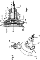
- FIG. 1 shows a schematic cross section of a dispersion device 1 and 1 according to the invention
- Figure 2 shows a perspective view of a dispersion device 1 according to the invention.
- the dispersion device 1 is used in particular to disperse a powdery substance P in a fluid F, in particular a liquid, and to produce a dispersion D in the process.
- the dispersion device 1 comprises a drive motor (not shown), a bearing 9 in which the drive shaft 2 is mounted and a coupling lantern with an internal shaft coupling and drive motor (not shown) for power transmission from the motor shaft to the drive shaft 2.
- the drive shaft 2 is used for the drive of the rotor 3.
- the dispersion device 1 comprises a rotating bearing of the drive shaft 2, which is guided through a mechanical seal 4 into a process housing 5.
- a rotor 3 and a product outlet 8 for discharging the product, in particular the dispersion D, are arranged in the process housing 5 in which the dispersion takes place.
- the process housing 5 is also assigned a supply line for the powdery substance P to be dispersed, in particular a powder supply 6 for supplying powder P, and also a fluid supply 7 for supplying fluid F (cf. Figure 2 ).
- Figure 3 shows a perspective view and Figure 4 shows a schematic sectional illustration of a process housing 5 with powder feed 6, fluid feed 7 and product outlet 8.
- Figures 5 and 6 show different representations of an embodiment of the rotor 3.
- the rotor 3 is rotatable about an axis of rotation R and has a solid rotor core 10.
- the rotor 3 has a cross-sectional area Q which increases at least in regions towards the drive side. In other words, the cross-sectional area Q of the rotor 3 decreases in the direction of the powder supply 6.
- the rotor 3 has a first cross-sectional area Q1 in an area adjacent to the powder supply 6, which is smaller than a second cross-sectional area Q2 in an area of the rotor 3 close to the drive (compare in particular Figure 4 ).
- Guide structures 11 are arranged on the rotor core 10, which guide the fluid F or the powder P in a directional manner.
- Each guide structure 11 essentially comprises two sub-areas 12, 13, the first sub-area 12 being arranged and attached to the solid rotor core 10 and the second sub-area 13 representing an axial extension 14 of the guide structure 11 beyond the solid rotor core 10.
- the guide structures 11 are inclined in the axial direction in the area of the extensions 14 so that they convey in particular axially.
- the guide structures 11 in the first sub-area 12 are additionally curved backwards in order to achieve a high outlet pressure and a good conveying effect.
- the extensions 14 of the guide structures 11 are cut out in the area of the axis of rotation R of the rotor 3 and form an axial opening 15.
- This opening 15 serves in particular as a receptacle 16 for an end area 20 of the powder feed 6 (cf. Figures 1 and 4th ).
- the at least one powder outlet opening 21 of the powder feed 6 is enclosed by the guide structures 11 of the rotor 3 (cf. Figures 1 and 4th ).
- Rotation of the rotor 3 about the axis of rotation R generates centrifugal forces which lead to the fluid F being conducted to the outside and thus being kept away from the powder outlet opening 21.
- penetration of the fluid F into the powder feeder 6 can be effectively prevented.
- the immersion area EB (compare Figures 1 and 4th ), in which the powder feed 6 dips at least in some areas into the rotor 3, in particular the dipping area EB, in which the powder feed 6 dips into the extensions 14 of the guide structures of the rotor 3, thus also the exit area AB, in which the powder P from the at least a powder outlet opening 21 of the powder feed 6 exits and in particular passes over into the fluid F.
- the rotor 3 is preferably shaped in such a way that an axial conveying effect of the fluid F in the direction of the solid rotor core 10 or in the direction of the product outlet 8 is achieved already in the area around the end area 20 of the powder feed 6.
- an axial conveying effect of the fluid F in the direction of the solid rotor core 10 or in the direction of the product outlet 8 is achieved already in the area around the end area 20 of the powder feed 6.
- this axial conveyance changes into a radial conveying effect, up to an area in which the fluid F is only conveyed radially.
- the fluid F is set in rotation by the rotation of the rotor 3 about the axis of rotation R.
- the powder feed 6 can be closed in the end region 20 and have lateral openings as powder outlet openings 21, via which the powder preferably emerges from the powder feed 6 in the radial direction.
- the powder feed 6 can be axially displaced along a longitudinal axis L6.
- the longitudinal axis L6 can preferably be aligned coaxially or parallel to the axis of rotation R of the rotor 2.
- Via the axial displacement of the powder feed 6, in particular the depth that the end region 20 of the powder feed 6 dips into the extensions 14 of the guide structures 11 can be set.
- a spacing is formed between the extensions 14 of the guide structures 11 and the powder feed 6. This distance ensures, in particular, an undisturbed rotation of the rotor 3 around the powder feed 6 and furthermore enables the unimpeded exit of the powder P from the at least one powder outlet opening 21.
- the radial distance between the extensions 14 of the guide structures 11 and the powder feed 6 is preferably between 0.1 mm and 10 mm. It is clear to a person skilled in the art that the spacing is especially tailored to the size of the overall device or to the substances and / or products to be processed.
- a distance A between rotor 3 and process housing 5 is between 0.1 mm and 10 mm.
- the powder feed 6 can have an enlarged outer diameter in the end region 20, in particular in the region of the at least one powder outlet opening 21.
- the increased diameter serves as an additional deflecting element which additionally prevents fluid F from penetrating into the area of the powder outlet opening 21.
- the supply of the fluid F, the powder P or a product suspension or dispersion D takes place via relatively large pipe cross-sections of the powder supply 6 and fluid supply 7. This in particular keeps flow resistances low and products up to medium viscosities can be processed without a pump. If, for example, a product is passed through in the circuit in order to add powder P successively until the desired final concentration is reached, then the addition of the product already containing powder usually takes place via the feed line of the fluid feed 7.
- a valve or the like can be installed at the product inlet of the fluid feed 7 to throttle the flow for products with low viscosities (not shown).
- the supply of fluid F can take place as a function of the respective fluid F or circulating dispersion product D with or without a pump.
- the powder feed 6, which is usually regulated by a valve (not shown) is opened, suction occurs in the process housing 5 due to the negative pressure.
- the powder P is sucked in in the direction of the rotor 3.
- the resulting dispersion D is discharged by the rotor 3 from the process housing 5 via the product outlet 8.
- the narrow gap between the conductive structures 11 and the powder feed 6 prevents the fluid from flowing into the powder feed 6 by means of centrifugal forces.
- valves on the fluid feed 7 or on the powder feed 6 are provided in particular to either open the feed completely or to close it completely in order to prevent the dispersion device 1 from flooding.
- the dispersion device 1 can be used without additional machines. All that is required is a product or batch container (not shown) and a suitable powder feed system (not shown). Conventionally known systems are suitable as the powder feed system, for example a suction lance, a bag feed station, a BigBag feed station, a silo, etc. With the dispersion device 1, powder P can be sucked in and finely dispersed in fluids F, in particular in liquids.
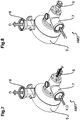
- Figure 7 represents a first working mode AM1 and Figure 8 shows a second working mode AM2.
- the powder feed 6 is open.
- a valve (not shown) regulating the powder feed 6 is open.
- the fluid F or the dispersion product D consisting of powder P dispersed in the fluid F circulates between a product or batch container and the dispersion device 1 (in Figures 7 and 8 only the process housing 5 with the supply and discharge lines 6, 7, 8 is shown in each case, with powder P being continuously supplied, in particular sucked in, via the powder supply 6.
- the powder can be fed in via a funnel, a BigBag station, a silo, a suction lance or the like, for example.
- a second working mode AM2 according to Figure 8 the powder supply 6 is closed by means of a valve (not shown). Instead, the dispersion product D circulates continuously between the product or batch container and the process housing 5 of the dispersion device 1. A strong negative pressure arises in the process housing 5, which leads to (micro) cavitation within the dispersion D. Furthermore, the dispersion product D, that is to say the powder P dispersed in the fluid F, is subjected to a shear effect between the conductive structures 11 and the process housing 5 (cf. Figures 1 and 4th ).
- a further valve (not shown) can be arranged at the product outlet 8 or the product flow is throttled with a corresponding pipeline.
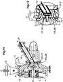
- Figure 9 shows a side view of a further embodiment of a dispersion device 1 according to the invention.
- Figure 10 shows a sectional illustration through the dispersion device 1 according to FIG Figure 9 .
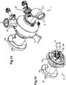
- Figure 11 shows a schematic sectional view and Figure 13 FIG. 13 shows a perspective illustration of the process housing of the embodiment according to FIG Figure 9 .
- Figure 12 provides a detail section Figure 11 dar and Figure 14
- FIG. 11 shows a perspective illustration of a rotor with mounting of the embodiment of the dispersion device 1 according to FIG Figure 9 .
- Identical components are provided with the same reference numbers as in Figures 1 to 8 , to the description of which reference is hereby made.
- the dispersion device 1 comprises a drive motor (not shown), a bearing 9 in which the drive shaft 2 is mounted and a coupling lantern with an internal shaft coupling.
- the dispersion device 1 further comprises a drive motor (not shown) for transmitting power from the motor shaft to the drive shaft 2, which is used to drive the rotor 3.
- a rotating one Support of the drive shaft 2 is provided, which is guided through a mechanical seal 4 into a process housing 5.
- a powdery substance P is dispersed in a fluid F
- a rotor 3 and a product outlet 8 for discharging the product, in particular the dispersion D are arranged.
- the process housing 5 is also assigned a supply line for the powdery substance P to be dispersed, in particular a powder supply 6 *, and also a fluid supply 7 * for supplying fluid F.
- the longitudinal axis L6 * of the powder feed 6 * is arranged at an angle ⁇ to the axis of rotation R of the rotor 3.
- the powdery substance P is thus fed to the rotor 3 obliquely from above to below.
- the powder feed 6 * ends analogously to the powder feed 6 according to FIG Figures 1 and 4th in the center of the rotor 3, in particular, the end region 20 of the powder feed 6 * with the powder outlet opening 21 dips between the axial extensions 14 * of the guide structures 11 of the rotor 3.
- the extensions 14 * of the guide structures 11 are also cut out in the area of the axis of rotation R of the rotor 3 and form an axial opening 15 *.
- This opening 15 * serves in particular as a receptacle 16 * for an end region 20 of the powder feed 6 * (compare in particular Figures 12 and 14th ).
- the at least one powder outlet opening 21 of the powder feed 6 * is enclosed within the receptacle 16 * by the extensions 14 * of the guide structures 11 of the rotor 3 (cf. Figure 10 to 12 ).
- the immersion area EB in which the powder feed 6 * dips into the rotor 3 at least in some areas, in particular the immersion area EB, in which the powder feed 6 * dips into the extensions 14 * of the guide structures 11 of the rotor 3, thus also corresponds to the exit area AB, in which the powder P emerges from the at least one powder outlet opening 21 of the powder feed 6 * and in particular passes into the fluid F.
- the powdery substance P is thus supplied in the center of the rotor 3, as in particular in the enlarged detailed illustration of FIG Figure 12 can be clearly seen.
- the rotor blades or guide structures 11 enclose the end region 20 of the powder feed 6 * and thereby effectively prevent fluid F from getting into the powder feed 6 *.
- the fluid F is centrifuged to the outside through the guide structures 11, in particular via the first partial area 12 of the guide structures 11.
- the special design of the powder feed 6 *, which dips into the rotor blades or guide structures 11, thus forms a dynamic barrier between the powdery substance P and the fluid F.
- the end area 20 of the powder feed 6 * can be cut off in the entry area EB, in which it dips into the rotor 3, such that the end area 20 forms a surface perpendicular to the axis of rotation R of the rotor 3.
- the end region 20 can be cut off at any desired angle to the longitudinal axis L6 * of the powder feed 6 *.
- the angle a at which the powder feed 6 * is arranged to the axis of rotation R of the rotor 3 can be between 0 ° and 90 °.
- the distance between the powder feed 6 * and the rotor 3 can be between 0.5 mm and 100 mm.
- the coverage of the rotor blades or the coverage of the extensions 14 * of the guide structures 11 beyond the powder feed 6 *, in particular the enclosure of the powder feed 6 * by the extensions 14 * of the guide structures 11, can preferably be between 1mm and 100mm.
- the recess between the extensions 14 * which forms the opening 15 * or receptacle 16 *, is designed to be open in order to enable an unhindered rotation of the rotor 3 (cf. Figure 12 ).
- the first distance A1 is greater than the second distance A2.
- the lower area is not a problem, since no fluid F flows into the powder feed 6 * from below.
Landscapes
- Chemical & Material Sciences (AREA)
- Chemical Kinetics & Catalysis (AREA)
- Dispersion Chemistry (AREA)
- Mixers Of The Rotary Stirring Type (AREA)
- Centrifugal Separators (AREA)
Priority Applications (1)
| Application Number | Priority Date | Filing Date | Title |
|---|---|---|---|
| PL16762959T PL3334519T3 (pl) | 2015-08-13 | 2016-07-23 | Urządzenie i sposób do dyspergowania co najmniej jednej substancji w płynie |
Applications Claiming Priority (3)
| Application Number | Priority Date | Filing Date | Title |
|---|---|---|---|
| DE102015113380 | 2015-08-13 | ||
| DE102016102728.6A DE102016102728A1 (de) | 2015-08-13 | 2016-02-17 | Vorrichtung und Verfahren zum Dispergieren mindestens einer Substanz in einem Fluid |
| PCT/DE2016/000287 WO2017025073A1 (de) | 2015-08-13 | 2016-07-23 | Vorrichtung und verfahren zum dispergieren mindestens einer substanz in einem fluid |
Publications (2)
| Publication Number | Publication Date |
|---|---|
| EP3334519A1 EP3334519A1 (de) | 2018-06-20 |
| EP3334519B1 true EP3334519B1 (de) | 2021-05-19 |
Family
ID=57907847
Family Applications (1)
| Application Number | Title | Priority Date | Filing Date |
|---|---|---|---|
| EP16762959.1A Active EP3334519B1 (de) | 2015-08-13 | 2016-07-23 | Vorrichtung und verfahren zum dispergieren mindestens einer substanz in einem fluid |
Country Status (10)
| Country | Link |
|---|---|
| US (1) | US10946355B2 (pt) |
| EP (1) | EP3334519B1 (pt) |
| JP (1) | JP6715322B2 (pt) |
| KR (1) | KR102531425B1 (pt) |
| CN (1) | CN107921382B (pt) |
| BR (1) | BR112018002340B1 (pt) |
| DE (1) | DE102016102728A1 (pt) |
| ES (1) | ES2879389T3 (pt) |
| PL (1) | PL3334519T3 (pt) |
| WO (1) | WO2017025073A1 (pt) |
Families Citing this family (3)
| Publication number | Priority date | Publication date | Assignee | Title |
|---|---|---|---|---|
| CN110385171A (zh) * | 2018-04-23 | 2019-10-29 | 昆山强迪粉碎设备有限公司 | 胶体磨搅拌罐出料装置 |
| CN108993306B (zh) * | 2018-08-13 | 2021-06-25 | 苏州卓诚钛设备有限公司 | 一种内锁紧拆装式的同轴旋转药液搅拌装置 |
| CN116850888B (zh) * | 2023-08-22 | 2024-04-09 | 深圳市尚水智能股份有限公司 | 分散机构及制浆设备 |
Family Cites Families (13)
| Publication number | Priority date | Publication date | Assignee | Title |
|---|---|---|---|---|
| NL39146C (pt) * | ||||
| BE681488A (pt) * | 1965-10-25 | 1966-10-31 | ||
| US3606270A (en) * | 1970-05-14 | 1971-09-20 | Ludish Co | Continuous power blender |
| DE3002429A1 (de) | 1980-01-24 | 1981-07-30 | Ystral Gmbh Maschinenbau Und Processtechnik, 7801 Ballrechten-Dottingen | Vorrichtung zum dispergieren von gas, pulver und fluiden mittels strahlmischer |
| EP0048312A1 (en) * | 1980-09-19 | 1982-03-31 | Nemo Ivarson | Method and apparatus for continuously mixing a liquid and powder |
| DE4118870A1 (de) | 1991-06-07 | 1992-12-17 | Ystral Gmbh Maschinenbau Und P | Vorrichtung zum benetzen und dispergieren von pulvern in fluessigkeiten |
| JP2001062273A (ja) * | 1999-08-27 | 2001-03-13 | Dow Corning Toray Silicone Co Ltd | 連続混合装置 |
| EP1423185B1 (de) * | 2001-08-17 | 2005-01-19 | Netzsch-Feinmahltechnik GmbH | Vorrichtung und verfahren zum vermischen eines feststoffs mit einer flüssigkeit |
| DE10260040A1 (de) * | 2002-12-19 | 2004-07-15 | Braun Gmbh | Mischeinrichtung |
| WO2011053963A1 (en) * | 2009-11-02 | 2011-05-05 | Mannkind Corporation | Reactor for producing pharmaceutical particles in a precipitation process |
| AU2012222534B2 (en) * | 2011-02-28 | 2017-06-08 | Sulzer Mixpac Ag | Dynamic mixer |
| JP5625216B2 (ja) * | 2011-05-31 | 2014-11-19 | 株式会社イズミフードマシナリ | 分散方法及び分散システム |
| EP2676725B1 (de) | 2012-06-18 | 2016-03-02 | Bühler AG | Vorrichtung und Verfahren zum Mischen, insbesondere zum Dispergieren |
-
2016
- 2016-02-17 DE DE102016102728.6A patent/DE102016102728A1/de active Pending
- 2016-07-23 PL PL16762959T patent/PL3334519T3/pl unknown
- 2016-07-23 JP JP2018506888A patent/JP6715322B2/ja active Active
- 2016-07-23 EP EP16762959.1A patent/EP3334519B1/de active Active
- 2016-07-23 KR KR1020187006734A patent/KR102531425B1/ko active IP Right Grant
- 2016-07-23 BR BR112018002340-0A patent/BR112018002340B1/pt active IP Right Grant
- 2016-07-23 US US15/751,816 patent/US10946355B2/en active Active
- 2016-07-23 ES ES16762959T patent/ES2879389T3/es active Active
- 2016-07-23 CN CN201680047460.7A patent/CN107921382B/zh active Active
- 2016-07-23 WO PCT/DE2016/000287 patent/WO2017025073A1/de active Application Filing
Non-Patent Citations (1)
| Title |
|---|
| None * |
Also Published As
| Publication number | Publication date |
|---|---|
| JP2018522727A (ja) | 2018-08-16 |
| BR112018002340A2 (pt) | 2018-10-02 |
| ES2879389T3 (es) | 2021-11-22 |
| WO2017025073A1 (de) | 2017-02-16 |
| JP6715322B2 (ja) | 2020-07-01 |
| KR20180053303A (ko) | 2018-05-21 |
| US10946355B2 (en) | 2021-03-16 |
| CN107921382B (zh) | 2021-09-07 |
| DE102016102728A1 (de) | 2017-02-16 |
| EP3334519A1 (de) | 2018-06-20 |
| US20180236423A1 (en) | 2018-08-23 |
| BR112018002340B1 (pt) | 2022-06-14 |
| KR102531425B1 (ko) | 2023-05-12 |
| CN107921382A (zh) | 2018-04-17 |
| PL3334519T3 (pl) | 2021-11-15 |
Similar Documents
| Publication | Publication Date | Title |
|---|---|---|
| DE1457182C3 (de) | Vorrichtung zum kontinuierlichen Mischen | |
| DE602004003661T2 (de) | Rührmischer | |
| EP2285476B1 (de) | Rotor-stator-system und verfahren zum herstellen von dispersionen | |
| DE69505159T2 (de) | Verfahren und Apparat zum Mischen einer gasförmigen chemischen Substanz zu Fasersuspensionen | |
| EP0516921A1 (de) | Begasungsrührer | |
| DE602005003356T2 (de) | Verfahren, vorrichtung und rotor zur homogenisierung eines mediums | |
| EP3202489B1 (de) | Vorrichtung zum homogenisieren und/oder dispergieren fliessfähiger produkte | |
| EP0570335B1 (de) | Einrichtung und Verfahren zum Beimischen einer schüttbaren Feststoffkomponente zu einer flüssigen Grundmasse | |
| DE3243671C2 (pt) | ||
| EP2572777B1 (de) | Auslasseinrichtung einer rotor-stator-dispergiermaschine | |
| EP3334519B1 (de) | Vorrichtung und verfahren zum dispergieren mindestens einer substanz in einem fluid | |
| DE3342304A1 (de) | Homogenisiermaschine | |
| DE19537303B4 (de) | Vorrichtung zum Homogenisieren fließfähiger Stoffe | |
| EP2305370A1 (de) | Homogenisator und Homogenisiervorrichtung mit einem solchen Homogenisator | |
| EP1964604A2 (de) | Vorrichtung und Verfahren zur kontinuierlichen Herstellung einer Mischung aus wenigstens zwei fließfähigen Phasen | |
| AT511564B1 (de) | Mischvorrichtung und verfahren zum mischen eines schüttgutes oder einer pastösen masse | |
| DE19514384C2 (de) | Misch- oder Dispergiervorrichtung mit einem Leitgehäuse | |
| EP0832682A1 (de) | Einrichtung zum Homogenisieren und Dispergieren von flüssigen Phasen | |
| EP1920822B1 (de) | Vorrichtung und Verfahren zur kontinuierlichen Mischung und Entgasung von festen und/oder flüssigen Substanzen | |
| DE3641413C1 (en) | Apparatus for processing materials | |
| EP3656523A1 (de) | Misch- und knetmaschine mit wirksamer entlüftung im bereich der zuführung, und darauf bezogenes verfahren | |
| DE69730068T2 (de) | Mischvorrichtung | |
| EP4140571A2 (de) | Mischeinrichtung zur herstellung eines fliessfähigen produkts und verfahren zum betrieb einer mischeinrichtung | |
| DE202014003774U1 (de) | Vorrichtung zum Homogenisieren und/oder Dispergieren fließfähiger Produkte | |
| DE102012012146B4 (de) | Mischen und/oder Dispergieren mithilfe eines Sprühteppichs aus einer fließfähigen Masse |
Legal Events
| Date | Code | Title | Description |
|---|---|---|---|
| STAA | Information on the status of an ep patent application or granted ep patent |
Free format text: STATUS: THE INTERNATIONAL PUBLICATION HAS BEEN MADE |
|
| PUAI | Public reference made under article 153(3) epc to a published international application that has entered the european phase |
Free format text: ORIGINAL CODE: 0009012 |
|
| STAA | Information on the status of an ep patent application or granted ep patent |
Free format text: STATUS: REQUEST FOR EXAMINATION WAS MADE |
|
| 17P | Request for examination filed |
Effective date: 20180220 |
|
| AK | Designated contracting states |
Kind code of ref document: A1 Designated state(s): AL AT BE BG CH CY CZ DE DK EE ES FI FR GB GR HR HU IE IS IT LI LT LU LV MC MK MT NL NO PL PT RO RS SE SI SK SM TR |
|
| AX | Request for extension of the european patent |
Extension state: BA ME |
|
| DAV | Request for validation of the european patent (deleted) | ||
| DAX | Request for extension of the european patent (deleted) | ||
| STAA | Information on the status of an ep patent application or granted ep patent |
Free format text: STATUS: EXAMINATION IS IN PROGRESS |
|
| 17Q | First examination report despatched |
Effective date: 20191007 |
|
| STAA | Information on the status of an ep patent application or granted ep patent |
Free format text: STATUS: EXAMINATION IS IN PROGRESS |
|
| GRAP | Despatch of communication of intention to grant a patent |
Free format text: ORIGINAL CODE: EPIDOSNIGR1 |
|
| STAA | Information on the status of an ep patent application or granted ep patent |
Free format text: STATUS: GRANT OF PATENT IS INTENDED |
|
| GRAS | Grant fee paid |
Free format text: ORIGINAL CODE: EPIDOSNIGR3 |
|
| INTG | Intention to grant announced |
Effective date: 20210317 |
|
| GRAA | (expected) grant |
Free format text: ORIGINAL CODE: 0009210 |
|
| STAA | Information on the status of an ep patent application or granted ep patent |
Free format text: STATUS: THE PATENT HAS BEEN GRANTED |
|
| AK | Designated contracting states |
Kind code of ref document: B1 Designated state(s): AL AT BE BG CH CY CZ DE DK EE ES FI FR GB GR HR HU IE IS IT LI LT LU LV MC MK MT NL NO PL PT RO RS SE SI SK SM TR |
|
| REG | Reference to a national code |
Ref country code: GB Ref legal event code: FG4D Free format text: NOT ENGLISH |
|
| REG | Reference to a national code |
Ref country code: CH Ref legal event code: EP |
|
| REG | Reference to a national code |
Ref country code: DE Ref legal event code: R096 Ref document number: 502016013075 Country of ref document: DE |
|
| REG | Reference to a national code |
Ref country code: AT Ref legal event code: REF Ref document number: 1393452 Country of ref document: AT Kind code of ref document: T Effective date: 20210615 |
|
| REG | Reference to a national code |
Ref country code: IE Ref legal event code: FG4D Free format text: LANGUAGE OF EP DOCUMENT: GERMAN |
|
| REG | Reference to a national code |
Ref country code: LT Ref legal event code: MG9D |
|
| REG | Reference to a national code |
Ref country code: NL Ref legal event code: MP Effective date: 20210519 |
|
| PG25 | Lapsed in a contracting state [announced via postgrant information from national office to epo] |
Ref country code: LT Free format text: LAPSE BECAUSE OF FAILURE TO SUBMIT A TRANSLATION OF THE DESCRIPTION OR TO PAY THE FEE WITHIN THE PRESCRIBED TIME-LIMIT Effective date: 20210519 Ref country code: FI Free format text: LAPSE BECAUSE OF FAILURE TO SUBMIT A TRANSLATION OF THE DESCRIPTION OR TO PAY THE FEE WITHIN THE PRESCRIBED TIME-LIMIT Effective date: 20210519 Ref country code: BG Free format text: LAPSE BECAUSE OF FAILURE TO SUBMIT A TRANSLATION OF THE DESCRIPTION OR TO PAY THE FEE WITHIN THE PRESCRIBED TIME-LIMIT Effective date: 20210819 Ref country code: HR Free format text: LAPSE BECAUSE OF FAILURE TO SUBMIT A TRANSLATION OF THE DESCRIPTION OR TO PAY THE FEE WITHIN THE PRESCRIBED TIME-LIMIT Effective date: 20210519 |
|
| REG | Reference to a national code |
Ref country code: ES Ref legal event code: FG2A Ref document number: 2879389 Country of ref document: ES Kind code of ref document: T3 Effective date: 20211122 |
|
| REG | Reference to a national code |
Ref country code: DE Ref legal event code: R079 Ref document number: 502016013075 Country of ref document: DE Free format text: PREVIOUS MAIN CLASS: B01F0003080000 Ipc: B01F0023400000 |
|
| PG25 | Lapsed in a contracting state [announced via postgrant information from national office to epo] |
Ref country code: LV Free format text: LAPSE BECAUSE OF FAILURE TO SUBMIT A TRANSLATION OF THE DESCRIPTION OR TO PAY THE FEE WITHIN THE PRESCRIBED TIME-LIMIT Effective date: 20210519 Ref country code: IS Free format text: LAPSE BECAUSE OF FAILURE TO SUBMIT A TRANSLATION OF THE DESCRIPTION OR TO PAY THE FEE WITHIN THE PRESCRIBED TIME-LIMIT Effective date: 20210919 Ref country code: GR Free format text: LAPSE BECAUSE OF FAILURE TO SUBMIT A TRANSLATION OF THE DESCRIPTION OR TO PAY THE FEE WITHIN THE PRESCRIBED TIME-LIMIT Effective date: 20210820 Ref country code: PT Free format text: LAPSE BECAUSE OF FAILURE TO SUBMIT A TRANSLATION OF THE DESCRIPTION OR TO PAY THE FEE WITHIN THE PRESCRIBED TIME-LIMIT Effective date: 20210920 Ref country code: NO Free format text: LAPSE BECAUSE OF FAILURE TO SUBMIT A TRANSLATION OF THE DESCRIPTION OR TO PAY THE FEE WITHIN THE PRESCRIBED TIME-LIMIT Effective date: 20210819 Ref country code: RS Free format text: LAPSE BECAUSE OF FAILURE TO SUBMIT A TRANSLATION OF THE DESCRIPTION OR TO PAY THE FEE WITHIN THE PRESCRIBED TIME-LIMIT Effective date: 20210519 Ref country code: SE Free format text: LAPSE BECAUSE OF FAILURE TO SUBMIT A TRANSLATION OF THE DESCRIPTION OR TO PAY THE FEE WITHIN THE PRESCRIBED TIME-LIMIT Effective date: 20210519 |
|
| PG25 | Lapsed in a contracting state [announced via postgrant information from national office to epo] |
Ref country code: NL Free format text: LAPSE BECAUSE OF FAILURE TO SUBMIT A TRANSLATION OF THE DESCRIPTION OR TO PAY THE FEE WITHIN THE PRESCRIBED TIME-LIMIT Effective date: 20210519 |
|
| PG25 | Lapsed in a contracting state [announced via postgrant information from national office to epo] |
Ref country code: SK Free format text: LAPSE BECAUSE OF FAILURE TO SUBMIT A TRANSLATION OF THE DESCRIPTION OR TO PAY THE FEE WITHIN THE PRESCRIBED TIME-LIMIT Effective date: 20210519 Ref country code: SM Free format text: LAPSE BECAUSE OF FAILURE TO SUBMIT A TRANSLATION OF THE DESCRIPTION OR TO PAY THE FEE WITHIN THE PRESCRIBED TIME-LIMIT Effective date: 20210519 Ref country code: EE Free format text: LAPSE BECAUSE OF FAILURE TO SUBMIT A TRANSLATION OF THE DESCRIPTION OR TO PAY THE FEE WITHIN THE PRESCRIBED TIME-LIMIT Effective date: 20210519 Ref country code: DK Free format text: LAPSE BECAUSE OF FAILURE TO SUBMIT A TRANSLATION OF THE DESCRIPTION OR TO PAY THE FEE WITHIN THE PRESCRIBED TIME-LIMIT Effective date: 20210519 Ref country code: CZ Free format text: LAPSE BECAUSE OF FAILURE TO SUBMIT A TRANSLATION OF THE DESCRIPTION OR TO PAY THE FEE WITHIN THE PRESCRIBED TIME-LIMIT Effective date: 20210519 Ref country code: RO Free format text: LAPSE BECAUSE OF FAILURE TO SUBMIT A TRANSLATION OF THE DESCRIPTION OR TO PAY THE FEE WITHIN THE PRESCRIBED TIME-LIMIT Effective date: 20210519 |
|
| REG | Reference to a national code |
Ref country code: DE Ref legal event code: R097 Ref document number: 502016013075 Country of ref document: DE |
|
| PLBE | No opposition filed within time limit |
Free format text: ORIGINAL CODE: 0009261 |
|
| STAA | Information on the status of an ep patent application or granted ep patent |
Free format text: STATUS: NO OPPOSITION FILED WITHIN TIME LIMIT |
|
| PG25 | Lapsed in a contracting state [announced via postgrant information from national office to epo] |
Ref country code: MC Free format text: LAPSE BECAUSE OF FAILURE TO SUBMIT A TRANSLATION OF THE DESCRIPTION OR TO PAY THE FEE WITHIN THE PRESCRIBED TIME-LIMIT Effective date: 20210519 |
|
| REG | Reference to a national code |
Ref country code: BE Ref legal event code: MM Effective date: 20210731 |
|
| 26N | No opposition filed |
Effective date: 20220222 |
|
| PG25 | Lapsed in a contracting state [announced via postgrant information from national office to epo] |
Ref country code: IS Free format text: LAPSE BECAUSE OF FAILURE TO SUBMIT A TRANSLATION OF THE DESCRIPTION OR TO PAY THE FEE WITHIN THE PRESCRIBED TIME-LIMIT Effective date: 20210919 Ref country code: LU Free format text: LAPSE BECAUSE OF NON-PAYMENT OF DUE FEES Effective date: 20210723 Ref country code: AL Free format text: LAPSE BECAUSE OF FAILURE TO SUBMIT A TRANSLATION OF THE DESCRIPTION OR TO PAY THE FEE WITHIN THE PRESCRIBED TIME-LIMIT Effective date: 20210519 |
|
| PG25 | Lapsed in a contracting state [announced via postgrant information from national office to epo] |
Ref country code: IE Free format text: LAPSE BECAUSE OF NON-PAYMENT OF DUE FEES Effective date: 20210723 Ref country code: BE Free format text: LAPSE BECAUSE OF NON-PAYMENT OF DUE FEES Effective date: 20210731 |
|
| REG | Reference to a national code |
Ref country code: AT Ref legal event code: MM01 Ref document number: 1393452 Country of ref document: AT Kind code of ref document: T Effective date: 20210723 |
|
| PG25 | Lapsed in a contracting state [announced via postgrant information from national office to epo] |
Ref country code: AT Free format text: LAPSE BECAUSE OF NON-PAYMENT OF DUE FEES Effective date: 20210723 |
|
| PG25 | Lapsed in a contracting state [announced via postgrant information from national office to epo] |
Ref country code: HU Free format text: LAPSE BECAUSE OF FAILURE TO SUBMIT A TRANSLATION OF THE DESCRIPTION OR TO PAY THE FEE WITHIN THE PRESCRIBED TIME-LIMIT; INVALID AB INITIO Effective date: 20160723 |
|
| PG25 | Lapsed in a contracting state [announced via postgrant information from national office to epo] |
Ref country code: CY Free format text: LAPSE BECAUSE OF FAILURE TO SUBMIT A TRANSLATION OF THE DESCRIPTION OR TO PAY THE FEE WITHIN THE PRESCRIBED TIME-LIMIT Effective date: 20210519 |
|
| PGFP | Annual fee paid to national office [announced via postgrant information from national office to epo] |
Ref country code: TR Payment date: 20230713 Year of fee payment: 8 Ref country code: IT Payment date: 20230727 Year of fee payment: 8 Ref country code: GB Payment date: 20230720 Year of fee payment: 8 Ref country code: ES Payment date: 20230801 Year of fee payment: 8 Ref country code: CH Payment date: 20230801 Year of fee payment: 8 |
|
| PGFP | Annual fee paid to national office [announced via postgrant information from national office to epo] |
Ref country code: FR Payment date: 20230721 Year of fee payment: 8 Ref country code: DE Payment date: 20230724 Year of fee payment: 8 |
|
| PG25 | Lapsed in a contracting state [announced via postgrant information from national office to epo] |
Ref country code: MK Free format text: LAPSE BECAUSE OF FAILURE TO SUBMIT A TRANSLATION OF THE DESCRIPTION OR TO PAY THE FEE WITHIN THE PRESCRIBED TIME-LIMIT Effective date: 20210519 |
|
| PGFP | Annual fee paid to national office [announced via postgrant information from national office to epo] |
Ref country code: PL Payment date: 20240625 Year of fee payment: 9 |