EP3334508B1 - Vorrichtungen und komponenten aus legierungsmaterial - Google Patents
Vorrichtungen und komponenten aus legierungsmaterial Download PDFInfo
- Publication number
- EP3334508B1 EP3334508B1 EP16835971.9A EP16835971A EP3334508B1 EP 3334508 B1 EP3334508 B1 EP 3334508B1 EP 16835971 A EP16835971 A EP 16835971A EP 3334508 B1 EP3334508 B1 EP 3334508B1
- Authority
- EP
- European Patent Office
- Prior art keywords
- alloy material
- sample
- column
- separation
- wetted
- Prior art date
- Legal status (The legal status is an assumption and is not a legal conclusion. Google has not performed a legal analysis and makes no representation as to the accuracy of the status listed.)
- Active
Links
Images


Classifications
-
- B—PERFORMING OPERATIONS; TRANSPORTING
- B01—PHYSICAL OR CHEMICAL PROCESSES OR APPARATUS IN GENERAL
- B01D—SEPARATION
- B01D15/00—Separating processes involving the treatment of liquids with solid sorbents; Apparatus therefor
- B01D15/08—Selective adsorption, e.g. chromatography
- B01D15/10—Selective adsorption, e.g. chromatography characterised by constructional or operational features
- B01D15/22—Selective adsorption, e.g. chromatography characterised by constructional or operational features relating to the construction of the column
-
- B—PERFORMING OPERATIONS; TRANSPORTING
- B01—PHYSICAL OR CHEMICAL PROCESSES OR APPARATUS IN GENERAL
- B01D—SEPARATION
- B01D53/00—Separation of gases or vapours; Recovering vapours of volatile solvents from gases; Chemical or biological purification of waste gases, e.g. engine exhaust gases, smoke, fumes, flue gases, aerosols
- B01D53/02—Separation of gases or vapours; Recovering vapours of volatile solvents from gases; Chemical or biological purification of waste gases, e.g. engine exhaust gases, smoke, fumes, flue gases, aerosols by adsorption, e.g. preparative gas chromatography
- B01D53/025—Separation of gases or vapours; Recovering vapours of volatile solvents from gases; Chemical or biological purification of waste gases, e.g. engine exhaust gases, smoke, fumes, flue gases, aerosols by adsorption, e.g. preparative gas chromatography with wetted adsorbents; Chromatography
-
- C—CHEMISTRY; METALLURGY
- C12—BIOCHEMISTRY; BEER; SPIRITS; WINE; VINEGAR; MICROBIOLOGY; ENZYMOLOGY; MUTATION OR GENETIC ENGINEERING
- C12M—APPARATUS FOR ENZYMOLOGY OR MICROBIOLOGY; APPARATUS FOR CULTURING MICROORGANISMS FOR PRODUCING BIOMASS, FOR GROWING CELLS OR FOR OBTAINING FERMENTATION OR METABOLIC PRODUCTS, i.e. BIOREACTORS OR FERMENTERS
- C12M21/00—Bioreactors or fermenters specially adapted for specific uses
- C12M21/18—Apparatus specially designed for the use of free, immobilized or carrier-bound enzymes
-
- C—CHEMISTRY; METALLURGY
- C12—BIOCHEMISTRY; BEER; SPIRITS; WINE; VINEGAR; MICROBIOLOGY; ENZYMOLOGY; MUTATION OR GENETIC ENGINEERING
- C12M—APPARATUS FOR ENZYMOLOGY OR MICROBIOLOGY; APPARATUS FOR CULTURING MICROORGANISMS FOR PRODUCING BIOMASS, FOR GROWING CELLS OR FOR OBTAINING FERMENTATION OR METABOLIC PRODUCTS, i.e. BIOREACTORS OR FERMENTERS
- C12M23/00—Constructional details, e.g. recesses, hinges
- C12M23/20—Material Coatings
-
- G—PHYSICS
- G01—MEASURING; TESTING
- G01N—INVESTIGATING OR ANALYSING MATERIALS BY DETERMINING THEIR CHEMICAL OR PHYSICAL PROPERTIES
- G01N30/00—Investigating or analysing materials by separation into components using adsorption, absorption or similar phenomena or using ion-exchange, e.g. chromatography or field flow fractionation
- G01N30/02—Column chromatography
- G01N30/60—Construction of the column
- G01N30/6052—Construction of the column body
- G01N30/6073—Construction of the column body in open tubular form
-
- G—PHYSICS
- G01—MEASURING; TESTING
- G01N—INVESTIGATING OR ANALYSING MATERIALS BY DETERMINING THEIR CHEMICAL OR PHYSICAL PROPERTIES
- G01N30/00—Investigating or analysing materials by separation into components using adsorption, absorption or similar phenomena or using ion-exchange, e.g. chromatography or field flow fractionation
- G01N30/02—Column chromatography
- G01N30/60—Construction of the column
- G01N30/6095—Micromachined or nanomachined, e.g. micro- or nanosize
-
- B—PERFORMING OPERATIONS; TRANSPORTING
- B01—PHYSICAL OR CHEMICAL PROCESSES OR APPARATUS IN GENERAL
- B01D—SEPARATION
- B01D2253/00—Adsorbents used in seperation treatment of gases and vapours
- B01D2253/10—Inorganic adsorbents
- B01D2253/112—Metals or metal compounds not provided for in B01D2253/104 or B01D2253/106
- B01D2253/1122—Metals
-
- B—PERFORMING OPERATIONS; TRANSPORTING
- B01—PHYSICAL OR CHEMICAL PROCESSES OR APPARATUS IN GENERAL
- B01L—CHEMICAL OR PHYSICAL LABORATORY APPARATUS FOR GENERAL USE
- B01L3/00—Containers or dishes for laboratory use, e.g. laboratory glassware; Droppers
- B01L3/50—Containers for the purpose of retaining a material to be analysed, e.g. test tubes
- B01L3/502—Containers for the purpose of retaining a material to be analysed, e.g. test tubes with fluid transport, e.g. in multi-compartment structures
- B01L3/5027—Containers for the purpose of retaining a material to be analysed, e.g. test tubes with fluid transport, e.g. in multi-compartment structures by integrated microfluidic structures, i.e. dimensions of channels and chambers are such that surface tension forces are important, e.g. lab-on-a-chip
- B01L3/502753—Containers for the purpose of retaining a material to be analysed, e.g. test tubes with fluid transport, e.g. in multi-compartment structures by integrated microfluidic structures, i.e. dimensions of channels and chambers are such that surface tension forces are important, e.g. lab-on-a-chip characterised by bulk separation arrangements on lab-on-a-chip devices, e.g. for filtration or centrifugation
-
- G—PHYSICS
- G01—MEASURING; TESTING
- G01N—INVESTIGATING OR ANALYSING MATERIALS BY DETERMINING THEIR CHEMICAL OR PHYSICAL PROPERTIES
- G01N30/00—Investigating or analysing materials by separation into components using adsorption, absorption or similar phenomena or using ion-exchange, e.g. chromatography or field flow fractionation
- G01N30/02—Column chromatography
- G01N30/88—Integrated analysis systems specially adapted therefor, not covered by a single one of the groups G01N30/04 - G01N30/86
- G01N2030/8809—Integrated analysis systems specially adapted therefor, not covered by a single one of the groups G01N30/04 - G01N30/86 analysis specially adapted for the sample
- G01N2030/8813—Integrated analysis systems specially adapted therefor, not covered by a single one of the groups G01N30/04 - G01N30/86 analysis specially adapted for the sample biological materials
- G01N2030/8831—Integrated analysis systems specially adapted therefor, not covered by a single one of the groups G01N30/04 - G01N30/86 analysis specially adapted for the sample biological materials involving peptides or proteins
-
- G—PHYSICS
- G01—MEASURING; TESTING
- G01N—INVESTIGATING OR ANALYSING MATERIALS BY DETERMINING THEIR CHEMICAL OR PHYSICAL PROPERTIES
- G01N30/00—Investigating or analysing materials by separation into components using adsorption, absorption or similar phenomena or using ion-exchange, e.g. chromatography or field flow fractionation
- G01N30/02—Column chromatography
- G01N30/62—Detectors specially adapted therefor
- G01N30/72—Mass spectrometers
- G01N30/7233—Mass spectrometers interfaced to liquid or supercritical fluid chromatograph
- G01N30/724—Nebulising, aerosol formation or ionisation
- G01N30/7266—Nebulising, aerosol formation or ionisation by electric field, e.g. electrospray
Definitions
- This disclosure relates to materials for chromatographic separation devices and components and materials for immobilized enzymatic reactor devices and components, in particular to a device for separating a sample by chromatography.
- Chromatographic techniques are important tools for the identification and separation of complex samples.
- the basic principle underlying chromatographic techniques is the separation of a mixture into individual components by transporting the mixture in a moving fluid through a retentive media in a separation channel (e.g., a separation column).
- the moving fluid is typically referred to as the mobile phase and the retentive media is typically referred to as the stationary phase.
- the separation of the various constituents of the mixture is based on differential partitioning between the mobile and stationary phases. Differences in components' partition coefficient result in differential retention on the stationary phase, resulting in separation.
- a detector positioned at the outlet end of the separation channel, detects each of the separated components as they exit the separation channel yielding a chromatogram.
- GC gas chromatography
- LC liquid chromatography
- HPLC high-performance liquid chromatography
- UHPLC ultra-high performance liquid chromatography
- the sample is forced by a liquid at high pressure, which is the mobile phase, through a separation channel (e.g., a column) that is packed with a stationary phase, which is typically composed of irregularly or spherically shaped particles.
- the stationary phase may be a monolithic solid.
- Some exemplary embodiments include devices for separating a sample by chromatography and components for chromatographic separation devices.
- the devices or components have a wetted surface exposed to a mobile phase including the sample during chromatographic separation.
- the wetted surface includes an alloy material comprising nickel, cobalt, molybdenum and chromium and limited in an amount of titanium
- the alloy material of the wetted surface enables chromatography of samples containing peptides (e.g., histidine-containing peptides) with narrow peaks for the peptide components and without significant peak tailing of the peptide components.
- the alloy material is more corrosion-resistant that other materials, such as stainless steel, employed in some chromatographic separation devices.
- the enhanced corrosion resistance of alloys employed may increase a useful lifetime of chromatographic separation devices and components.
- Devices for separating a sample by chromatography have wetted surfaces exposed to a mobile phase including the sample with one or more of the wetted surfaces including an alloy material selected to resist adsorption of proteins and peptides present in the sample.
- the alloy material is limited in an amount of titanium (i.e., less than 0.1 wt% titanium), e.g. less than 0.05 wt% titanium, less than 0.015 wt% titanium, less than 0.01 wt% titanium, less than 0.005 wt% titanium, less than 0.001 wt% titanium.
- the alloy material has a composition of about 35 wt% cobalt, 35 wt% nickel, 20 wt% chromium, and 10 wt% molybdenum and is limited in an amount of titanium.
- the alloy material is included in a surface portion of a chromatography component or separation channel with a bulk portion of the chromatography component or separation channel includes a different material.
- the surface portion and the bulk portion are diffusion bonded to each other.
- the components and devices having wetted surfaces including the alloy material are configured for use in microfluidic separation devices or systems (e.g., where a width or diameter of a separation channel falls in a range of 20 ⁇ m to 500 ⁇ m). In some aspects, the components and devices having wetted surfaces including the alloy material are configured for use at high pressures ( e.g., at pressures in a range of 41.37 to 103.4 MPa (6,000 to 15,000 psi)).
- the invention provides a device for separating a sample by chromatography as recited by Claim 1.
- the wall includes a surface portion including the wetted surface and a bulk portion, and the composition of the alloy material of the wetted surface is different than a composition of a material of the bulk portion.
- the surface portion is diffusion bonded to the bulk portion.
- most or all of the thickness of the wall may be made of the alloy.
- the wetted surface of the wall defines a separation channel.
- the device further includes an electrospray tip at an outlet of the separation channel and a wetted surface of the electrospray tip includes the alloy material.
- the device includes two or more sheets of the alloy material, a portion of each sheet forming a portion of the wall. In some embodiments, the two or more sheets are diffusion bonded at an interface with at least a portion of the separation channel extending along the interface.
- the device includes two or more sheets, each sheet including a layer of the alloy material and each sheet forming a portion of the wall with the layer of alloy material of the sheet forming the wetted surface for the portion of the wall.
- the layers of the alloy material of the two or more sheets are diffusion bonded at an interface with at least a portion of the separation channel extending along the interface.
- the device also includes an end fitting and wetted surfaces of the end fitting include the alloy material.
- the device also includes a seal ring and wetted surfaces of the seal ring include the alloy material.
- the seal ring includes a frit and wetted surfaces of the frit include the alloy material.
- the device also includes a frit and wetted surfaces of the frit comprise the alloy material.
- the device also includes a weir and wetted surfaces of the weir comprise the alloy material.
- the device also includes one or more integrated valves, and wetted surfaces of the one or more integrated valves comprise the alloy material.
- the device also includes a distributor disk and wetted surfaces of the distributor disk include the alloy material.
- all surfaces of the device upstream of an outlet end of the separation channel and configured to be in contact with the mobile phase including the sample during use, excluding the stationary phase, include the alloy material.
- the width or diameter of the separation channel falls in a range of 500 ⁇ m to 50 mm.
- the device is a microfluidic device and the width or diameter of the separation channel falls in a range of 20 ⁇ m to 500 ⁇ m.
- the width or diameter of the separation channel falls in a range of 500 ⁇ m to 50 mm.
- a component configured for use in a device for separating a sample by chromatography includes a body having a wetted surface exposed to a mobile phase including the sample during chromatographic separation.
- the wetted surface defines a separation channel through which the mobile phase including the sample flows during use. In some embodiments, a width or diameter of the separation channel is between 20 ⁇ m and 500 ⁇ m.
- the component further includes an electrospray tip at an outlet of the separation channel, and the wetted surface of the body includes a wetted surface of the electrospray tip.
- the component further includes one or more integrated valves, and wetted surfaces of the one or more integrated valves include the alloy material.
- the component is an end fitting for an inlet or an outlet of a separation column.
- the component is a stationary phase retaining element configured to keep a stationary phrase within a separation channel of the device.
- the stationary phase retaining element is a frit.
- the stationary phase retaining element is a weir structure.
- the body includes a surface portion including the wetted surface and a bulk portion, and a composition of the alloy material of the wetted surface is the same as a composition of a material of the bulk portion. In some embodiments, the body includes a surface portion including the wetted surface and a bulk portion, and a composition of the alloy material of wetted surface is different than a composition of a material of the body portion. In some embodiments, the surface portion is diffusion bonded to the bulk portion.
- the wetted surface consists of the alloy material.
- a solid body configured for use as at least part of a stationary phase in a chromatographic separation device includes an alloy material as described herein.
- a method of performing chromatographic separation on a sample includes providing a chromatographic separation device including a separation channel. The method also includes flowing a mobile phase carrying the sample into and through the separation channel, thereby performing chromatographic separation on the sample.
- the method also includes detecting components of the sample downstream of the separation channel.
- the sample includes proteins and the proteins in the sample are separated and detected. In some embodiments, the sample includes peptides and the peptides in the sample are separated and detected. In some embodiments, the sample comprises histidine-containing peptides and the histidine-containing peptides in the sample are separated and detected. In some embodiments, the sample includes phosphopeptides and the phosphopeptides in the sample are separated and detected.
- the method also includes detecting components of the sample downstream of the separation channel where the sample includes one or more of proteins or peptides, and the one or more proteins or peptides in the sample are separated and detected with a tailing factor of less than 1.3.
- a method of performing chromatographic separation includes providing a chromatographic separation device in accordance with any embodiments described herein and flowing a mobile phase carrying a sample through the chromatographic separation device, thereby separating components of the sample.
- Some exemplary embodiments includes devices of components for performing enzymatic reactions that may be part of immobilized enzymatic reactor (IMER) systems.
- the devices configured for performing enzymatic reactions include a wall defining a chamber having an inlet and an outlet with the wall having a wetted surface exposed to a liquid sample during use.
- the wetted surface of the wall includes any of the alloy materials described herein.
- the components configured for performing enzymatic reactions include a body having a having a wetted surface exposed to a liquid sample during use with the wetted surface including any of the alloys described herein.
- the wall or the body comprises a surface portion including the wetted surface and a bulk portion, and the composition of the alloy material of the wetted surface is different than a composition of a material of the bulk portion.
- the surface portion is diffusion bonded to the bulk portion.
- the surface portion consists of the alloy material.
- the alloy material is limited in an amount of titanium to 0.1 wt%. In some embodiments, the alloy material is limited in an amount of titanium to 0.05 wt%. In some embodiments, the alloy material is limited in an amount of titanium to 0.02 wt%. In some embodiments, the alloy material is limited in an amount of titanium to 0.015 wt%. In some embodiments, the alloy material is limited in an amount of titanium to less than 0.01 wt%. In some embodiments, the alloy material is limited in an amount of titanium to less than 0.005 wt%. In some embodiments, the alloy material is limited in an amount of titanium to less than 0.001 wt% titanium.
- the alloy material includes both cobalt and chromium as constituents.
- the alloy material further includes molybdenum as a constituent.
- the alloy material includes the following constituents: 32 wt%-38 wt% cobalt; 32 wt%-38 wt% nickel; 17 wt%-23 wt% chromium; and 7 wt% -13 wt% molybdenum; and limited in an amount of titanium to 0.1 wt%; and a remainder being limited to a total of 5 wt%. In some embodiments, the remainder is limited to a total of 3 wt%.
- the alloy material includes the following constituents: 34 wt%-36 wt% cobalt; 34 wt%-36 wt% nickel; 19 wt%-21 wt% chromium; and 9 wt% -11 wt% molybdenum; and limited in an amount of titanium to 0.05 wt%; and a remainder being limited to a total of 5 wt%. In some embodiments, the remainder is limited to a total of 3 wt%.
- a wetted surface consists of the alloy material. In some embodiments, most of the surface area of the wetted surface is covered by the alloy material. In some embodiments, over 90% of the surface area of the wetted surface is covered by the alloy material. In some embodiments, over 95% of the surface area of the wetted surface is covered by the alloy material. In some embodiments, over 98% of the surface area of the wetted surface is covered by the alloy material. In some embodiments, over 99% of the surface area of the wetted surface is covered by the alloy material.
- the device or component is configured for use in ion exchange chromatography. In some embodiments, the device or component is configured for use in reversed-phase chromatography.
- the device or component is configured to withstand pressures used in high performance liquid chromatography. In some embodiments, the device or component is configured to withstand pressures used in ultra-high performance liquid chromatography. In some embodiments, the device or component is configured to withstand pressures of 103.4 to 137.9 MPa (15,000 to 20,000 psi). In some embodiments, the device or component is configured to withstand pressures of 137.9 to 344.7 MPa (20,000 psi to 50,000 psi). In some embodiments, the device or component is configured for low pressure applications.
- the alloy material is resistant to adsorption of proteins and resistant to adsorption of peptides. In some embodiments, the alloy material is resistant to adsorption of histidine-containing peptides. In some embodiments, the alloy material is resistant to adsorption of phosphopeptides.
- Stainless steel has been widely used as column hardware (e.g., HPLC hardware or UPLC hardware) for chromatographic separation.
- column hardware e.g., HPLC hardware or UPLC hardware
- some components of biological samples such as peptides and proteins, often adsorb to column hardware of stainless steel and similar metals during analysis. It has been theorized that the adsorption is due to interaction between the peptides and the iron contained in the metal.
- the adsorption to column hardware during analysis causes disappearance of or reduced signal from these components in the chromatogram, or substantial peak broadening (see description accompanying FIG. 11 below).
- the effect of the adsorption on the chromatograph may vary for subsequent injections until the adsorption on the hardware reaches a saturation level, indicating that the column needs to be conditioned prior to analysis (see description accompanying FIG. 14 below).
- Stainless steel column hardware can be conditioned by injecting large quantities of peptide or protein prior to the analysis, which reduces the amount of adsorption of these components from samples during analysis. However, this may only be a temporary fix. Further, conditioning may waste sample and increases the time and effort required to obtain useful results.
- non-metal materials could be employed for the surfaces of column hardware to avoid problems of adsorption of biological sample components on metal surfaces.
- Polymers such as polyether ether ketone (PEEK) could be used for column hardware instead of metals such as stainless steel, except that polymer materials do not have sufficient mechanical strength to be used at the high pressures required for HPLC and UHPLC.
- stainless steel columns could be sleeved or coated with polymers such as PEEK or polytetrafluoroethylene (e.g., TEFLON from DuPont). While this approach would increase the mechanical strength of the columns, it would be difficult to manufacture coated or sleeved columns with small diameters, particularly those having a diameter of less than 2 mm.
- polymeric materials may deleteriously adsorb proteins and peptides by hydrophobic interaction when using highly aqueous mobile phases such as those employed in size-exclusion and ion-exchange chromatography.
- fused silica could be used instead of stainless steel for the column; however, it is more difficult to manufacture columns from fused silica than from stainless steel.
- the silanols on the fused silica surface can interact with proteins and peptides by ion exchange.
- the embodiments of the invention address or avoid problems arising from the use of conventional column materials such as stainless steel, polymers such as PEEK, and silica for chromatographic column components when performing chromatography on biological samples including peptides (e.g., histidine-containing peptides) and proteins.
- conventional column materials such as stainless steel, polymers such as PEEK, and silica
- chromatographic column components when performing chromatography on biological samples including peptides (e.g., histidine-containing peptides) and proteins.
- peptides e.g., histidine-containing peptides
- the device or component includes a wetted surface exposed to a mobile phase including the sample during chromatographic separation with the wetted surface of the wall including an alloy material.
- the alloy material includes nickel, cobalt, molybdenum and chromium and is limited in an amount of titanium.
- the alloy is resistant to adsorption of proteins and resistant to the adsorption of peptides (e.g., histidine-containing peptides).
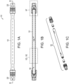
- FIGs. 1A through 1C depict a device in the form of a chromatographic column assembly 10 for separating a sample by chromatography, in accordance with an embodiment.
- Device 10 includes a wall 12 having a wetted surface 14 that is exposed to a mobile phase including the sample during chromatographic separation.
- the wetted surface 14 of the wall includes an alloy material.
- the wetted surface of the wall defines a separation channel 16, as shown.
- the alloy material is limited in an amount of titanium to 0.1 wt%. In some embodiments, the alloy material is limited in an amount of titanium to 0.02 wt%. In some embodiments, the alloy material is limited in an amount of titanium to 0.015 wt%.
- the alloy includes both cobalt and chromium as constituents.
- the alloy material further includes molybdenum as a constituent.
- the alloy material includes the following constituents: 32 wt%-38 wt% cobalt; 32 wt%-38 wt% nickel; 17 wt%-23 wt% chromium; and 7 wt% -13 wt% molybdenum; limited in an amount of titanium to 0.1 wt%; and a remainder being limited to a total of 5 wt%. In some embodiments, the reminder is limited to a total of 3 wt%
- the alloy material includes the following constituents: 34 wt%-36 wt% cobalt; 34 wt%-36 wt% nickel; 19 wt%-21 wt% chromium; and 9 wt% -11 wt% molybdenum; limited in an amount of titanium to 0.05 wt%; and a remainder being limited to a total of 5 wt%. In some embodiments, the reminder is limited to a total of 3 wt%.
- the alloy may be MP35N LT a trademark of SPS Technologies, LLC of Jenkintown, PA, which is comprised of approximately 35 wt% cobalt, 35 wt% nickel, 20 wt% chromium, and 10 wt% molybdenum with less than 0.01 wt% titanium.
- This alloy is known to have strong mechanical properties and can withstand high pressures, such as those used in UHPLC.
- the alloy material is resistant to adsorption of proteins and resistant to adsorption of peptides. In some embodiments the alloy material is resistant to adsorption of histidine-containing peptides. In some embodiments, the alloy material is resistant to adsorption of phosphopeptides.
- chromatographic separation components employing a nickel-cobalt alloy that is limited in an amount of titanium to less than 1 wt% on wetted surfaces exhibit superior performance with respect to resistance to adsorption of biological sample components (e.g., proteins and peptides) as compared to stainless steel components when performing chromatographic separation of biological samples. Further, the inventors determined that decreasing the amount of titanium in the alloy improved the quality of the chromatographic separation. In particular, the inventors determined that a separation column with wetted surfaces of MP35N LT alloy did not show significant peak broadening or peak tailing during analysis of histidine-containing peptides.
- biological sample components e.g., proteins and peptides
- most or all of the thickness of the wall 12 may be made of the alloy.
- FIG. 1D shows a detail view of the wall 12, in which the most or all of the thickness of the wall 12 is made of the alloy material (e.g., MP35N LT), in accordance with some embodiments.
- the alloy material e.g., MP35N LT
- the wall 12 includes a surface portion including the wetted surface and a bulk portion, and the composition of the alloy material of the wetted surface is different than a composition of a material of the bulk portion.
- FIG. 1E shows a detail view, in accordance with another embodiment, in which the wall 12 includes a surface portion 18 and a bulk portion 20.
- the wetted surface 14 is disposed on the surface portion 18 of the alloy material (e.g., MP35N LT) and the bulk portion 20 has a different composition (e.g., stainless steel).
- the material of the bulk portion 20 may be selected for desirable mechanical properties or chemical properties (e.g., strength or corrosion resistance) and/or for issues relating to cost (e.g., the material of the bulk portion may be less expensive than the alloy material).
- Other materials that could be employed for the bulk portion include, but are not limited to stainless steel, titanium, aluminum, carbon fiber composites, PEEK, polyolefins, ceramics, etc.
- the surface portion 18 is deposited on the bulk portion 20. In some embodiments, the surface portion 18 is diffusion bonded to the bulk portion 20. In some embodiments, the surface portion 18 is welded to the bulk portion 20. In some embodiments, the bulk portion 20 is a sleeve around and in contact with the surface portion 18.
- the wetted surface 14 consists of the alloy material. In some embodiments, most of the surface area of the wetted surface is covered by the alloy material. In some embodiments, over 90% of the surface area of the wetted surface is covered by the alloy material. In some embodiments, over 95% of the surface area of the wetted surface is covered by the alloy material. In some embodiments, over 98% of the surface area of the wetted surface is covered by the alloy material. In some embodiments, over 99% of the surface area of the wetted surface is covered by the alloy material.
- the wetted surface 14 of the wall 12 defines a separation channel 16, as shown.
- the alloy is employed in the wall 12 of the separation channel 16 or in at least a surface portion 18 of the wall 12 of the separation channel 16. In some embodiments, the alloy is also employed in one or more wetted surfaces of one or more additional components of the device 12.
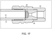
- the device 10 also includes an end fitting 22 and wetted surfaces of the end fitting comprise the alloy material ( see detail view of FIG. 1F ).
- the device 10 also includes a frit 24 and wetted surfaces 25 of the frit 24 comprise the alloy material ( see FIG. 1F ).
- the device 10 further includes a housing 26 that includes the frit 24.
- the detail view of FIG. 1F shows the housing 26 and the frit 24 as part of the column assembly device 10.
- FIGs. 2A-2D show different views of the housing 26.
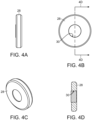
- a device also includes a seal ring 28 and a wetted surface 30 of the seal ring includes the alloy material.
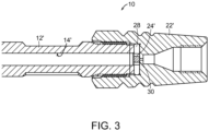
- FIG. 3 depicts a cross-sectional view of an end of a column assembly 10' that includes a wall 12', a wetted surface 14', an end fitting 22', a frit 24' and a seal ring 28 with wetted surface 30.
- FIGs. 4A-4D depict different views of the seal ring 28.
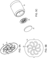
- the device 10 also includes a distributor disk 32 and wetted surfaces 33 of the distributor disk 32 comprise the alloy ( see FIGs. 5A and 5B).
- FIG. 5C shows the distributor disk 32 and a housing assembly 35 with an associated filter or frit 34.
- a housing assembly 35 including the distributor disk 32 and associated filter or frit 34 is located upstream and downstream of the wall of the separation column.
- the chromatographic separation assembly would normally include a stationary phase (not shown) within the separation channel 16.
- all surfaces of the device 10 upstream of and outlet end of the separation channel 16 and configured to be in contact with the mobile phase including the sample during use, excluding the stationary phase comprise the alloy material.
- wetted surfaces of the wall 12, the end fittings 22 and the frit 24 include the alloy material.
- Embodiments include components for use in a device for separating a sample by chromatography.
- the component has a body having a wetted surface exposed to a mobile phase including the sample during chromatographic separation,
- the wetted surface includes an alloy material as described above with respect to the device embodiments.
- the component is the wall 12 having a wetted surface 14 that defines a chromatographic separation channel 16.
- the component is an end fitting 22.
- the component is a frit 24 and the wetted surface is a wetted surface of the frit 24.
- the component is a stationary phase retaining element configured to keep a stationary phase within a separation channel of the device.
- the stationary phase retaining element is a frit 24.
- the frit additionally or alternatively filters solid particulates upstream of a chromatographic separation channel.
- the frit is upstream of a chromatographic separation channel and may be used to keep particulates off of a separate column inlet frit directly upstream of the chromatographic separation channel.
- Embodiments are not limited to chromatographic separation devices with cylindrical columns.
- One of ordinary skill in the art will appreciate that embodiments of chromatographic separation devices may employ other geometries for separation channels.
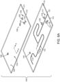
- device 100 shown in FIGs. 6A through 9B has a planar chromatographic chip geometry.
- Device 100 may alternately be described as a component configured for use in a device for separating a sample by chromatography.
- FIG. 6A is an exploded view of the layers of the device 100.
- the device 100 includes a first layer 111 (e.g., a top plate) and a second layer 112 (e.g., a bottom plate).
- the second layer 112 includes grooves 113 and 114, which may be formed by electrochemical micromachining (EMM), also known as electroetching or electrochemical micromachining through a photomask, or milling, that form portions of a chromatographic separation channel.
- EMM electrochemical micromachining
- the first layer 111 includes holes 102, 103, 104, 105, 106, 107, and 108 and slot 109
- the second layer 10b includes holes 115, 116, 117, 118 and 119 and slot 120, which may be made by micro electrical discharge machining (micro-EDM), wire EDM, mechanical drilling, and/or laser drilling.
- Holes 102 and 103 are used as fluidic access ports or vias.
- Holes 104, 105, 106, 107, 115, 116, 117 and 118 are used to attach a fitting at an exterior edge of the device 100 to provide fluidic access on the edge or side 110 of the device 100.
- Holes 108, 119 and slots 109, 120 are used for alignment of the first layer 111 and the second layer 112.
- the first layer 111 is joined to the second layer 112 to form device 100.
- the first layer 111 is joined to the second layer 112 by diffusion bonding or other suitable techniques, such as clamping with a gasket seal.
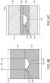
- FIG. 6B schematically depicts a cross-sectional view of the device taken through line A-A of FIG. 6A after the first layer 111 and the second layer 112 have been joined together.
- FIGs. 6A and 6B are not to scale and some relative dimensions are changed for ease of illustration.
- the groove 114 and a surface of the first layer 111 form a channel 122 capable of holding fluids hermetically under high hydraulic pressures.
- groove 113 and the first layer 111 form another portion of channel 122 when the first layer 111 and the second layer 112 are joined.
- a width w of the channel 122 is in a range of 50-500 ⁇ m.
- the first layer 111 and the second layer 112 together form a wall of the device with wetted surface 124.
- the first layer 111, the second layer 202 may be described as together forming a body having a wetted surface 124.
- the wetted surface 124 includes the alloy that includes the following constituents: nickel; and cobalt and/or chromium; and limited in an amount of titanium to 1 wt%. All of the features and variations of the alloy described above with respect to device 10 are also applicable to device 100.
- the first layer 111 and the second layer 112 each include a surface portion and a bulk portion as depicted in FIG. 6C .
- the first layer 111 includes a surface portion 126 including the alloy and a bulk portion 128 of a different material (e.g., stainless steel) and the second layer 112 includes a surface portion 130 including the alloy and a bulk portion 132 of a different material (e.g., stainless steel).
- the bulk portion and the surface portion may be joined together by any suitable techniques, which include, but are not limited to, diffusion bonding, clamping, overmolding, etc.
- the channel 122 is normally packed with a stationary phase (e.g., micrometer sized particles).
- the device 100 may include one or more stationary phase retaining elements at the end or ends of a separation column portion of the channel 122 to prevent the stationary phase from flowing out of the channel 122.
- the stationary phase retaining element is a frit, which may be formed by sintering the stationary phase particles together in some portion of the separation column or by immobilizing some of the stationary phase particles using some other suitable method.
- the stationary phase retaining element is a weir formed in the device 100 by narrowing a portion of the groove 114 formed in the second layer 112 thereby narrowing the corresponding portion of the resulting channel.
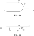
- FIG. 7A-7C schematically depict a weir included in device 100, in accordance with some embodiments.
- Groove 114 narrows at weir 140 forming a narrowed groove 142 and corresponding narrowed channel 144 downstream of the weir.
- the weir 140 has a wetted surface 146.
- FIGs. 8A-8B schematically depict an alternative geometry of a weir included in device 100, in accordance with some embodiments. In FIGs.
- groove 114 narrows and becomes shallower at weir 150 and then widens and deepens to form two channels 122, 152 respectively, connected by a narrower and shallower neck 154.
- the weir 150 has a wetted surface 156.
- a plurality of weirs may be formed at the end of a channel.
- a wetted surface or wetted surfaces of one or more stationary phase retaining elements include the alloy.
- a wetted surface 146 of weir 140 or a wetted surface of weir 150 includes the alloy in some embodiments.
- the device 100 includes an electrospray tip.
- FIGs. 9A and 9D show an embodiment of an end 110' of the device having an integrated electrospray tip 160.
- the electrospray tip 160 is formed by cutting the end 110 of the device 100 (e.g., using EMM and/or EDM) to form the tip geometry.
- Channel 122 narrows at weir 140 to become narrowed channel 142, which exits the device 100 at the electrospray tip 160.
- a wetted surface of the electrospray tip includes the alloy.
- the device 100 further includes one or more integrated valves (not shown), and wetted surfaces of the one or more integrated valves include the alloy material.
- a device may include three layers employing slots to define a channel.
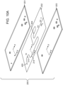
- FIGs. 10A-10C schematically depict a device 200 having a first layer 201, second layer 202, and a third layer 203.
- Device 200 may alternately be described as a component configured for use in a device for separating a sample by chromatography.
- the first layer 201 has similar holes and slots as those described above with respect to first layer 111 of device 100.
- the second layer 202 has similar holes and slots as those described above with respect to second layer 111 of device 100; however, instead of grooves, the second layer 202 has slots 213 and 214.
- the third layer 203 has holes and slots for alignment similar to those described above with respect to second layer 111 of device 100.
- First layer 201, second layer 202 and third layer 203 are joined together.
- the cross-sectional view in FIG. 10B depicts how surfaces of the first layer 201 and the third layer 203 and the slot 214 of the second layer 202 form a hermetically sealed channel 222.
- the first layer 201, the second layer 202 and the third layer 203 can be described as forming a wall of the device 200.
- the first layer 201, the second layer 202 and the third layer 203 can be described as forming a body of the device 200.
- Surfaces of the slot 214 and surfaces of the first layer 201 and third layer 203 form the wetted surfaces 224 of the wall or body, which include the alloy.
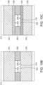
- the first layer 201 and the third layer 203 each include a surface portion and a bulk portion as depicted in FIG. 10C .
- the first layer 201 includes a surface portion 226 including the alloy and a bulk portion 228 of a different material (e.g., stainless steel) and the third layer 203 includes a surface portion 230 including the alloy and a bulk portion 232 of a different material (e.g., stainless steel).
- the bulk portion and the surface portion may be joined together by any suitable techniques, which include, but are not limited to, diffusion bonding, clamping, overmolding, etc.
- the separation device may be part of a microfluidic cartridge.
- the device is configured for low pressure applications.
- the device could be configured for use in solid phase extraction.
- the device is configured for use in supercritical fluid chromatography (SFC).
- the device is configured for use in gas chromatography.
- Low pressure applications refers to applications in which the pressure in the device falls within a range of atmospheric pressure to 6.89MPa (1000 psi).
- the device is configured to withstand pressures used in high performance liquid chromatography.
- high performance liquid chromatography refers to liquid chromatography in which the mobile phase is subjected to pressures of between 6.89 to 41.37 MPa (1,000 and 6,000 psi).
- the device is configured to withstand pressures used in ultra-high performance liquid chromatography.
- ultra high performance liquid chromatography refers to liquid chromatography in which the mobile phase is subjected to pressures of greater than 41.37 MPa (6,000 psi).
- the device is configured to withstand pressures of 41.37 to 103.42 MPa (6,000 to 15,000 psi) during use. In some embodiments, the device is configured to withstand pressures of 41.37 to 124.1 MPa (6,000 psi to 18,000 psi) during use. In some embodiments, the device is configured to withstand pressures of 103.42 to 137.89 MPa (15,000 to 20,000 psi) during use. In some embodiments, the device is configured to withstand pressures of 103.42 to 344.74 MPa (20,000 psi to 50,000 psi) during use.
- a width or diameter of a separation channel of a device or component falls in a range of 10 ⁇ m to 25 mm. In some embodiments, a width or diameter of a separation channel of a device or component falls in a range of 20 ⁇ m to 7.8 mm. For a prep column, a width or diameter may be as large as 100 mm. In some embodiments, such as a microfluidic device or a microfluidic component, a width or diameter of a separation column may be in the range of 20 ⁇ m to 500 ⁇ m.
- the use of the alloy for a wetted surface of a device or component is particularly beneficial in a microfluidic system, as opposed to using surface-treated stainless steel for wetted surfaces because of the difficulties associated with accomplishing effective surface treatment in microfluidic systems.
- the use of the alloy for a wetted surface of a device or component is beneficial, as compared to using surface treated fused silica because it is easier to manufacture separation columns from metals such as the alloy than from silica, and because the silanols of the fused silica wetted surface can interact with proteins and peptides by ion exchange.
- a chromatographic separation device 10 including a separation channel 16 is provided.
- the separation channel 16 has wetted surfaces 14 including an alloy material.
- the alloy material includes the following constituents nickel; and cobalt and/or chromium; and limited in an amount of titanium to 1 wt%. Other features and aspects of the alloy material in accordance with various embodiments are described above.
- a mobile phase is flowed carrying the sample into and through the separation channel 16, thereby performing chromatographic separation on the sample.
- the method further includes detecting components of the sample.
- the sample includes proteins and the proteins in the sample are separated and detected.
- the sample includes peptides and the peptides in the sample are separated and detected. In some embodiments, the sample includes histidine-containing peptides and the histidine-containing peptides in the sample are separated and detected. In some embodiments, the sample includes phosphopeptides and the phosphopeptides in the sample are separated and detected. In some embodiments, the sample includes one or more of peptides or proteins and the one or more proteins or peptides in the sample are separated and detected with a U.S. Pharmacopeia (USP) tailing factor of less than 1.3.
- USP U.S. Pharmacopeia
- separation devices having a stationary phase including an alloy material described herein.
- separation devices with a stationary phase including an alloy material described herein include, for example, chromatographic columns; thin layer plates; filtration membranes; sample cleanup devices and microtiter plates; packings for HPLC columns; solid phase extraction (SPE) devices; ion-exchange chromatography devices; magnetic beads; affinity chromatographic and SPE sorbents; sequestering reagents; solid supports for combinatorial chemistry; solid supports for oligosaccharide, polypeptides, and/or oligonucleotide synthesis; solid supported biological assays; capillary biological assay devices for mass spectrometry; templates for controlled large pore polymer films; capillary chromatography devices; electrokinetic pump packing materials; packing materials for microfluidic devices; polymer additives; catalysis supports; and packings materials for microchip separation devices.
- alloy materials as described herein can be packed into preparatory, microbore, capillary, and microfluidic devices.
- a solid stationary phase in a device includes the alloy materials as described herein.
- surfaces of a solid stationary phase in a device include the alloy materials described herein.
- both the solid phase and a wetted surface of a wall of the device include an alloy or alloys as described herein.
- Embodiments can be used for all modes of chromatography. Separation modes include but are not limited to reversed phase, normal phase, size exclusion, ion exchange, affinity, hydrophobic interaction and hydrophilic interaction.
- Separation modes include but are not limited to reversed phase, normal phase, size exclusion, ion exchange, affinity, hydrophobic interaction and hydrophilic interaction.
- the alloys described herein can be employed in sample preparation devices for all the above modes.
- the IMER includes a wall defining a chamber having an inlet and an outlet and a solid stationary phase covalently linked to an enzyme within the chamber.
- a liquid sample including a polymer and an analyte flows into the chamber through the inlet, interacts with the immobilized enzyme and flows out of the chamber through the outlet.
- the solid stationary phase of the IMER includes an alloy described herein.
- a wetted surface of the wall of the chamber i.e., a surface that is in contact with the liquid sample during use) includes an alloy described herein.
- both a wetted surface of the wall of the chamber and the solid stationary phase of the IMER include one or more of the alloys described herein.
- the IMER device includes additional components or fittings and wetted surfaces of one or more of the additional components or fittings include one or more alloys described herein.
- the IMERs are suitable for operation under pressures in the range of about 17.24 to 241.32 MPa (2,500 to 35,000 psi). In some embodiments, the IMERs are suitable for operation under pressures in the range of 55.16 to 103.42 MPa (8,000 to 15,000 psi). Additional details regarding IMER devices and systems are provided in U.S. Patent Application Publication No.
- the chamber of the IMER may have a configuration similar to that of chromatographic separation devices described herein.
- chromatographic separation devices described herein.
- One of ordinary skill in the art in view of the present disclosure will appreciate that the drawings and description herein regarding devices, columns and components for chromatographic separation also applies, in large part to IMERs.
- a structure described herein as a separation column or a separation channel may also or alternatively be viewed and described as a chamber in which a stationary phase can be disposed for an IMER.
- Enzymes that could be immobilized on the stationary phase in an IMER include, but are not limited to: pepsin, protease, cellulose, lipase, amylase, glucoamylase, glucose isomerase, xylanase, phtase, arabinanase, polygalacturonase, hydrolase, chymosin, urease, pectinase, beta-gluconase, ligase, glycosidase, polymerase, phosphatase, kinase, ceramidase.
- the enzyme is trypsin, PNGase F, pepsin, chymotrypsin, peptidase, bromelain, papain, IdeS, or IdeZ, or mixtures thereof.
- the stationary phase includes immobilized affinity reagents, which include, but are not limited to: Protein G, Lambda, Kappa, Protein Y, Protein L, aptamers, affimers, amyloids, lectins, or activated resins for user generated affinity phases such as streptavidin and epoxy.
- the target molecules of the immobilized affinity reagents include, but are not limited to: proteins, IgG, IgM, insulin, peptides, small molecules, toxins, afflatoxins, mycotoxins, citrinin, deoxynivalenol, vomitoxin, fumonisin, ochratoxin, zearalenone, fusarium, or mixtures thereof.
- the immobilized affinity immobilized affinity reagents or the target molecules of immobilized affinity reagents are incorporated into a technology platform such as the Stable Isotope Standards and Capture by Anti-Peptide Antibodies (SISCAPA) affinity workflow from SISCAPA Assay Technologies Inc.
- SISCAPA Stable Isotope Standards and Capture by Anti-Peptide Antibodies
- the stationary phase is modified to include one or more immobilized affinity and immobilized enzyme materials.
- a column for a separation device or for an IMER has an inner diameter of 1.0 mm, 2.1 mm, 3.0 mm, 4.6 mm, 10 mm, 19 mm, 30 mm ID, or a diameter there between. In some embodiments, a column for a separation device or for an IMER has an inner diameter falling in a range of 0.5-100 mm.
- a column for a separation device or for an IMER has a length of 5 mm, 10 mm, 30 mm, 50 mm, 75 mm, 100 mm, 150 mm, 200 mm, 300 mm 500 mm, 1000 mm, 2000 mm length, or a length falling there between.
- a component for a separation device or for an IMER is compatible with or configured to be used with 1 mm ID column hardware, 2.1 mm ID column hardware, 3.0 mm ID column hardware, 4.6 mm I D column hardware, 10 mm ID column hardware, 19 mm ID column hardware, 30 mm ID column hardware, 0.5-100 mm ID column hardware, planar geometry chromatographic separation devices, diffusion-bonded separation devices, or microfluidic cartridges,
- Incorporating the alloy materials described herein into devices may improve the lifetimes of the devices due to the improved corrosion resistance of the alloy material as compared with other materials normally used on surfaces of such devices.
- Embodiments of devices that have a stationary phase including an alloy as described herein may exhibit improved lifetimes.
- Embodiments of devices that have one or more wetted surfaces that include an alloy as described herein may exhibit improved lifetimes.
- kits including a device or one or more components of a device as described herein, and instructions for use.
- the instructions are for use with a separation device, e.g., chromatographic columns, thin layer plates, filtration membranes, sample cleanup devices, solid phase extraction device, microfluidic device, and microtiter plates.
- the instructions are for use with an immobilized enzymatic reactor device.
- the inventors performed chromatographic separation on samples including peptides to compare the performance of conventional stainless steel and silica separation columns to example separation columns.
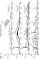
- FIG. 11 includes chromatograms of a tryptic digest of a sample of enolase analyzed with a conventional stainless steel separation column.
- Chromatogram 310 shows significant peak broadening for an extracted mass 312 of peptide 1 in the sample.
- Chromatogram 314 shows significant peak broadening for an extracted mass 316 of peptide 2 in the sample.
- Chromatogram 318 shows even more significant peak broadening for an extracted mass 320 of peptide 3 in the sample.
- Chromatogram 322 of the total ion current shows the broadened peaks 312, 316, 320 for peptide 1, peptide 2 and peptide 3 respectively.
- the peaks for peptides 1, 2 and 3 show relatively low signal to noise ratio in addition to significant broadening.
- chromatograms illustrate a problem with the use of a stainless steel column for samples including peptides.
- some peptides such as histidine-containing peptides do not appear in the chromatogram or have extremely broad peak shape, often observed with significant peak tailing.
- the peptides are tryptic digests of enolase, which are included in the MASSPREP Enolase Digest with Phosphopeptides Mix available from Waters Corporation of Milford, MA.
- Peptide 1 is T3 (sequence WLTGPQLADLYHSLMK)
- Peptide 2 is T44 (sequence AAQDSFAAGWGVMVSHR)
- Peptide 3 is T51-52 (sequence IEEELGDNAVFAGENFHHGDKL).
- MASSPREP ENOLASE DIGEST WITH PHOSPHOPEPTIDES MIX - Care and Use Manual by Waters Corporation, which is available at http://www.waters.com/webassets/cms/support/docs/71500 1713 .pdf ..
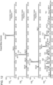
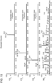
- FIG. 12 includes chromatograms of a tryptic digest of the same sample of enolase analyzed with a column constructed with fused silica tubing, specifically the NANOEASE column from Waters Corporation of Milford, Massachusetts.
- chromatogram 330 shows a narrow peak and high signal to noise ratio for the extracted mass 312 of peptide 1 in the sample.
- chromatogram 334 shows a narrow peak and high signal to noise ratio for the extracted mass 316 of peptide 2 in the sample.
- chromatogram 338 shows a narrow peak and high signal to noise ratio for the extracted mass 320 of peptide 3 in the sample.
- Chromatogram 340 shows the total ion current and the excellent signal to noise ratio of peaks 312, 316, 320 for peptide 1, peptide 2 and peptide 3 respectively.
- the contrast between the chromatograms in FIG. 11 and FIG. 12 illustrates how poor the stainless steel column performed for separation of these three peptides.
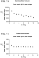
- FIG. 13 shows how the peak width of a peptide significantly changes over 10 injections in a stainless steel column, demonstrating that the stainless steel column requires substantial conditioning to obtain consistent results. Such conditioning wastes sample and experimental time.
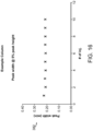
- graph 360 of FIG. 14 demonstrates how the peak width for the peptide is consistent from injections 2 through 10 indicating that the fused silica column does not need significant conditioning.
- fused silica may be an undesirable material for many applications due to the difficulty in making devices and components from fused silica as compared with making devices and components from a metal material.
- Some surface modifications can be made in a stainless steel separation column for better performance with peptide containing samples such as surface passivation of wetted surfaces or coatings that can be applied to wetted surfaces (e.g., creating an iron-deficient and chromium-rich surface or coating with polymers); however, such surface modifications and coatings can fail if the surface or coating is damaged during use. Further, such surface treatments and coatings are difficult to accomplish in microscale devices. Embodiments employing the alloys described herein avoid the need for surface treatments or coatings on wetted surfaces thereby reducing complexity in manufacturing.
- An example separation column was constructed using a nickel-cobalt alloy material, specifically, MP35N LT, for the column hardware. This alloy has approximately 35 wt% cobalt, 35 wt% nickel, 20 wt% chromium, and 10 wt% molybdenum with less than 0.01 wt% titanium.
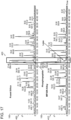
- the example separation column was used for separation and detection of the enolase peptide sample, with the results shown in FIGs. 15 and 16 .
- chromatogram 370 for the example column shows a narrow peak and high signal to noise ratio for the extracted mass 312 of peptide 1 in the sample.
- chromatogram 374 for the example column shows a narrow peak and high signal to noise ratio for the extracted mass 316 of peptide 2 in the sample.
- chromatogram 378 for the example column shows a narrow peak and high signal to noise ratio for the extracted mass 320 of peptide 3 in the sample.
- Chromatogram 380 for the example column shows the total ion current and the excellent signal to noise ratio for peaks 312, 316, 320 for peptide 1, peptide 2 and peptide 3, respectively.
- the contrast between the graphs in FIGs. 11 and 15 demonstrates the superior performance of the example column as compared to the stainless steel column for separation and detection of these three peptides. Peptides whose peaks were broadened or missing in the stainless steel column data are present, narrow, and have good signal to noise ratio in the example column data.
- Comparison of FIG. 15 for the example column and FIG. 12 for the fused silica column shows that the example column performed at least as well as fused silica for separation and detection of the three peptides.
- FIG. 16 includes a graph 382 of peptide peak width for subsequent sample injections in the example column. As shown, there was very little peak width variation for the second to tenth sample injections demonstrating that the example column did not need conditioning, unlike the stainless steel column. Thus, use of the example column would save sample and time by avoiding the need for column conditioning, relative to use of the stainless steel column.
- nickel ions and cobalt ions are known to chelate certain types of peptides or proteins by metal chelation interaction chromatography, which would indicate that a nickel-cobalt alloy may not be desirable for reducing interactions with peptides and proteins.
- alloys described herein are also expected to perform well in applications such as ion-exchange separations, size exclusion chromatography (SEC), and other applications where high buffer and salt concentrations are commonly used.
- SEC size exclusion chromatography
- columns for these classes of separations commonly employ materials such as glass and PEEK, both of which can limit the design pressure of the columns and/or significantly affect the cost and complexity of the column design.
- the inventors also explored nickel-cobalt alloys having higher levels of titanium.
- a sample of tubing material was placed in line with a separation column and was exposed to the pressure gradient and to the sample during sample separation.
- the reference tubing material was fused silica and the tubing material being evaluated was MP35N, a trademarked alloy of SPS Technologies, LLC of Jenkintown, PA, which includes 35 wt% cobalt, 35 wt% nickel, 20 wt% chromium, 10 wt% molybdenum, and about 1 wt% titanium FIG.
- LC/MS chromatograms for a sample including enolase peptides for both the fused silica tubing (chromatogram 400) and for the MP35N tubing (chromatogram 410).
- chromatogram 400 a sample including enolase peptides for both the fused silica tubing
- chromatogram 410 for the MP35N tubing
- a phosphopeptide that was clearly present in the chromatogram 400 produced with the system including the fused silica tube was absent from the chromatogram 410 produced with the system including the MP35N tube as indicated by box 412.
- the inventors determined that the adsorption of peptides is sensitive to titanium levels in the alloy and that titanium levels in the nickel-cobalt alloy should be less than 1 wt% titanium.
- An immobilized enzymatic reactor is prepared by packing a stationary phase of porous particles having immobilized pepsin on the surface of the particles in UPLC column hardware (2.1 ⁇ 30 mm) made from MP35N.
- the packed MP35N column was used with an ultra performance liquid chromatography system, specifically, the NANOACQUITY ULTRAPERFORMANCE LC system from Waters Corp. of Milford, MA. Further details regarding preparing and using an IMER with a column made from a different material appear in U.S. Patent Application Publication No. 2014/0162298, published June 12, 2014 and entitled "Immobilized Enzymatic Reactor,".
- the packed MP35N column withstands elevated pressures, exhibits good digestive performance, and exhibits decreased adsorptive losses of peptides that are generated in the on-line digestion as compared with traditional stainless steel hardware.
- ion-exchange chromatography ion-exchange chromatography
- ion-chromatography Size Exclusion Chromatography
- Reversed-Phase Chromatographic Hydrophobic Interaction Chromatography
- Hydrophilic interaction chromatography Gel Permeation chromatography
- Normal-Phase Chromatography Chiral Chromatography
- Supercritical Fluid Chromatography and Subcritical Fluid Chromatography.
- the avoidance of corrosion in chromatographic hardware is especially important in ion-exchange chromatography. To avoid corrosion when exposed to mobile phases that are high or low pH, and contain elevated salt, many commercial suppliers of ion-exchange columns use non-metallic hardware, such as plastic columns and in particular PEEK chromatographic hardware.
- plastic or PEEK chromatographic hardware is not suitable for ultra performance liquid chromatography. It is difficult to efficiently pack chromatographic media under the required pressures for ultra performance liquid chromatography when the chromatographic hardware includes PEEK or is plastic lined steel, and the use conditions for ultra performance liquid chromatography are above the normal operating range for plastic or PEEK chromatographic hardware.
- MP35N LT nickel-cobalt alloy material
- chromatographic column hardware tubes 2.1 ⁇ 100 mm
- an acid 20mM 1,4-dimethylpiperazine buffer with 1M NaCl and 0.05% sodium azide, adjusted to pH 3.5 using dilute hydrochloric acid
- MP35N LT is a low titanium grade (less than 0.01 wt% Ti) of MP35N.
- the tubes were emptied into plastic vials.
- the two samples along with a control acid solution were analyzed for metals content (ICP-MS, VHG Labs, Manchester NH, uncertainty estimated at +/-10%). The results of these studies are shown in the table below.
- Acid control sample Acid Stored in Stainless Steel Column Acid Stored in MP35N LT Column Iron (ppb) ⁇ 100 3861 359 Cobalt (ppb) ⁇ 20 1559 Chromium (ppb) ⁇ 20 672 325 Nickel (ppb) ⁇ 10 460 1001 Molybdenum (ppb) ⁇ 10 ⁇ 10 ⁇ 10 Manganese (ppb) ⁇ 10 92 ⁇ 10 Total Metals (ppb) 5115 3264
- low titanium nickel-cobalt alloys such as MP35N LT
- MP35N LT which are mechanically strong enough to be used for ultra performance liquid chromatography
- chromatographic separations including (but not limited to): ion-exchange chromatography, ion-chromatography, Size Exclusion Chromatography, Reversed-Phase Chromatographic, Hydrophobic Interaction Chromatography, Hydrophilic interaction chromatography, Gel Permeation chromatography, Normal-Phase Chromatography, Chiral Chromatography, Supercritical Fluid Chromatography, and Subcritical Fluid Chromatography.
- the use of MP35N LT chromatographic hardware is especially suited for the use in ion-exchange chromatography, and ultra performance ion-exchange liquid chromatography.
Landscapes
- Chemical & Material Sciences (AREA)
- Health & Medical Sciences (AREA)
- Analytical Chemistry (AREA)
- Life Sciences & Earth Sciences (AREA)
- Engineering & Computer Science (AREA)
- General Health & Medical Sciences (AREA)
- Biochemistry (AREA)
- Immunology (AREA)
- Chemical Kinetics & Catalysis (AREA)
- Physics & Mathematics (AREA)
- General Physics & Mathematics (AREA)
- Pathology (AREA)
- Wood Science & Technology (AREA)
- Zoology (AREA)
- Bioinformatics & Cheminformatics (AREA)
- Organic Chemistry (AREA)
- Oil, Petroleum & Natural Gas (AREA)
- General Chemical & Material Sciences (AREA)
- Genetics & Genomics (AREA)
- Biotechnology (AREA)
- General Engineering & Computer Science (AREA)
- Sustainable Development (AREA)
- Microbiology (AREA)
- Biomedical Technology (AREA)
- Nanotechnology (AREA)
- Molecular Biology (AREA)
- Clinical Laboratory Science (AREA)
- Treatment Of Liquids With Adsorbents In General (AREA)
Claims (9)
- Vorrichtung zum Trennen einer Probe durch Chromatografie, die Vorrichtung umfassend:
eine Wand (12), die eine benetzte Oberfläche (14) aufweist, die während einer chromatografischen Trennung einer mobilen Phase, einschließlich der Probe, ausgesetzt ist, wobei die benetzte Oberfläche (14) der Wand ein Legierungsmaterial, umfassend die folgenden Bestandteile, einschließt:zu 32 Gew.-%-38 Gew.-% Kobalt;zu 32 Gew.-%-38 Gew.-% Nickel;zu 17 Gew.-%-23 Gew.-% Chrom; undzu 7 Gew.-%-13 Gew.-% Molybdän; undwobei ein Rest auf insgesamt 5 Gew.-% begrenzt ist und in einer Titanmenge auf 0,1 Gew.-% begrenzt ist. - Vorrichtung nach Anspruch 1, wobei die Wand (12) einen Oberflächenabschnitt (18), einschließlich der benetzten Oberfläche, (14) und einen Hauptabschnitt (20) umfasst, und wobei sich die Zusammensetzung des Legierungsmaterials der benetzten Oberfläche (14) von einer Zusammensetzung eines Materials des Hauptabschnitts (20) unterscheidet.
- Vorrichtung nach Anspruch 2, wobei der Oberflächenabschnitt (18) mit dem Hauptabschnitt (20) durch Diffusionbonden verbunden ist.
- Vorrichtung nach Anspruch 1, wobei die benetzte Oberfläche (14) der Wand (12) einen Trennkanal (122) definiert.
- Vorrichtung nach Anspruch 4, ferner umfassend eine Fritte (24), wobei benetzte Oberflächen (14) der Fritte (24) das Legierungsmaterial umfassen.
- Vorrichtung nach Anspruch 4, ferner umfassend ein Wehr (150), wobei benetzte Oberflächen (14) des Wehrs (150) das Legierungsmaterial umfassen.
- Vorrichtung nach Anspruch 4, wobei die Vorrichtung eine mikrofluidische Vorrichtung ist und die Breite oder der Durchmesser des Trennkanals (122) in einem Bereich von 20 µm bis 500 µm liegt.
- Vorrichtung nach Anspruch 4, wobei die Vorrichtung zwei oder mehr Lagen des Legierungsmaterials umfasst, wobei ein Abschnitt jeder Lage einen Abschnitt der Wand (12) bildet,
wobei die zwei oder mehr Lagen an einer Schnittstelle durch Diffusionbonden verbunden sind, wobei sich mindestens ein Abschnitt des Trennkanals (122) entlang der Schnittstelle erstreckt - Vorrichtung nach Anspruch 4, wobei die Vorrichtung zwei oder mehr Lagen umfasst, jede Lage einschließlich einer Schicht des Legierungsmaterials, wobei jede Lage einen Abschnitt der Wand (12) bildet, wobei die Schicht des Legierungsmaterials der Lage die benetzte Oberfläche für den Abschnitt der Wand bildet, wobei die Schichten des Legierungsmaterials der zwei oder mehr Lagen an einer Schnittstelle durch Diffusionbonden verbunden sind, wobei sich mindestens ein Abschnitt des Trennkanals (122) entlang der Schnittstelle erstreckt.
Applications Claiming Priority (2)
| Application Number | Priority Date | Filing Date | Title |
|---|---|---|---|
| US201562204769P | 2015-08-13 | 2015-08-13 | |
| PCT/US2016/046752 WO2017027796A1 (en) | 2015-08-13 | 2016-08-12 | Nickel-cobalt alloy material devices and components |
Publications (3)
| Publication Number | Publication Date |
|---|---|
| EP3334508A1 EP3334508A1 (de) | 2018-06-20 |
| EP3334508A4 EP3334508A4 (de) | 2019-04-10 |
| EP3334508B1 true EP3334508B1 (de) | 2024-12-18 |
Family
ID=57983851
Family Applications (1)
| Application Number | Title | Priority Date | Filing Date |
|---|---|---|---|
| EP16835971.9A Active EP3334508B1 (de) | 2015-08-13 | 2016-08-12 | Vorrichtungen und komponenten aus legierungsmaterial |
Country Status (4)
| Country | Link |
|---|---|
| US (1) | US11511213B2 (de) |
| EP (1) | EP3334508B1 (de) |
| CN (1) | CN108348818B (de) |
| WO (1) | WO2017027796A1 (de) |
Families Citing this family (5)
| Publication number | Priority date | Publication date | Assignee | Title |
|---|---|---|---|---|
| US12180581B2 (en) | 2017-09-18 | 2024-12-31 | Waters Technologies Corporation | Use of vapor deposition coated flow paths for improved chromatography of metal interacting analytes |
| US12181452B2 (en) | 2017-09-18 | 2024-12-31 | Waters Technologies Corporation | Use of vapor deposition coated flow paths for improved chromatography of metal interacting analytes |
| US11918936B2 (en) | 2020-01-17 | 2024-03-05 | Waters Technologies Corporation | Performance and dynamic range for oligonucleotide bioanalysis through reduction of non specific binding |
| WO2021211856A1 (en) * | 2020-04-15 | 2021-10-21 | Waters Technologies Corporation | Sec performance enhancing conditioning and storage solvents containing low levels of buffer and salt |
| US12352734B2 (en) | 2020-09-24 | 2025-07-08 | Waters Technologies Corporation | Chromatographic hardware improvements for separation of reactive molecules |
Family Cites Families (35)
| Publication number | Priority date | Publication date | Assignee | Title |
|---|---|---|---|---|
| US3878092A (en) * | 1973-03-12 | 1975-04-15 | Phillips Petroleum Co | Chromatographic colums |
| DK165090D0 (da) | 1990-07-09 | 1990-07-09 | Kem En Tec As | Konglomererede partikler |
| US7473244B2 (en) * | 2000-06-02 | 2009-01-06 | The University Of Utah Research Foundation | Active needle devices with integrated functionality |
| WO2002018929A2 (en) * | 2000-09-01 | 2002-03-07 | Cabot Corporation | Chromatography and other adsorptions using modified carbon adsorbents |
| CA2423178C (en) * | 2000-09-26 | 2013-04-16 | Bayer Aktiengesellschaft | Adsorption container and iron oxide adsorber |
| US7220390B2 (en) | 2003-05-16 | 2007-05-22 | Velocys, Inc. | Microchannel with internal fin support for catalyst or sorption medium |
| US20070054345A1 (en) | 2004-05-19 | 2007-03-08 | Hunter Christie L | Expression quantification using mass spectrometry |
| US20060183238A1 (en) | 2005-02-09 | 2006-08-17 | Applera Corporation | Amine-containing compound analysis methods |
| TW200740709A (en) | 2005-07-26 | 2007-11-01 | Dro Biosystems S L | Static support bed for purification, separation, detection, modification and/or immobilization of target entities and method using thereof |
| WO2007044935A2 (en) | 2005-10-13 | 2007-04-19 | Applera Corporation | Methods for the development of a biomolecule assay |
| US8097425B2 (en) | 2006-03-10 | 2012-01-17 | Tethys Bioscience, Inc. | Multiplex protein fractionation |
| EP1795264B1 (de) * | 2006-07-06 | 2012-08-22 | Agilent Technologies, Inc. | Flüssigkeitsabweisende Spitze |
| WO2008036583A2 (en) * | 2006-09-19 | 2008-03-27 | Waters Investments Limited | Tubing and method for manufacture |
| EP2089532A4 (de) | 2006-12-01 | 2010-02-17 | Cedars Sinai Medical Center | Positivauswahl von serumsproteinen zur proteom-analyse |
| US7807172B2 (en) | 2007-06-13 | 2010-10-05 | University Of Washington | Methods and compositions for detecting thyroglobulin in a biological sample |
| JP5544640B2 (ja) | 2007-10-08 | 2014-07-09 | コリア リサーチ インスティチュート オブ バイオサイエンス アンド バイオテクノロジー | 特定レクチン沈殿法を用いて糖タンパク質を同定する方法 |
| US20100105570A1 (en) | 2008-10-09 | 2010-04-29 | Alliance For Sustainable Energy, Llc | Multi-Chamber Pretreatment Reactor for High Throughput Screening of Biomass |
| KR100937720B1 (ko) | 2009-04-20 | 2010-01-20 | 전남대학교산학협력단 | CFH 또는 ApoH를 급성골수성백혈병 관해 진단용 생화학적 마커로 사용하는 방법 |
| US20120132794A1 (en) * | 2009-04-20 | 2012-05-31 | Waters Technologies Corporation | Apparatus And Components Thereof For Liquid Chromatography |
| KR20100117173A (ko) | 2009-04-24 | 2010-11-03 | 쓰리엠 이노베이티브 프로퍼티즈 캄파니 | 전기화학적 바이오센서용 전극 스트립 및 그 제조방법 |
| US8471198B2 (en) | 2009-05-13 | 2013-06-25 | Micromass Uk Limited | Mass spectrometer sampling cone with coating |
| FR2946147B1 (fr) | 2009-05-29 | 2012-08-31 | Biomerieux Sa | Nouveau procede de quantification de proteines par spectrometrie de masse |
| FR2950697B1 (fr) | 2009-09-25 | 2011-12-09 | Biomerieux Sa | Procede de detection de molecules par spectrometrie de masse |
| KR101143891B1 (ko) | 2009-12-29 | 2012-05-11 | 한국기초과학지원연구원 | 단백질의 비정상적인 당쇄화를 이용하는 암진단 마커 |
| US8455202B2 (en) | 2010-03-10 | 2013-06-04 | Perfinity Biosciences, Inc. | Affinity selector based recognition and quantification system and method for multiple analytes in a single analysis |
| US9274124B2 (en) | 2010-03-15 | 2016-03-01 | Anderson Forschung Group, Inc. | Mass spectrometric assays for peptides |
| JP5926723B2 (ja) * | 2010-03-26 | 2016-05-25 | ウオーターズ・テクノロジーズ・コーポレイシヨン | 拡散結合され表面改質された構成要素を有するクロマトグラフィ装置 |
| JP6189752B2 (ja) | 2011-02-16 | 2017-08-30 | ウオーターズ・テクノロジーズ・コーポレイシヨン | 固定化酵素反応器 |
| US8574860B2 (en) | 2011-05-09 | 2013-11-05 | University Health Network | Biomarkers for the detection and screening of down syndrome |
| JP5682986B2 (ja) | 2011-07-22 | 2015-03-11 | 国立大学法人東北大学 | 質量分析における安定同位体標識標的ペプチド断片の作製方法 |
| WO2013078222A1 (en) | 2011-11-23 | 2013-05-30 | Quest Diagnostics Investments Incorporated | Kisspeptin-54 detection by tandem mass spectrometry |
| EP2809415B1 (de) * | 2012-01-30 | 2025-07-16 | Repligen Corporation | Verfahren zur herstellung und packung von chromatographiesäulen |
| WO2013173627A1 (en) | 2012-05-16 | 2013-11-21 | Expression Pathology, Inc. | Srm/mrm assay for subtyping lung histology |
| US9447304B2 (en) | 2013-03-14 | 2016-09-20 | W. L. Gore & Associates, Inc. | Coating for a surface |
| CN108176078A (zh) * | 2013-06-11 | 2018-06-19 | 沃特世科技公司 | 色谱柱和分离装置及其用途 |
-
2016
- 2016-08-12 CN CN201680060189.0A patent/CN108348818B/zh active Active
- 2016-08-12 US US15/752,121 patent/US11511213B2/en active Active
- 2016-08-12 WO PCT/US2016/046752 patent/WO2017027796A1/en not_active Ceased
- 2016-08-12 EP EP16835971.9A patent/EP3334508B1/de active Active
Also Published As
| Publication number | Publication date |
|---|---|
| US20180236379A1 (en) | 2018-08-23 |
| EP3334508A1 (de) | 2018-06-20 |
| US11511213B2 (en) | 2022-11-29 |
| WO2017027796A1 (en) | 2017-02-16 |
| CN108348818A (zh) | 2018-07-31 |
| EP3334508A4 (de) | 2019-04-10 |
| CN108348818B (zh) | 2021-05-28 |
Similar Documents
| Publication | Publication Date | Title |
|---|---|---|
| EP3334508B1 (de) | Vorrichtungen und komponenten aus legierungsmaterial | |
| US12410390B2 (en) | Factory-on-a-chip for production of biologically derived medicines/biopharmaceuticals/biologics/biotherapeutics | |
| US5482628A (en) | Column for liquid chromatography | |
| US9562879B2 (en) | Pipe containing a metal casing with a plastics material inlay for use in low and high pressure applications, in particular as an HPLC column | |
| US20120067823A1 (en) | Liquid chromatography component | |
| US9724621B2 (en) | Device, apparatus and method for performing separations | |
| US20070138076A1 (en) | Devices and methods for microfluidic chromatography | |
| JP4909897B2 (ja) | 分離を実施するデバイス、方法、および装置 | |
| Fekete | Defining material used in biopharmaceutical analysis | |
| US20100018928A1 (en) | Device for performing separations and methods of making and using same | |
| AU2019210710B2 (en) | Capillary fitting | |
| JP3890077B2 (ja) | 液体クロマトグラフィー用フィルター、液体クロマトグラフィー用カラム及びヘモグロビン類の測定方法 | |
| JP3857439B2 (ja) | 液体クロマトグラフィー用フィルター、液体クロマトグラフィー用カラム及びヘモグロビン類の測定方法 | |
| Gorja et al. | Review on Ultra Performance Liquid Chromatography | |
| Fehrenbach et al. | Materials in HPLC and UHPLC–What to Use for Which Purpose | |
| Szumski et al. | Miniaturization in Separation Techniques | |
| EP3856383B1 (de) | Säule mit kompressionsbegrenzter anordnung | |
| JP6897052B2 (ja) | カラムフィルター | |
| Wong | Automation, Direct-Sample Analysis, and Microcolumn Liquid Chromatography | |
| WO2017203683A1 (ja) | 分離媒体及びその製造方法、分離カラム及びその分離カラムを用いた液体クロマトグラフ |
Legal Events
| Date | Code | Title | Description |
|---|---|---|---|
| STAA | Information on the status of an ep patent application or granted ep patent |
Free format text: STATUS: THE INTERNATIONAL PUBLICATION HAS BEEN MADE |
|
| PUAI | Public reference made under article 153(3) epc to a published international application that has entered the european phase |
Free format text: ORIGINAL CODE: 0009012 |
|
| STAA | Information on the status of an ep patent application or granted ep patent |
Free format text: STATUS: REQUEST FOR EXAMINATION WAS MADE |
|
| 17P | Request for examination filed |
Effective date: 20180208 |
|
| AK | Designated contracting states |
Kind code of ref document: A1 Designated state(s): AL AT BE BG CH CY CZ DE DK EE ES FI FR GB GR HR HU IE IS IT LI LT LU LV MC MK MT NL NO PL PT RO RS SE SI SK SM TR |
|
| AX | Request for extension of the european patent |
Extension state: BA ME |
|
| DAV | Request for validation of the european patent (deleted) | ||
| DAX | Request for extension of the european patent (deleted) | ||
| A4 | Supplementary search report drawn up and despatched |
Effective date: 20190308 |
|
| RIC1 | Information provided on ipc code assigned before grant |
Ipc: B01D 53/02 20060101ALI20190304BHEP Ipc: G01N 30/60 20060101ALI20190304BHEP Ipc: B01D 15/08 20060101AFI20190304BHEP |
|
| STAA | Information on the status of an ep patent application or granted ep patent |
Free format text: STATUS: EXAMINATION IS IN PROGRESS |
|
| 17Q | First examination report despatched |
Effective date: 20200810 |
|
| GRAP | Despatch of communication of intention to grant a patent |
Free format text: ORIGINAL CODE: EPIDOSNIGR1 |
|
| STAA | Information on the status of an ep patent application or granted ep patent |
Free format text: STATUS: GRANT OF PATENT IS INTENDED |
|
| INTG | Intention to grant announced |
Effective date: 20240715 |
|
| GRAS | Grant fee paid |
Free format text: ORIGINAL CODE: EPIDOSNIGR3 |
|
| GRAA | (expected) grant |
Free format text: ORIGINAL CODE: 0009210 |
|
| STAA | Information on the status of an ep patent application or granted ep patent |
Free format text: STATUS: THE PATENT HAS BEEN GRANTED |
|
| AK | Designated contracting states |
Kind code of ref document: B1 Designated state(s): AL AT BE BG CH CY CZ DE DK EE ES FI FR GB GR HR HU IE IS IT LI LT LU LV MC MK MT NL NO PL PT RO RS SE SI SK SM TR |
|
| REG | Reference to a national code |
Ref country code: GB Ref legal event code: FG4D |
|
| REG | Reference to a national code |
Ref country code: CH Ref legal event code: EP |
|
| REG | Reference to a national code |
Ref country code: DE Ref legal event code: R096 Ref document number: 602016090685 Country of ref document: DE |
|
| P01 | Opt-out of the competence of the unified patent court (upc) registered |
Free format text: CASE NUMBER: APP_64123/2024 Effective date: 20241203 |
|
| REG | Reference to a national code |
Ref country code: IE Ref legal event code: FG4D |
|
| REG | Reference to a national code |
Ref country code: LT Ref legal event code: MG9D |
|
| PG25 | Lapsed in a contracting state [announced via postgrant information from national office to epo] |
Ref country code: HR Free format text: LAPSE BECAUSE OF FAILURE TO SUBMIT A TRANSLATION OF THE DESCRIPTION OR TO PAY THE FEE WITHIN THE PRESCRIBED TIME-LIMIT Effective date: 20241218 |
|
| PG25 | Lapsed in a contracting state [announced via postgrant information from national office to epo] |
Ref country code: FI Free format text: LAPSE BECAUSE OF FAILURE TO SUBMIT A TRANSLATION OF THE DESCRIPTION OR TO PAY THE FEE WITHIN THE PRESCRIBED TIME-LIMIT Effective date: 20241218 |
|
| PG25 | Lapsed in a contracting state [announced via postgrant information from national office to epo] |
Ref country code: BG Free format text: LAPSE BECAUSE OF FAILURE TO SUBMIT A TRANSLATION OF THE DESCRIPTION OR TO PAY THE FEE WITHIN THE PRESCRIBED TIME-LIMIT Effective date: 20241218 |
|
| PG25 | Lapsed in a contracting state [announced via postgrant information from national office to epo] |
Ref country code: NO Free format text: LAPSE BECAUSE OF FAILURE TO SUBMIT A TRANSLATION OF THE DESCRIPTION OR TO PAY THE FEE WITHIN THE PRESCRIBED TIME-LIMIT Effective date: 20250318 |
|
| REG | Reference to a national code |
Ref country code: NL Ref legal event code: MP Effective date: 20241218 |
|
| PG25 | Lapsed in a contracting state [announced via postgrant information from national office to epo] |
Ref country code: GR Free format text: LAPSE BECAUSE OF FAILURE TO SUBMIT A TRANSLATION OF THE DESCRIPTION OR TO PAY THE FEE WITHIN THE PRESCRIBED TIME-LIMIT Effective date: 20250319 Ref country code: LV Free format text: LAPSE BECAUSE OF FAILURE TO SUBMIT A TRANSLATION OF THE DESCRIPTION OR TO PAY THE FEE WITHIN THE PRESCRIBED TIME-LIMIT Effective date: 20241218 |
|
| PG25 | Lapsed in a contracting state [announced via postgrant information from national office to epo] |
Ref country code: RS Free format text: LAPSE BECAUSE OF FAILURE TO SUBMIT A TRANSLATION OF THE DESCRIPTION OR TO PAY THE FEE WITHIN THE PRESCRIBED TIME-LIMIT Effective date: 20250318 |
|
| PG25 | Lapsed in a contracting state [announced via postgrant information from national office to epo] |
Ref country code: NL Free format text: LAPSE BECAUSE OF FAILURE TO SUBMIT A TRANSLATION OF THE DESCRIPTION OR TO PAY THE FEE WITHIN THE PRESCRIBED TIME-LIMIT Effective date: 20241218 |
|
| REG | Reference to a national code |
Ref country code: AT Ref legal event code: MK05 Ref document number: 1751805 Country of ref document: AT Kind code of ref document: T Effective date: 20241218 |
|
| PG25 | Lapsed in a contracting state [announced via postgrant information from national office to epo] |
Ref country code: SM Free format text: LAPSE BECAUSE OF FAILURE TO SUBMIT A TRANSLATION OF THE DESCRIPTION OR TO PAY THE FEE WITHIN THE PRESCRIBED TIME-LIMIT Effective date: 20241218 |
|
| PG25 | Lapsed in a contracting state [announced via postgrant information from national office to epo] |
Ref country code: PL Free format text: LAPSE BECAUSE OF FAILURE TO SUBMIT A TRANSLATION OF THE DESCRIPTION OR TO PAY THE FEE WITHIN THE PRESCRIBED TIME-LIMIT Effective date: 20241218 |
|
| PG25 | Lapsed in a contracting state [announced via postgrant information from national office to epo] |
Ref country code: ES Free format text: LAPSE BECAUSE OF FAILURE TO SUBMIT A TRANSLATION OF THE DESCRIPTION OR TO PAY THE FEE WITHIN THE PRESCRIBED TIME-LIMIT Effective date: 20241218 |
|
| PG25 | Lapsed in a contracting state [announced via postgrant information from national office to epo] |
Ref country code: IS Free format text: LAPSE BECAUSE OF FAILURE TO SUBMIT A TRANSLATION OF THE DESCRIPTION OR TO PAY THE FEE WITHIN THE PRESCRIBED TIME-LIMIT Effective date: 20250418 |
|
| PG25 | Lapsed in a contracting state [announced via postgrant information from national office to epo] |
Ref country code: PT Free format text: LAPSE BECAUSE OF FAILURE TO SUBMIT A TRANSLATION OF THE DESCRIPTION OR TO PAY THE FEE WITHIN THE PRESCRIBED TIME-LIMIT Effective date: 20250421 |
|
| PG25 | Lapsed in a contracting state [announced via postgrant information from national office to epo] |
Ref country code: EE Free format text: LAPSE BECAUSE OF FAILURE TO SUBMIT A TRANSLATION OF THE DESCRIPTION OR TO PAY THE FEE WITHIN THE PRESCRIBED TIME-LIMIT Effective date: 20241218 |
|
| PG25 | Lapsed in a contracting state [announced via postgrant information from national office to epo] |
Ref country code: RO Free format text: LAPSE BECAUSE OF FAILURE TO SUBMIT A TRANSLATION OF THE DESCRIPTION OR TO PAY THE FEE WITHIN THE PRESCRIBED TIME-LIMIT Effective date: 20241218 Ref country code: AT Free format text: LAPSE BECAUSE OF FAILURE TO SUBMIT A TRANSLATION OF THE DESCRIPTION OR TO PAY THE FEE WITHIN THE PRESCRIBED TIME-LIMIT Effective date: 20241218 |
|
| PG25 | Lapsed in a contracting state [announced via postgrant information from national office to epo] |
Ref country code: SK Free format text: LAPSE BECAUSE OF FAILURE TO SUBMIT A TRANSLATION OF THE DESCRIPTION OR TO PAY THE FEE WITHIN THE PRESCRIBED TIME-LIMIT Effective date: 20241218 |
|
| PG25 | Lapsed in a contracting state [announced via postgrant information from national office to epo] |
Ref country code: CZ Free format text: LAPSE BECAUSE OF FAILURE TO SUBMIT A TRANSLATION OF THE DESCRIPTION OR TO PAY THE FEE WITHIN THE PRESCRIBED TIME-LIMIT Effective date: 20241218 |
|
| PG25 | Lapsed in a contracting state [announced via postgrant information from national office to epo] |
Ref country code: IT Free format text: LAPSE BECAUSE OF FAILURE TO SUBMIT A TRANSLATION OF THE DESCRIPTION OR TO PAY THE FEE WITHIN THE PRESCRIBED TIME-LIMIT Effective date: 20241218 |
|
| PG25 | Lapsed in a contracting state [announced via postgrant information from national office to epo] |
Ref country code: SE Free format text: LAPSE BECAUSE OF FAILURE TO SUBMIT A TRANSLATION OF THE DESCRIPTION OR TO PAY THE FEE WITHIN THE PRESCRIBED TIME-LIMIT Effective date: 20241218 |
|
| REG | Reference to a national code |
Ref country code: DE Ref legal event code: R097 Ref document number: 602016090685 Country of ref document: DE |
|
| PG25 | Lapsed in a contracting state [announced via postgrant information from national office to epo] |
Ref country code: DK Free format text: LAPSE BECAUSE OF FAILURE TO SUBMIT A TRANSLATION OF THE DESCRIPTION OR TO PAY THE FEE WITHIN THE PRESCRIBED TIME-LIMIT Effective date: 20241218 |
|
| PGFP | Annual fee paid to national office [announced via postgrant information from national office to epo] |
Ref country code: DE Payment date: 20250724 Year of fee payment: 10 |
|
| PGFP | Annual fee paid to national office [announced via postgrant information from national office to epo] |
Ref country code: GB Payment date: 20250725 Year of fee payment: 10 |
|
| PLBE | No opposition filed within time limit |
Free format text: ORIGINAL CODE: 0009261 |
|
| STAA | Information on the status of an ep patent application or granted ep patent |
Free format text: STATUS: NO OPPOSITION FILED WITHIN TIME LIMIT |
|
| 26N | No opposition filed |
Effective date: 20250919 |